|
|
|
AIDA
GELINA
BRIKEN
nToF
CRIB
ISOLDE
CIRCE
nTOFCapture
DESPEC
DTAS
EDI_PSA
179Ta
CARME
StellarModelling
DCF
K40
|
| AIDA |
 |
|
|
|
Message ID: 920
Entry time: Thu Nov 16 09:09:58 2023
|
| Author: |
TD, JB, CC, VP |
| Subject: |
AIDA tests 16/11/2023 |
|
|
Viewing AIDA status on Thursday morning 16/11/2023.

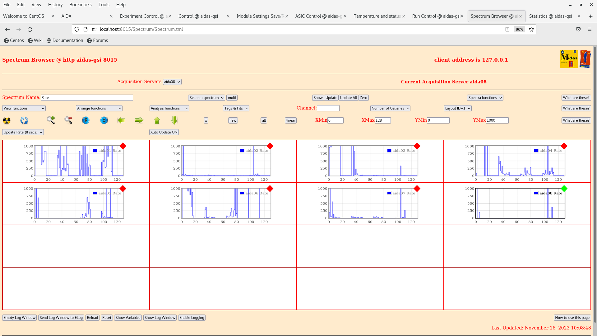
Rates and histograms are observed with bPlast HV connected but not powered. The LIMO cables to the booster cards of bPlast are connected and the TAMEX crate is powered.

The following details the various tests of bPlast configurations and AIDA response:

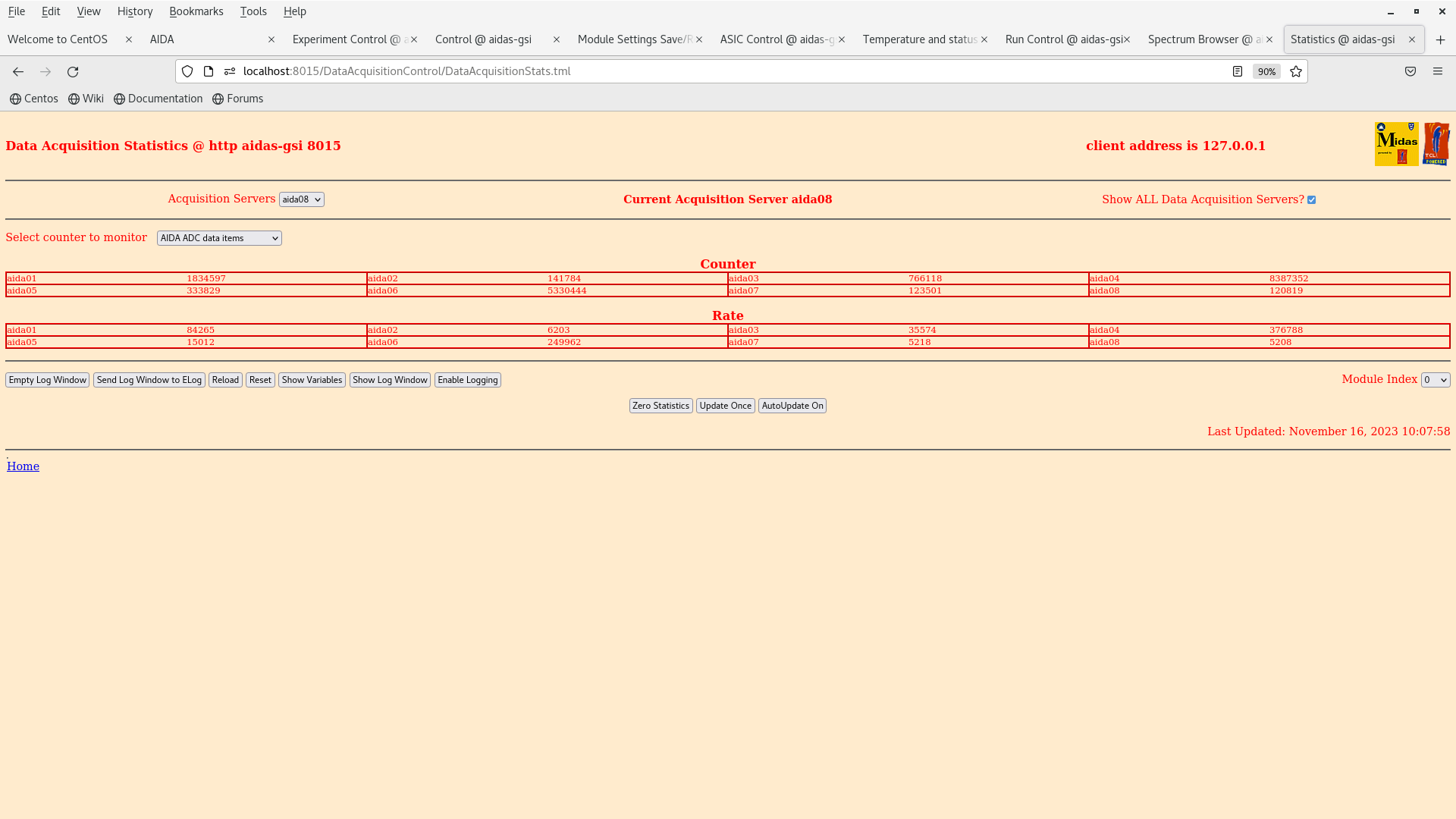
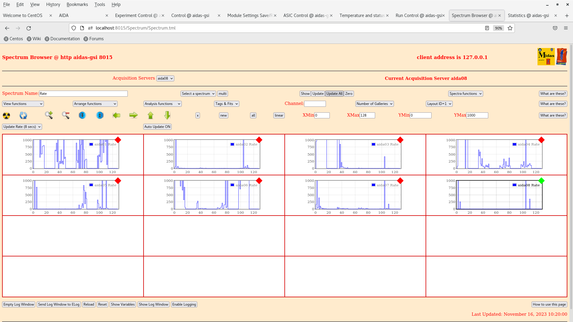
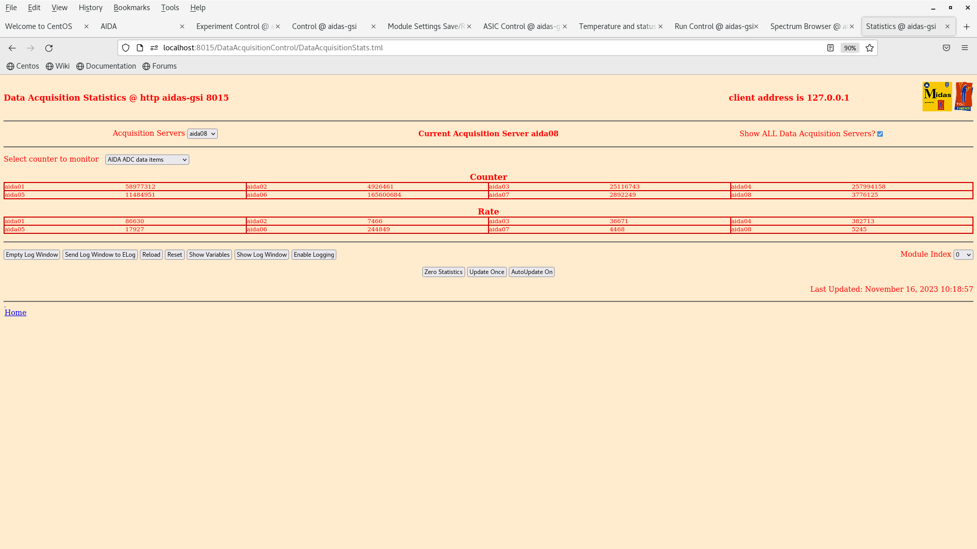
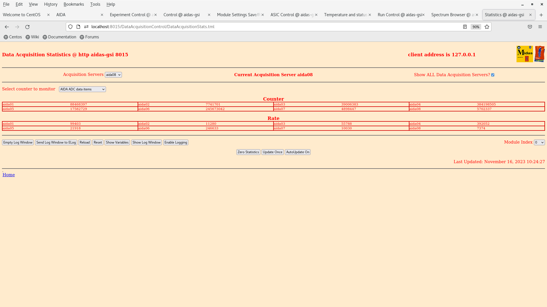
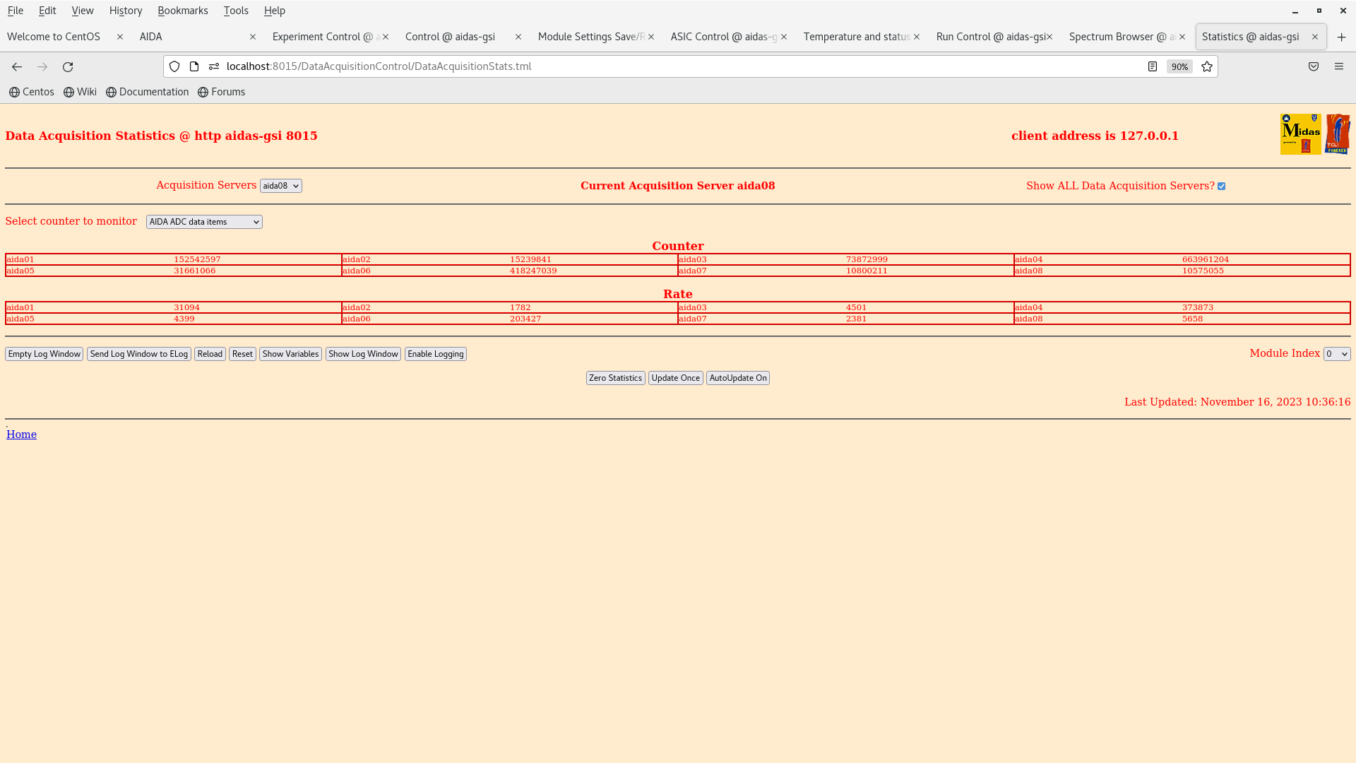
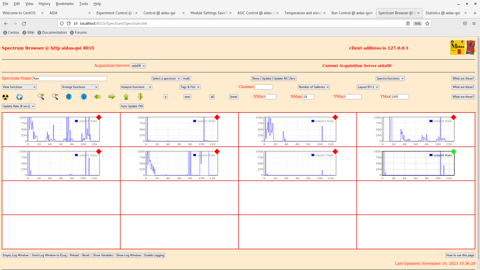
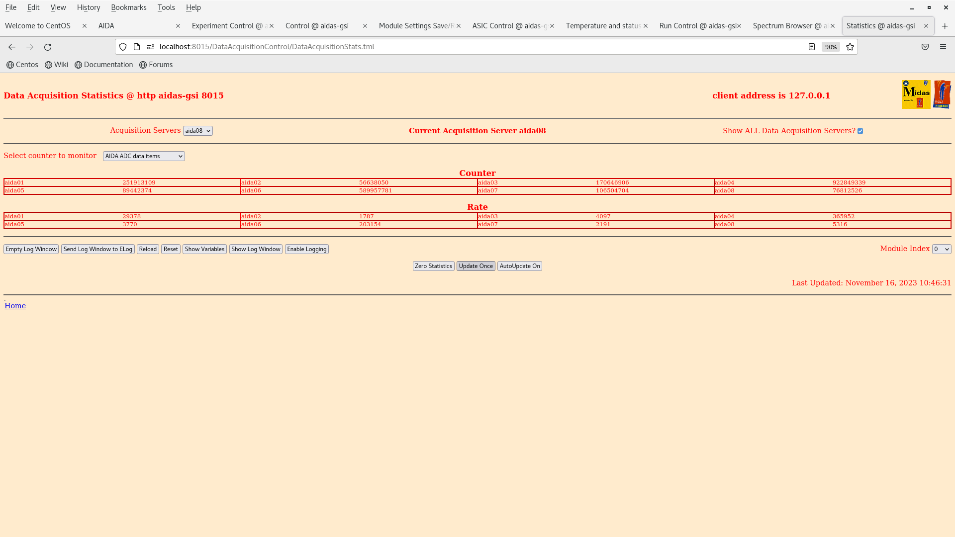
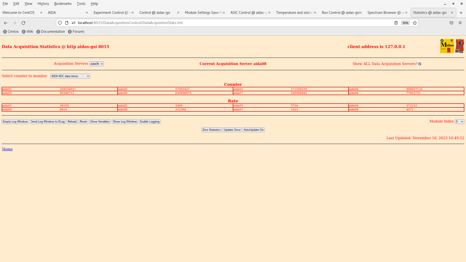
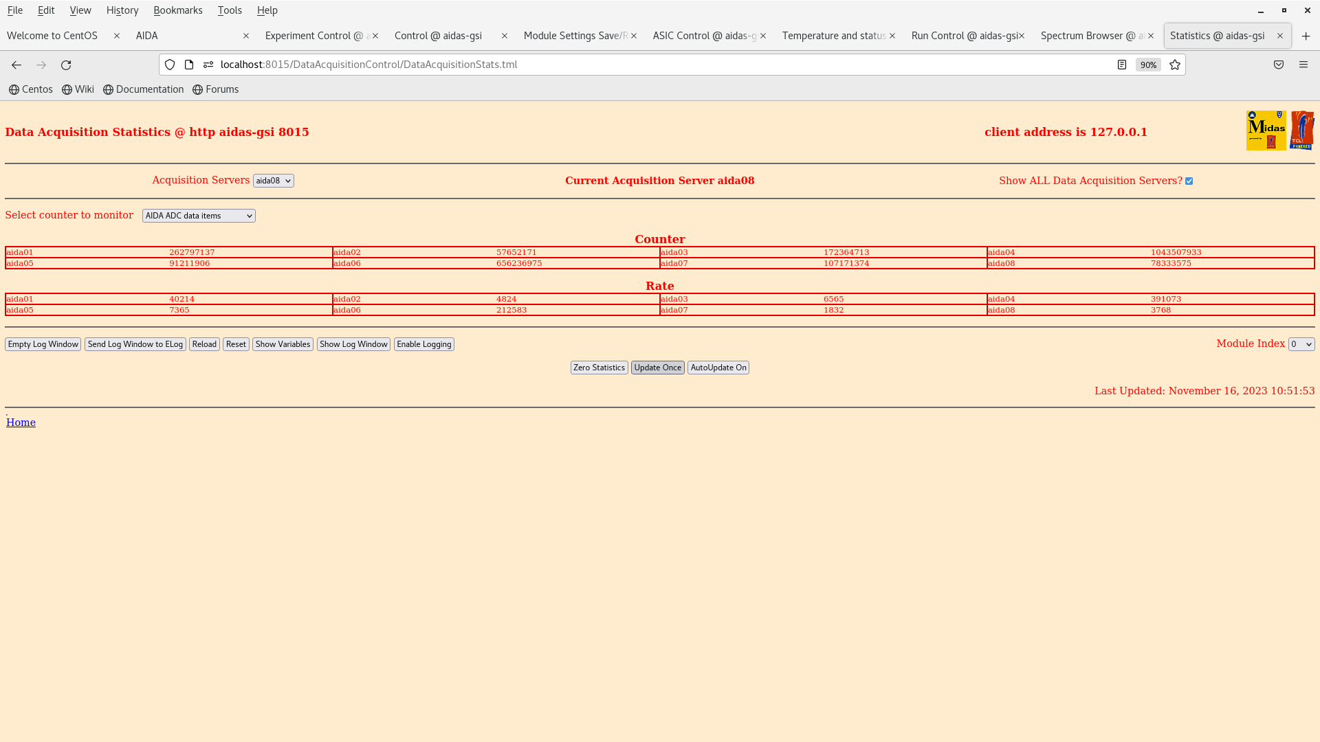
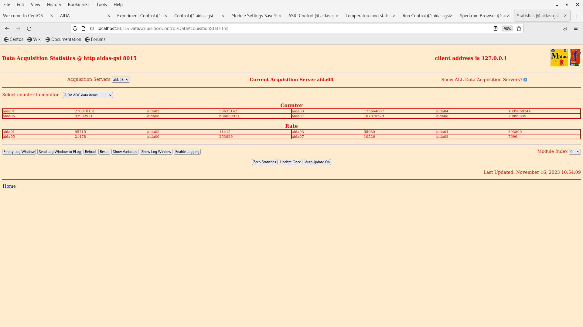
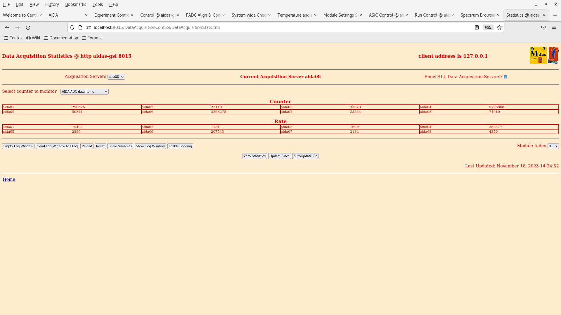
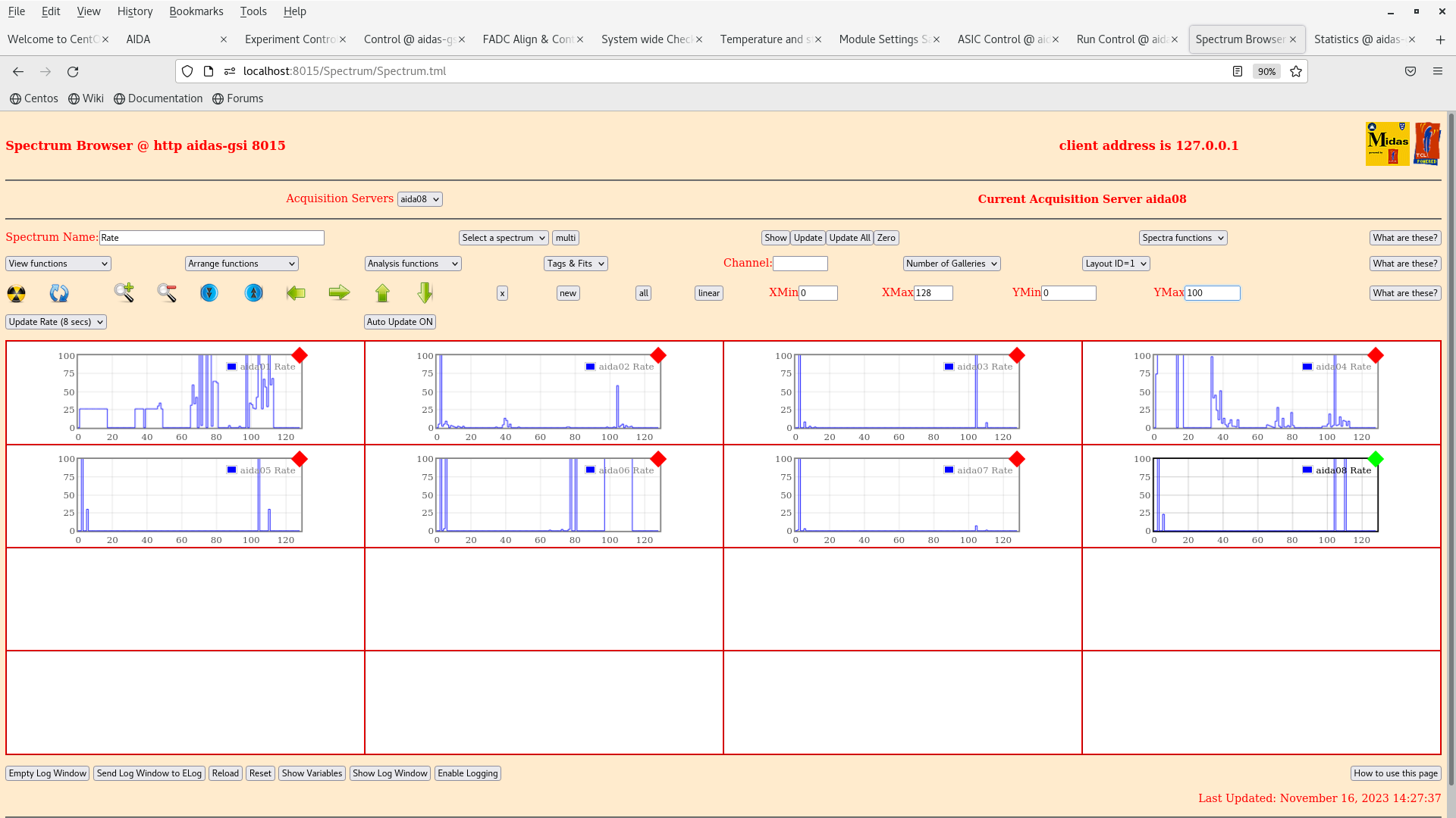
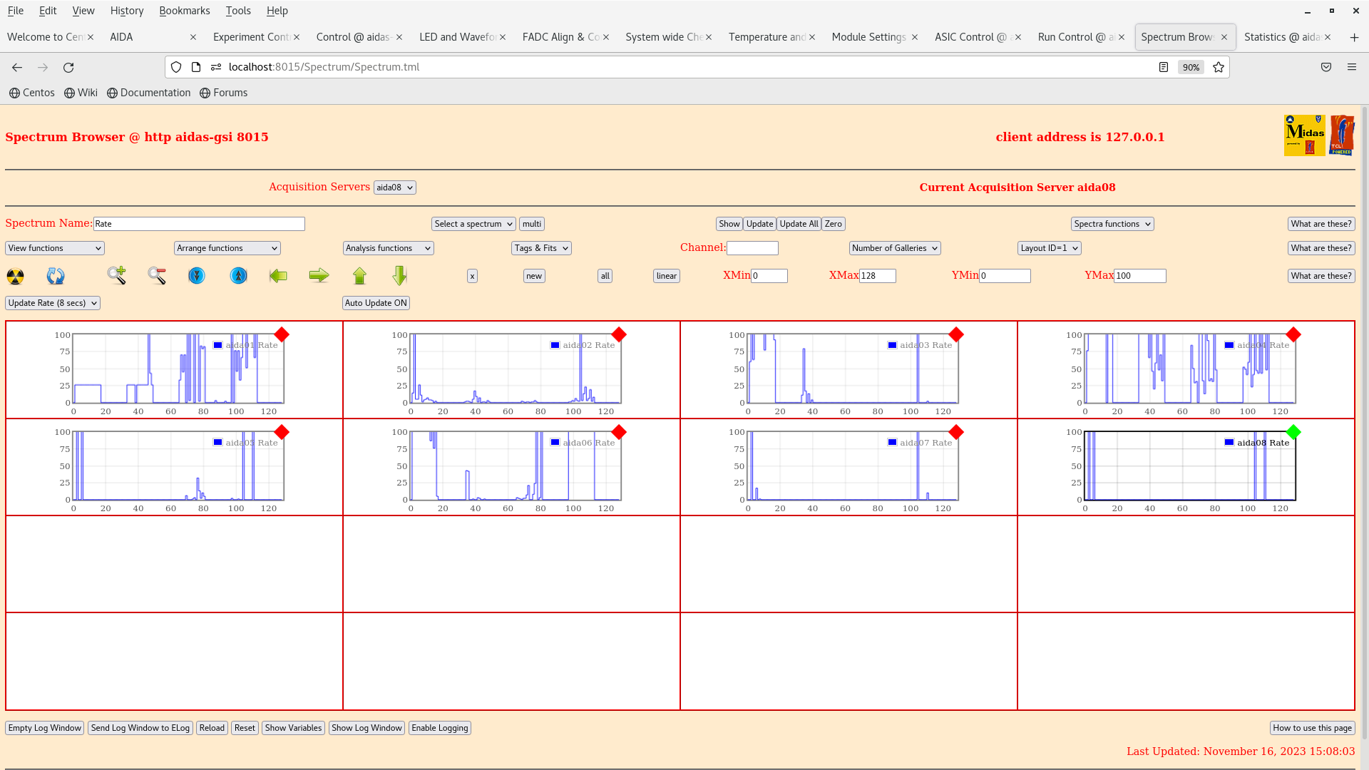
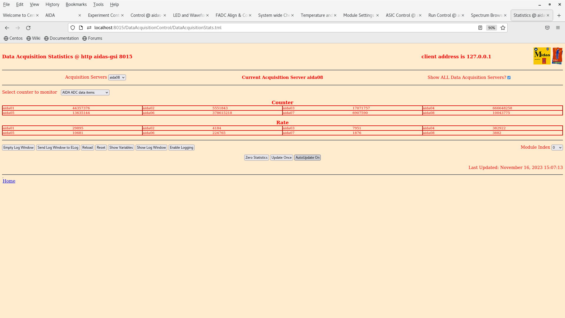
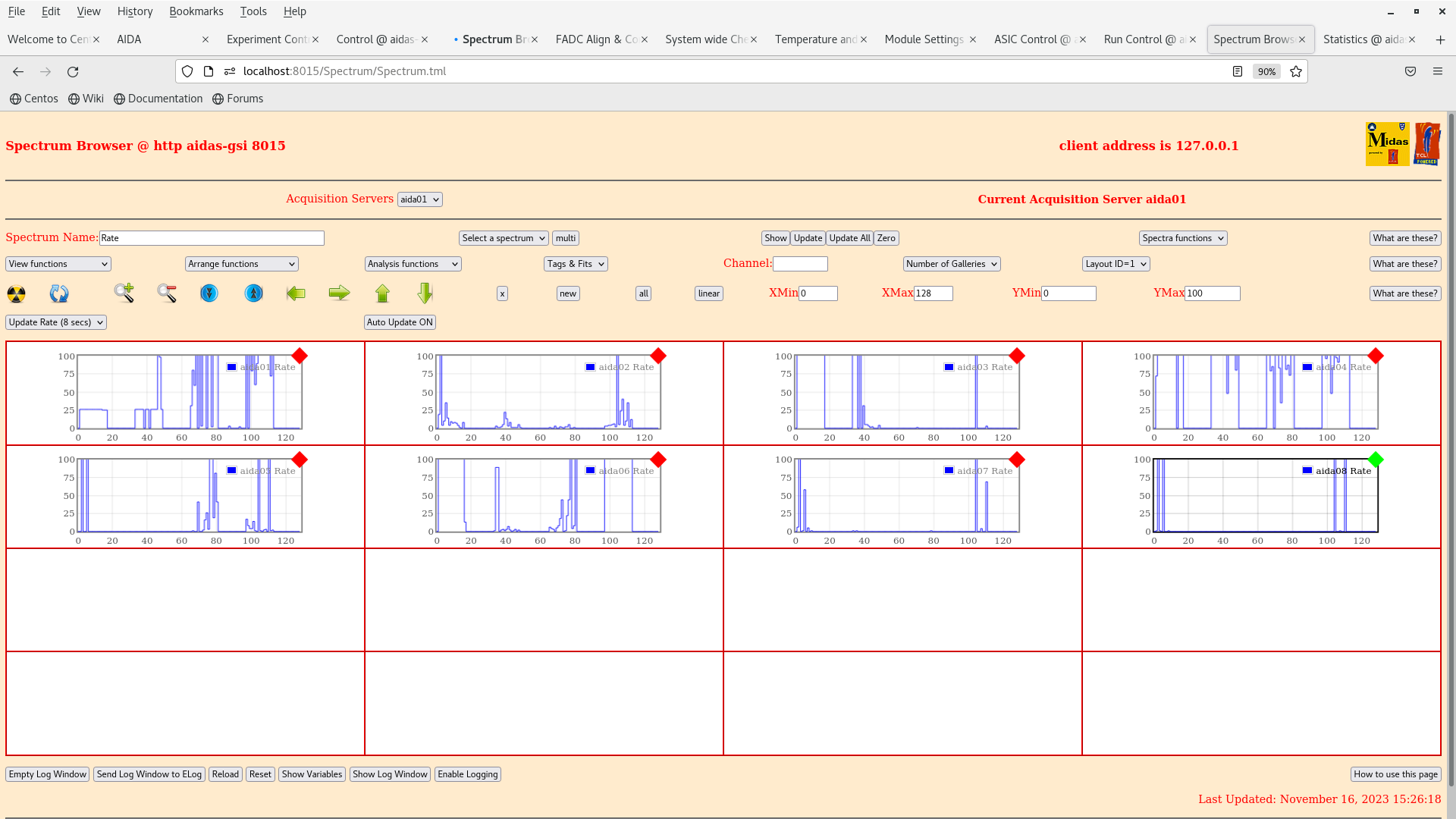
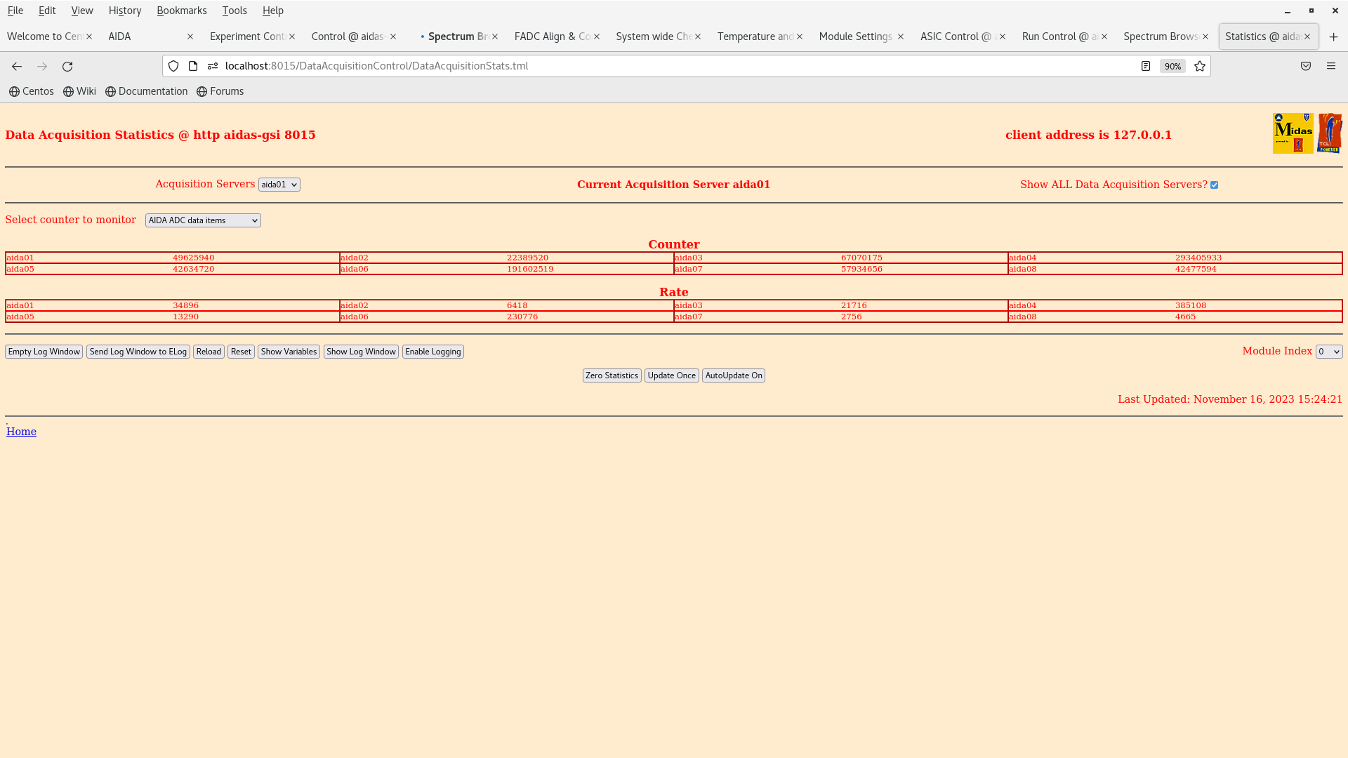
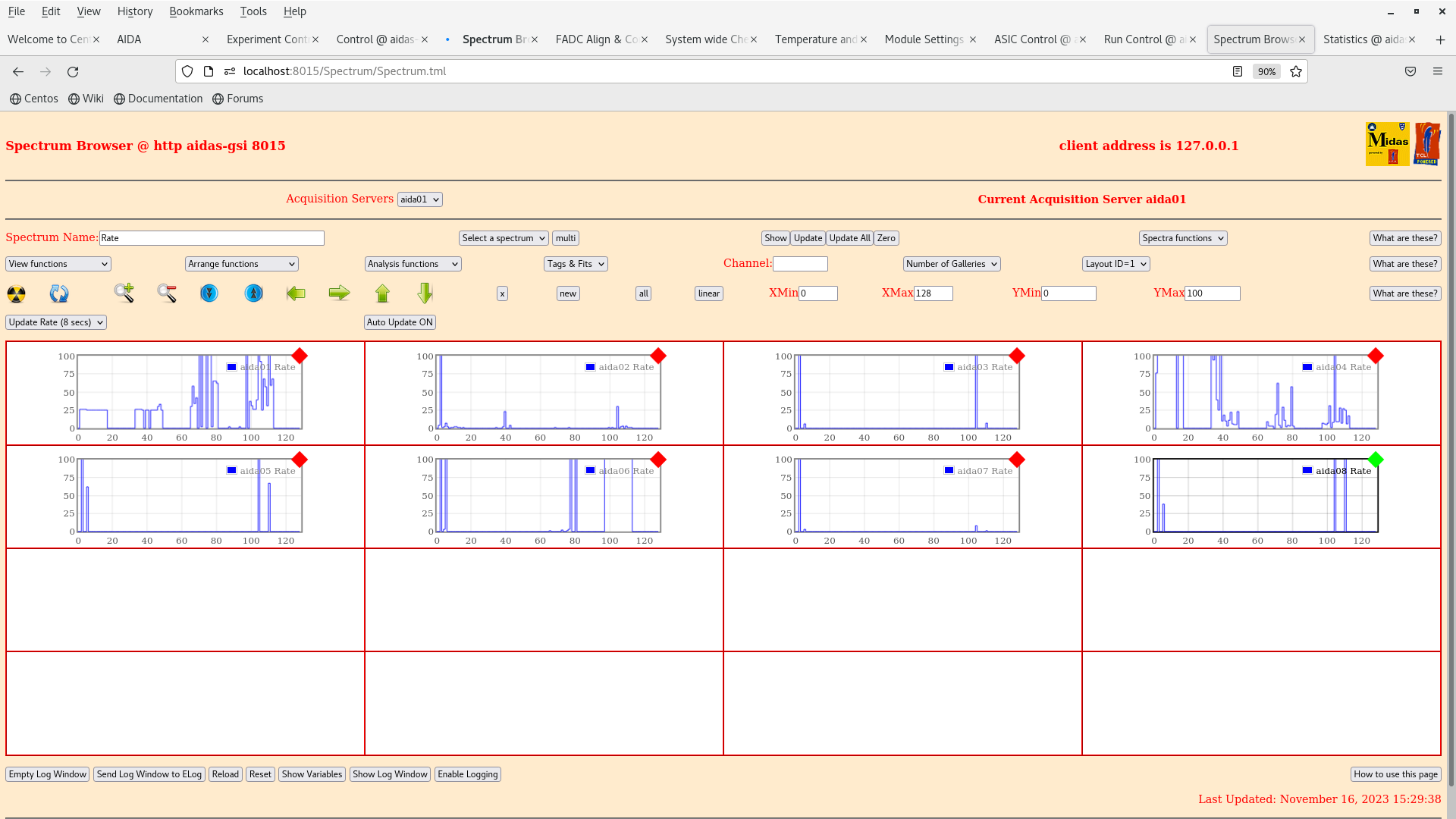
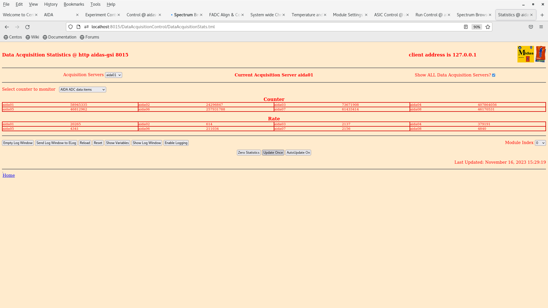
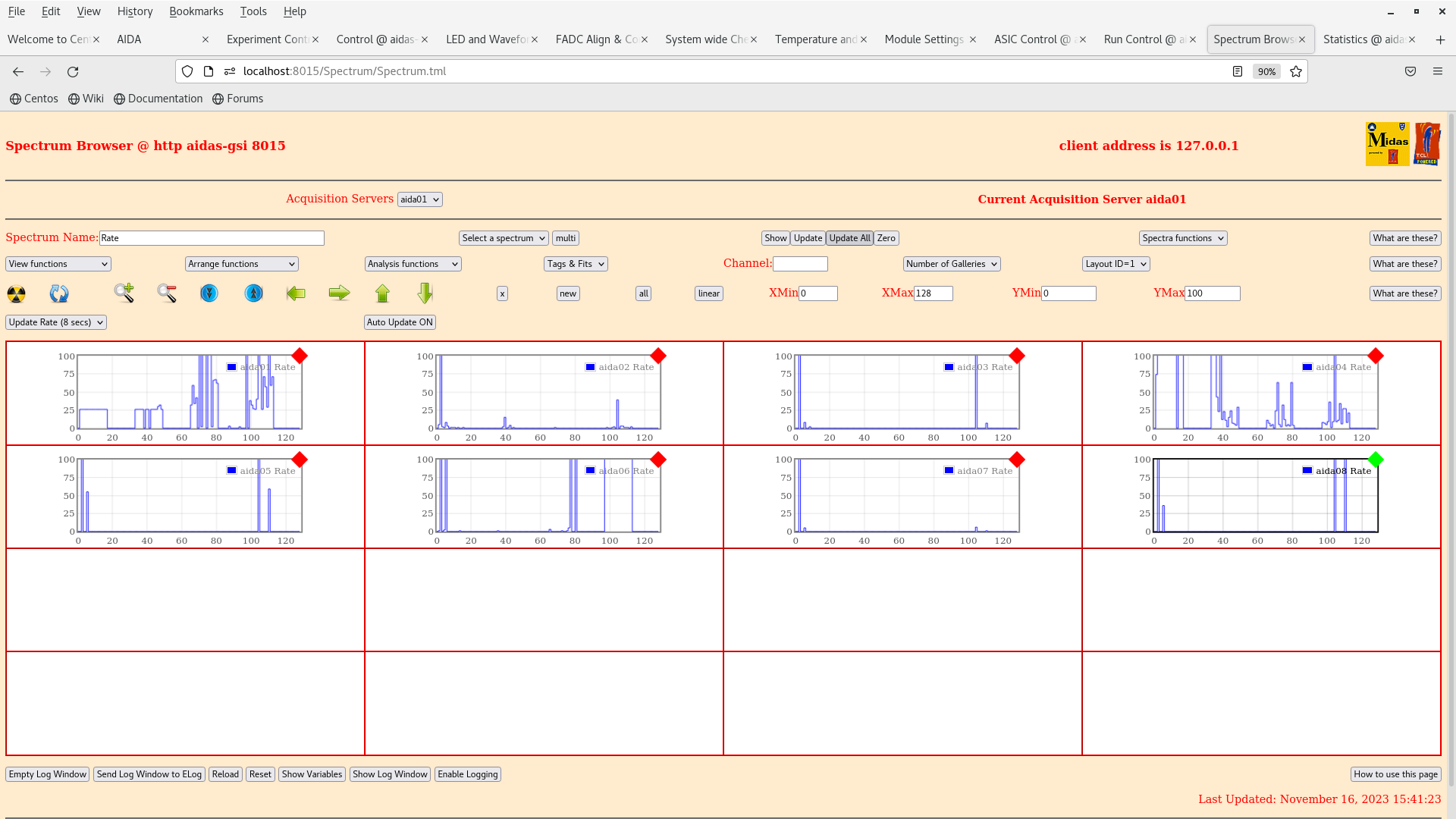
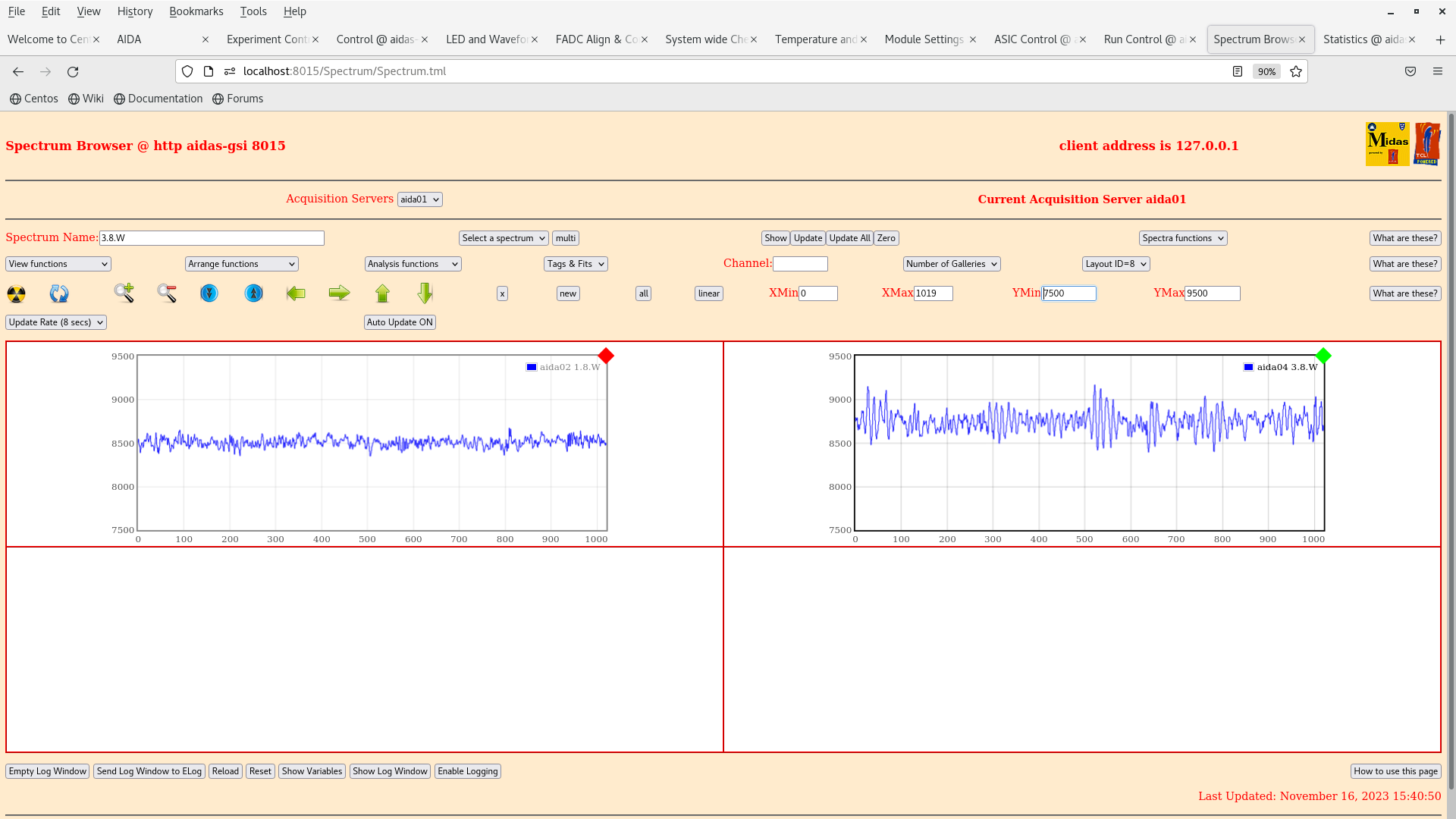
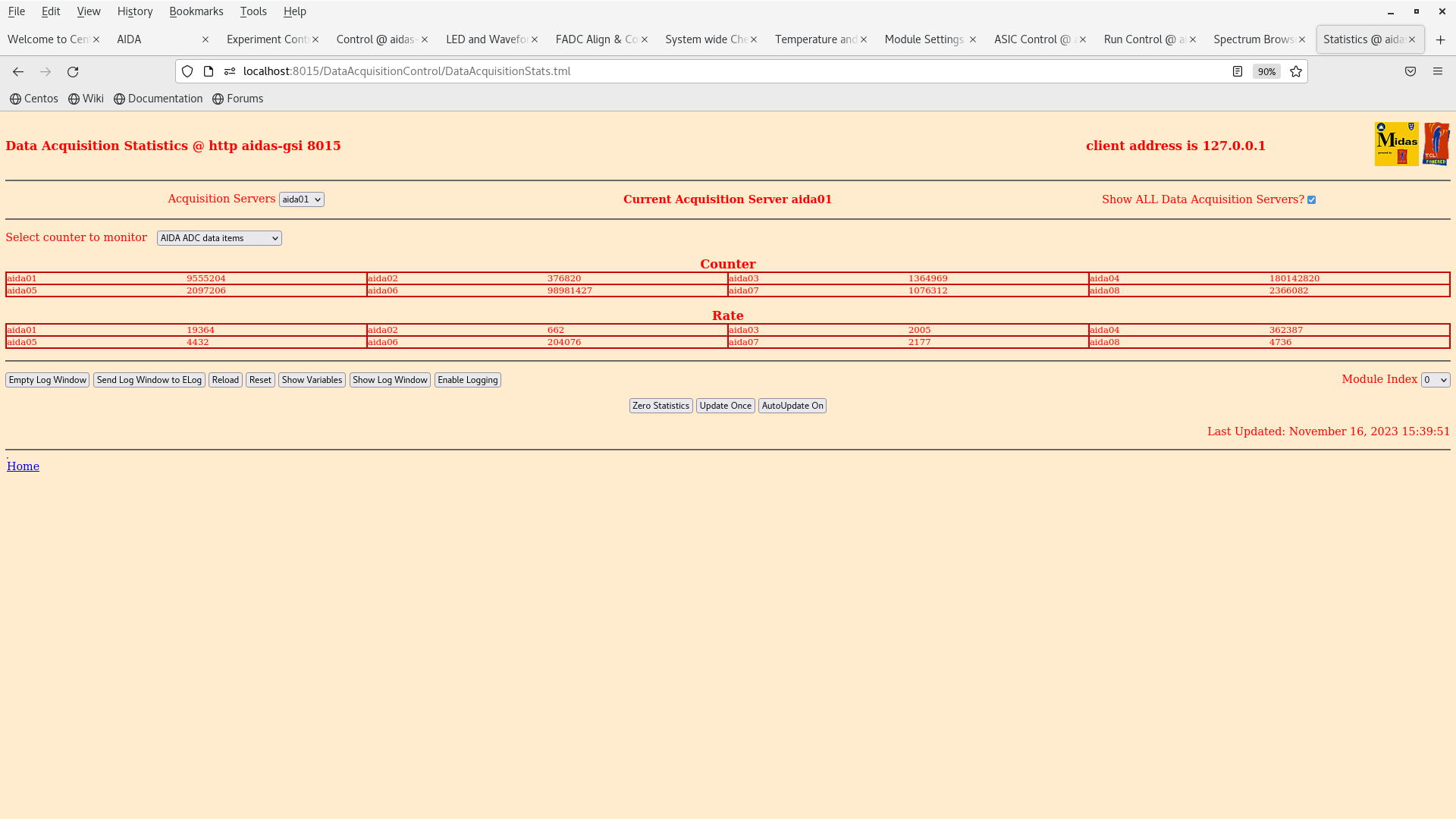
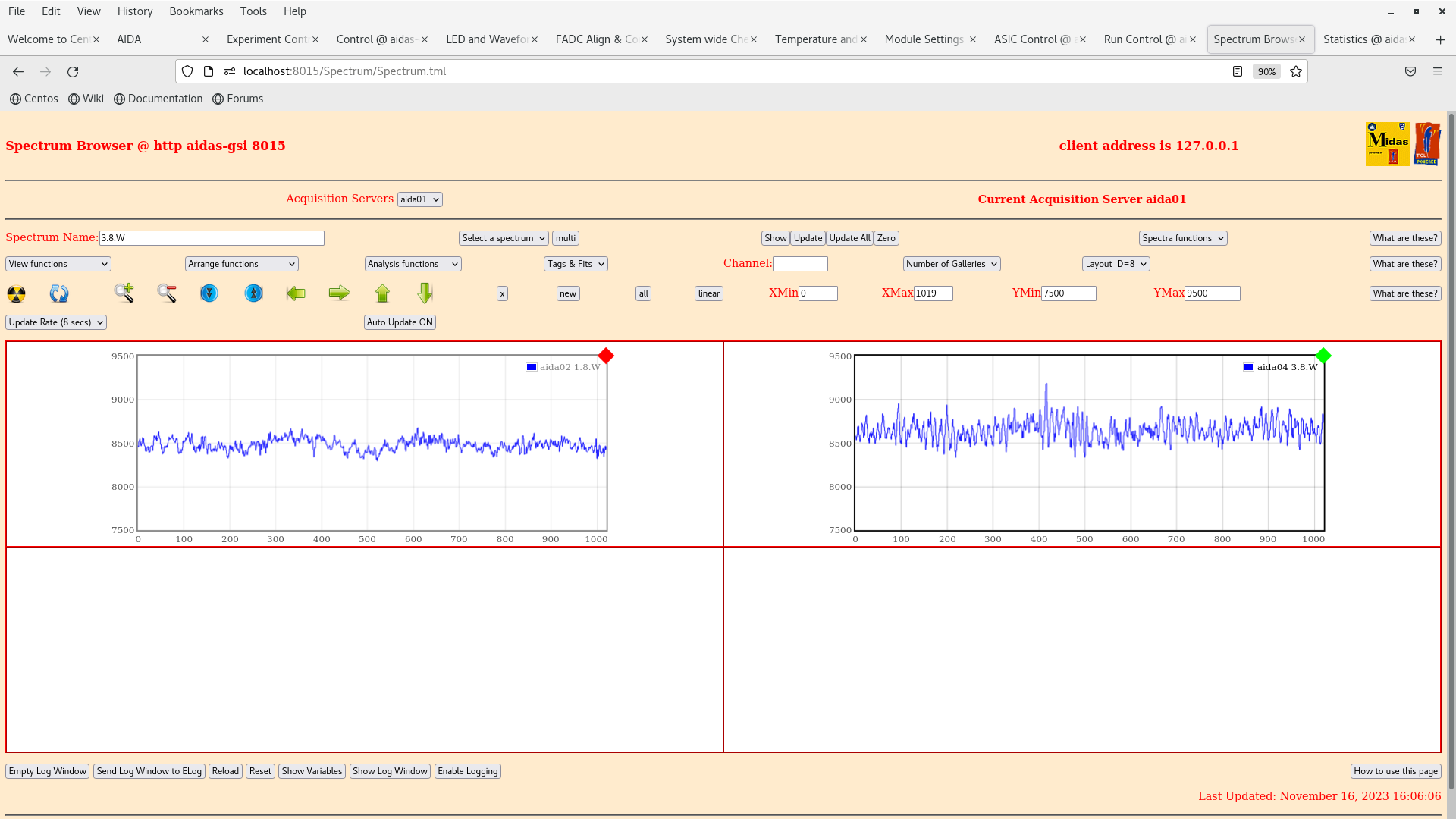
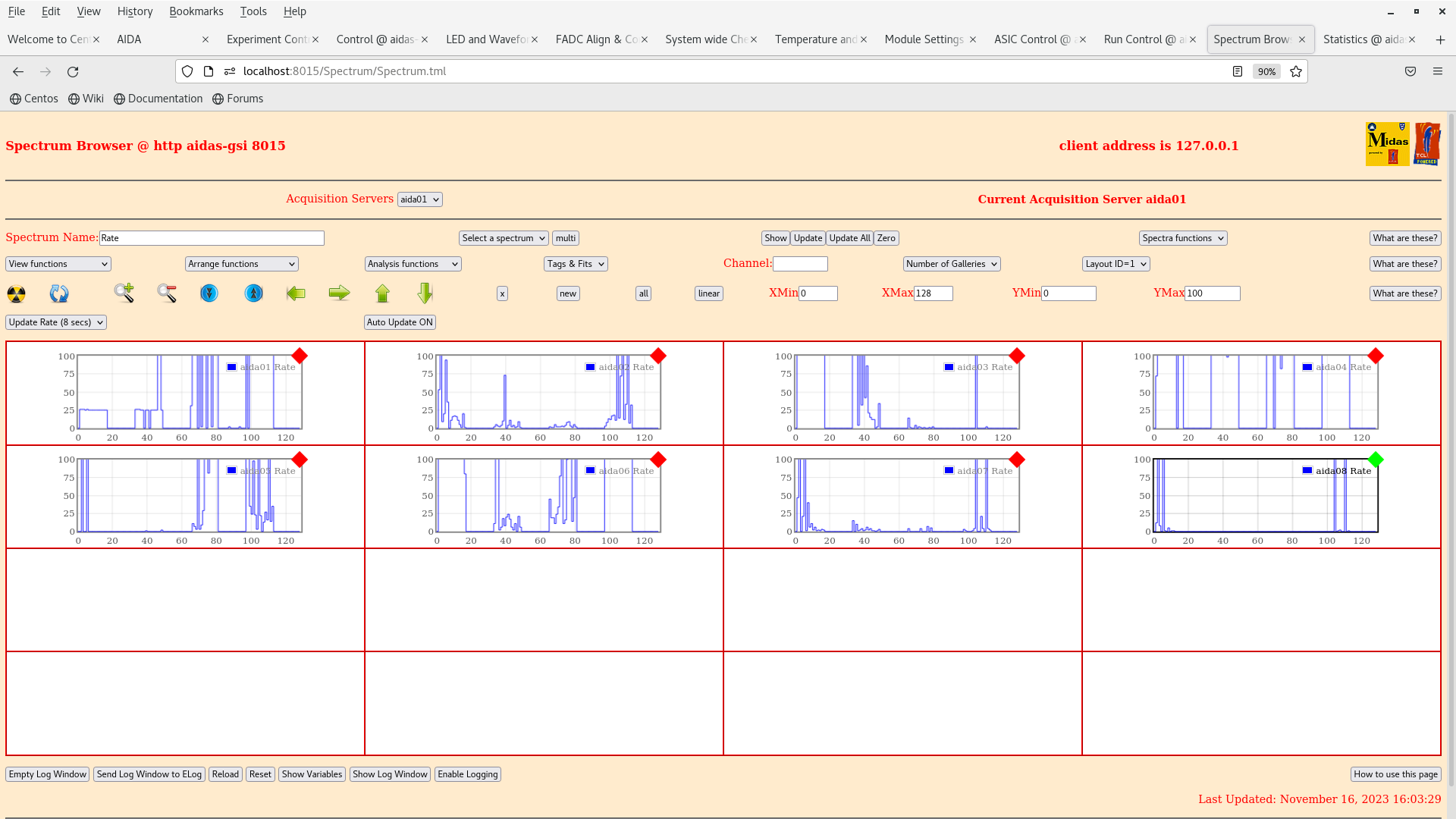
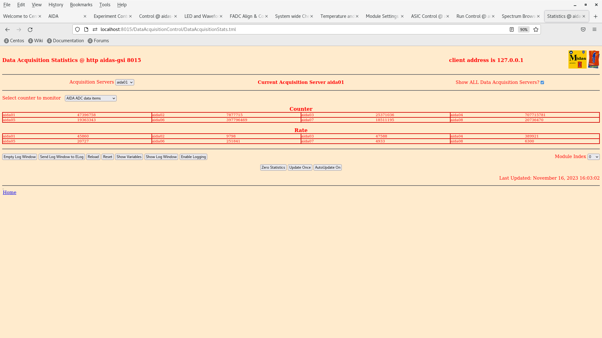
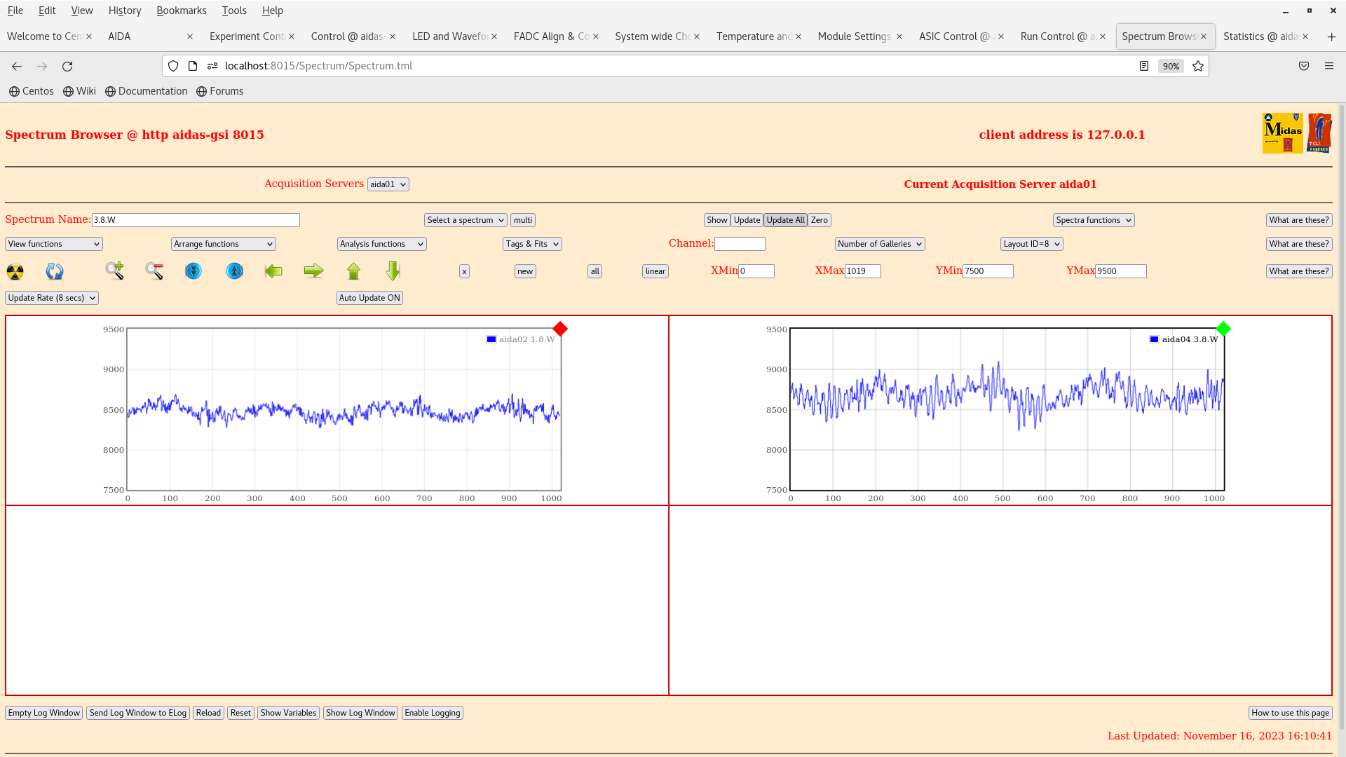
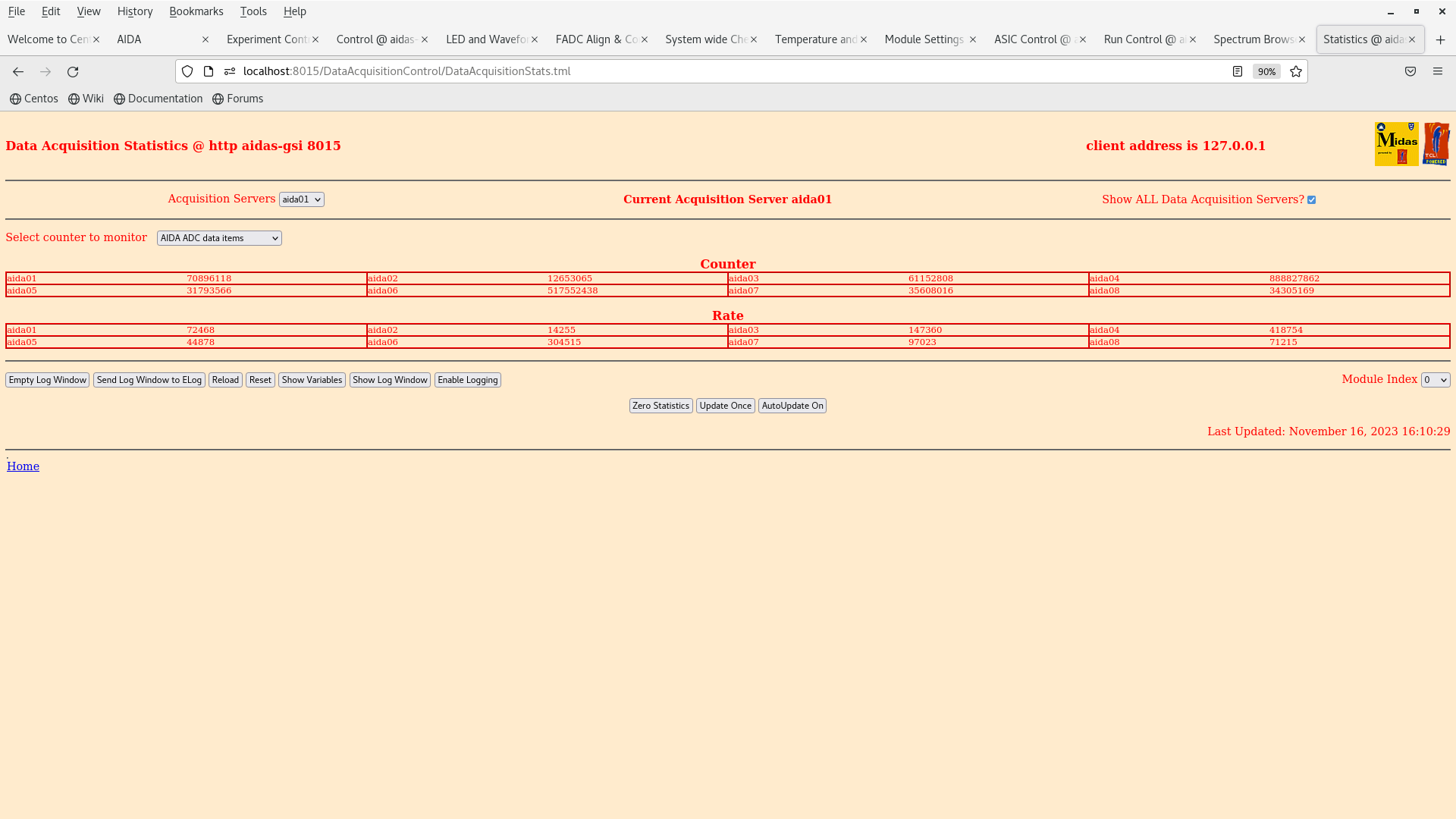
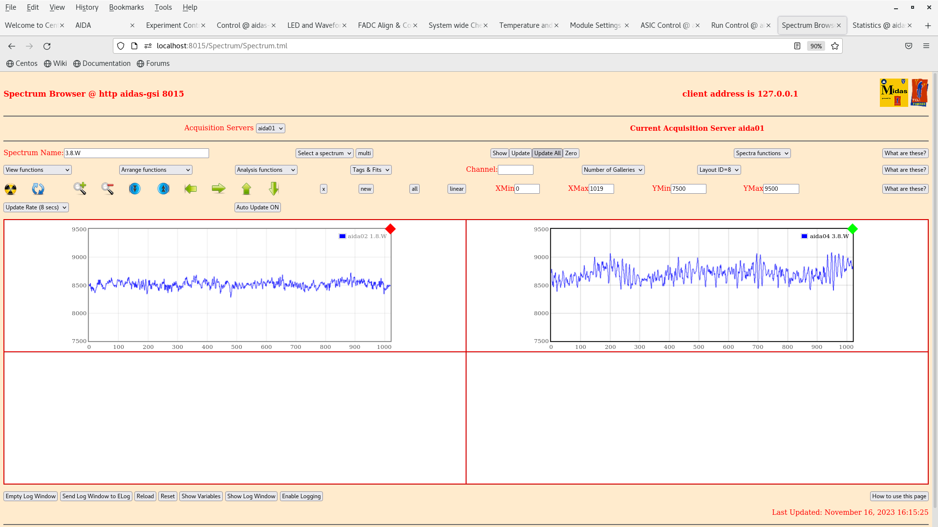
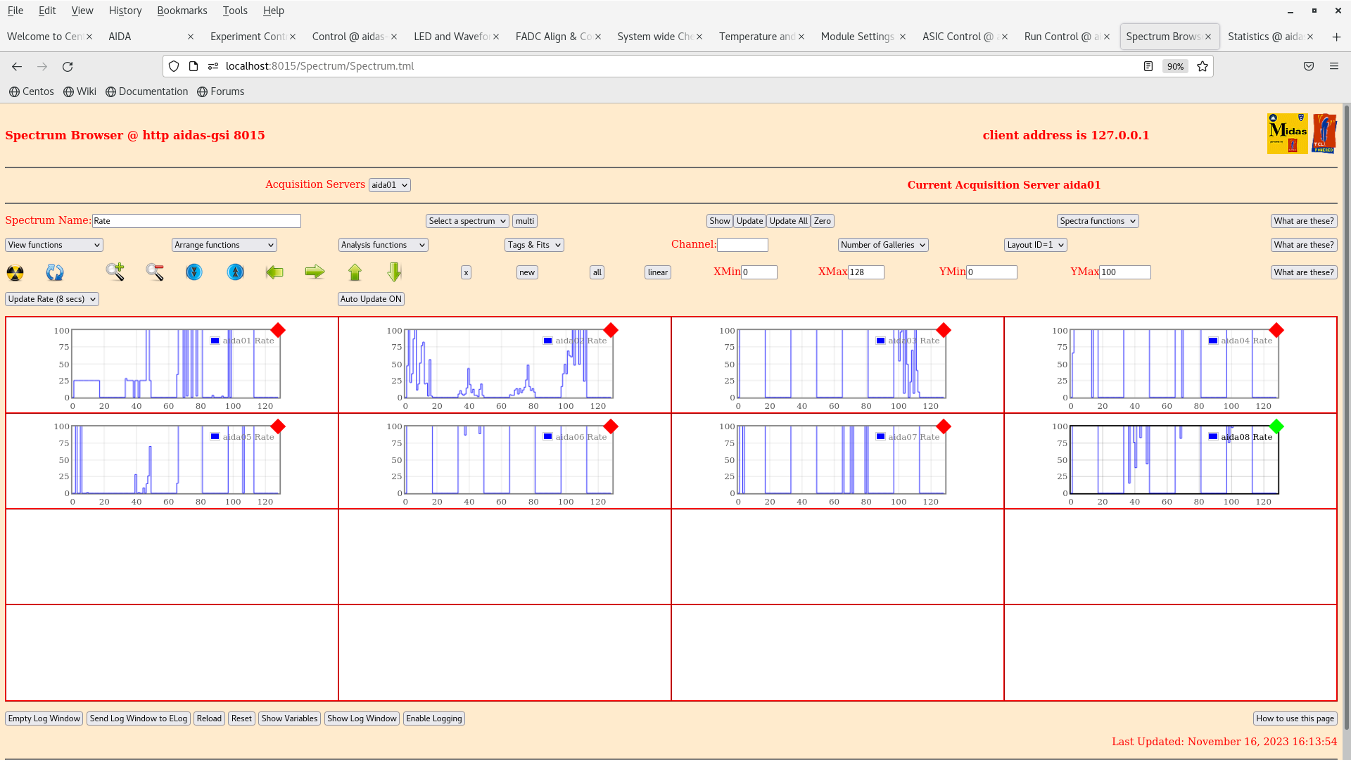
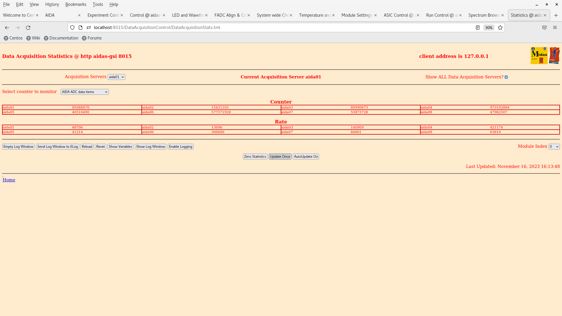
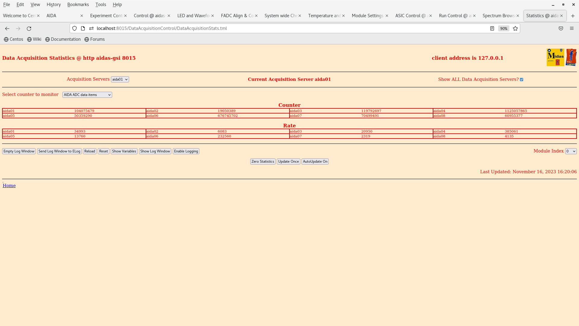
1. The rates and status are the same as yesterday evening (15/11/2023) where we had the same configuration (bPlast connected to HV but not powered). (Attachment 1-3)

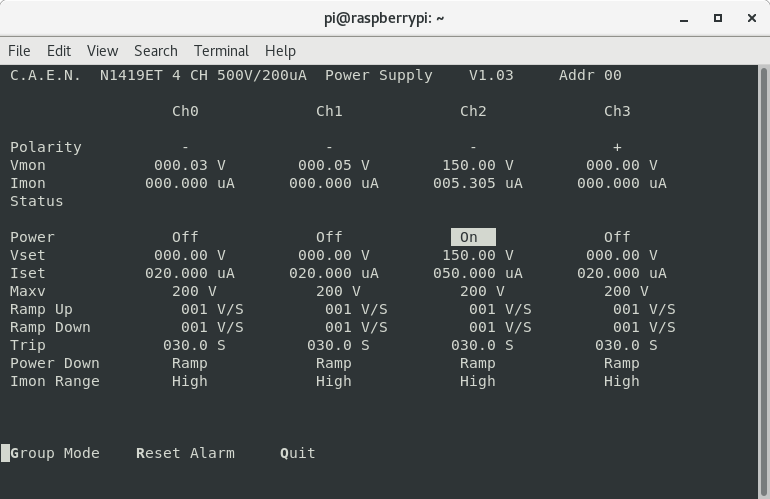
2. The rates and status are the same as in 1. when trying a different power supply but it is not turned on (Attachment 4-5). The R&S HMP4040 HV supply is a linearly regulated supply while the new supply is suspected to be switching regulated (?).

3. The rates and status are the same as in 1.,2. if the HV supply is connected. In fact they seem to increase when disconnecting the HV supply. (Attachment 6).

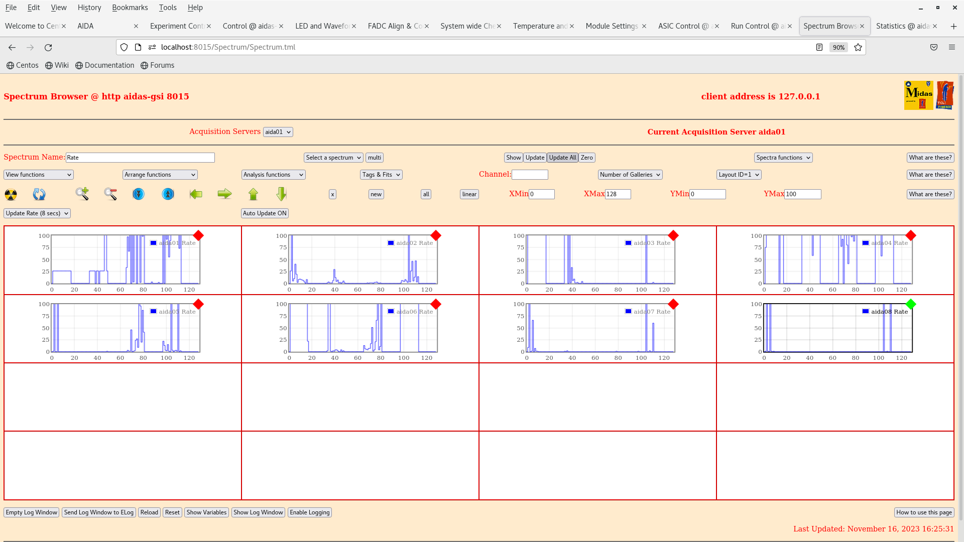
4. The rates and status are brought back to acceptable levels when disconnecting all the LIMOs of the bPlast booster board to TAMEX. (Attachment 7-8).

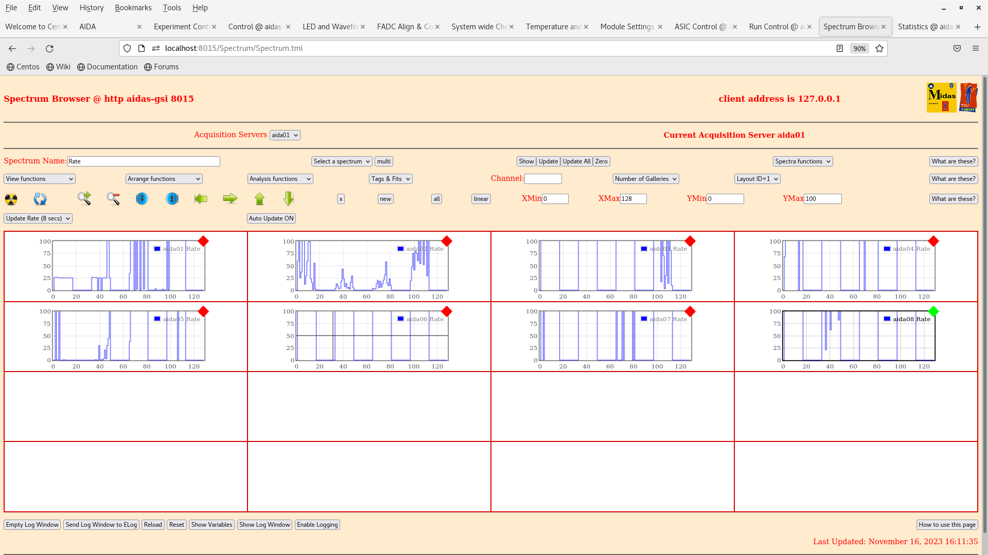
5. The rates and status are fairly worse when connecting a single LIMO (attachment 9) and when connecting the Mesytec module that powers the booster board (attachment 10).

6. The rates and status increase a little favourably when connecting a single LIMO to an odd numbered channel. (Attachment 11).

7. The rates and status are dramatically worse when connecting two LIMOs and a Mesytec module to the bPlast booster card. (Attachment 12).


The next tests will be dismounting the snout and trying to shield the bPlast ribbon cables with copper tape.

Tests resumed after lunch 14:00:00:

- The bPlast ribbon cables running to the booster boards were insulated with copper tape and kapton tape, and for the moment grounded freely with a tinned copper braid. A multimeter check of the ribbon cable showed that it is isolated from the snout as desired.

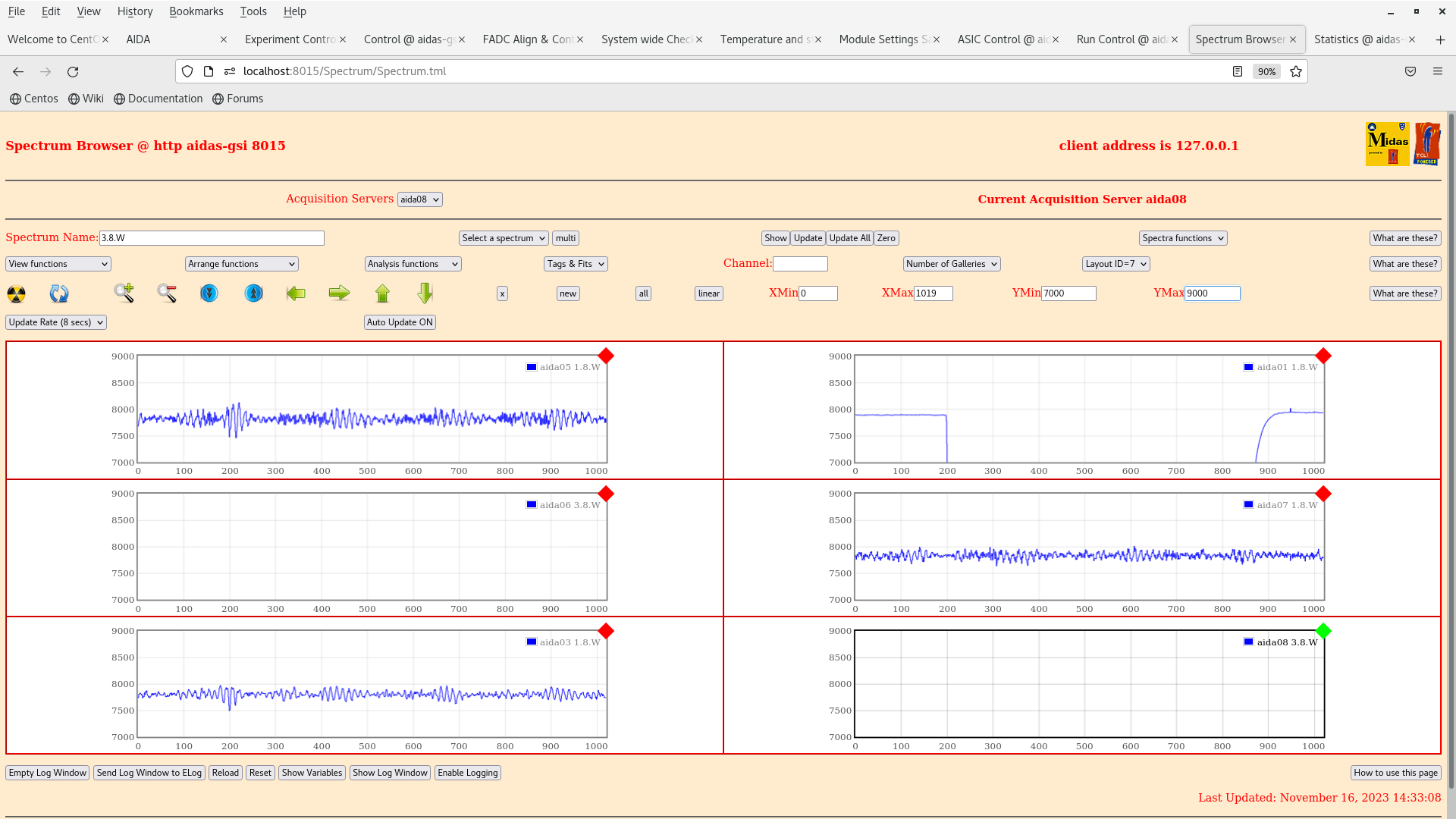
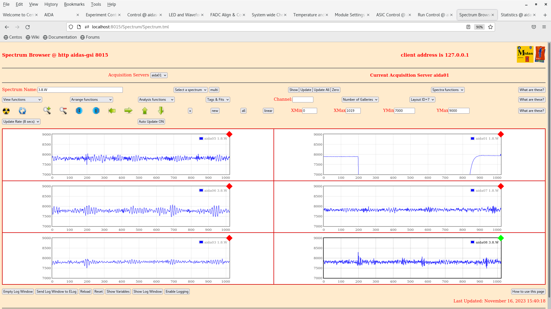
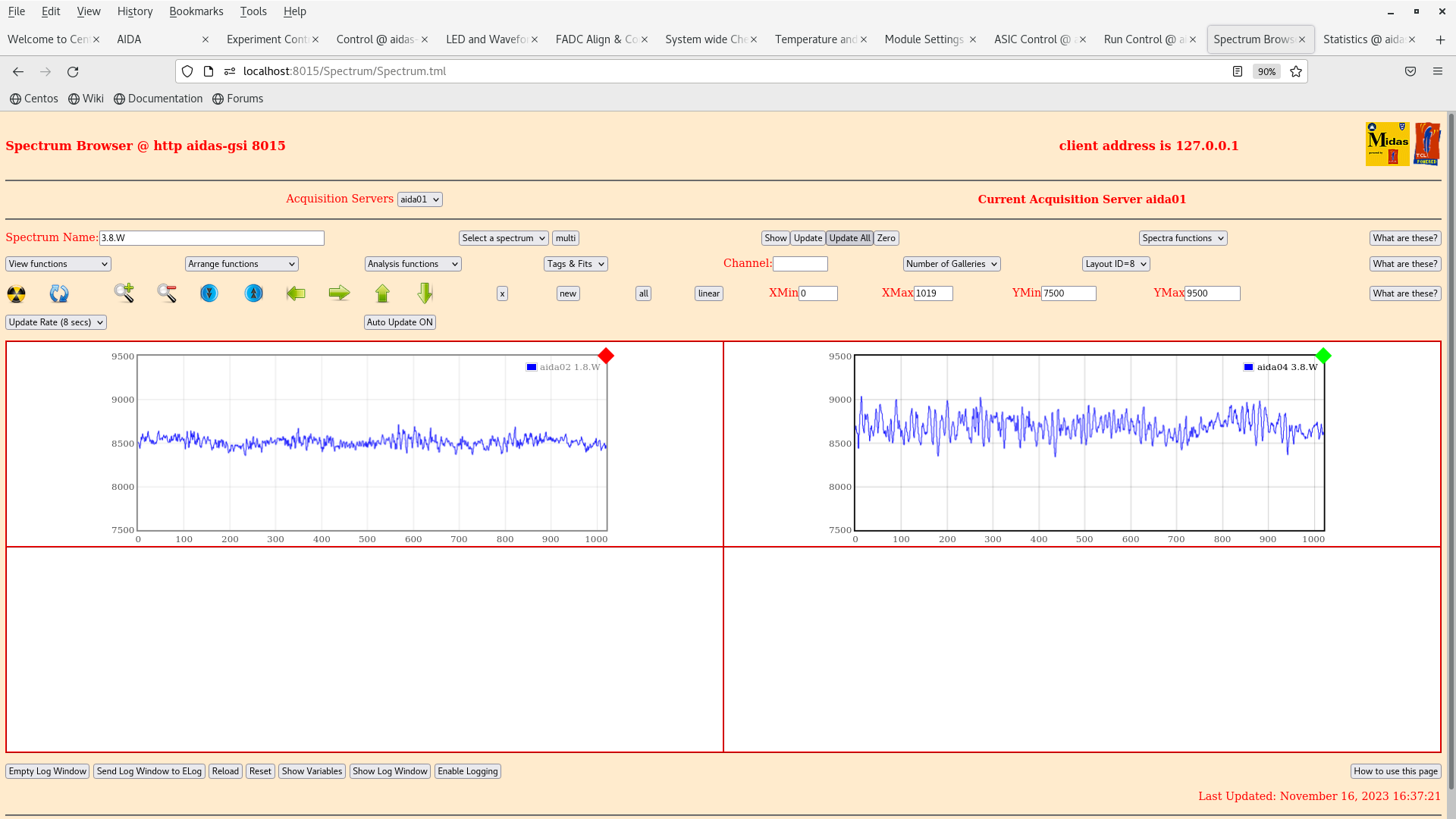
- Remounting the snout we found the following result on the AIDA rates and hit patterns (Attachment 15 & 16). The rates and hit patterns appear to be the same as it was before bPlast was mounted in the snout. The connector cable of AIDA01 was found to be broken for ASICs 1&2 (3&4 are still connected), and the noise on AIDA04 has increased slightly relative to previous tests.


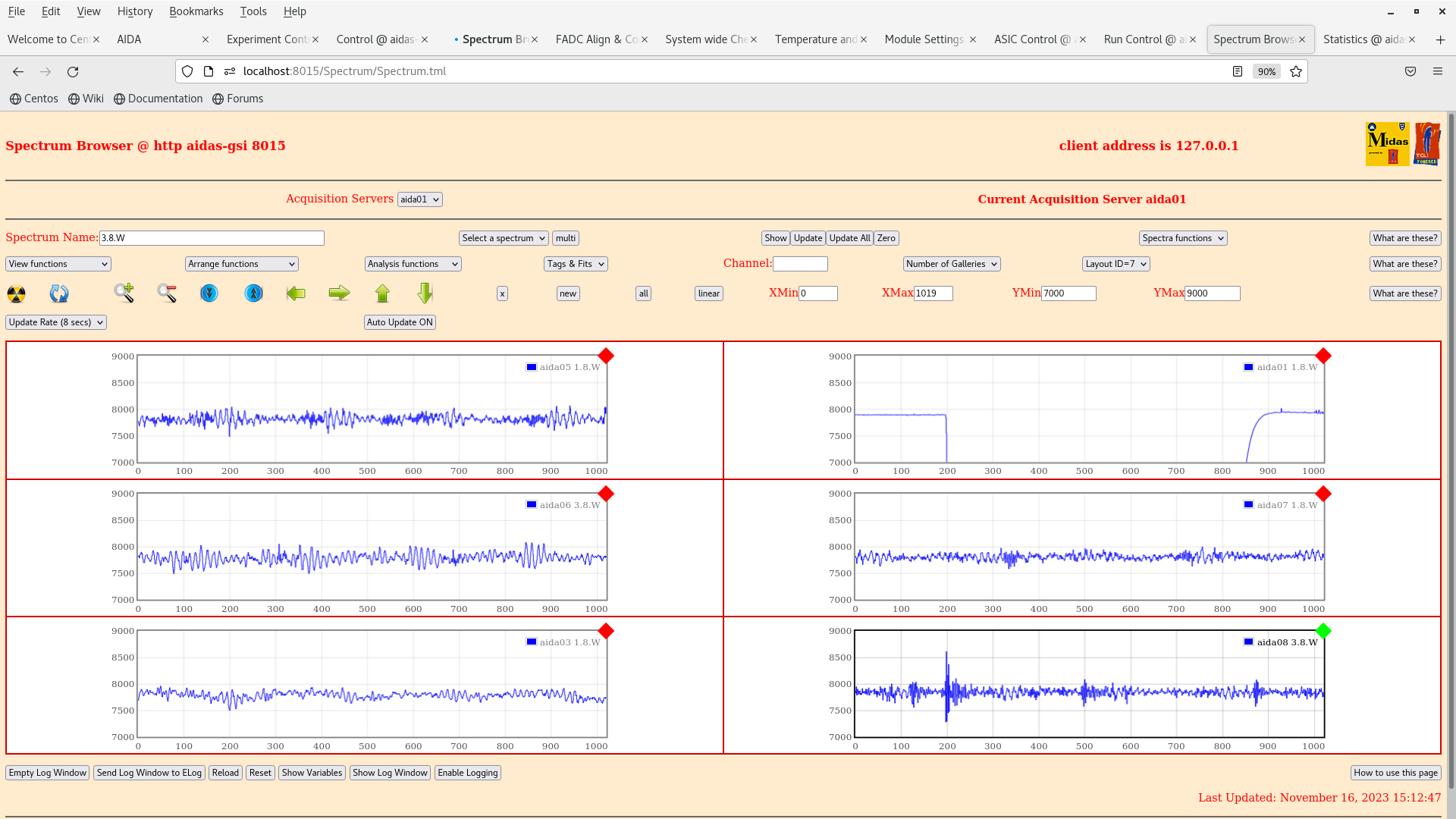
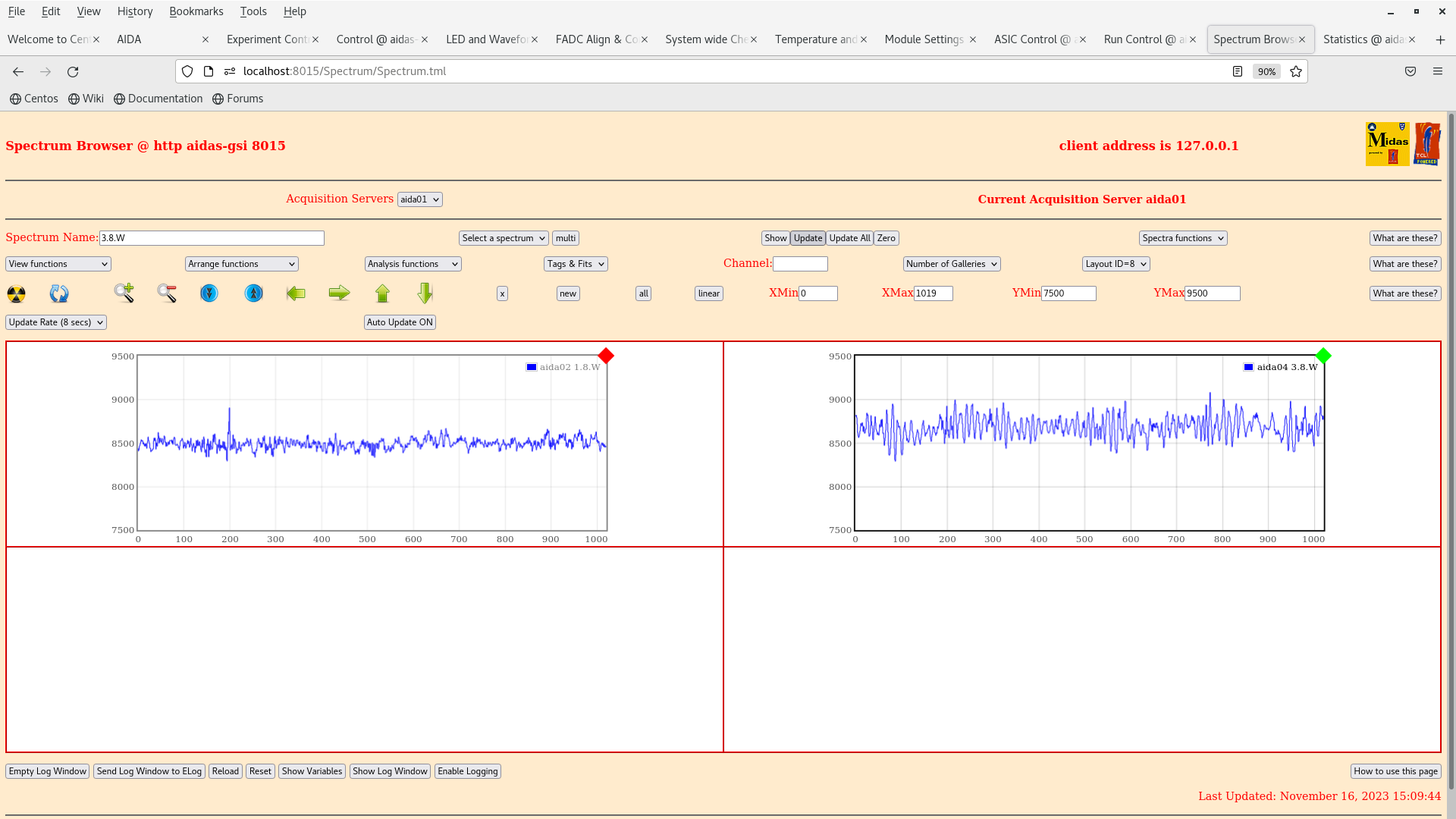
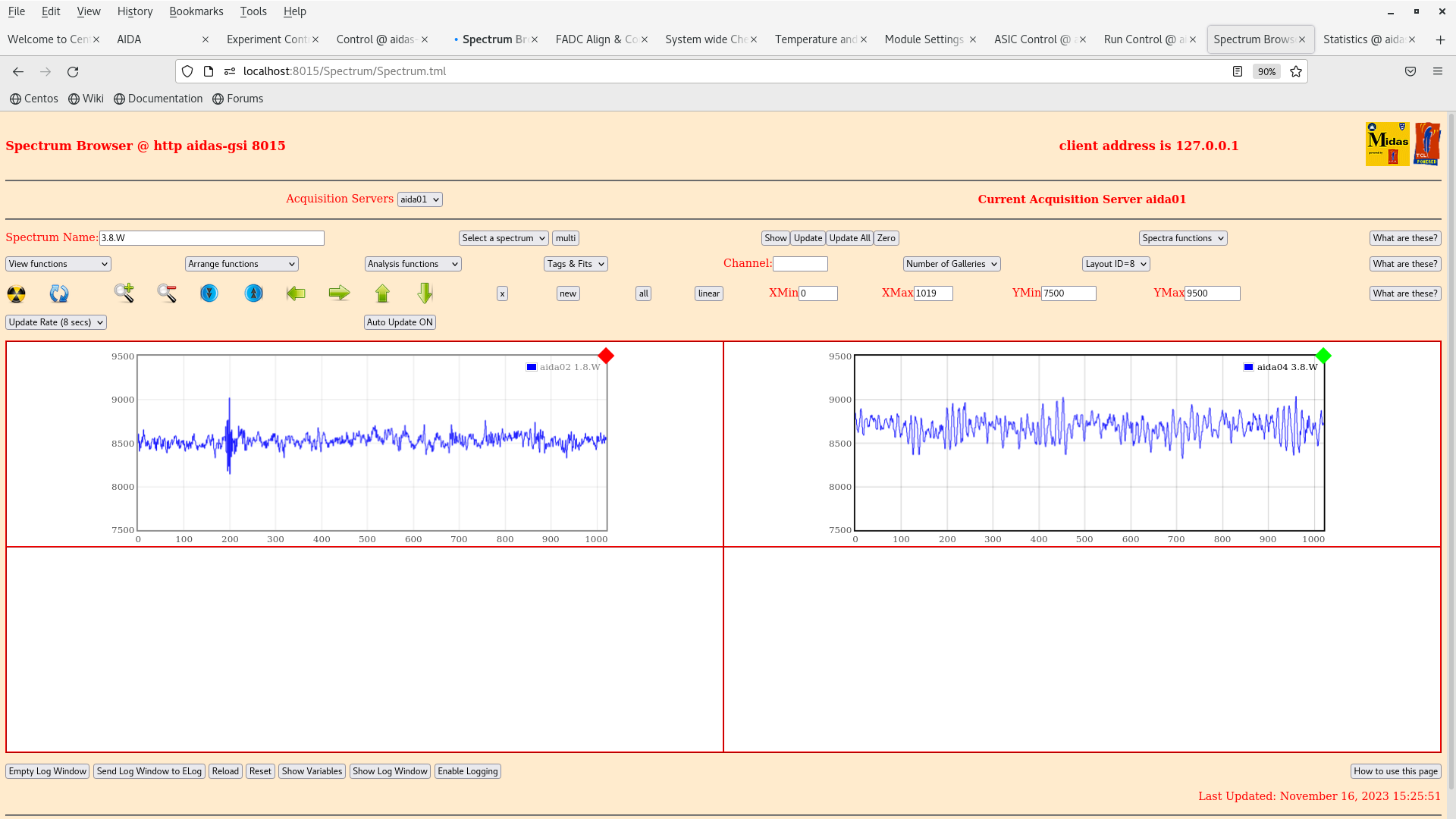
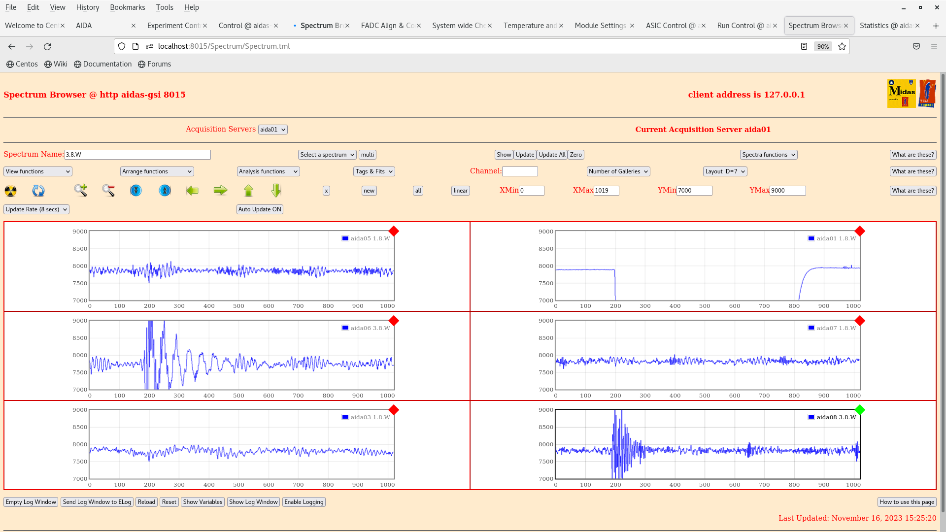
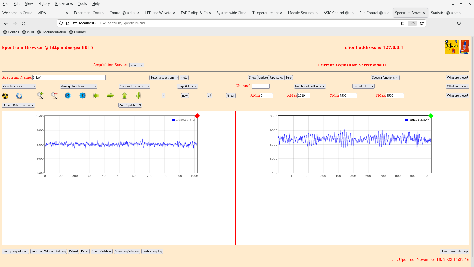
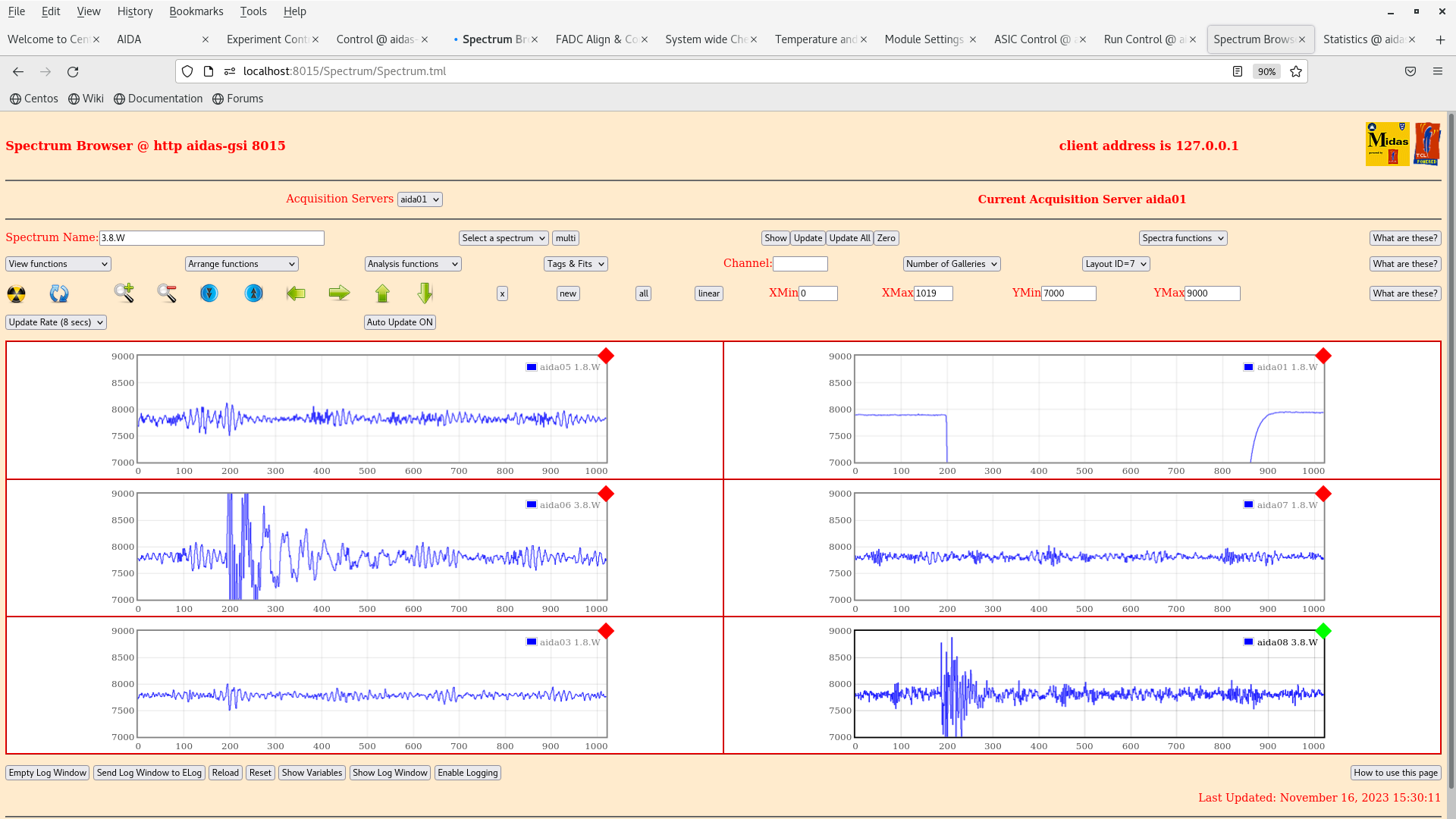
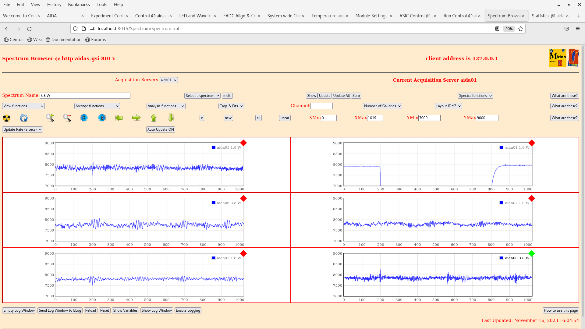
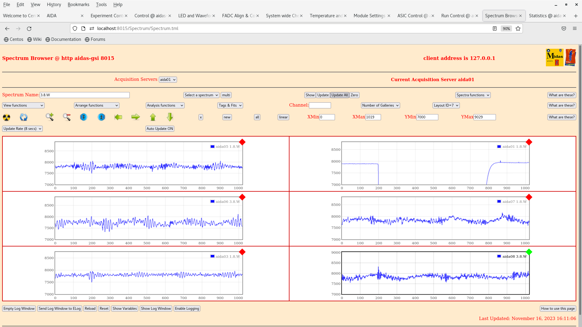
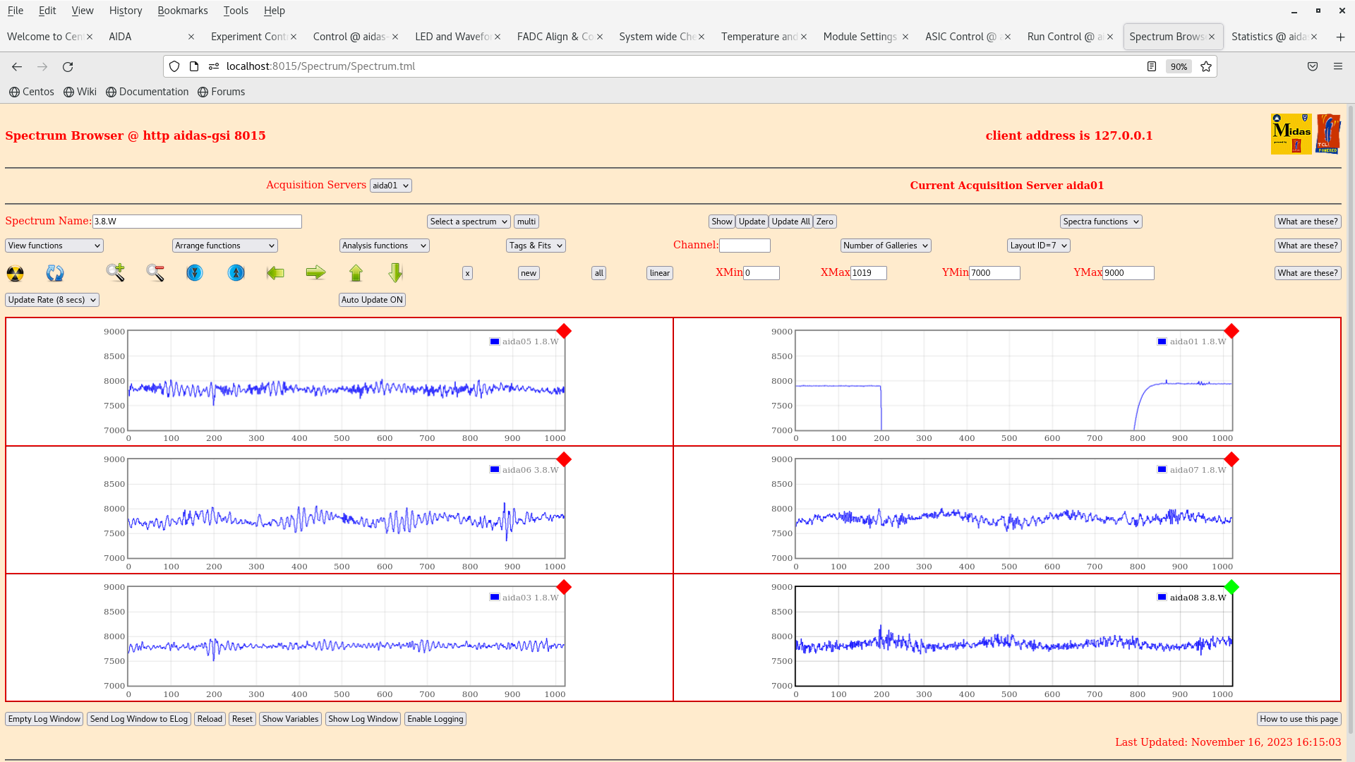
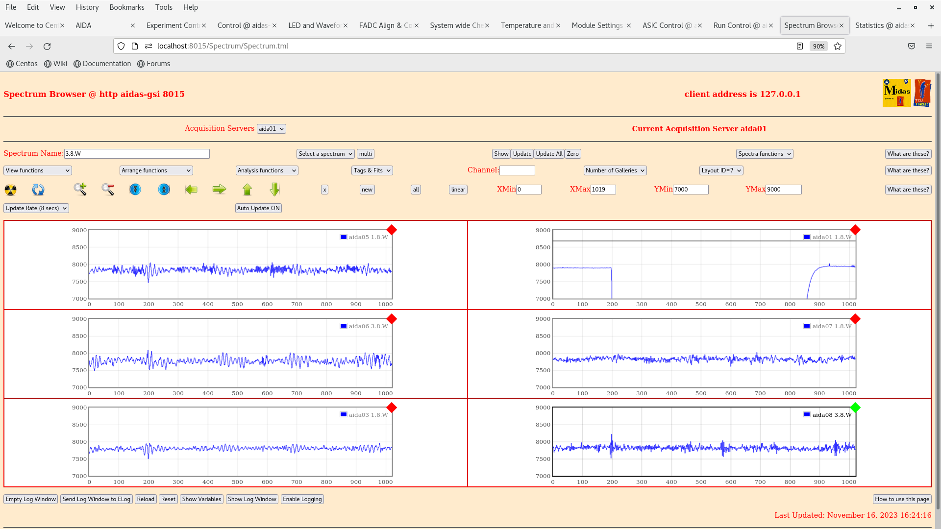
8. The wave forms of the AIDA modules show regular structure. There are some high frequency 'beats' present in some of the AIDA modules (Attachment 13-14). The waveform of AIDA01 has the pulser signal (25 Hz), but has no noise as ASIC 1&2 is missing.

9. The next test carried out was that all the ribbon cables ground were connected to the separate grounds on the item frame and on the frame carrying the booster cards. The bPlast ribbon cables were also plugged into the booster board. (attachment 17-20).

10. The next test we connect all the ribbon cables to the same ground on the item frame and the ribbon cables were disconnected from the booster cards. (attachment 21 -24).

11. The test thereafter we connect all the grounds together but not grounded to anything, just floating in air. The ribbons were still disconnected from the booster cards. Rates were observed to decreased back to normal levels from the previous grounding configuration. (Attachment 25-28)

12. The final test carried out from the grounding tests was connecting the bPlast ribbon cables with floating air ground to the booster cards mounted around the snout. The rates and wave forms observed are back to normal and transience in some of the wave forms from (Attachment 20-28) have gone away after adjusting the LED and wave form capture threshold from 8900 -> 8000/8200. The rates and wave forms are back to the same point when we started the tests after lunch (Attachment 29-32).

The next series of tests involved connecting and/or powering the bPlast HV and LIMOs individually to see their input to AIDA. Each of the tests were carried out individually, resetting back to the configuration from (Attachment 29-32, test 12.):

13. The first test carried out was connecting a LIMO from the TAMEX card to the long side booster card of the bPlast. (Attachment 33-36). The rates, wave form and hit patterns seem to be dramatically affected by simply connecting 1 LIMO to the long side booster card.

14. The second test was connecting the HV supply of the booster card on the short side (right relative to the beam axis) and powering it with the R&S HMP4040 supply. Results are given by (Attachments 37-40). Rates, hit pattern and wave forms change and increase drastically.

15. The third test was simply connecting the booster card HV supply (R&S HMP4040) but not powering it at all. Results are given by (attachment 41-44). Simply connecting the HV supply is introducing a considerable amount of noise into AIDA. (Maybe grounding the supply, or changing its position relative to the DESPEC setup is a next possible test).

16. The fourth test was biasing the SiPMs on the short side booster card ie. right side of the bPlast with the Mesytec module 29.00 V @ 4 uA. The results are given by (attachment 45-48). The rates, hit patterns and wave forms return to more reasonable levels, however, it is clear that biasing the SiPMs is still introducing a great deal of noise into some of the ASICs based on the proximity. eg. aida03 ASIC1.

17. The fifth and final test of the day was under-biasing the SiPMs of the long side of the bPlast with the Mesytec module 26.80 V @ 19 uA. The results are given by (attachment 1-4 in AIDA tests 16/11/2023 cont.). The rates, hit patterns and wave forms are the same as that which was carried out in test 16.


The tests wrap up with suspicion to the HV supply of the booster cards, whether it is grounded or not and its position in the setup. The grounding of the booster cards is also seen to affect AIDA substantially. Isolating and grounding the ribbon cables has proved to be helpful when biasing the SiPMs as the noise in AIDA is reduced in comparison to previous tests. The wave forms when connecting the HV supply seems to show a 100 kHz signal (HV supply cross-talk?). |
|
|
|
|
|
|
|
|
|
|
|
|
|
|
|
|
|
|
|
|
|
|
|
|
|
|
|
|
|
|
|
|
|
|
|
|
|
|
|
|
|
|
|
|
|
|
|
|
|
|
|
|
|
|
|
|
|
|
|
|
|
|
|
|
|
|
|
|
|
|
|
|
|
|
|
|
|
|
|
|
|
|
|
|
|
|
|
|
|
|
|
|
|
|
|