|
|
|
AIDA
GELINA
BRIKEN
nToF
CRIB
ISOLDE
CIRCE
nTOFCapture
DESPEC
DTAS
EDI_PSA
179Ta
CARME
StellarModelling
DCF
K40
MONNET
|
| DESPEC |
 |
|
|
|
|
|
Message ID: 727
Entry time: Mon Oct 27 11:55:00 2025
Reply to this: 728
|
| Author: |
JB, MP, GB, NH |
| Subject: |
Changing ground setup from 25102025 |
|
|
12:55 We are going to try the follow changes to the AIDA scheme of 241012025.

- Fitting LK1 (aida01, aida14), removing LK1 (aida03, aida07, aida11, aida15) - only 1x LK1 needs to be fitted per Si wafer
- Removing LK4 to see what (if anything) changes.

Check that all of the screws securing the copper foil to ground are tight - snout install/removal tends to loosen screws.

- Remove the bias line between aidas 12-3-15 and aidas 16-7-11
- Remove the test circuit
 (These two should eliminate any extra ground path on the front, except via the DSSD)

- Use a multimeter to confirm 0 Ohm between all the copper foils  (short the two probes to correct for resistance of the probe leads)

- Try combinations of LK2/LK4 on the n+n fees

13:01 We check first the grounding with a multimeter and the different copper grounding components. They should all be grounded to the large iron frame, which is in turn grounded to the platform. We also checked that the CAEN HV PSU was also grounded to the platform (it is).

13:22 We removed the LK on aida03, aida07, aida11, aida15 and added LK1 to aida01 and aida14. We try starting the DAQ and seeing the response from these changes.

13:25 We tried biasing with this configuration and the first DSSD on HV01 read a leakage current of 40 uA (too high). So we biased it down and reassessed.

13:30 It turns out we had LK1 fitted to aida04. We tried biasing again but this time DSSSD on HV01 tripped. They are fitted with LK4 so we biased down and removed these link on aida06 and aida08.

13:35 Trying to bias now with LK4 removed from aida06 and aida08. We tried fitting and removing again. Now the setup appears to bias. This was probably due to a stray piece of copper shielding touching the PCB.

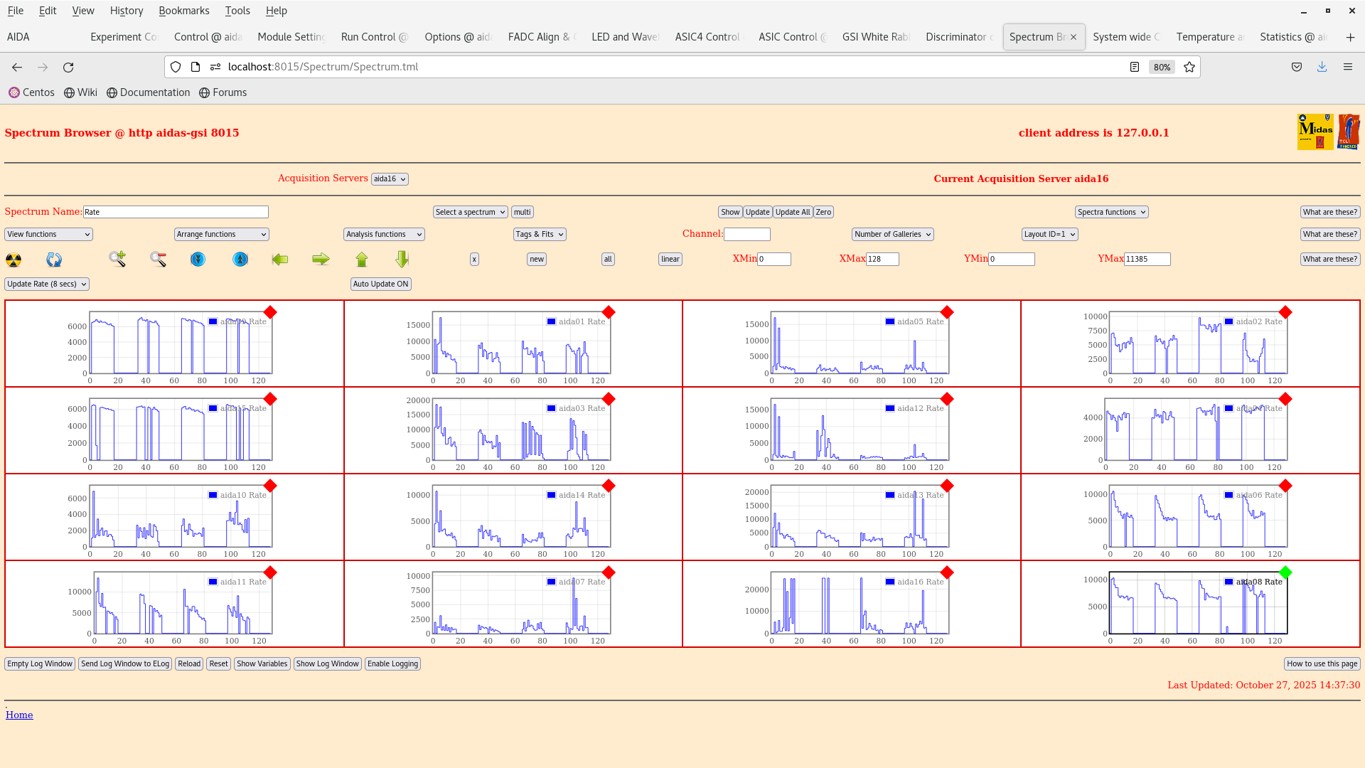
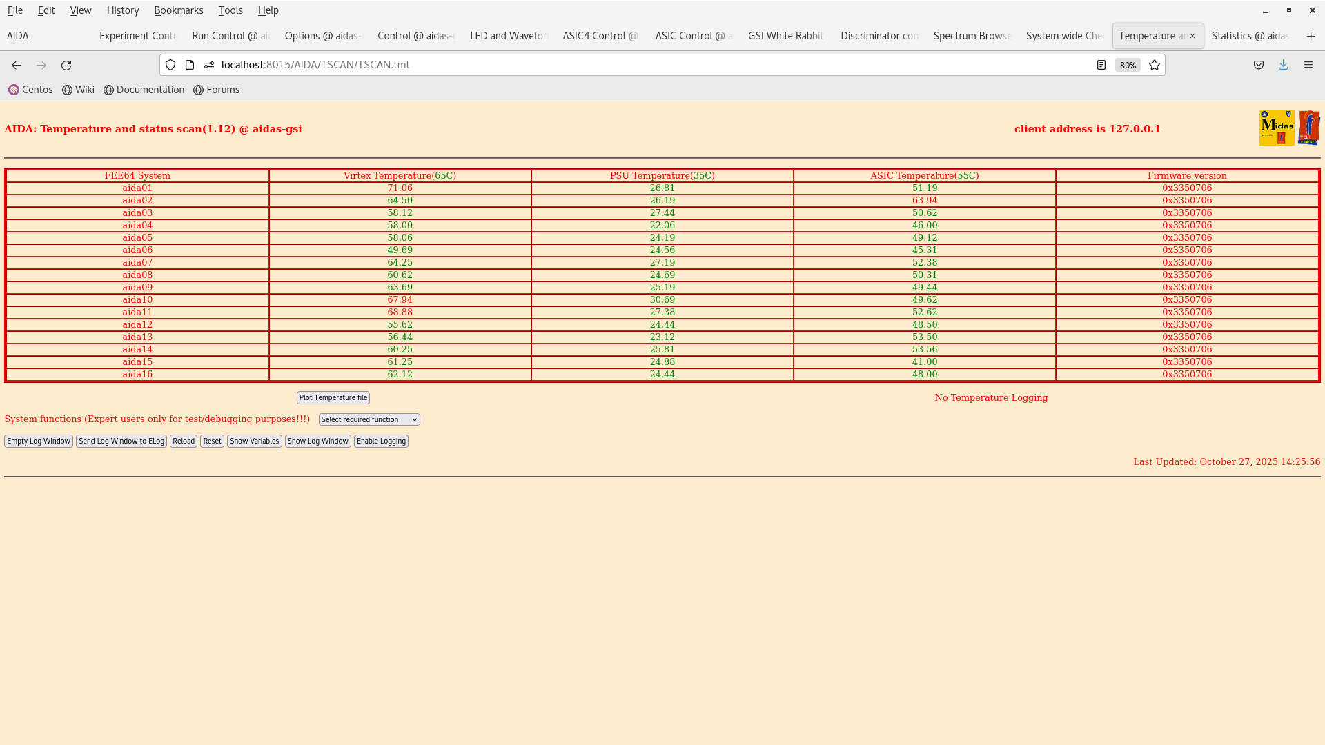
14:22 We are checking the noise conditions now. TEMPS OK. FADC Align and whiterabbit timestamps OK.

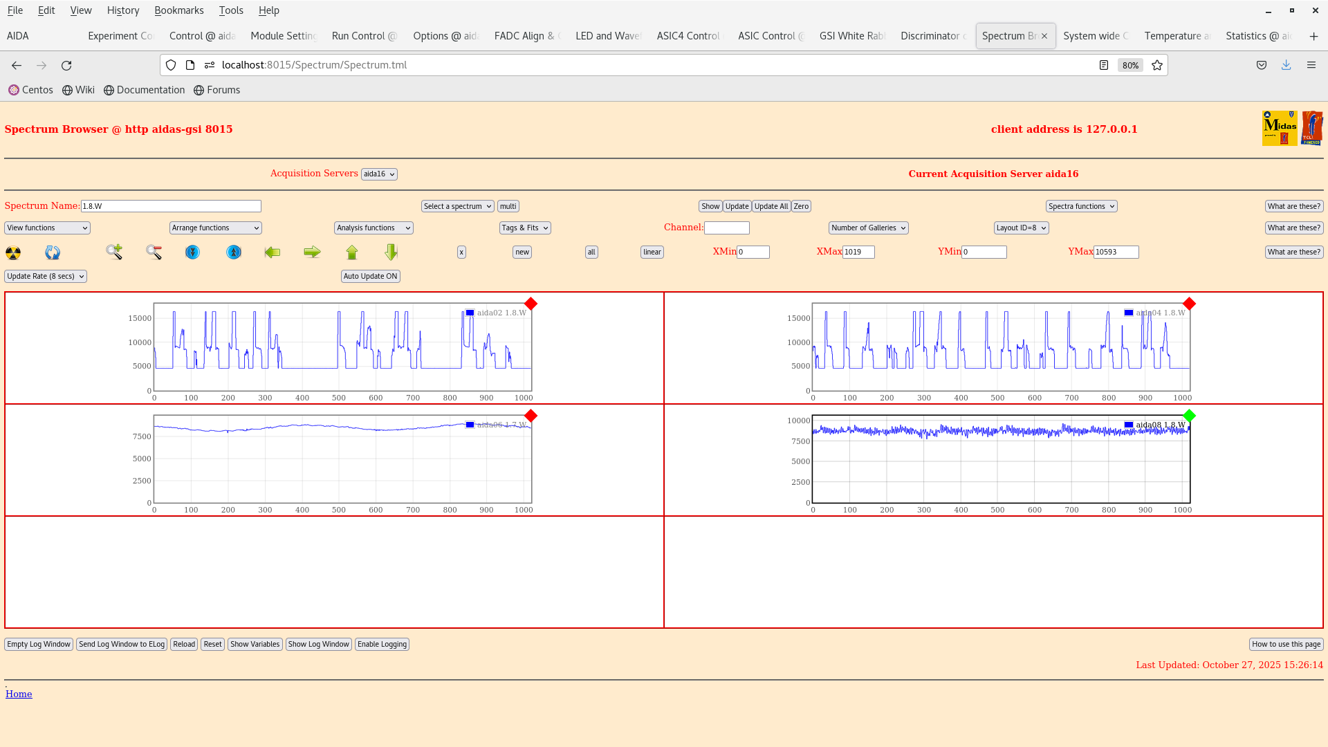
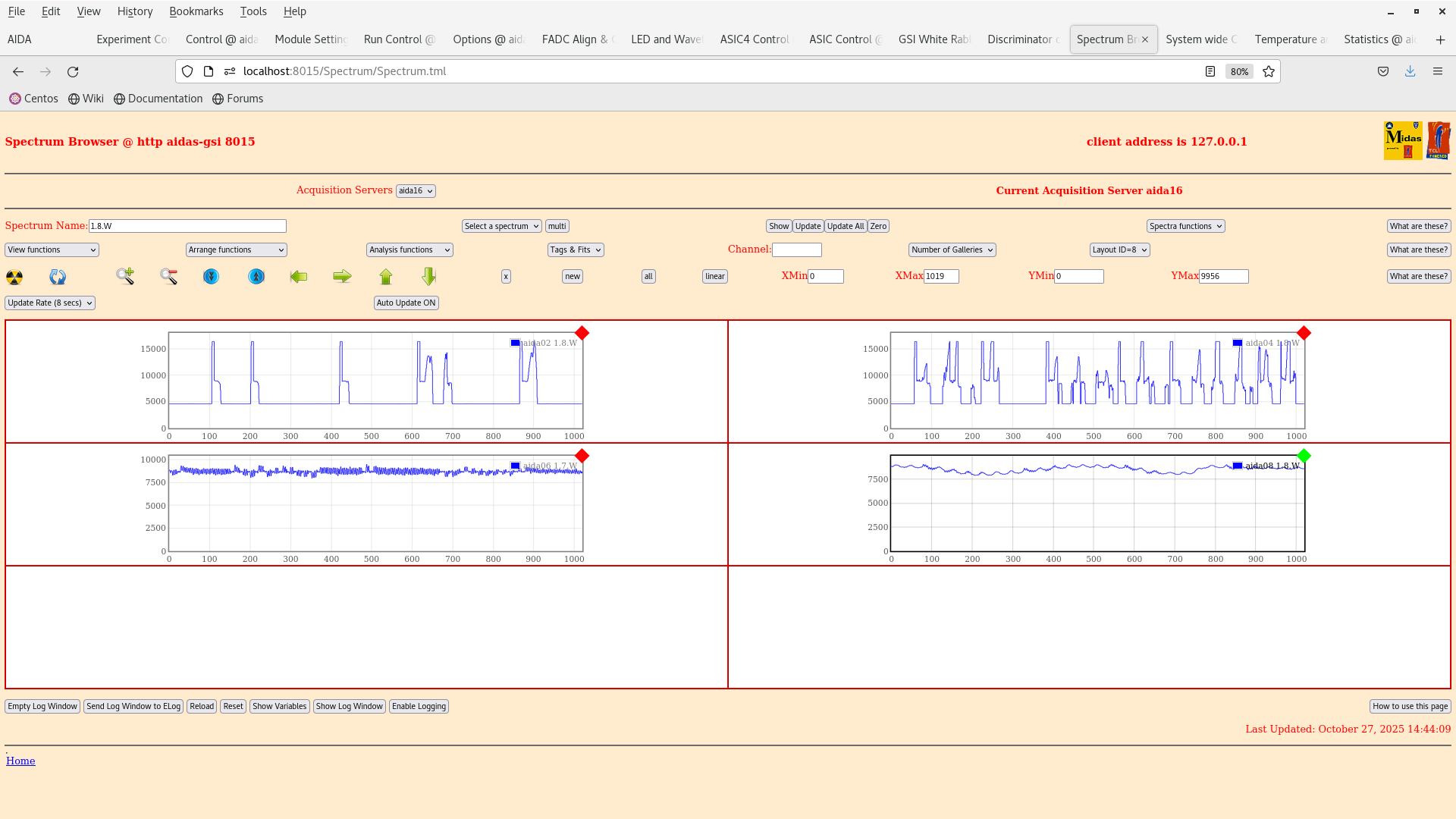
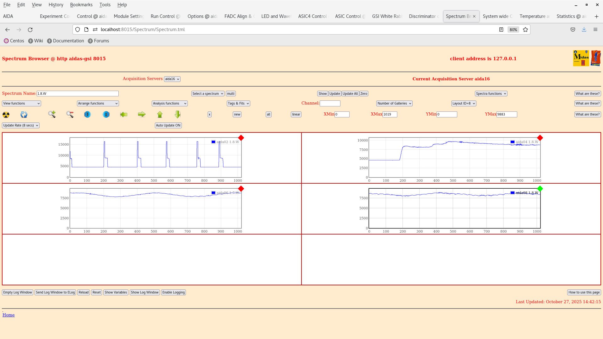
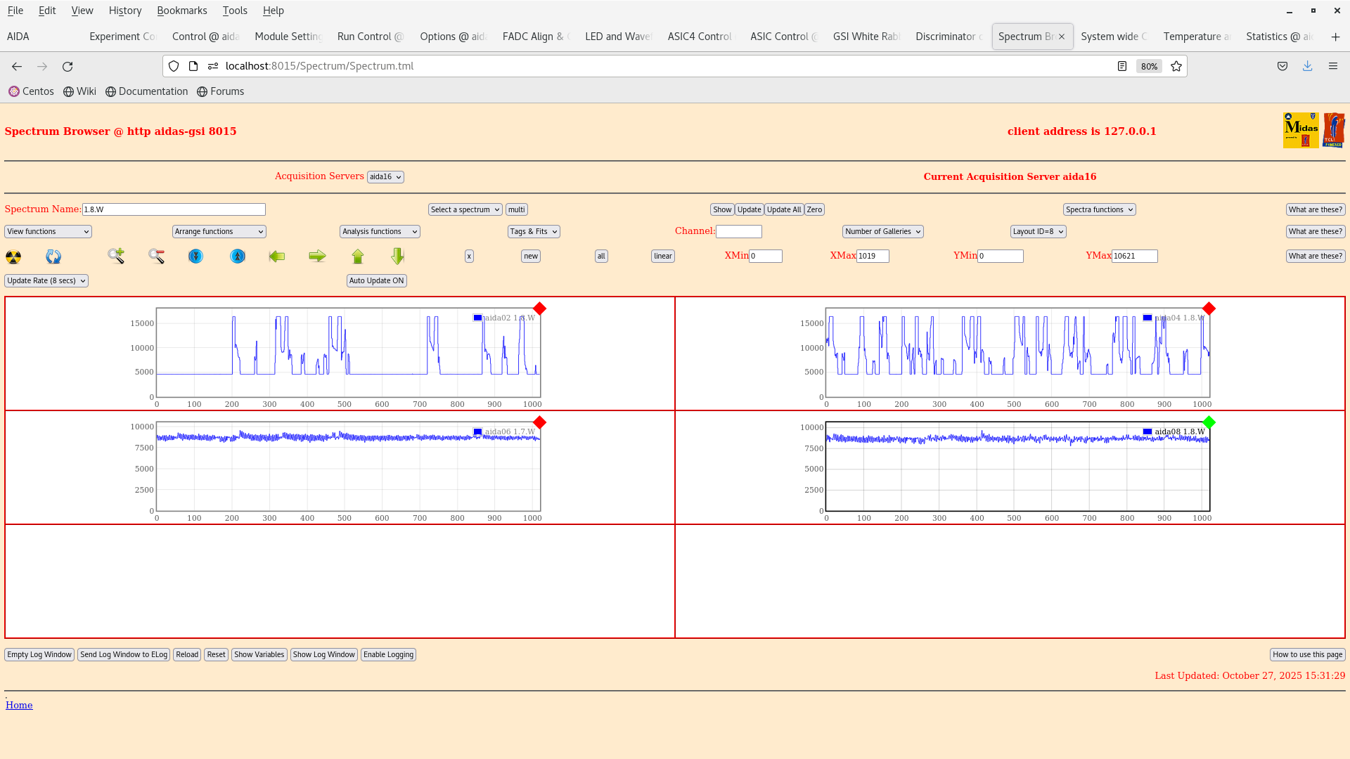
14:30 With the changes above we have noticed an intense 5/2 ms pulsed signal in the wave forms. See attachment 2

15:20 We decabled everything and the current scheme from 24102025, see prev. elog entry is in attachment 1.

15:34 We have unbiased AIDA1 and the wave forms improve for AIDA2 (?), 5/2 ms pulsed signal is still observed in AIDA1 |
|
.png.png)
|
|
|
|
|
|
|
|
|
|
|
|
|
|

|
|
|