| ID |
Date |
Author |
Subject |
|
465
|
Wed Nov 23 14:50:59 2016 |
Patrick Coleman-Smith | [ Info ] What does the System Wide Clock check mean when it fails. |
The System Wide check called "Check Clock Status" reads the status register from the FEE64 units in the system and compares the value of each bit against a template depending if the FEE64 is Master or not.
The bit fields have the following meaning :-
- clkd_ld1_pin. This is the "locked" status of the PLL in clock distribution chip LMK03200 #1. The clocks are used for the Waveform ADCs. ADCs 1 to 4 and FPGA Waveform decode logic.
- clkd_ld2_pin. This is the "locked" status of the PLL in clock distribution chip LMK03200 #2. The clocks are used for the Waveform ADCs. ADCs 5 to 8 and the Master SYNC PLL in the FPGA.
- aq_clock_locked. This is the "locked" status of the PLL in the FPGA. The clock is used for all data aquisition functions. If this isn't true ('1') then the module is not going to work as part of the system.
- sync_locked. This is the "locked" status of the PLL in the FPGA which provides a 200MHz clock to the SYNC pulse alignement logic. This is only used in the Master.
- to 31 read as '0'
The System Wide Check will only report the state of bits 0 to 2 but by opening the "Local Controls" browser window the status value can be seen ( after a reload ) at offset 1.
|
|
530
|
Wed Jan 18 14:16:47 2017 |
Patrick Coleman-Smith | Repaired Modules returning to RIKEN |
Five modules are being returned to RIKEN after repair.
The MAC addresses are :-
00:04:a3:2a:ED:8f
00:04:a3:2a:f6:d4
00:04:a3:2b:22:6e
00:04:a3:2b:33:15
00:04:a3:2a:d0:1a
00:04:a3:2b:33:0c
00:04:a3:2a:b6:45
00:04:a3:2a:b2:b2
00:04:a3:2b:09:da
00:04:a3:2b:11:c5
|
|
559
|
Mon May 8 10:00:02 2017 |
Patrick Coleman-Smith | [HowTo] Operating document for the Pi_Monitor FEE64 console logging equipment |
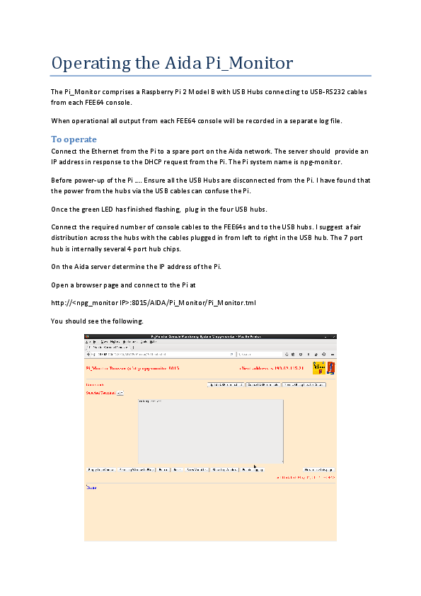
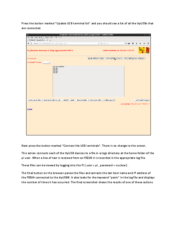
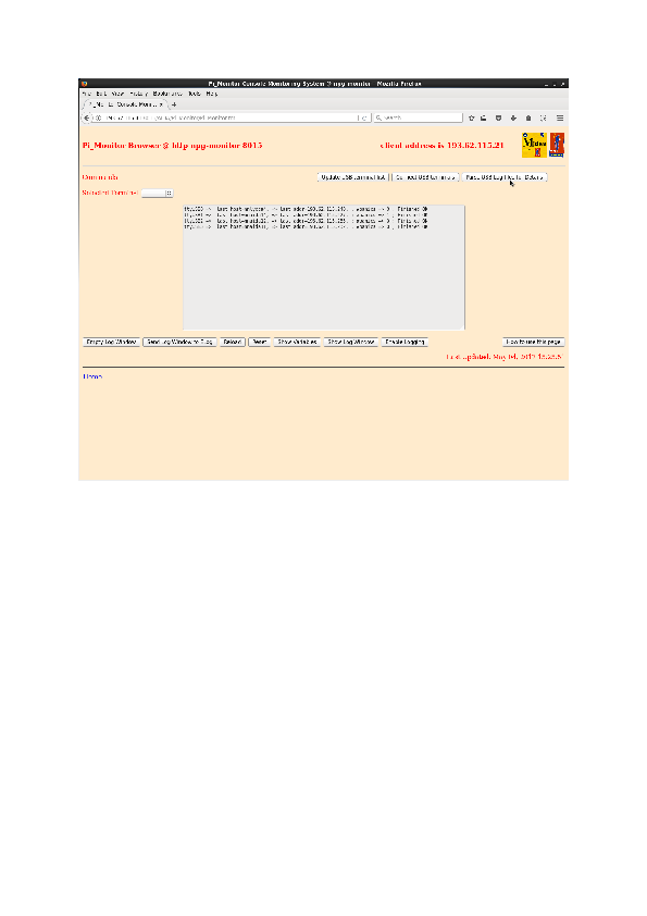
The operating proceedure for the Raspberry Pi FEE64 console monitor is attached.
Please let me know if more detail is required.
|
| Attachment 1: Operating_the_Aida_Pi_Monitor.pdf
|
|
|
575
|
Thu May 18 15:20:44 2017 |
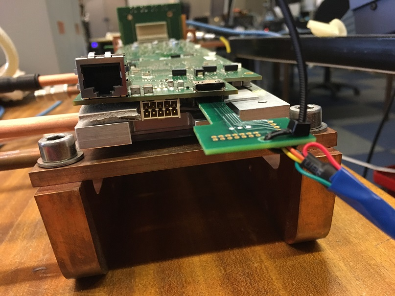
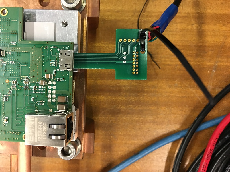
Patrick Coleman-Smith | [HowTo] Connecting a USB console interface to the FEE64 |
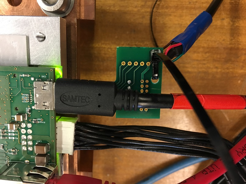
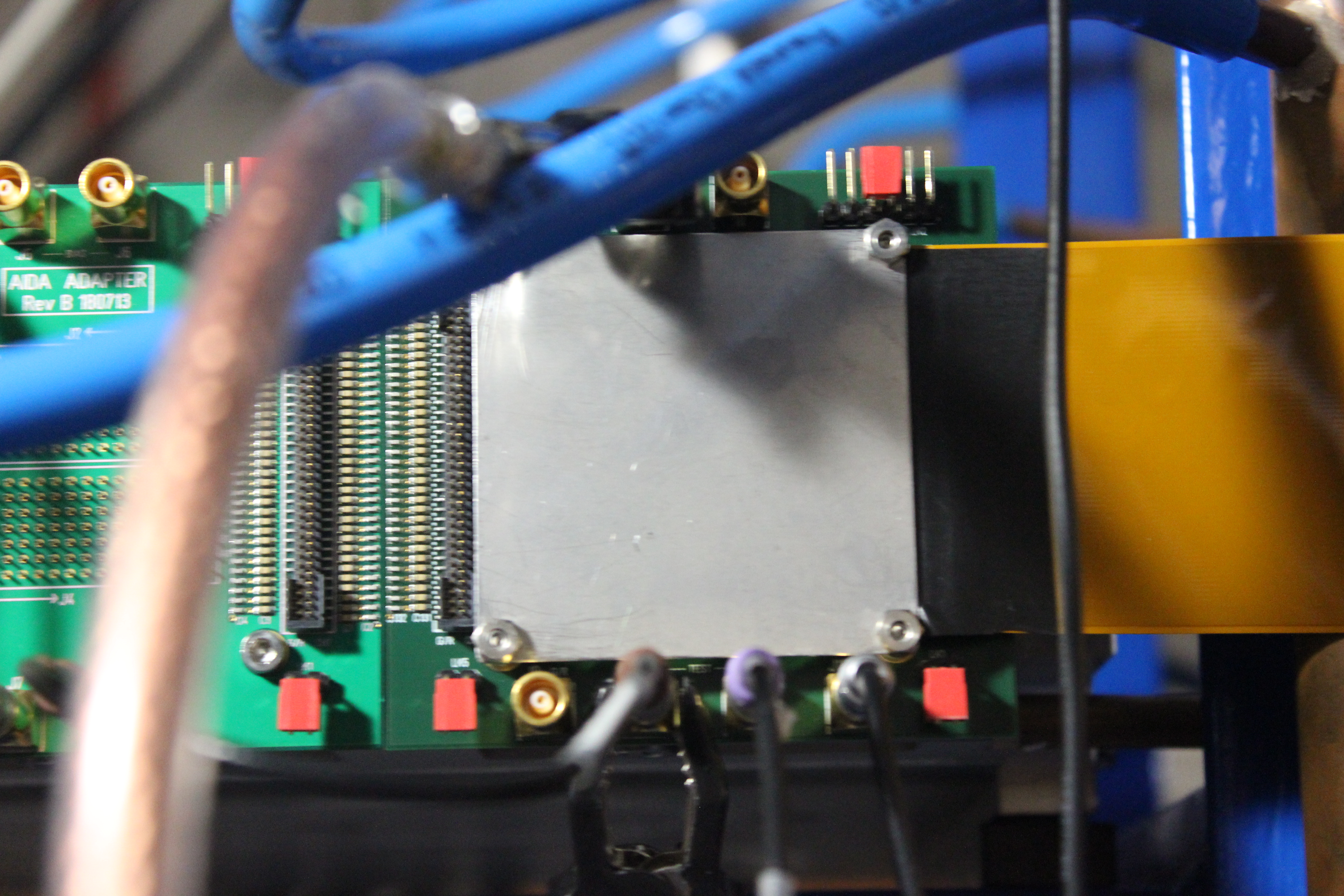
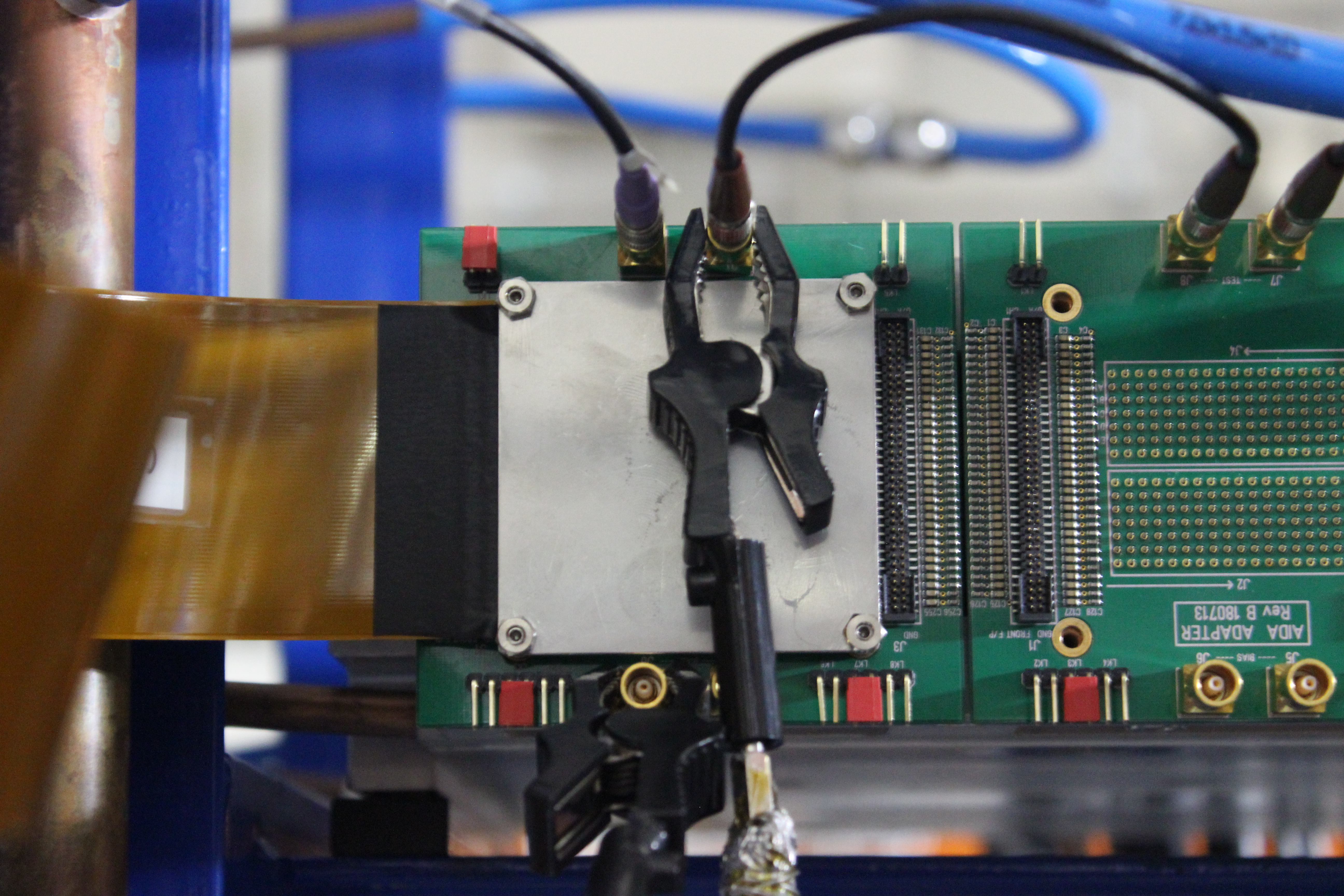
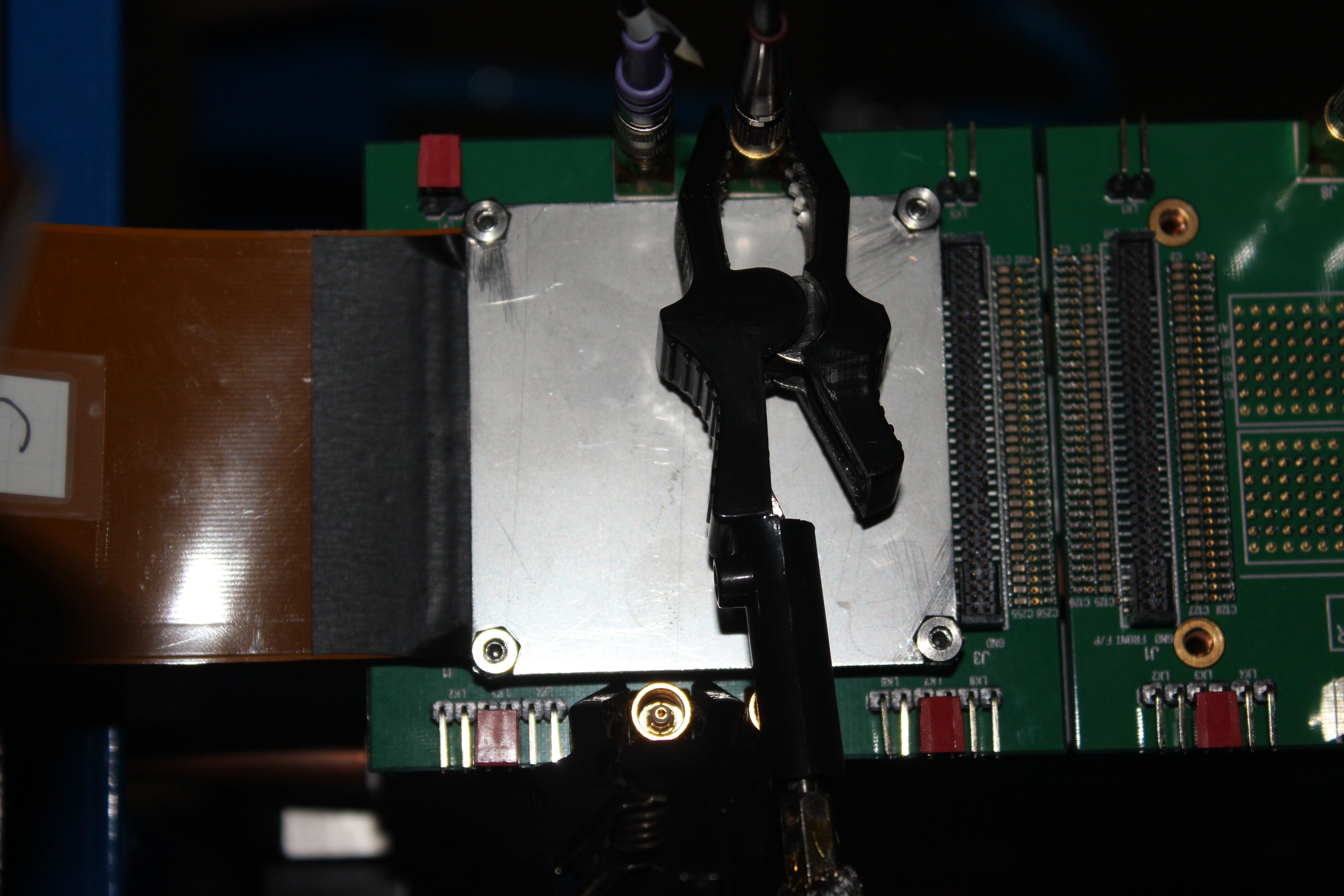
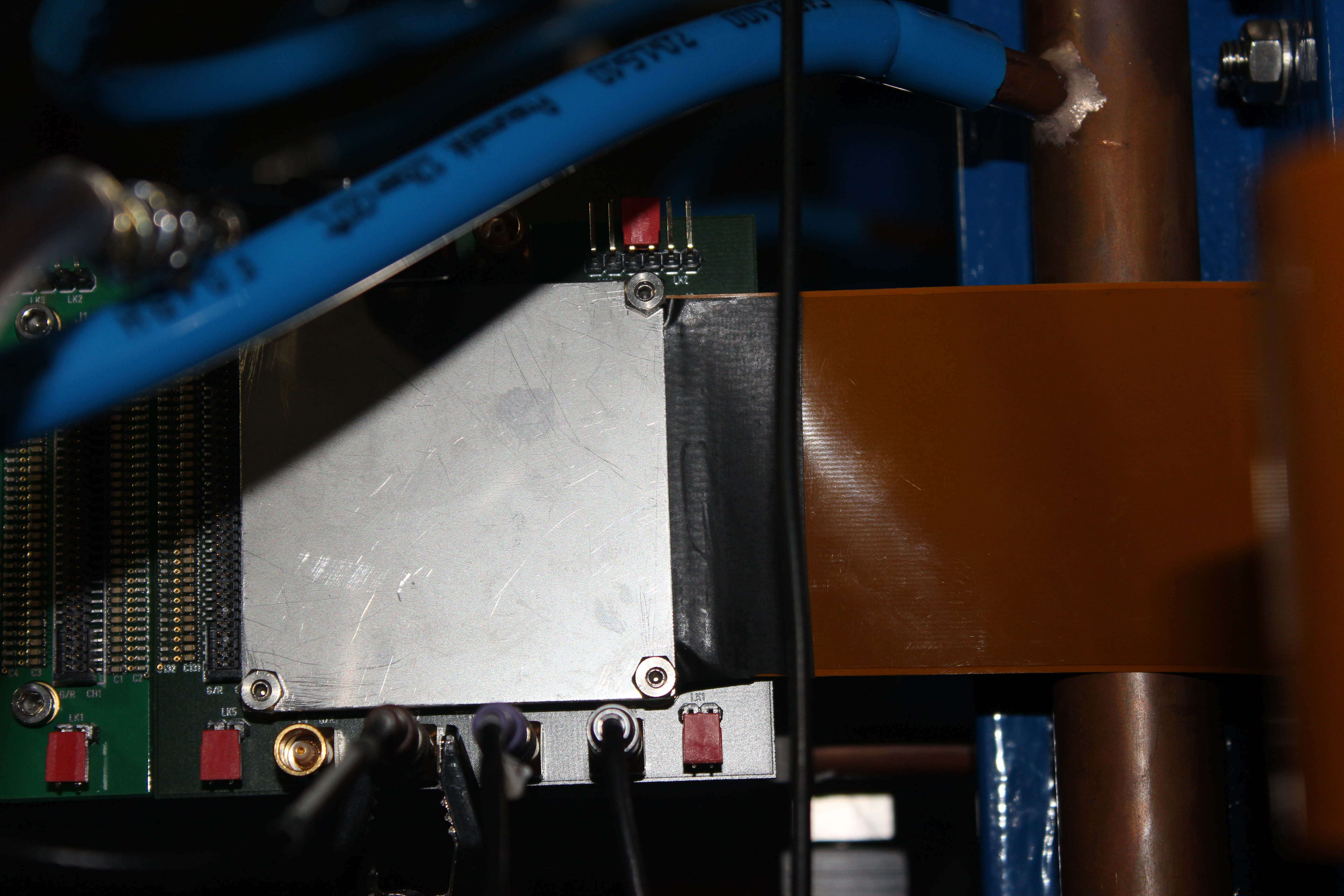
The three attachments show the orientation of the console cable pcb relative to the FEE64 connectors.
The first with the other cables and the other two with no cables for clarity of position. |
| Attachment 1: IMG_0107_resize.jpg
|
|
| Attachment 2: IMG_0108_resize.jpg
|
|
| Attachment 3: IMG_0109_resize.jpg
|
|
|
595
|
Wed May 24 13:39:12 2017 |
Patrick Coleman-Smith | Examination of Console Logs -- and a couple of reminders |
I have tarred and zipped all 24 logs and shipped them back to the UK. Now I can browse through them.
Studying the "panics" :=
nnaida17 has one which is an NFS mount failure.
nnaida20 and 22 have one each which are "Starting midas: Page fault in user mode with in_atomic() = 1 mm = c61bf200" but with different values for the mm=.
I am studying the web to understand why this may occur in a particular program. Both occur at similar places after "Starting midas".
There are reports of "Clock not locked. status = 0xc" during Setup Electronics which is a bit unusual. These occur in nnaida4, 17 and 22.
Also "Clock not locked. status = 0xd" in nnaida23,17,3,19,6,5,14,7,9. Further investigation to understand all these.
The bit allocation of the Clock Status word is:-
Bit 0 : Lock Detect bit from LMK03200 #1
Bit 1 : Lock Detect bit from LMK03200 #2
Bit 2 : Lock detect from the internal DCM for the mux clock.
Bit 3: iDelay ready signal
The LMK03200 are the two PLLs which are connected to the 50MHz input clock. The clock setup in the log directly before the error report for nnaiad17 had reported correctly setup and the ADCs had calibrated, these rely on a stable 50MHz from the LMK03200s.
I have also spotted some diagnostic information about the waveform readout that is useful.
Just a reminder..... when power cycling the equipment please leave the power off for at least 10 seconds to allow all the capacitors in the supply chain to discharge.
Also note that the console monitor window in the Pi can be used to check that all FEE64s have "finished" the power-on sequence by using the "parse" button.
Since it doesn't use the DAQ software it won't lock-up and it will give an indication of progress. |
|
597
|
Wed May 24 14:51:06 2017 |
Patrick Coleman-Smith | Examination of Console Logs -- and a couple of reminders |
| Quote: |
|
I have tarred and zipped all 24 logs and shipped them back to the UK. Now I can browse through them.
Studying the "panics" :=
nnaida17 has one which is an NFS mount failure.
Do we understand why? Are there different/additional NFS mount options to be considered?
nnaida20 and 22 have one each which are "Starting midas: Page fault in user mode with in_atomic() = 1 mm = c61bf200" but with different values for the mm=.
I am studying the web to understand why this may occur in a particular program. Both occur at similar places after "Starting midas".
There are reports of "Clock not locked. status = 0xc" during Setup Electronics which is a bit unusual. These occur in nnaida4, 17 and 22.
Also "Clock not locked. status = 0xd" in nnaida23,17,3,19,6,5,14,7,9. Further investigation to understand all these.
The bit allocation of the Clock Status word is:-
Bit 0 : Lock Detect bit from LMK03200 #1
Bit 1 : Lock Detect bit from LMK03200 #2
Bit 2 : Lock detect from the internal DCM for the mux clock.
Bit 3: iDelay ready signal
The LMK03200 are the two PLLs which are connected to the 50MHz input clock. The clock setup in the log directly before the error report for nnaiad17 had reported correctly setup and the ADCs had calibrated, these rely on a stable 50MHz from the LMK03200s.
I have also spotted some diagnostic information about the waveform readout that is useful.
Just a reminder..... when power cycling the equipment please leave the power off for at least 10 seconds to allow all the capacitors in the supply chain to discharge.
We do - standard procedure is to wait 20s.
Also note that the console monitor window in the Pi can be used to check that all FEE64s have "finished" the power-on sequence by using the "parse" button.
Since it doesn't use the DAQ software it won't lock-up and it will give an indication of progress.
We do check for further panics. I assume we would have to read each system log to check that the boot sequence and app load had completed?
|
|
|
598
|
Wed May 24 15:58:53 2017 |
Patrick Coleman-Smith | Examination of Console Logs -- and a couple of reminders |
| Quote: |
|
| Quote: |
|
I have tarred and zipped all 24 logs and shipped them back to the UK. Now I can browse through them.
Studying the "panics" :=
nnaida17 has one which is an NFS mount failure.
Do we understand why? Are there different/additional NFS mount options to be considered? Investigations ongoing :-)
nnaida20 and 22 have one each which are "Starting midas: Page fault in user mode with in_atomic() = 1 mm = c61bf200" but with different values for the mm=.
I am studying the web to understand why this may occur in a particular program. Both occur at similar places after "Starting midas".
There are reports of "Clock not locked. status = 0xc" during Setup Electronics which is a bit unusual. These occur in nnaida4, 17 and 22.
Also "Clock not locked. status = 0xd" in nnaida23,17,3,19,6,5,14,7,9. Further investigation to understand all these.
The bit allocation of the Clock Status word is:-
Bit 0 : Lock Detect bit from LMK03200 #1
Bit 1 : Lock Detect bit from LMK03200 #2
Bit 2 : Lock detect from the internal DCM for the mux clock.
Bit 3: iDelay ready signal
The LMK03200 are the two PLLs which are connected to the 50MHz input clock. The clock setup in the log directly before the error report for nnaiad17 had reported correctly setup and the ADCs had calibrated, these rely on a stable 50MHz from the LMK03200s.
I have also spotted some diagnostic information about the waveform readout that is useful.
Just a reminder..... when power cycling the equipment please leave the power off for at least 10 seconds to allow all the capacitors in the supply chain to discharge.
We do - standard procedure is to wait 20s.
Also note that the console monitor window in the Pi can be used to check that all FEE64s have "finished" the power-on sequence by using the "parse" button.
Since it doesn't use the DAQ software it won't lock-up and it will give an indication of progress.
We do check for further panics. I assume we would have to read each system log to check that the boot sequence and app load had completed?
If you do the parse before any action like RESET or SETUP the parse looks for the last line being the expected one which is :-
"Completed custom startup from /MIDAS/TclHttpd/Html/AIDA/RunControl/stats.defn.tcl"
When found the report from the parse will end with Finished OK for each FEE
|
|
|
|
15
|
Thu Oct 2 15:23:38 2014 |
Patrick Coleman-Smith and Chris Griffin | Trial with Filtered AIDA PSU |
Assembled three more of the filter boards and installed them in the AIDA PSU with the first, wired to use the switchmode power supply.
Powered up nnaida14 first and went fine. Just the boot sequence and measure the voltages for stability.
Powered up the remainder and all was well.
Setup and go..... the rates were way too high in all of them.
nnaida12 was running at 200k/sec+ most of the time.
The other three could be reduced in rate by changing the slow comp thresh as would be expected but 12 wasn't any good.
Tried:
Remove MACB HDMI.... no good
isolate psu earth from NIM crate ( put psu on foam support ) ..... no good
Checked the filter output and the sine wave reported yesterday ( nnaida2 ) was present on all voltage rails but no evidence of high frequency noise.
Set all channels to 1GeV, with Slow comp thresh of 10, and 11,13 & 14 showed roughly the same rate of 10 to 15k/sec. Peaks in the spectra were FWHM 12 at a random sample. nnaida12 would not conform.
Changed back to the bench power supply connections so Chris can continue. |
|
17
|
Fri Oct 24 15:05:28 2014 |
Patrick and Alfredo | new VHDL: FEE_Riken_Apr14_21.bin |
New VHDL loaded in NNAIDA#11,#12,#13,#14: /MIDAS/Aida/FEE_Riken_Apr14_21.bin
The code introduces the feature of turning ON or OFF individual ASICs in a FEE64 card. This is achieved by turning off the clock signal to a individual ASIC, which then will not produce any data.
Feature controled through "ASIC readout bugger and control", by register onn base address 0x300 and offset 7 (until now 'ASIC readout enable').
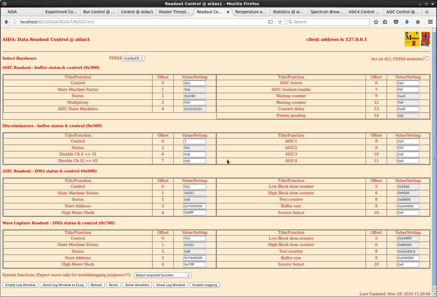
Only basic tests of new VHDL were done, but the system seems to be working as before and the operation of turning off individual ASICs works as expected. Screenshot is sample of turning off ASIC3 in NNAIDA#12.
|
|
244
|
Sat May 28 07:31:07 2016 |
Saturday 8 May 2016 | TD, CG |
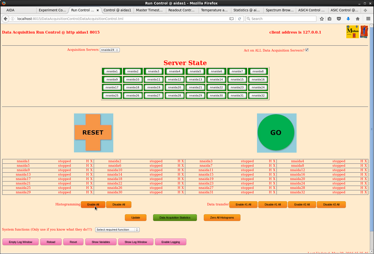
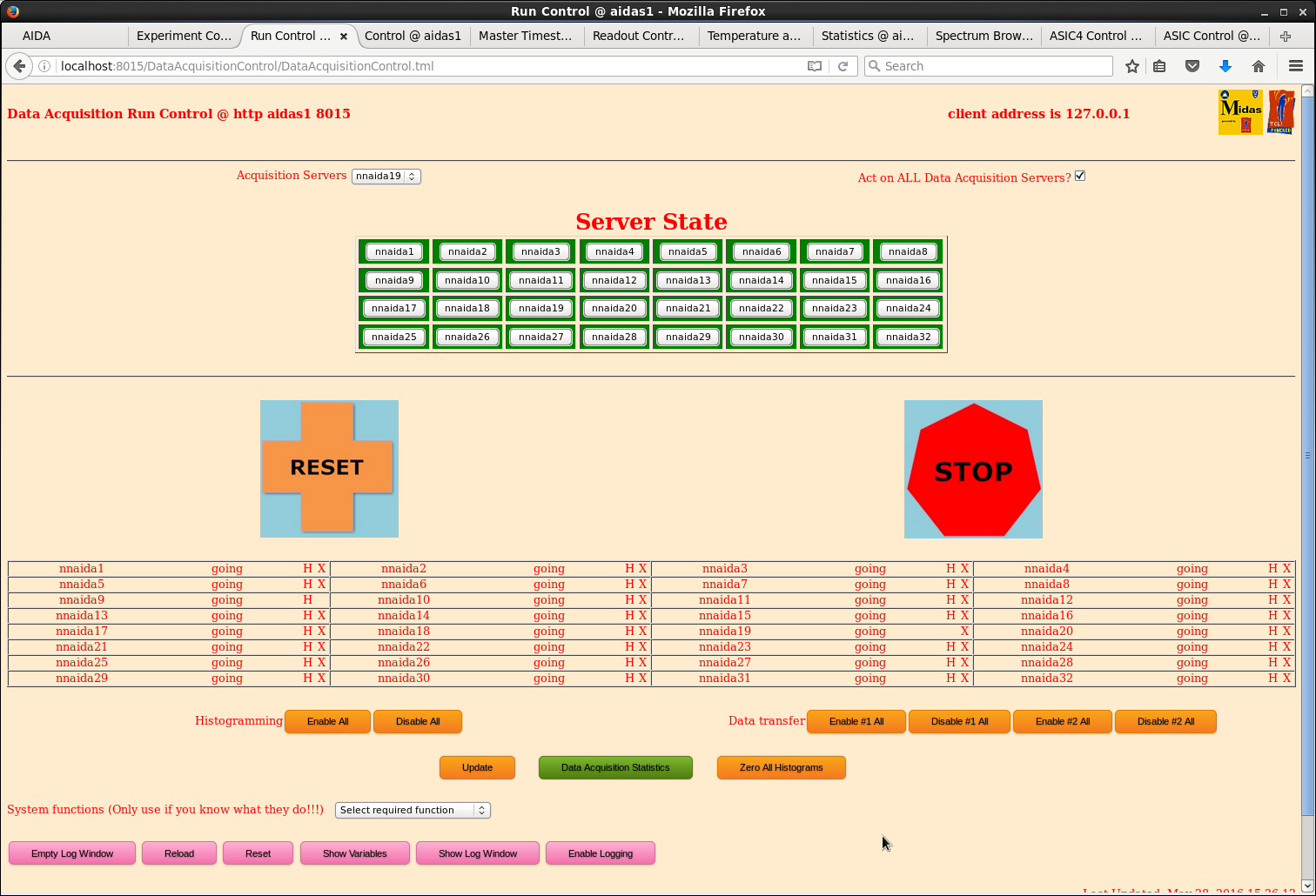
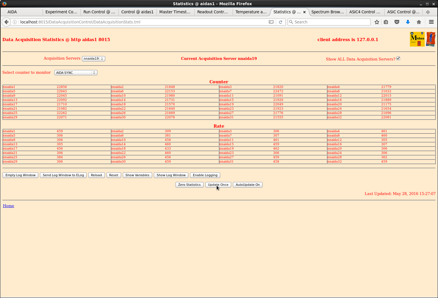
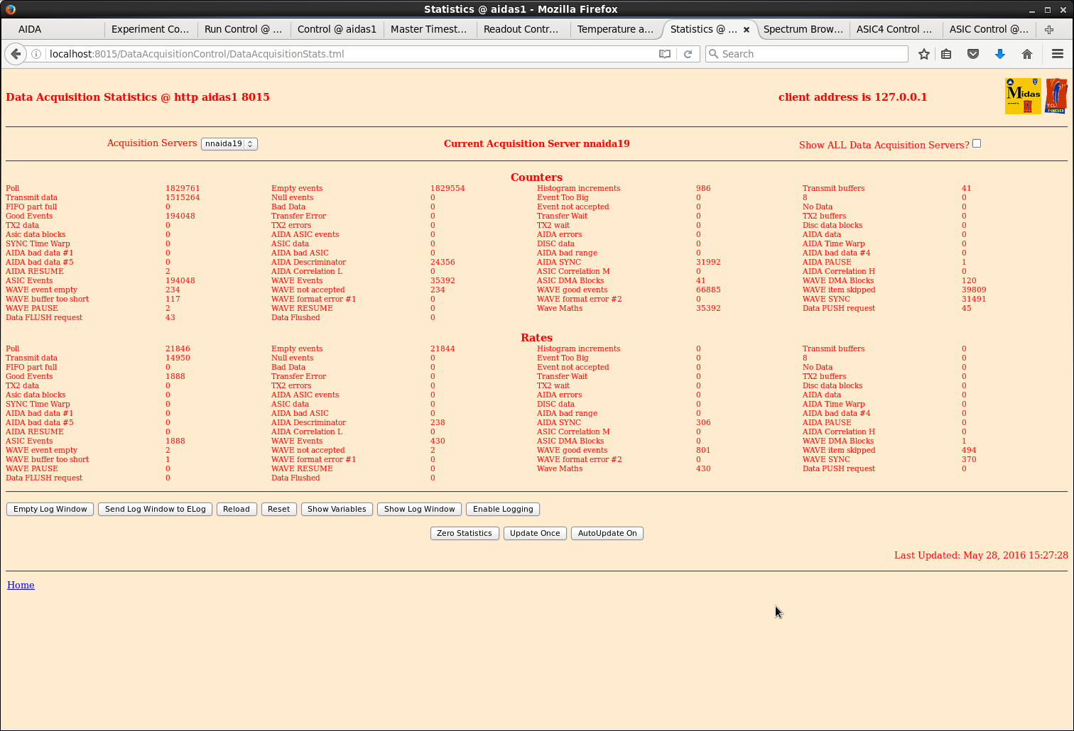
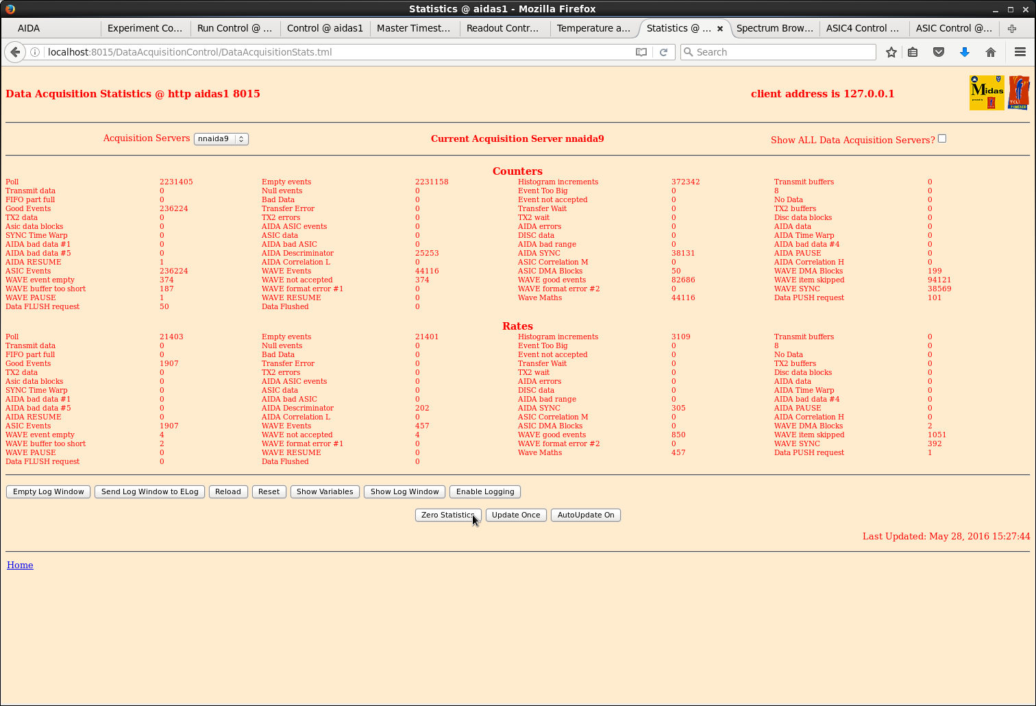
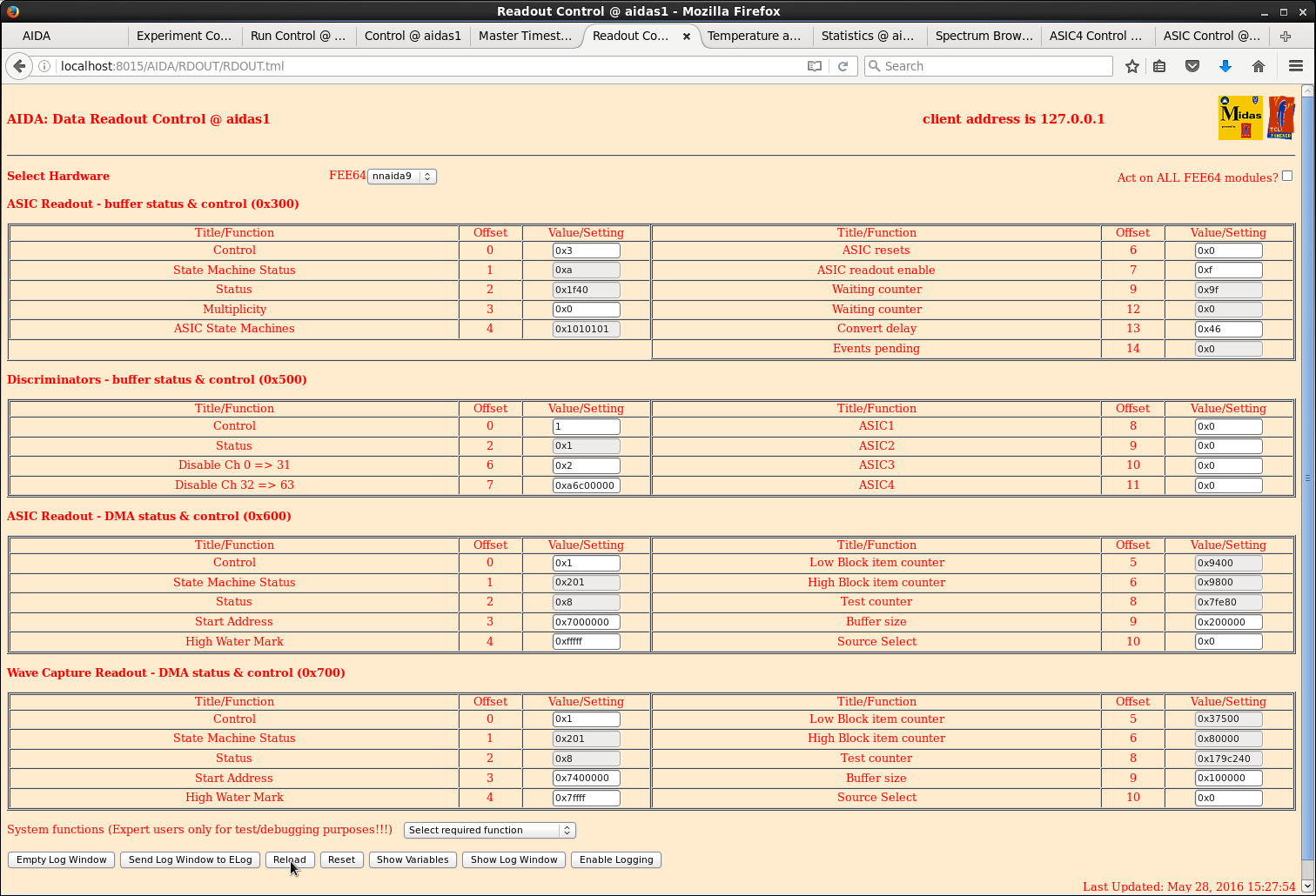
15.20 DAQ histogramming & data transfer #1 enabled
      Merger configured, started, input paused
      Following DAQ GO nnaida9 data transfer 'X' nnaida19 histogramming 'H' disappear - see attachments 1-7

      Workaround suggested by https://elog.ph.ed.ac.uk/AIDA/230 appear not to work


16.25 Resolved data transfer issue
      nnaida9 producing SYNCs but merger data queue blocked
      rebooted aidas1

      nnaida19 histogramming issue remains

17:50 6 DSSD insalled

      From front to back of stack:

      DSSD 1 = 3131-9
           2 = 3058-25 (rotated 90deg w.r.t. other detectors - p-strips horizontal and n-strips vertical)
           3 = 2998-23
           4 = 3058-5
           5 = 3058-6
           6 = 3058-7

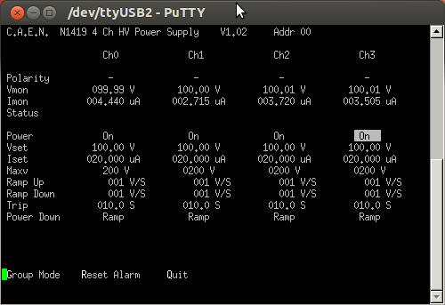
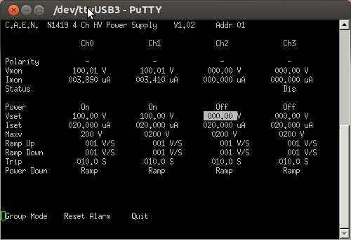
      HV mapping (-ve bias):

        DSSD     Braid      Core
          1     nnaida20   nnaida17
          2     nnaida19   nnaida18
          3     nnaida12   nnaida14
          4     nnaida11   nnaida13
          5     nnaida4    nnaida6
          6     nnaida3    nnaida5

18.55 Change ASIC settings

      nnaida18, nnaida21 positive -> negative input
                         diode link threshold 0xca -> 0xbf
                         LED settings negative -> positive, threshold 7200 -> 9000

      nnaida19, nnaida24 negative -> positive input
                         diode link threshold 0x11 -> 0x23
                        LED settings positive -> negative, threshold 9000 -> 7200

      Saved new settings to DB key 2016May28-18.52.07
Saved new DB key to Options |
| Attachment 1: 50.png
|
|
| Attachment 2: 51.png
|
|
| Attachment 3: 52.png
|
|
| Attachment 4: 53.png
|
|
| Attachment 5: 54.png
|
|
| Attachment 6: 55.png
|
|
| Attachment 7: 56.png
|
|
| Attachment 8: caen_remote_0.png
|
|
| Attachment 9: caen_remote_1.png
|
|
|
32
|
Sun Feb 15 22:30:48 2015 |
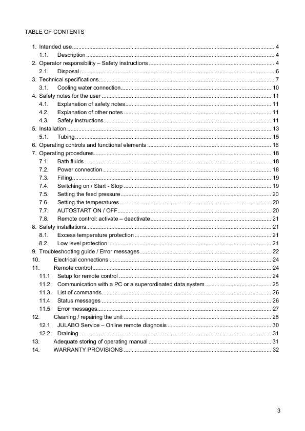
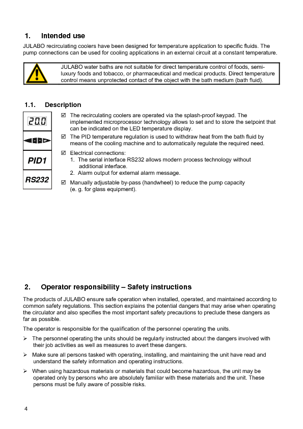
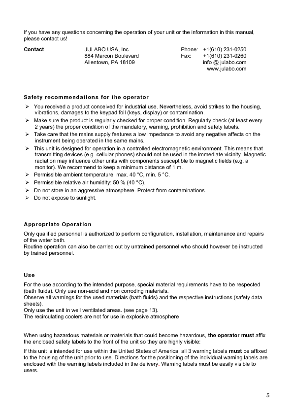
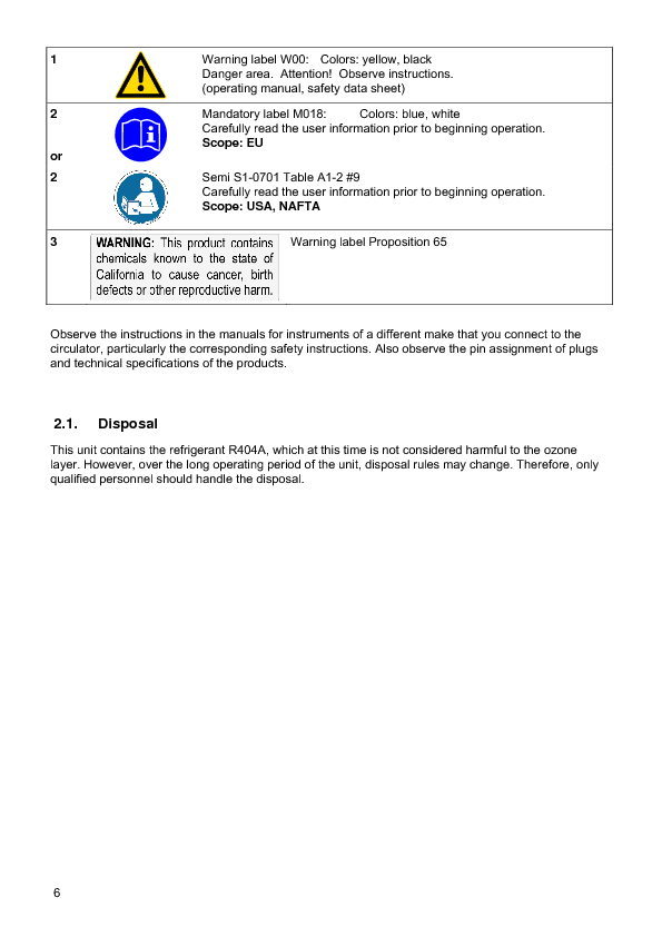
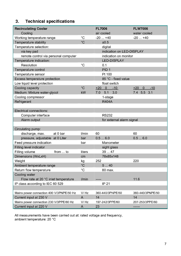
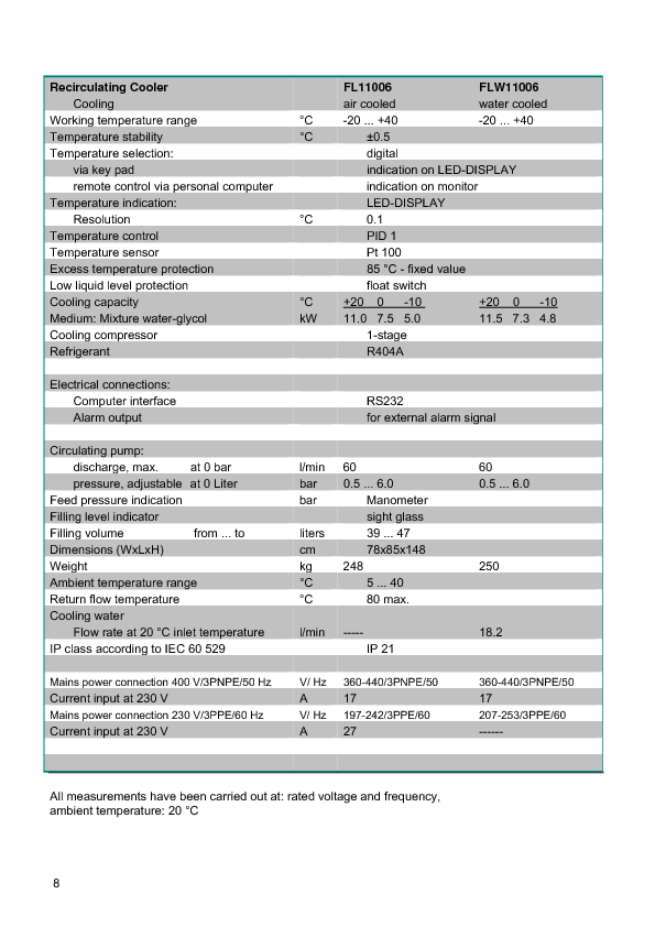
TD | Julabo FL11006 Operating Manual |
|
| Attachment 1: Julabo_FL11006.pdf
|
|
|
42
|
Fri Feb 20 10:48:09 2015 |
TD | How To Connect the FEE64 System Console Using PuTTY |
Set permissions for the USB-serial device using the command

sudo chmod 777 /dev/ttyUSB0

Note: Vic Pucknell reports that he has sometime observed the device
rotate between /dev/ttyUSB0, /dev/ttyUSB1, /dev/ttyUSB2 etc - make\
sure you are using the correct device name with the command:

ls -l /dev/ttyUSB*


Start PuTTY

Select Connection Type 'Serial'
Enter Serial Line (/dev/ttyUSB0 or /dev/ttyUSB1)
Enter speed (9600)
Select 'Open'

Note: permissions for the USB-serial device will revert to their
default (mode 440) when the OS notices the change but by then
the serial line connection will have been established. |
|
47
|
Mon Feb 23 11:10:44 2015 |
TD | Outline test plan - RIKEN - Feb 2015 |
With the exception of one AIDA FEE64 PSU configuration test (5) and the upgrades
of the AIDA FEE64 firmware (8) and MIDAS DAQ software (9) we have now completed all
of tasks described in the outline plan. |
| Attachment 1: RIKEN_test_-_Feb_2015.txt
|
Outline test plan - RIKEN - Feb 2015

1) Move Julabo FL006 recirculating chiller (plus ac mains transformer)
   and AIDA assembly stand into position.

   Consult Shunji Nishimura
   If we move equipment for the test, do we have to move it back before we leave?

2) Check 3-phase connection to ac mains transformer. Check chiller POST.

   TD - upload images from April/May 2014 to Elog

3) Re-connect Julabo FL006 recirculating chiller to AIDA assembly.
   Inspect coolant loop. Check coolant levels. Start chiller.
   Inspect for leaks. Check coolant levels.

4) Replace faulty USB-controlled ac mains switch. Test operation with
   FEE modules disconnected.

5) Connect 8x FEE modules to ?x FEE PSUs.

   PCS - default initial configuration?

6) Check MACB cabling. Power up 8x FEE modules.

7) Check setup & configuration (ASICs, FEE64).
   Default ASIC parameters (tau = 2us). Waveforms off.

8) Test FEE64 performannce with pulser and no input load.
   Expect pulser peak width < 15 ch FWHM.

*** Status quo ante re-established ***


Test 1

1) Install 1x MSL type BB18-1000 DSSSD with 3x modified 0.9m Kapton PCBs
   plus 1x unmodified 0.9m Kapton PCB. Install 207Bi source.

2) Bias DSSSD using Silena 7710 Quad Bias Supply (ground referenced bias)
   and confirm stability problems observed April/may 2014 are still present.

Test 2

1) Bias DSSSD using CAEN N1419B (floating bias) and confirm stability problems
   improve. Assess impact of preAmp reference setting - if possible, proceed
   with default setting.

2) Test FEE64 performance with pulser.
   Expectation pulser peak width < 120-150 ch FWHM.

Test 3

1) Adjust FEE64 PSU voltage levels per procedure described by PCS.

2) Test FEE64 performance with pulser. Compare to previous test.

Test 4

1) Attach heavy-duty grounding cable between FEE adaptor PCBs.

2) Test FEE64 performance with pulser. Compare to previous tests.

Test 5

1) Re-configure FEE PSU cabling per PCS request(s)

2) Test FEE64 performance with pulser. Compare to previous tests.

Test 6

1) Re-assess impact of preAmp reference setting.

Test 7

1) With optimum configuration obtain and analyse data files with pulser
   and 207Bi data.

Test 8

1) Update FEE firmware. Repeat test 7.

Test 9

1) Update MIDAS software. Repeat test 7.
|
|
51
|
Thu Mar 5 12:11:44 2015 |
TD | To Do list - March 2015 |
A draft 'to do' list in preparation for further AIDA tests at RIKEN from mid-April.

Please feel free to add your comments, suggestions, other items etc.


High Priority

- [VP] fix problem with new merger program which crashes (SEGV) at startup
  see https://elog.ph.ed.ac.uk/AIDA/48

- [PCS/Edinburgh] fit 4x AIDA FEE64 PSUs with LCR filters and return to RIKEN

- [PM] transfer AIDA support assembly from original base to new RIKEN F11 base

Medium Priority

- [VP] TapeServer 'no storage' mode should not create files (cf. MIDAS VME DAQ TapeServer behaviour) ... ?

- [VP] TapeServer should check for existence of file before opening new file
  (and possibly overwriting an existing file) as a workaround for umode 022 file perms

- [VP] Define robust procedure for starting/stopping MIDAS DAQ/Merger/TapeService

- [VP/PCS] Critically review data synchronisation methodology
  see https://elog.ph.ed.ac.uk/BRIKEN/5 and https://elog.ph.ed.ac.uk/BRIKEN/6

Low Priority

- [Edinburgh] modify USB ac mains switches - relays default to off state - ship to RIKEN

- [Edinburgh] purchase 3x 3TB SATA disks for installation in aidas1 |
|
53
|
Mon Mar 9 13:59:32 2015 |
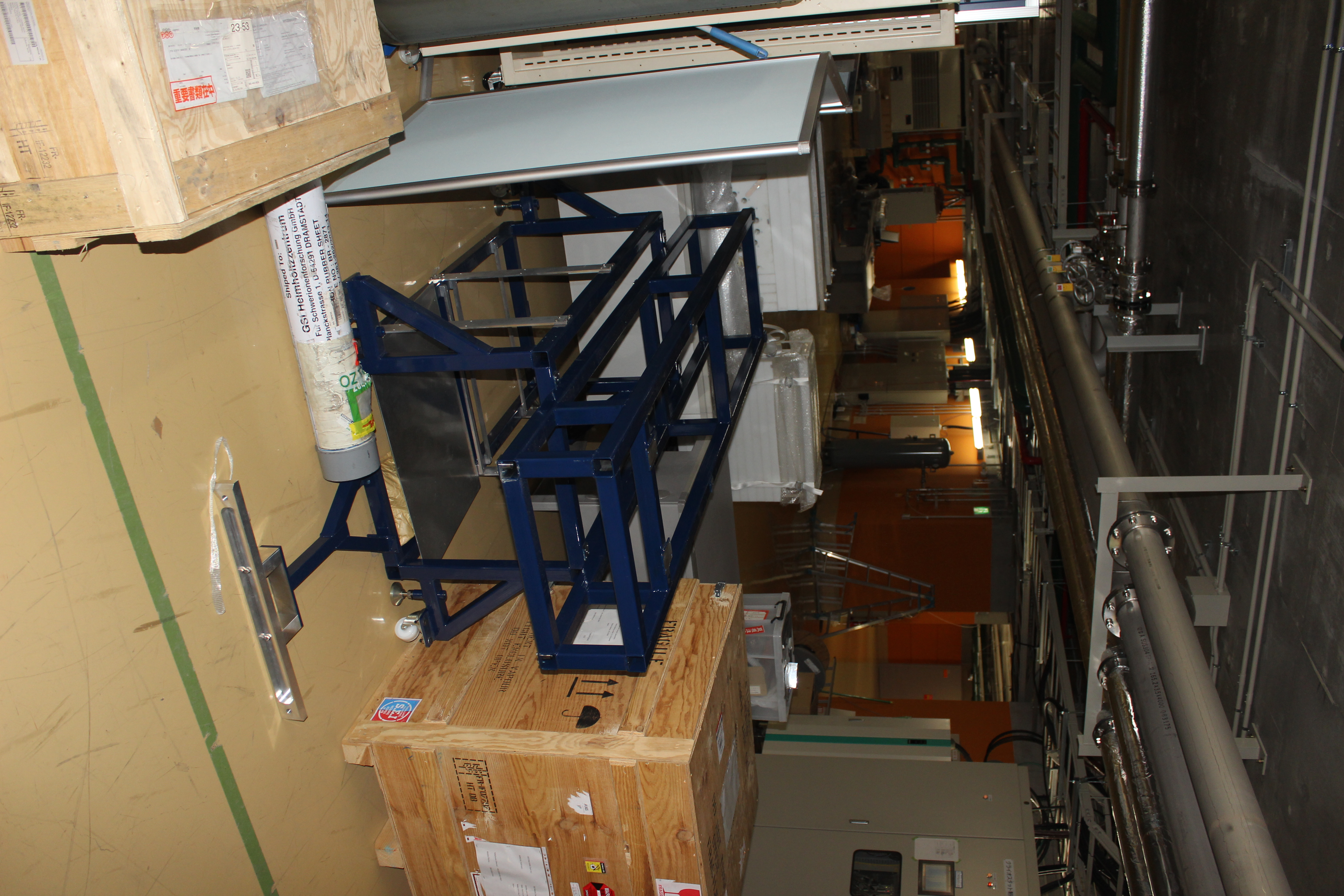
TD | New AIDA support frame for F11/F12 @ RIKEN |
|
| Attachment 1: IMG_2798.JPG
|
|
|
55
|
Mon Mar 9 16:51:26 2015 |
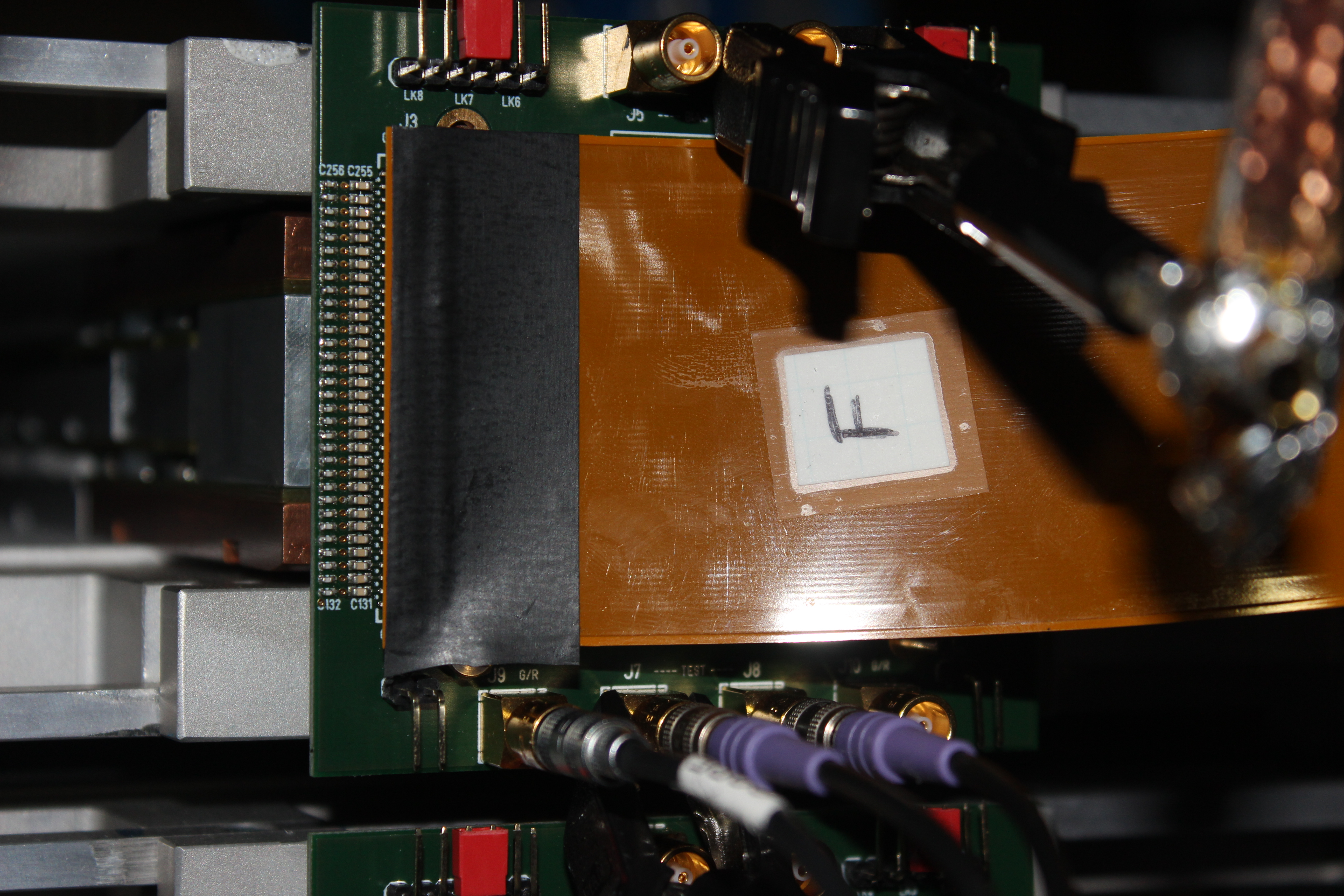
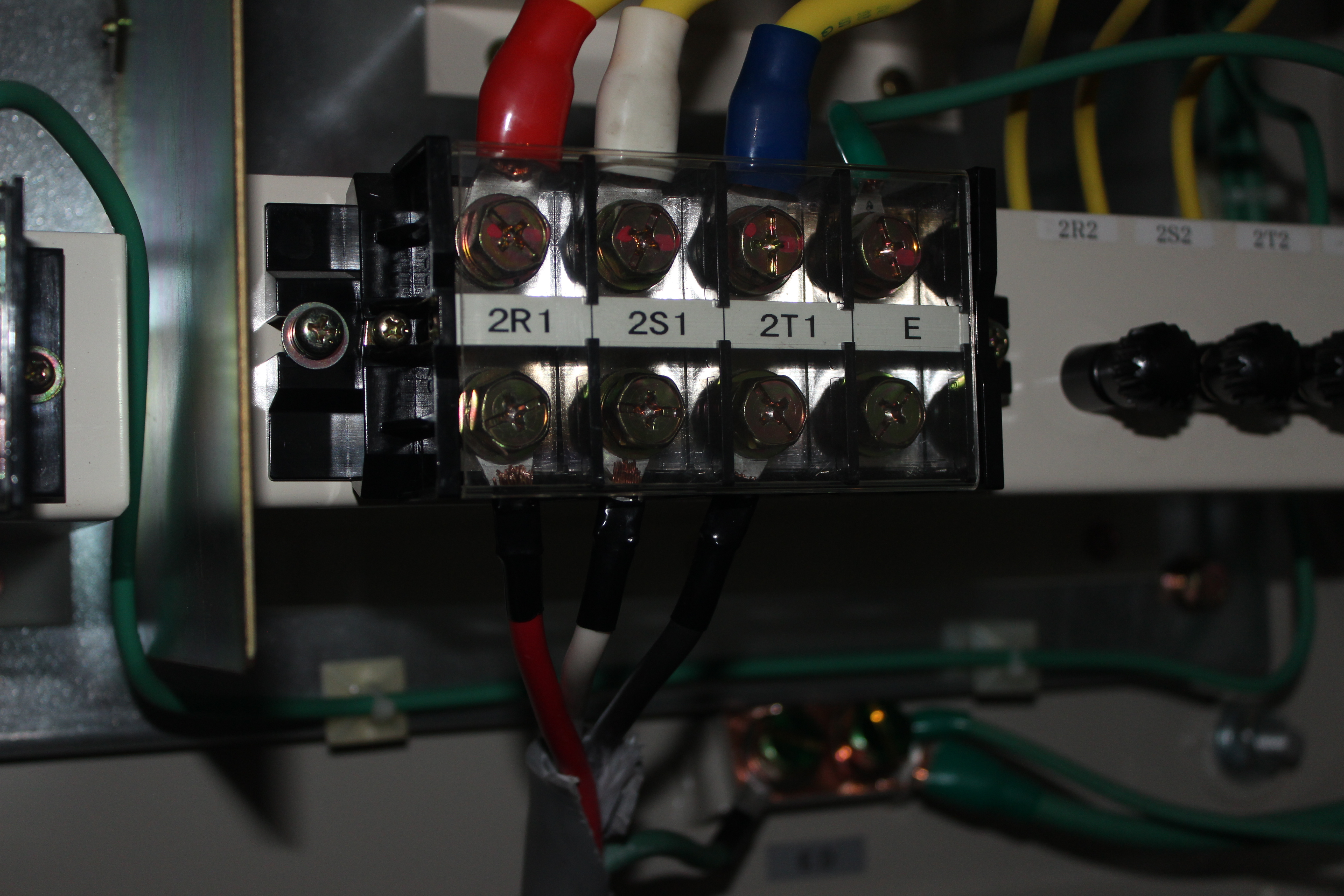
TD | AIDA adaptor PCB configuration - RIKEN - Feb 2015 |
|
| Attachment 1: IMG_2781.JPG
|
|
| Attachment 2: IMG_2782.JPG
|
|
| Attachment 3: IMG_2783.JPG
|
|
| Attachment 4: IMG_2784.JPG
|
|
| Attachment 5: IMG_2787.JPG
|
|
| Attachment 6: IMG_2796.JPG
|
|
|
64
|
Wed Apr 22 03:33:01 2015 |
TD | FEE64 Fast Discriminator OR o/p via MACB |
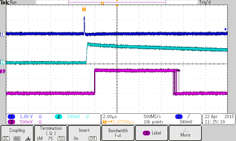
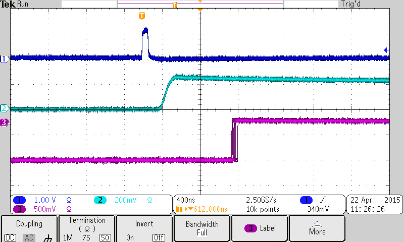
Illustration of the trigger timing of the AIDA FEE64 fast discriminator OR output via the
MACB front panel Trigger outputs.

Channel 1: BNC PB-4 Pulser Trigger Output
Channel 2: BNC PB-4 Pulser Analogue Output
Channel 3: MACB Trigger Output

MACB Trigger Output: NIM complement
                     width ~ 7us
                     delay ~ 750ns (with respect to BNC PB_4 Pulser Analogue Output)

Example illustrates MAC Trigger Output from nnaida5 with standard ASIC settings and
LEC/MEC fast discriminator 0x40 |
| Attachment 1: tek00000.tif
|
|
| Attachment 2: tek00001.tif
|
|
|
67
|
Thu Apr 23 03:21:48 2015 |
TD | MSL type BB18(DS)-1000 |
MSL type BB18

Serial			Thickness	Depletion	Date		Note			Location
			(um)		(V)

2933-7			1004		?		7.11.11		Mechanical Sample	Edinburgh

2933-13/2933-18/2933-20	1001/1001/990	290/300/340	24.11.11	Mechanical Sample	Edinburgh

2944-4                  1034                                                                    RIKEN
2944-10                 1038                                                                    RIKEN
2944-15			1044									Edinburgh

2977-6			1004		75		6.6.12		Pre-production series   RIKEN
	bond wire repair reqd
2977-7			1010		70		26.7.12		Pre-production series   RIKEN
2977-15			1007		75		26.7.12		Pre-production series   RIKEN
2977-20			1008		70		6.6.12		Pre-production series   RIKEN


2998-20			1006		100		21.3.13					Edinburgh
2998-22			1006									Edinburgh
2998-23			1012									Edinburgh

3058-2			1016		60		17.11.14				Edinburgh
3058-3			1033		70		10.11.14				Edinburgh
3058-4			1023		60		7.11.14					Edinburgh
3058-5			1010		70		23.2.15					Edinburgh
3058-6			1013		66		12.11.14				Edinburgh
3058-7			1027		63		10.11.14				Edinburgh
3058-9			1029		60		11.11.14				RIKEN
3058-25			1011		115		3.3.15					RIKEN

3131-9			925		120		16.2.15					RIKEN
3131-11 923 80 6.3.15 RIKEN |
|
80
|
Wed Apr 29 11:00:29 2015 |
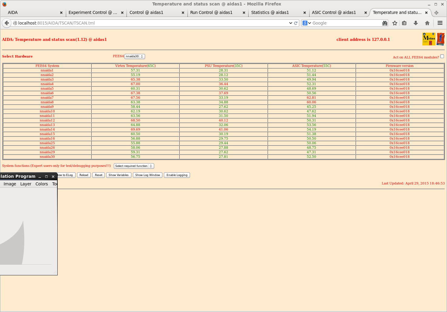
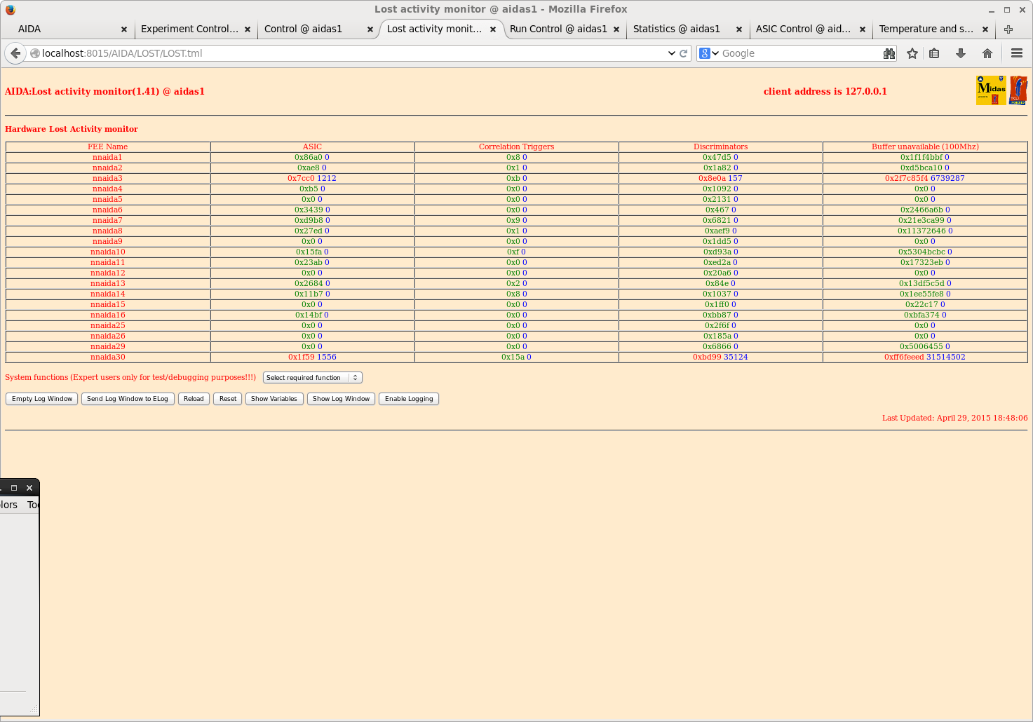
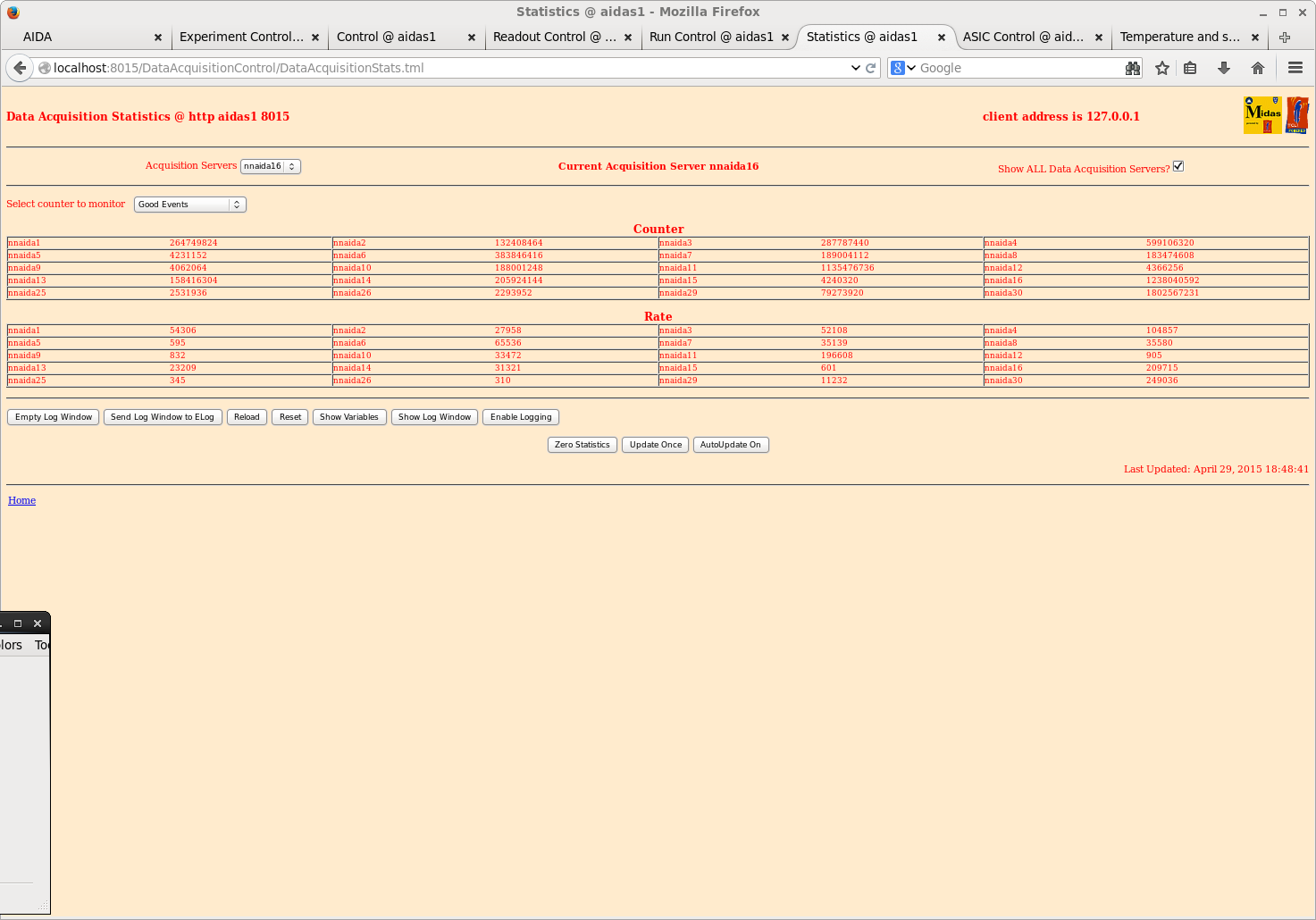
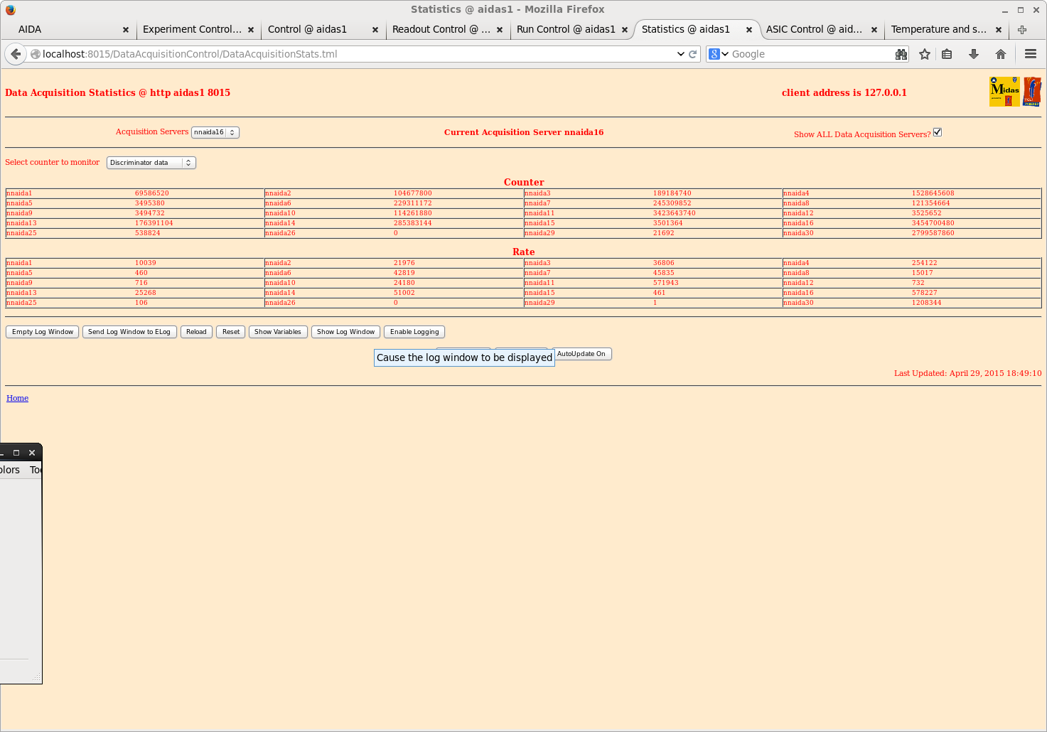
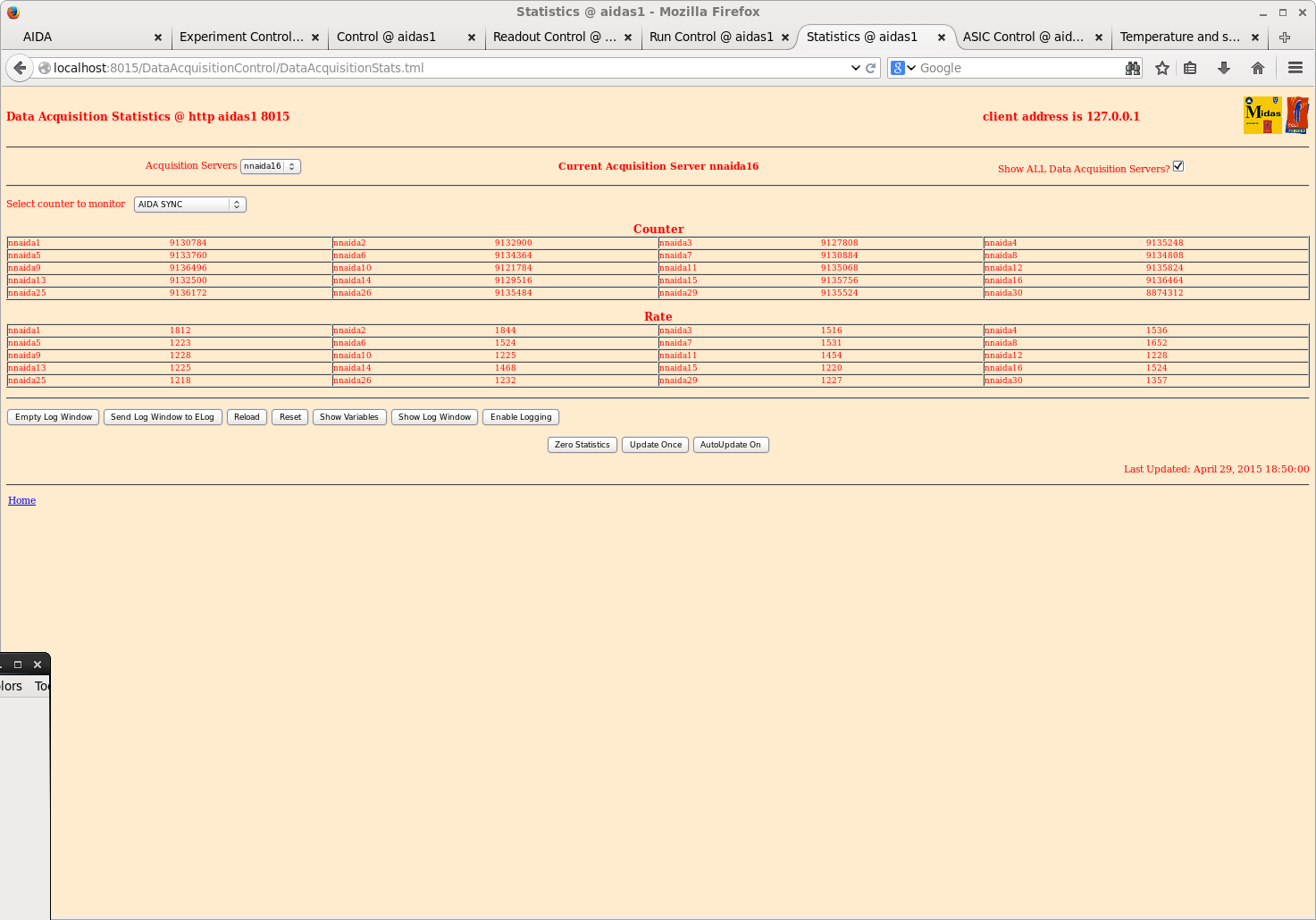
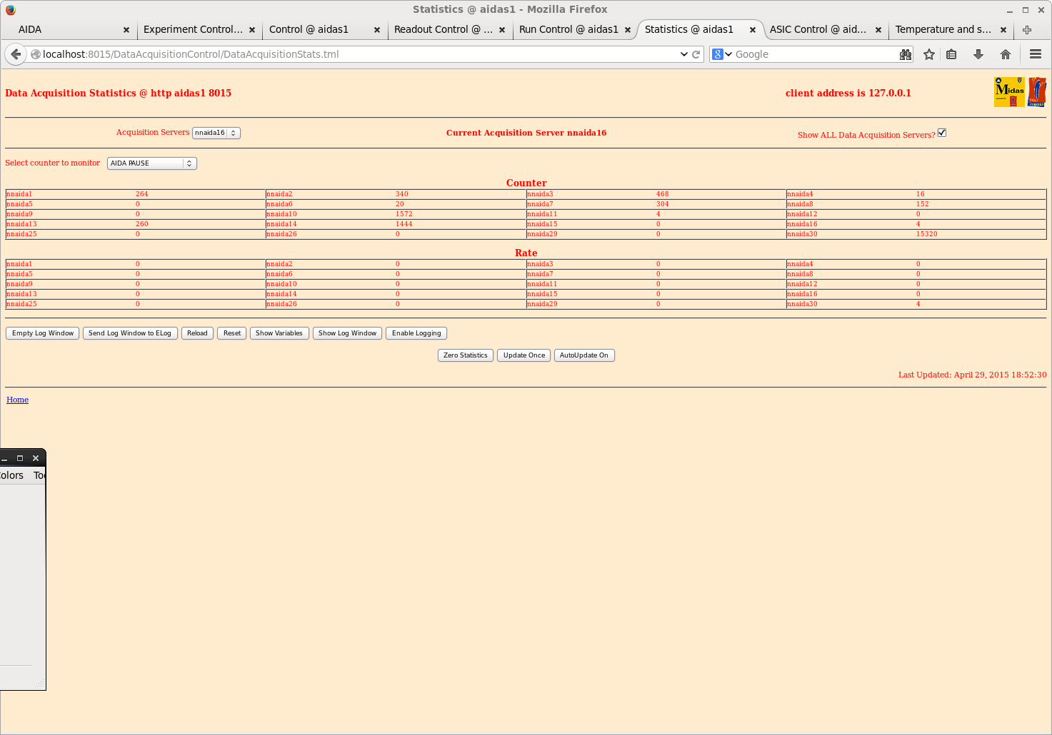
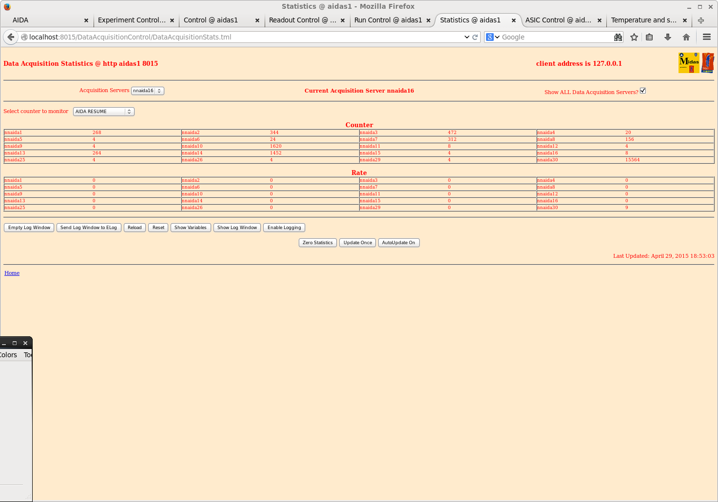
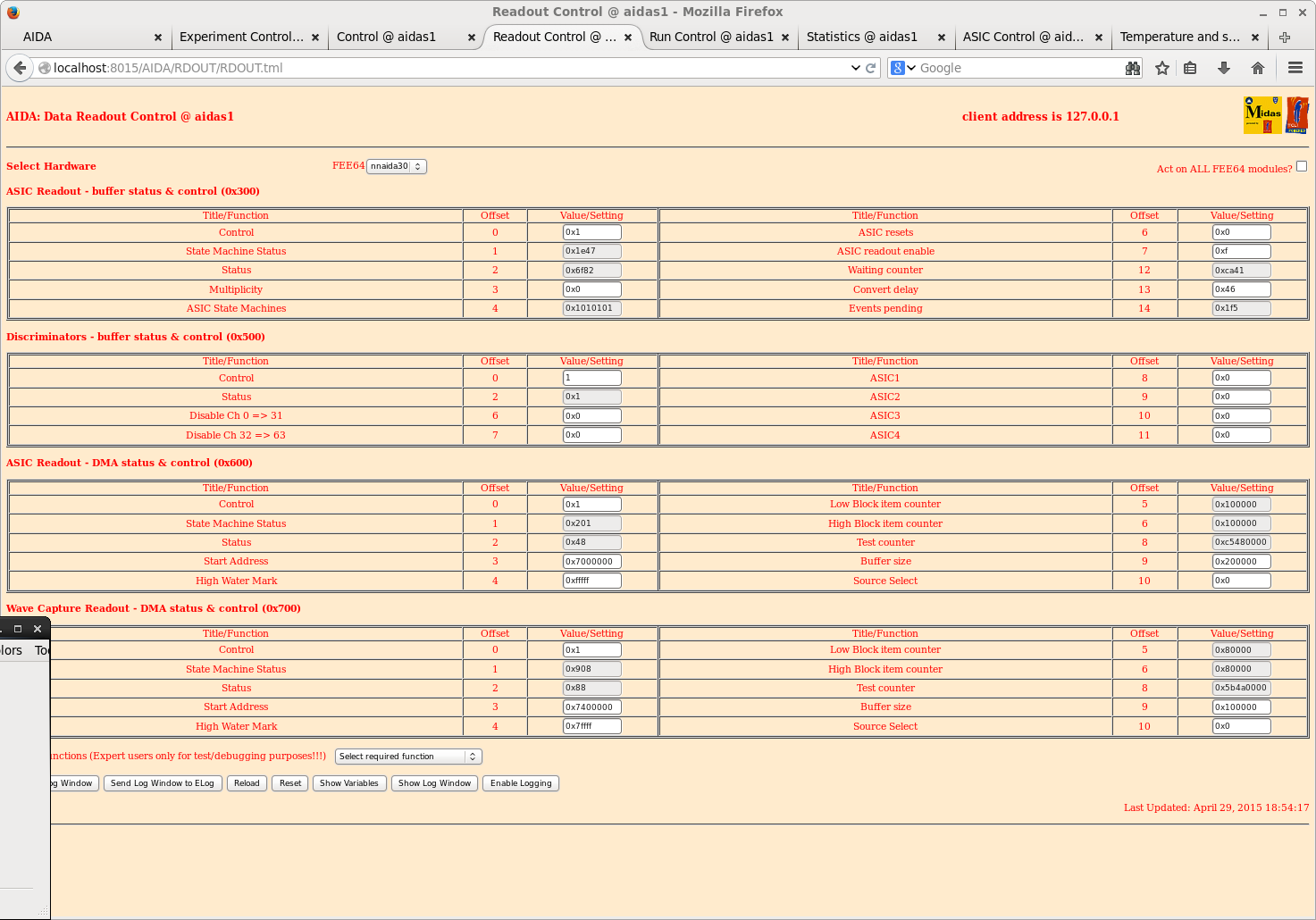
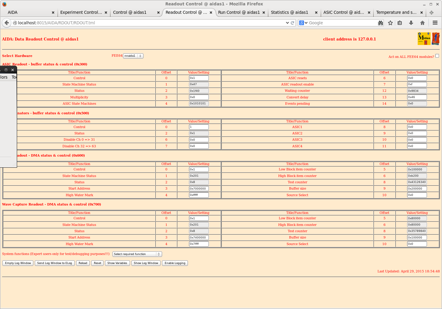
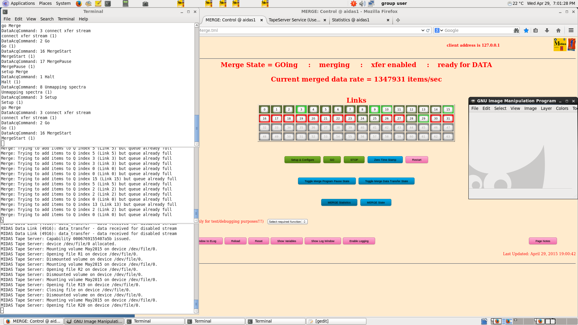
TD | Wednesday 29 April 2015 - R20 screenshots |
1230: Attachments

19.00 Screenshots taken during R20 |
| Attachment 1: 40.png
|
|
| Attachment 2: 41.png
|
|
| Attachment 3: 42.png
|
|
| Attachment 4: 43.png
|
|
| Attachment 5: 44.png
|
|
| Attachment 6: 45.png
|
|
| Attachment 7: 46.png
|
|
| Attachment 8: 47.png
|
|
| Attachment 9: 48.png
|
|
| Attachment 10: 49.png
|
|
|
84
|
Thu Apr 30 02:11:19 2015 |
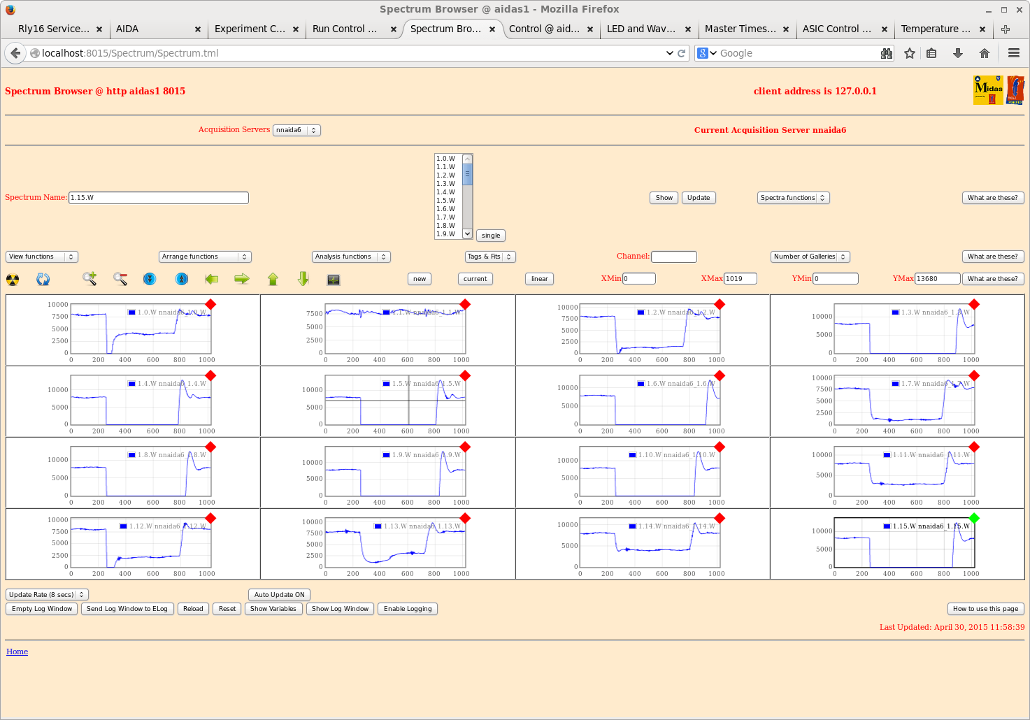
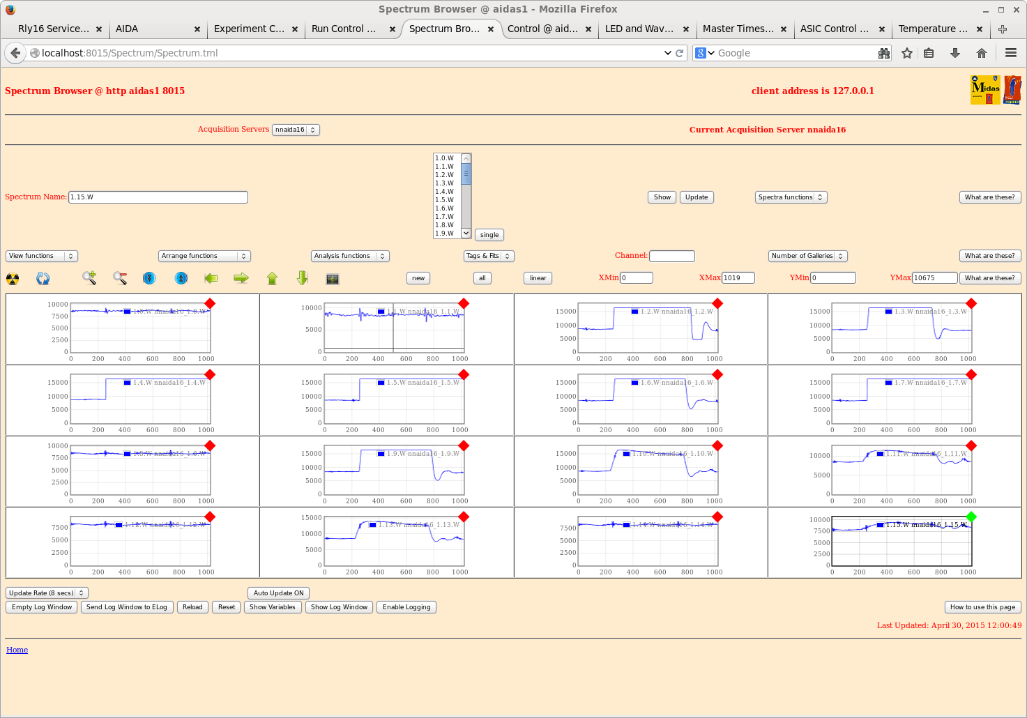
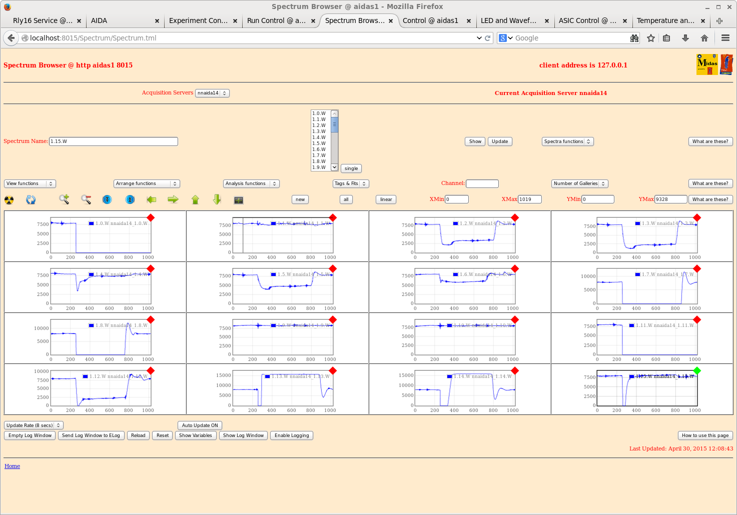
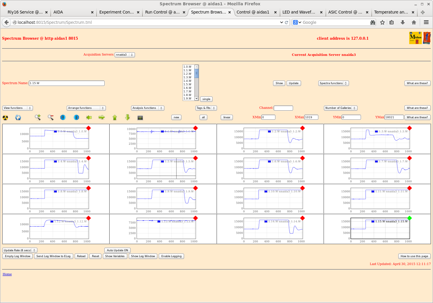
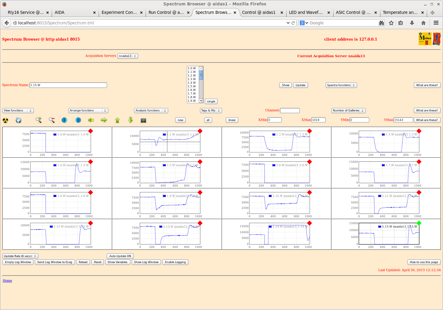
TD | Example waveforms with heavy-ion beam |
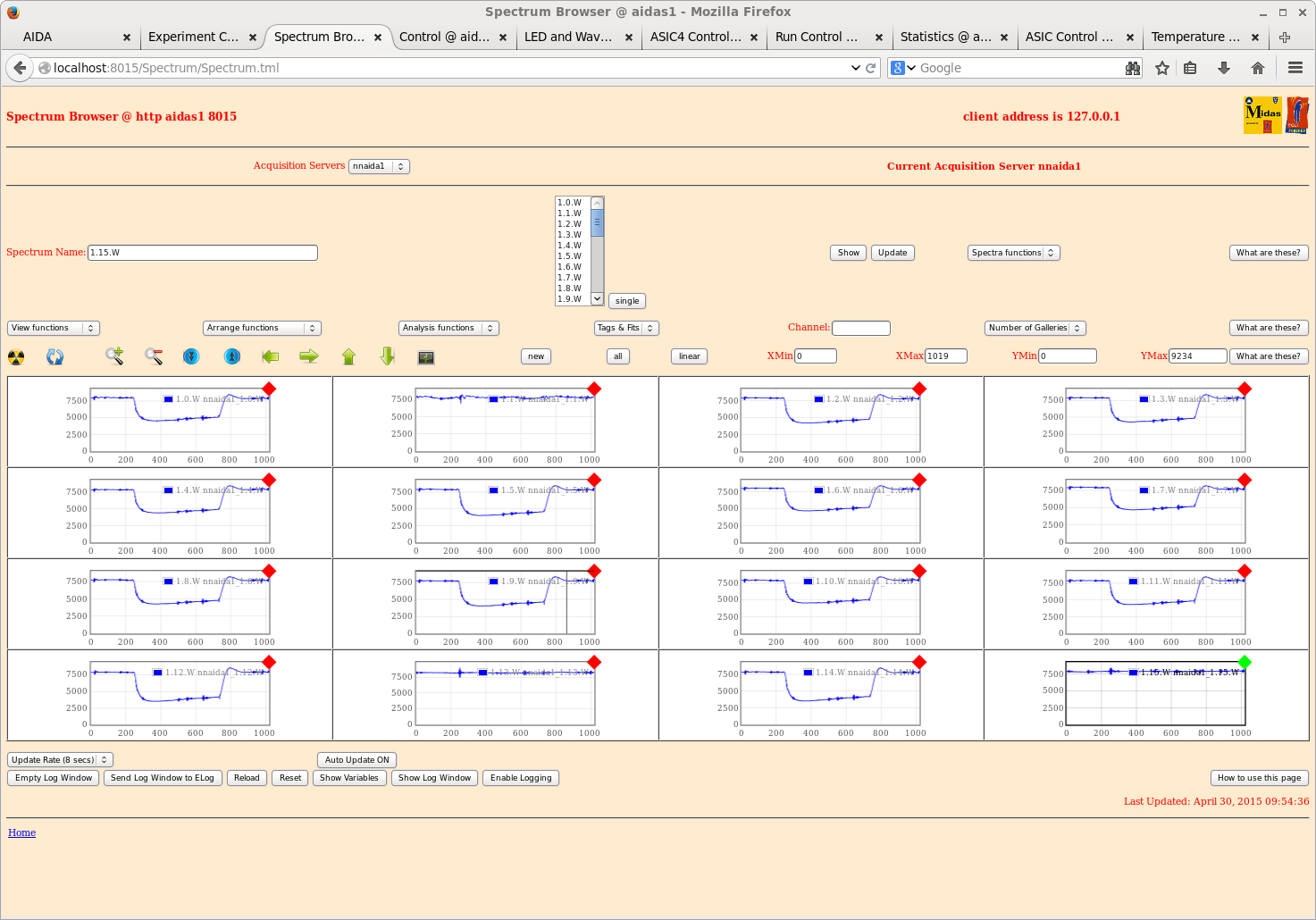
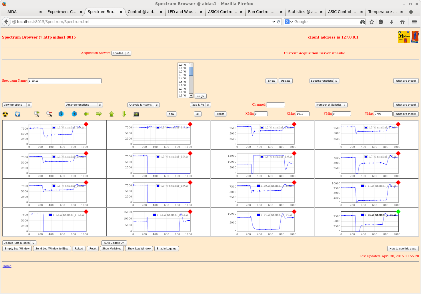
1 - nnaida1 DSSSD#3 p+n (pulser?)
2 - nnaida1 DSSSD#3 p+n heavy ion
3 - nnaida6 DSSSD#1 p+n
4 - nnaida16 DSSSD#1 n+n
5 - nnaida14 DSSSD#2 p+n
6 - nnaida3 DSSSD#3 n+n
7 - nnaida13 DSSSD#3 p+n

50MSPS, 14-bit ADC, 1000 samples
Each trace is the most recent capture for that specific channel |
| Attachment 1: 70.png
|
|
| Attachment 2: 71.png
|
|
| Attachment 3: 72.png
|
|
| Attachment 4: 73.png
|
|
| Attachment 5: 74.png
|
|
| Attachment 6: 75.png
|
|
| Attachment 7: 76.png
|
|