| |
ID |
Date |
Author |
Subject |
|
|
911
|
Mon Oct 23 10:52:06 2023 |
NH, CC | AIDA test |
Started AIDA at 11:50, writing to disk: file BG18OCT2/R3, stopped around 3 pm

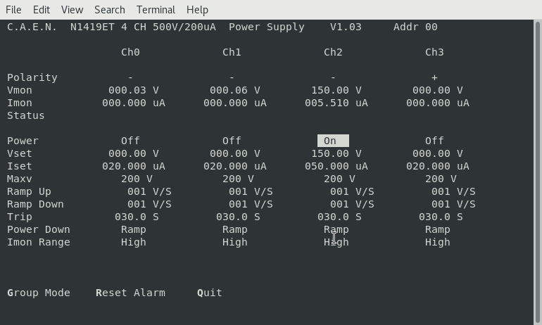
pict1: HV supply
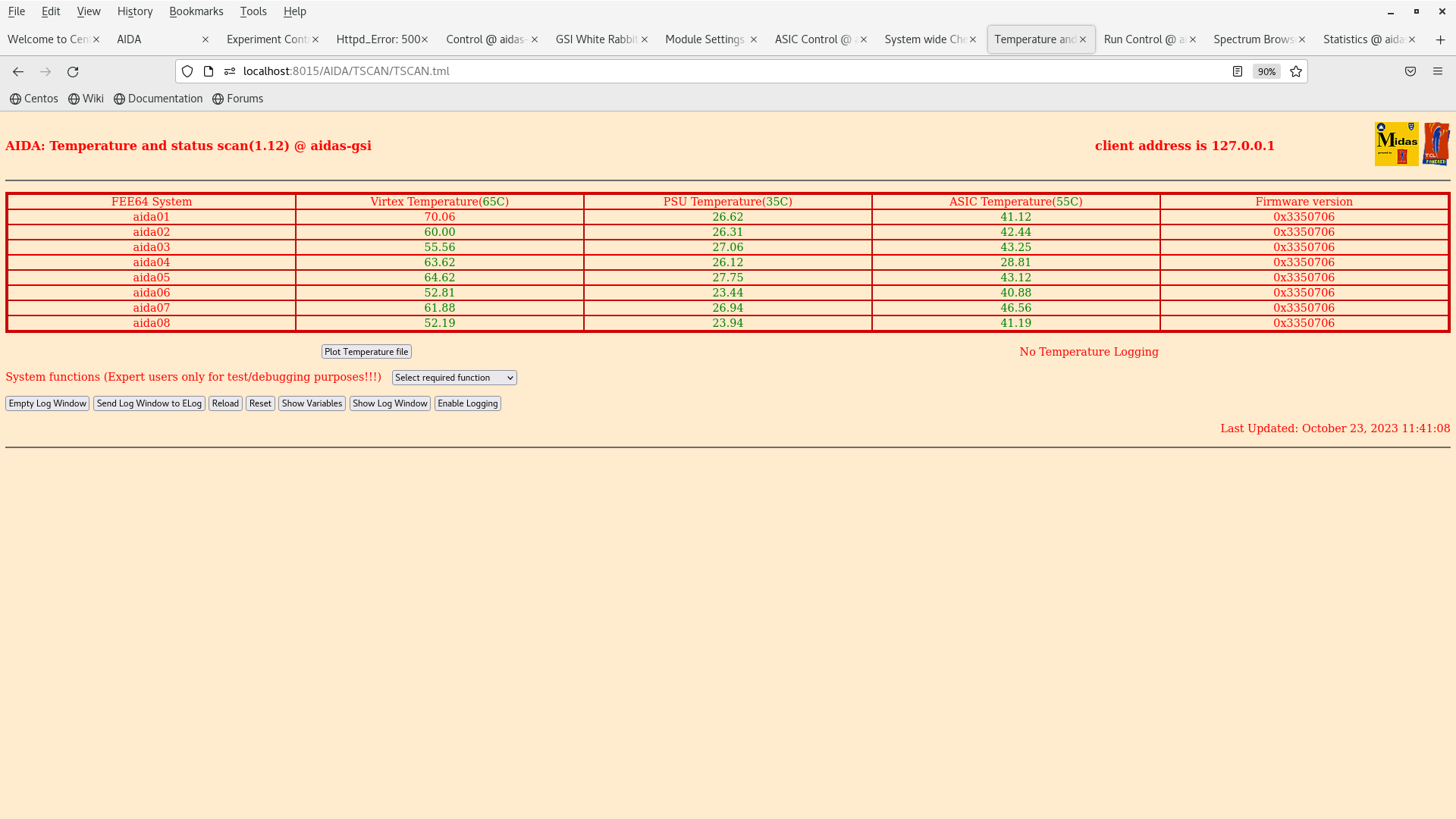
pict2: temperature
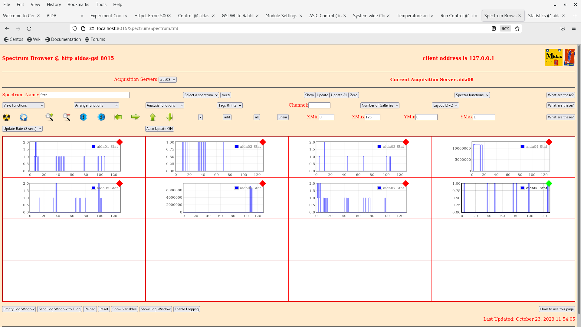
pict3: spectrum in stat, layout2
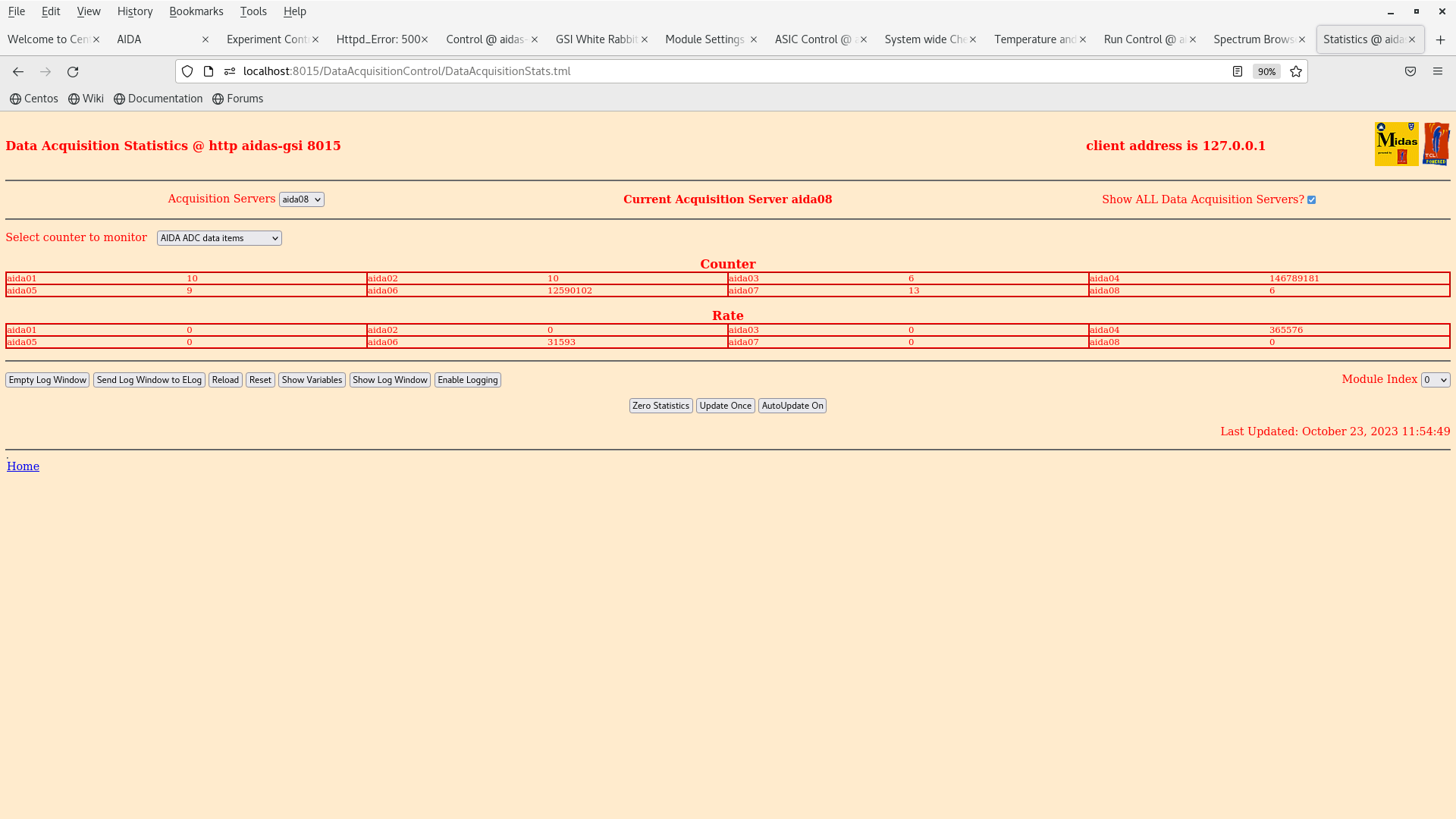
pict4: statistics |
| Attachment 1: Screenshot_from_2023-10-23_11-53-28.png
|
|
| Attachment 2: Screenshot_from_2023-10-23_11-53-59.png
|
|
| Attachment 3: Screenshot_from_2023-10-23_11-54-43.png
|
|
| Attachment 4: Screenshot_from_2023-10-23_11-54-54.png
|
|
|
|
912
|
Mon Oct 23 14:08:06 2023 |
NH, CC | AIDA test |
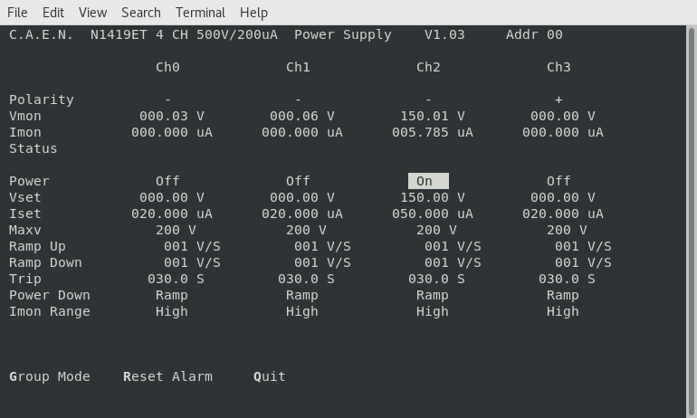
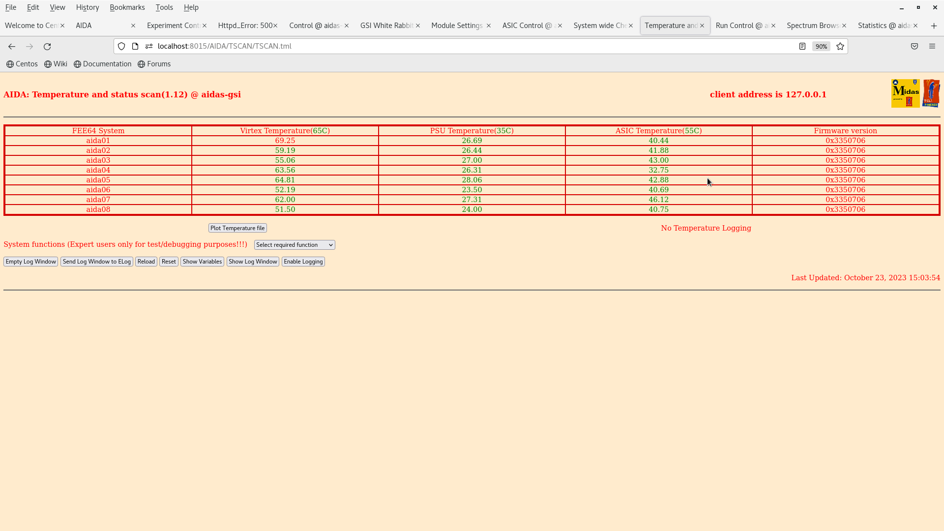
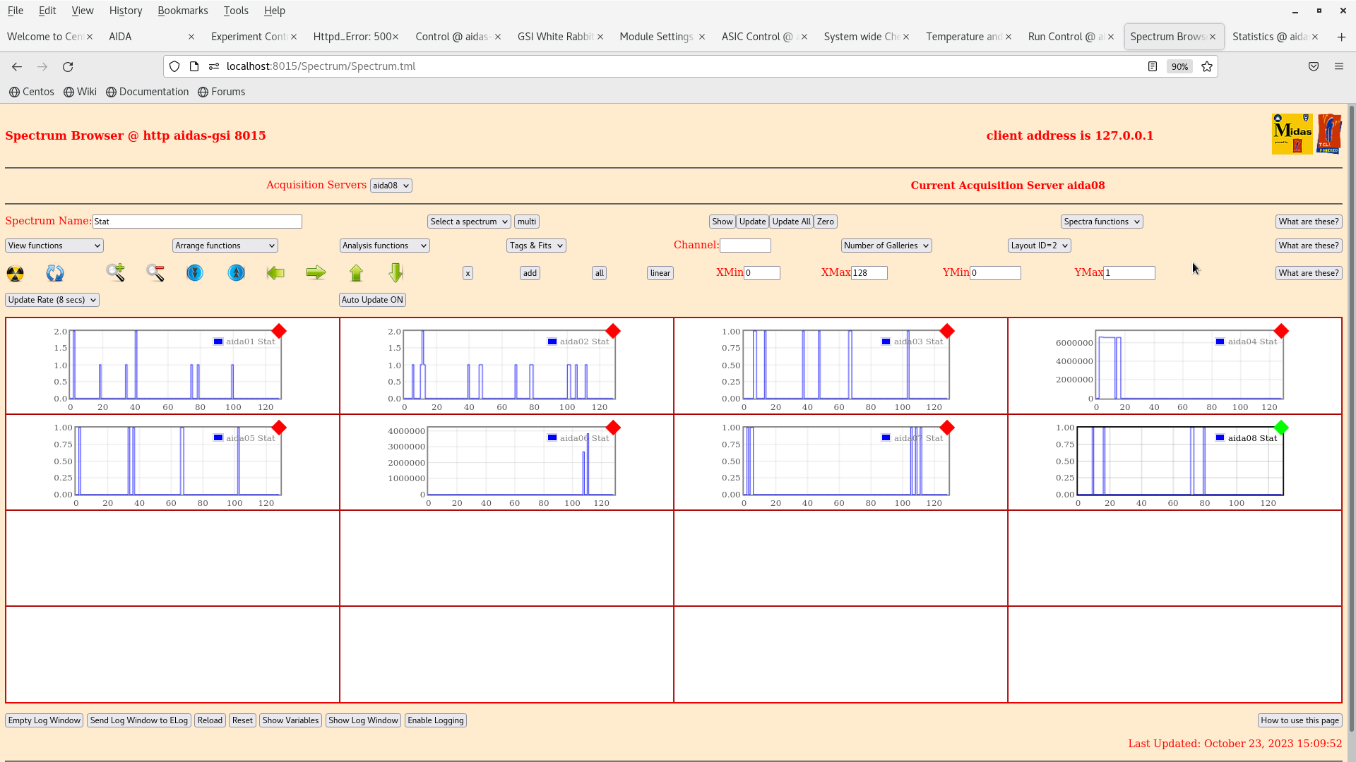
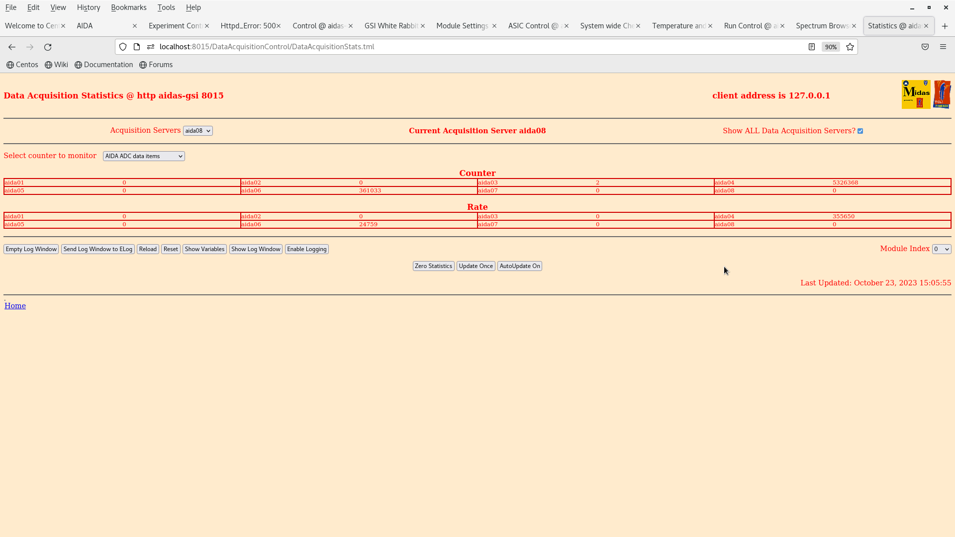
Started AIDA at 3:05pm, writing to disk: file BG18OCT2/R4, stopped 18.30

pict1: HV supply
pict2: temperature
pict3: spectrum in stat, layout2
pict4: statistics

pict5: sum spectra at 18:20 (3.4 hours)

system power off and unbiased |
| Attachment 1: Screenshot_from_2023-10-23_15-08-59.png
|
|
| Attachment 2: Screenshot_from_2023-10-23_15-09-16.png
|
|
| Attachment 3: Screenshot_from_2023-10-23_15-10-01.png
|
|
| Attachment 4: Screenshot_from_2023-10-23_15-09-36.png
|
|
| Attachment 5: Screenshot_from_2023-10-23_18-20-13.png
|
|
|
|
913
|
Tue Oct 24 10:54:14 2023 |
at 19:14NH, CC | AIDA test |
Started AIDA at 11:54am, writing to disk: file BG18OCT2/R5, stopped at 19:14

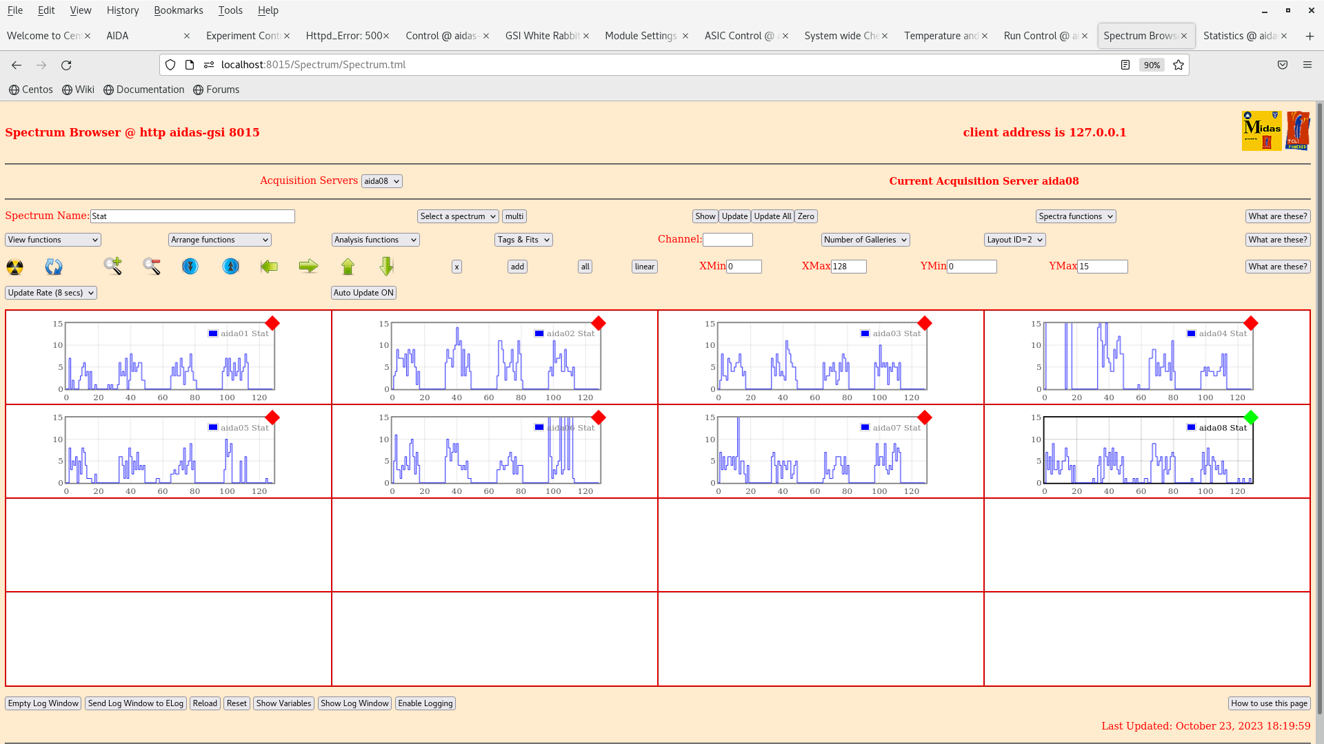
pict1: HV supply
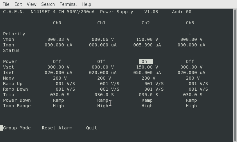
pict2: temperature
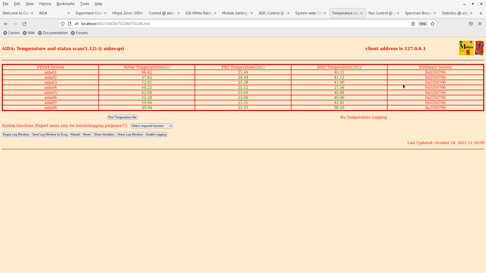
pict3: spectrum in stat, layout2
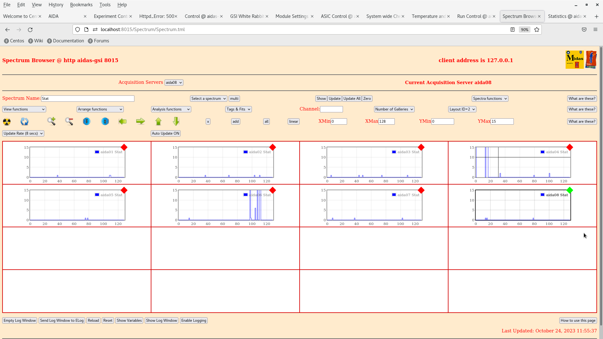
pict4: statistics

pict5: sum spectra at 18:20 (3.4 hours)

system power off and unbiased |
| Attachment 1: Screenshot_from_2023-10-24_11-54-48.png
|
|
| Attachment 2: Screenshot_from_2023-10-24_11-55-08.png
|
|
| Attachment 3: Screenshot_from_2023-10-24_11-55-46.png
|
|
| Attachment 4: Screenshot_from_2023-10-24_11-55-33.png
|
|
|
|
914
|
Wed Oct 25 12:42:18 2023 |
CC | AIDA test |
Started AIDA at 1:41 pm, writing to disk: file BG18OCT2/R6, stopped at  17:26
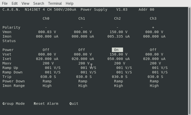
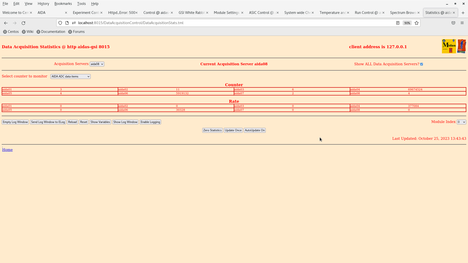
pict1: HV supply
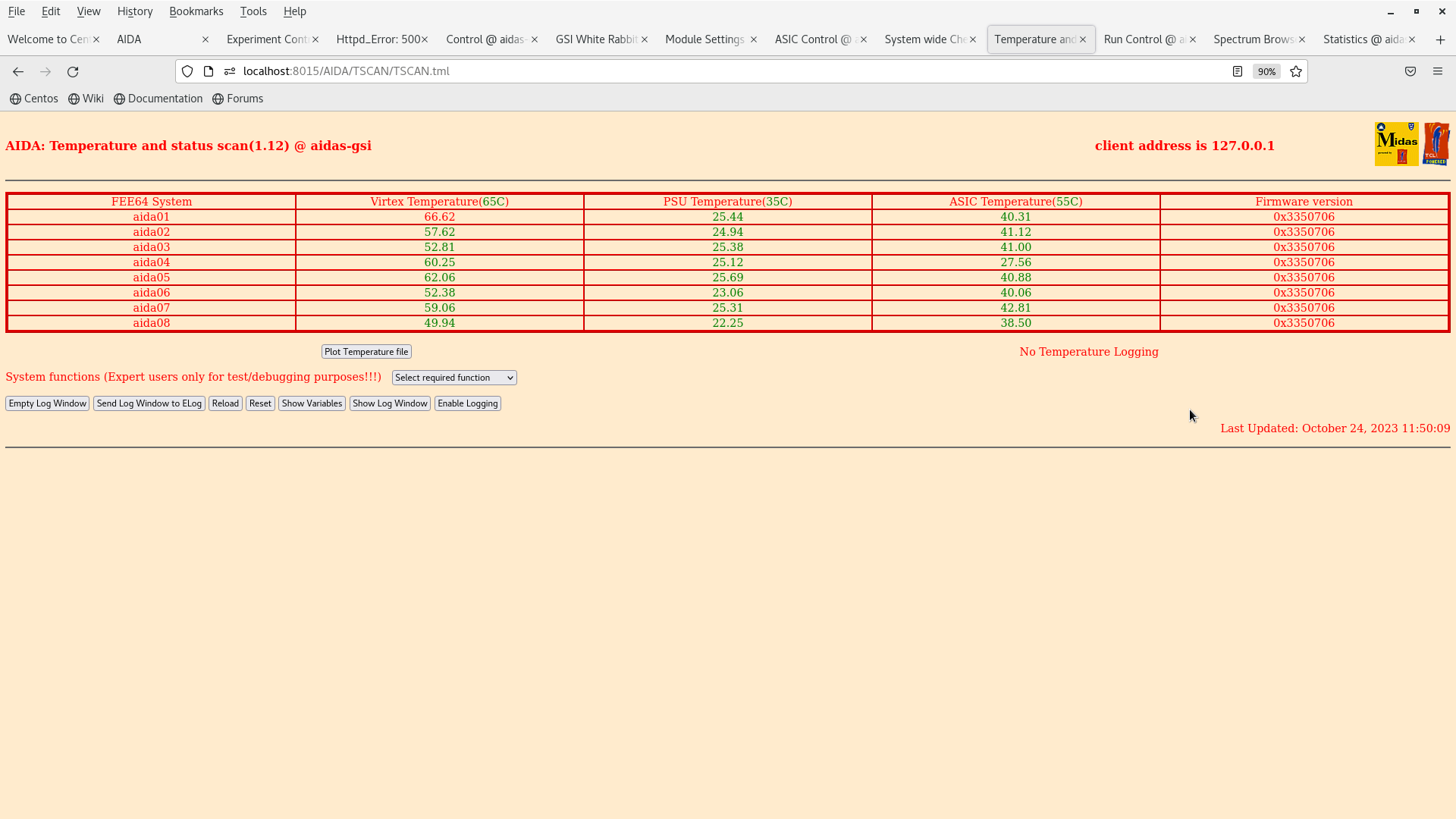
pict2: temperature
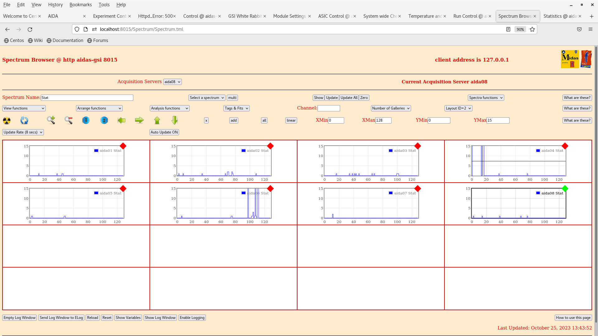
pict3: spectrum in stat, layout2
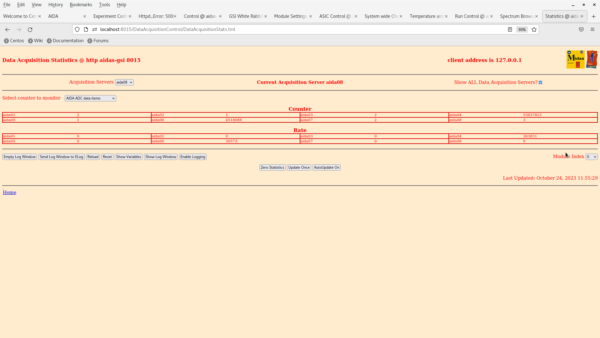
pict4: statistics |
| Attachment 1: Screenshot_from_2023-10-25_13-42-54.png
|
|
| Attachment 2: Screenshot_from_2023-10-25_13-43-10.png
|
|
| Attachment 3: Screenshot_from_2023-10-25_13-44-00.png
|
|
| Attachment 4: Screenshot_from_2023-10-25_13-43-46.png
|
|
|
|
858
|
Thu Jun 20 07:42:54 2019 |
CA, TD | AIDA shutdown checklist |
stop the daq

pause merger

stop TapeServer

housekeeping checks

bias off

individually turn power relays off

switch off 2x NIN bins, 1x fan tray

do not turn off clock!!

turn off aida circuits at power box (careful!)

turn chiller off - press and hold arrow button

front panel switch on chiller - off

wall 3 phase power - off

withdraw aida clear from DTAS - slowly!

return power tool, temperature probe and water container to corral

*if cables*

network cables - blue, disconnect at switch, reel up at stairwell

disconnect clock

aida plastic high voltage and signal

cables from root macb trigger and reset to DTAS

mains cables from mains box

then move aida! |
|
|
280
|
Mon Jun 6 08:57:34 2016 |
GL,PW, YS, TD, ML | AIDA run 1112 - Sync problem |
After starting run 1112, we noticed that the merge program was waiting for a first sync. It then turned out that all syncs had disappeared. This required an entire reboot of the AIDA DAQ. Consequently, AIDA run 1112 should not be used. |
|
|
323
|
Tue Jul 5 10:26:11 2016 |
DK | AIDA relocation pictures |
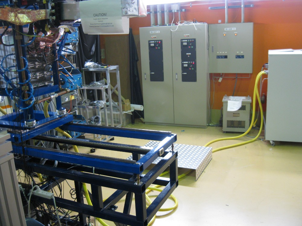
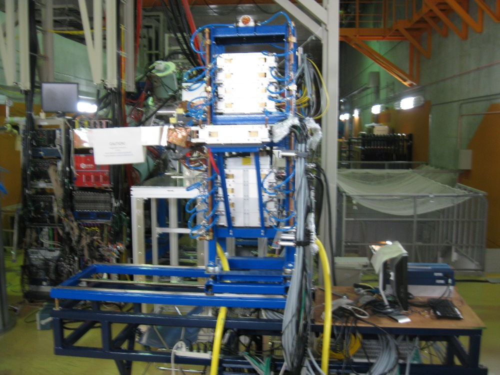
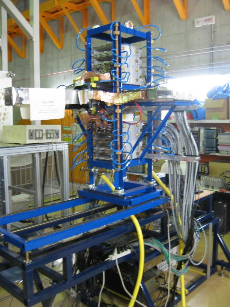
Here are some pictures after AIDA's relocation.
In principle, it can stay here, but probably after the tests we will push it further against the wall. However, power and ethernet cabling cannot reach that far.
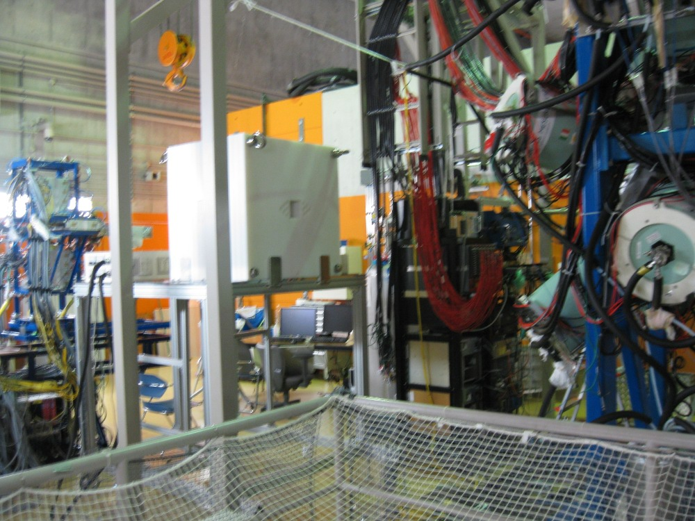
Attachment 1: Shows EURICA (original position) B-RIKEN moderator (near old AIDA spot) and AIDA (pushed downstream, rotated 90 degrees counterclockwise)
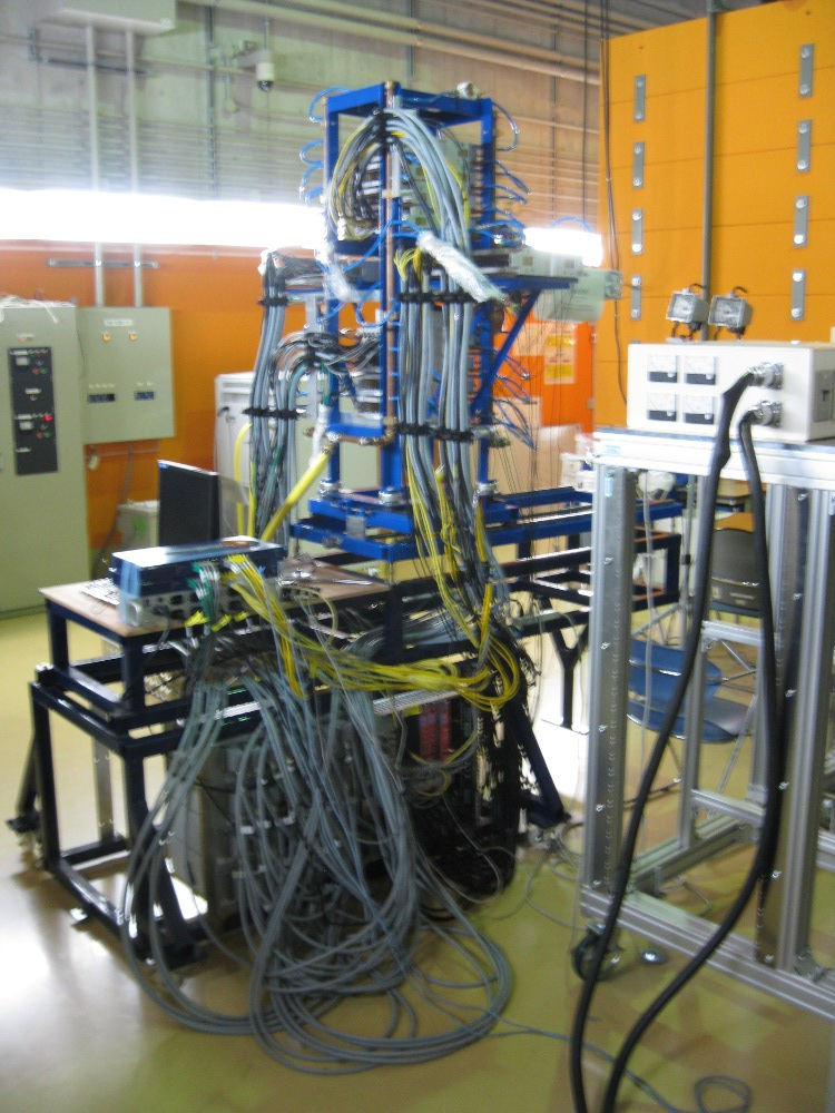
Attachment 2: Zoom in on AIDA from above. Nominally the beam left downstream perspective. Power supply is also seen on BRIKEN moderator table.
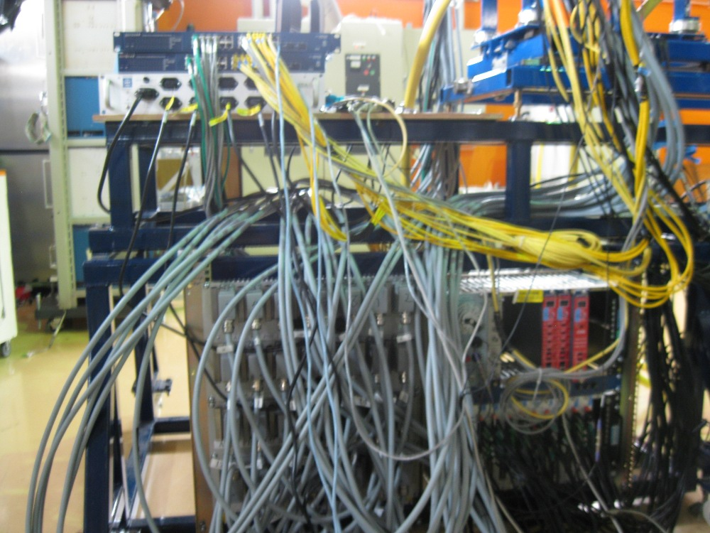
Attachment 3: Zoom in further of above, namely near FEE power supply rack
Attachment 4: More upstream view, still on beam left, showing tube with SSDs as well as water cooler in background
Attachment 5: Beam right view
Attachment 6: Beam right view from more upstream perspective, also showing the full tower of electronics. |
| Attachment 1: eurica-briken-aida.jpg
|
|
| Attachment 2: beam-left-downstream.jpg
|
|
| Attachment 3: fee64-power.jpg
|
|
| Attachment 4: beam-left-cooler.JPG
|
|
| Attachment 5: beam-right.JPG
|
|
| Attachment 6: beam-right-tower.jpg
|
|
|
|
815
|
Mon May 27 08:29:02 2019 |
TD | AIDA position within DTAS |
AA informs me that the *centre* of the DTAS detector system is 26.7cm downstream
of the upstream edge of the upstream DTAS NaI(Tl) detectors.

The 6x DSSSDs are currently positioned per the 8x DSSSD setup of June 2018, i.e.
the 6x DSSSDs are in positions 3-8 (as indicated on the AIDA snout).

Detectors #4 & #5 are centred ~9cm from upstream edge of AIDA snout.

This means that the upstream edge of the AIDA snout should be 26.7-9=17.7cm
from the upstream edge of the upstream DTAS NaI(Tl) detectors. |
|
|
320
|
Thu Jun 16 08:18:50 2016 |
TD | AIDA photographs - May 2016 |
|
| Attachment 1: IMG_5751.JPG
|
|
| Attachment 2: IMG_5721.JPG
|
|
|
|
321
|
Sat Jun 18 14:35:31 2016 |
TD | AIDA photographs - June 2016 - 4 |
|
| Attachment 1: IMG_5854.JPG
|
|
| Attachment 2: IMG_5855.JPG
|
|
| Attachment 3: IMG_5856.JPG
|
|
| Attachment 4: IMG_5857.JPG
|
|
| Attachment 5: IMG_5863.JPG
|
|
|
|
319
|
Thu Jun 16 08:12:51 2016 |
TD | AIDA photographs - June 2016 - 3 |
|
| Attachment 1: IMG_5849.JPG
|
|
| Attachment 2: IMG_5850.JPG
|
|
| Attachment 3: IMG_5851.JPG
|
|
|
|
318
|
Thu Jun 16 08:07:37 2016 |
TD | AIDA photographs - June 2016 - 2 |
|
| Attachment 1: IMG_5842.JPG
|
|
| Attachment 2: IMG_5843.JPG
|
|
| Attachment 3: IMG_5846.JPG
|
|
| Attachment 4: IMG_5847.JPG
|
|
|
|
317
|
Thu Jun 16 08:00:10 2016 |
TD | AIDA photographs - June 2016 - 1 |
|
| Attachment 1: IMG_5838.JPG
|
|
| Attachment 2: IMG_5839.JPG
|
|
| Attachment 3: IMG_5840.JPG
|
|
| Attachment 4: IMG_5841.JPG
|
|
|
|
274
|
Sat Jun 4 08:46:20 2016 |
TD | AIDA noise - state of play 2 |
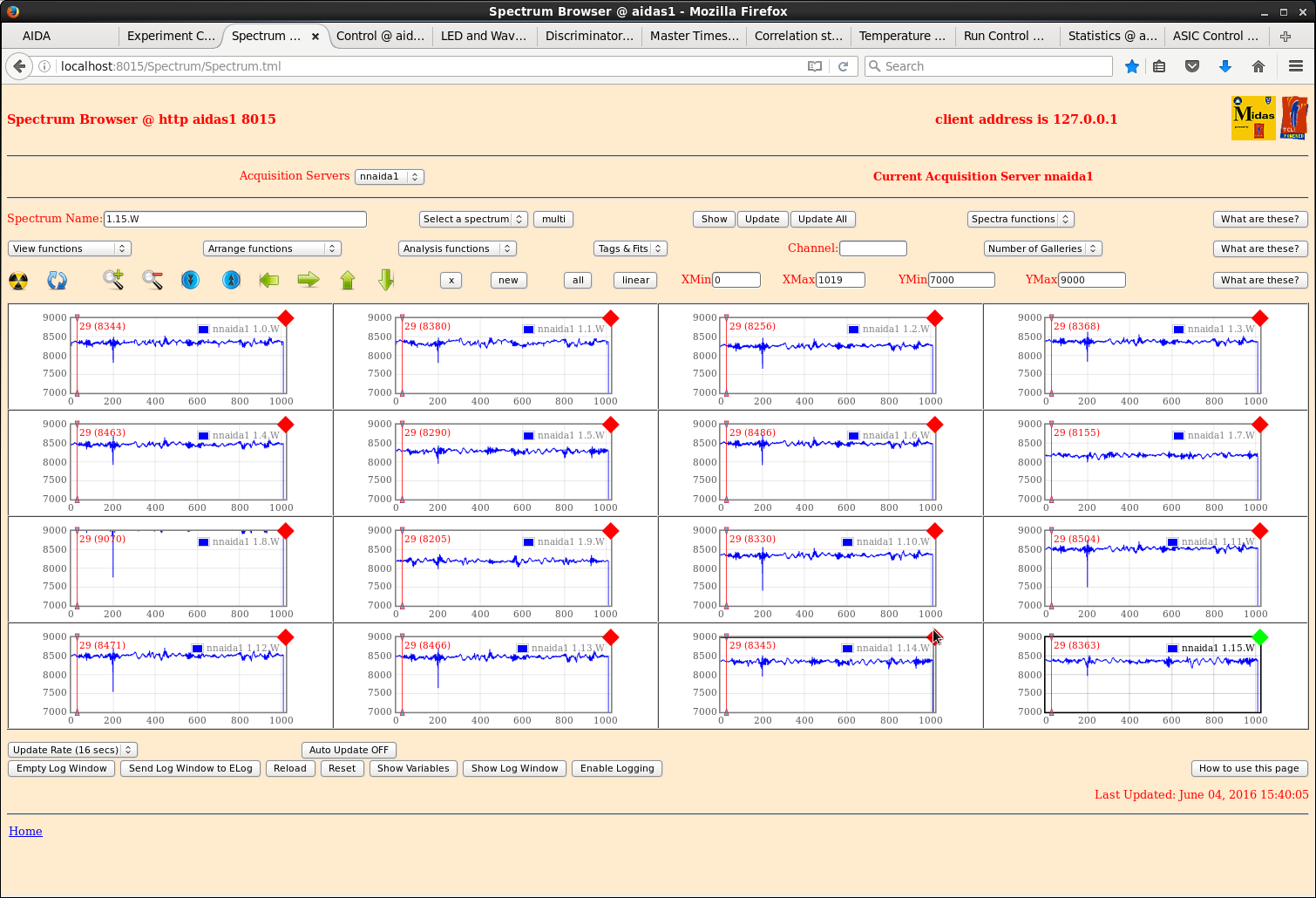
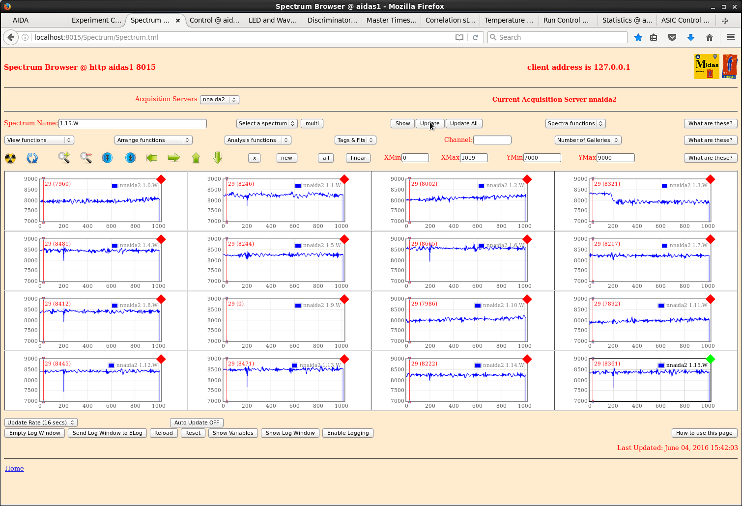
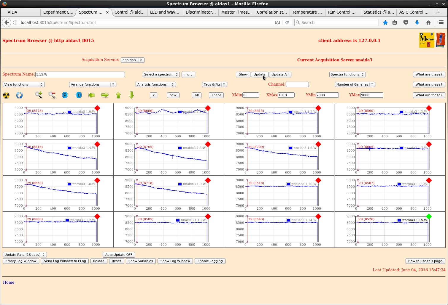
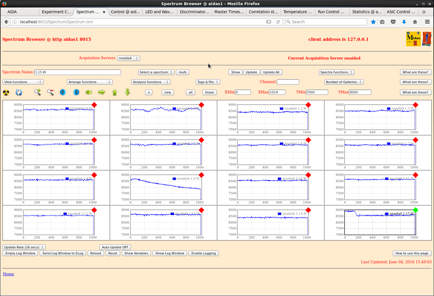
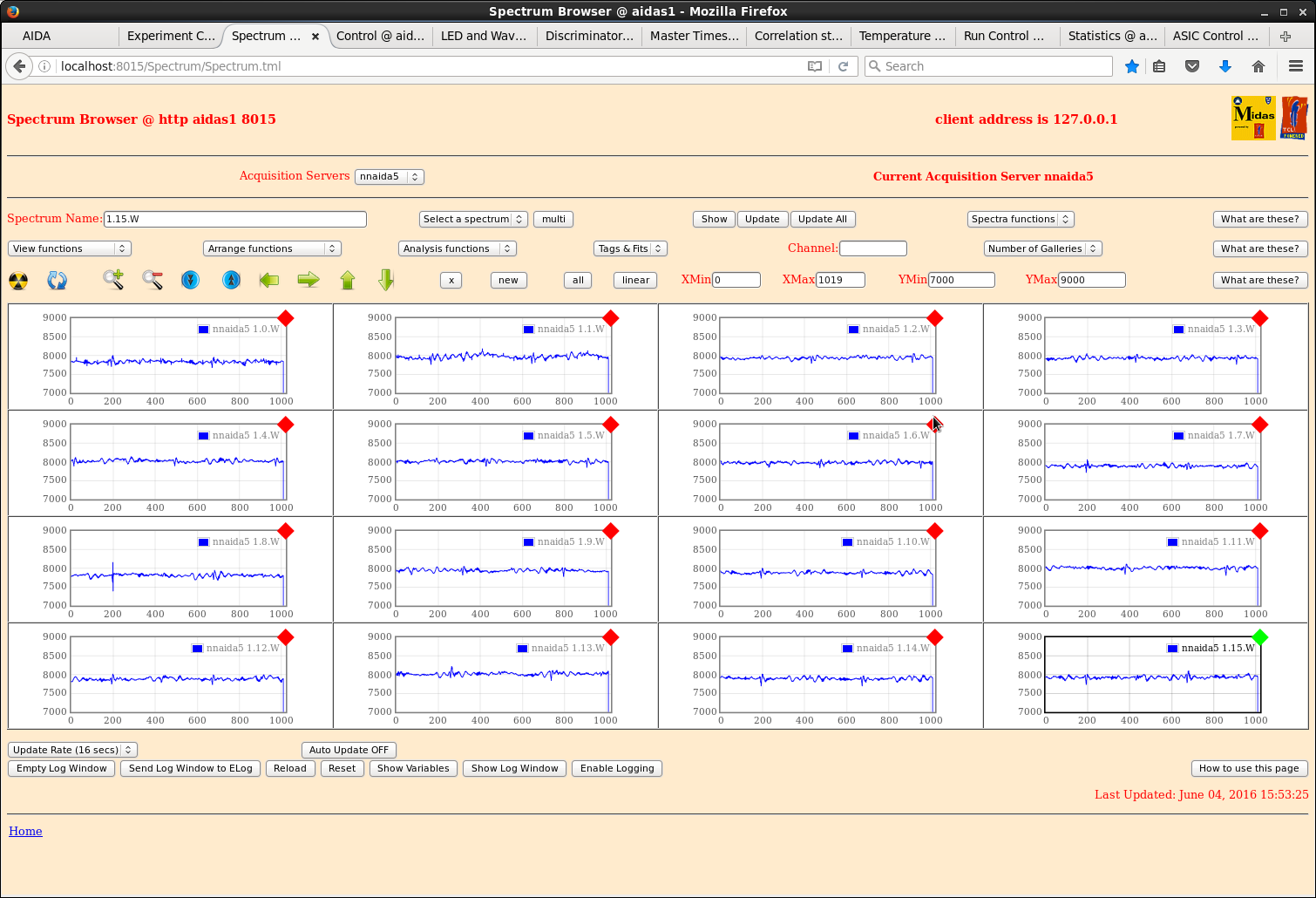
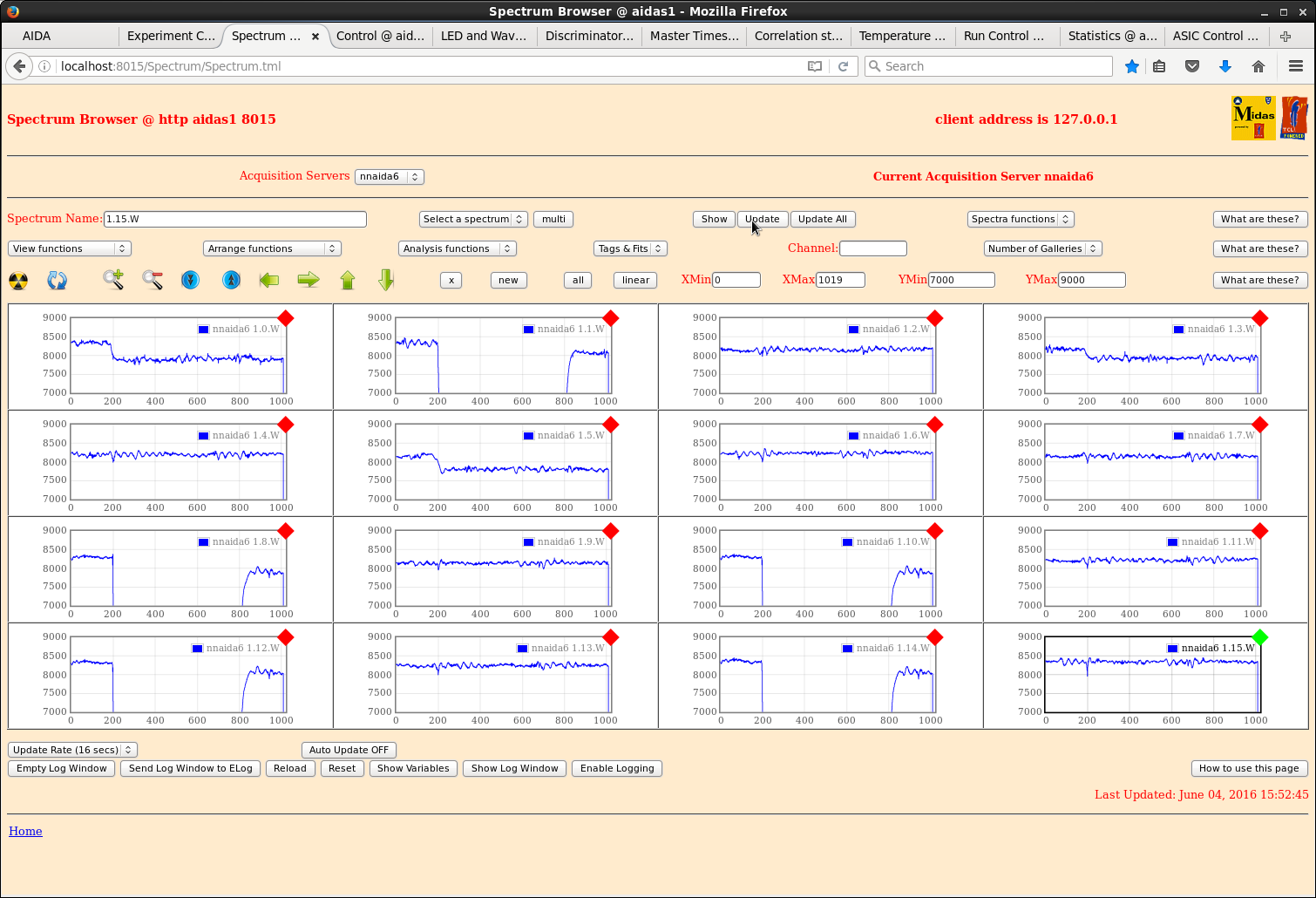
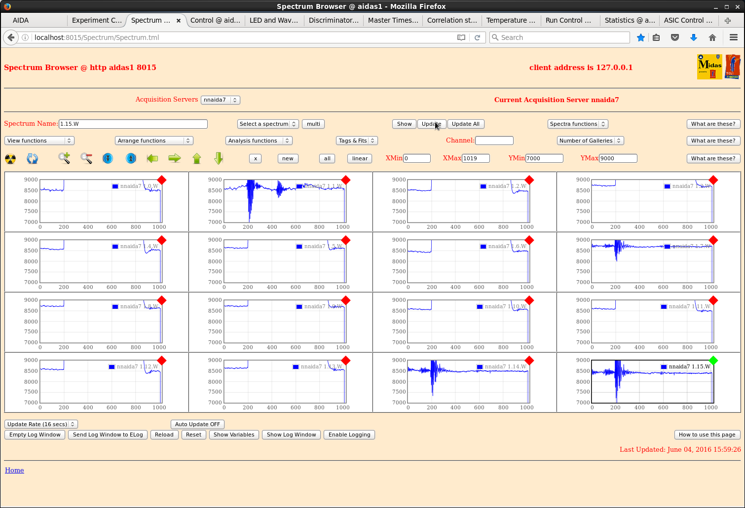
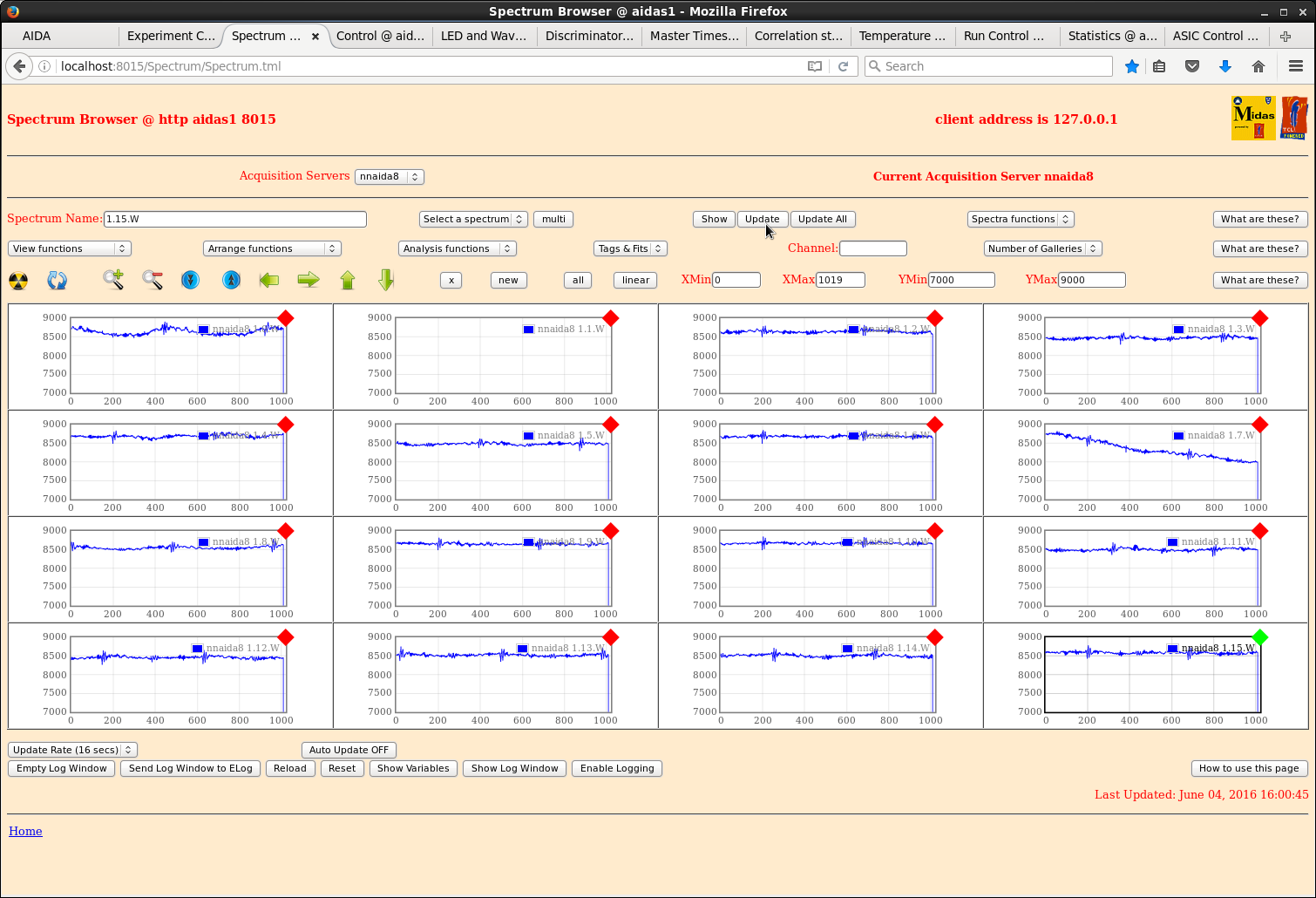
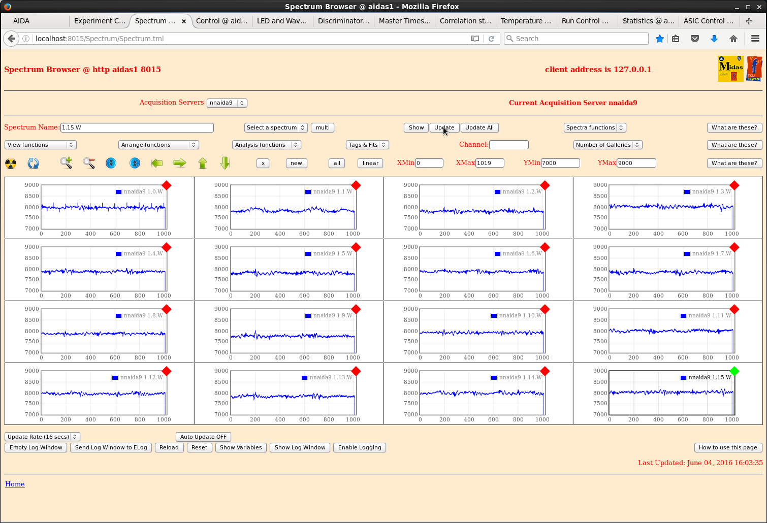
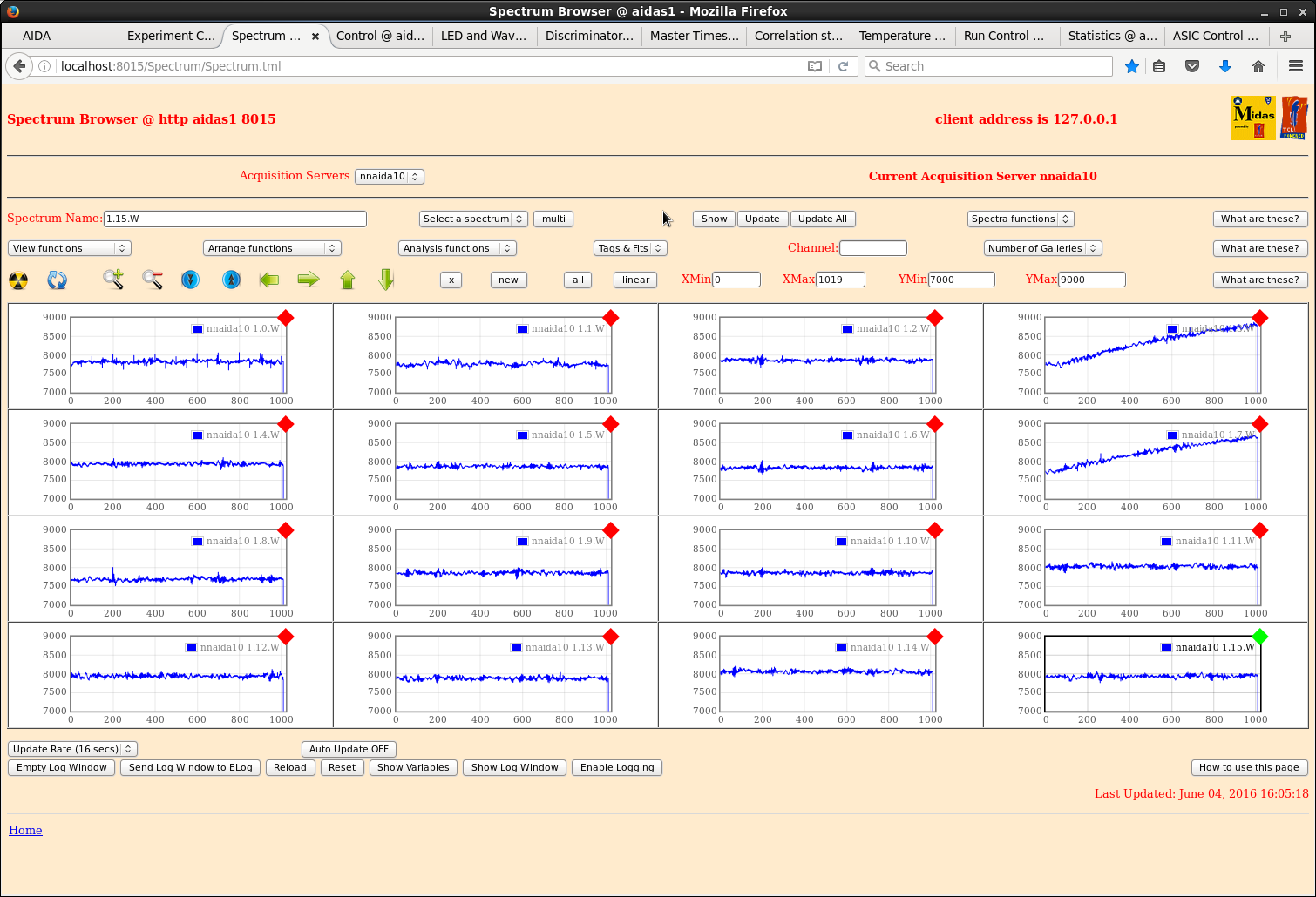
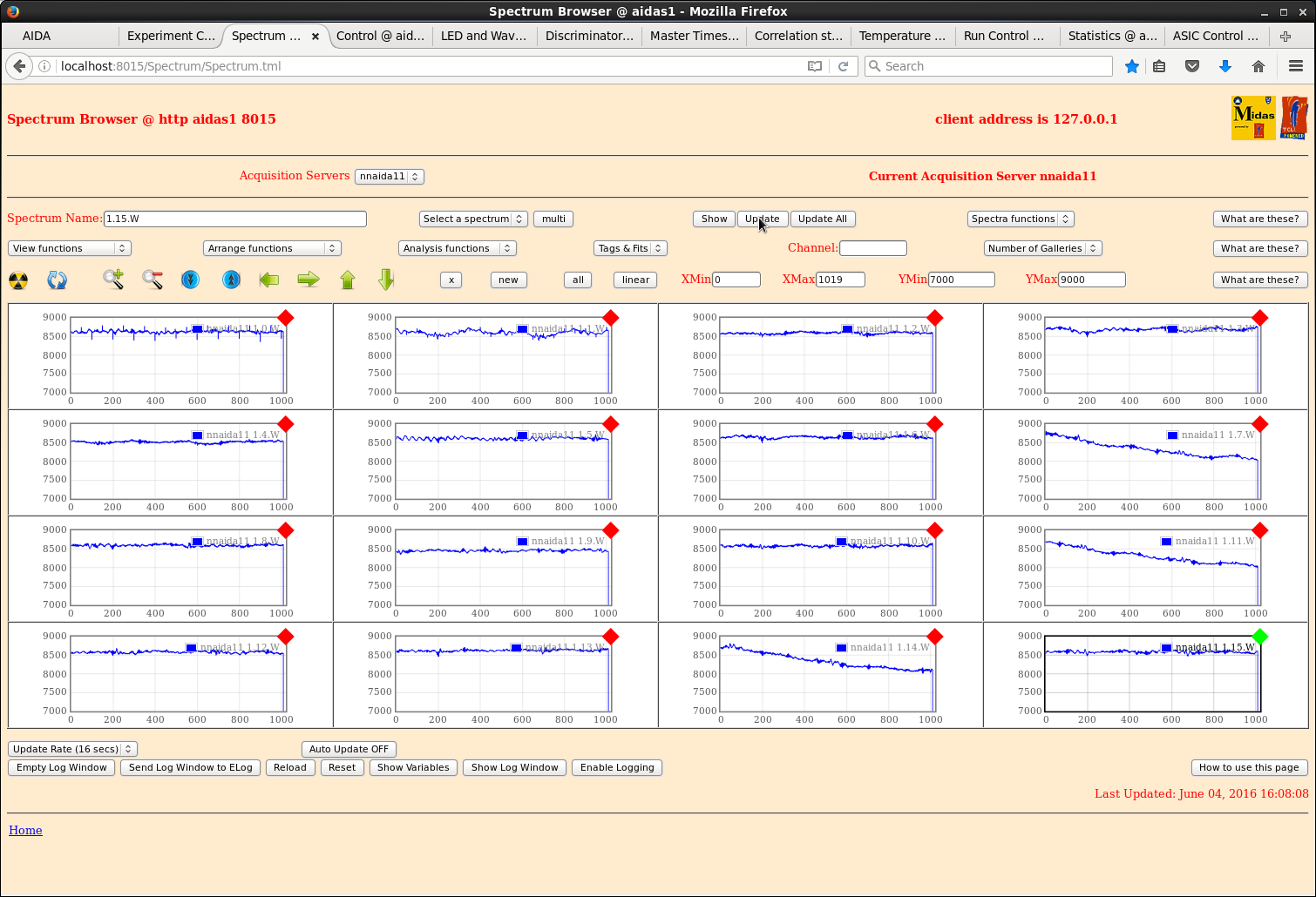
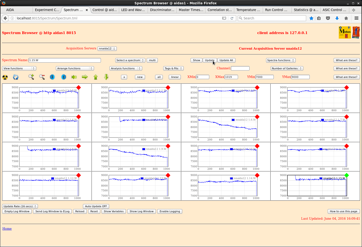
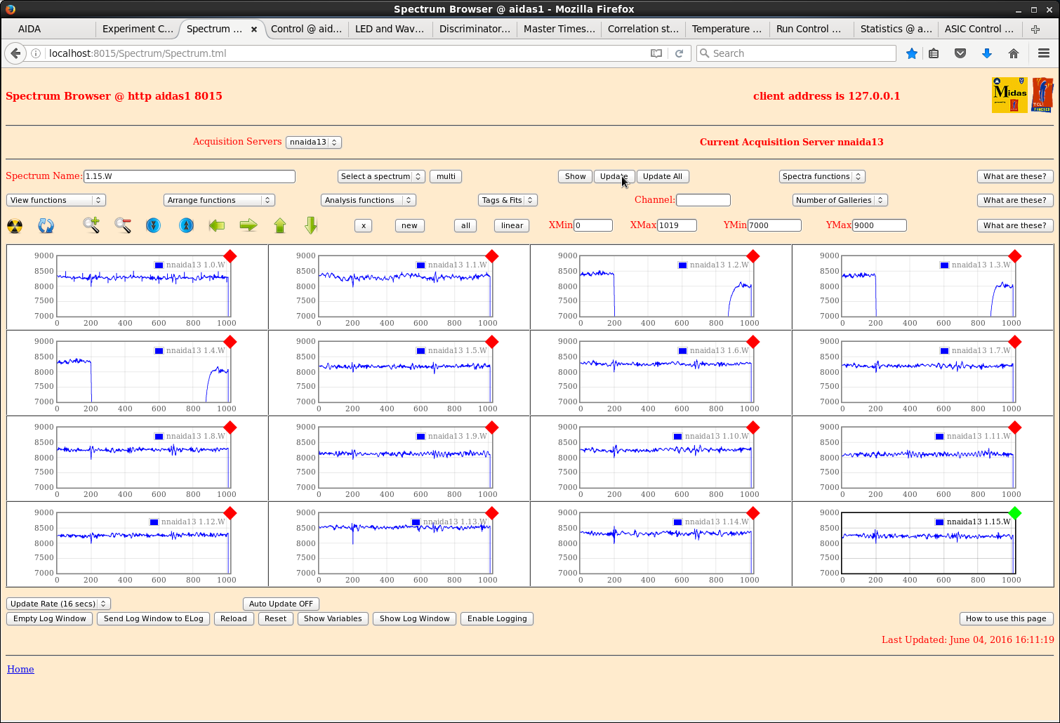
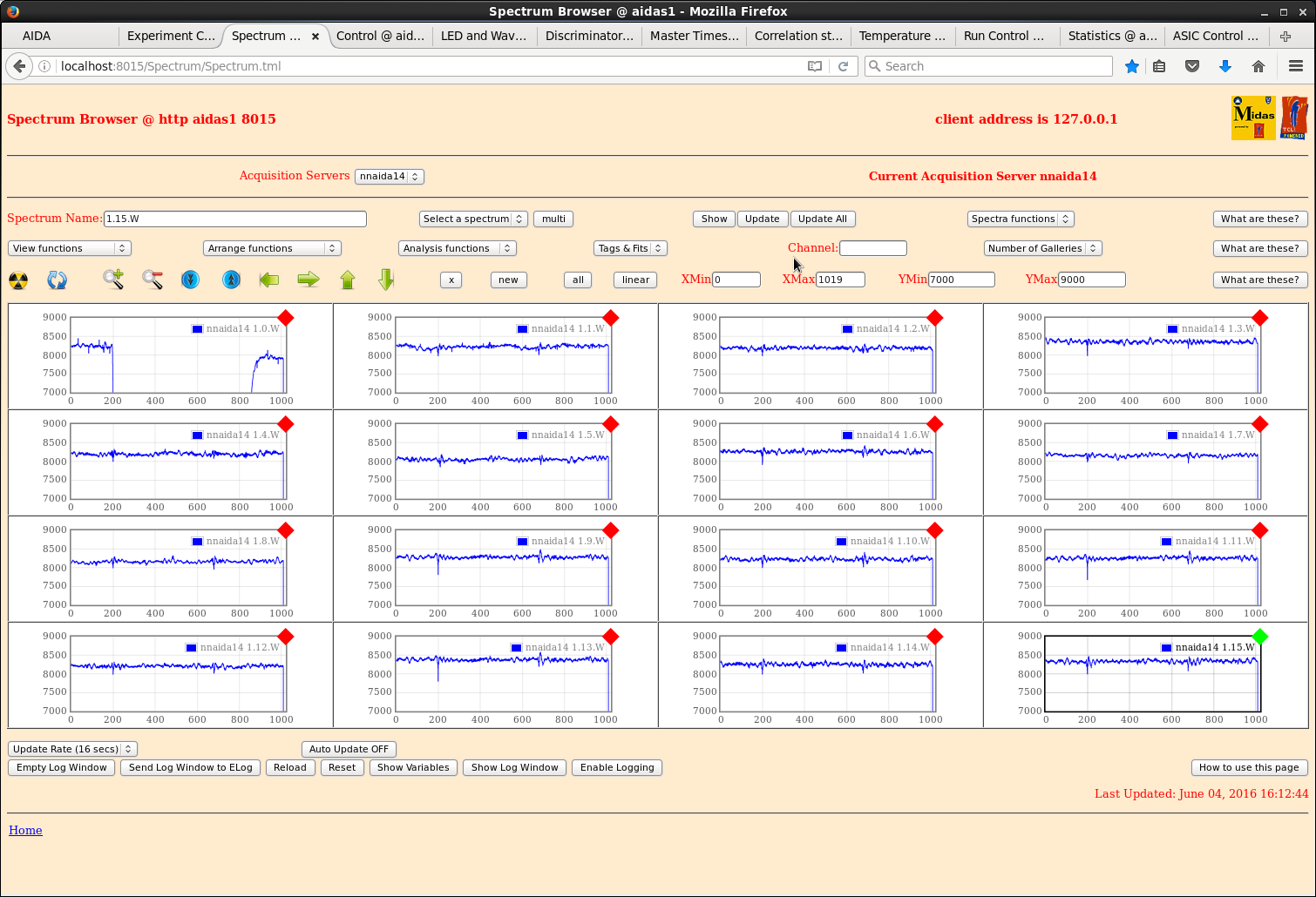
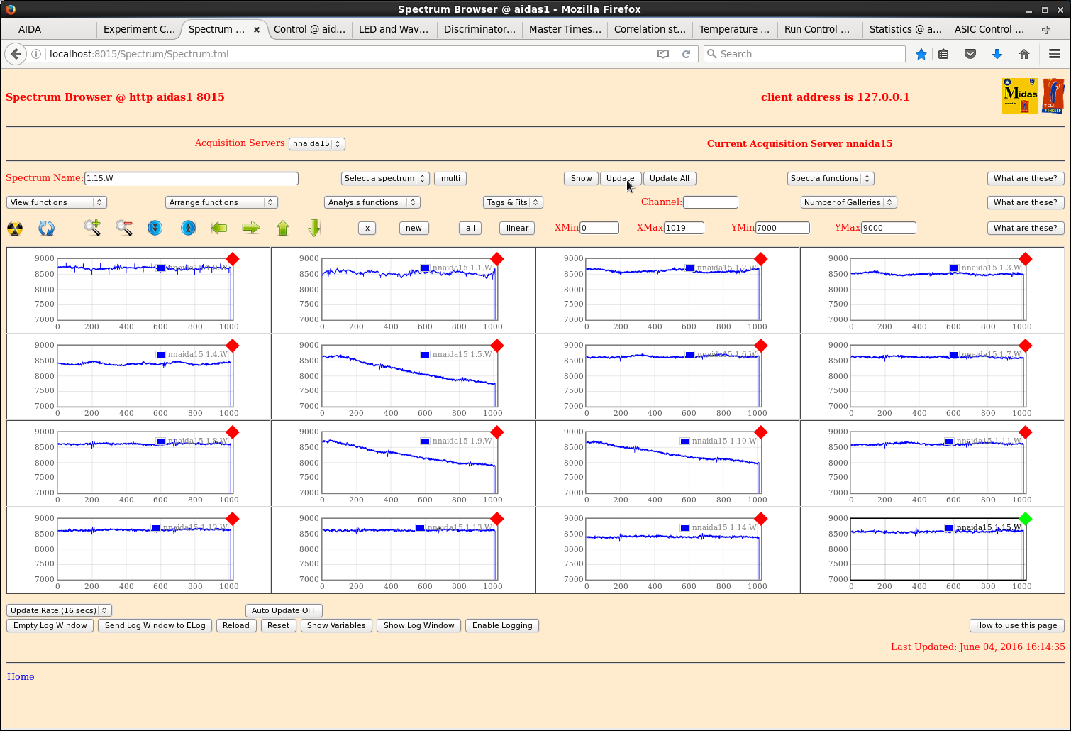
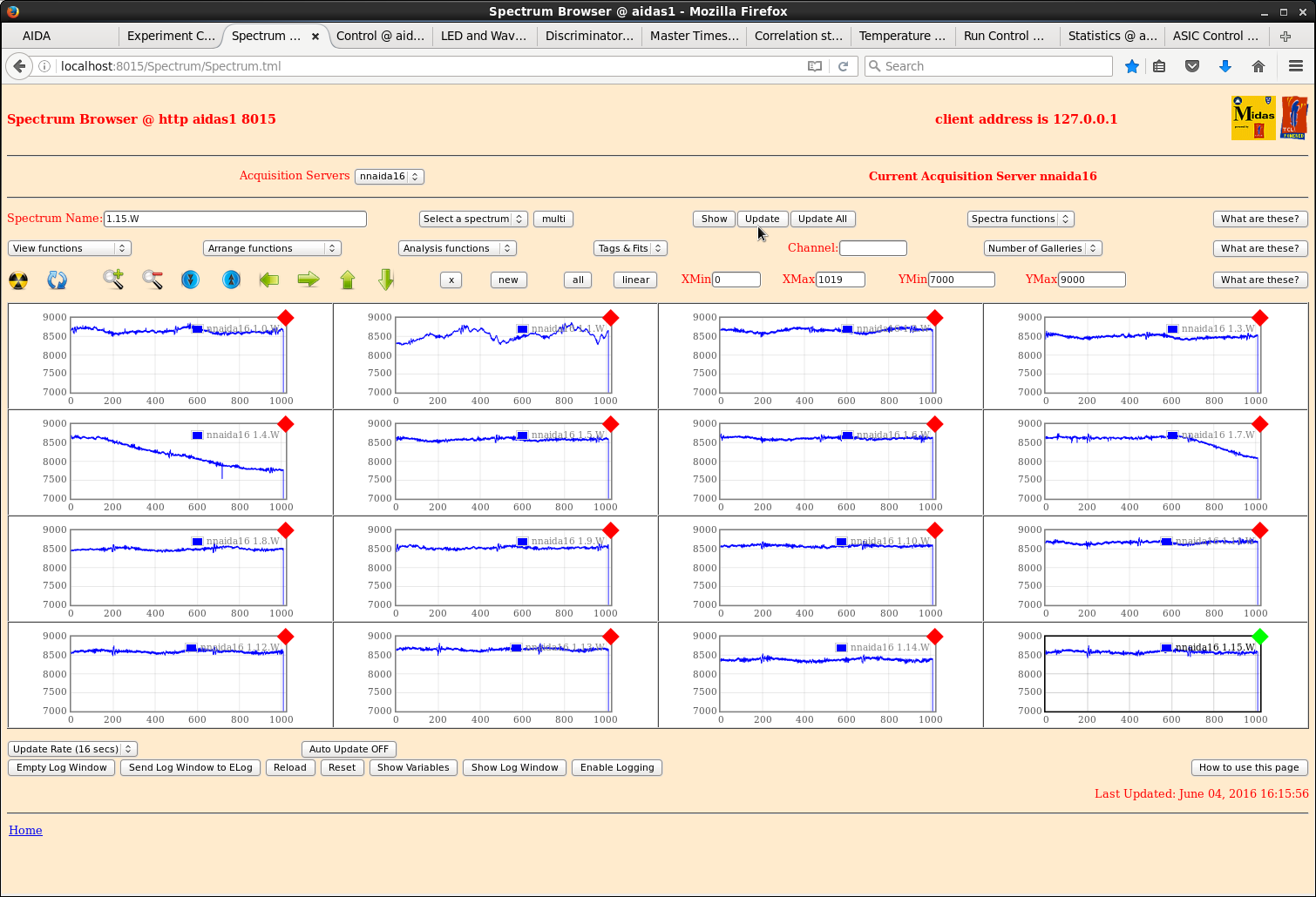
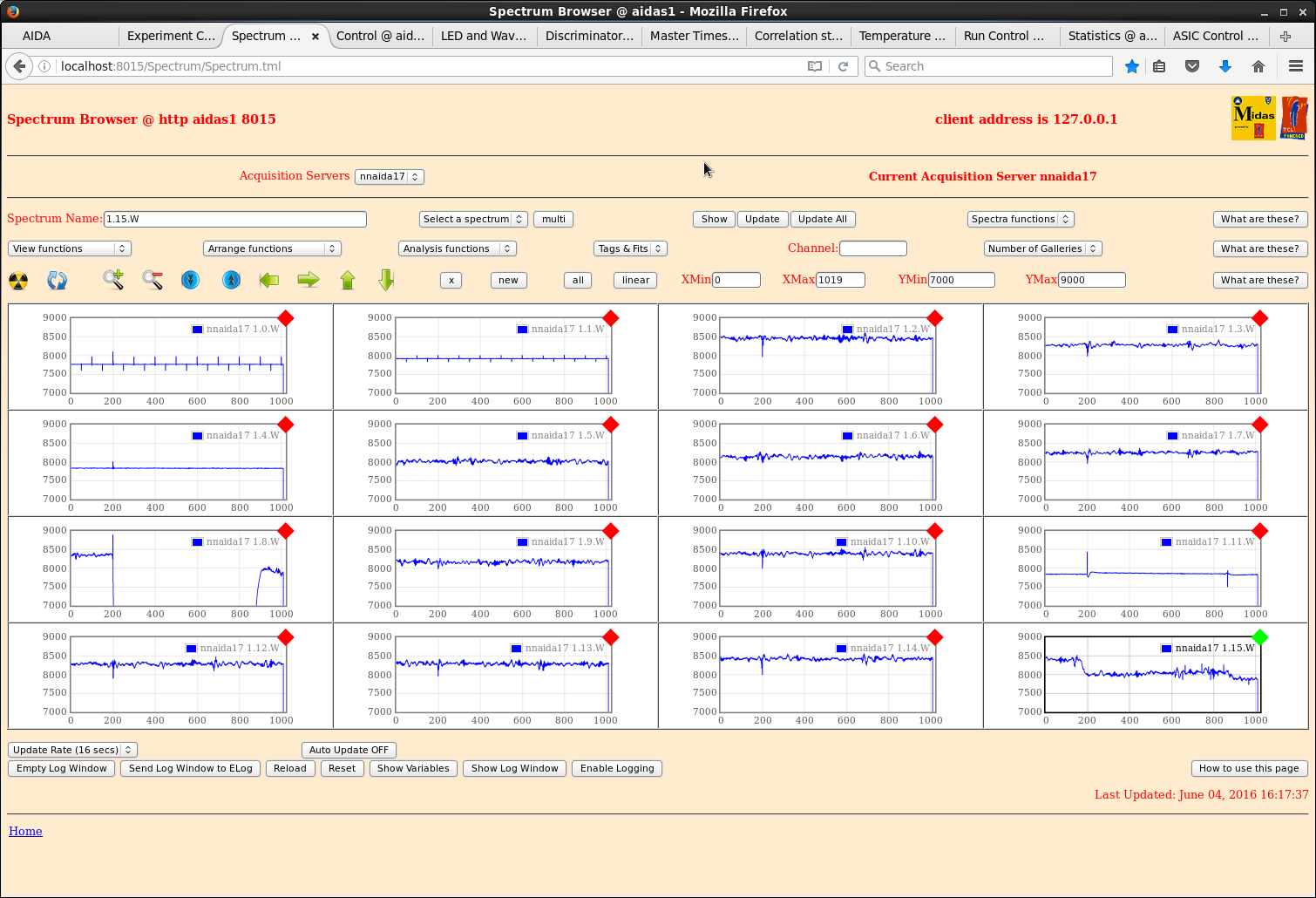
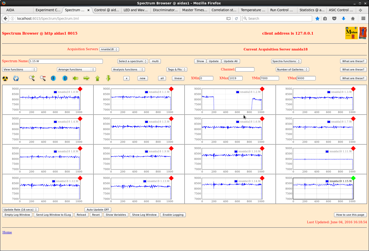
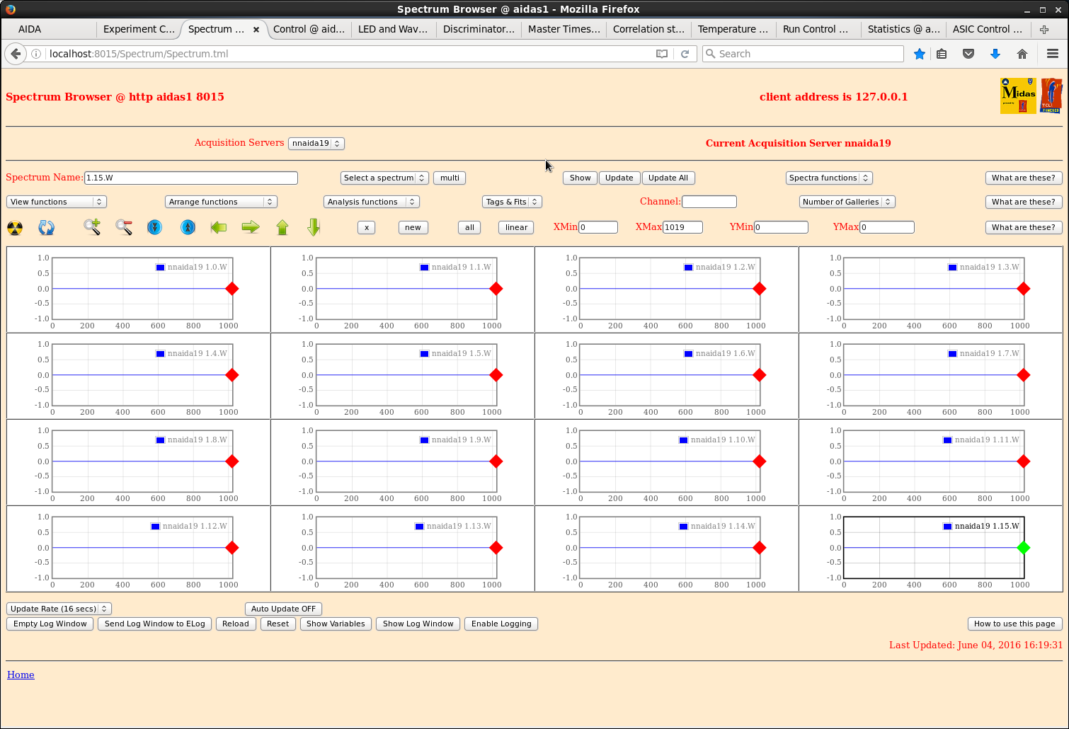
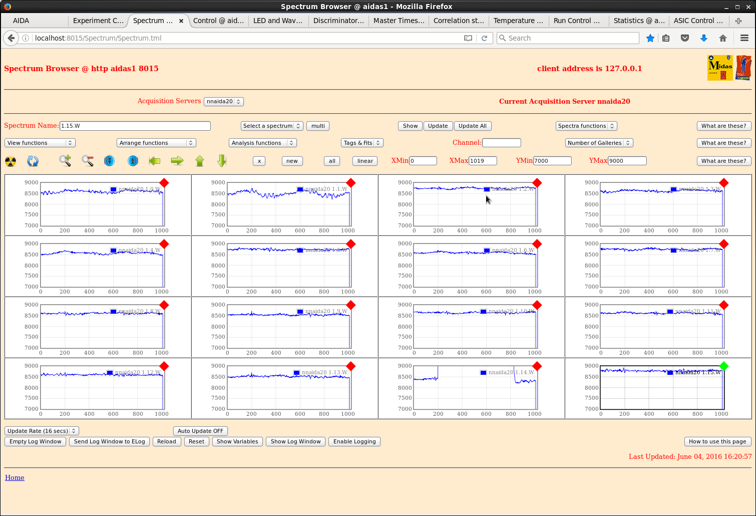
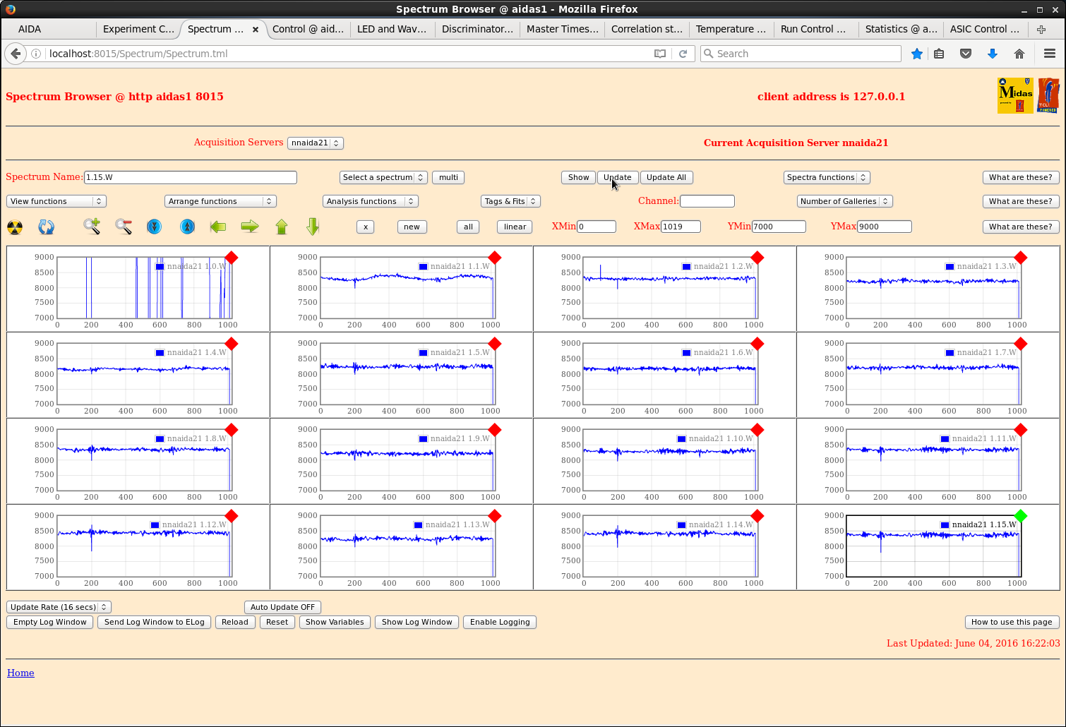
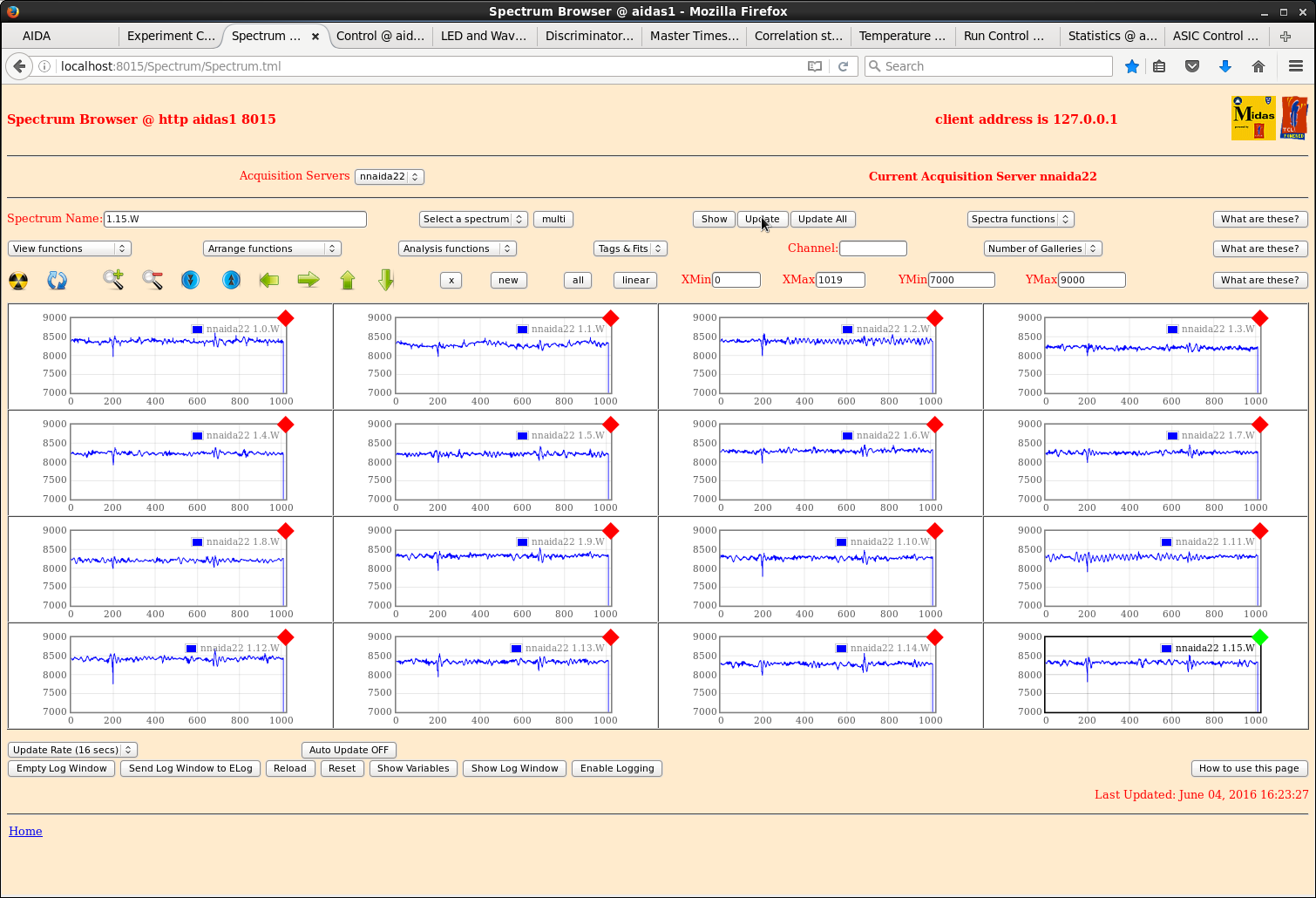
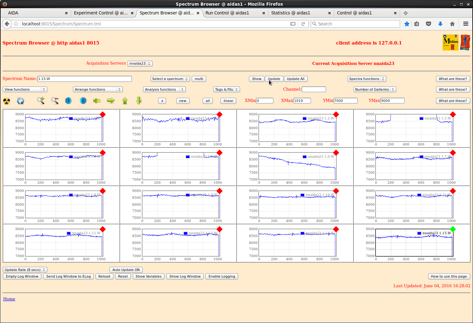
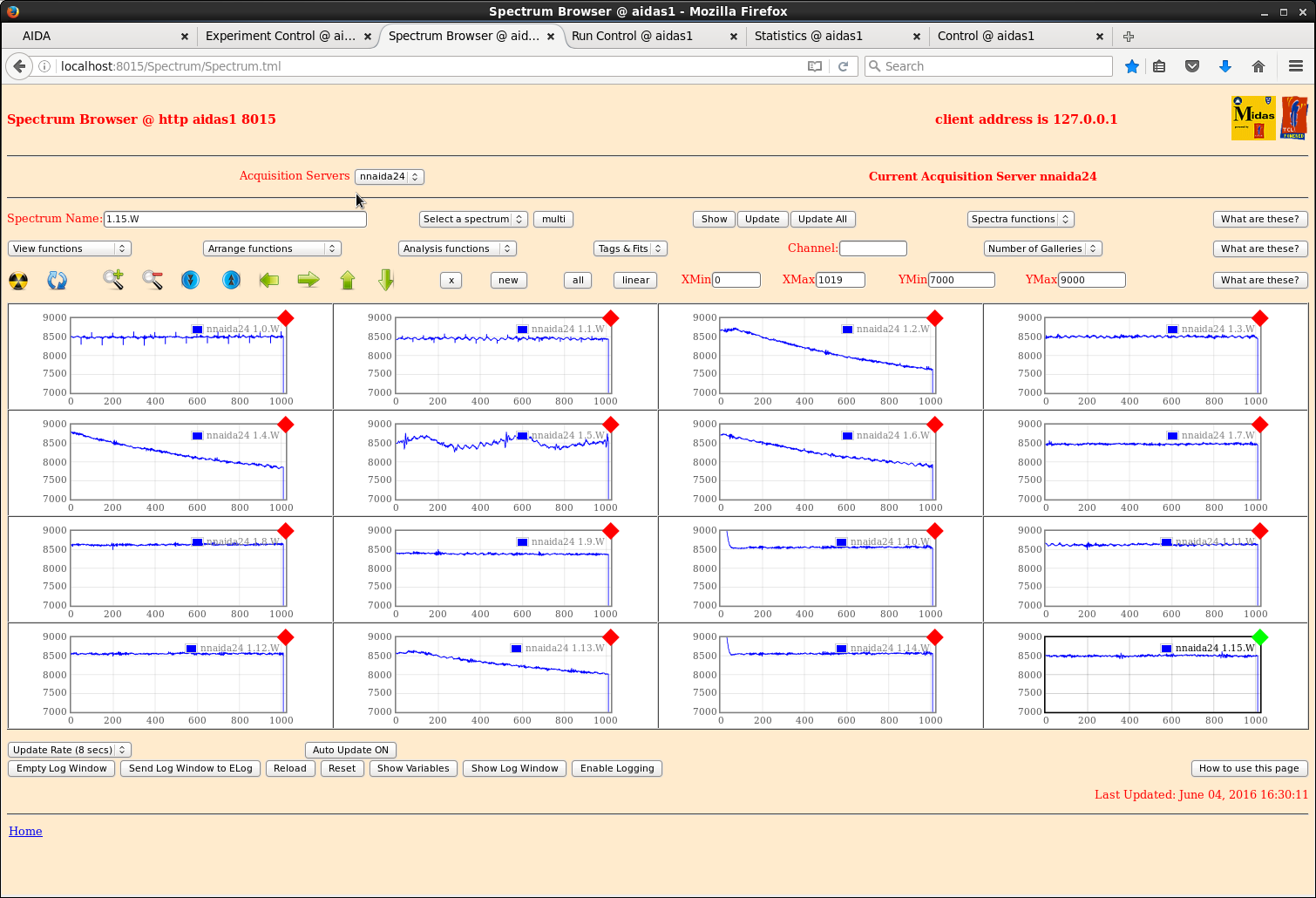
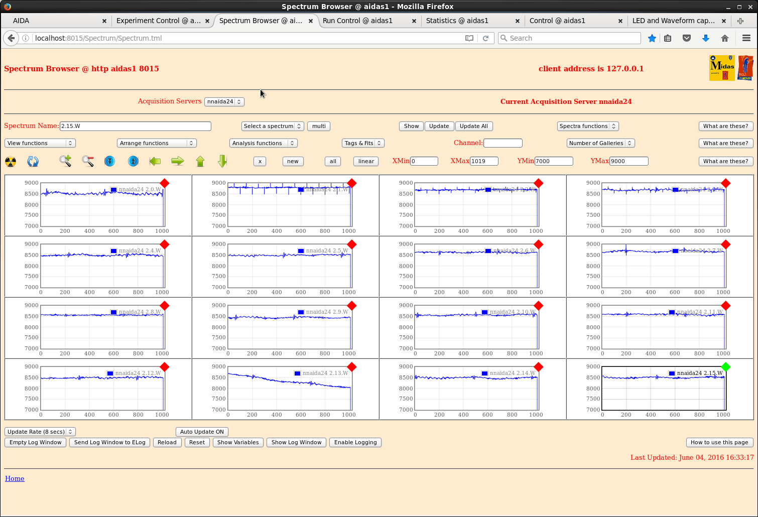
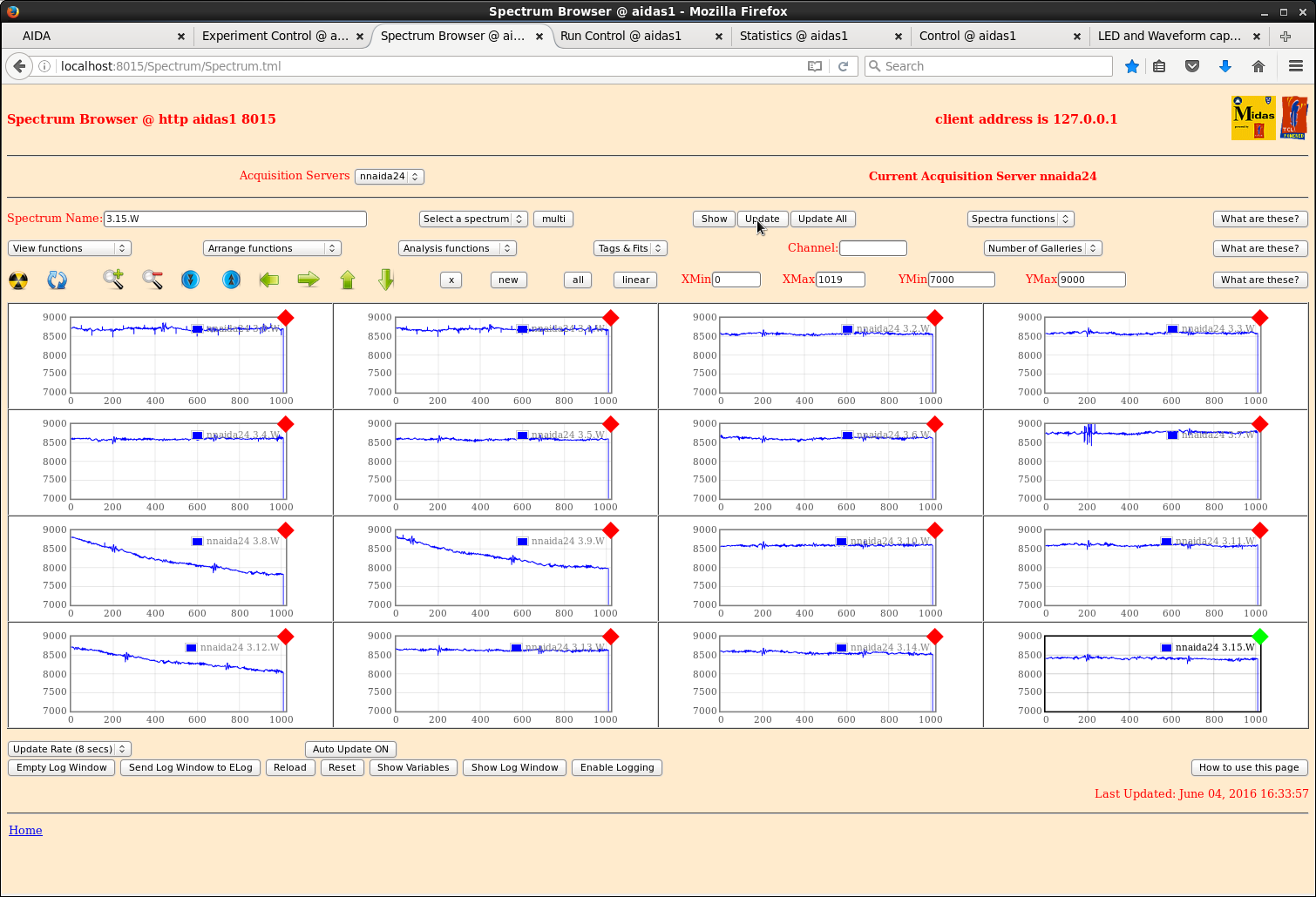
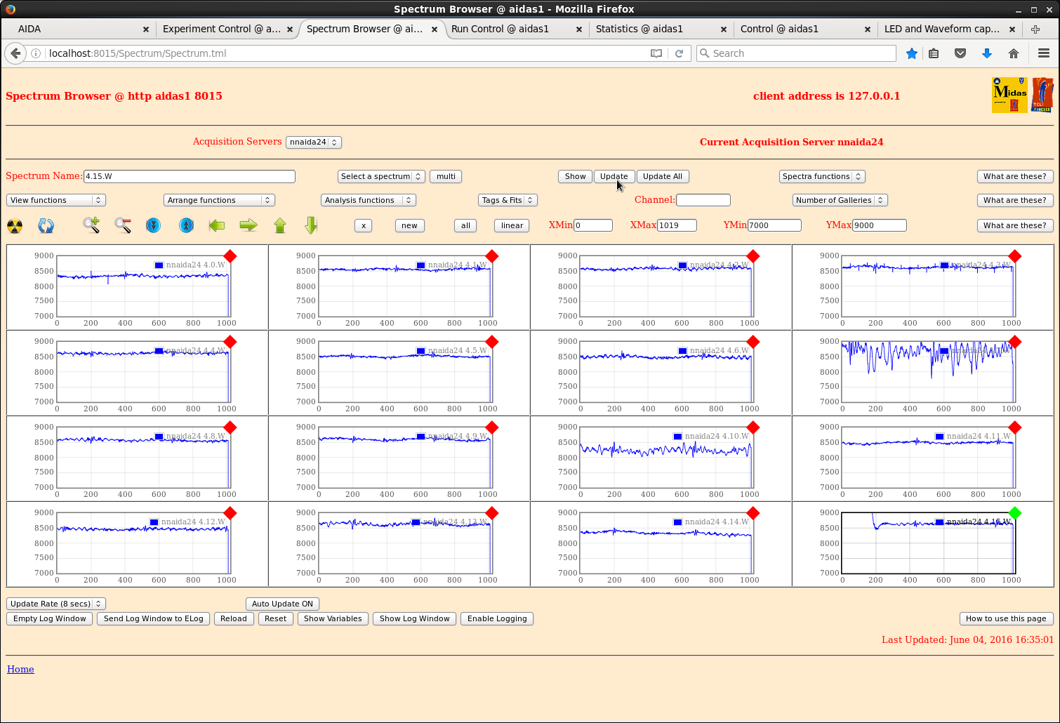
Attachments  1-23 AIDA FEE64s nnaida1-nnaida23 ASIC #1 waveforms

Attachments 24-27 AIDA FEE64 nnaida24 ASIC #1 - #4 waveforms

Common y-scale 7000-9000, xscale ~1000 samples @ 20ns/sample

All *L and *W histograms saved to /MIDAS/SpecData at c. 17.00 Saturday 4 June 2016

Note

1) BNC PB-4 Pulser amplitude 90,000, x5 attenuator, frequency c. 5Hz + ~40kBq 60Co source
placed on AIDA snout

2) EURICA closed |
| Attachment 1: 101.png
|
|
| Attachment 2: 102.png
|
|
| Attachment 3: 103.png
|
|
| Attachment 4: 104.png
|
|
| Attachment 5: 105.png
|
|
| Attachment 6: 106.png
|
|
| Attachment 7: 107.png
|
|
| Attachment 8: 108.png
|
|
| Attachment 9: 109.png
|
|
| Attachment 10: 110.png
|
|
| Attachment 11: 111.png
|
|
| Attachment 12: 112.png
|
|
| Attachment 13: 113.png
|
|
| Attachment 14: 114.png
|
|
| Attachment 15: 115.png
|
|
| Attachment 16: 116.png
|
|
| Attachment 17: 117.png
|
|
| Attachment 18: 118.png
|
|
| Attachment 19: 119.png
|
|
| Attachment 20: 120.png
|
|
| Attachment 21: 121.png
|
|
| Attachment 22: 122.png
|
|
| Attachment 23: 123.png
|
|
| Attachment 24: 124.png
|
|
| Attachment 25: 125.png
|
|
| Attachment 26: 126.png
|
|
| Attachment 27: 127.png
|
|
|
|
861
|
Thu Nov 14 07:57:46 2019 |
TD | AIDA moved from in-beam position at F11 |
To make room for the installation of an MR-TOF device at F11, AIDA and DTAS have been removed
from their in-beam position at F11.

The AIDA network and DTAS/BRIKEN optic fibre cables have been coiled and tied to the E17 stairwell
barrier. |
|
|
946
|
Wed Apr 10 16:45:59 2024 |
TD | AIDA interlock |
Honeywell HSS DPS sensor information https://elog.ph.ed.ac.uk/AIDA/932

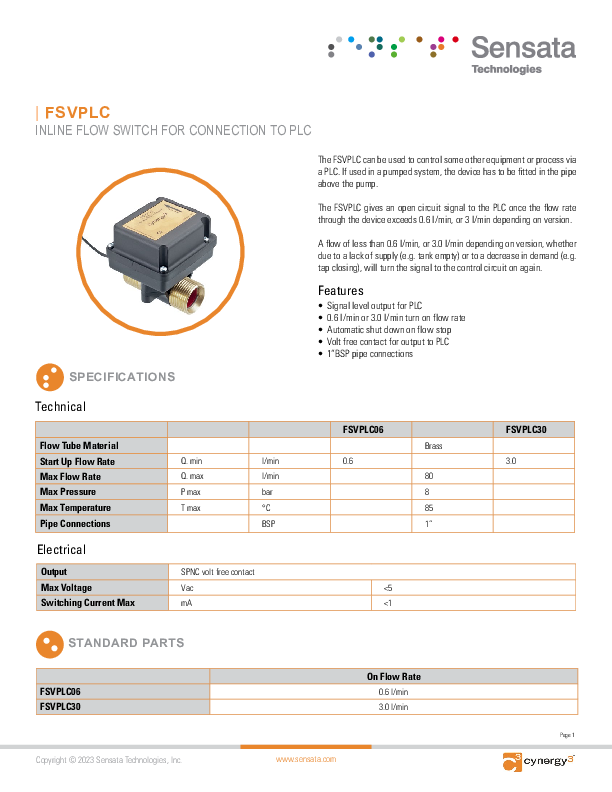
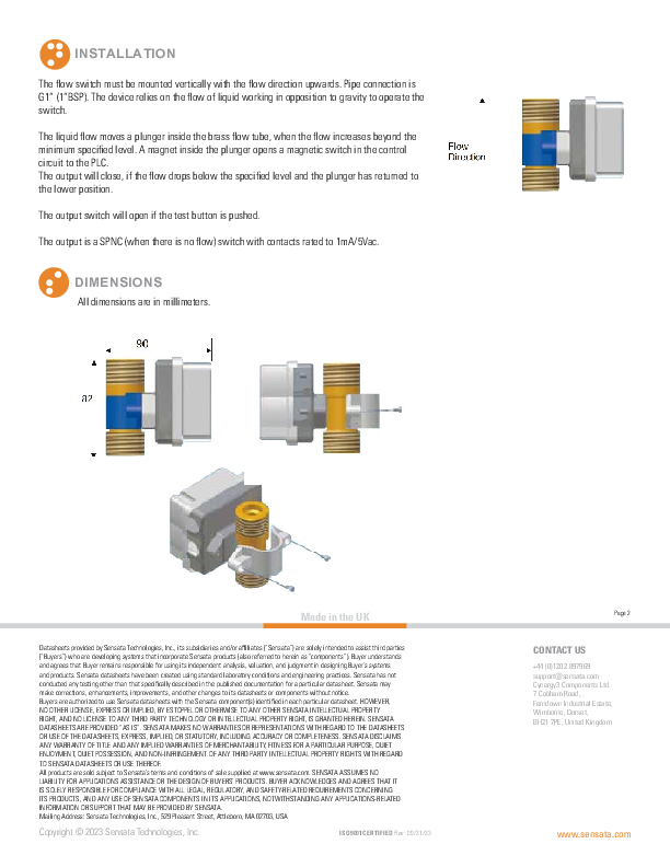
Cynergy3 FSVPLC - attachment 1


Honeywell sensor - red LED continuously lit - OK

Connecting FSVPLC to the interlock box causes green power LED of 24V adaptor to blink ~Hz frequency indicating a fault condition |
| Attachment 1: cynergy3-fsvplc-v3.pdf
|
|
|
|
404
|
Thu Oct 27 10:57:49 2016 |
TD | AIDA data readout |
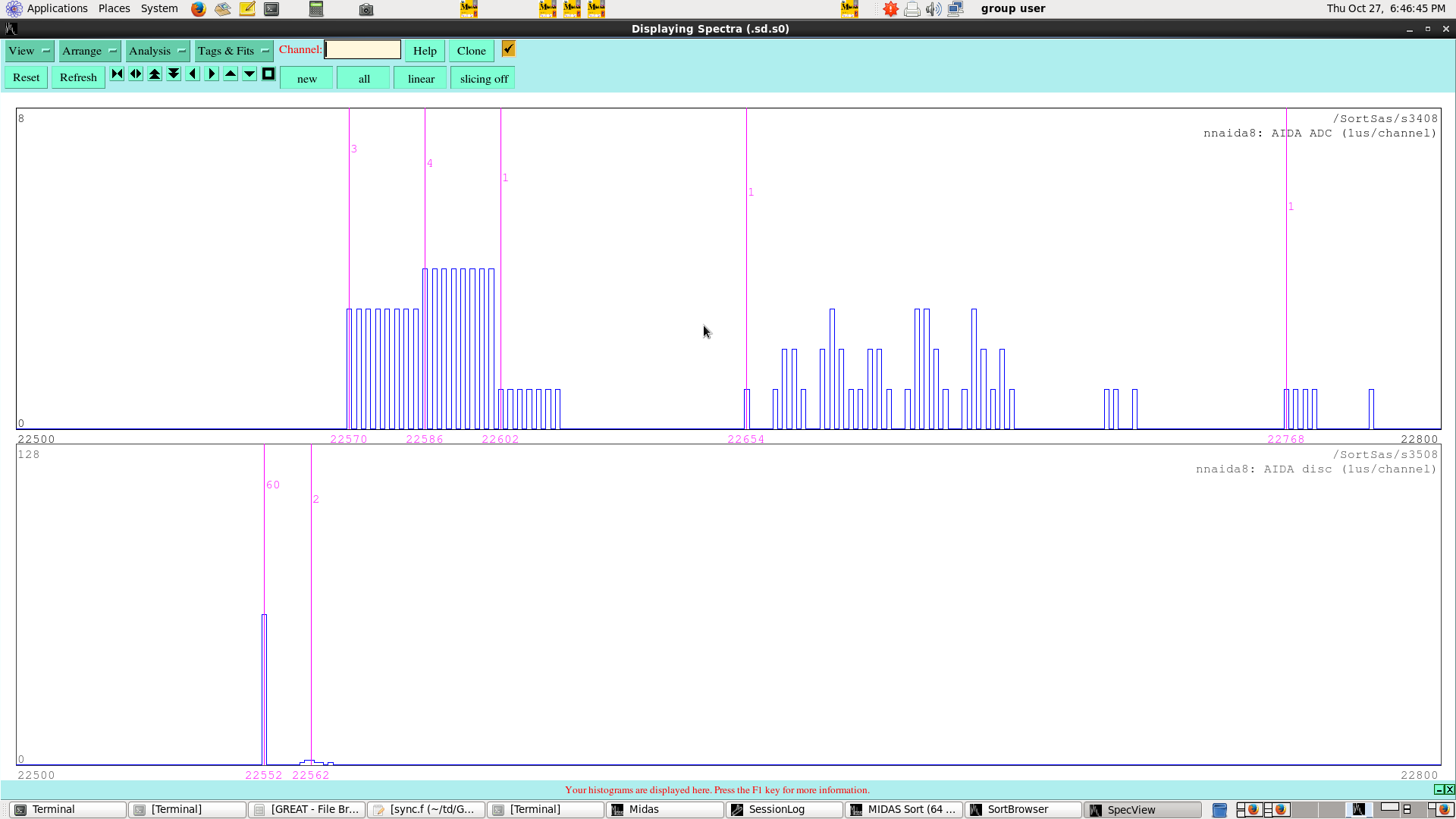
Developing real-time AIDA data synchronisation test using MIDASsort

To illustrate AIDA readout, ADC and discriminator data from a pulser event is plotted as a function
of the 100MHz AIDA internal timestamp (1us/channel)

Attachment 1 -    nnaida8  number of ADC and discriminator data items
Attachment 2 - nnaida1-24  number of ADC and discriminator data items
Attachment 3 - 4*(FEE64 module # - 1) + ASIC # (ADC channels 0-95, disc channels 100-195) versus timestamp
(1us/channel)

The spectra clearly illustrate

- 500kHz ADC readout cycle
- discriminator readout precedes ADC readout by ~18us (this figure will be shaping time dependent)
- after-pulse due to pulser injection via simple charge terminator (no pole zero correction)
  ~84us after start of ADC readout (this figure will be pulser decay time and shaping time dependent)

Note events were identified (delimited) by time periods > 2us between successive ADC data items |
| Attachment 1: 100.png
|
|
| Attachment 2: 101.png
|

|
| Attachment 3: 102.png
|

|
|
|
55
|
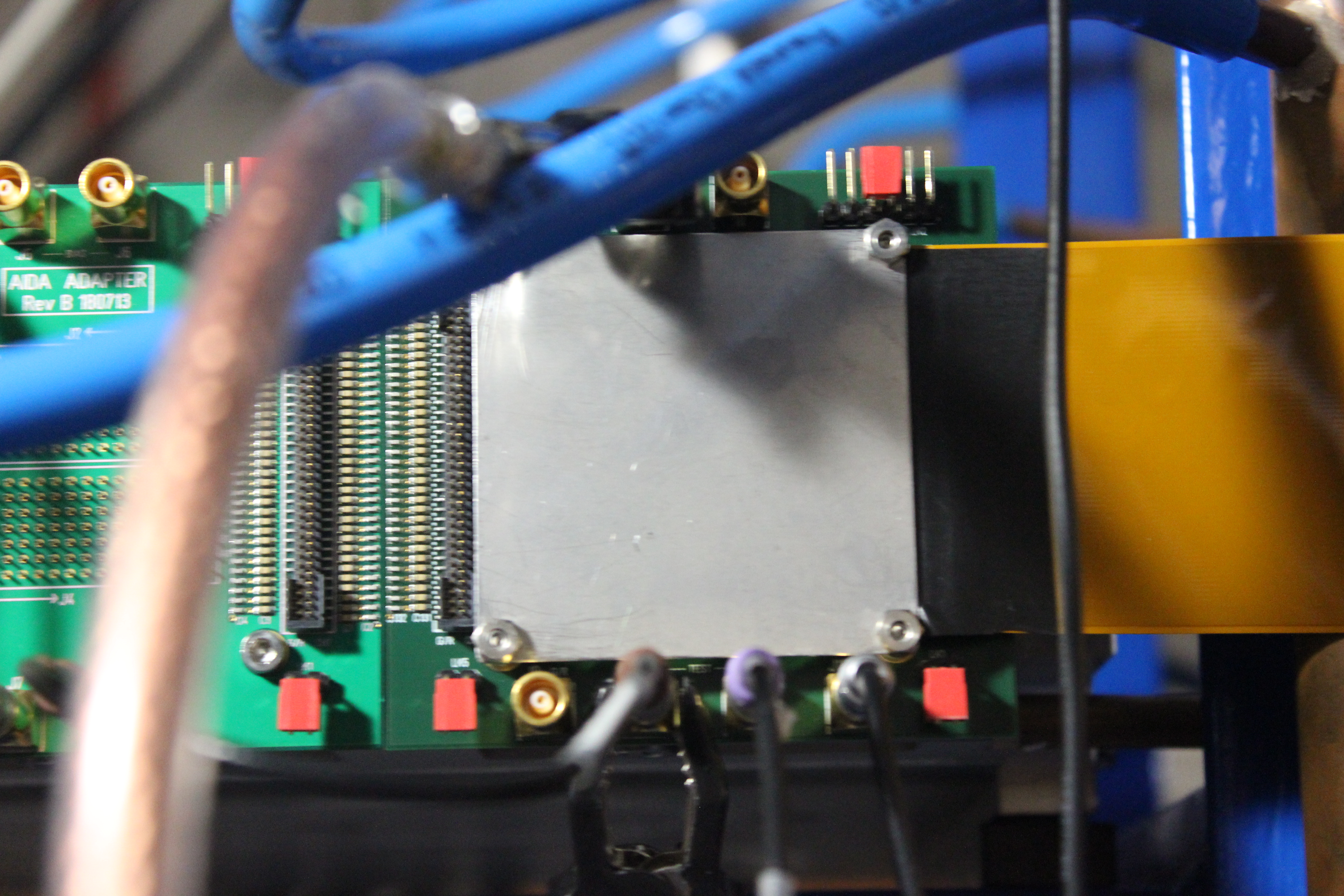
Mon Mar 9 16:51:26 2015 |
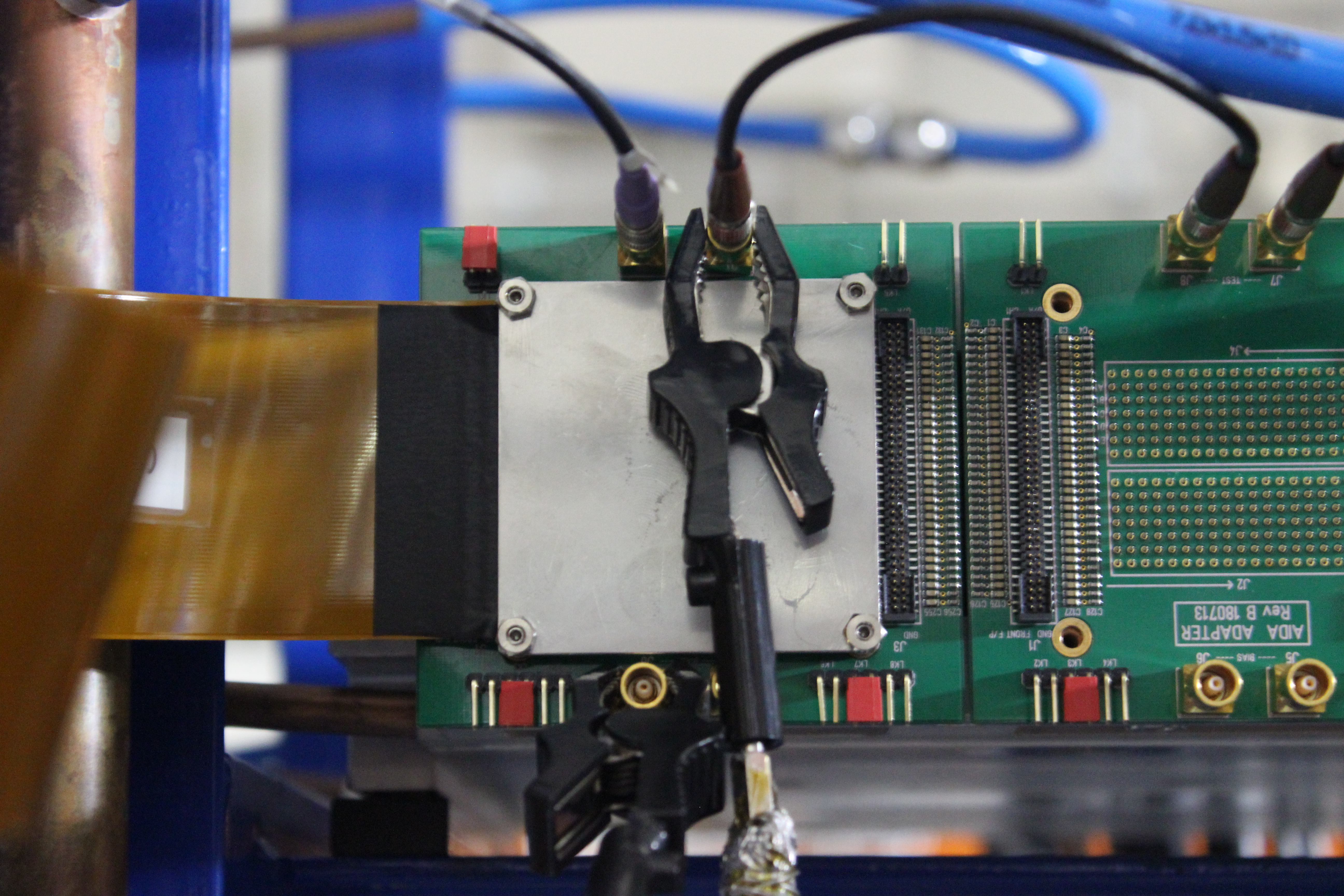
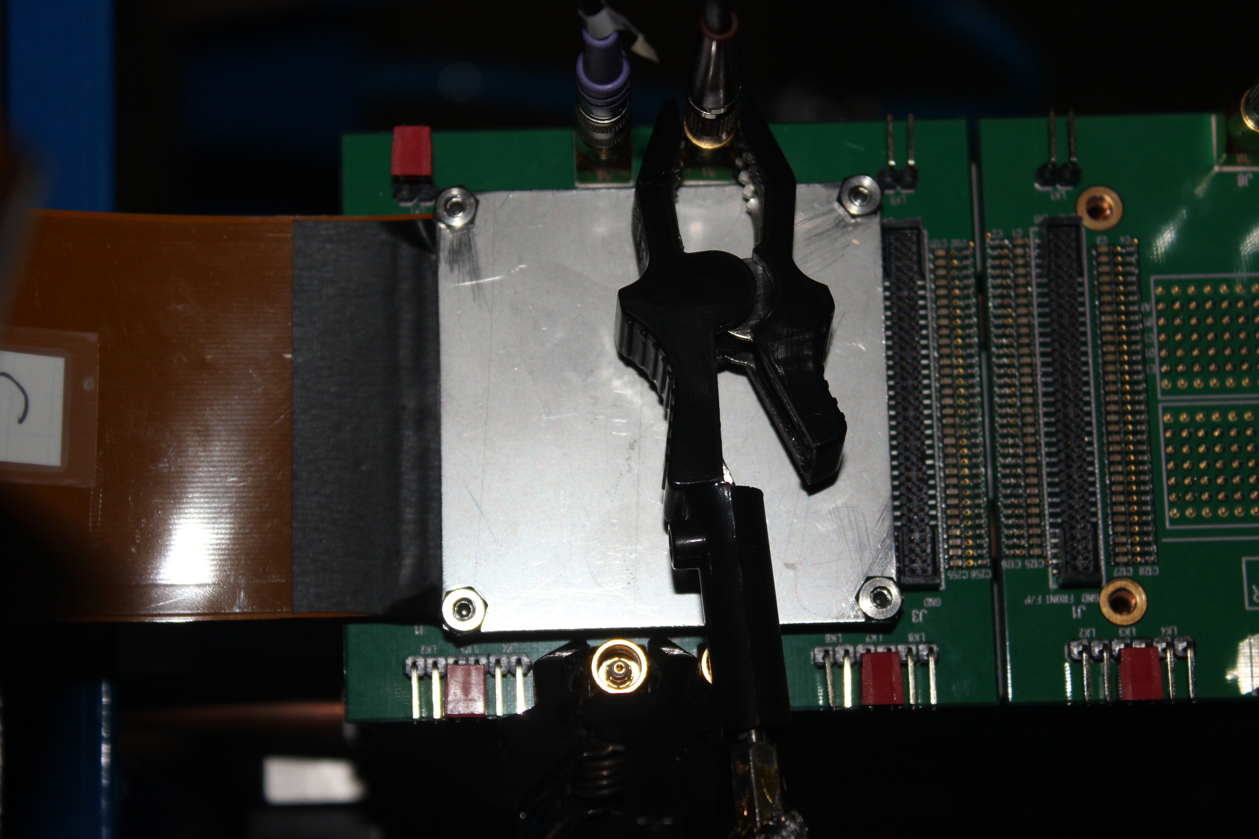
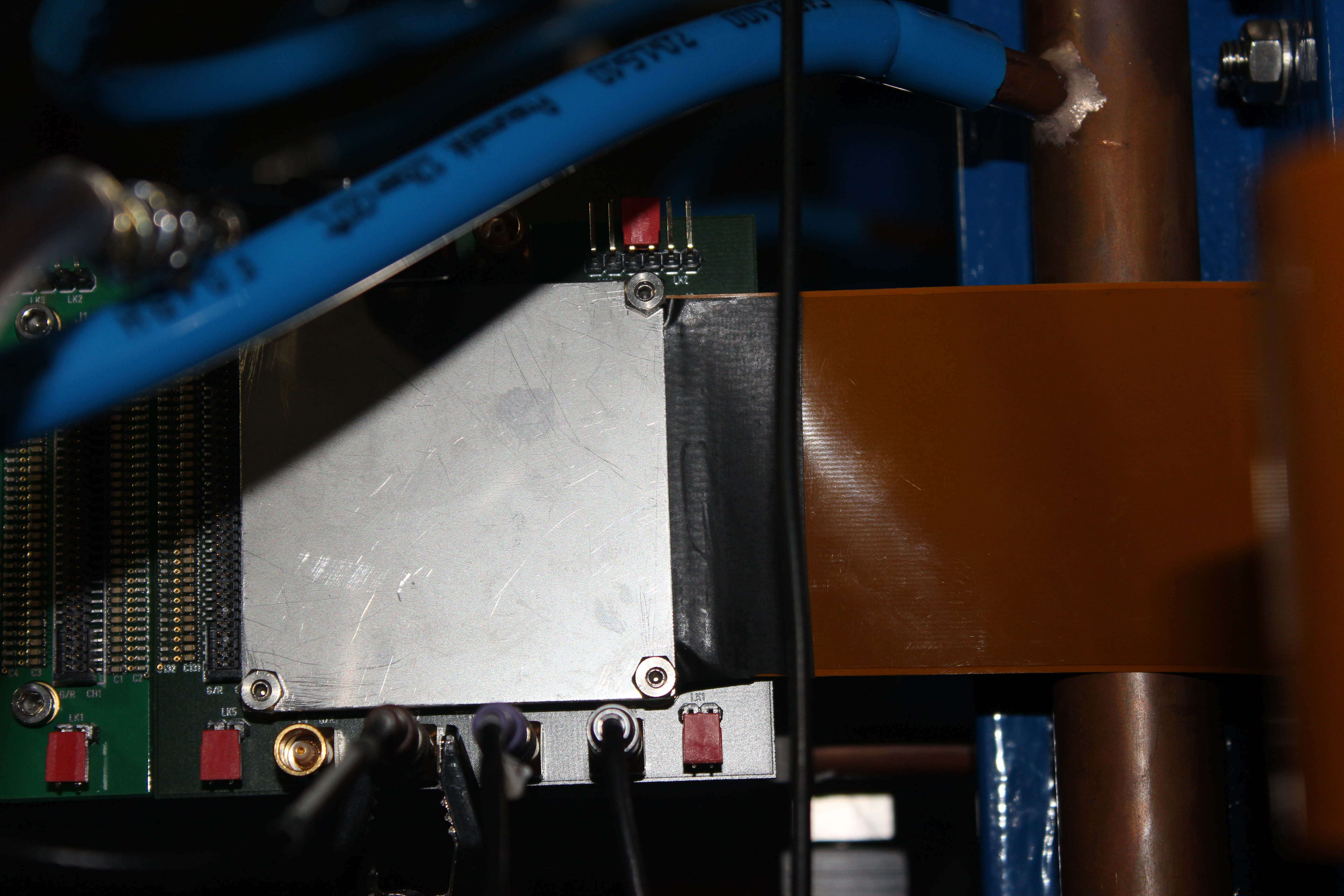
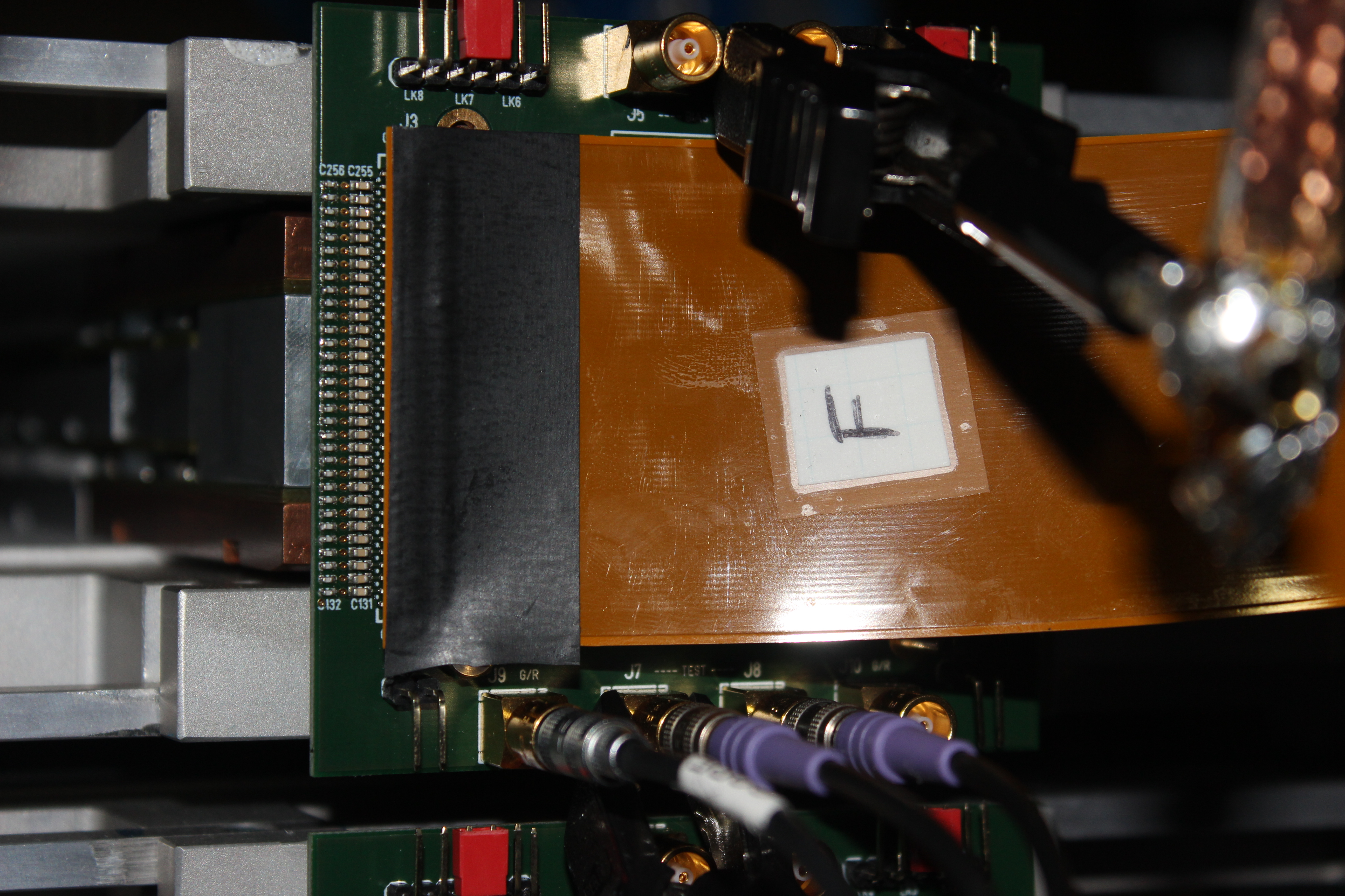
TD | AIDA adaptor PCB configuration - RIKEN - Feb 2015 |
|
| Attachment 1: IMG_2781.JPG
|
|
| Attachment 2: IMG_2782.JPG
|
|
| Attachment 3: IMG_2783.JPG
|
|
| Attachment 4: IMG_2784.JPG
|
|
| Attachment 5: IMG_2787.JPG
|
|
| Attachment 6: IMG_2796.JPG
|
|
|
|
931
|
Mon Dec 4 10:34:48 2023 |
NH | AIDA Todo for 11.12.23 |
This is a short list of things todo or check before the test beam time on 11.12.23
Updated after 15:00 CET meeting

1. Replace water interlock
- Also allows testing of AIDA for 24h+

2. Decide on snout configuration: 1 or 2 BB18s (plus BB7 plus bPlastic)
  It is U so if we put 2 we could damage 2 instead of just 1 (of course we try to be careful)
  To decide which bPlas is installed (only 1 will be bothered): Upstream is preferred by HA
  Install Peter's light blocking frame between bPlastic and AIDA

3. Replace aida04 with a working FEE64
  Important as aida04 is in deadtime and not very useful

4. Investigate/replace aida06
  Less urgent because 2 strips and runs with 0 dead time

5. If 2 BB18s, add another 8 working FEE64s to the system
  Note: Cannot do 2BB18s and 1BB7 (cannot power/cool 17 FEEs)

6. Test AIDA firmware fix for individual ASIC controls (especially if BB7<->AIDA will be tested)
  BB7<->AIDA will not be tested probably, as PCB will not arrive.
  Still good to check if possible

7. Decide on FEE to take pulser (assuming no distribution/inverter available)
Test implant response with pulser and SC41 trigger? |
|
|
5
|
Thu Sep 11 17:29:59 2014 |
Tom Davinson | AIDA Tests at STFC DL - To Do list |
In no particular order of priority:

1) Vary ASIC V_DD=3.3V within +/-10% operating range

2) Use 'clean' floating high voltage detector bias
    - check polarity
    - is there a difference between detector local
      ground on p+n junction or n+n ohmic sides of DSSSD?
    - common or isolated detector local ground for multiple DSSSDs?
    - RFQ submitted for 1x CAEN N1419
    - additional filtering for Emco Q05-5?
    - other?

3) Backtrack changes to date
     - Kapton PCB mods
     - PSU set points
     - Standard FEE64 PSUs -> linearly regulated PSUs

4) Evaluate effect of ASIC parameters 'Ibias preamp SF' and 'Ibias preamp' on noise

5) Evaluate effect of ASIC parameter 'preAmp reference' on stability of positive and
   negative input configurations

Comments and corrections welcome! |