| |
ID |
Date |
Author |
Subject |
|
|
7
|
Thu Sep 20 09:16:31 2018 |
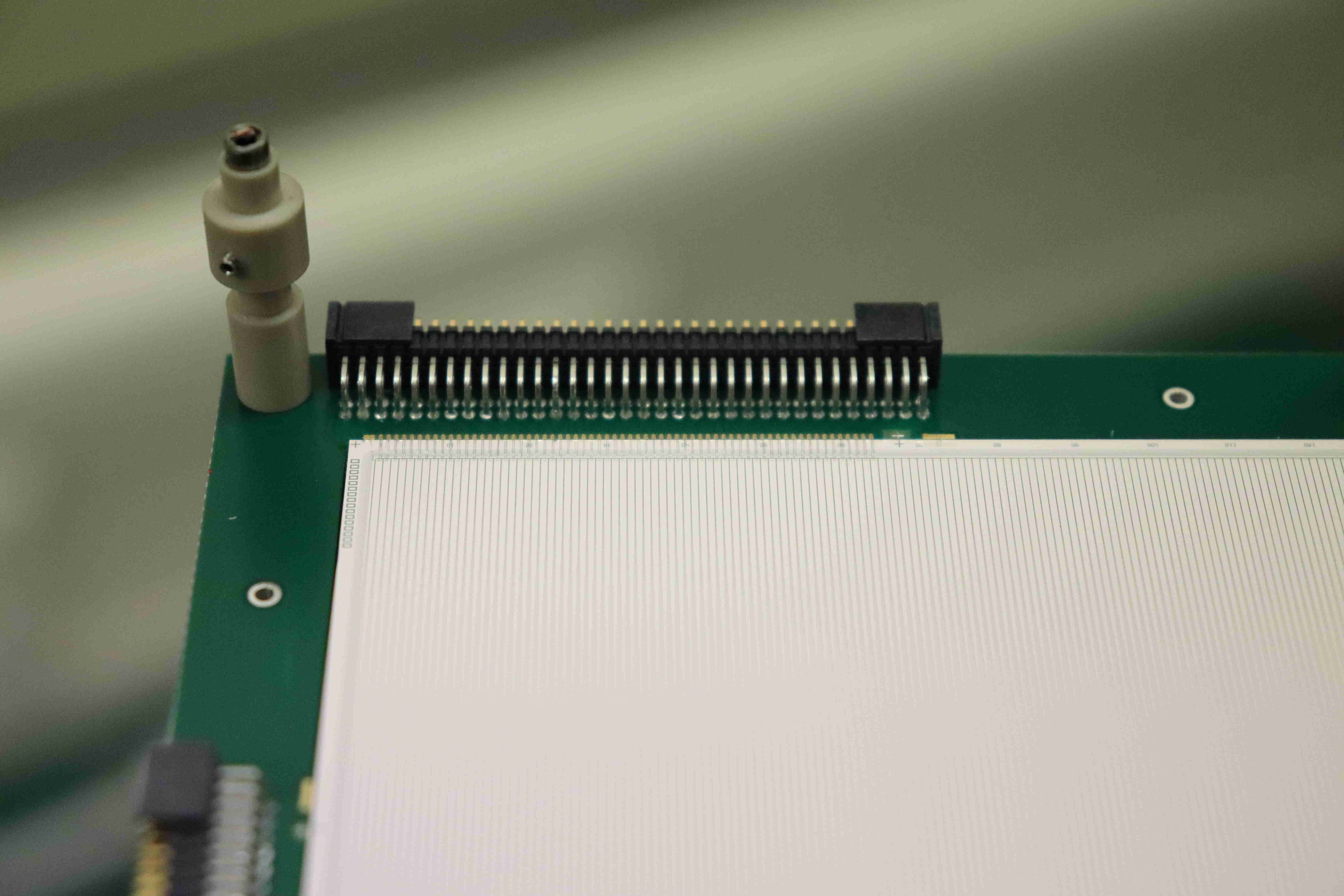
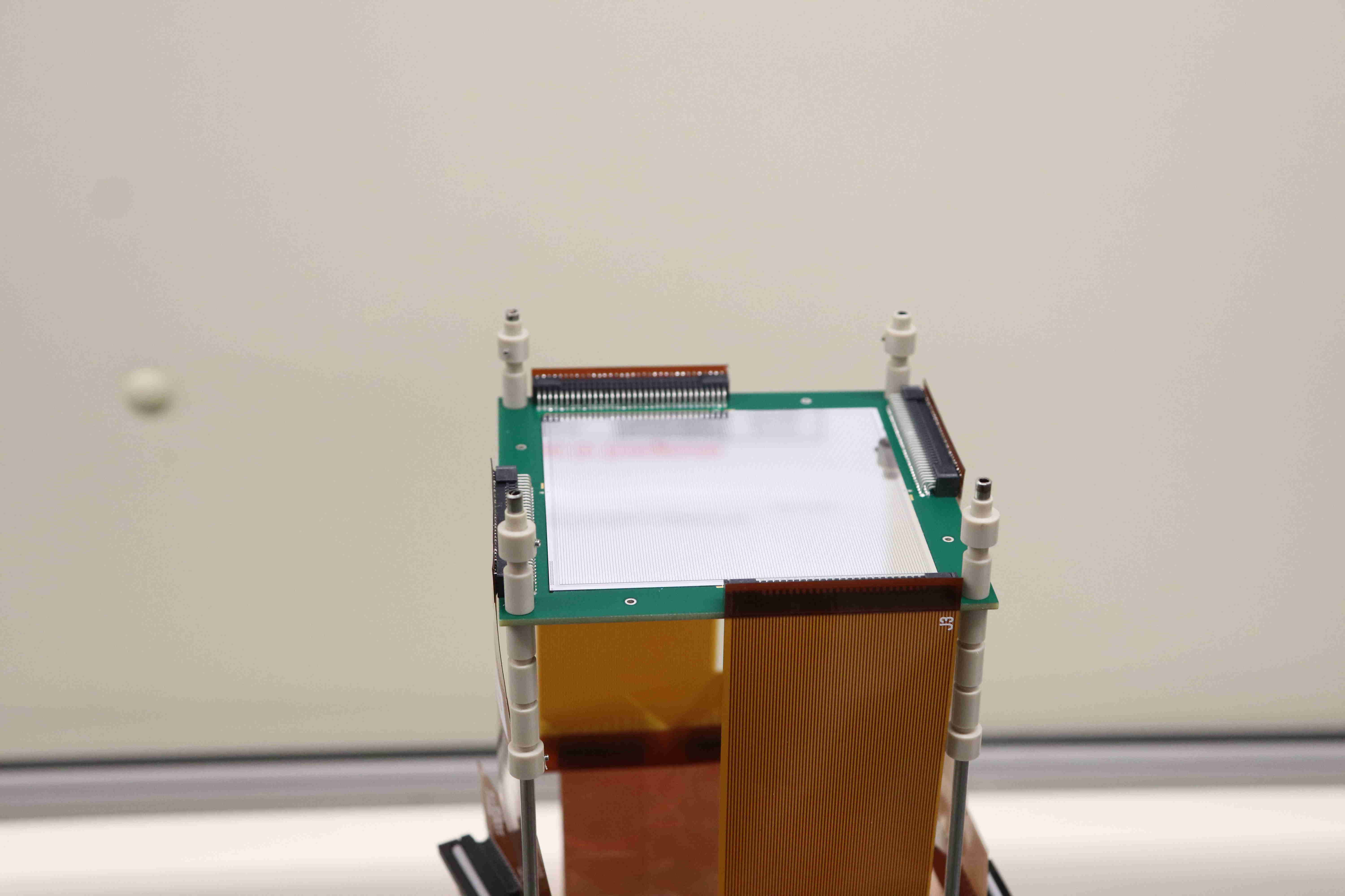
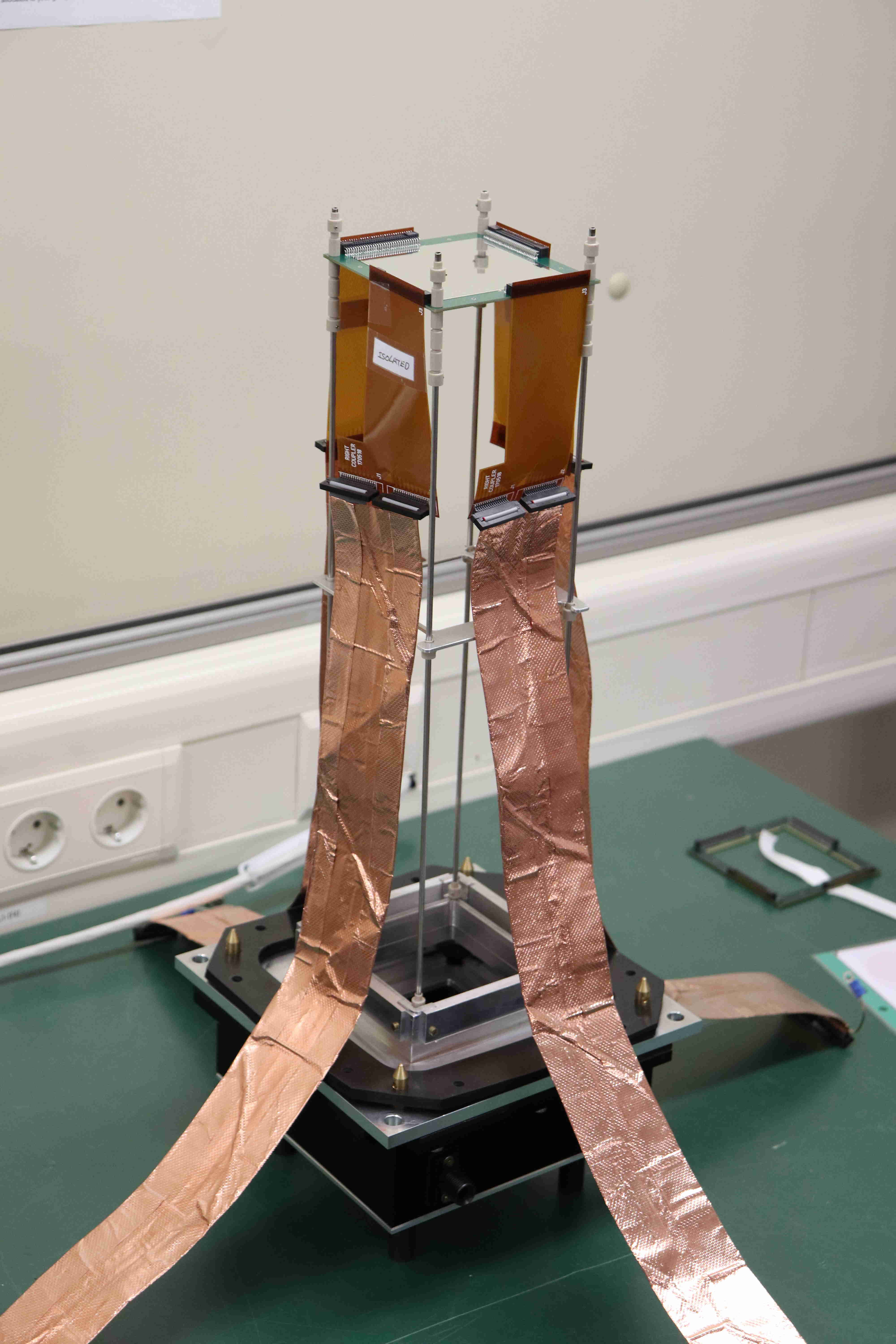
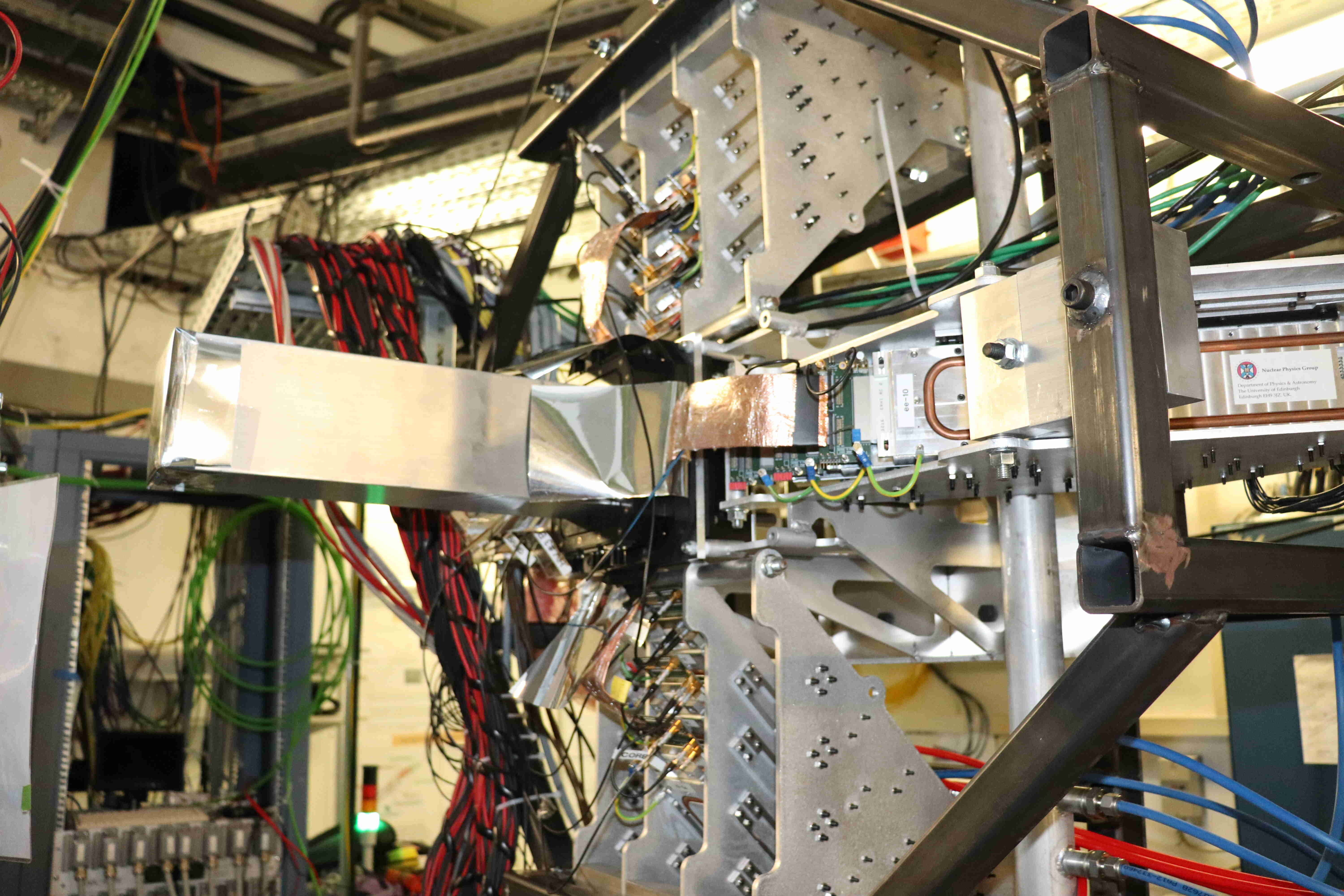
TD | Images of AIDA setup for DESPEC |
Attachment 1 - detail of MSL type BB18(DS)-1000 p+n junction side strips, bias ring, multiple guard rings, filed
plates and bond wires

Attachment 2 - MSL type BB18(DS)-1000 with Kapton PCBs attached

Attachment 3 - MSL type BB18(DS)-1000 with Kapton PCBs + 3M 1245 copper foil-screened Samtec FTSH ribbon cables
attached

Attachment 4 - AIDA snout installed (with 1x DSSSD) with cabling to 4x FEE64s in AIDA support assembly

Attachment 5 - AIDA + FATIMA array

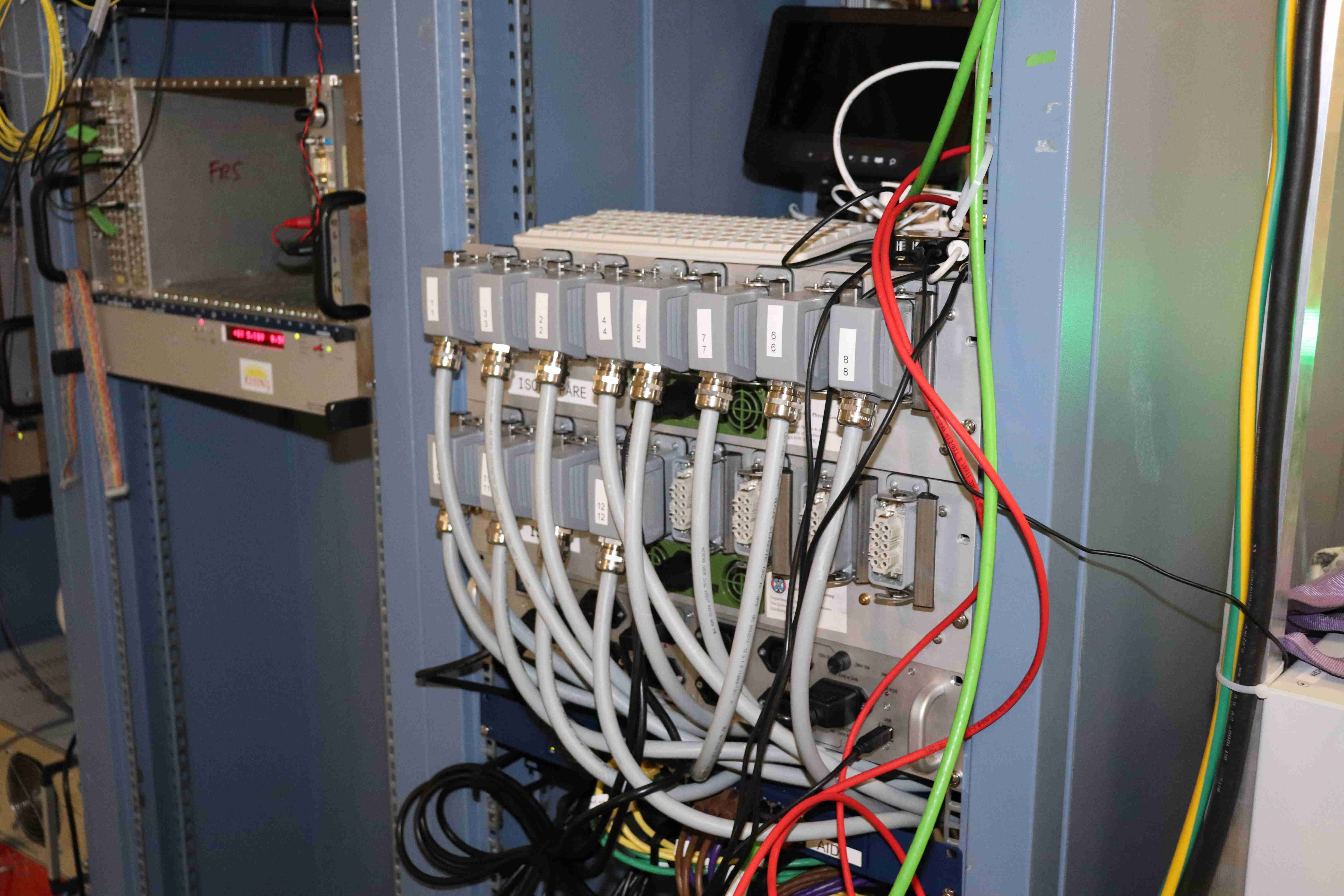
Attachment 6 - AIDA FEE64 PSUs, network switch, USB-controlled ac mains relay

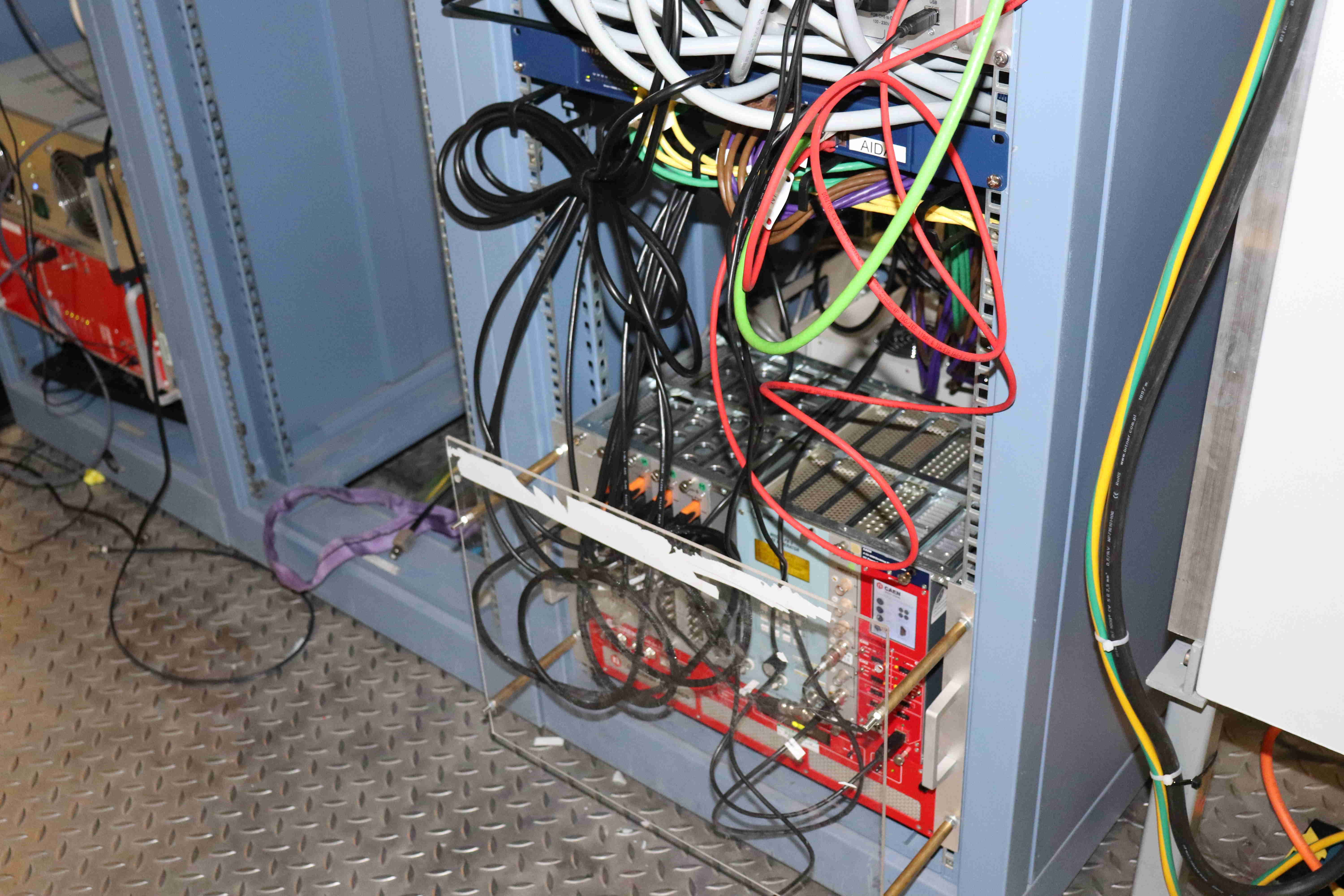
Attachment 7 - AIDA MACBs, pulser, detector bias

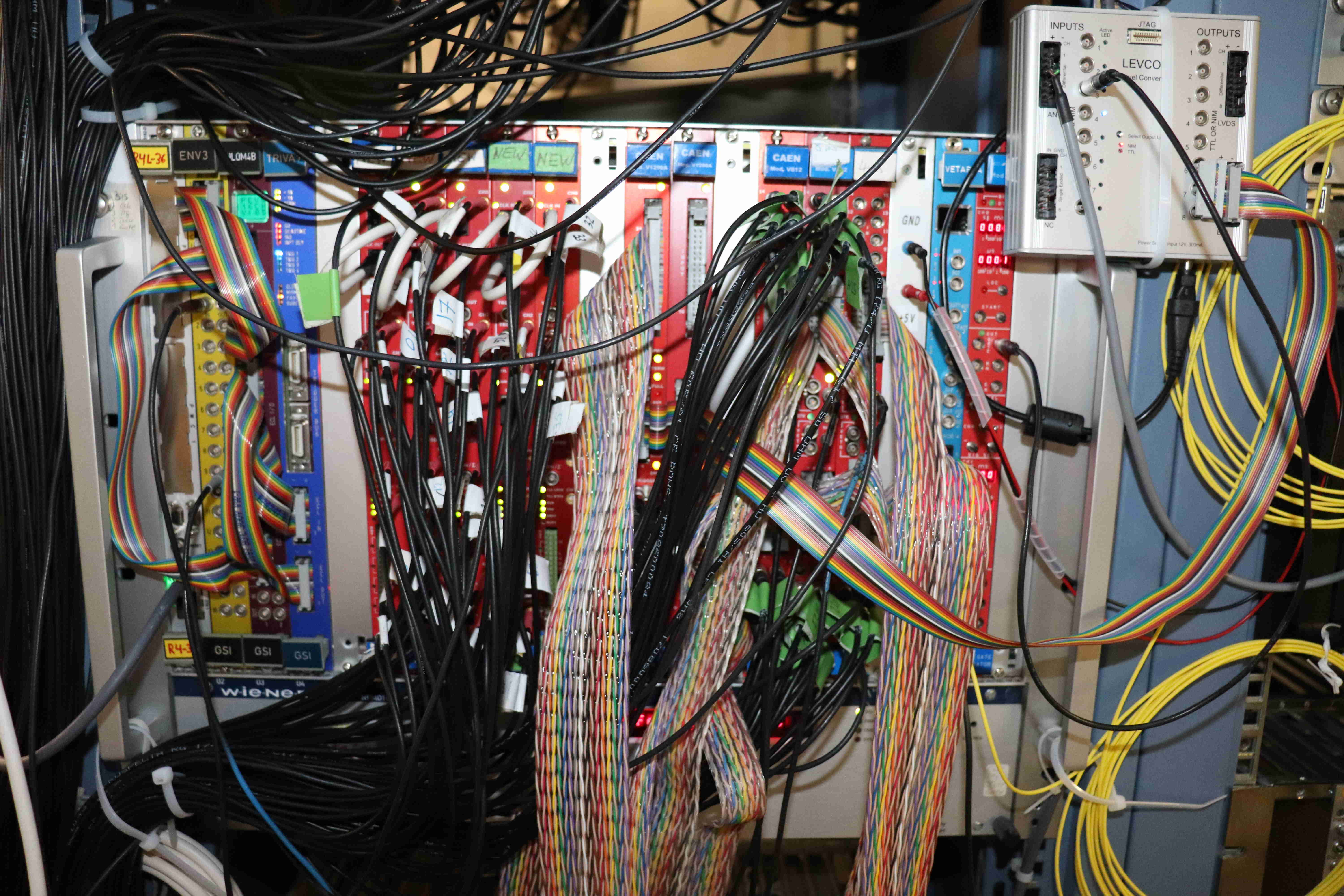
Attachment 8 - FATIMA DAQ

Attachment 9 - DESPEC 19" racks on detector platform |
| Attachment 1: xIMG_1652.JPG
|
|
| Attachment 2: xIMG_1653.JPG
|
|
| Attachment 3: xIMG_1659.JPG
|
|
| Attachment 4: xIMG_1660.JPG
|
|
| Attachment 5: xIMG_1663.JPG
|

|
| Attachment 6: xIMG_1664.JPG
|
|
| Attachment 7: xIMG_1665.JPG
|
|
| Attachment 8: xIMG_1666.JPG
|
|
| Attachment 9: xIMG_1667.JPG
|

|
|
|
490
|
Wed Jun 22 10:09:12 2022 |
PJCS | INFO: FEE64 supply Voltages |
Study of the FEE64 power supply distribution has yielded the following :-
The most sensitive regulator, as regards the device voltage input, is the TPS51100 that supplies the DDR memory reference voltages. This requires +4.75 to +5.25 volts. This is supplied from the Power input connector +5v input.
The common LT3080 regulator used over much of the board is a Low Voltage Dropout regulator. This requires 0.5v difference between input and output voltage as minimum. This is not a problem with the +4.75v minimum for the TPS51100 requirement setting the voltage for the board.
The supply to the mezzanine is direct from the power connector +5v input. On the mezzanine there is an LT3080 for each ASIC supplying the required 3.3v. These regulators would possibly benefit from a 1uF capacitor at the Control voltage input.
The simplest approach would be to add a capacitor to the bottom layer where the Control voltage enters the mezzanine.
The power cable has a nominal resistance of 13.3ohms/km. The 3 conductors of the cable are supplying 10A when all is in operation. So the expected voltage drop would thus be ( 10 x 13.3 x 0.007 ) /3 => 0.3v each core.
The conclusion would be that the voltage at the power supply should drop to 5.25 v thus ensuring the TPS51100 is supplied as required regardless of the operation of the FEE.
This will be tested at Daresbury. |
|
|
514
|
Wed Sep 14 19:07:07 2022 |
PJCS | INFO : Three Merger Statistics explained |
There are three Merger statistics that can be used to better understand how the data flow through the Merger system is proceeding.
Two are from the Link task and one is from the Merger.They are all "No data buffers avaliable" with #1, #2, #3 at the end.
#1: This is incremented when the Link task has a data item to put in the queue for the Merge process but there is no room.
#2: This is incremented when the Link task has found no room in the queue for the Merge process ( #1 ) , waited , tried again and failed.
#3: This the other end of the queue. When the Merge task requests a data item from a Link task queue and there is nothing available.
|
|
|
300
|
Fri May 7 19:47:54 2021 |
PJCS | HowTo mitigate excessive temperature in an FEE64 |
After tests in the Daresbury T9 system.
Disabling the waveform ADCs in an FEE64 which is running with the FPGA over temperature will drop the FPGA temperature by 10 degrees.
To disable the ADCs open the Local Control browser window and set the ADC Control register , @2, to 0xFF
The easiest way to restart the waveform ADCs correctly is to rerun SETUP from the control window selecting just the FEE that is affected.
Alternatively STOP acquisition, set the ADC Control register back to 0 and rerun the calibrate ADCs in the FADC Align and Control browser window.
|
|
|
52
|
Mon May 20 13:51:45 2019 |
NH | HowTo Verify WR Times |
The latest version of MIDAS has a new page to check the WR timestamp of each FEE.
In AIDA Hardware control click: GSI White Rabbit Control
In expert options click: Collect all Timestamps
Verify every FEE has a good timestamp. |
| Attachment 1: HowTo-WR1.png
|

|
| Attachment 2: HowTo-WR2.png
|

|
| Attachment 3: HowTo-WR3.png
|

|
|
|
211
|
Wed Mar 31 15:46:09 2021 |
PJCS | HowTo : Synchronize the ASIC clocks. |
To Synchronize the FEE64 ASIC clocks to rise at the same timestamp time use the System function Synchronise the ASIC clocks in the System Wide Checks browser page.
The Server will read the current timestamp value and calculate, based on the number of FEEs and the access delay, a timestamp value sometime in the future. F_stamp
F_stamp is written to each FEE and the synchronization is enabled.
In a state machine in the FEE ASIC clock control, logic is enabled to synchronize its ASIC clock. It compares the current timestamp with F_stamp and if the current timestamp is >= F_stamp then it will start the ASIC clock.
The report in the browser log window gives the 3 LSBs of the timestamp at the instant the ASIC clock is started. They should all be the same. They are from the 10ns timestamp.
|
|
|
209
|
Wed Mar 31 12:46:10 2021 |
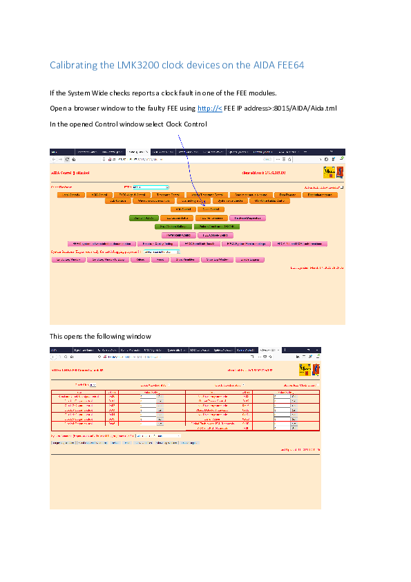
PJCS | HowTo : Calibrate the LMK3200 clock devices |
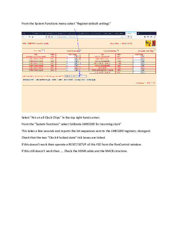
Here is a document showing how and where to calibrate the LMK3200 devices that lock to the system clock and generate the clocks for the ADCs and the FPGA internal logic. |
| Attachment 1: Calibrating_the_LMK3200_clock_devices_on_the_AIDA_FEE64.pdf
|
|
|
|
36
|
Tue Mar 26 14:58:09 2019 |
NH, VP | How to reset merger |
If the merger doesn't show "xfer Links => Merger" at the top, it is probably the merger setting has been corrupted somehow. This is how to reset it
If you go to the web page from which you started the Merge and TapeServer
(probably localhost:8115)
Then select the item NetVar Service which is at the left hand end.
Click on Inquire Registers
then enter NetVar.MERGE.RunOptions into the "Register Name" entry and when finished move the mouse out of the entry box.
NetVar.MERGE.RunOptions will appear in the center of the top row. (it is an item in the menu but not so easy to find)
Click on Read and I expect you will get 0
Type 1 into the data entry box and click on Write
Now return to the Merger and click on Reload
The Merger State will now end as xfer Links => Merger
The button Output: will now toggle between this and xfer links => Merger => Storage. |
|
|
63
|
Wed Aug 14 14:40:18 2019 |
NH | High Frequency Noise in AIDA |
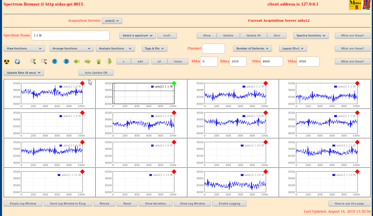
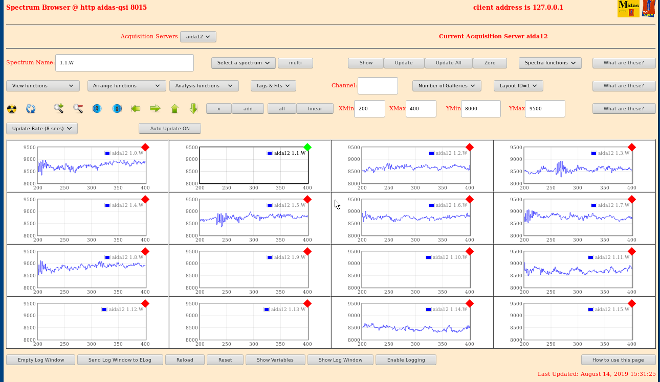
Figures of intense high frequency noise pickup in AIDA.
Will investigate source in S4.
Edit: Period is approx 40 cycles / approx 2.5 MHz (?) |
| Attachment 1: HF.png
|
|
| Attachment 2: HFZ.png
|
|
|
|
133
|
Tue Feb 25 09:55:59 2020 |
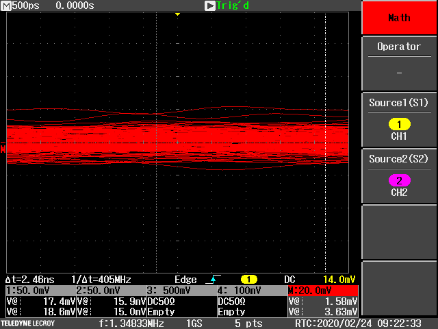
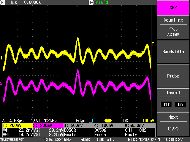
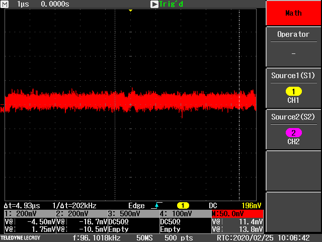
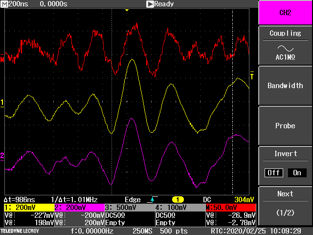
NH | HV Scope Traces |
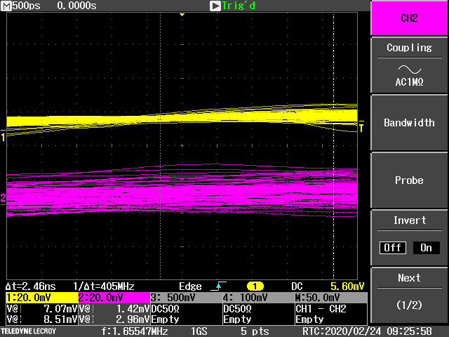
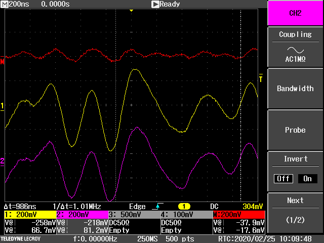
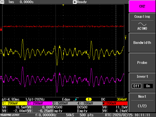
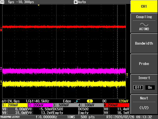
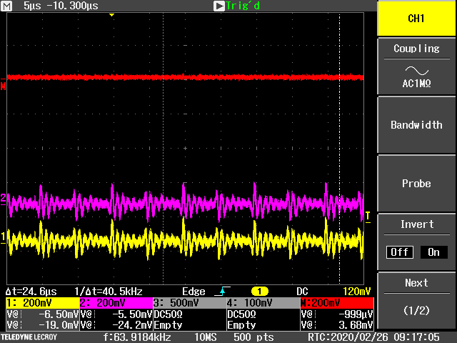
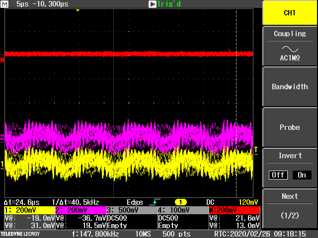
Looking at the HV bias in a scope to see if it is the source of noise especially on the p+n side

Channel 1: HV Core channel 4
Channel 2: HV Braid Channel 4
Math: Ch1 - Ch2

100V bias (100 uA leakage current for 1 MOhm)

No obvious frequency components or large frequency components?
I do not know how this compares to RIKEN or STFC-DL

Updated to put the right frequency range (misread before)

Fig 3-4: Normalish looking data

Fig 5-6: Examples of noise appearing randomly on math line

Fig 7: 1ms long trace, noise stopped appearing

Update 26.02.2020

Fig 8: Trace with all 4 HV channels off

Fig 9: Trace with only oscilloscope biased

Fig 10: Trace with braids unplugged from all 3 FEE64s (only channel 4 connected)

Things to try:

Joining clean earth & chassis ground?

Checking HV jumper?

Finding 'scope probes and testing NIM socket? |
| Attachment 1: SCRN0057.PNG
|
|
| Attachment 2: SCRN0054.PNG
|
|
| Attachment 3: SCRN0059.PNG
|
|
| Attachment 4: SCRN0060.PNG
|
|
| Attachment 5: SCRN0071.PNG
|
|
| Attachment 6: SCRN0073.PNG
|
|
| Attachment 7: SCRN0075.PNG
|
|
| Attachment 8: SCRN0078.PNG
|
|
| Attachment 9: SCRN0079.PNG
|
|
| Attachment 10: SCRN0080.PNG
|
|
|
|
672
|
Wed Dec 4 09:57:24 2024 |
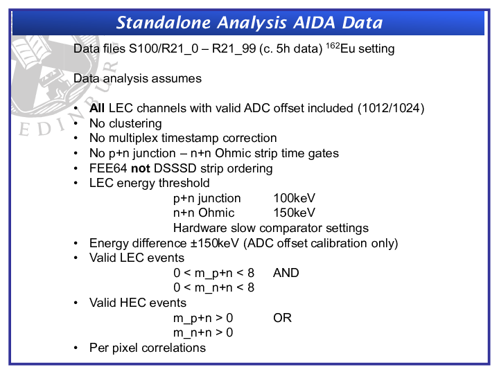
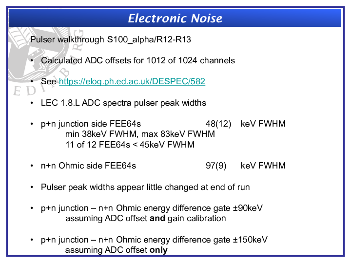
TD | HISPEC DESPEC meeting presentation - November 2024 -0 Summary of AIDA performance 2024 |
|
| Attachment 1: Summary_of_AIDA_2024_distro.pdf
|

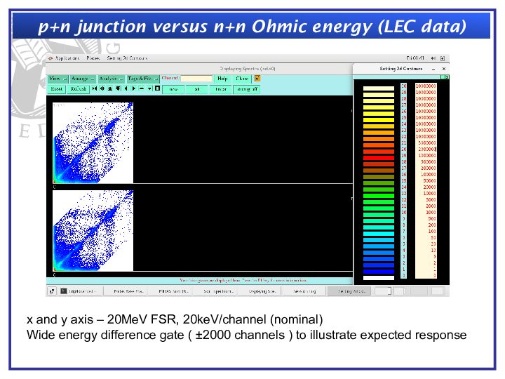
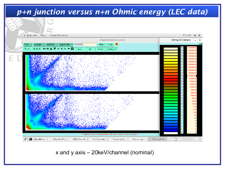
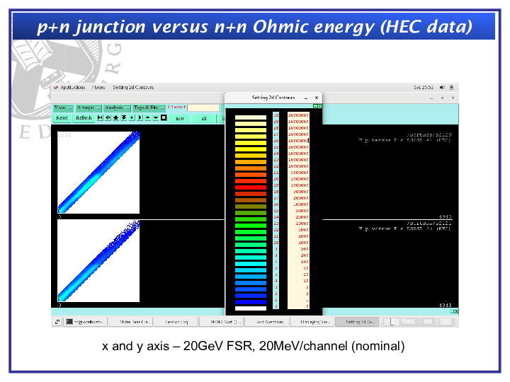
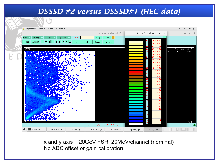
|
|
|
403
|
Sat Mar 5 10:43:45 2022 |
OH, NH | Grounding and noise tests 4th-5th March Summary |
Tests performed
- After leaving overnight noticed the pulser was not fully inserted into aida09
- Little change in rates observed in 9 but otherwise nothing else
- Connected bias of aida02 (n+n ground) to aida06 (n+n ground) and likewise 4-8
- No change observed in rates
- Also tested covering the snout in light tight material
- Unplugged the system monitor from 6 and 8, no change
- Connected the snout to ground with copper tape
- Rates became very unpredictable in the FEEs unsure if this was snout grounding related though
- Removed the ground and powercycled and rates restored to where previously
- Changed the bias supply jumper inside to have the bias line connected to the rack ground
- At the same time noticed that the ground cable connecting the adaptor board of aida06 to the FEE had become disconnected from the ring terminal
- Recrimped and inserted again
- Saw an improvment in the rates of the p+n strips and also the n+n strips - attachment 1
- Pulser widths however larger than yesterday
p+n width
| FEE |
Width |
| 9 |
118 |
| 1 |
88 |
| 10 |
75 |
| 11 |
77 |
| 3 |
67 |
| 12 |
66 |
| 13 |
96 |
| 5 |
89 |
| 14 |
107 |
| 15 |
93 |
| 7 |
118 |
| 16 |
87 |
n+n width
- Connected up entire pulser circuit to n+n FEEs
| FEE |
Width |
| 2 |
428 |
| 4 |
N/A |
| 6 |
428 |
| 8 |
343 |
Switching bias supply back
- because changes were made to the n+n ground, and the pulser circuit it was decided to go back and check the previous bias configuration with the module set in a floating configuration
- DAQ was then left overnight as had to leave to catch the bus
- Rates are observed to be back at their higher values - attachment 2
- n+n 1.8.L spectra - attachment 3
- p+n 1.8.L spectra - attachment 4
p+n widths
| FEE |
Wdith |
| 9 |
130 |
| 1 |
128 |
| 10 |
75 |
| 11 |
78 |
| 3 |
71 |
| 12 |
71 |
| 13 |
96 |
| 5 |
85 |
| 14 |
110 |
| 15 |
99 |
| 7 |
123 Dbl |
| 16 |
92 |
n+n widths
| FEE |
width |
| 2 |
56 |
| 4 |
983 |
| 6 |
523 |
| 8 |
358 |
- The results show no improvment to slightly worse performance so will go back to having the bias module grounded internally and check the previous conclusions hold before making further changes
Return to grounded bias module
Widths
p+n
| FEE |
Width |
| 9 |
106 |
| 1 |
79 |
| 10 |
72 |
| 11 |
78 |
| 3 |
70 |
| 12 |
73 |
| 13 |
102 |
| 5 |
112 |
| 14 |
105 |
| 15 |
110 |
| 7 |
131 |
| 16 |
104 |
n+n
| FEE |
Width |
| 2 |
- |
| 4 |
298 |
| 6- |
- |
| 8 |
278 |
- Don't see a pulser peak in 4 or 2
- Will replace cable between 4 and 2 and 2 and 6
- Statistics at 0x64 with pulser on - atachment 5
- Now see peaks - attachment 6
- Statistics at 0xa - attachment 7
| FEE |
Width |
| 2 |
284 |
| 4 |
1089 (Triple) |
| 6 |
371 |
| 8 |
318 |
With the grounded bias in place in the module move the braid cable to the frame rather than being connected to bias line
- Still observe a triple peak in 4 and have worse perfromance in 2 and no improvement in p+n
- 0x64 stats - attachment 7
- 0xa statistics - attachment 8
- p+n 1.8.L - attachment 9
- p+n waveform - attachment 10
- n+n waveform - attachment 11
- Same high frequency component in both
- 35 channel spacing corresponds to a frequency of ~1.4MHz
| FEE p+n |
Width |
| 9 |
109 |
| 1 |
118 |
| 10 |
78 |
| 11 |
80 |
| 3 |
70 |
| 12 |
73 |
| 13 |
92 |
| 5 |
85 |
| 14 |
99 |
| 15 |
100 |
| 7 |
123 |
| 16 |
92 |
| FEE n+n |
Width |
| 2 |
531 |
| 4 |
1185 (Triple) |
| 6 |
536 |
| 8 |
376 |
Next tests
- Returned braid to FEE 4 and 8
- Recovered earlier rates and performance
- Re-added the ground cable to the snout
- Much worse noise performance across all FEEs
- p+n rates in 200k
- Removed the ground from the snout
- Got really good rates originally - attachment 12
- Noticed 1 and 5 failed ADC calibration
- Calibrated them and there rates increased massively - attachment 13
- Notice that the pulser peak in FEE2 and 6 keeps dropping out
- As the cables have been changed multiple times thought it could be that an adaptor board was broken
- 4 seemed the most likely suspect with its high rates and triple peaks
- Replaced the adaptor board with one missing an outer ERNI pin (PIN doesn't interface with the FEE so didn't see any issues)
- Pulser peaks were still muissing
- Issue could be then with adaptor board 2 possibly
Conclusions
- Rates on the FEEs are in a better place now than they were at the start of the week
- p+n in particular have shown a large amount of improvement
- There are still however issues with the n+n FEEs
- I think there is likely an issue with one of the adaptor boards
- Possible aida02 at the pulser connection point
- Could explain the triple peaking in aida04 and the pulser issues with aida02 and aida06 dropping out.
- Would recomend swapping out aida02 as a test next week
- Other possible issues coiuld be the clingfilm around the cables has torn and we are grounding the cables to the inside of the snout
- Nic would like to use something other than clingfilm in future
- One suggestion would be mylar which could be held in place with strips of double sided tape
- This would make the cables less likely to stick to each other which is an issue with the tightness of the snout
- Could also try removing LK3 from FEE3 and 7 leaving the PCB ground floating
- I am at a slight loss of what else to try
- I have left the daq running at 0x64 overnight to check for alphas
- Histograms and statistics zeroed
|
| Attachment 1: 220304_1704_groundedbias_stats.png
|

|
| Attachment 2: 220305_1154_Stats.png
|

|
| Attachment 3: 220305_1157_nn_18L.png
|

|
| Attachment 4: 220305_1200_pn_18L.png
|

|
| Attachment 5: 220305_1336_0x64Stats.png
|

|
| Attachment 6: 220305_1341_nn_18L.png
|

|
| Attachment 7: 220305_1342_Stats.png
|

|
| Attachment 8: 220305_1405_0x64_stats.png
|

|
| Attachment 9: 220305_1421_pn_18L.png
|

|
| Attachment 10: 220305_1424_pn_waveform.png
|

|
| Attachment 11: 220305_1429_nn_waveform.png
|

|
| Attachment 12: 220305_1518_stats.png
|

|
| Attachment 13: 220305_1519_waveform_enabled.png
|

|
|
|
392
|
Fri Oct 29 23:00:04 2021 |
NH | Ground cable information |
For future refinement of the AIDA ground cables using copper bus bar or similar:

Thin cable (from AIDA FEEs to common connection point)
- AWG14 grn/ylw ground cable
- M6 screw crimp?

Thick cable (from common point to mechanical ground)
- AWG4 (25mm2) grn/ylw ground cable
- M12 bolt to mechanical frame |
|
|
729
|
Tue Oct 28 12:43:38 2025 |
JB, GB, MP, AM | Further setup of tests for 207Bi test |
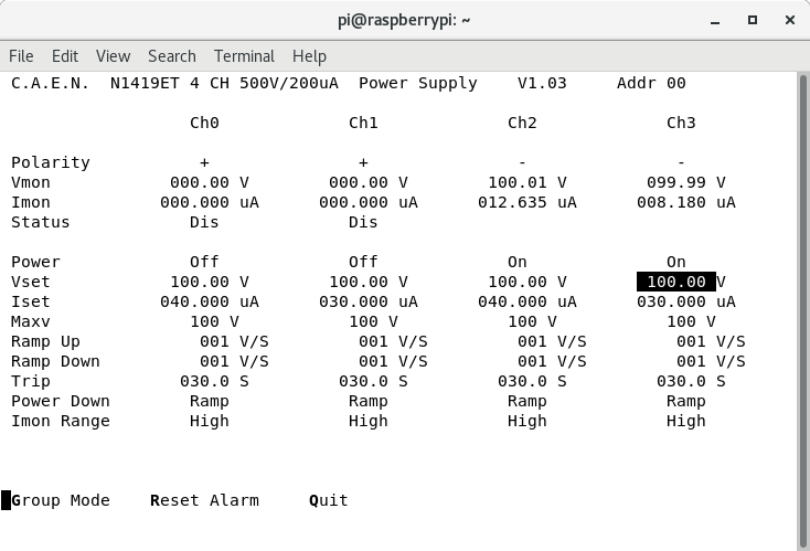
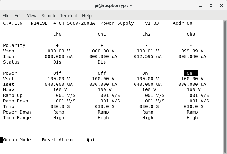
- Ch 2 and 3 of CAEN HV module changed to negative polarity, Ch 0,1 still with positive polarity
- Bias changed from the n+n to the p+n side (now Ch 2,3) - att. 1

- EXPERIMENTS/AIDA/2025Oct28-14.55.15 -> Slow comparitor -> 0x64 (1MeV) p+n Pos. bias & n+n Neg. bias

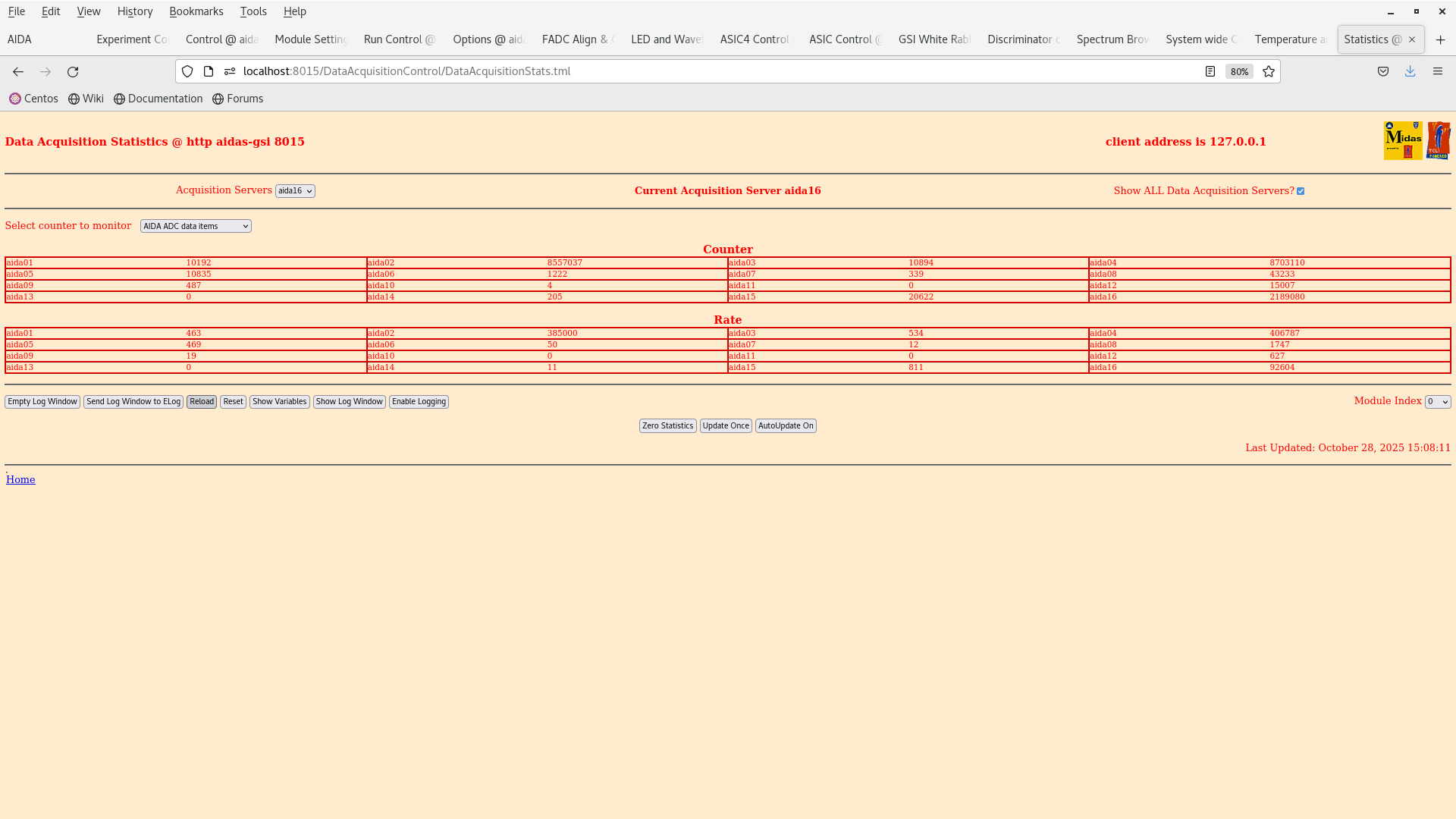
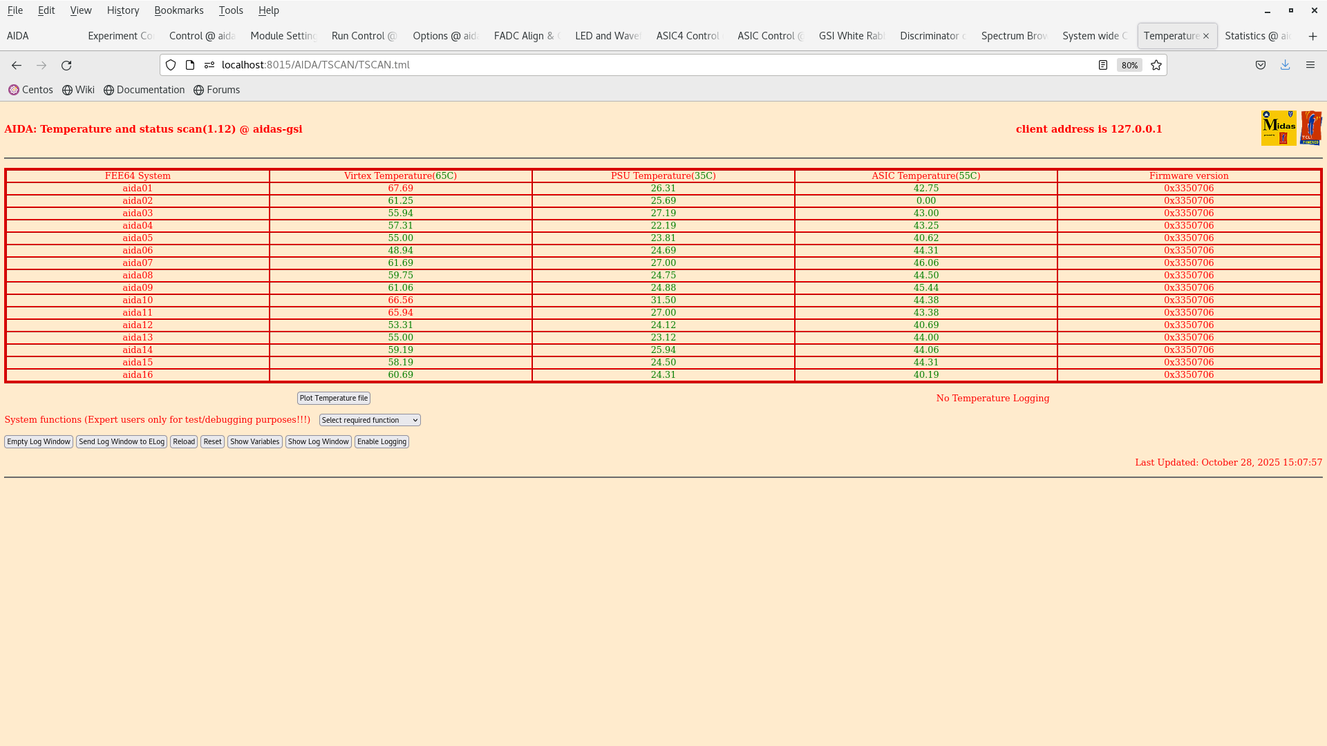
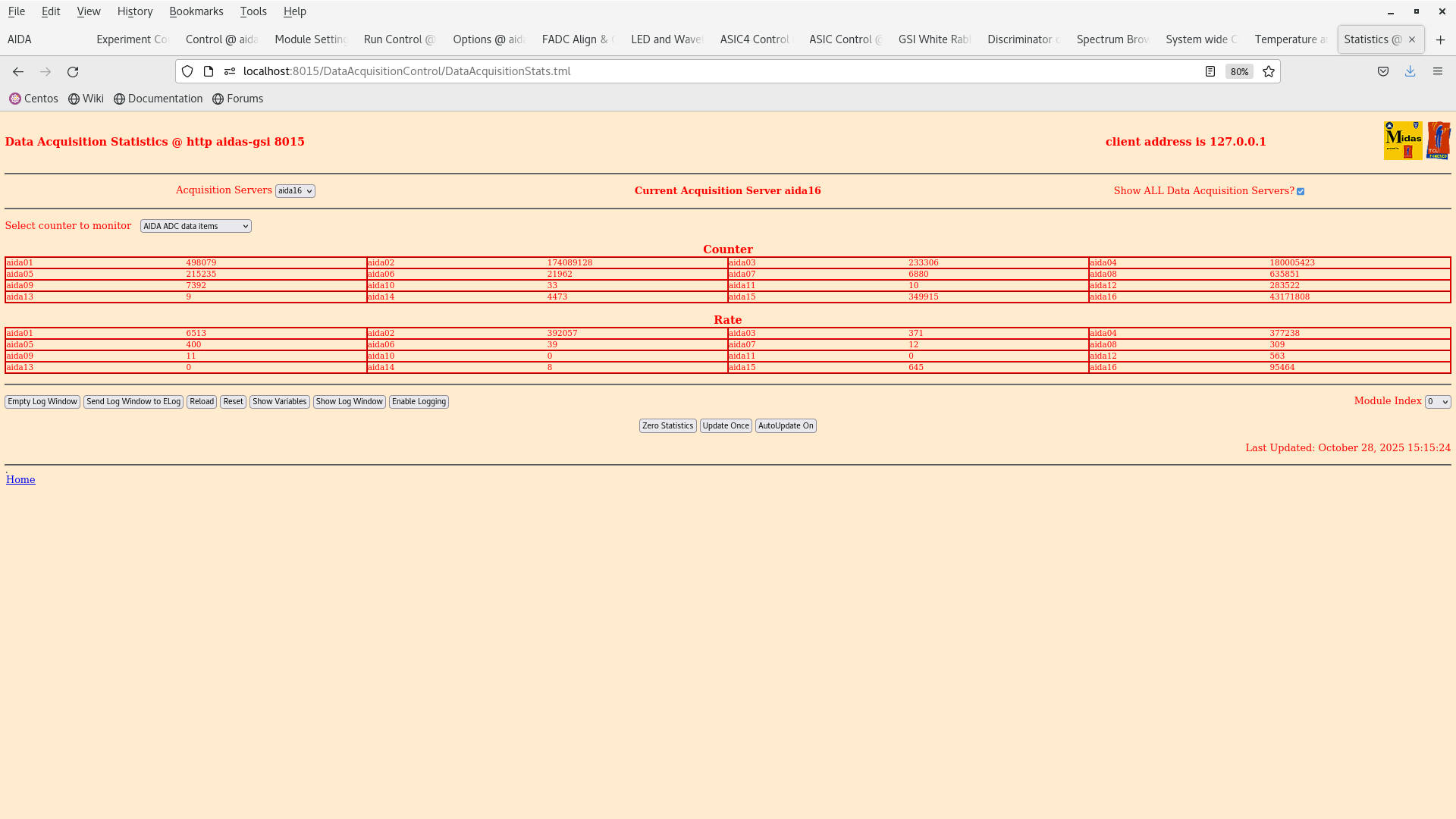
- Attachment 7: aida01 had its threshold lowered to 500 keV -> Rate increased from 500 to 6500 Hz
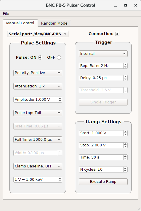
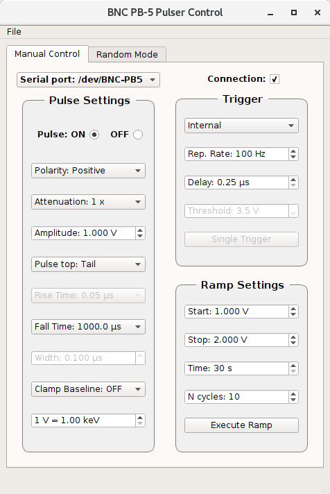
- Pulser inputs plugged in.


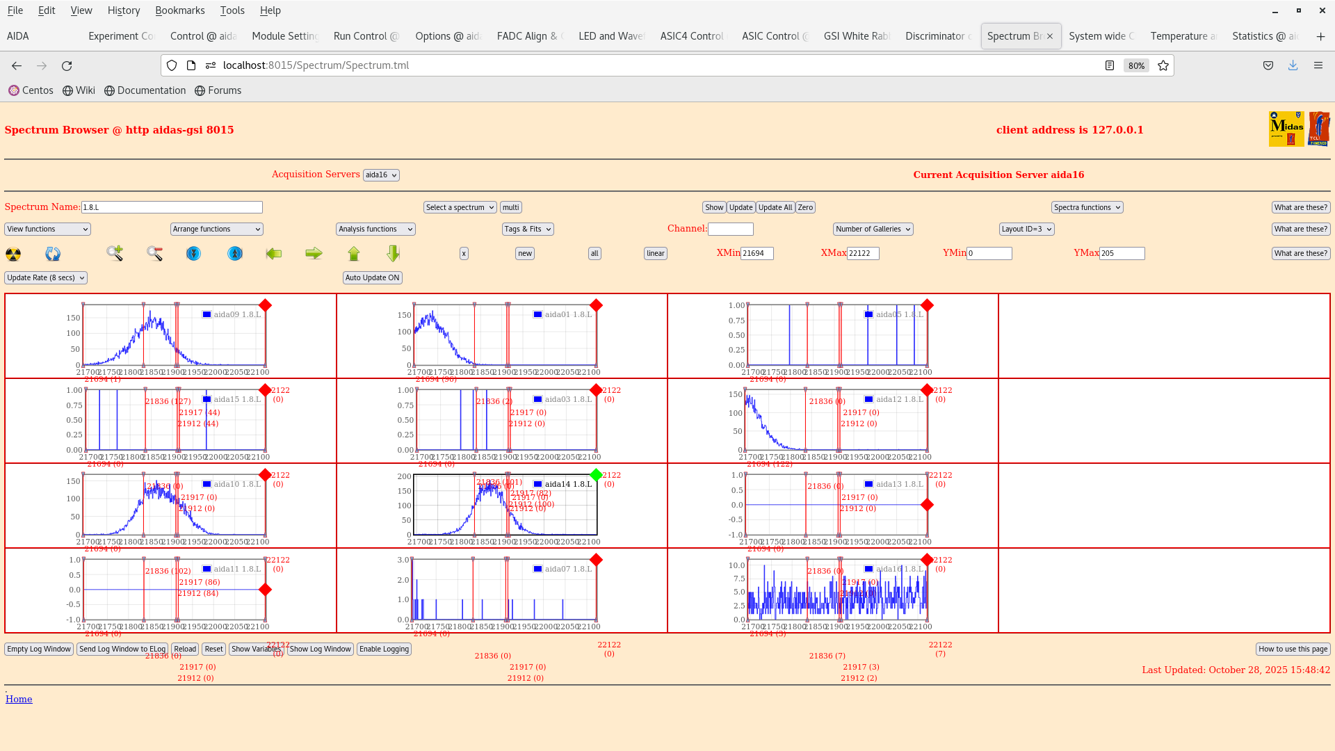
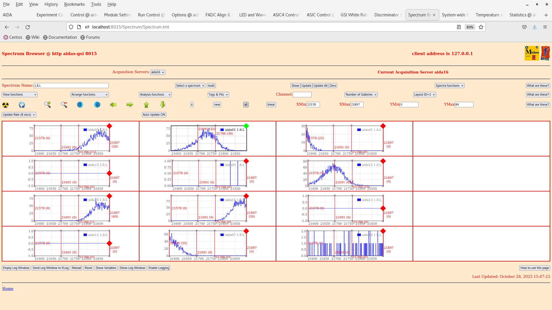
We have input a 1V pulser input into the data and have measured a peak in aida01 with a FWHM = 75 channel see attachment 9 and a FWHM in aida 14 (DSSD2) of also 76 channels which is similar to the results obtained in June from Nabil.


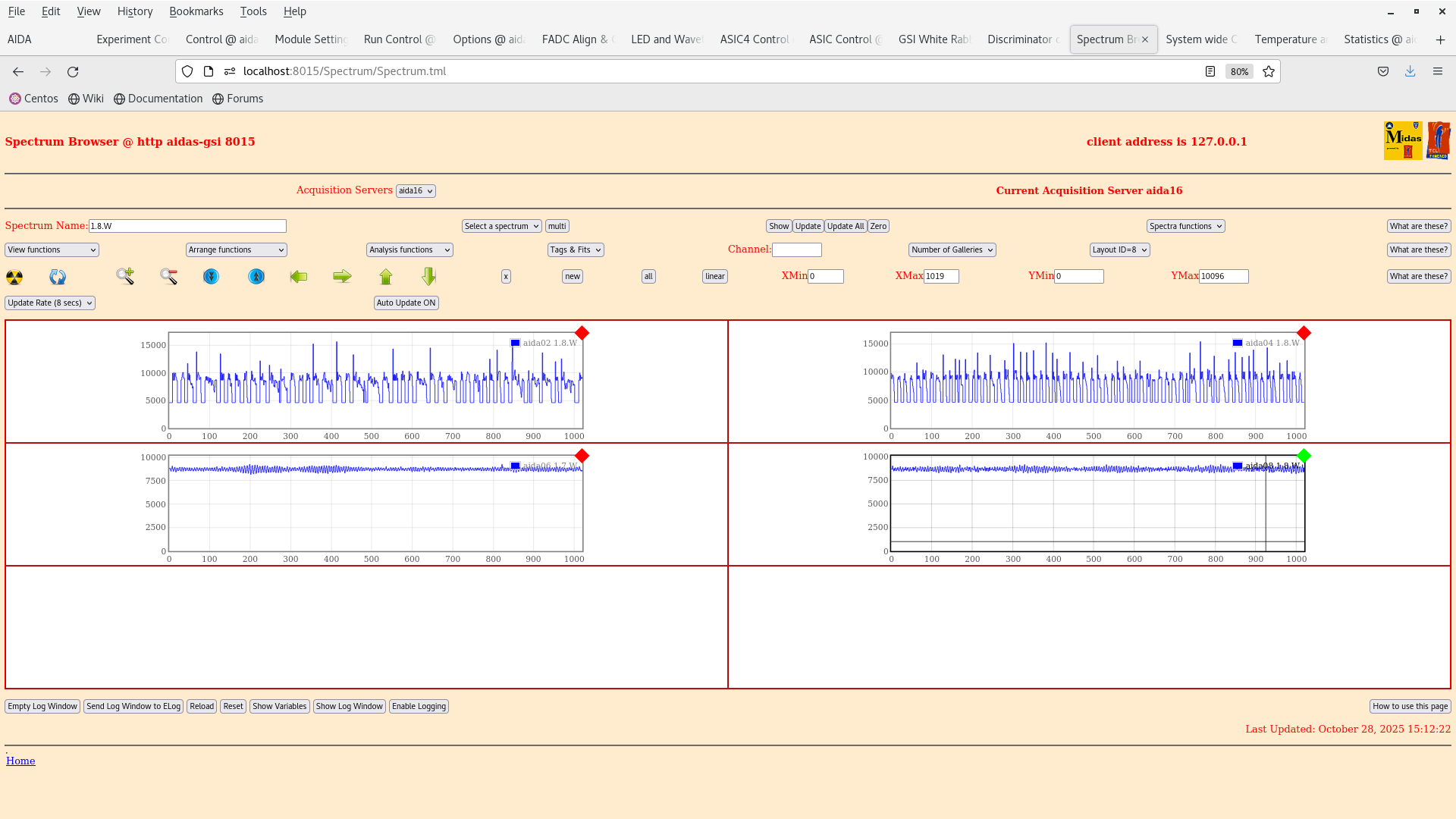
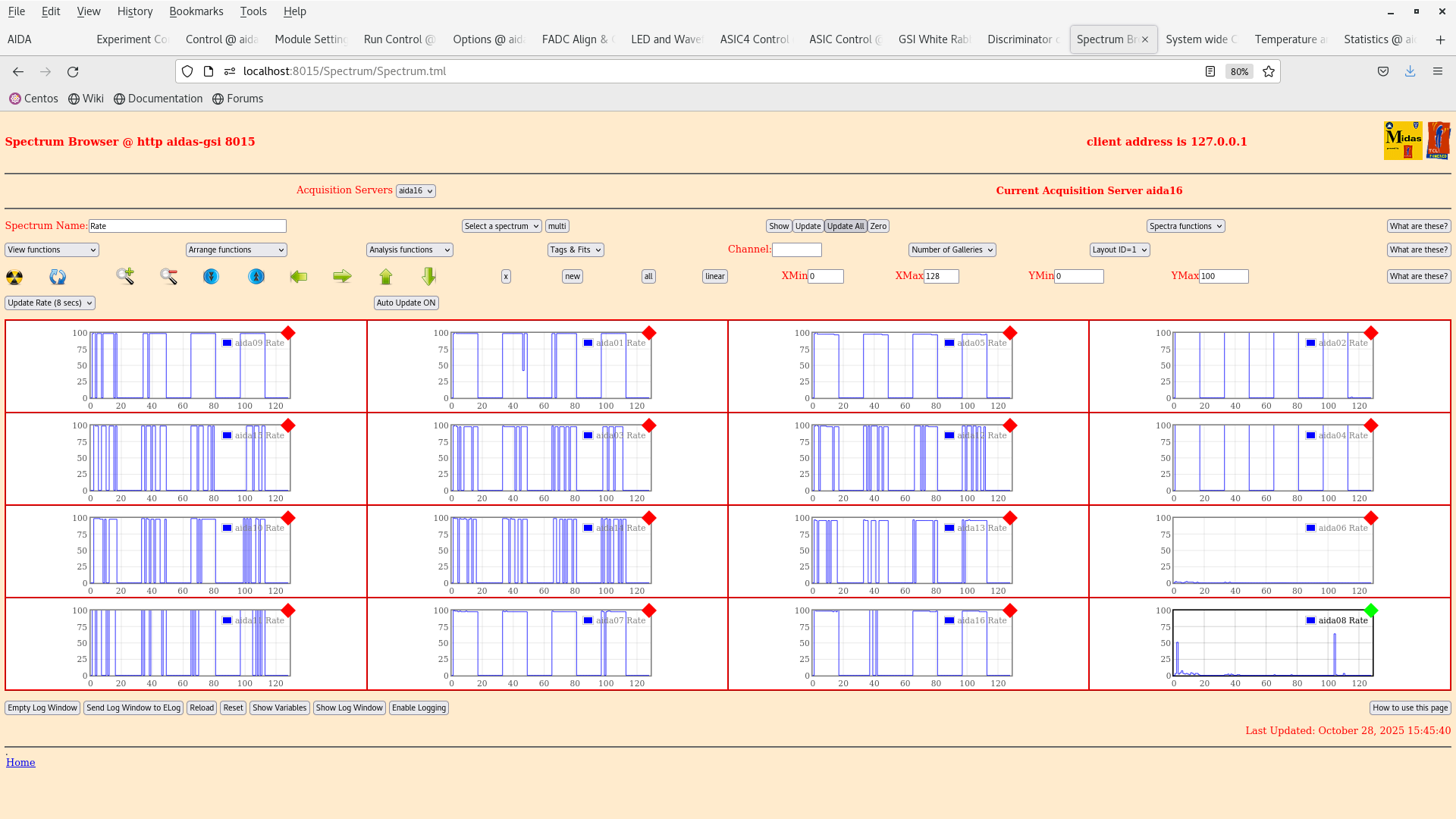
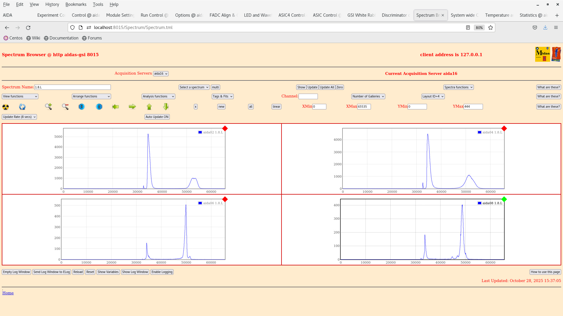
We cannot see anything from the n+n side as the signals are too noisy. Probably best to go with a higher trigger rate on the pulser and check with log scale tomorrow. It might also be worth checking the grounding on the y-strips as the problem with biasing with positive polarity is still seen in aida02 and aida04 (high noise repetition0 signal, attachment 2).

Conclusion is that we have reproduced in part the result from Nabil.

Tomorrow we will continue with the tests by lowering the thresholds and hopefully collect some data :-) |
| Attachment 1: Screenshot_from_2025-10-28_14-28-30.png
|
|
| Attachment 2: Screenshot_from_2025-10-28_15-12-27.png
|
|
| Attachment 3: Screenshot_from_2025-10-28_15-10-42.png
|
|
| Attachment 4: Screenshot_from_2025-10-28_15-09-59.png
|
|
| Attachment 5: Screenshot_from_2025-10-28_15-08-24.png
|
|
| Attachment 6: Screenshot_from_2025-10-28_15-08-02.png
|
|
| Attachment 7: Screenshot_from_2025-10-28_15-15-31.png
|
|
| Attachment 8: Screenshot_from_2025-10-28_15-49-20.png
|
|
| Attachment 9: Screenshot_from_2025-10-28_15-47-44.png
|
|
| Attachment 10: Screenshot_from_2025-10-28_15-45-44.png
|
|
| Attachment 11: Screenshot_from_2025-10-28_15-37-13.png
|
|
| Attachment 12: Screenshot_from_2025-10-28_15-31-20.png
|
|
| Attachment 13: Screenshot_from_2025-10-28_15-50-19.png
|
|
| Attachment 14: AIDA_scheme_241020525(1).png
|
.png.png)
|
|
|
730
|
Wed Oct 29 08:12:35 2025 |
MP | Further setup for 207Bi test |
Inspection of side FEEs (2,6,4,8) and possible grounding improvements:
- all screws and nuts for copper connections were tightenedFee
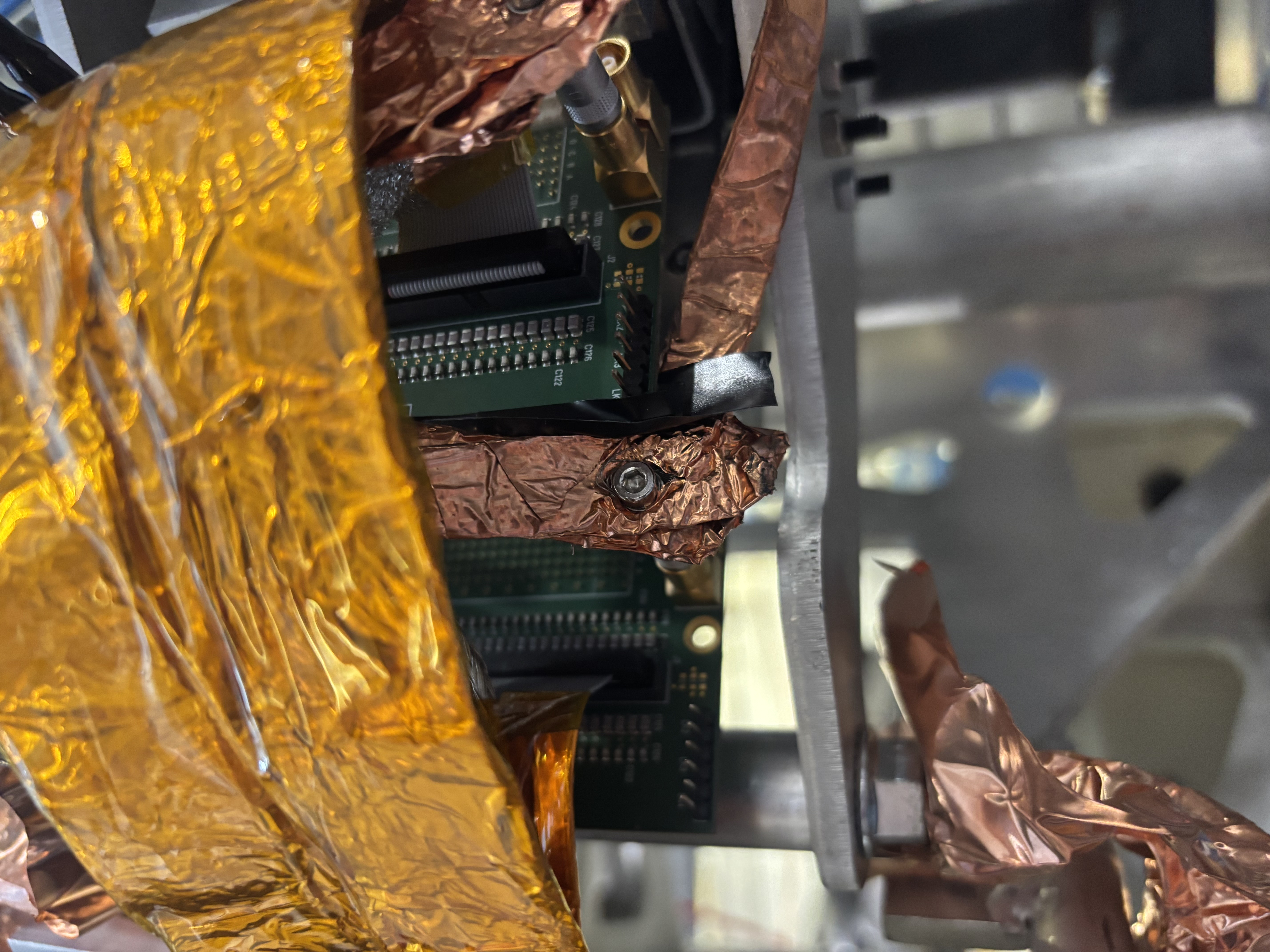
- FEE 6 was isolated from the copper connection grounding FEE2 with insulating tape (attachment 1)
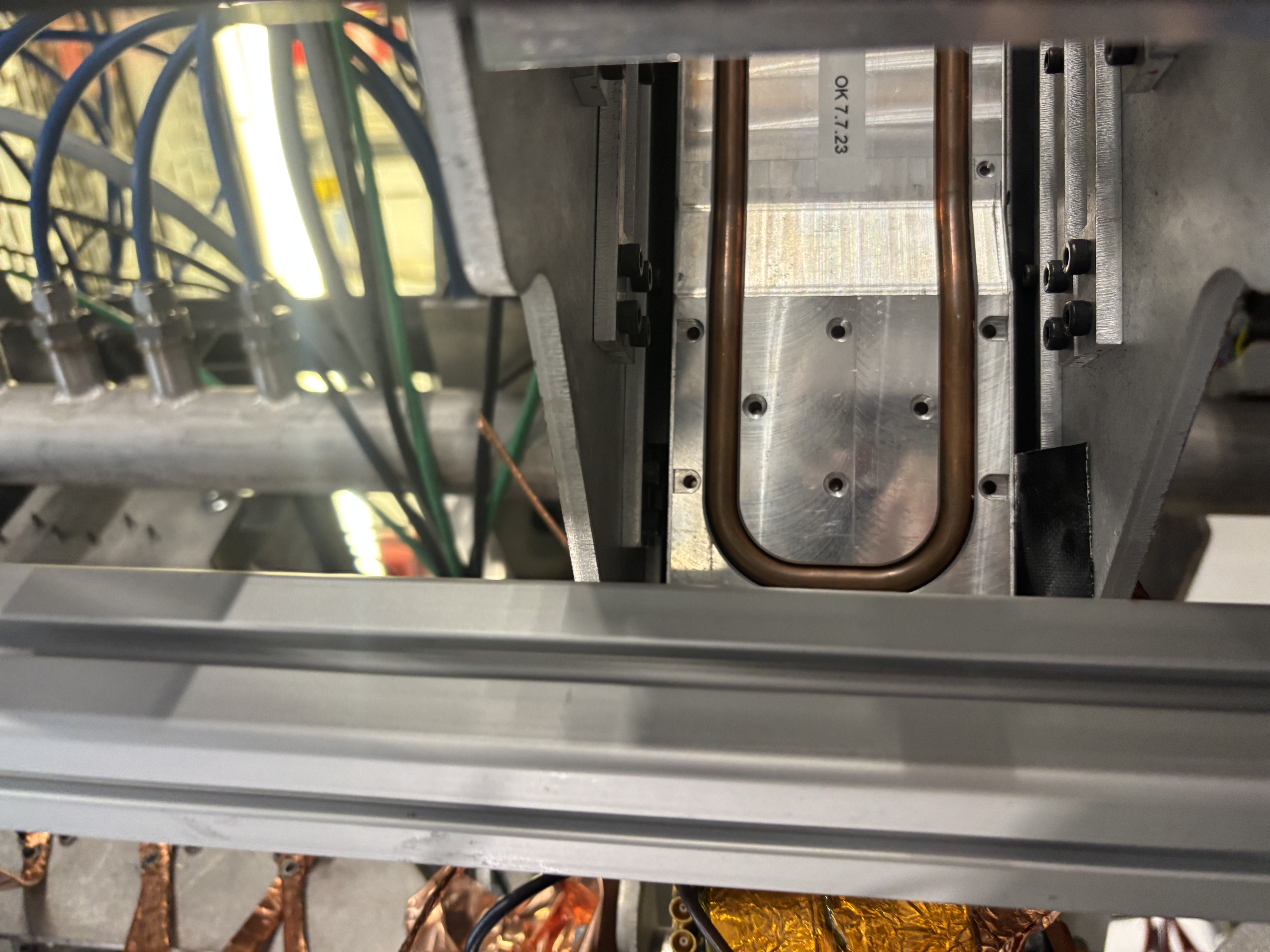
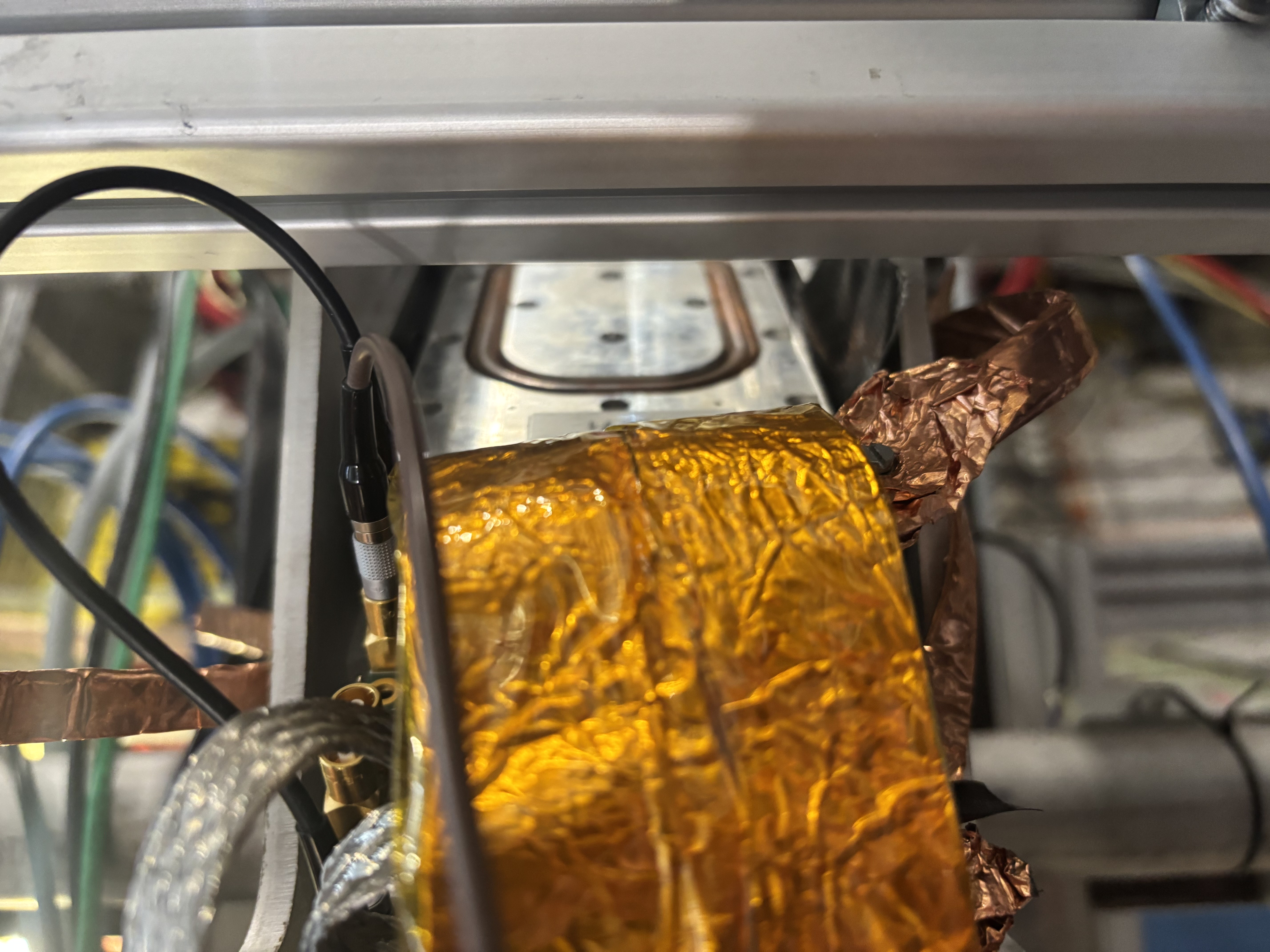
- A piece of tape was found below FEE6 (attachments 2,3) --> shall this be removed?
Bias and power on of FEES, preparation of two settings with lower thresholds:
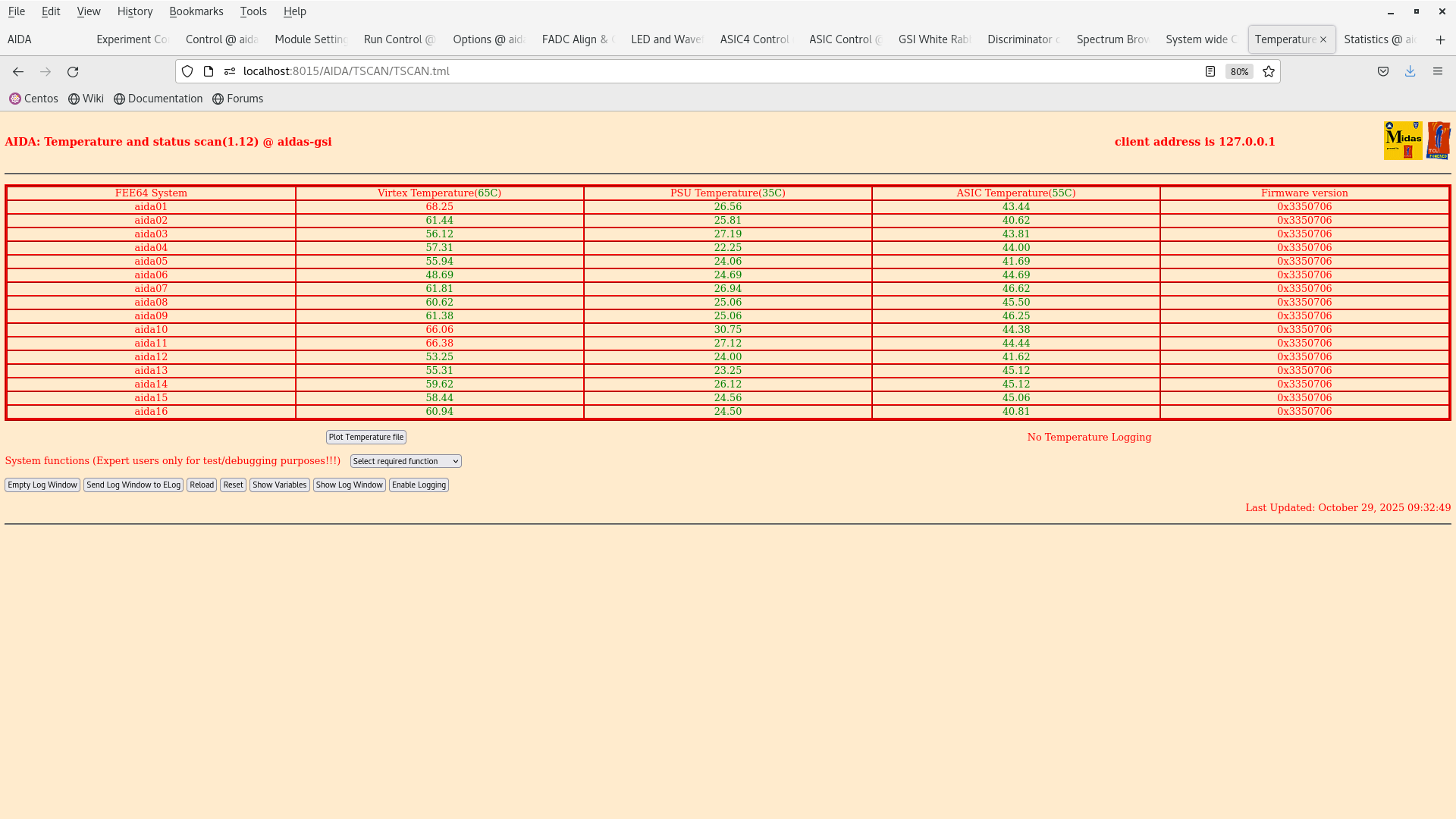
- note: cannot calibrate ADC of aida15 even after trying multiple times (?)
- 500-keV thresholds settings saved as EXPERIMENTS/AIDA/2025Oct29-09.49.01
- 200-keV thresholds settings saved as EXPERIMENTS/AIDA/2025Oct29-09.55.31
|
| Attachment 1: IMG_5959.jpeg
|
|
| Attachment 2: IMG_5958.jpeg
|
|
| Attachment 3: IMG_5957.jpeg
|
|
| Attachment 4: Screenshot_from_2025-10-29_09-23-32.png
|
|
| Attachment 5: Screenshot_from_2025-10-29_09-32-52.png
|
|
|
|
731
|
Wed Oct 29 12:56:29 2025 |
TD | Further setup for 207Bi test |
Remember that 'ADC calibration' refers to the setup of the fast serial output of the AD9222 Octal, 50MSPS, 14 bit ADC which generates the waveforms - if the FEE64 is unable to calibrate all that happens is that you will not be able to see preamp output waveforms. Energy spectra will work regardless as they use a different ADC.
| Quote: |
|
Inspection of side FEEs (2,6,4,8) and possible grounding improvements:
- all screws and nuts for copper connections were tightenedFee
- FEE 6 was isolated from the copper connection grounding FEE2 with insulating tape (attachment 1)
- A piece of tape was found below FEE6 (attachments 2,3) --> shall this be removed?
Bias and power on of FEES, preparation of two settings with lower thresholds:
- note: cannot calibrate ADC of aida15 even after trying multiple times (?)
- 500-keV thresholds settings saved as EXPERIMENTS/AIDA/2025Oct29-09.49.01
- 200-keV thresholds settings saved as EXPERIMENTS/AIDA/2025Oct29-09.55.31
|
|
|
|
171
|
Thu Mar 4 11:16:13 2021 |
OH | Further cases of possible database issues |
During testing for the S452 experiment yesterday we were running through the steps of a restart.

The FEEs were not powercycled at this stage but the MIDAS server was restarted.
Initial setup went smoothly and no issues were encountered during setup.
NewMerger and TapeServer were both setup and set to going.
Upon ''Going'' the run control the data transfer for aida09 dropped out.
Going to the NewMerger it could be seen that data was making it through and data items were being merged.
The tapeserver however was seeing no data and neither was the MBS dataspy.
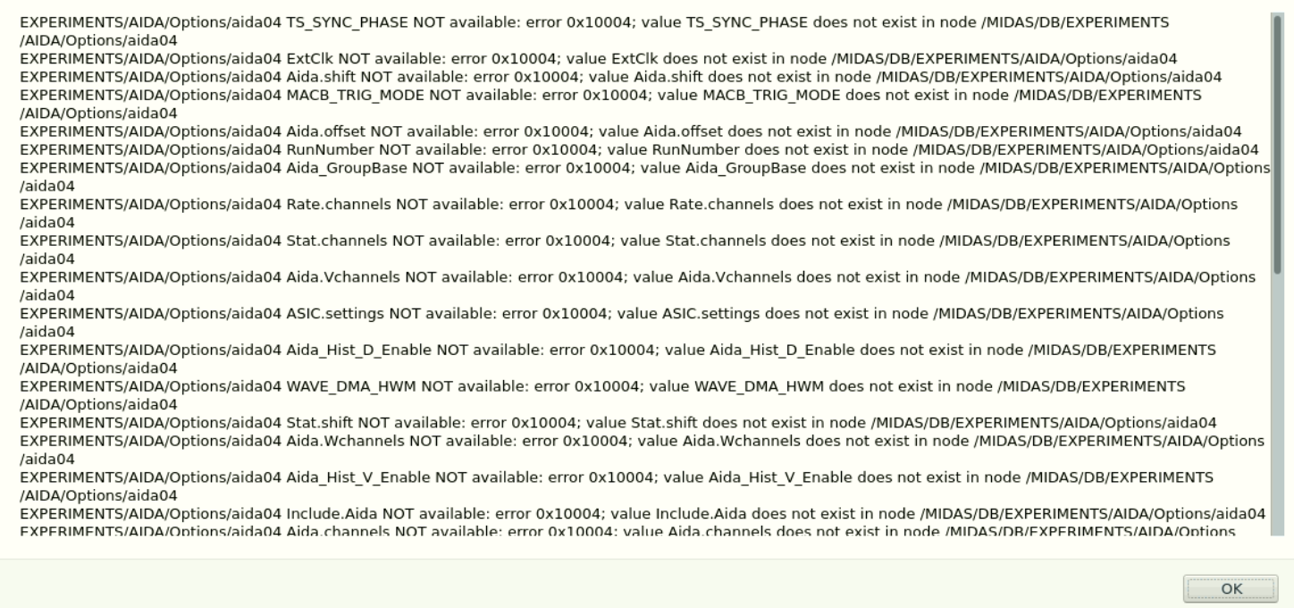
During this time the FEEs became unresponsive likely as their buffers filled. Trying to reset gave the attached errors.

Checking the folder manually it could be seen that the Options file was there.

At this point a powercycle was pewrformed but upong 'Going' the DAQ the same issue was again encountered.

This time we were able to recover control access to the FEEs by running multiple NewMerger sessions which helped clear the buffers.

During our search for the problem we looked at the Options from within MIDAS and could not see anything out of the ordinary.
We also tried restoring the Options from within MIDAS.
We again reached the same issue with the tapeserver.

At this point we restored the Options folder from by copying manually within terminal.
Following this we were able to start the DAQ normally. |
| Attachment 1: ErrorMessage.PNG
|
|
| Attachment 2: errorMessage.txt
|
EXPERIMENTS/AIDA/Options/aida04 TS_SYNC_PHASE NOT available: error 0x10004; value TS_SYNC_PHASE does not exist in node /MIDAS/DB/EXPERIMENTS/AIDA/Options/aida04
EXPERIMENTS/AIDA/Options/aida04 ExtClk NOT available: error 0x10004; value ExtClk does not exist in node /MIDAS/DB/EXPERIMENTS/AIDA/Options/aida04
EXPERIMENTS/AIDA/Options/aida04 Aida.shift NOT available: error 0x10004; value Aida.shift does not exist in node /MIDAS/DB/EXPERIMENTS/AIDA/Options/aida04
EXPERIMENTS/AIDA/Options/aida04 MACB_TRIG_MODE NOT available: error 0x10004; value MACB_TRIG_MODE does not exist in node /MIDAS/DB/EXPERIMENTS/AIDA/Options/aida04
EXPERIMENTS/AIDA/Options/aida04 Aida.offset NOT available: error 0x10004; value Aida.offset does not exist in node /MIDAS/DB/EXPERIMENTS/AIDA/Options/aida04
EXPERIMENTS/AIDA/Options/aida04 RunNumber NOT available: error 0x10004; value RunNumber does not exist in node /MIDAS/DB/EXPERIMENTS/AIDA/Options/aida04
EXPERIMENTS/AIDA/Options/aida04 Aida_GroupBase NOT available: error 0x10004; value Aida_GroupBase does not exist in node /MIDAS/DB/EXPERIMENTS/AIDA/Options/aida04
EXPERIMENTS/AIDA/Options/aida04 Rate.channels NOT available: error 0x10004; value Rate.channels does not exist in node /MIDAS/DB/EXPERIMENTS/AIDA/Options/aida04
EXPERIMENTS/AIDA/Options/aida04 Stat.channels NOT available: error 0x10004; value Stat.channels does not exist in node /MIDAS/DB/EXPERIMENTS/AIDA/Options/aida04
EXPERIMENTS/AIDA/Options/aida04 Aida.Vchannels NOT available: error 0x10004; value Aida.Vchannels does not exist in node /MIDAS/DB/EXPERIMENTS/AIDA/Options/aida04
EXPERIMENTS/AIDA/Options/aida04 ASIC.settings NOT available: error 0x10004; value ASIC.settings does not exist in node /MIDAS/DB/EXPERIMENTS/AIDA/Options/aida04
EXPERIMENTS/AIDA/Options/aida04 Aida_Hist_D_Enable NOT available: error 0x10004; value Aida_Hist_D_Enable does not exist in node /MIDAS/DB/EXPERIMENTS/AIDA/Options/aida04
EXPERIMENTS/AIDA/Options/aida04 WAVE_DMA_HWM NOT available: error 0x10004; value WAVE_DMA_HWM does not exist in node /MIDAS/DB/EXPERIMENTS/AIDA/Options/aida04
EXPERIMENTS/AIDA/Options/aida04 Stat.shift NOT available: error 0x10004; value Stat.shift does not exist in node /MIDAS/DB/EXPERIMENTS/AIDA/Options/aida04
EXPERIMENTS/AIDA/Options/aida04 Aida.Wchannels NOT available: error 0x10004; value Aida.Wchannels does not exist in node /MIDAS/DB/EXPERIMENTS/AIDA/Options/aida04
EXPERIMENTS/AIDA/Options/aida04 Aida_Hist_V_Enable NOT available: error 0x10004; value Aida_Hist_V_Enable does not exist in node /MIDAS/DB/EXPERIMENTS/AIDA/Options/aida04
EXPERIMENTS/AIDA/Options/aida04 Include.Aida NOT available: error 0x10004; value Include.Aida does not exist in node /MIDAS/DB/EXPERIMENTS/AIDA/Options/aida04
EXPERIMENTS/AIDA/Options/aida04 Aida.channels NOT available: error 0x10004; value Aida.channels does not exist in node /MIDAS/DB/EXPERIMENTS/AIDA/Options/aida04
EXPERIMENTS/AIDA/Options/aida04 DataAcqPgm NOT available: error 0x10004; value DataAcqPgm does not exist in node /MIDAS/DB/EXPERIMENTS/AIDA/Options/aida04
EXPERIMENTS/AIDA/Options/aida04 Aida_Hist_H_Enable NOT available: error 0x10004; value Aida_Hist_H_Enable does not exist in node /MIDAS/DB/EXPERIMENTS/AIDA/Options/aida04
EXPERIMENTS/AIDA/Options/aida04 DataFormat NOT available: error 0x10004; value DataFormat does not exist in node /MIDAS/DB/EXPERIMENTS/AIDA/Options/aida04
EXPERIMENTS/AIDA/Options/aida04 ASIC_DMA_HWM NOT available: error 0x10004; value ASIC_DMA_HWM does not exist in node /MIDAS/DB/EXPERIMENTS/AIDA/Options/aida04
EXPERIMENTS/AIDA/Options/aida04 Aida_Hist_L_Enable NOT available: error 0x10004; value Aida_Hist_L_Enable does not exist in node /MIDAS/DB/EXPERIMENTS/AIDA/Options/aida04
STATE for aida01 returned with an error
error: SOAP http transport timed out after 20000 ms
NONE
error: SOAP http transport timed out after 20000 ms
    while executing
"$transport $procVarName $url $req"
    (procedure "::SOAP::invoke" line 18)
    invoked from within
"::SOAP::invoke ::SOAP::_DataAcquisitionControlClient__GetState"
    ("eval" body line 1)
    invoked from within
"eval ::SOAP::invoke ::SOAP::_DataAcquisitionControlClient__GetState $args"
    (procedure "DataAcquisitionControlClient__GetState" line 1)
    invoked from within
"DataAcquisitionControlClient__GetState"
|
|
|
414
|
Fri Apr 8 08:59:42 2022 |
OH, NH | Friday 8th April |
09:59 Noticed that the right hand ribbon cable for aida07 was offset vertically by 1. i.e. Only 1 of the 2 rows of pins in. Unbiassed detectors and reconnected.
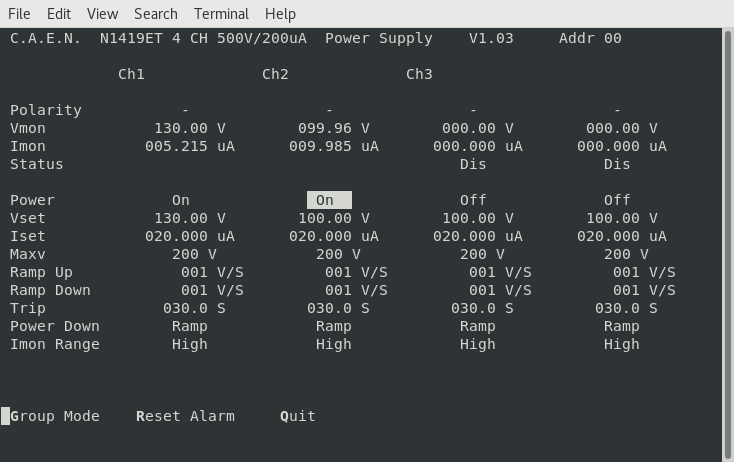
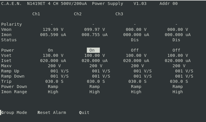
      Rebiassed detectors - leakage current on DSSD2 increased to 9.96uA - Attachment 1

      Power cycling FEEs

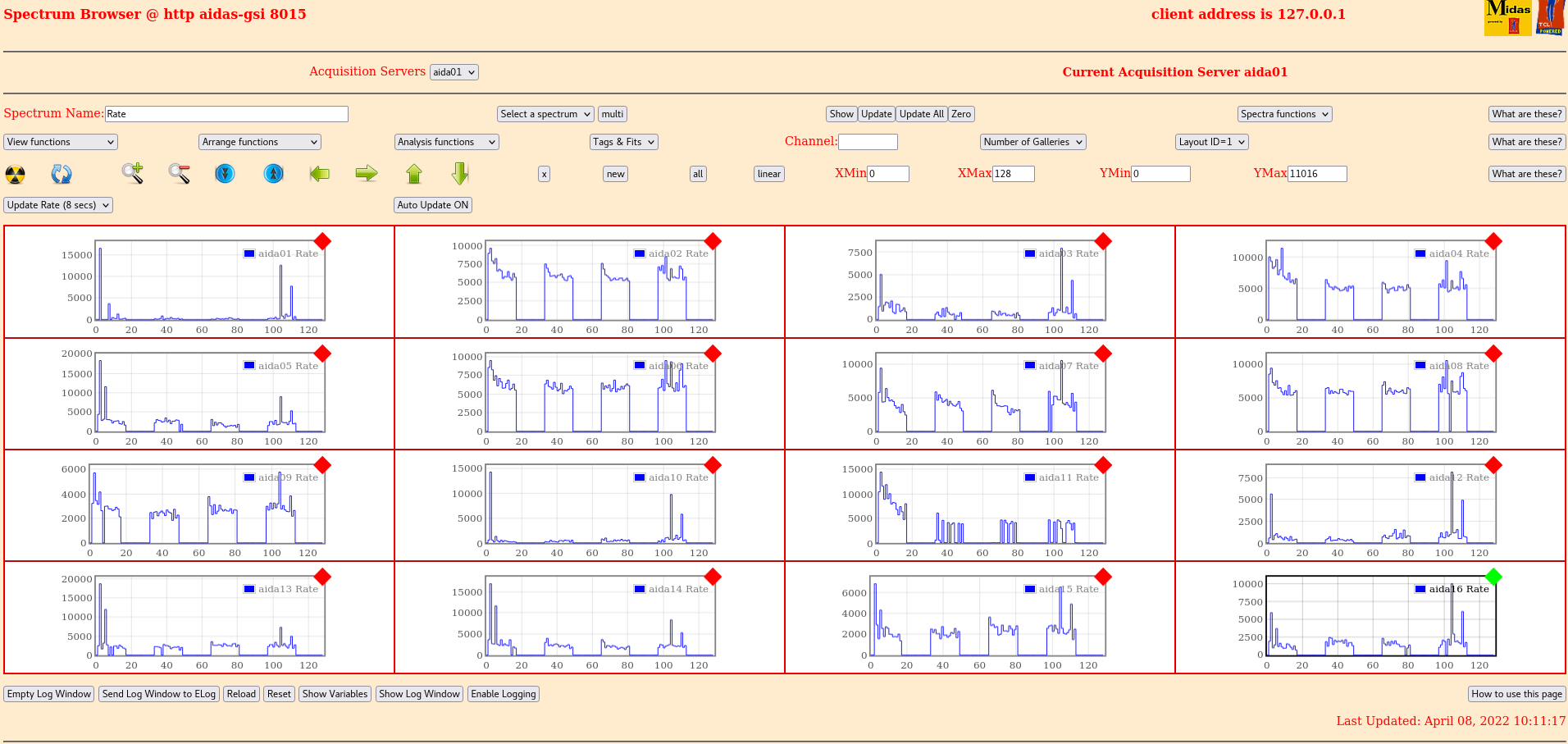
      Following restart the FEEs show some improvement in rates - attachment 2
      Rate spectra - attachment 3
      Still issues with aida11 in the rate spectra (Likely a misaligned ERNI connector)


      Pulser on rate spectra - attachment 4
      Pulser off rate spectra - attachment 5
      We can see that with the pulser on there are events in the channels in aida01 and aida11
      With the pulser off these channels disappear.
      ERNI connector is then likely aligned the issue is more likely the DSSD ribbon cable is misaligned.

      Taking bias off to investigate.


10:39 Could not observe anything out of alignement about either the connectors or the adaptor boards
      Note that after pushing on the connector AIDA01 had largely recovered

13:30 Top of snout taken off while mounted in S4. It was observed that one of the ribbon cables for aida11 was off by 1 row.
      This was corrected in situ and the snout was put back together and made light tight again.
      Oddly leakage current still the same - DSSD2 has come down though - attachment 6
      FEEs powercycled for new tests

      Half the channels in aida11 had appeared again
      Took apart once more and found the other header also off by one row which has been corrected

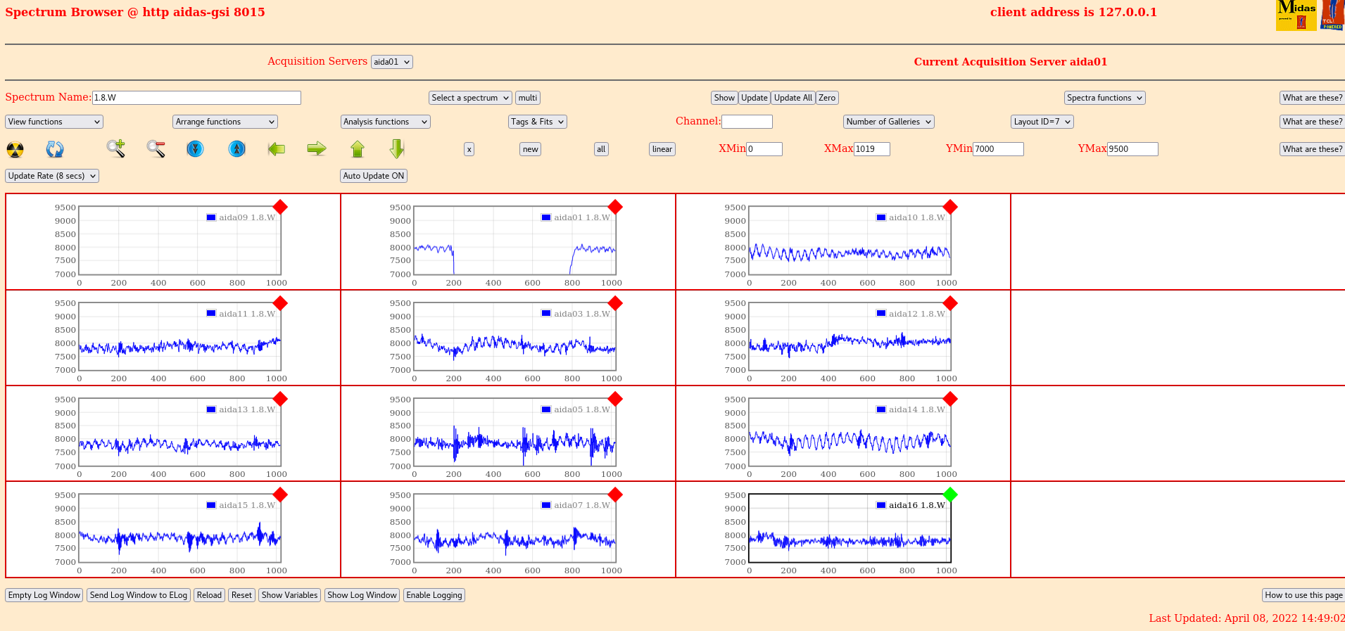
      FEEs powercycled for new test

      All of aida11 now showing - attachment 7
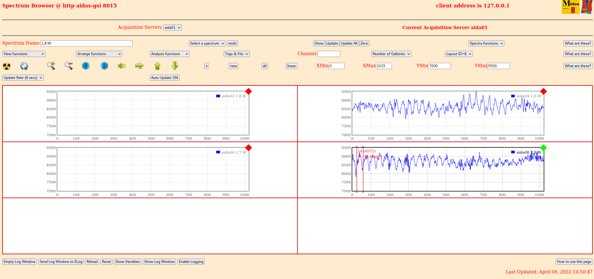
      Statistics at 0xa shown in attachment 8
      All p+n for DSSD1 are good (aida01, 03, 09, 10, 11 and 12)
      p+n for DSSD2 are so so (aida05, 07, 13, 14, 15 and 16)
      All n+n 2, 4, 6 and 8 are poor still


14:50 p+n waveforms - attachment 9
      n+n waveforms - attachment 10

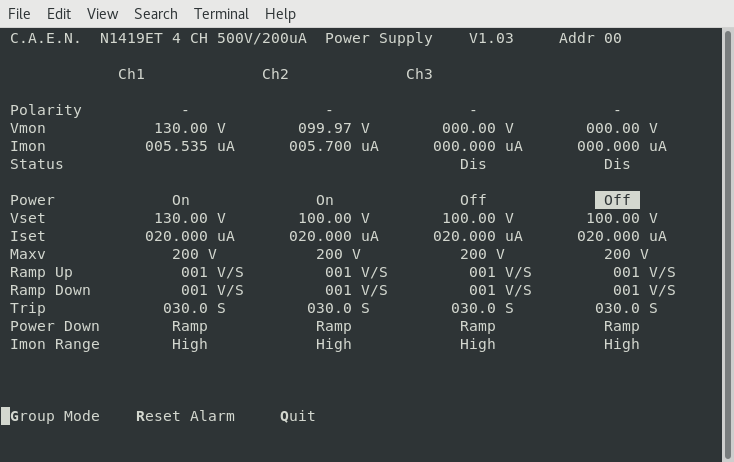
      Current jumper configuration
      LK1 (Bias ground) on FEEs 6 and 8
      LK2&4 on all p+n
      LK3 on aida03 and aida07 (Bottom middle)

15:00 Investigated whether there was a light leak. Placed black material over snout.
      Leakage on DSSD2 dropped to 5.6 - attachment 11
      There was a light leak
      Stats have decreased slightly - attachment 12

16:00 Move raspberry pis atop 5mm alminimum plate to keep away from FEE64 PSUs
      No change

16:30 Remove pulser network from all FEEs
      Rates get noticably worse in many FEEs... why?
      Stats - attachment 13

Possible ideas include braid touching things it shouldn't (Adapter PCBs?) |
| Attachment 1: 220408_1000_bias.png
|
|
| Attachment 2: 220409_1010_Stats.png
|

|
| Attachment 3: 220409_1011_rate.png
|
|
| Attachment 4: 220408_1358_bias.png
|
|
| Attachment 5: 220408_1444_rate.png
|

|
| Attachment 6: 220408_1444_stats.png
|

|
| Attachment 7: 220408_1449_layout7.png
|
|
| Attachment 8: 220408_1451_layout8.png
|
|
| Attachment 9: 220308_1459_bias.png
|
|
| Attachment 10: 220408_1503_stats_post_light.png
|

|
| Attachment 11: 2022-04-08_16-26-30_Stats_No_Pulser.png
|

|
|
|
531
|
Fri Mar 8 16:05:57 2024 |
JB, CC, TD, NH | Friday 8 March |
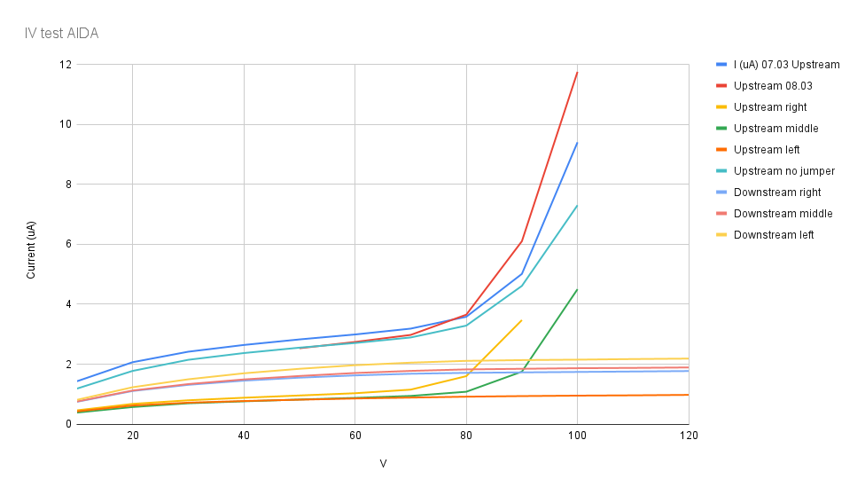
Bias tests of AIDA on individual wafers and in parallel. Spreadsheet can be found in attachment 1, and graphic results can be seen in Attachment 2. Summary: Upstream detector cannot be biased in parallel nor individually. Downstream detector can be biased with positively and each wafer can individually be biased negatively. In parallel, it was not possible to bias the downstream detector negatively as indicated by the tests below.
Test downstream DSSSD with positive polarity bias
Configuration as follows:
CAEN N1419ET ch #3 connected to LHS FEE64 adaptor PCB ( looking upstream ) - LK1 *not* fitted LK1 fitted to 3x ( top )
FEE64 adaptor PCBs Lemo 00.250 jumper cables from/to GND terminals of 3x ( top )
FEE64 adaptor PCBs *and* LHS FEE64 adaptor PCB 1x ( bottom, middle )
FEE64 adaptor PCB connected to ribbon cables but not otherwise connected to anything, LK3 fitted Total 5x adaptor PCBs installed
No other LKs fitted
| Bias Voltage (V) |
Current (uA) |
| +10 |
2.150 |
| +20 |
3.300 |
| +30 |
4.035 |
| +40 |
4.550 |
| +50 |
4.955 |
| +60 |
5.255 |
| +70 |
5.490 |
| +80 |
5.650 |
| +90 |
5.730 |
| +100 |
5.780 |
| +110 |
5.825 |
| +120 |
5.860 |
Nominal V-I curve, stable leakage current. Attachment 3.
Following this success we attempted to repeat test using negative polarity bias
Configuration as follows:
CAEN N1419ET ch #1 connected to ( top, left )
FEE64 adaptor PCB ( looking upstream ) LHS
FEE64 adaptor PCB ( looking upstream ) - LK1 fitted Lemo 00.250 jumper cables from/to BIAS terminals of 3x ( top )
FEE64 adaptor PCBs Lemo 00.250 jumper cable from/to GND terminals of LHS and ( top, left )
FEE64 adaptor PCBs 1x ( bottom, middle )
FEE64 adaptor PCB connected to ribbon cables but not otherwise connected to anything,
LK3 fitted Total 5x adaptor PCBs installed No other LKs fitted With detector bias
-20V we continue to observe the leakage current cycling between 0 and ~2uA with a frequency ~1Hz ( as before )
Copy configuration used for upstream DSSSD test ( which was successful albeit there was detector breakdown at bias voltages > c. 90V )
CAEN N1419ET ch #1 connected to ( bottom, left )
FEE64 adaptor PCB ( looking upstream ) LHS
FEE64 adaptor PCB ( looking upstream ) - LK1 fitted Lemo 00.250 jumper cables from/to BIAS terminals of 3x ( bottom )
FEE64 adaptor PCBs Ground cable jumpered from/to GND terminals LHS, ( left, bottom ), RHS and all 3x top FEE64 adaptor PCBs ( bottom, middle )
FEE64 adaptor PCB LK3 fitted Total 8x adaptor PCBs installed
No other LKs fitted With detector bias -20V we observe leakage current of ~2-3uA.
Current unstable - variations 10-100nA over periods of several seconds Although the leakage current is unstable this is an improvement over previous tests with negative bias. The duplication of upstream and downstream configurations suggests that for some unknown reason it is necessary to connect all 8x FEE64 adaptor PCBs whereas our expectation was that only 4x were necessary.
Summary: Upstream DSSSD Si wafers 1 & 2 breakdown for bias > c. 90V Si wafer 3 OK to 120V Positive bias - not tested Negative bias OK - leakage current stable to c. 90V Downstream DSSSD Si wafers 1, 2 & 3 OK to 120V Positive bias OK Negative bias - leakage current unstable
To do:
1) Disconnect ribbon cables from p+n junction FEE64 adaptor PCBs of upstream DSSSD, apply c. 100V bias and check leakage current is zero i.e. eliminate shorts in PCBs
2) Check that all ribbon cables are properly seated in the adaptor PCBs
3) Check all adaptor PCB connector pins are OK: will need to remove ribbon cables
4) If/when you open check seating of all Kapton PCBs in the DSSSD connectors *and* carefully check that ribbon cable and Kapton PCB connectors are aligned and not out by 1 or 2 rows say.
|
| Attachment 1: IV_test_AIDA.xlsx
|
| Attachment 2: chart.png
|
|
| Attachment 3: Downstream_positive_bias_vs._Current_(uA).png
|
.png.png)
|
|
|
299
|
Fri May 7 13:11:22 2021 |
NH | Friday 7th May |
14:11 - Alpha has been running most of morning

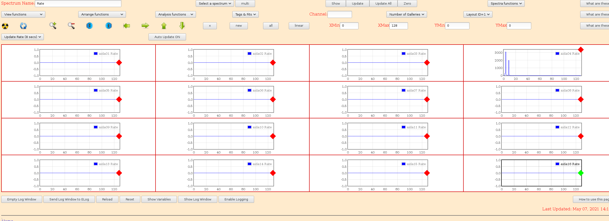
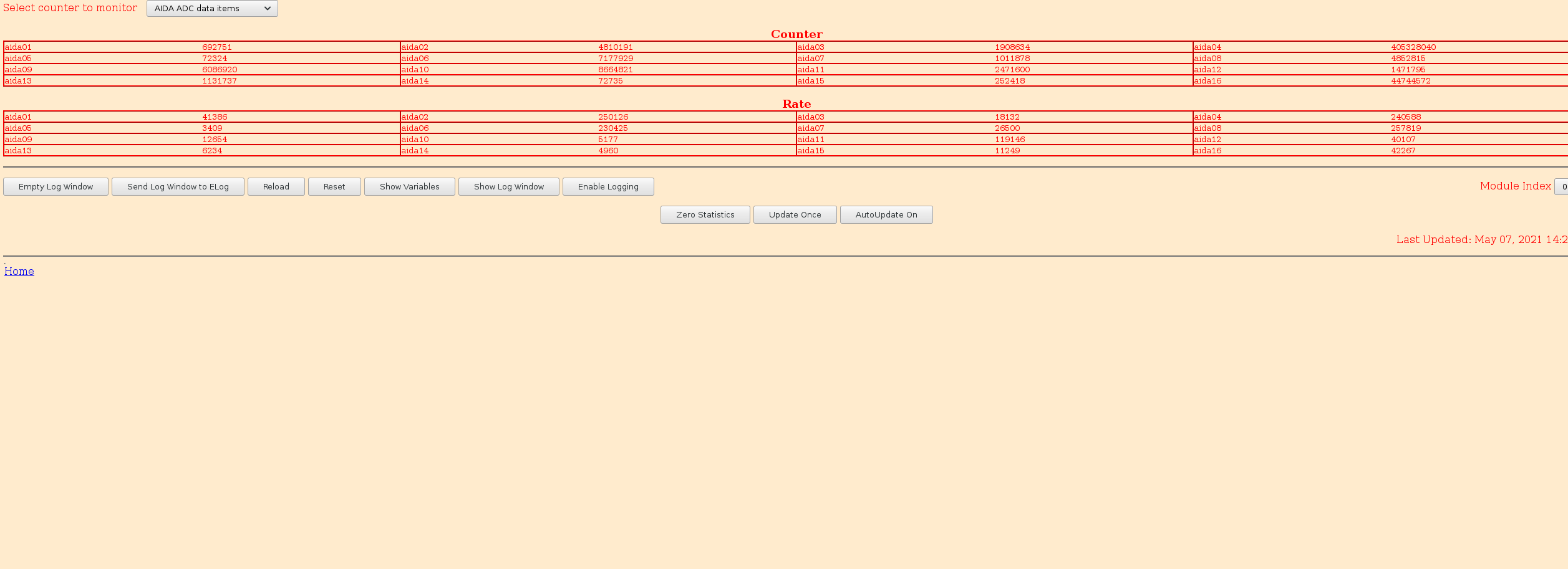
Just saw rates in tape spike to 6 MB/s...
Stop output to tape and look:
ASIC check & load... all rates except aida04 back to 0
Start output to tape
Back to ~300 KB/s

R6_49 will be affected by this.
Others seem OK

System wide check failures:

		 Base 		Current 	Difference
aida01 fault 	 0xb405 : 	 0xb406 : 	 1
aida02 fault 	 0xefc7 : 	 0xefc8 : 	 1
aida03 fault 	 0xdaab : 	 0xdaac : 	 1
aida04 fault 	 0x8f7c : 	 0x8f7d : 	 1
aida05 fault 	 0xb5bd : 	 0xb5be : 	 1
aida06 fault 	 0xeff1 : 	 0xeff2 : 	 1
aida07 fault 	 0x8f57 : 	 0x8f58 : 	 1
aida08 fault 	 0xbef7 : 	 0xbef8 : 	 1
White Rabbit error counter test result: Passed 8, Failed 8

Understand the status reports as follows:-
Status bit 3 : White Rabbit decoder detected an error in the received data
Status bit 2 : Firmware registered WR error, no reload of Timestamp
Status bit 0 : White Rabbit decoder reports uncertain of Timestamp information from WR


			 Base 		Current 		Difference
aida12 fault 	 0x0 : 	 0x200 : 	 512
aida13 fault 	 0x0 : 	 0x61 : 	 97
FPGA Timestamp error counter test result: Passed 14, Failed 2
If any of these counts are reported as in error
The ASIC readout system has detected a timeslip.
That is the timestamp read from the time FIFO is not younger than the last


The FPGA errors seem to come on FEEs with no WR errors or clock errors (including Lock/PLL page)

Temps & Rates OK

Will now stop Alpha run and check noise situation

Run stopped at R6_49

Switching to nostorage (NOTAPE/R2)

Set ASICs to threshold 0xa, Rates OK
Rate to Tape/MBS ca 9 MB/s

No change to situation since yesterday... good sign

During MBS test aida13 rebooted... crash log from ttyUSB5 attached

It was later noticed connector half off in aida05, reseated and after some time got noise levels OK again...
cables on top very sensitive, indicative of issues inside maybe(?). We avoid touching AIDA for now :)

A power cycle of all FEEs was performed after aida13's reboot to make sure things are good.
All systems check OK |
| Attachment 1: elog_locks.png
|

|
| Attachment 2: elog_temps.png
|

|
| Attachment 3: elog_rates.png
|
|
| Attachment 4: elog_rates1.png
|
|
| Attachment 5: aida13.txt
|
06/19:25:39|Data Acquisition Statistics counters now cleared^M
06/19:25:55|Clear Statistics (1)^M
06/19:25:55|------------[ cut here ]------------^M
07/15:23:58|kernel BUG at mm/slab.c:2974!^M
07/15:23:58|Oops: Exception in kernel mode, sig: 5 [#1]^M
07/15:23:58|PREEMPT Xilinx Virtex440^M
07/15:23:59|Modules linked in: aidamem xdriver xh_spidev_register^M
07/15:23:59|NIP: c009211c LR: c00920b0 CTR: 00000007^M
07/15:23:59|REGS: c0391bf0 TRAP: 0700   Not tainted  (2.6.31)^M
07/15:23:59|MSR: 00021000 <ME,CE>  CR: 24022048  XER: 00000000^M
07/15:23:59|TASK = c036e318[0] 'swapper' THREAD: c0390000^M
07/15:23:59|GPR00: 00000001 c0391ca0 c036e318 c680daf0 c694003c 0000000a c6940020 00000009 ^M
07/15:23:59|GPR08: 0000001b c680dae0 00000cf0 c680dae0 24008042 00005aa8 c03a0000 00000020 ^M
07/15:23:59|GPR16: c0390000 c03a069c c03a0000 c038c384 c038cc18 00000020 00000000 00200200 ^M
07/15:23:59|GPR24: 00100100 c0390000 00000000 c680dae8 c680dae0 c680ae00 00000006 c680e400 ^M
07/15:23:59|NIP [c009211c] cache_alloc_refill+0x130/0x608^M
07/15:23:59|LR [c00920b0] cache_alloc_refill+0xc4/0x608^M
07/15:23:59|Call Trace:^M
07/15:23:59|[c0391ca0] [c00920b0] cache_alloc_refill+0xc4/0x608 (unreliable)^M
07/15:23:59|[c0391d00] [c00927d8] kmem_cache_alloc+0xc4/0xcc^M
07/15:23:59|[c0391d20] [c0042420] __sigqueue_alloc+0x50/0xb8^M
07/15:23:59|[c0391d40] [c0042938] __send_signal+0x78/0x260^M
07/15:23:59|[c0391d70] [c0042f78] group_send_sig_info+0x70/0x9c^M
07/15:24:00|[c0391da0] [c00438a8] kill_pid_info+0x48/0x8c^M
07/15:24:00|[c0391dc0] [c0038e8c] it_real_fn+0x1c/0x30^M
07/15:24:00|[c0391dd0] [c0050c40] hrtimer_run_queues+0x184/0x240^M
07/15:24:00|[c0391e30] [c0040ba8] run_local_timers+0x10/0x2c^M
07/15:24:00|[c0391e40] [c0040bf4] update_process_times+0x30/0x70^M
07/15:24:00|[c0391e60] [c005a000] tick_periodic+0x34/0xe8^M
07/15:24:00|[c0391e70] [c005a0d4] tick_handle_periodic+0x20/0x120^M
07/15:24:00|[c0391eb0] [c000af70] timer_interrupt+0xa4/0x10c^M
07/15:24:00|[c0391ed0] [c000e9c4] ret_from_except+0x0/0x18^M
07/15:24:00|[c0391f90] [c0006fac] cpu_idle+0xcc/0xdc^M
07/15:24:00|[c0391fb0] [c000172c] rest_init+0x70/0x84^M
07/15:24:00|[c0391fc0] [c0341854] start_kernel+0x230/0x2ac^M
07/15:24:00|[c0391ff0] [c0000204] skpinv+0x194/0x1d0^M
07/15:24:00|Instruction dump:^M
07/15:24:00|2f1e0000 409900f4 387c0010 3b7c0008 80dc0000 7f9c3000 419e014c 81060010 ^M
07/15:24:00|801d001c 7c004010 38000000 7c000114 <0f000000> 81260010 801d001c 7f804840 ^M
07/15:24:00|Kernel panic - not syncing: Fatal exception in interrupt^M
07/15:24:00|Call Trace:^M
07/15:24:00|[c0391a40] [c0005de8] show_stack+0x44/0x16c (unreliable)^M
07/15:24:00|[c0391a80] [c00345bc] panic+0x94/0x168^M
07/15:24:01|[c0391ad0] [c000bd44] die+0x178/0x18c^M
07/15:24:01|[c0391af0] [c000c000] _exception+0x164/0x1b4^M
07/15:24:01|[c0391be0] [c000e978] ret_from_except_full+0x0/0x4c^M
07/15:24:01|[c0391ca0] [c00920b0] cache_alloc_refill+0xc4/0x608^M
07/15:24:01|[c0391d00] [c00927d8] kmem_cache_alloc+0xc4/0xcc^M
07/15:24:01|[c0391d20] [c0042420] __sigqueue_alloc+0x50/0xb8^M
07/15:24:01|[c0391d40] [c0042938] __send_signal+0x78/0x260^M
07/15:24:01|[c0391d70] [c0042f78] group_send_sig_info+0x70/0x9c^M
07/15:24:01|[c0391da0] [c00438a8] kill_pid_info+0x48/0x8c^M
07/15:24:01|[c0391dc0] [c0038e8c] it_real_fn+0x1c/0x30^M
07/15:24:01|[c0391dd0] [c0050c40] hrtimer_run_queues+0x184/0x240^M
07/15:24:01|[c0391e30] [c0040ba8] run_local_timers+0x10/0x2c^M
07/15:24:01|[c0391e40] [c0040bf4] update_process_times+0x30/0x70^M
07/15:24:01|[c0391e60] [c005a000] tick_periodic+0x34/0xe8^M
07/15:24:01|[c0391e70] [c005a0d4] tick_handle_periodic+0x20/0x120^M
07/15:24:01|[c0391eb0] [c000af70] timer_interrupt+0xa4/0x10c^M
07/15:24:01|[c0391ed0] [c000e9c4] ret_from_except+0x0/0x18^M
07/15:24:01|[c0391f90] [c0006fac] cpu_idle+0xcc/0xdc^M
07/15:24:01|[c0391fb0] [c000172c] rest_init+0x70/0x84^M
07/15:24:01|[c0391fc0] [c0341854] start_kernel+0x230/0x2ac^M
07/15:24:02|[c0391ff0] [c0000204] skpinv+0x194/0x1d0^M
07/15:24:02|Rebooting in 180 seconds..
07/15:27:02|^MISOL Version 1.00 Date 9th January 2017
|