| ID |
Date |
Author |
Subject |
|
19
|
Wed Aug 3 14:48:09 2016 |
Sarah | Leakage currents 02.08 - 03.08 |
02.08:
dE = 0.03 uA
E = 0.03 uA
PHDI = 0.04 uA
03.08:
dE = 0.03 uA
E 0.04 uA
PHDI = 0.04 uA |
|
20
|
Mon Aug 8 11:02:13 2016 |
Sarah | Leakage currents 08.08.16 |
E 0.03 uA
dE 0.04 uA
PHDI 0.05 uA
Boron target 1 towards PHDI and Boron target 3 towards dE-E.
Mylar target gluing in electronics lab. |
|
21
|
Tue Aug 9 15:57:52 2016 |
Sarah | Leakage currents 09.08.16 |
Morning - 9am
E= 0.03uA
dE= 0.04uA
PHDI= 0.06uA
Afternoon - 4.30pm
E=0.03uA
dE= 0.03uA
PHDI=0.05uA
|
|
22
|
Thu Aug 11 08:19:37 2016 |
Sarah | Leakage currents 10.8.16 |
At lunchtime (12.45)
E = 0.03 uA
dE = 0.04 uA
PHDI = 0.06 uA |
|
23
|
Wed Aug 17 15:10:05 2016 |
Sarah | Leakage currents 12.08.16 |
E = 0.03uA
dE = 0.04uA
PHDI = 0.06uA
- Monitor PHDI - increasing slowly... |
|
25
|
Fri Sep 2 12:01:57 2016 |
Sarah | Leakage currents 02.09.16 |
E 0.03
dE 0.05
PHDI 0.12
Check on PHDI pulser width:
205170 (first in beam run) - 1.1% FWHM (at 8275 ch)
205439 (01/09/16) - 1.0% FWHM (at 8008 ch)
Seems to be holding up OK at present. |
|
26
|
Fri Sep 2 12:03:40 2016 |
Sarah | SPD card changed |
14 bit card replaced for DEED 9-12, to prevent issue with pulser arriving before gamma flash. |
|
27
|
Fri Sep 9 10:01:18 2016 |
Sarah | Leakage currents 09.09.16 |
EFED 0.04uA
DEED 0.05uA
PHDI 0.13uA |
|
31
|
Thu Oct 6 11:07:47 2022 |
Nikolay Sosnin | Change of sample/Addition of pulser |
Changed from LiF 4 to LiF 3 after running with LiF 4 overnight (run title on n_TOF DAQ was not updated to refelect the change, and still says LiF 4, but the material setting of the run states correctly that hte run is with LiF 3).
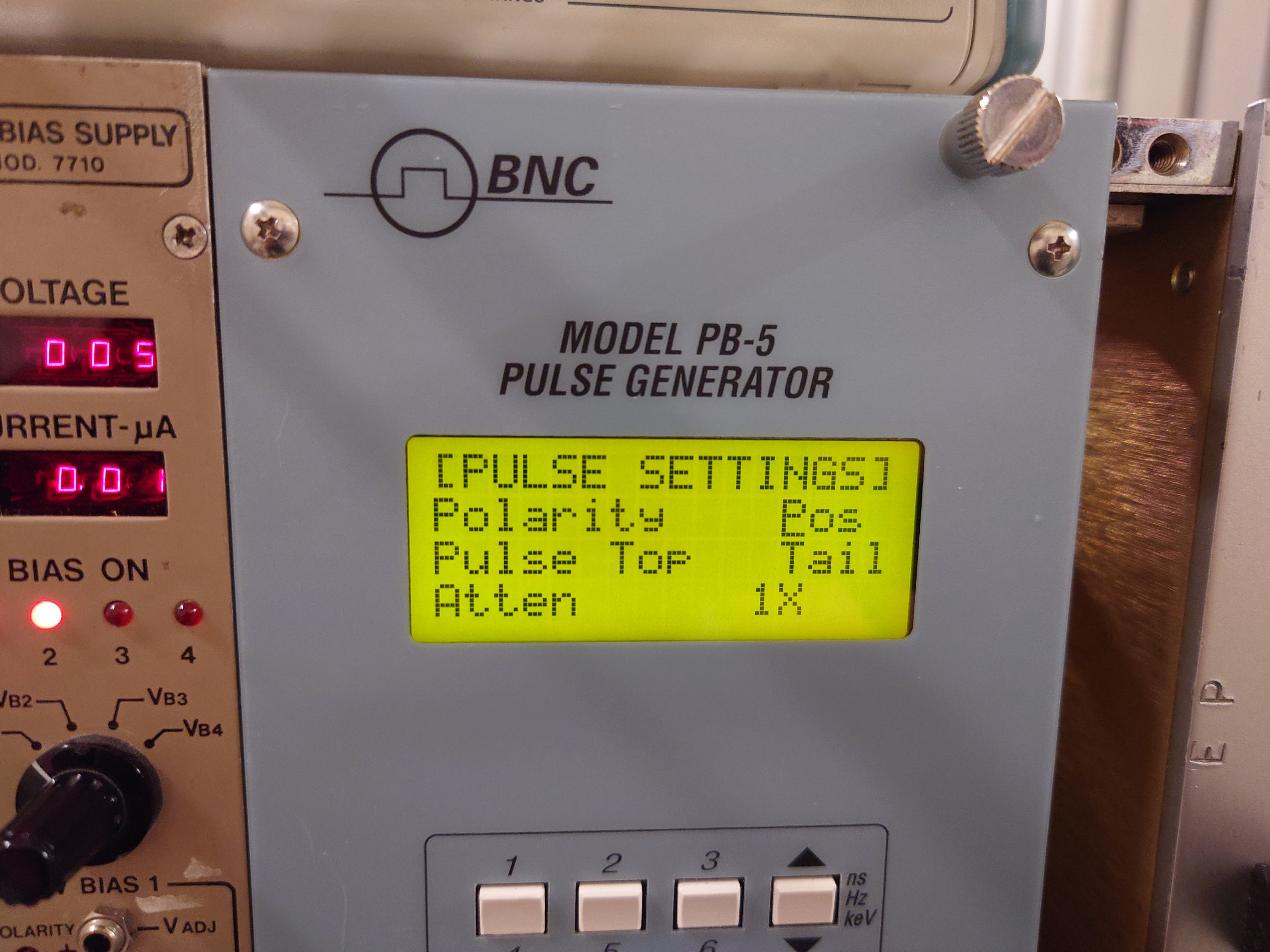
Added pulser triggered from protons. 12 microsecond delay from protons to gamma-flash + 1.75 microsecond delay from gamma flash to pulser. 20 mV pulser output into 50 ohm impedance (10 mV final output) of both polarities (using two pulsers, one NE pulser and one BNC PB5 pulser). Planning torun with 1.75 microsecond delay for approx. 1 hour, change to 5 microsecond delay. |
|
32
|
Thu Oct 6 11:45:39 2022 |
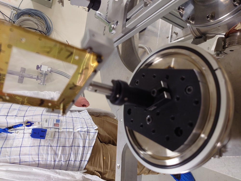
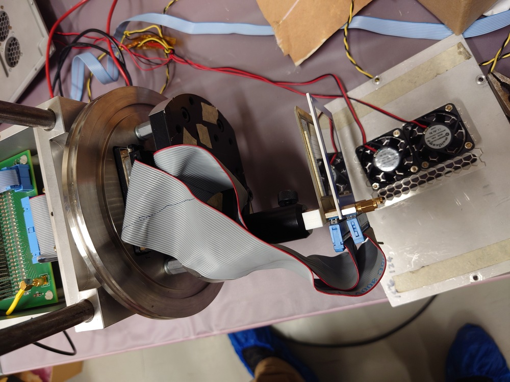
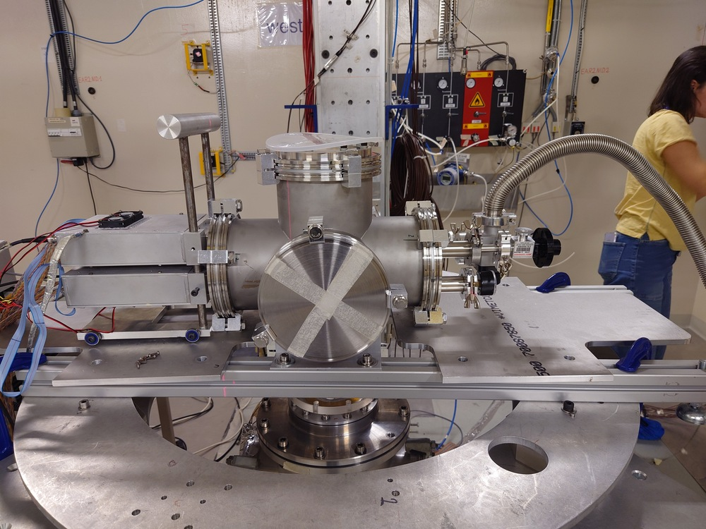
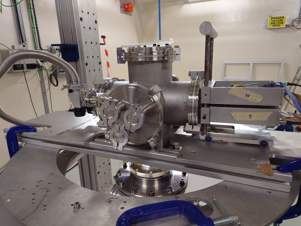
Nikolay Sosnin | Assembly Setup Days 1 and 2 |
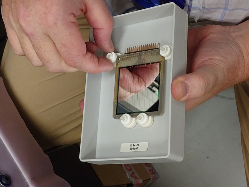
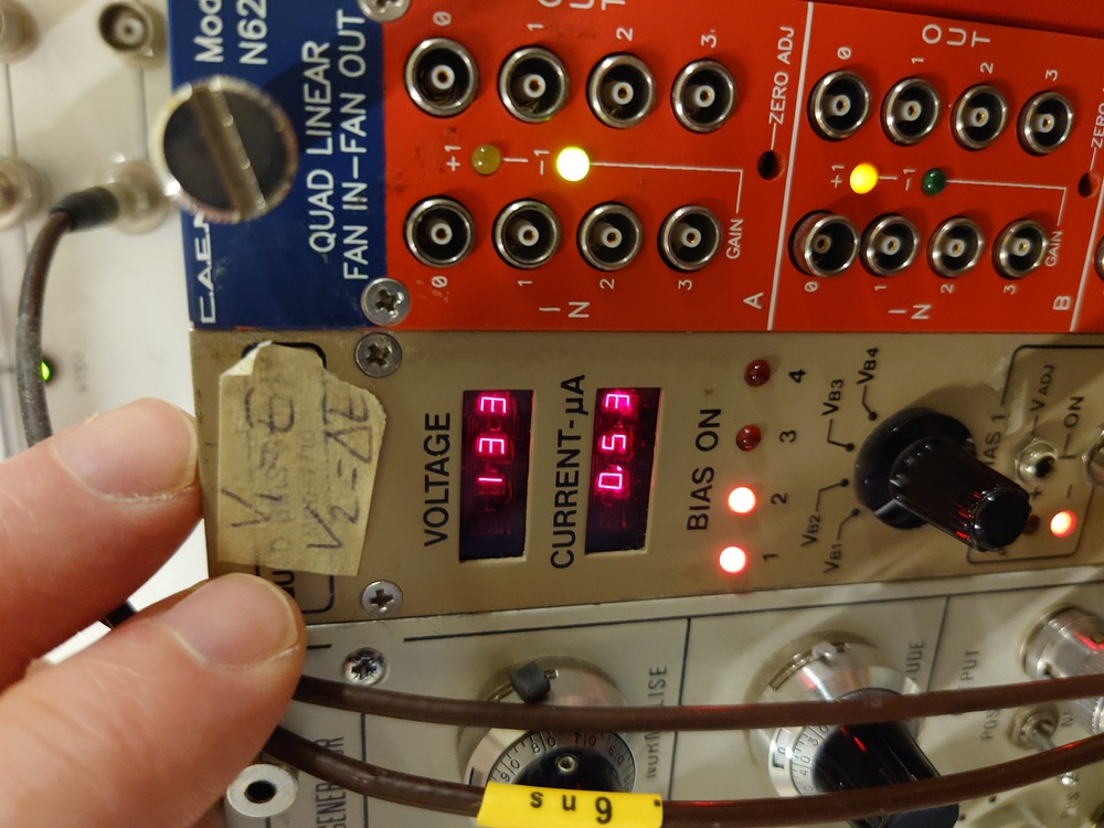
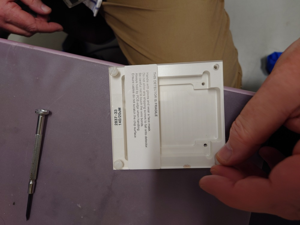
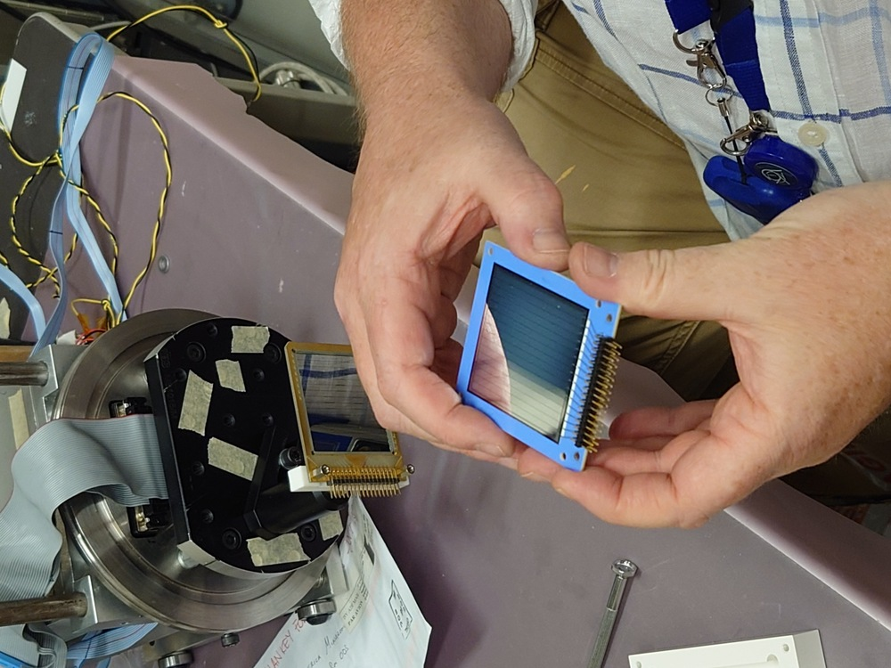
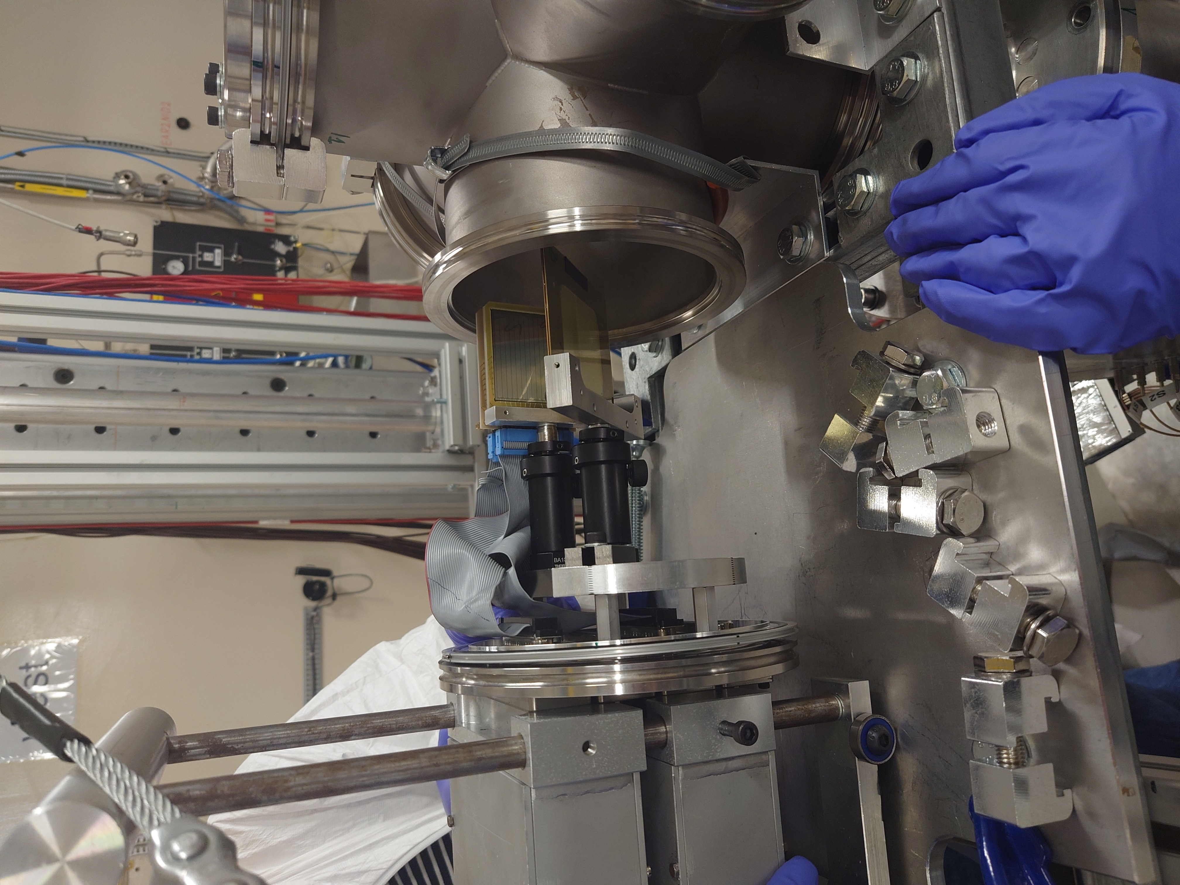
Photographs of assembly up to the first pulser test with LiF3. |
| Attachment 1: LiF4_Mounted_On_Trolley_Resize.jpg
|

|
| Attachment 2: Mounted_Detectors_Resize.jpg
|

|
| Attachment 3: Rail_Clamps_Resize.jpg
|

|
| Attachment 4: Target_Holder_Mount_Resize.jpg
|

|
| Attachment 5: Vacuum_Side_Resize.jpg
|

|
| Attachment 6: LiF4_Final_Position_Resize.jpg
|

|
| Attachment 7: LiF4_In_Chamber_Resize.jpg
|

|
| Attachment 8: LiF4_Mounted_2_Resize.jpg
|

|
| Attachment 9: LiF4_Mounted_Resize.jpg
|
|
| Attachment 10: Final_Readout_Connection_Both_Resize.jpg
|
|
| Attachment 11: Full_Assembly_Resize.jpg
|
|
| Attachment 12: Full_Assembly_Target_Holder_View_Resize.jpg
|
|
| Attachment 13: LiF3_Final_Position_Resize.jpg
|

|
| Attachment 14: LiF3_Holder_Resize.jpg
|

|
| Attachment 15: E_Box_Resize.jpg
|

|
| Attachment 16: E_Detector_Resize.jpg
|
|
| Attachment 17: E_Mounted_Resize.jpg
|

|
| Attachment 18: E_Voltage_Resize.jpg
|
|
| Attachment 19: dE_Box_Resize.jpg
|
|
| Attachment 20: dE_Detector_Resize.jpg
|
|
| Attachment 21: dE_Readout_Connection_Resize.jpg
|

|
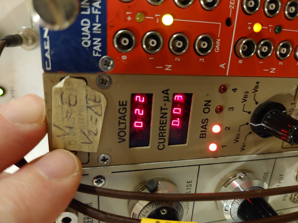
| Attachment 22: dE_Voltage_Resize.jpg
|
|
| Attachment 23: Detector_Holder_Mount_Resize.jpg
|

|
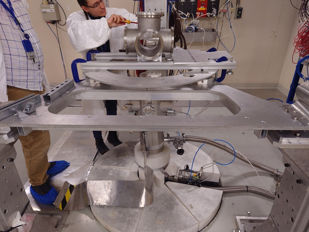
| Attachment 24: Central_Chamber_Mounted_Rails_Resize.jpg
|
|
| Attachment 25: Chamber_Support_Resize.jpg
|

|
|
33
|
Thu Oct 6 14:58:29 2022 |
Nikolay Sosnin | Change of Pulser Delay |
Still using pulser triggered from protons. 12 microsecond delay from protons to gamma-flash + 1.75 microsecond delay from gamma flash to pulser. 20 mV pulser output into 50 ohm impedance (10 mV final output) of both polarities (using two pulsers, one NE pulser and one BNC PB5 pulser). Changed pulser setting to run with 5 microsecond delay for approx. 1 hour, then change to 10 microsecond delay. |
|
34
|
Fri Oct 7 17:17:08 2022 |
Nikolay Sosnin | Change of Pulser Delay |
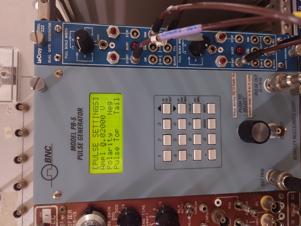
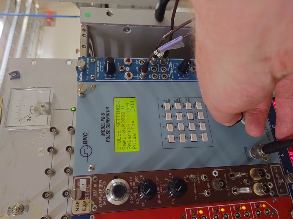
Still using pulser triggered from protons. 12 microsecond delay from protons to gamma-flash + 11 microsecond delay from gamma flash to pulser. 20 mV pulser output into 50 ohm impedance (10 mV final output) of both polarities (using two pulsers, one NE pulser and one BNC PB5 pulser). Changed pulser setting to run with 11 microsecond delay for approx. 2 hour, then change to an overnight run with pulser running NOT triggered from beam. |
|
35
|
Fri Oct 7 20:04:30 2022 |
Nikolay Sosnin | Change of Pulser Setting |
The pulser has been switched from triggering from beam trigger to running at a 10 Hz rate, and will now appear in random places in signal traces. Planned to run overnight measuring LiF3, switch to empty + detector in beam in the morning. |
|
36
|
Sat Oct 8 11:56:49 2022 |
Nikolay Sosnin | Silicon Strips of Concern |
DEED 6 and 9 no signal throughout the campaign.
EFED 27 high oscillations in baseline throughout the campaign. |
|
37
|
Sat Oct 8 11:57:36 2022 |
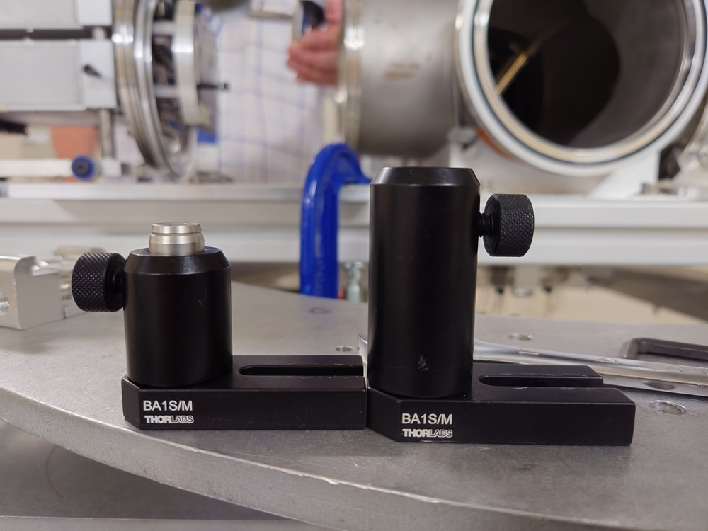
Nikolay Sosnin | Change of Detector-Target Separation |
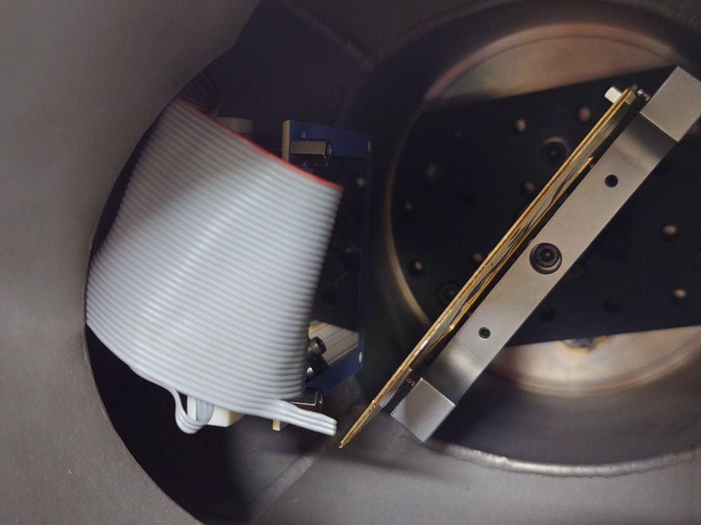
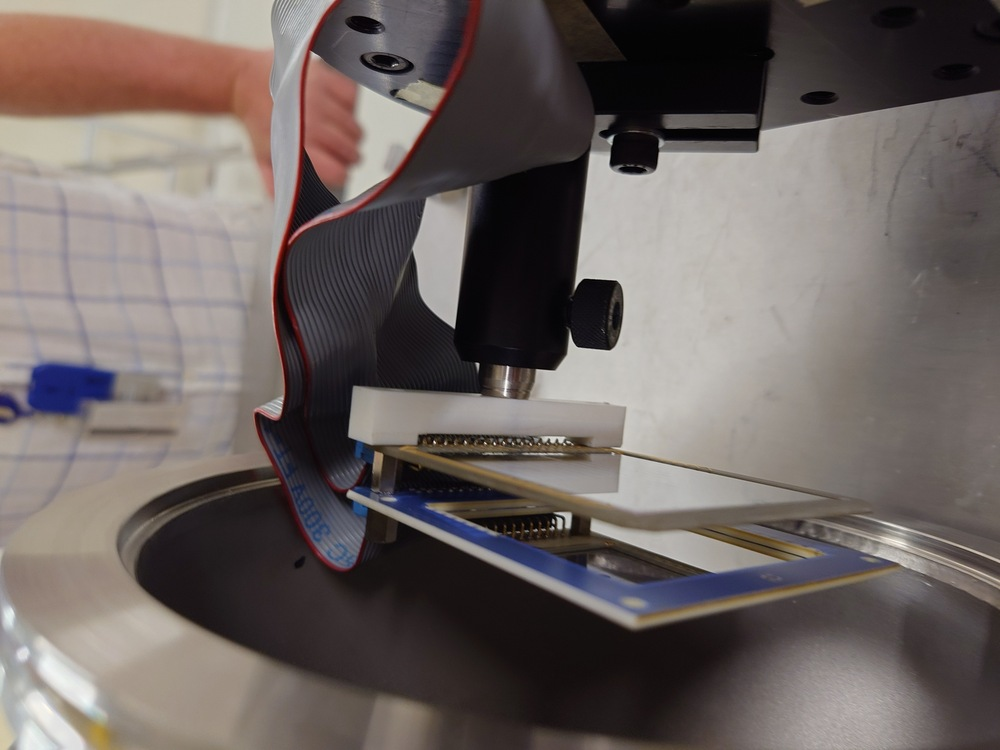
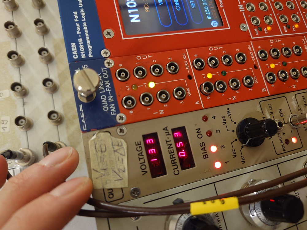
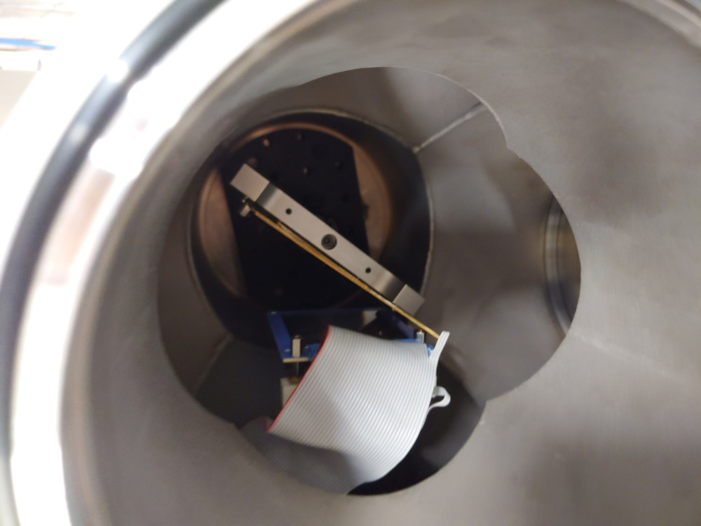
Increased detector-target (LiF 3) separation by 1.5 cm. Had to replace the support strut under the detectors due to the previous one being fuly retracted even for minimal target-detector separation. This change may affect detector rotation relative to the target. |
| Attachment 1: Positive_Pulser_Resize.jpg
|

|
| Attachment 2: Short_Det_Holder_In_Place_Resize.jpg
|

|
| Attachment 3: Short_Holder_In_Chamber_Resize.jpg
|
|
| Attachment 4: Initia_Det_Holder_Config_Resize.jpg
|
|
| Attachment 5: Negative_Pulser1_Resize.jpg
|
|
| Attachment 6: Negative_Pulser2_Resize.jpg
|

|
| Attachment 7: Negative_Pulser3_Resize.jpg
|
|
| Attachment 8: Negative_Pulser3_Resize.jpg
|

|
| Attachment 9: Negative_Pulser4_Resize.jpg
|

|
| Attachment 10: E_Voltage2_Resize.jpg
|
|
| Attachment 11: E_Voltage3_Resize.jpg
|

|
| Attachment 12: Initial_dE_LiF3_Distance_Resize.jpg
|
|
| Attachment 13: Initial_Holder_Back_View_Resize.jpg
|
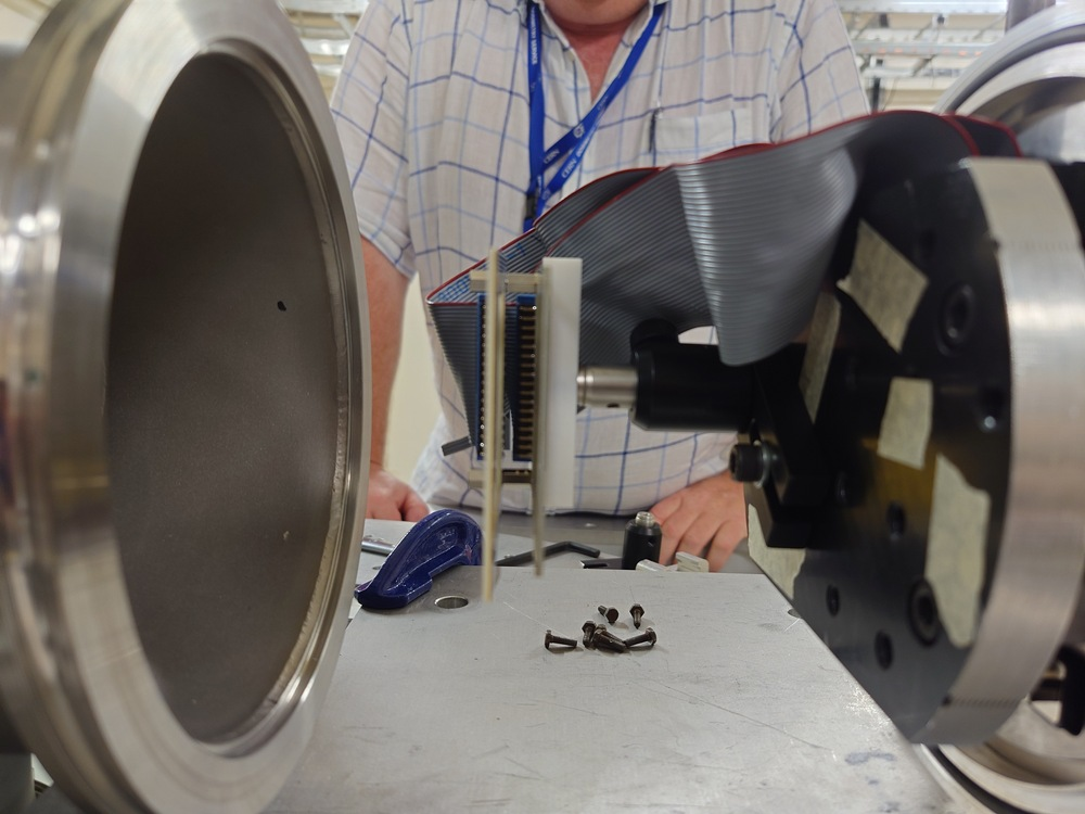
|
| Attachment 14: Initial_Holder_Front_View_Resize.jpg
|

|
| Attachment 15: dE_Voltage2_Resize.jpg
|
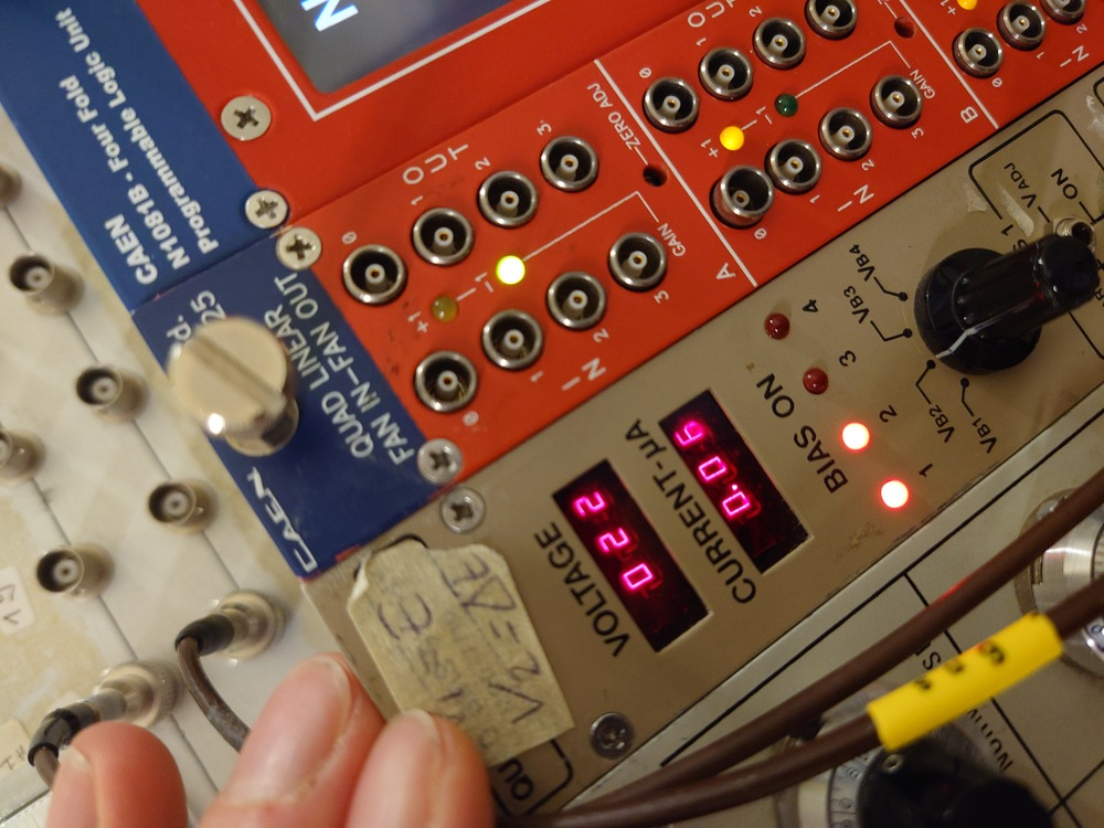
|
| Attachment 16: dE_Voltage3_Resize.jpg
|

|
| Attachment 17: Det_Holder_Stand_Replacement_to_Short_Resize.jpg
|
|
|
38
|
Sun Oct 9 20:57:54 2022 |
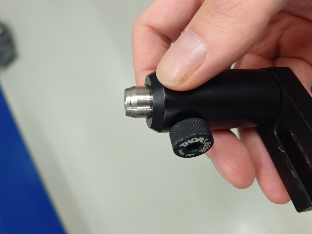
Nikolay Sosnin | Detectors in-beam, no target |
After long beam-off, changed detector mount by moving it 2 cm forward into the beam, after removing LiF 3. |
| Attachment 1: Det_Holder_Default_Position_Resize.jpg
|
|
| Attachment 2: Detectors_in_Beam_CloseUp_Resize.jpg
|

|
| Attachment 3: Detectors_in_Beam_Resize.jpg
|

|
| Attachment 4: Voltage_E_InBeam_AfterNeutrons_Resize.jpg
|

|
| Attachment 5: Voltage_E_InBeam_BeforeNeutrons_Resize.jpg
|

|
| Attachment 6: Mounted_LiF3_Resize.jpg
|

|
| Attachment 7: Voltage_dE_InBeam_AfterNeutrons_Resize.jpg
|

|
| Attachment 8: Voltage_dE_InBeam_BeforeNeutrons_Resize.jpg
|

|
| Attachment 9: Gamma_Flash_InBeam_1_Resize.jpg
|

|
| Attachment 10: Gamma_Flash_InBeam_2_Resize.jpg
|

|
| Attachment 11: LiF3_Mount_Angle_View1_Resize.jpg
|

|
| Attachment 12: LiF3_Mount_Angle_View2_Resize.jpg
|
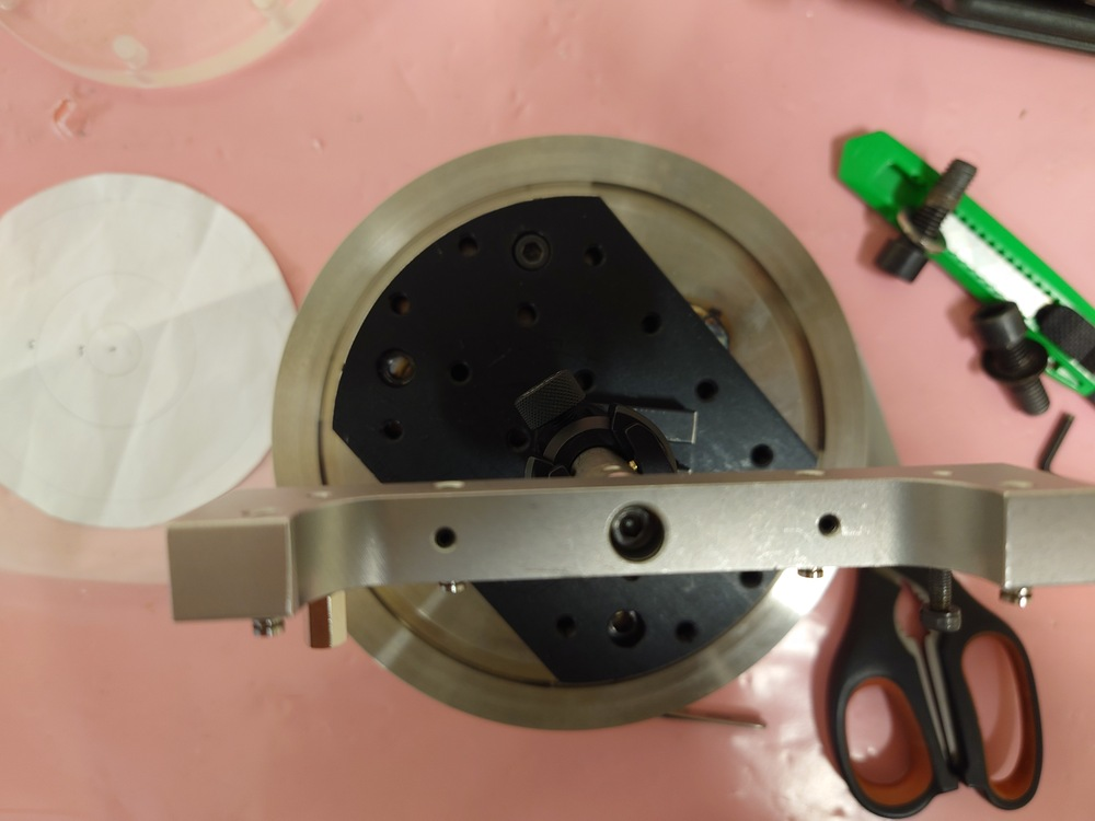
|
|
40
|
Sun Oct 9 21:07:02 2022 |
Nikolay Sosnin | Boron Sample 3 Measurement |
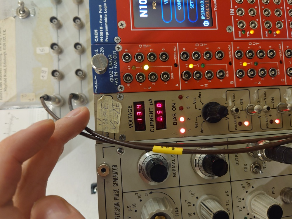
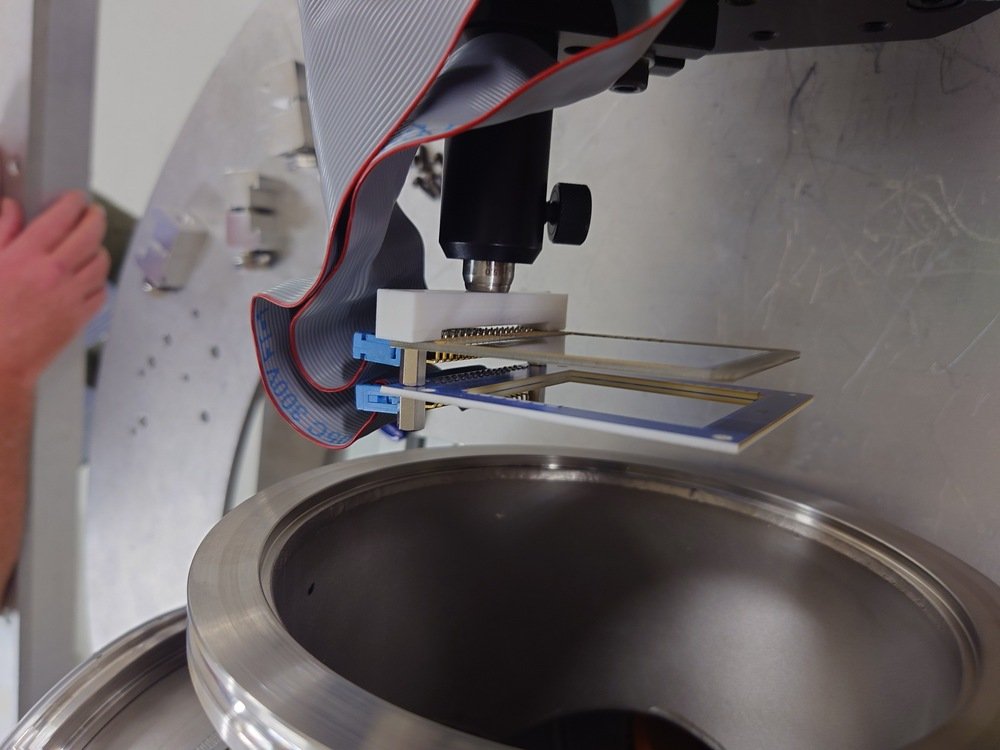
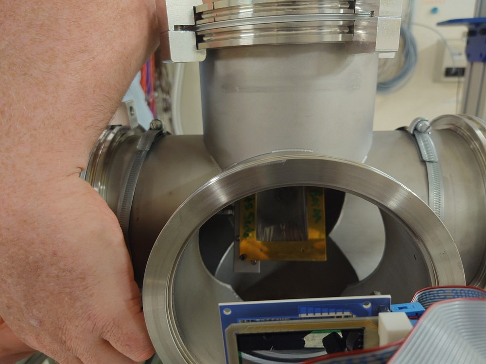
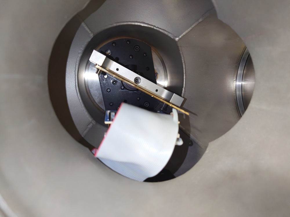
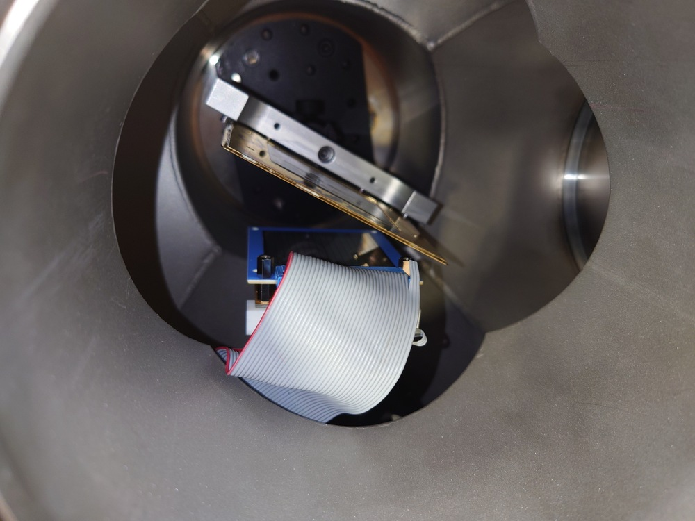
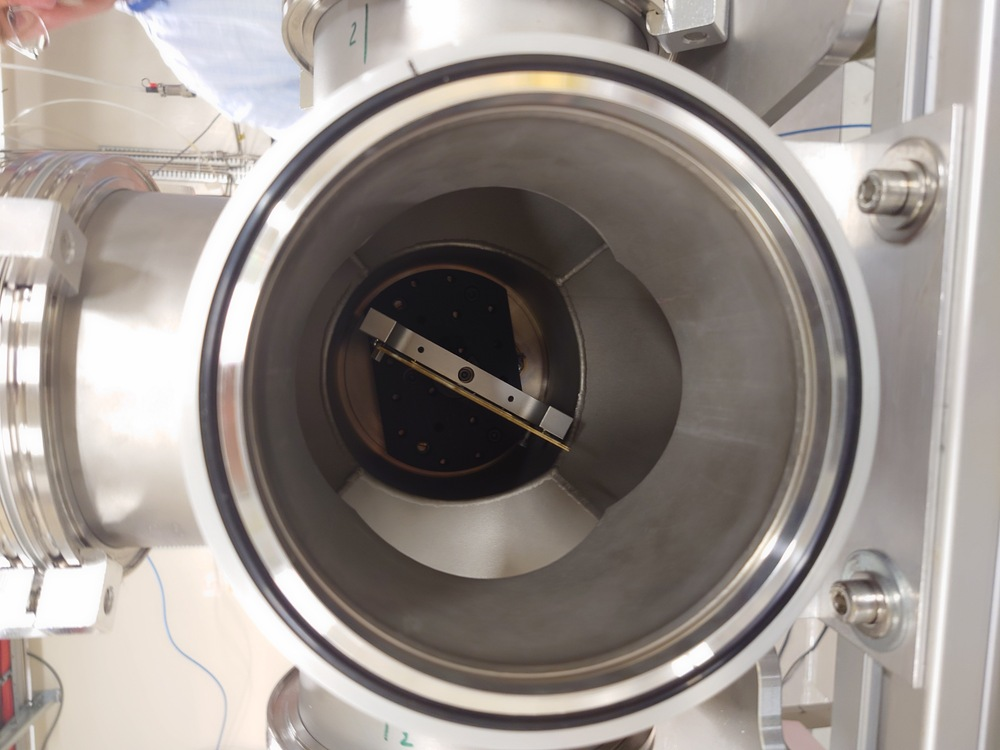
21:15 Changed from detectors in-beam to boron-10 sample 3 in-beam (in-beam measurement got 1000 triggers, 500 of which were dedicated). The sample was mounted identically to LiF 3. An attempt was made to replace the 20-micron dE detector with a 50-micron one, but the screwholes on the 50-micron detector did not match the 300-micron E-detector ones and therefore could not be mounted. 20-micron detector was therefore re-attached. Planning to run for 12 hours with boron than dismount. |
| Attachment 1: Voltage_dE4_Resize.jpg
|

|
| Attachment 2: Voltage_E4_Resize.jpg
|
|
| Attachment 3: E_dE_Position_Before_Boron_Resize.jpg
|

|
| Attachment 4: E_dE_Position_Boron_Above_Resize.jpg
|

|
| Attachment 5: E_dE_Position_Boron_Back_Resize.jpg
|

|
| Attachment 6: E_dE_Position_Boron_Resize.jpg
|
|
| Attachment 7: Boron_Sample_Rotation_Angle_Resize.jpg
|

|
| Attachment 8: Boron_Sample3_Target_View_Resize.jpg
|
|
| Attachment 9: Boron_Measurement_Chamber_Interior2_Resize.jpg
|
|
| Attachment 10: Boron_Mounted_Resize.jpg
|

|
| Attachment 11: Boron_Measurement_Chamber_Interior1_Resize.jpg
|
|
| Attachment 12: Boron_Sample3_Back_Resize.jpg
|

|
| Attachment 13: Boron_Sample3_Front_Resize.jpg
|

|
| Attachment 14: Boron_Sample3_InBeam_Resize.jpg
|
|
|
44
|
Mon Jul 31 10:21:41 2023 |
Nikolay Sosnin | n_TOF Data and Filtering |
|
| Attachment 1: Al26_Filtering.pptx
|
|
50
|
Thu Aug 10 10:50:15 2023 |
Nikolay Sosnin | Al26 Chamber Cabling/Vacuum/NIM |
|
| Attachment 1: Vacuum_Reading.JPG
|

|
| Attachment 2: Pulser_Settings3.JPG
|
|
| Attachment 3: Pulser_Settings2.JPG
|

|
| Attachment 4: NIM_Bin.JPG
|

|
| Attachment 5: Currents.JPG
|
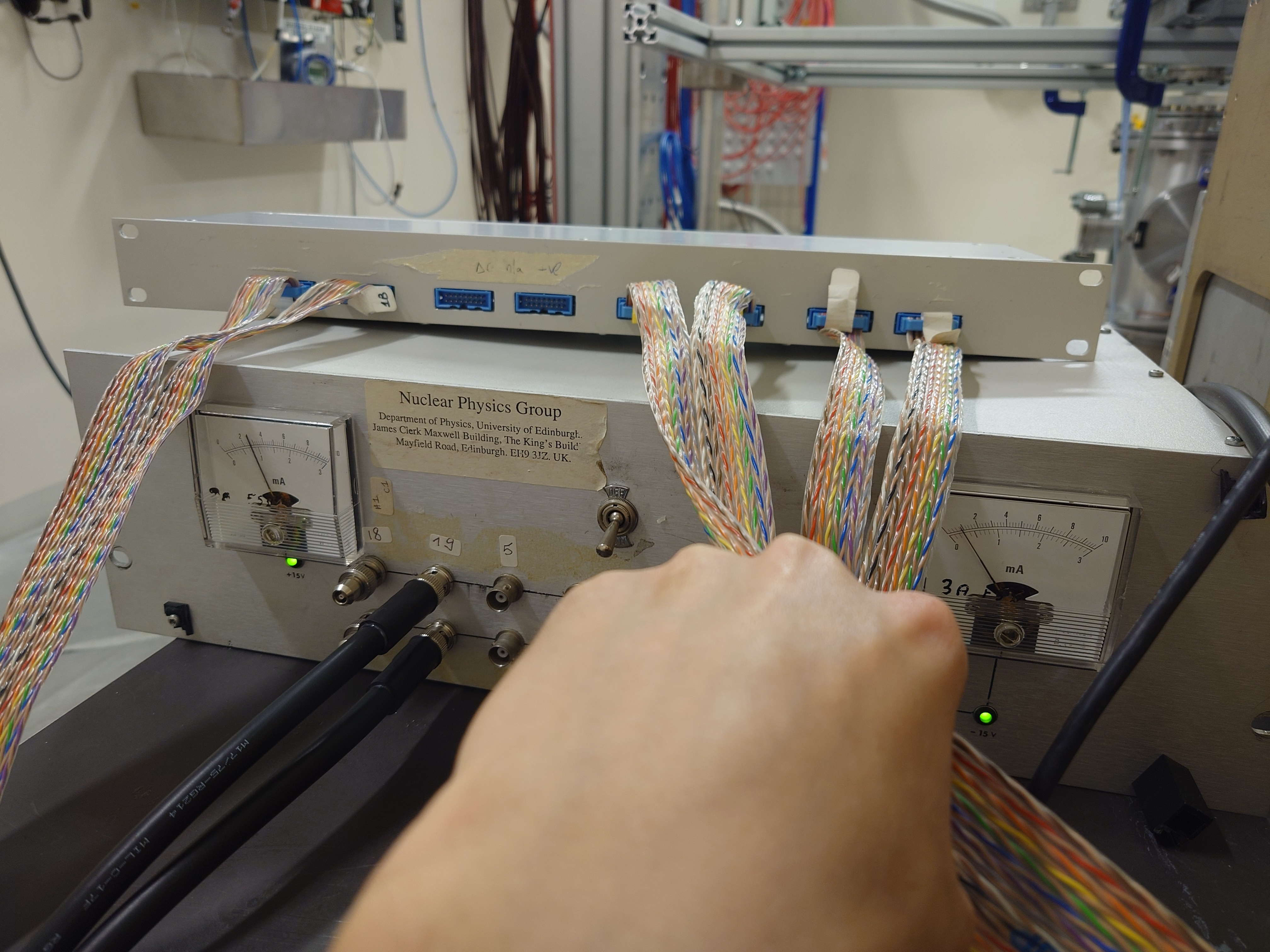
|
| Attachment 6: Amplifier_Settings.JPG
|
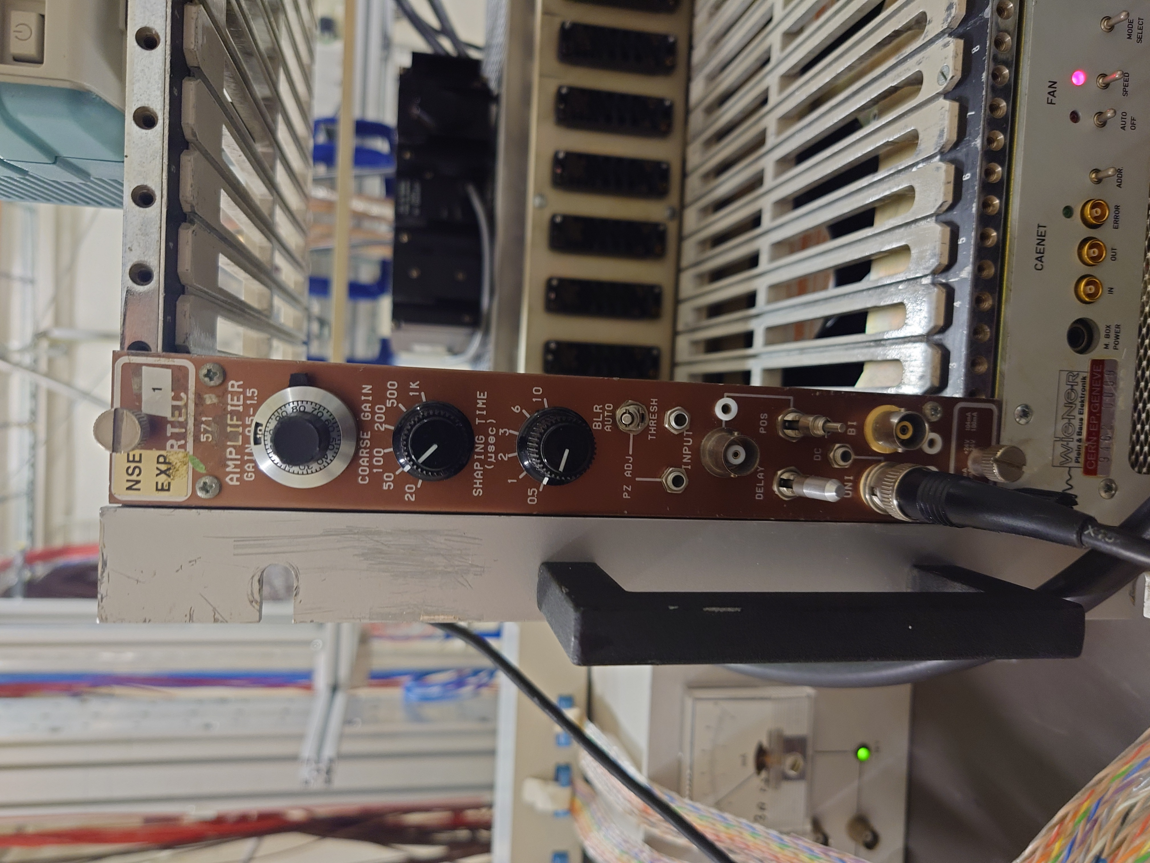
|
| Attachment 7: HV_EDET.JPG
|
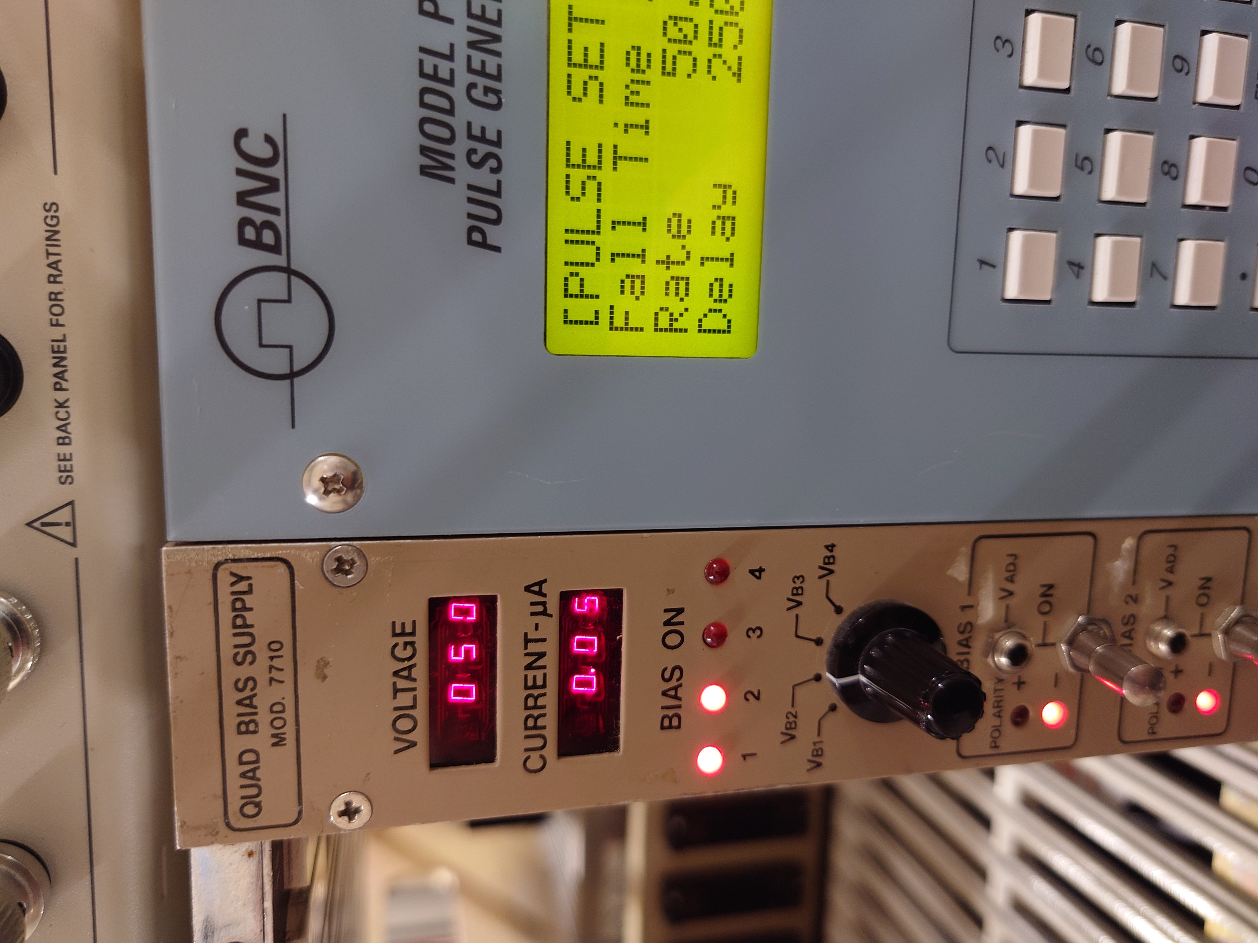
|
| Attachment 8: HV_DEED.JPG
|
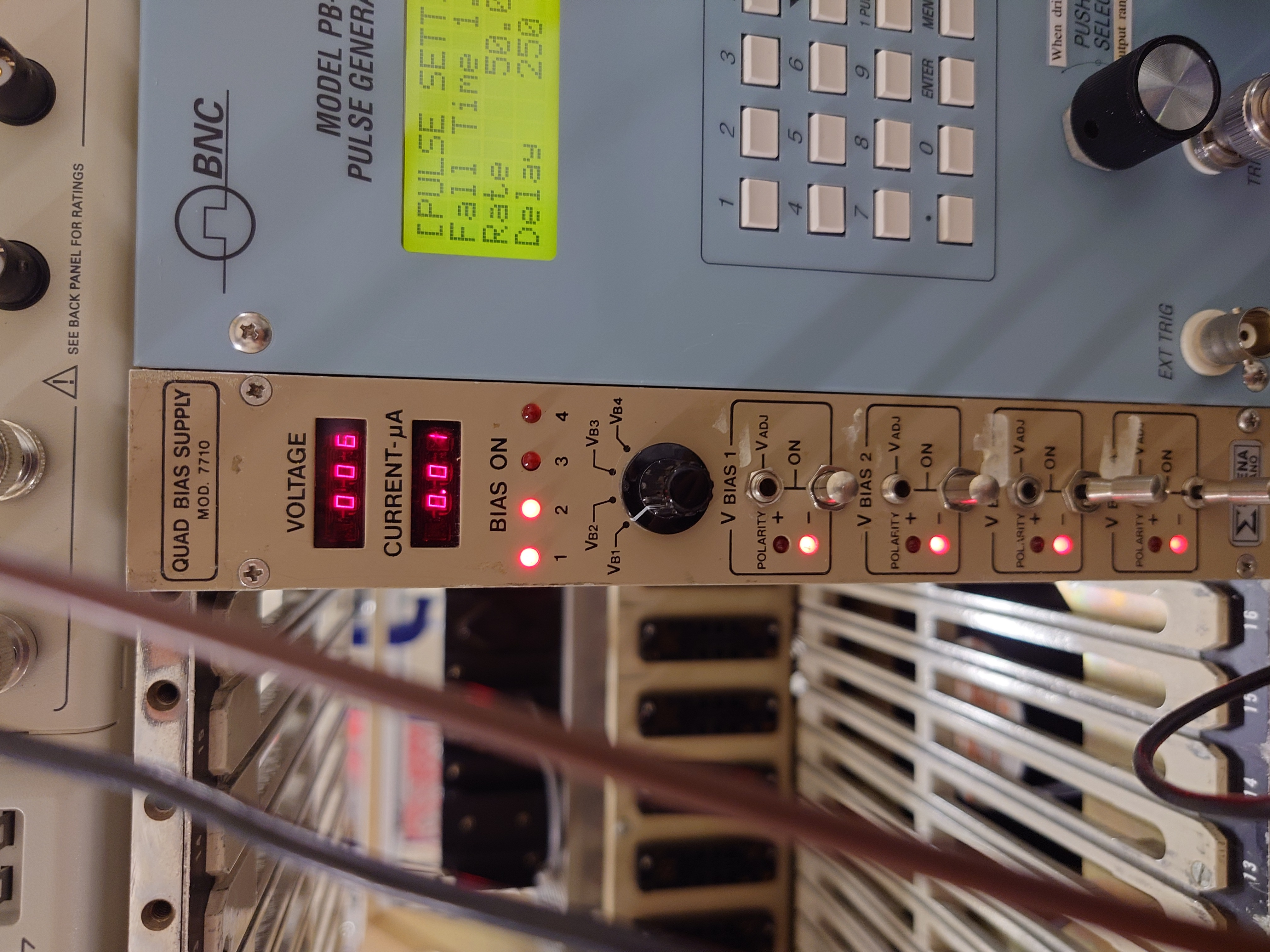
|
| Attachment 9: Pulser_Settings1.JPG
|

|
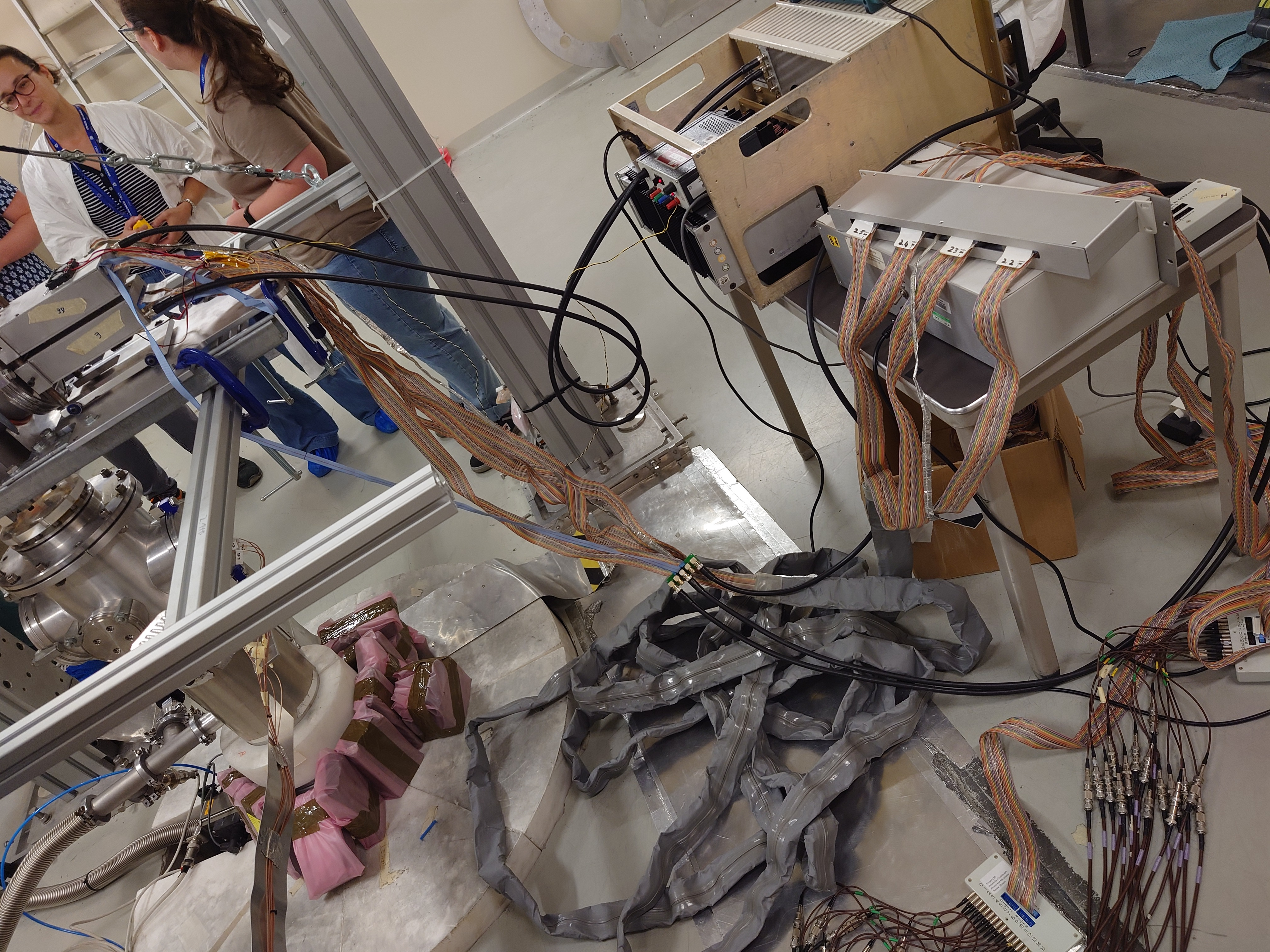
| Attachment 10: Cables_Full_View.JPG
|
|
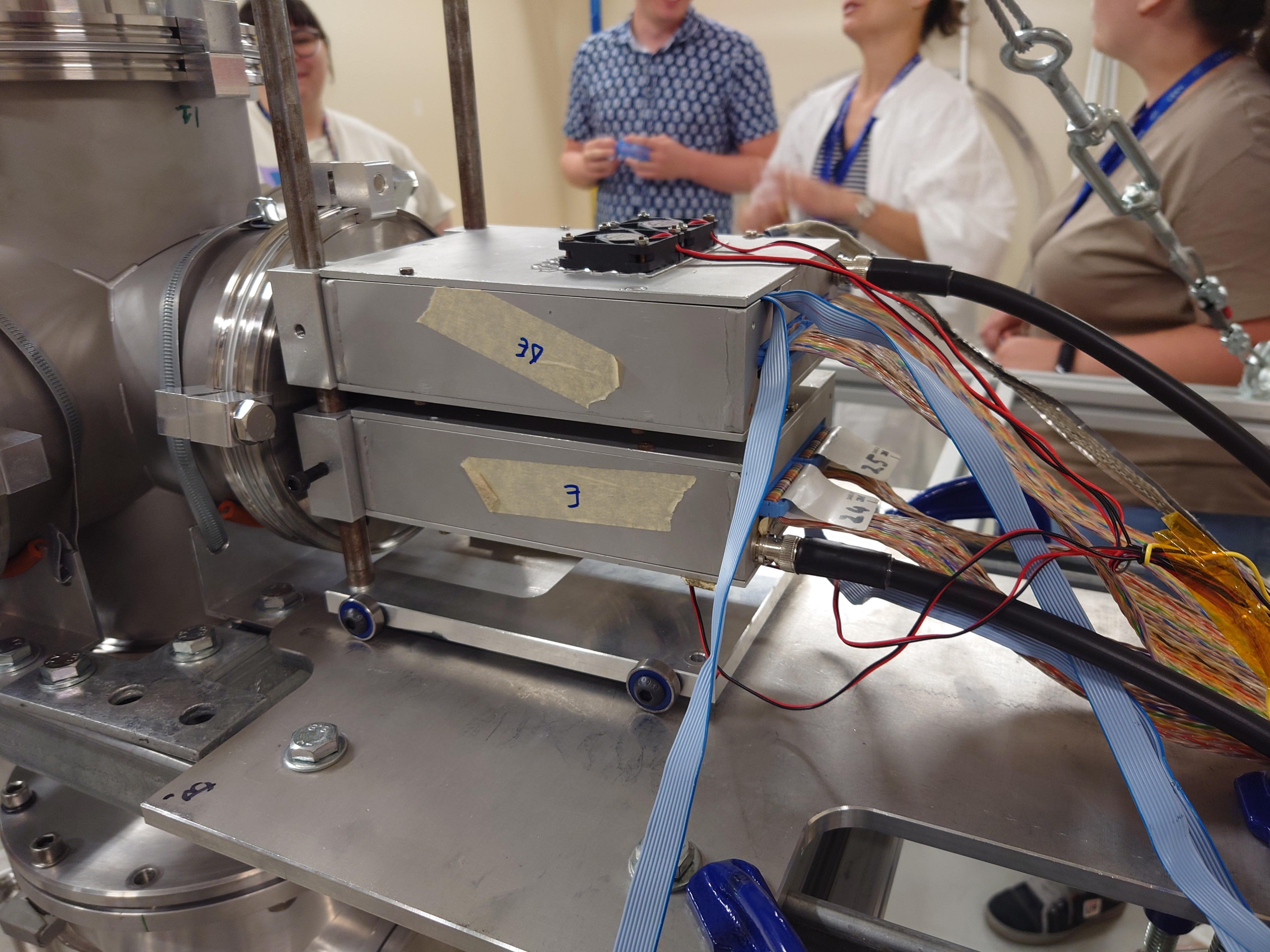
| Attachment 11: Preamp_Cables.JPG
|
|
| Attachment 12: BNC_Converters.JPG
|

|
| Attachment 13: DAQ_Cable_Connection_BNC.JPG
|

|
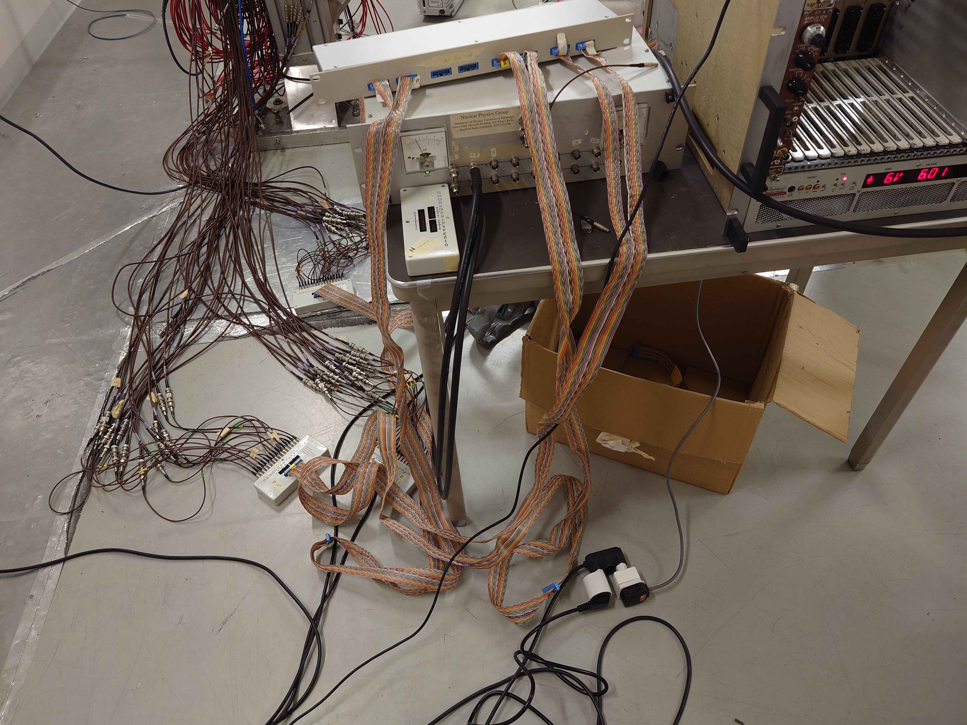
| Attachment 14: Ribbon_Cables_DAQ.JPG
|
|
| Attachment 15: Ribbon_Cables_DAQ.JPG
|

|
| Attachment 16: NIM_Setup_Full.JPG
|

|
| Attachment 17: Vacuum_Pump.JPG
|

|
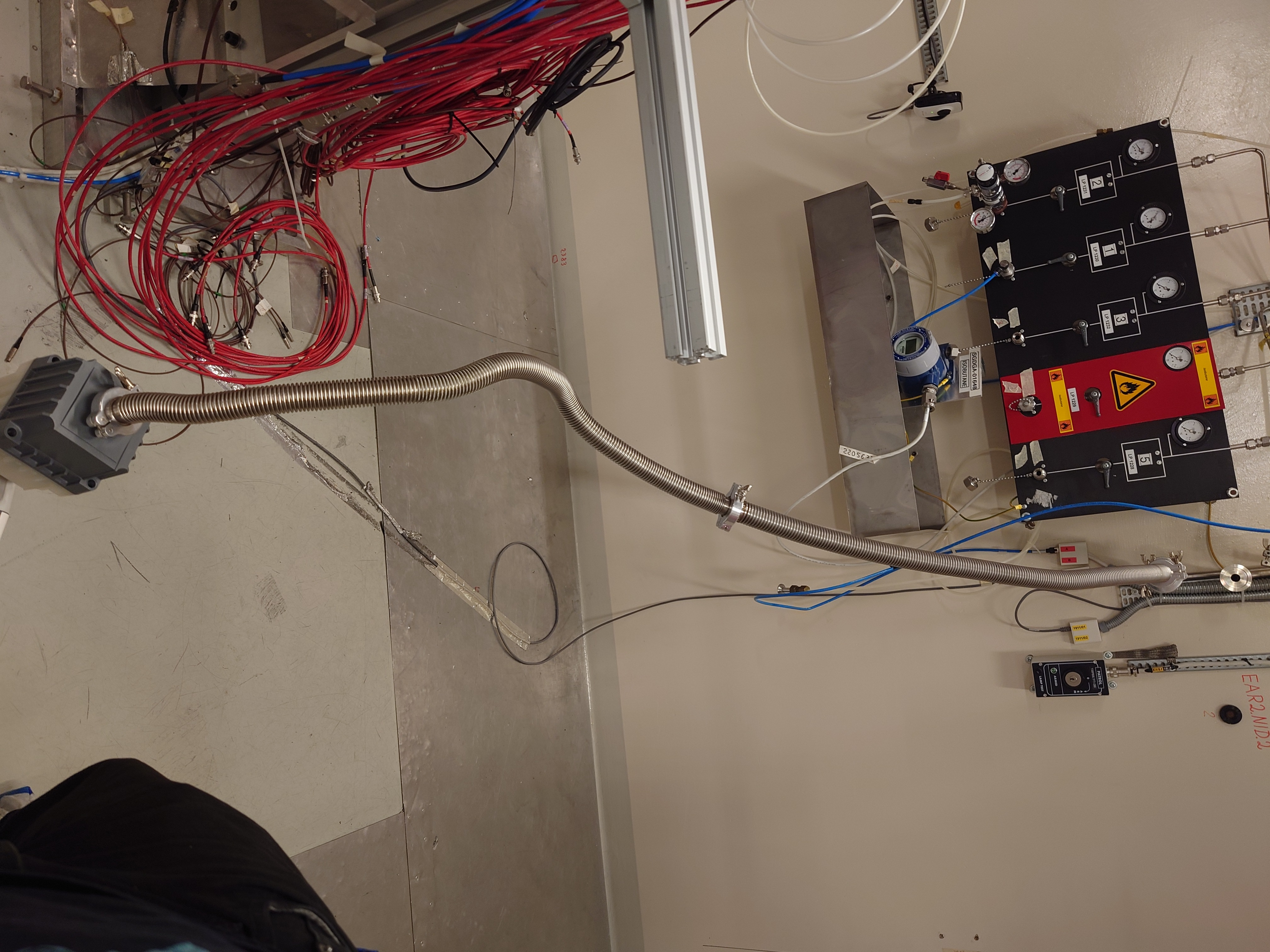
| Attachment 18: Vacuum_Pump_Exhaust.JPG
|
|
| Attachment 19: Vacuum_Pump_Attachment.JPG
|

|
| Attachment 20: Vacuum_Gauge.JPG
|
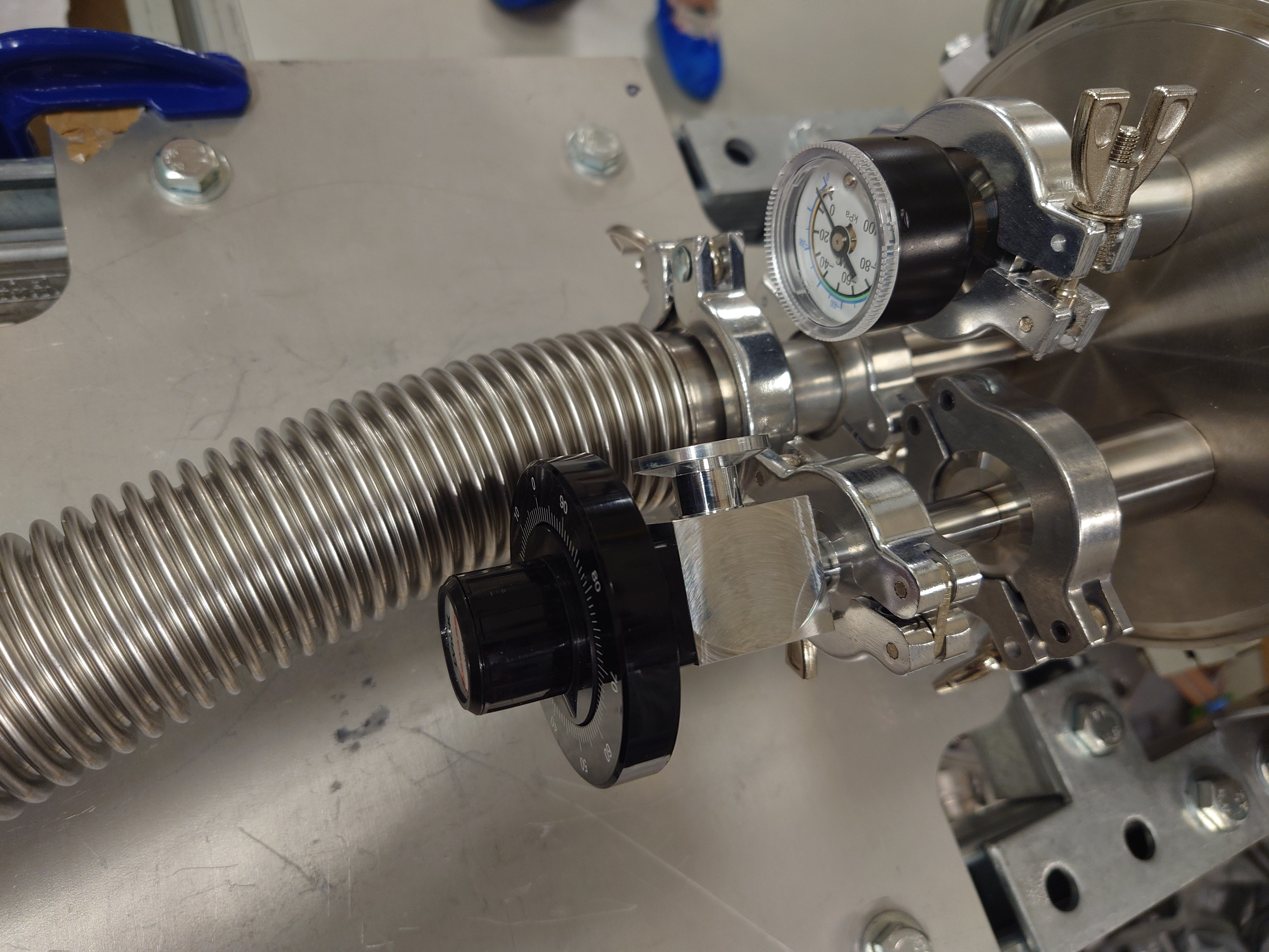
|
| Attachment 21: Vacuum_Valve_Lid.JPG
|

|
| Attachment 22: Ribbon_Cables_Back.JPG
|
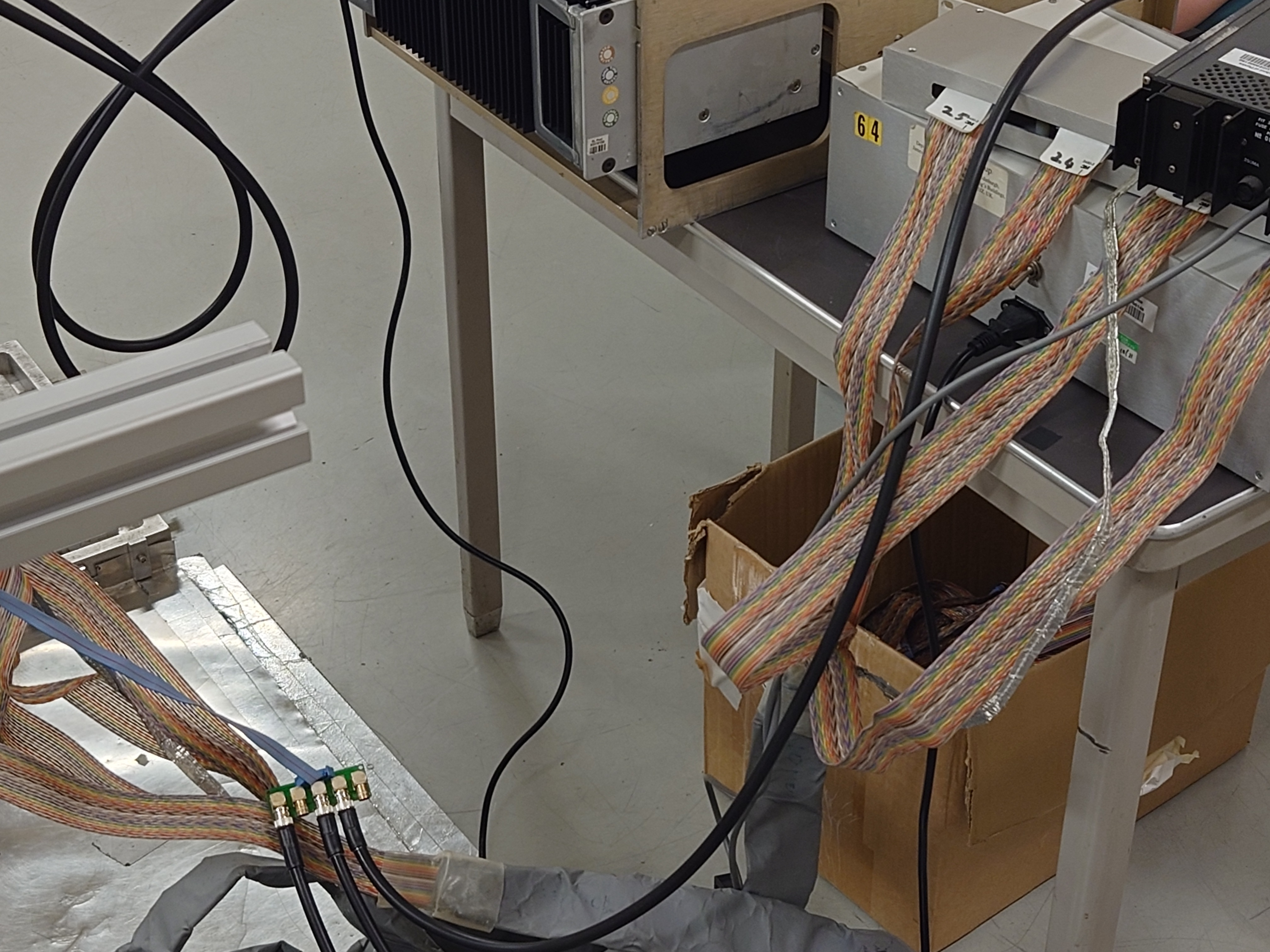
|
| Attachment 23: Ribbon_Cables.JPG
|

|
|
51
|
Thu Aug 10 11:30:32 2023 |
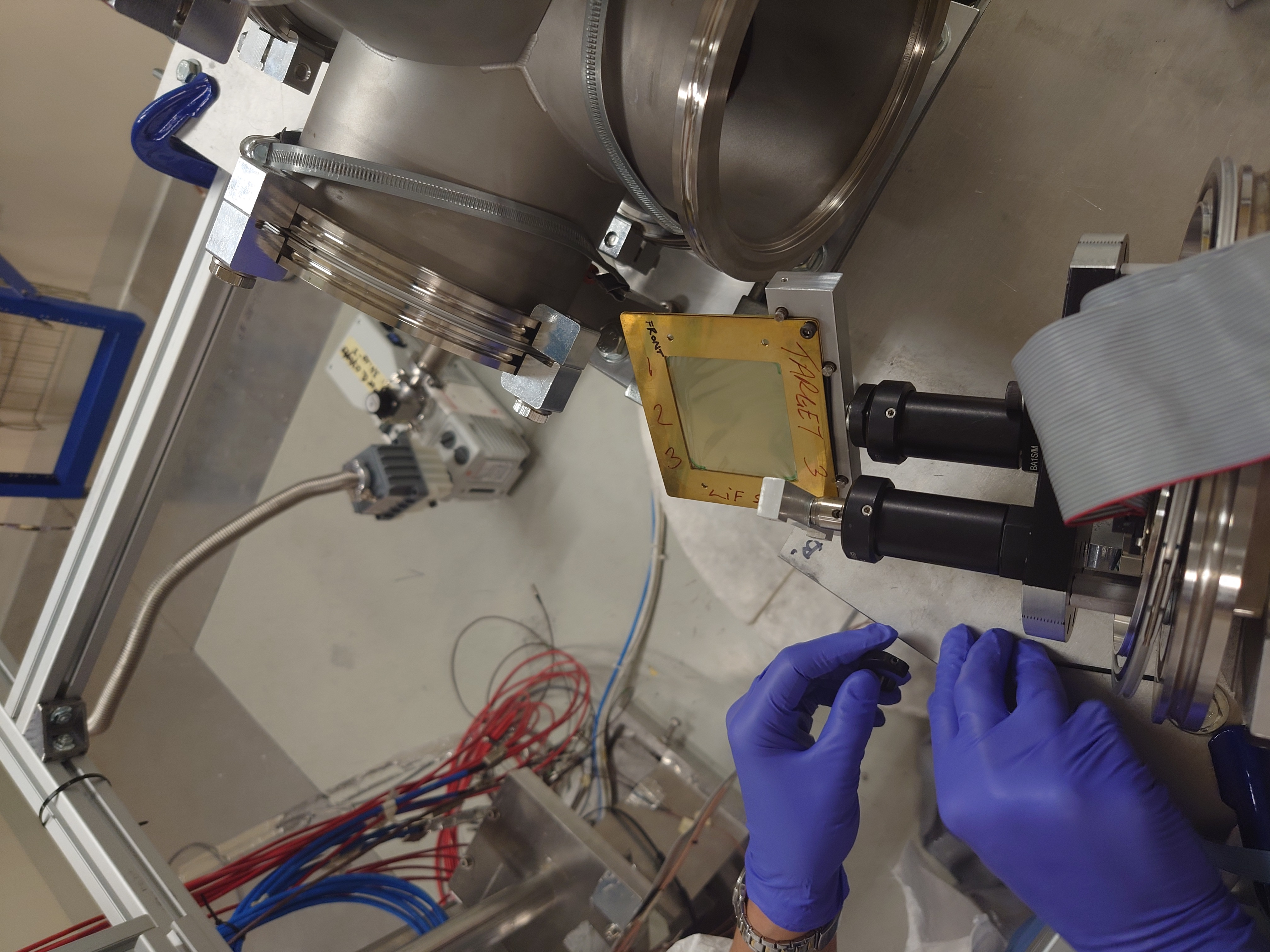
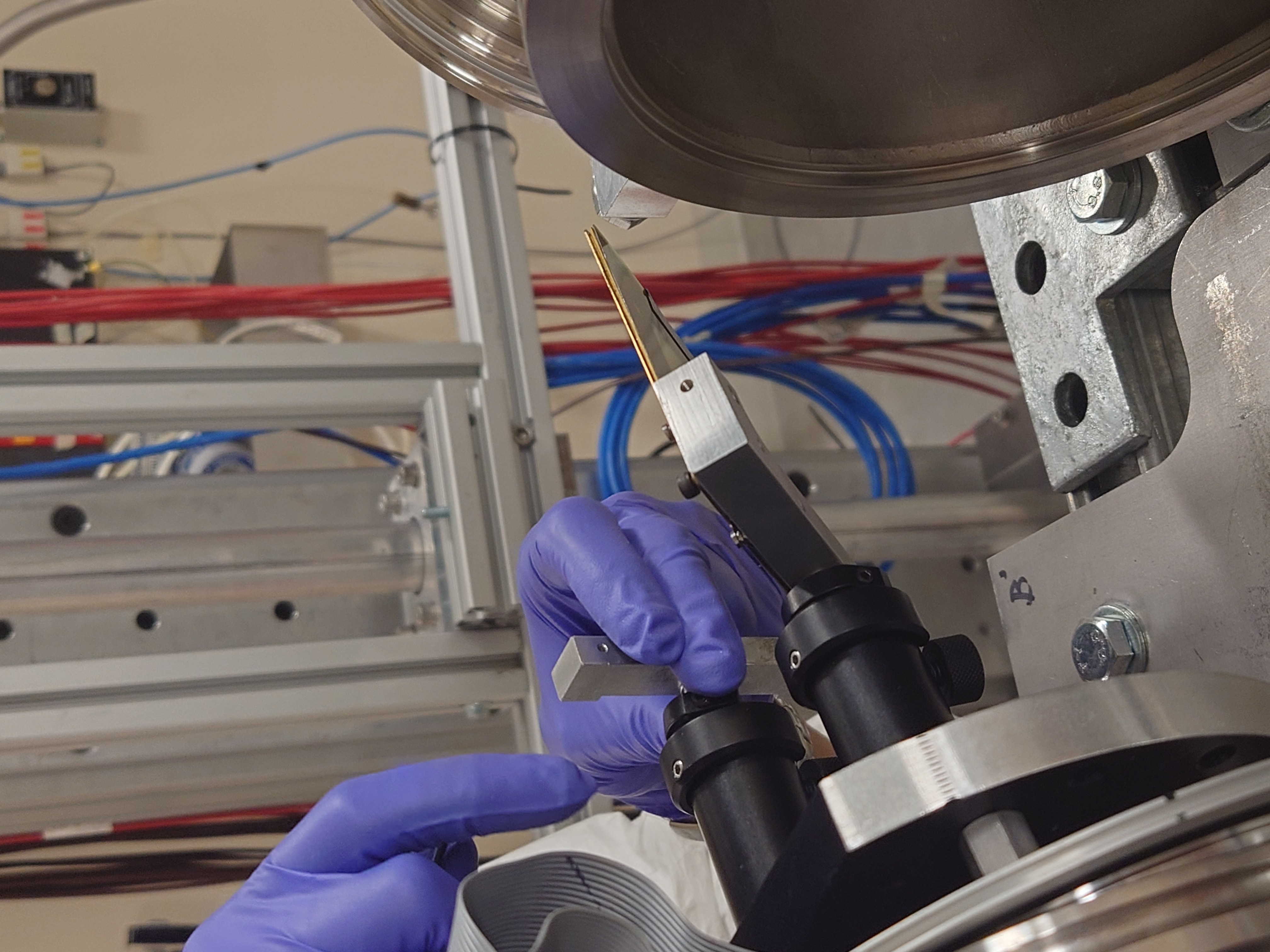
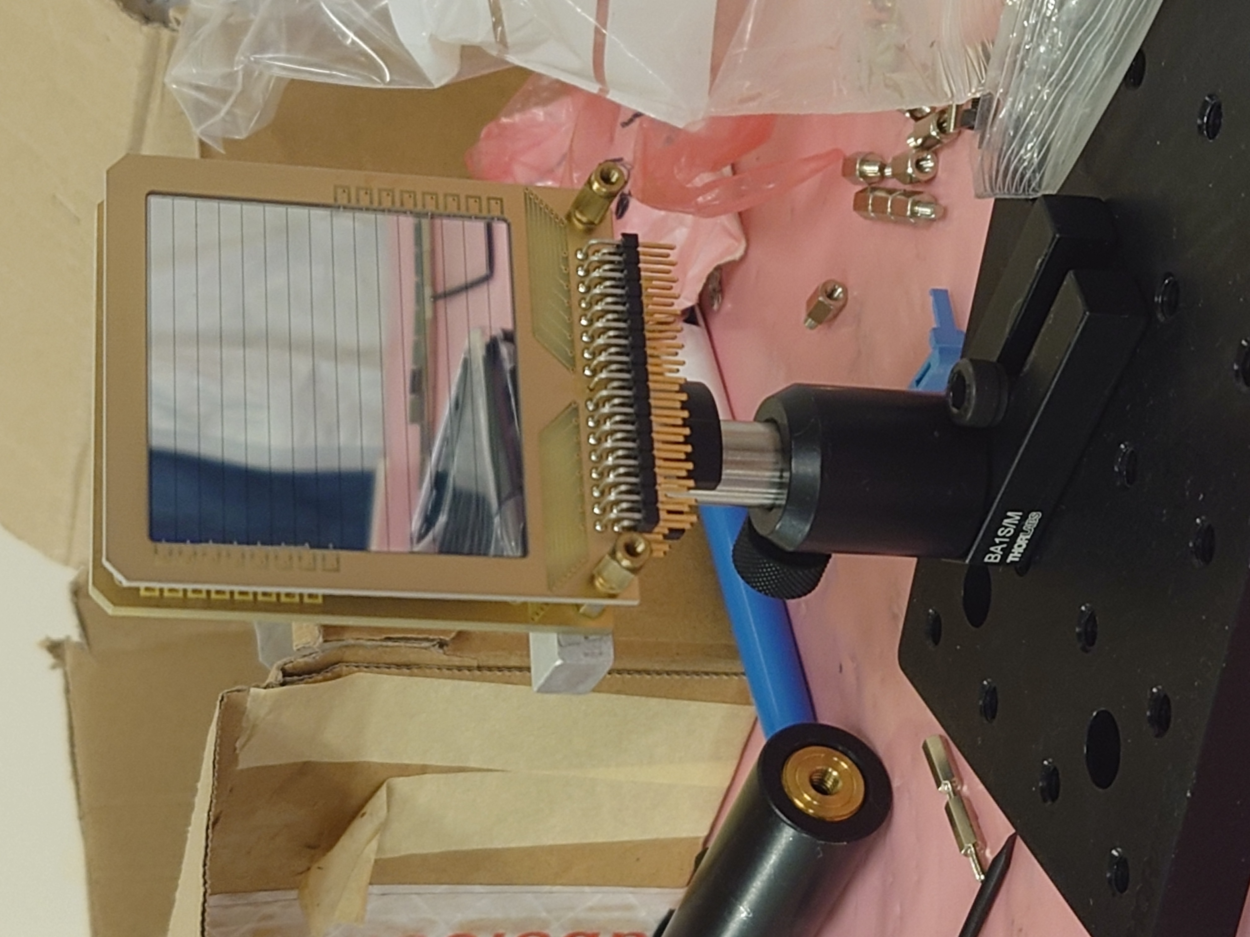
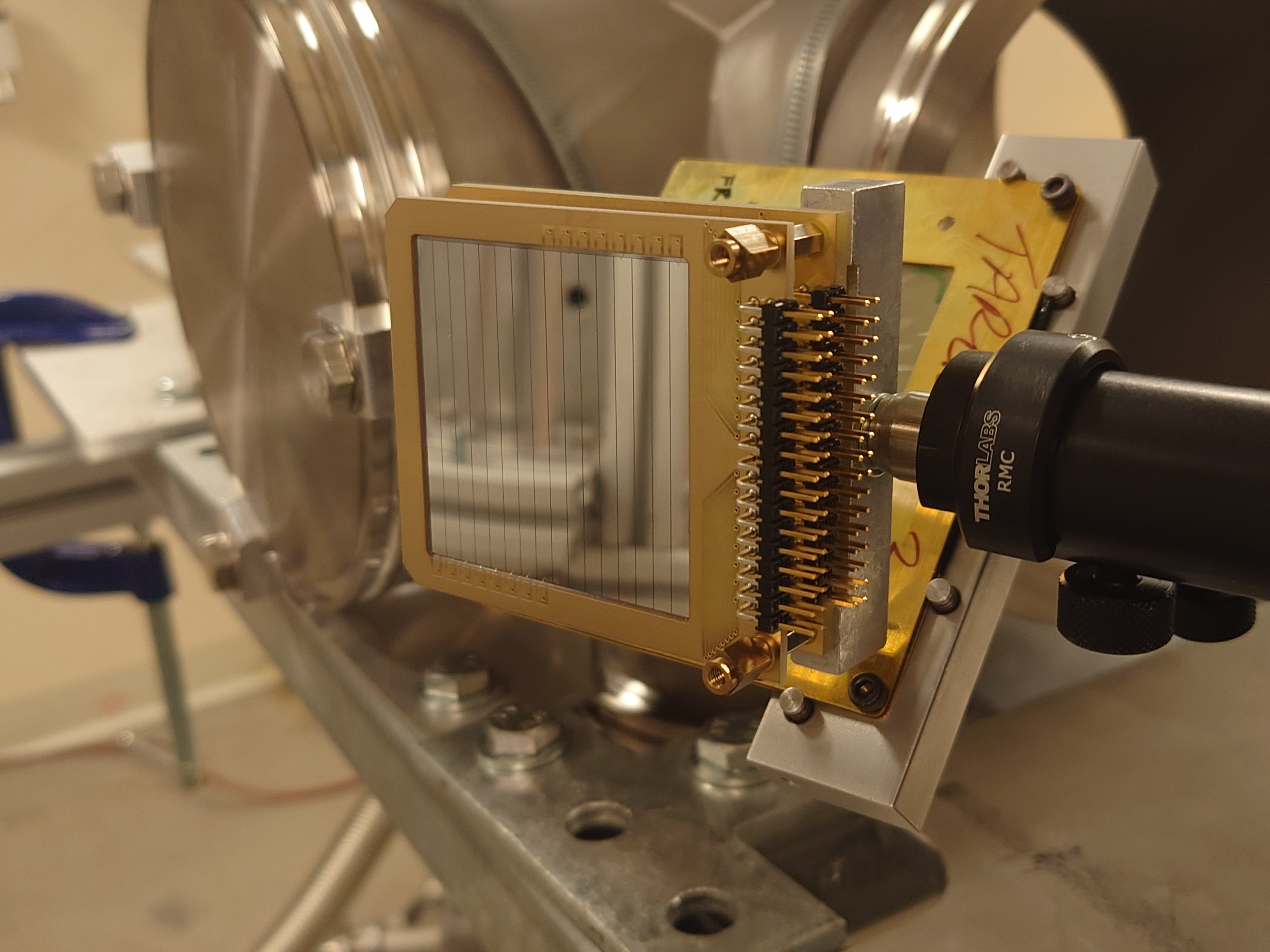
Nikolay Sosnin | Silicons and LiF3+Gafchromic Target |
|
| Attachment 1: EDET_150um_Box.JPG
|

|
| Attachment 2: EDET_150um.JPG
|

|
| Attachment 3: EDET_ID.JPG
|
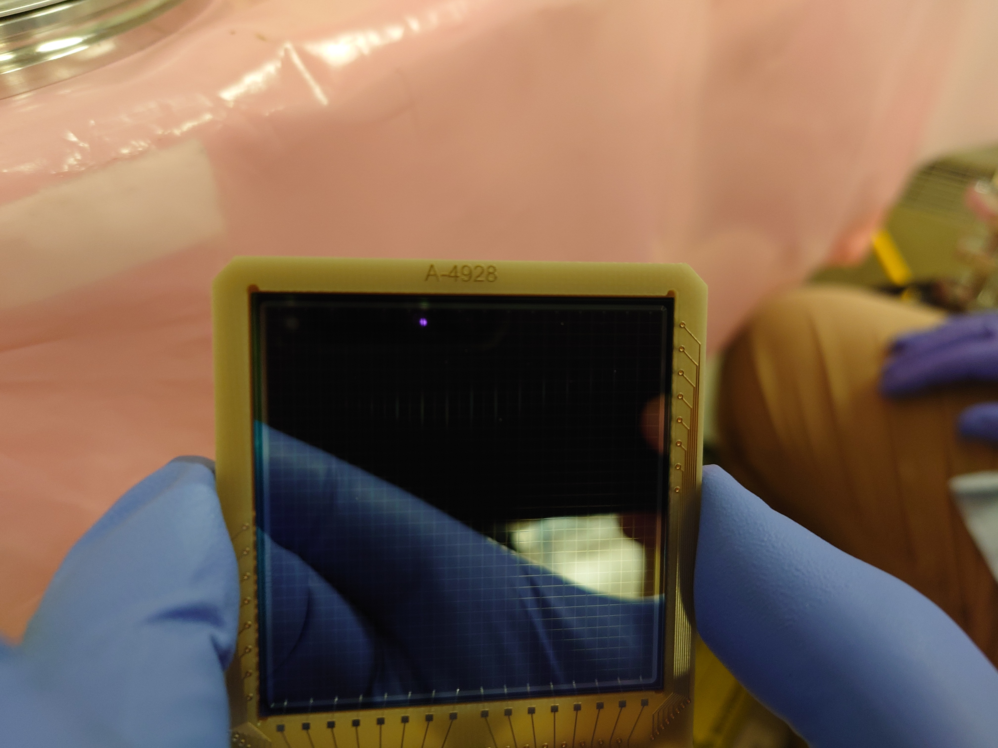
|
| Attachment 4: DEED_20um_Box.JPG
|
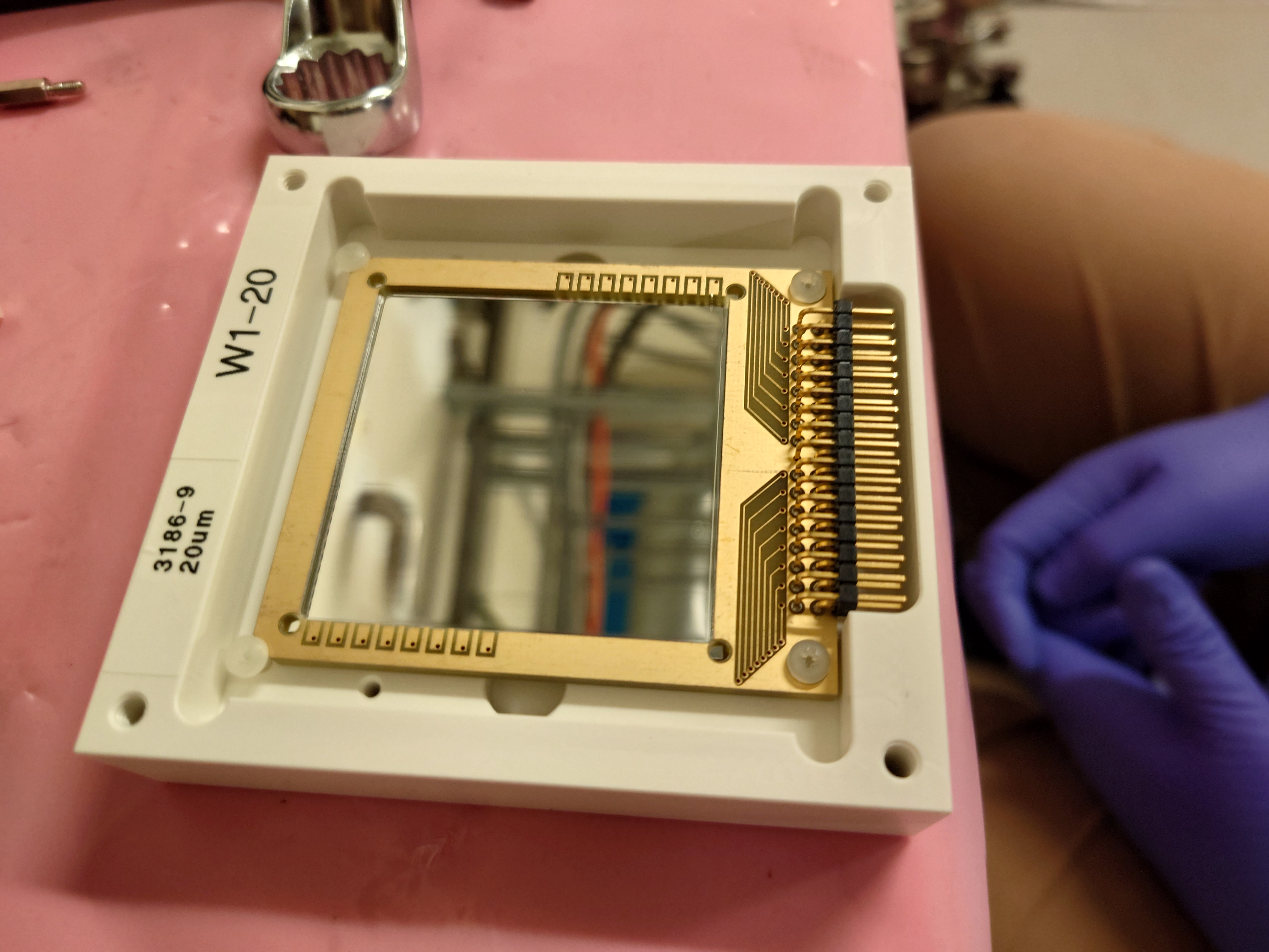
|
| Attachment 5: LiF3_Gafchrmoic_Target_Mounted.JPG
|
|
| Attachment 6: LiF3_Gafchromic_Side.JPG
|
|
| Attachment 7: LiF3_Gafchromic_Front.JPG
|

|
| Attachment 8: Detector_Mount_and_LiF3.JPG
|

|
| Attachment 9: Detectors_Mounting.JPG
|

|
| Attachment 10: Detectors_Mounted_DEED.JPG
|

|
| Attachment 11: Detectors_Mounted_EDET.JPG
|
|
| Attachment 12: Detectors_and_LiF3_Gafchrmoic_TestPosition.JPG
|

|
| Attachment 13: Detectors_and_LiF3_Gafchrmoic_TestPosition_Back.JPG
|
|
| Attachment 14: Detectors_and_LiF3_Gafchrmoic_TestPosition_Below.JPG
|
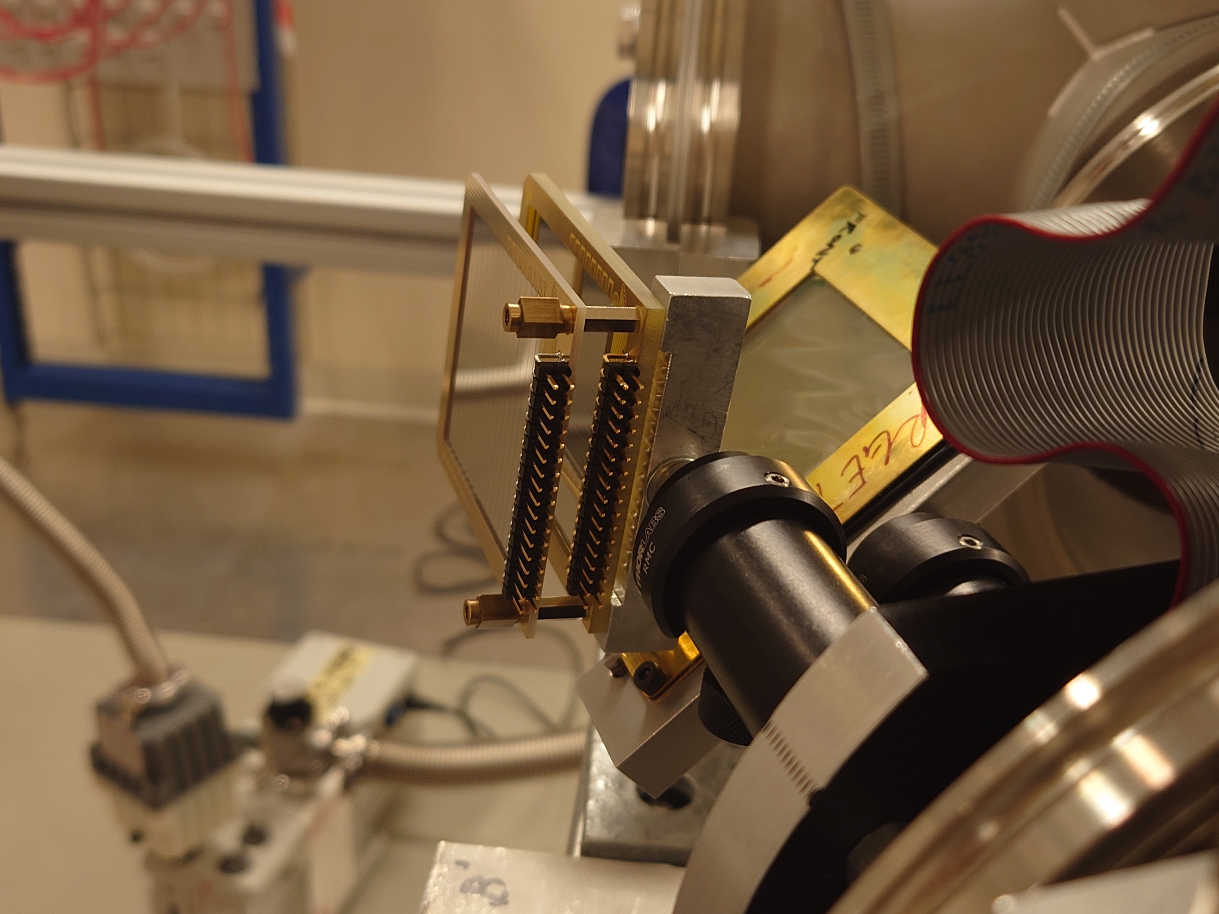
|
| Attachment 15: Detectors_and_LiF3_Gafchrmoic_TestPosition_Above.JPG
|
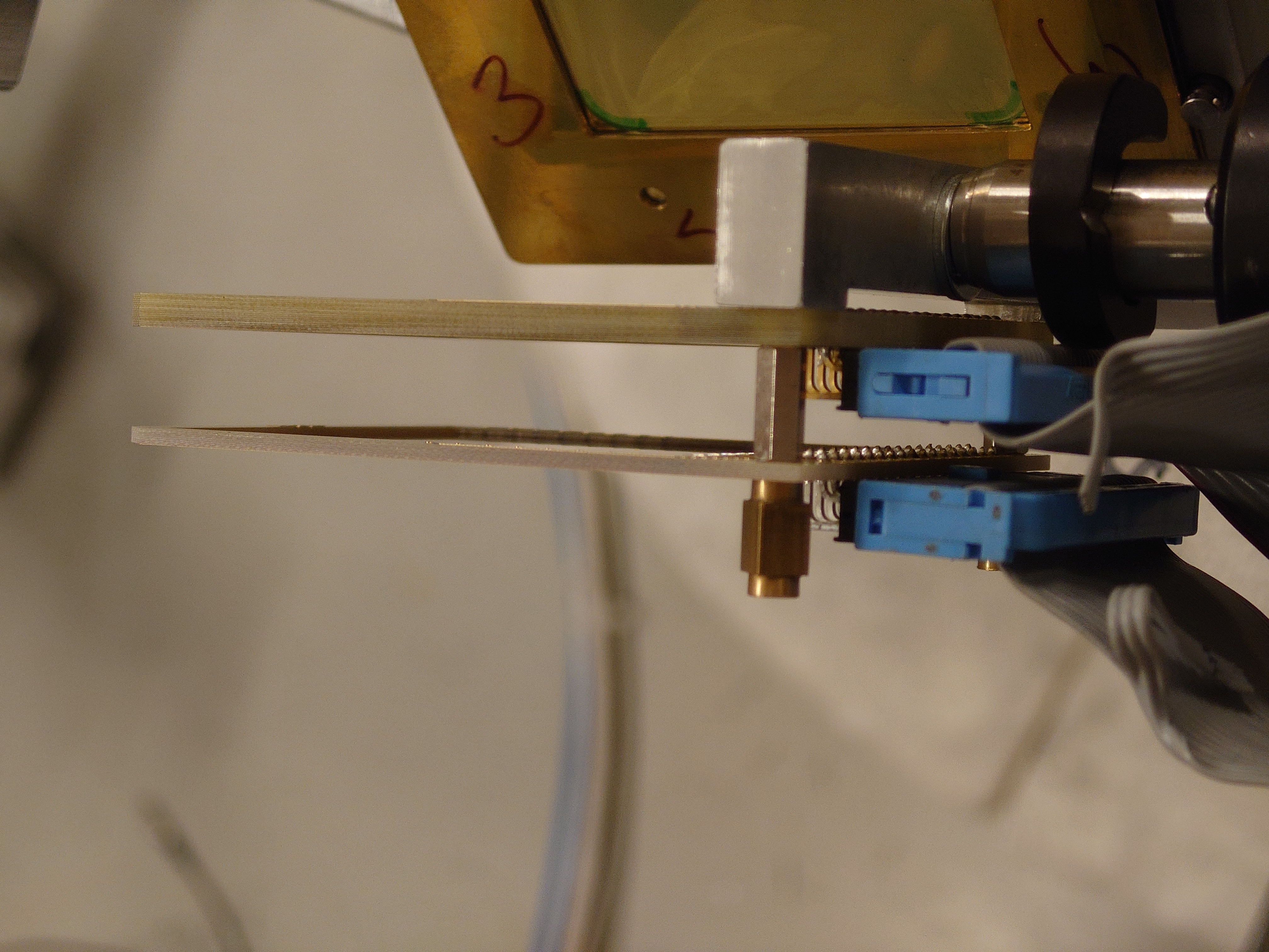
|
| Attachment 16: Detectors_and_LiF3_Gafchrmoic_TestPosition_Tilt.JPG
|
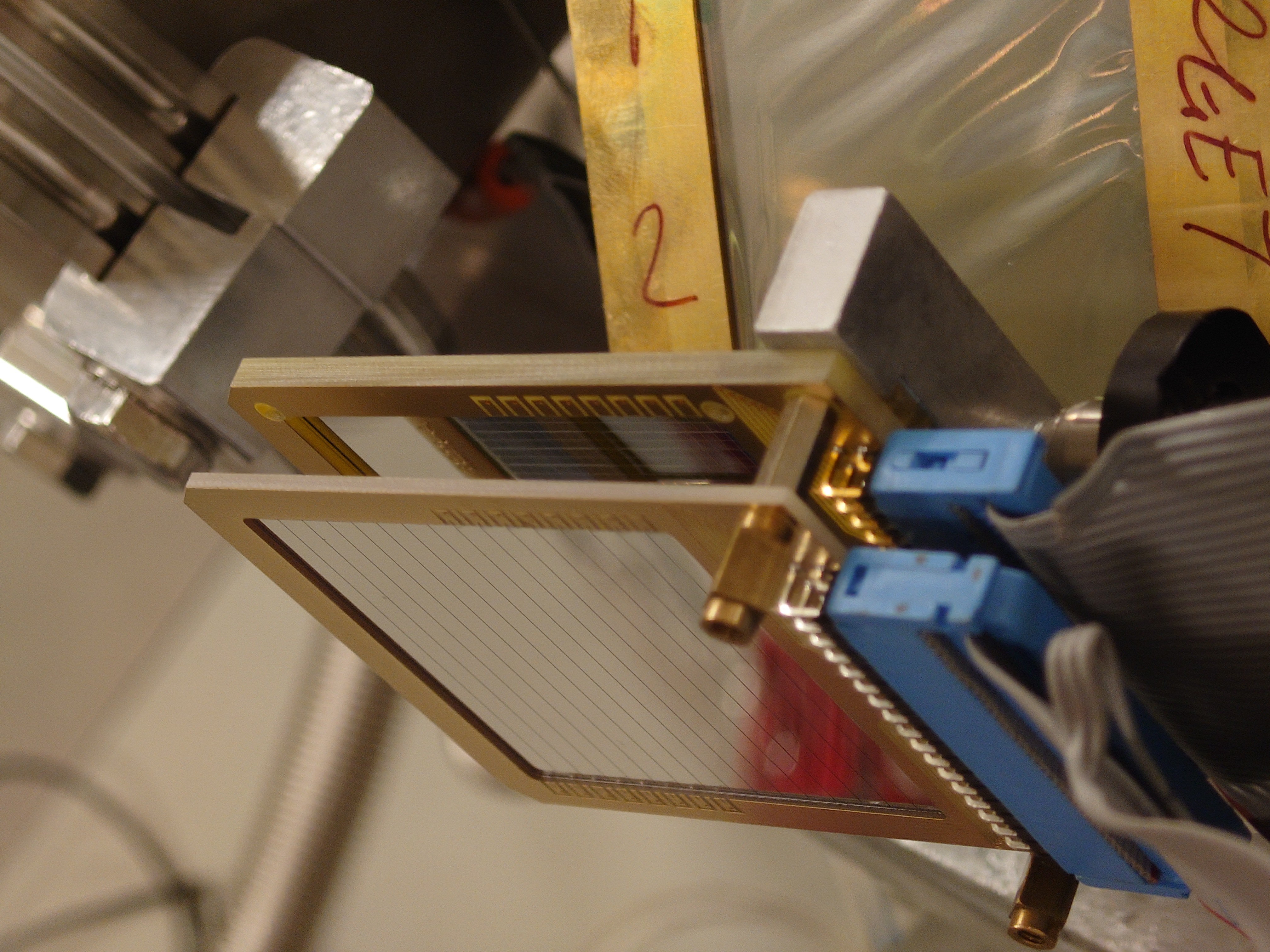
|
| Attachment 17: Detectors_and_LiF3_Gafchrmoic_TestPosition_Front.JPG
|
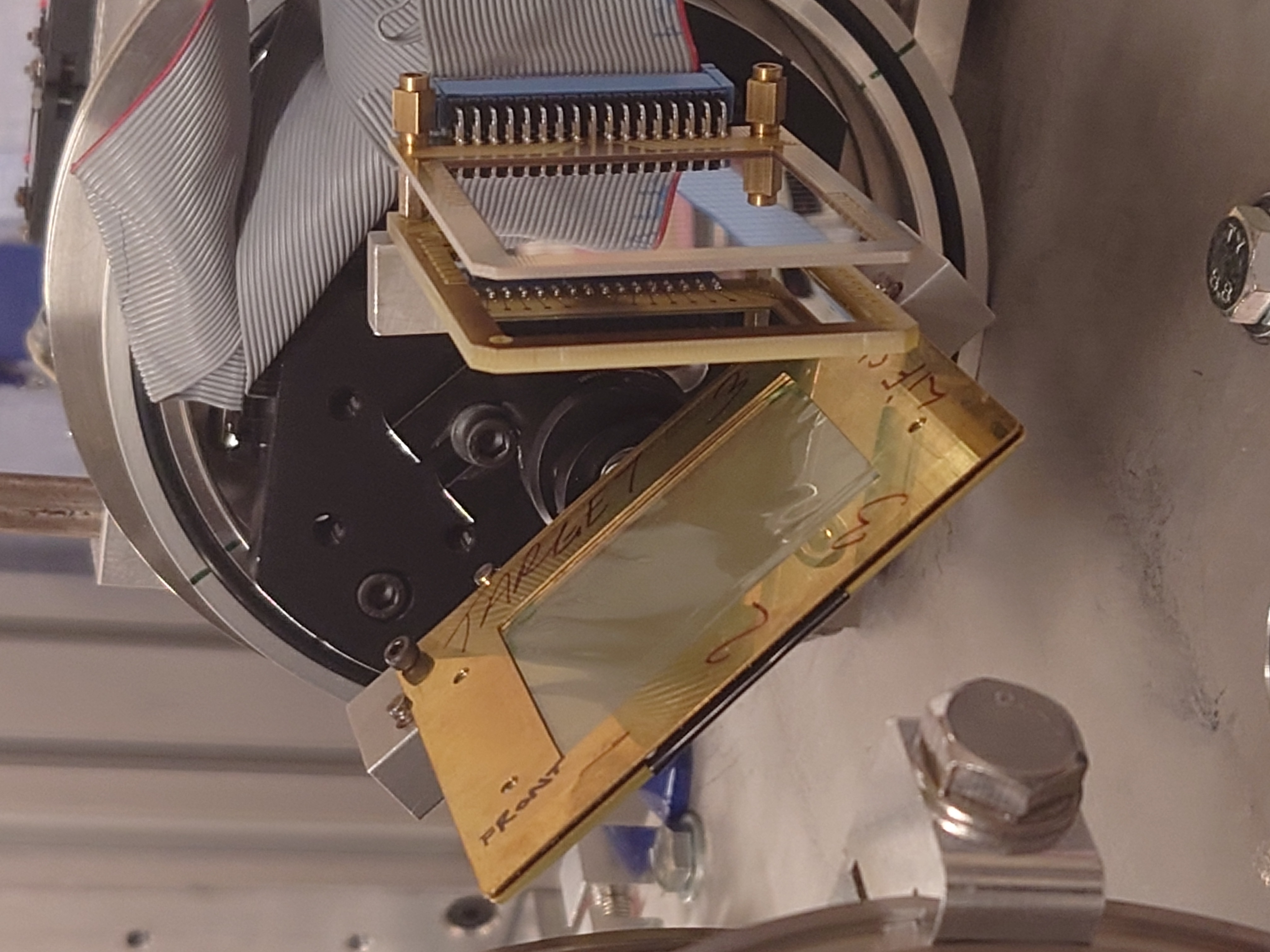
|
| Attachment 18: Assembly_Insert.JPG
|
|