| ID |
Date |
Author |
Subject |
|
547
|
Thu Mar 30 16:12:21 2017 |
DK, OH, CG | Friday, March 31 run status |
00:11 BigRIPS has started a new run at 00:10:42 run 0165.
      AIDA subrun R16_357 was about halfway (~1 GB) at 00:11.
      BRIKEN run 21 ( so-called 170331_0012_Mg40 )

      Check clock status: FEE64 module nnaida1 global clocks failed, 6 [ as usual, and it is set to ch 2 ]
      ADC calib all pass
      Clock timestamp, passed
      Sync counter error, passed
      Sync pulses all consistently near 3 x 10^7
      Memory info from Linux FEE64 all around 35k to < 40k

      Sync check on the BRIKEN terminal is looking all consistent to me.

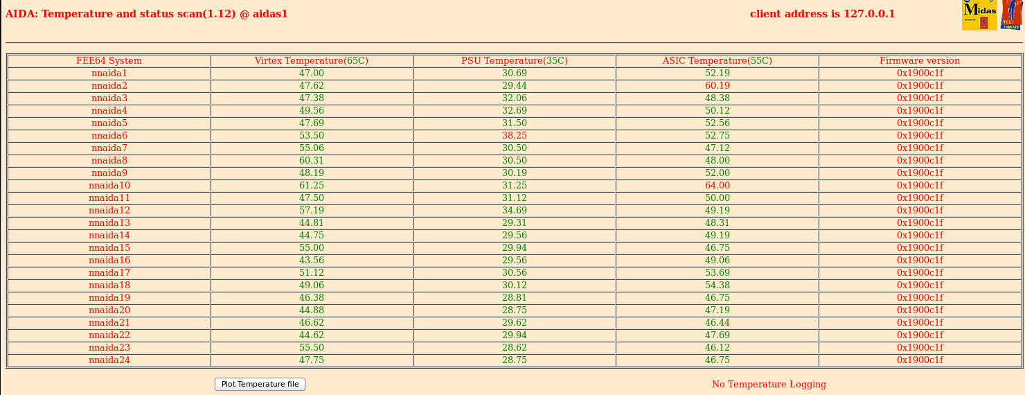
      Temperatures are seen as attachment 1, temps_31_a.png
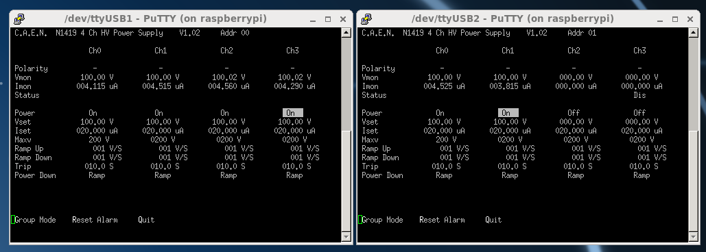
      Biases and leak currents seen as attachment 2, bias_31_a.png

      As for what I've checked then we continue on in what appears to be a stable condition.

01:12 I can see BigRIPS team at their DAQ PC about to change the run.
      2017-03-31 01:12:24 BigRIPS run 0166 starts
      AIDA subrun R16_372 is 75% finished at 1:12
      BRIKEN run 22, [ 170331_0114_Mg40 ] -- timestamp beginning at 1:14 means they are almost exactly at the
beginning of AIDA R16_373

      Check clock status, ibid to above
      Check ADC calib, ibid
      Check ASIC clock timestamp, ibid
      Check sync errors, ibid
      Check sync pulses, 3.2 x 10^7 consistently
      Check FEE64 memory, 36k to 37k.

      Sync check at BRIKEN is still running and shows the clocks are lined up.

      Continue.


02:10 BigRIPS begins a new run, number 0167
      AIDA subrun R16_386 finished at 2:10, so BigRIPS 0167 should correspond nicely with the start of AIDA R16_387
      BRIKEN run number 23 [ 170331_0214_Mg40 ]

      All six (6) system wide checks were performed.  The situation remains stable as above.

03:13 BigRIPS starts a new run at 3:12:51
      AIDA R16_402 is about 50% complete at 3:13
      BRIKEN 24 [ 170331_0314_Mg40 ]

      All system-wide checks are passed.  Number of sync pulses is ~3.7 x 10^7

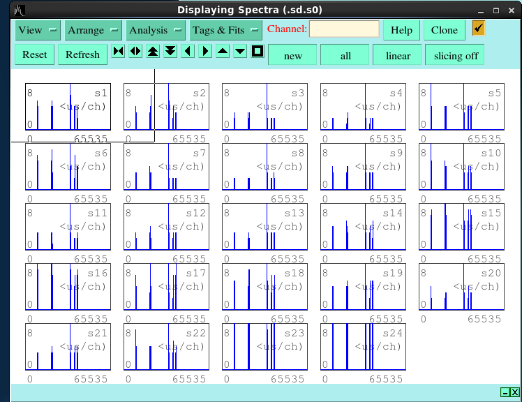
03:33 Bored so here's some spectra, attachment 3 as pulses_31_b.png.  It looks good.

04:10 BigRIPS run 0169 began at 2017-03-31 04:09:50
     AIDA is R16_416 50% though at this time.
     BRIKEN 25 [ 170331_0413_Mg40 ]

     All checks passed.  I'm not just writing it, but they were performed :)

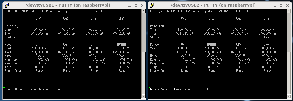
     See attachment 4 for bias.  had screencapped temp but forgot to update so it was just a clone of attachment 1 (this
was noticed at 8:07)

04:58 Beam operators called.  They stopped the beam so they can exchange the carbon stripper foil.
     AIDA R16_428 was 25% through at 4:58.

05:02 R16_429 is at 600 MB I hear the chime to indicate the beam is back
     BigRIPS 2017-03-31 05:02:57 run 0170 is started
     BRIKEN run 27 [ 170331_0504_Mg40 ] -- NB: Run 26 was junk (some mistake)

     All six (6) system wide checks are a go.  3.7 x 10^7 is the sync pulse count.
     Continue.

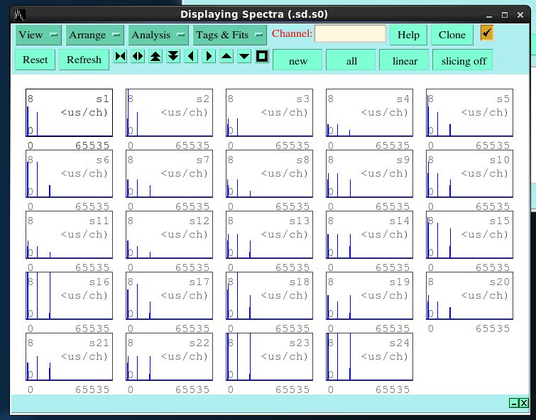
05:12 I show you the AIDA look good in attachment 5 spec_31_c.png

06:10 still waiting on BigRIPS to notice what time it is.

06:14 BRIKEN sends the resync.  (this note is written at 7:11..see below)

06:16 R16_447 Jorge realizes there are no neutrons in BRIKEN, and we realize the second beam physicist is on the phone.

06:29 Beam physicists hang up the phone...2017-03-31 06:29:30 BigRIPS run 0171
     AIDA run R16_451 is almost exactly beginning at 6:29
     BRIKEN run number 28
     The system wide checks are consistent as before
          FEE64 module nnaida1 global clocks failed, 6
          Check sync pulses sees 3.9 x 10^7

06:36 - I asked the BigRIPS team the situation.  Basically, they calibrate the faraday cup and also three plastic
scints near F0 (primary target) for calibrartion (cross section estimation) purposes.
     So it seems in this time THEY have the beam yet we do not because it is not reaching all the way to F11 the
entire time.
     Though I do not want to bother the operators with too many questions, it can be that parts of BigRIPS run 0170
near the end will not correlate with our data.

07:11 - I had not caught that BRIKEN sent the resync.  It was confirmed that it was the only resync issued tonight.
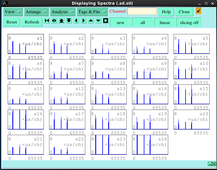
     Please see the attachment 6 "spec_31_d.png", though I'm not sure it would be useful

07:47 Not sure the situation.  Beam physicists were near their DAQ PC for a bit, then on the phone, but their run has not
restart.
     AIDA run R16_469 at this time, just to note.

07:57 2017-03-31 07:55:33 BigRIPS run 0177 is started.  Evidently run 0176 is skipped somehow.
     AIDA R16_471 was at 1.9 GB at 7:57 so probably it mostly correlates with the start of the BigRIPS run.
     BRIKEN run number 29 (?) [ 170331_0758_Mg40 ]

     [8:15 - confirmed the problem with beam physicists was a DAQ issue.  Thus BigRIPS run 0172 is junk, and they took
some time to resolve their issue.]

     System-wide checks look normal.  4 x 10^7 sync pulses
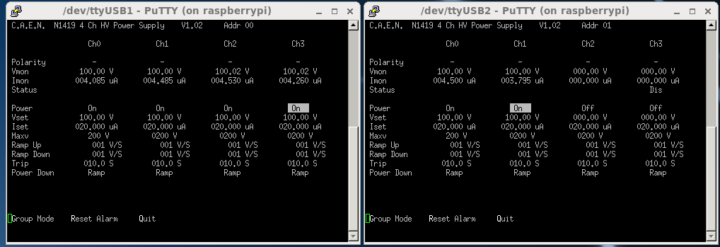
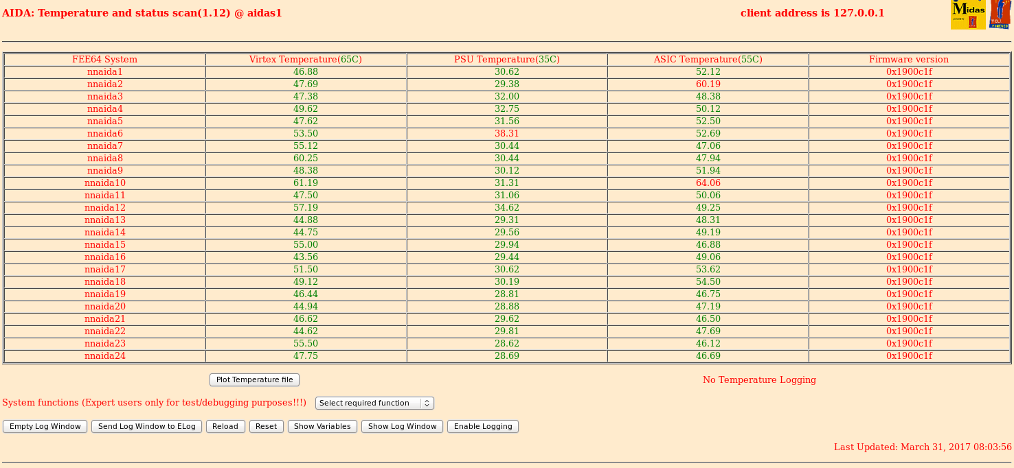
     Attachments 7 and 8 have bias and temp ("bias_31_e.png" and "temp_31_e.png")

08:07 When doing the temperature this time, I realized that an early temperature "temp_31_b" was just a clone of
"temp_31_a" as I forgot to refresh.  Now the attachment numbering changes as I delete it, and the elog is updated to
correctly reflect the new ordering.  I should be more careful.

08:56 BigRiips start run 0174
      End of AIDA file R16_485
      BRIKEN file 31
      System wide checks all ok *except* nnaida1 fails global clocks 6
      ASIC check all ok

09:44 BigRips stopping the beam
      Half way through AIDA file R16_498

09:57 System wide checks all ok *except* nnaida1 fails global clocks 6

10:01 BigRips start run 0175
      Start of AIDA file R16_502
      BRIKEN file 32

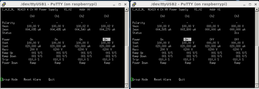
10:11 Biases and leakage currents ok (See attachment 9)

10:19 BigRips start run 0176
      End of AIDA file R16_506

10:23 BRIKEN start file 33
      AIDA on file R16_507

11:21 BigRips start run 0177
      End of AIDA file R16_521
      BRIKEN start file 34
      System wide checks all ok *except* nnaida1 fails global clocks 6
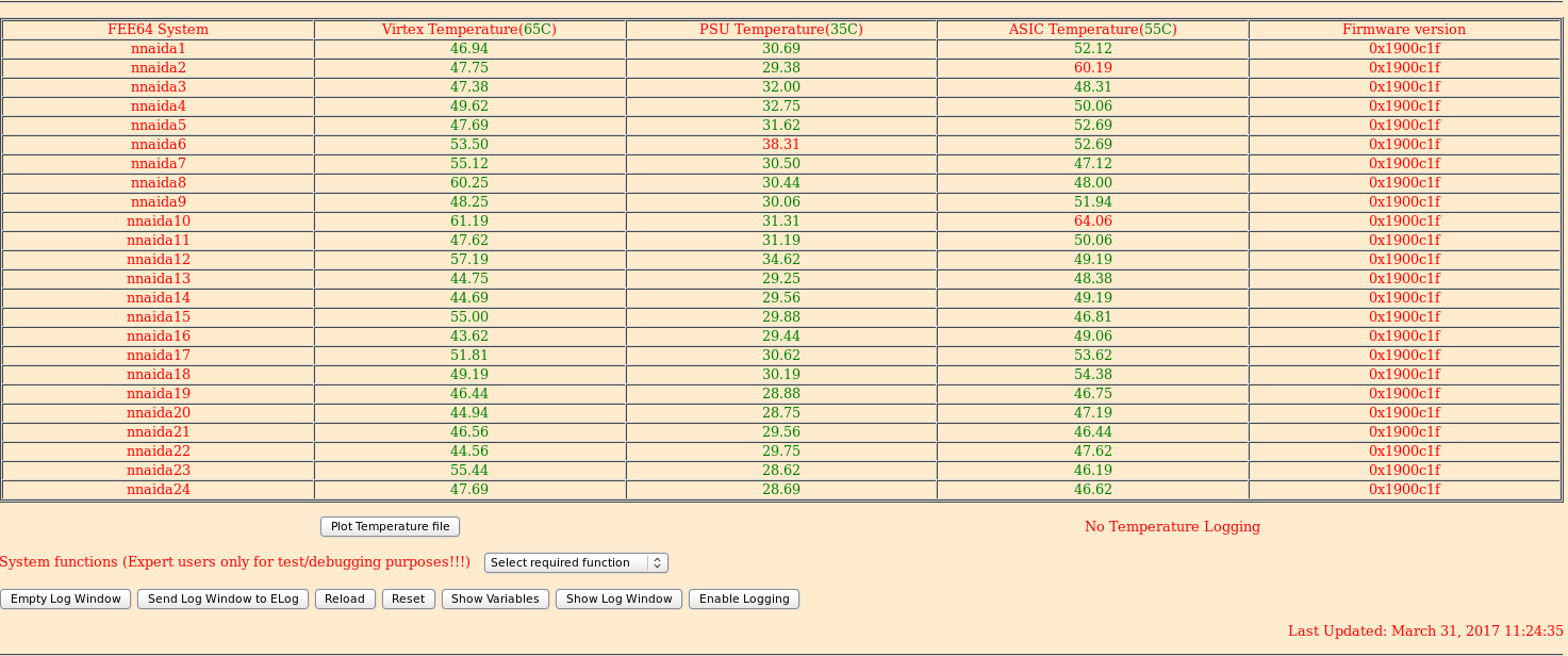
      Temperatures ok (See attachment 10)

12:21 BigRips start run 0178
      AIDA file end of R16_536
      BRIKEN start run file 35
      System wide checks all ok *except* nnaida1 fails global clocks 6
      ASIC load check ok

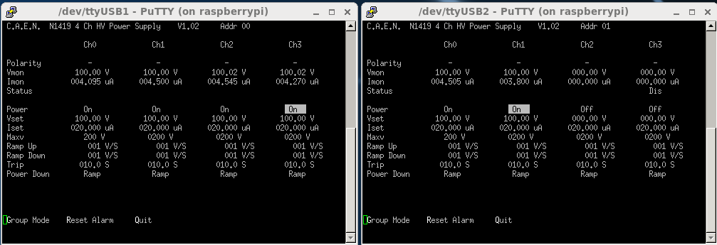
12:43 Biases and leakages are ok (See attachment 11)

13:20 BigRips run 0179
      AIDA halfway through R16_551
      BRIKEN start run file 36
      System wide checks all ok *except* nnaida1 fails global clocks 6

13:39 bigRips run 0180
      AIDA file end of R16_555

14:44 System wide checks all ok *except* nnaida1 fails global clocks 6
      ASIC load check ok
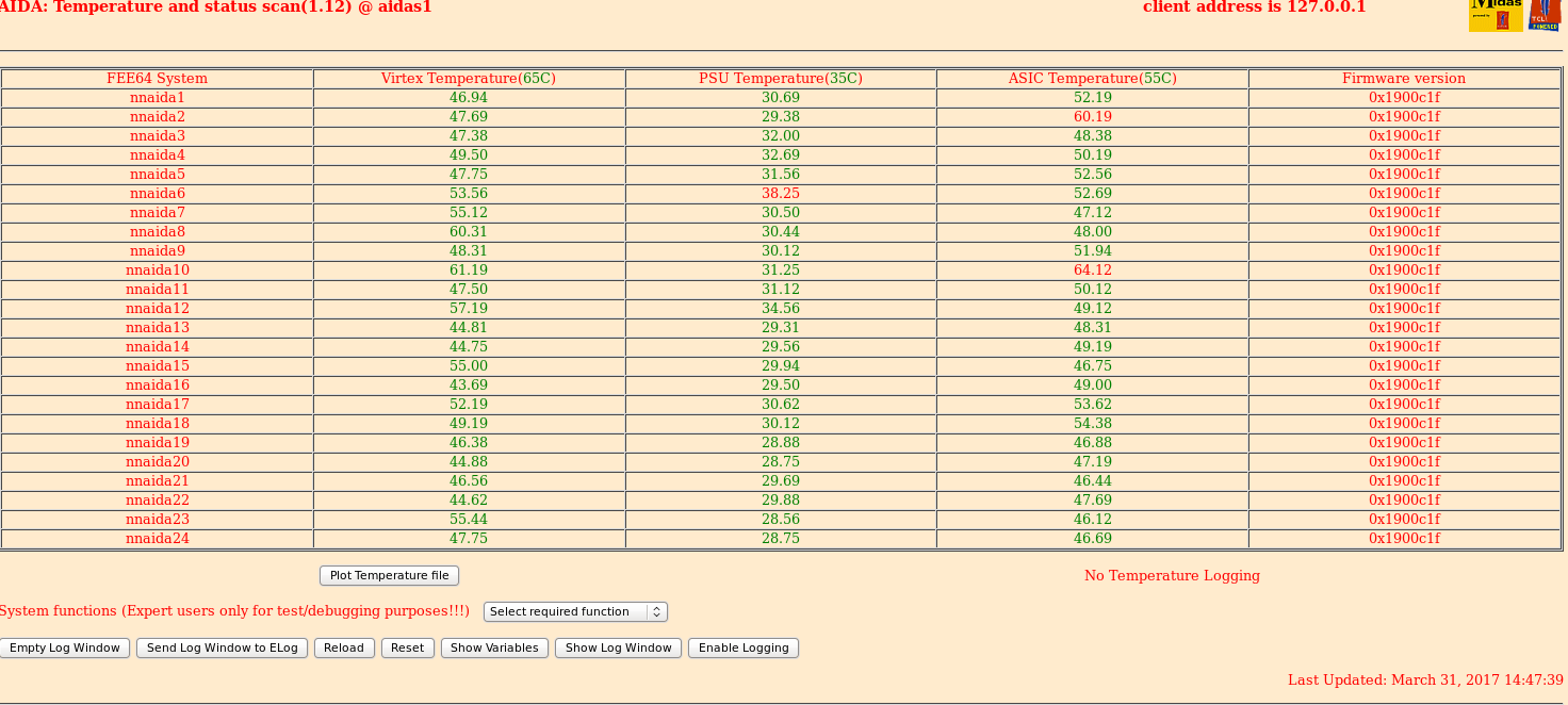
      Temperatures all ok (See attachment 12)
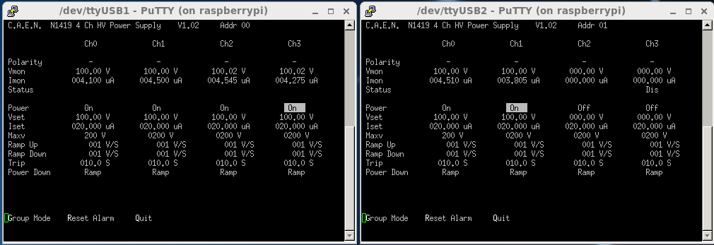
      Biases and leakage currents ok (see attachment 13)

15:14 BigRips is stopped
      AIDA file R16_579

15:16 BigRips started run 0181
      AIDA file  end of R16_579

15:24 BRIKEN starts file 37
      AIDA file 3/4 of R16_581

16.18 BigRIPS file 0182.
      Just after start of R16_595.
      BRIKEN file 38 starts @ 16.21.

16.55 All system-wide checks ok except nnaida1 fails global clocks 6.
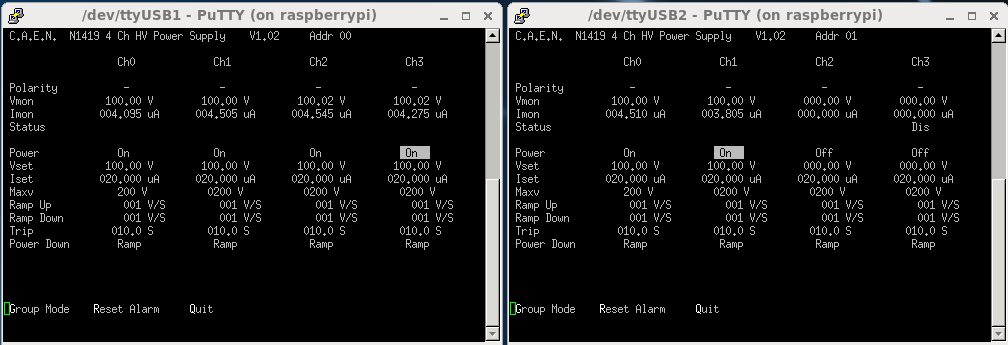
      Temps, bias and leakage currents (see attachment 14) all ok.

17.18 BigRIPS run 0183.
      ~1/2 way through R16_609.
      BRIKEN run 39.

18.27 BigRIPS file 0184 started. Start of R16_627.

18.31 Beam stopped at F11 for stripped foil change. Very end of R16_628.

18.38 Beam returned to F11. 1.3GB through R16_630.
      BigRIPS file 0185.
      BRIKEN run 40.

19.15 System-wide checks as previously.

19.38 BigRIPS file 0186. End of R16_654

19.43 BRIKEN file 41 started.

20.48 BigRIPS file 0187 started for 30Ne tuning.
      BRIKEN will not be taking data.

20:50 AIDA stopped on file R16_663
      Stopped as end of 39Na and the start of the BigRIPS sweep of settings.

20:52 BigRips starting with 30Ne

20:53 Started AIDA file R17. Centring beam along ZDS.
      F11 rate ~50cps. All variable degrader in (19mm).

20.58 BigRIPS file 0188 started.

21.04 30Ne setting started. BigRIPS file 0189 started.

21.20 30Ne stopped for 31Ne centring. BigRIPS file 0190.

21.27 BigRIPS file 0191 started for 31Ne yield measurement.
      (JLT has spoken with operators and it seems up until now beam has been stopped at F7. We are taking this to be the
case unless advised otherwise.)

21.59 BigRIPS file 0192 started on 32Ne yield setting. Beam to F11.

22.01 R17 stopped and R18 started.

22.05 32Ne setting finished.
      R18 stopped.

22.19 BigRIPS file 0194 started for 34Ne setting.
      AIDA run R19 started.
      BRIKEN run 43.
      Currently 10mm degrader but LISE predicts everything should pass through.

22.43 Degrader changed to 19mm Al at start of R19_6.
      LISE predicts implants in DSSD#2.

23.23 Beam stopped to F11. 1.8 GB into R19_15.

23.25 Beam returned to F11. 1GB into R19_16.
      BigRIPS file 0195.
Degrader reduced to 16.8mm Al. |
| Attachment 1: temps_31_a.png
|
|
| Attachment 2: bias_31_a.png
|
|
| Attachment 3: pulses_31_b.png
|
|
| Attachment 4: bias_31_b.png
|
|
| Attachment 5: spec_31_c.png
|
|
| Attachment 6: spec_31_d.png
|
|
| Attachment 7: bias_31_e.png
|
|
| Attachment 8: temp_31_e.png
|
|
| Attachment 9: 310317_bias1.png
|
|
| Attachment 10: 310317_temp1.png
|
|
| Attachment 11: 310317_bias2.png
|
|
| Attachment 12: 310317_temp2.png
|
|
| Attachment 13: 310317_bias3.png
|
|
| Attachment 14: bias_310317_1655.png
|
|
|
22
|
Thu Jan 22 13:50:33 2015 |
Alfredo and Tom | Further measurements with filtered PSU |
Jan 20, 2015

Test settings: DSSD biased at 100V, with 3.5 uA leakage current. Pulser at 0.5 V, split and inverted for both
positive and negative polarity. Frequency at 100 Hz.


++SHAPING TIME++

We varied shaping time (Tsh), and adjusted hold time (Th) accordingly. We measured the width of pulser spectra
for two channels using 'integrate' function of spectrum browser.

 Tsh	 Th	nnaida#11-2.6L	nnaida#13-2.6L
[usec]	[usec]	 FWHM [ch]	 FWHM [ch]
0.5	2	146		109
1	2	133		113
2	2	131		116
4	6	130		126
8	8	145		136

note: Tsh= ( 0.5*offset9 + 0.5) usec, Th= 2*offset7 usec

The first two data points where saved to file R44_0.gz, and R45_0.gz. Starting from the Tsh=2usec measurement,
NNAIDA#12 was causing communication issues with the merger/tape server, so we don't have files for last few.

Due to limited storange in AIDA PC, data was stored to external drive provided by Vic
(/media/data/TapeData/Test100/), and backued up temporarly also in Edinburhg
(/Disk/ds-sopa-personal/aestrade/data/AIDA/).


++THRESHOLDS++

Next step was to adjust threshold of the slow comparator, in order to lower them and take data looking for
background alpha radioactivity.

At this point NNAIDA#13 had stopped producing data (probably similar issue as NNAIDA#12, which could be
recovered with power cycling FEEs), so we used nnaida#14

FEE		Eth	rate/channel	integral(pulse peak):integral(noise peak)
nnaida#11	0x40	115 Hz (~only pulser)
nnaida#14	0x40	115 Hz(~only pulser)

nnaida#14	0x20	~350 Hz			2:1

nnaida#11	0x10	~150 Hz			1:2	(one channel very noisy @ 15kHz)
nnaida#14	0x10	~5 kHz (asic 1-3)	80:1
		0x10	~3kHz-100 Hz (asic 4)


For background run (see next elog entry) threshold values set at:
 nnaida#11= 0x16
 nnaida#12= 0x40
 nnaida#13= 0x20
nnaida#14= 0x16 |
|
840
|
Thu Jun 13 05:49:37 2019 |
CA | Further tests of calibration on Alpha data |
Alpha data used: /May19/{R1,R2,R7,R8,R9,R11} (c. 380 hr.)

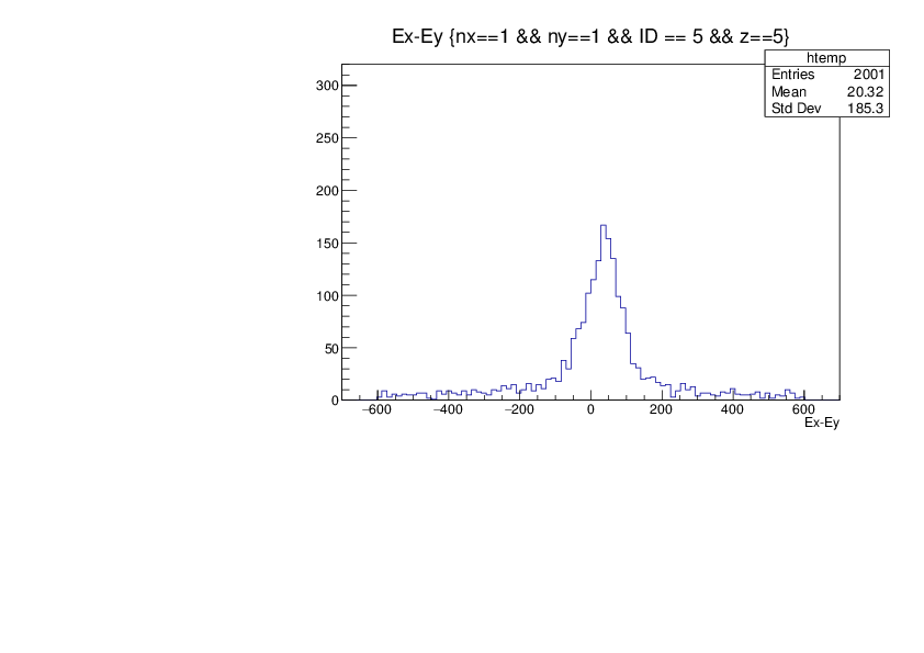
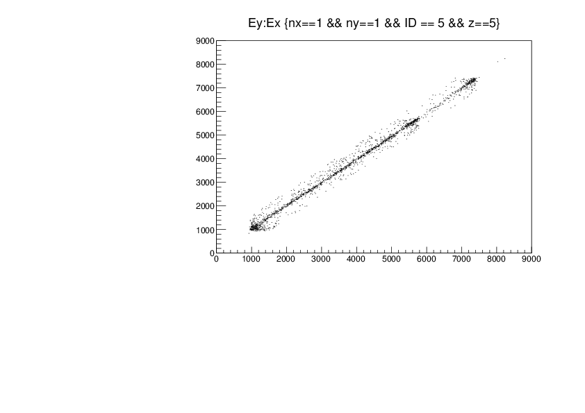
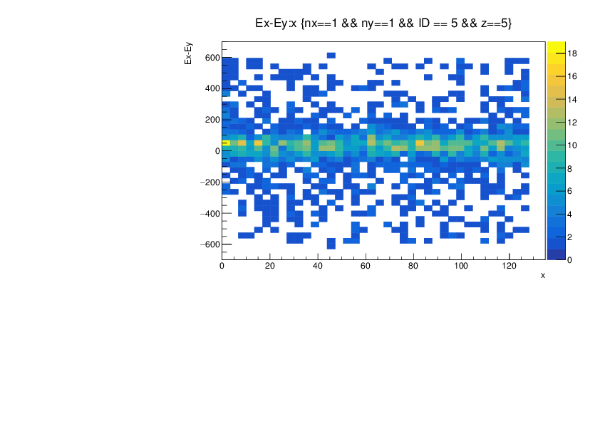
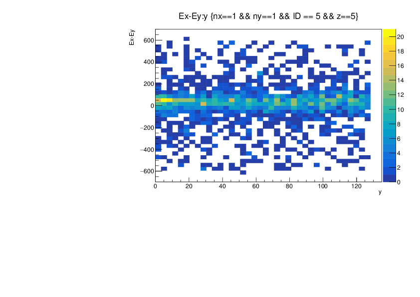
Absolute calibration calculated with relative calibrated data

Data then resorted with absolute and relative gains applied

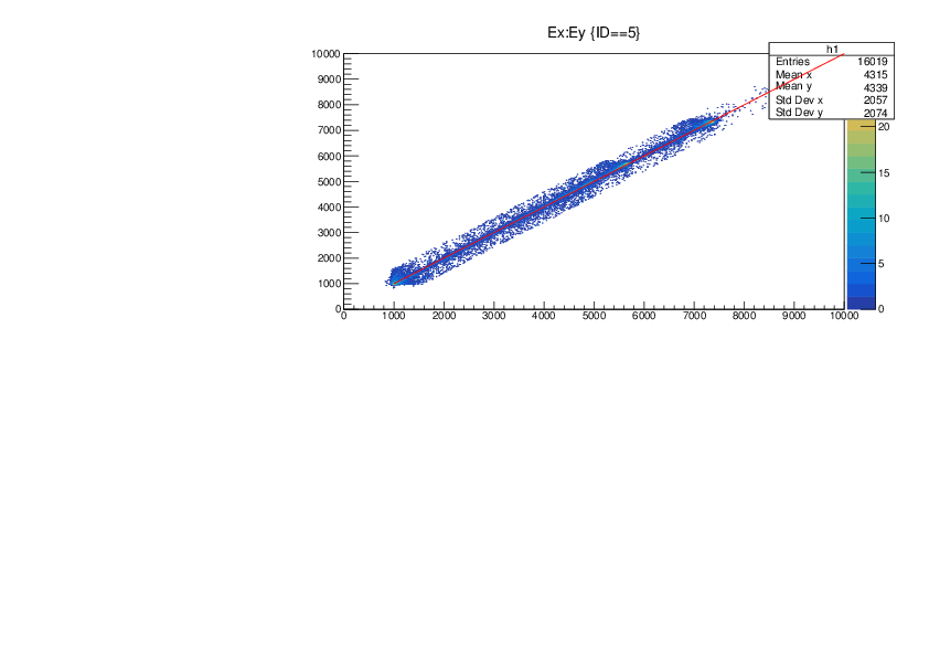
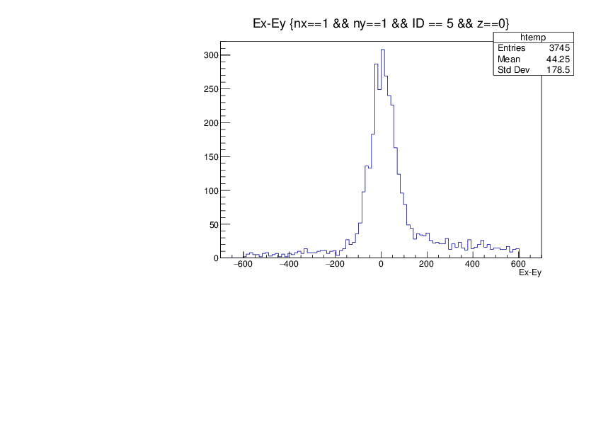
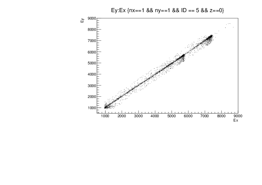
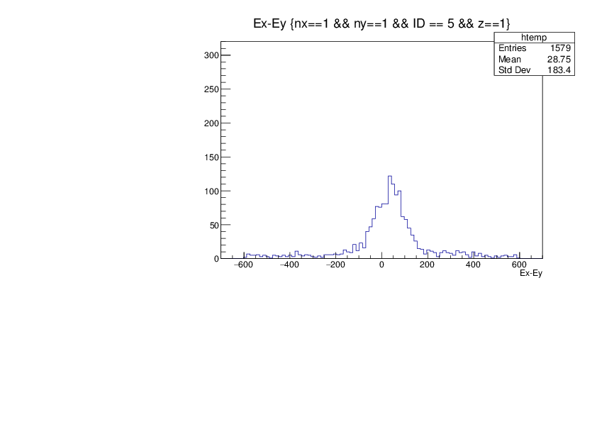
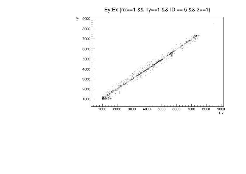
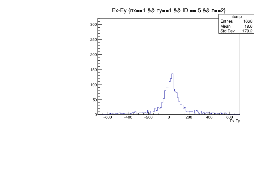
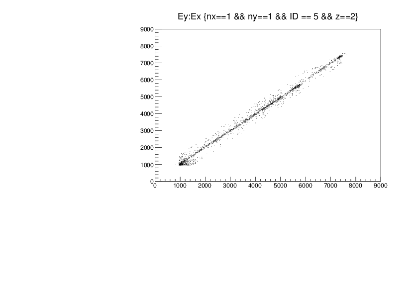
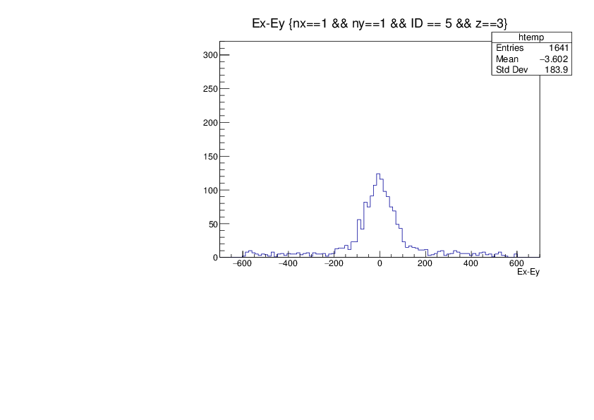
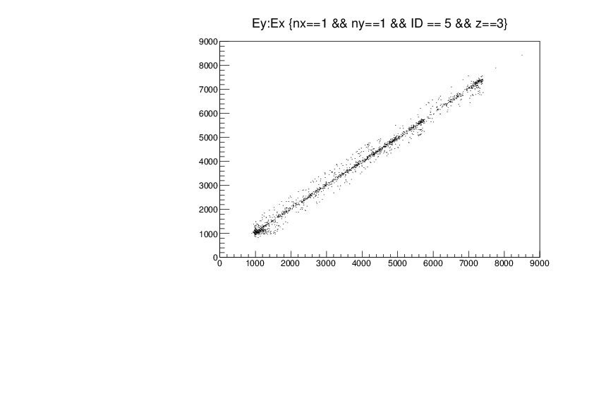
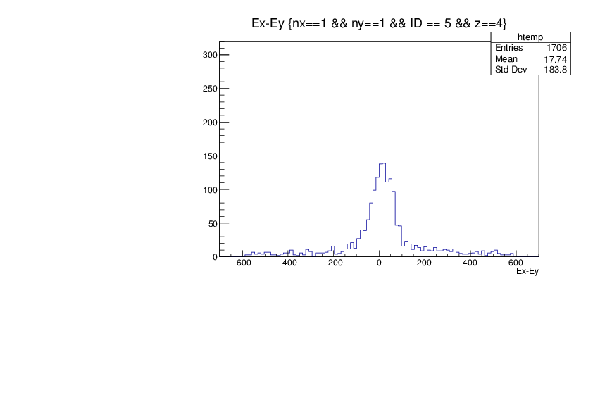
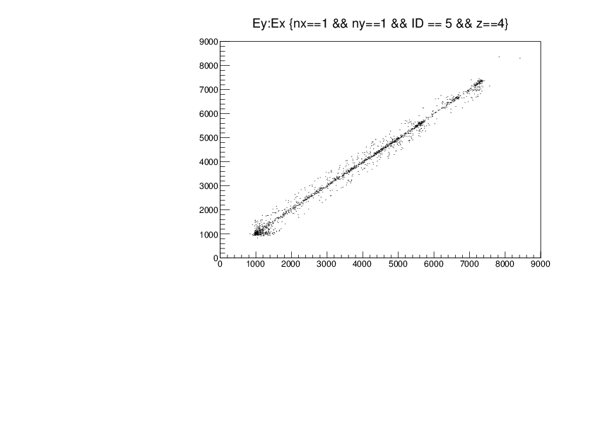
Attachment 1 -> Ey vs Ex plot for all detectors, with slope Ey=Ex show in red. Some non-linearity present, but to first order looks good

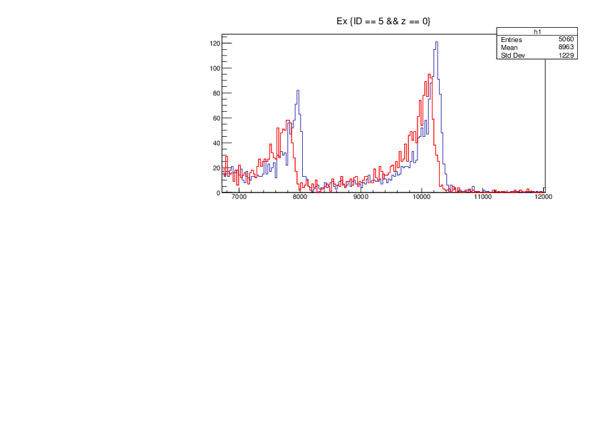
Attachment 2 -> Alpha peaks pre- absolute calibration in DSSD0
                Ex in blue, Ey in red
                To determine absolute calibration coefficients, assigned leading edge of higher energy peak an energy of 7.4 MeV (Uranium decay series)
                Divide this by the observed channel number (in keV) to get the absolute gain coefficients in keV/ch for Ex and Ey in each detector.
                (Note, data already offset corrected, pulser walkthrough)
                Values typically ~0.72 keV/ch
                Multiply appropriately by relative gains obtained from gainMatch.cpp to get final gain coefficients.

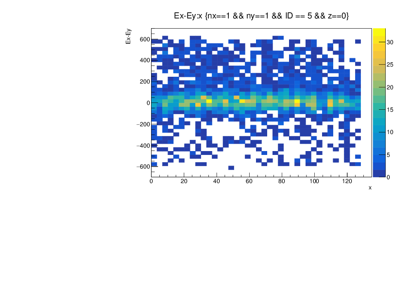
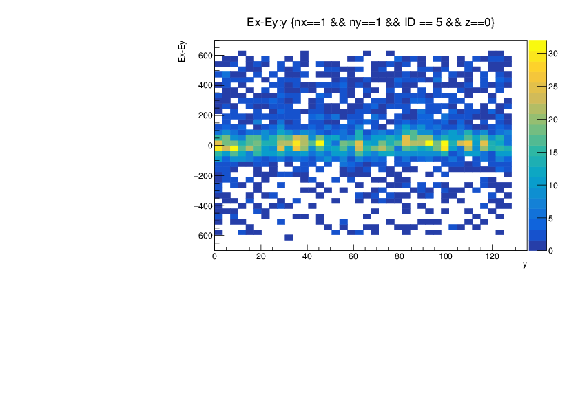
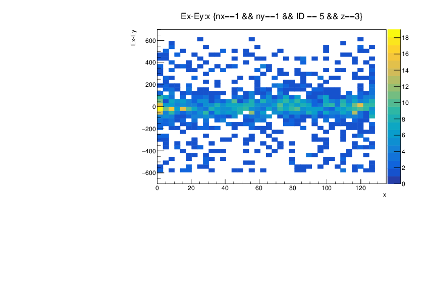
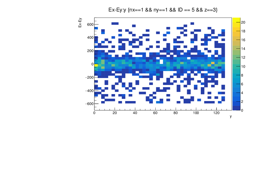
Attachments 3 - 6 -> DSSD0 -> Ex - Ey
                           -> Ey vs Ex
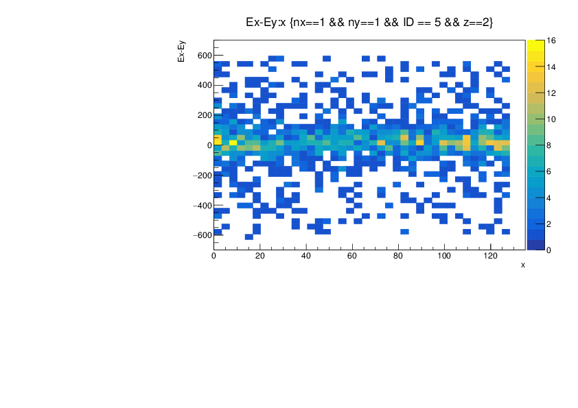
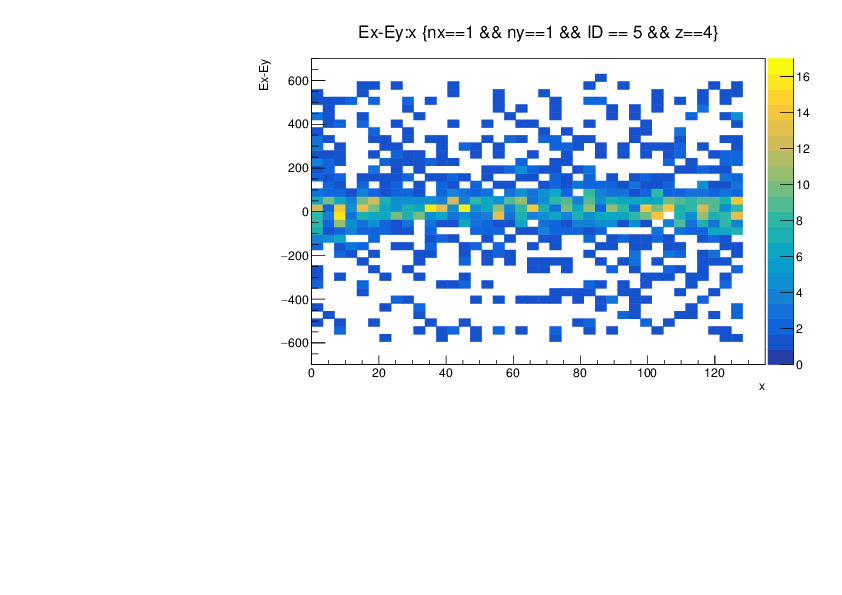
                           -> Ex - Ey vs x strip
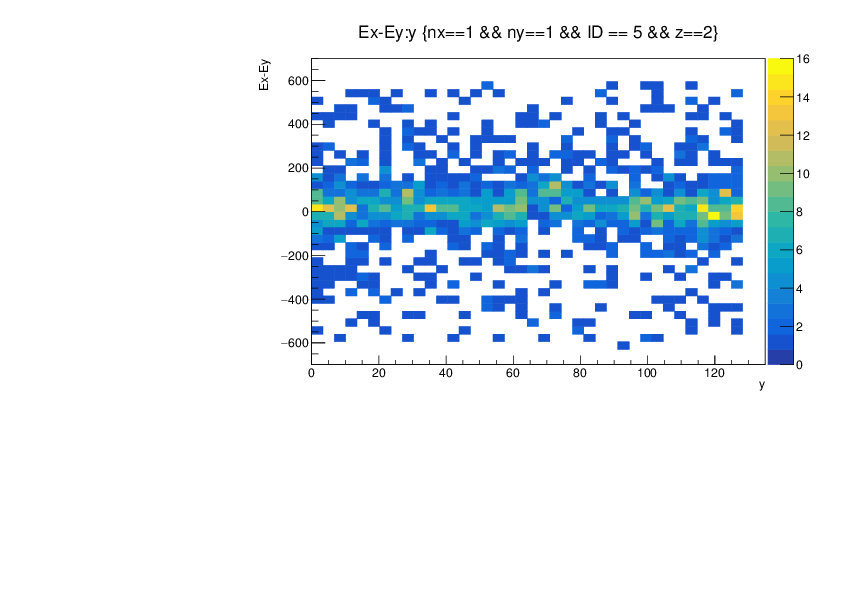
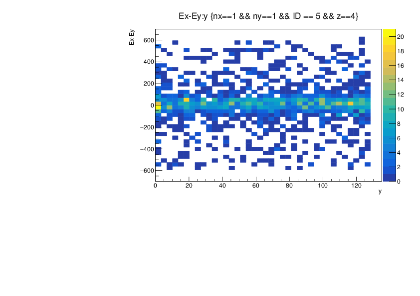
                           -> Ex - Ey vs y strip

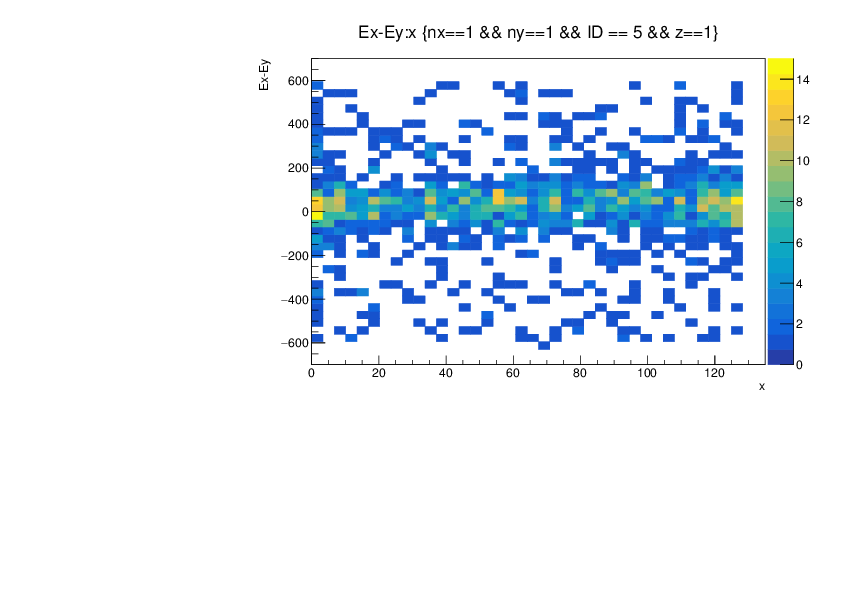
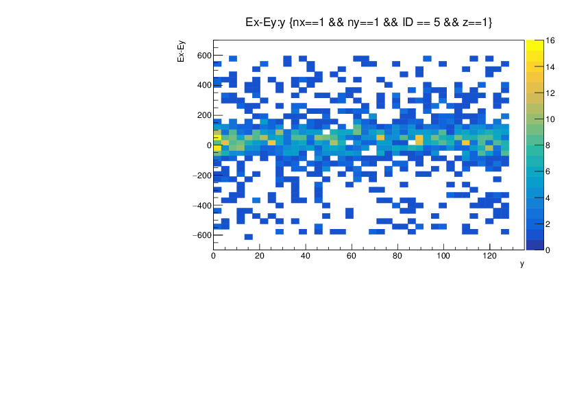
Attachments 7 - 10 -> DSSD1 -> Ex - Ey
                            -> Ey vs Ex
                            -> Ex - Ey vs x strip
                            -> Ex - Ey vs y strip

Attachments 11 - 14 -> DSSD2 -> Ex - Ey
                             -> Ey vs Ex
                             -> Ex - Ey vs x strip
                             -> Ex - Ey vs y strip

Attachments 15 - 18 -> DSSD3 -> Ex - Ey
                             -> Ey vs Ex
                             -> Ex - Ey vs x strip
                             -> Ex - Ey vs y strip

Attachments 19 - 22 -> DSSD4 -> Ex - Ey
                             -> Ey vs Ex
                             -> Ex - Ey vs x strip
                             -> Ex - Ey vs y strip

Attachments 23 - 26 -> DSSD5 -> Ex - Ey
                             -> Ey vs Ex
                             -> Ex - Ey vs x strip
                             -> Ex - Ey vs y strip

Attachment 27 -> Table comparing sigma and peak centroids of Ex - Ey plots for each DSSD
                 Calculated using simple gaussian fit
|
| Attachment 1: CalibSlope.pdf
|
|
| Attachment 2: z0ExplusEy.pdf
|
|
| Attachment 3: z0Ediff.pdf
|
|
| Attachment 4: z0exey.pdf
|
|
| Attachment 5: z0xdiff.pdf
|
|
| Attachment 6: z0ydiff.pdf
|
|
| Attachment 7: z1Ediff.pdf
|
|
| Attachment 8: z1exey.pdf
|
|
| Attachment 9: z1xdiff.pdf
|
|
| Attachment 10: z1ydiff.pdf
|
|
| Attachment 11: z2Ediff.pdf
|
|
| Attachment 12: z2eyex.pdf
|
|
| Attachment 13: z2xdiff.pdf
|
|
| Attachment 14: z2ydiff.pdf
|
|
| Attachment 15: z3Ediff.pdf
|
|
| Attachment 16: z3exey.pdf
|
|
| Attachment 17: z3xdiff.pdf
|
|
| Attachment 18: z3ydiff.pdf
|
|
| Attachment 19: z4Ediff.pdf
|
|
| Attachment 20: z4eyex.pdf
|
|
| Attachment 21: z4xdiff.pdf
|
|
| Attachment 22: z4ydiff.pdf
|
|
| Attachment 23: z5Ediff.pdf
|
|
| Attachment 24: z5eyex.pdf
|
|
| Attachment 25: z5xdiff.pdf
|
|
| Attachment 26: z5ydiff.pdf
|
|
| Attachment 27: Screenshot_from_2019-06-13_06-18-42.png
|

|
|
288
|
Tue Jun 7 05:48:13 2016 |
TD, AE, ML & PJW | HEC spectra & implant profile |
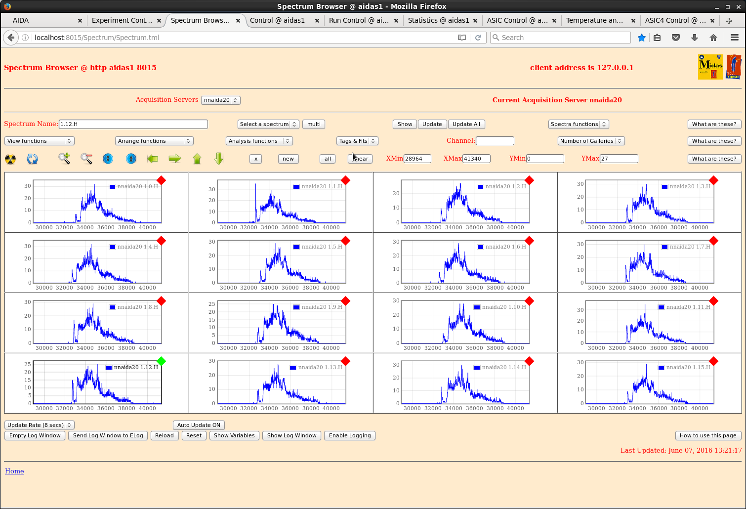
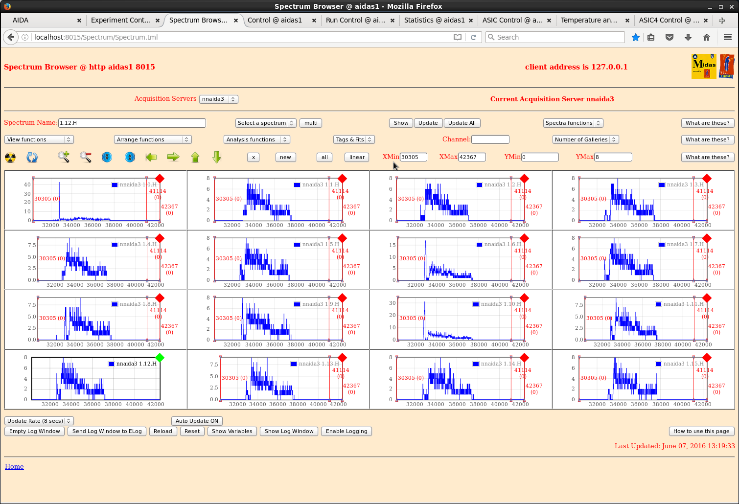
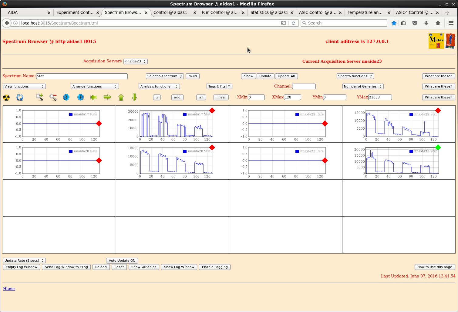
DSSSD#1 and DSSSD#6 ADC hit patterns (profile) and 1*H (ASIC#1 20GeV FSR) energy spectra |
| Attachment 1: 30.png
|
|
| Attachment 2: 36.png
|
|
| Attachment 3: 40.png
|
|
|
790
|
Fri Nov 16 06:01:47 2018 |
CA | High Energy Channel Ex vs Ey for different degrader thicknesses |
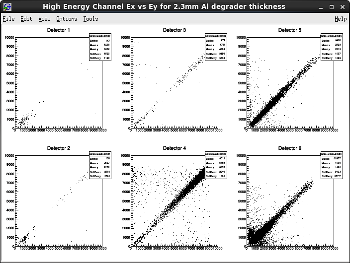
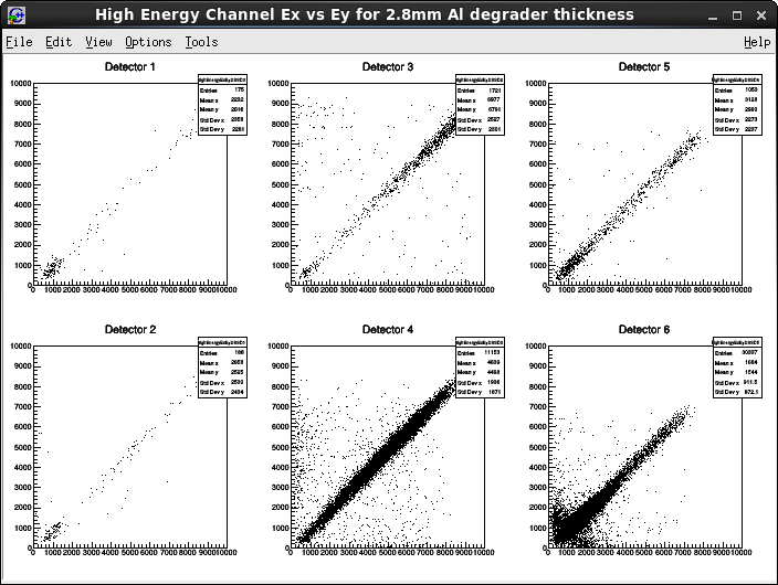
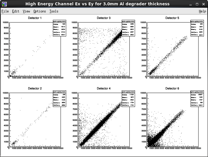
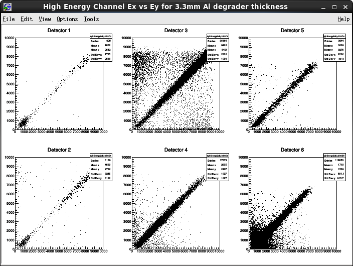
15.04 Plots of X Energy vs Y Energy for each detector, and for 4 different Al degrader thicknesses, as indicated
on each graph. (Attachments 1-4) |
| Attachment 1: 2_3HECexey.png
|
|
| Attachment 2: 2_8HECexey.png
|
|
| Attachment 3: 3_0HECexey.png
|
|
| Attachment 4: 3_3HECexey.png
|
|
|
86
|
Thu Apr 30 15:28:25 2015 |
Patrick Coleman-Smith | High Energy Spectra from LYCCA with pulser |
I have an eight FEE64 system now in place on the LYCCA chamber with a PB-5 pulser going into the adapter cards test input. The test capacitor is 30pF.
I was going to explore the effect of the thresholds on the pulser peak.
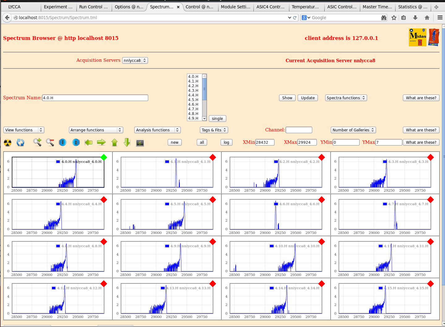
I notice that the spectra look like those taken in RIKEN and not a single peak. In the 1GeV range I would interpret this as noise but since this is such a high energy i don't quite understand what is happening in the ASIC.
I thought i would share it with you.
PB-5 input to 50R is 10v with no attenuation. Signal height on the inline 'scope is +5.2v
ASICs are set to "default" with 1GeV range and 3uS shaping time.
Let me know if anything useful can be gleaned by more tests on LYCCA. |
| Attachment 1: LYCCA_High_Energy.png
|
|
|
88
|
Thu Apr 30 17:43:36 2015 |
Patrick Coleman-Smith | High Energy Spectra from LYCCA with pulser |
I have an eight FEE64 system now in place on the LYCCA chamber with a PB-5 pulser going into the adapter cards
test input. The test capacitor is 30pF.

I was going to explore the effect of the thresholds on the pulser peak.

I notice that the spectra look like those taken in RIKEN and not a single peak. In the 1GeV range I would
interpret this as noise but since this is such a high energy i don't quite understand what is happening in the
ASIC.

I thought i would share it with you.

PB-5 input to 50R is 10v with no attenuation. Signal height on the inline 'scope is +5.2v

ASICs are set to "default" with 1GeV range and 3uS shaping time.

Let me know if anything useful can be gleaned by more tests on LYCCA.


Q = CV = 30pF * 5V = 150pC => ~ 3.42GeV => ADC channel ~ 27880

The spectra imply a positive test input. The spectra imply an inconsistency between the data
supplied and the peak position.

You display the spectra on a log scale ...  so the majority of events are in the peak ... but
why do some channels so a peak and others a peak plus a small number of higher amplitude/events?

What ASIC settings are you using?

What is the PB-5 frequency? ... PB-5 settings? |
|
89
|
Thu Apr 30 20:21:20 2015 |
Patrick Coleman-Smith | High Energy Spectra from LYCCA with pulser |
> I have an eight FEE64 system now in place on the LYCCA chamber with a PB-5 pulser going into the adapter cards
> test input. The test capacitor is 30pF.
>
> I was going to explore the effect of the thresholds on the pulser peak.
>
> I notice that the spectra look like those taken in RIKEN and not a single peak. In the 1GeV range I would
> interpret this as noise but since this is such a high energy i don't quite understand what is happening in the
> ASIC.
>
> I thought i would share it with you.
>
> PB-5 input to 50R is 10v with no attenuation. Signal height on the inline 'scope is +5.2v
>
> ASICs are set to "default" with 1GeV range and 3uS shaping time.
>
> Let me know if anything useful can be gleaned by more tests on LYCCA.
>
>
>
> Q = CV = 30pF * 5V = 150pC => ~ 3.42GeV => ADC channel ~ 27880
>
> The spectra imply a positive test input. The spectra imply an inconsistency between the data
> supplied and the peak position.
>
> You display the spectra on a log scale ...  so the majority of events are in the peak ... but
> why do some channels so a peak and others a peak plus a small number of higher amplitude/events?
>
> What ASIC settings are you using?
>
> What is the PB-5 frequency? ... PB-5 settings?

PB-5 is at 100Hz, fall time is 1 ms.
ASIC settings default from VHDL.
They are in the manual. See EDOC955 at npg.dl.ac.uk

29300 => 2.1GeV ( very approx )  so yes this doesn't make sense.
Hard to have a specific calibration or will your beam time give that.

I think the 30pF is correct but i can measure it on Wednesday...... |
|
30
|
Tue Feb 10 16:01:50 2015 |
Chris Griffin, Alfredo Estrade | High data rate - Pause/Resume |
06/02/15
A look at the data rate at which Pause/Resumes start to cause missing data.
Pulser settings:
Slow comparitor thresholds were altered using the ASIC4 page to artificially increase the data rate in the ASICs.
Default settings for all modules, apart from the changing slow comp threshold.
nnaida13+14 both functioning well. nnaida11+12 both have one noisy channel contributing to high data rate.
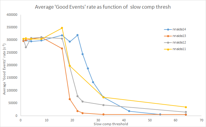
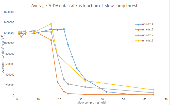
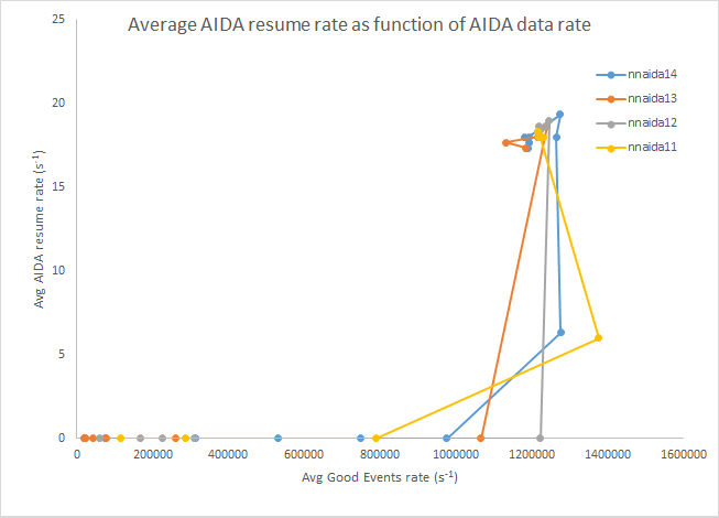
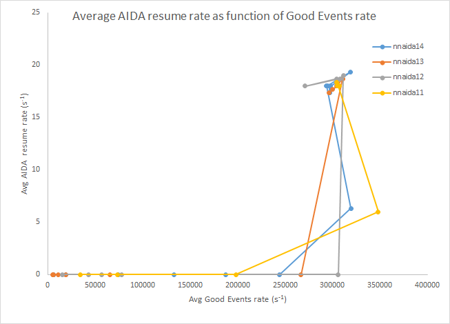
Echoing Alfredo's previous post, using the AIDA Good Events and AIDA Data Rate from the stats page as metrics, I found there to be no Pause/Resume items present in the data up to a Good Events rate of ~250-300 kHz and Data Rate of ~1-1.2 MHz.
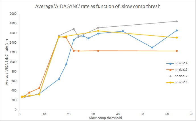
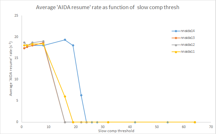
Around this point the data shifts very quickly from containing no Pause/Resume items to having a rate of ~18 Hz, almost as a step function. At this point the Good Events and AIDA data rate sharply reach a maximum rate of 300 kHz and 1.2 MHz respectively. The rate of AIDA SYNC data items drops sharply at this point and decreases slowly with decreasing threshold.
Included are some plots showing this for each of the modules and some summary plots.
Further to the data rate at which the appearance of Pause/Resume items causes significant data loss, I looked at what happens when you break this threshold and then come back down, i.e. do the Pause/Resume items persist?
In short, no. Starting from a threshold of 64 and working down to 1, then taking the slow comparitor threshold back to a level at which no Pause/Resumes were present, the Good Events, AIDA SYNC and AIDA Data rates all went back to their original values within a couple of refreshes of the stats screen (and stayed as such thereafter). |
| Attachment 1: GoodEvts_v_thresh.png
|
|
| Attachment 2: AIDAdata_v_thresh.png
|
|
| Attachment 3: AIDAsync_v_thresh.png
|
|
| Attachment 4: PauseResume_v_thresh.png
|
|
| Attachment 5: ResumeRate_v_AIDAdata.png
|
|
| Attachment 6: ResumeRate_v_GoodEvts.png
|
|
|
894
|
Sat Sep 30 16:37:06 2023 |
TD | Honeywell HSS-DPS fault |
The Honeywell HSS-DPS dew point sensor indicator ( red LED ) is flashing c. 0.5Hz indicating humiidity > 90+/-3 %

Hanna HI9565 report d.p. 8.3 deg C, RH 36%, temperature 25 deg C

S4 area coolant water cntrols indicate water temperature 19 deg C. No evidence of condensation on AIDA coolant manifold.

Sensor fault? |
|
42
|
Fri Feb 20 10:48:09 2015 |
TD | How To Connect the FEE64 System Console Using PuTTY |
Set permissions for the USB-serial device using the command

sudo chmod 777 /dev/ttyUSB0

Note: Vic Pucknell reports that he has sometime observed the device
rotate between /dev/ttyUSB0, /dev/ttyUSB1, /dev/ttyUSB2 etc - make\
sure you are using the correct device name with the command:

ls -l /dev/ttyUSB*


Start PuTTY

Select Connection Type 'Serial'
Enter Serial Line (/dev/ttyUSB0 or /dev/ttyUSB1)
Enter speed (9600)
Select 'Open'

Note: permissions for the USB-serial device will revert to their
default (mode 440) when the OS notices the change but by then
the serial line connection will have been established. |
|
98
|
Mon May 4 02:32:29 2015 |
VFEP & TD | How to fix DAQ stalls at GO |
It has been observed that when starting the AIDA data acquisition (select 'GO' from the 'Data Acquisition Run
Control' window) that from time to time one, or possibly more, FEE64 modules fail to begin producing data.
Once running they appear to be totally reliable.

The result is that these FEE64 modules produce no AIDA SYNC data items or ASIC Events - they may still
produce WAVE SYNC and Wave Events.

The best check to make after starting the AIDA data acquisition is to select 'Data Acquisition Statistics'
from the 'Data Acquisition Run Control' window. In the 'Data Acquisition Statistics' window check that
'Show ALL Data Acquisition Servers?' is selected. From the 'Select counter to monitor' menu select
'AIDA SYNC' and select 'Update Once' to update the counters and rates.

Check that all FEE64 modules show a rate of ~1500/s.

If you see 0 then that module has failed to start.

The recommended procedure is:

 1) Make a note of the FEE64 module which is not producing AIDA SYNCs.

 2) Go to the 'Merge Control' window and select 'Reload'.

    The status banner should show
        'Merge State = GOing     :    merging     :     xfer enabled   :    waiting for SYNC'

    Select 'Toggle Merge Program Pause State'. The status banner should show
        'Merge State = GOing     :    paused     :     xfer enabled   :    waiting for SYNC'

    In this state the Merge software will read data from all links but discard the data and make no attempt
    to time align the data streams which is impossible if one, or more, streams is not producing AIDA SYNC
    data items.

 3) Return to the 'Data Acquisition Run Control' window
    Deselect 'Act on ALL Data Acquisition Servers?'
    Select the FEE64 module which is not producing AIDA SYNC data items from the 'Acquisition Servers' menu.
    From the 'System functions (Only use if you know what they do!!!)' menu select 'Go Electronics'.

    This will reset and restart the electronics for this FEE64 module without changing any setting.

    If you now check the 'Run Control Data Acquisition Statistics' window, hopefully you will see
    that the FEE64 module is now producing AIDA SYNC data items.

 4) If so, return to the Merge Control window.
    Select 'Toggle Merge Program Pause State' and the status should change from 'paused' to 'merging'.
    After a few second you will hopefully observe the Merge software begin to time align the data streams
and start producing a merged, time-ordered data stream. |
|
307
|
Sat Jun 11 13:57:09 2016 |
laura | How to monitor and check synchronisation of FEES |
Alfredo has written a program to check the synchronisation of the FEES, which need to be checked regularly
To do this:
change to directory: npg/AIDAanalysis/AIDAmonitor
Command: nice ./AIDA-sort.exe -F filename e.g. nice ./AIDA-sort.exe -F AIDA37_10
Be patient, it takes a while to sort the file. It is possible to monitor the output in the directory npg/AIDAanalysis/ORDERsort/aev by the command ls -trlh /data10/NP1512.rootfiles
However, there is no need to wait for the raw date in the full 2GB to be converted to .root. It is possible to pause it by pressing the space bar, then choosing the options (0 to stop)
Once stopped, command: nice root -l /data10/NP1512.rootfiles/aida_sort_AIDAfilename.root e.g. nice root -l /data10/NP1512.rootfiles/aida_sort_AIDA37_10.root
Root will then open.
Command: .x checkSYNC.c
--------------------------------
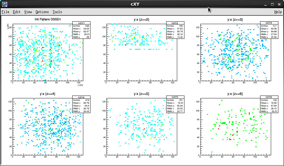
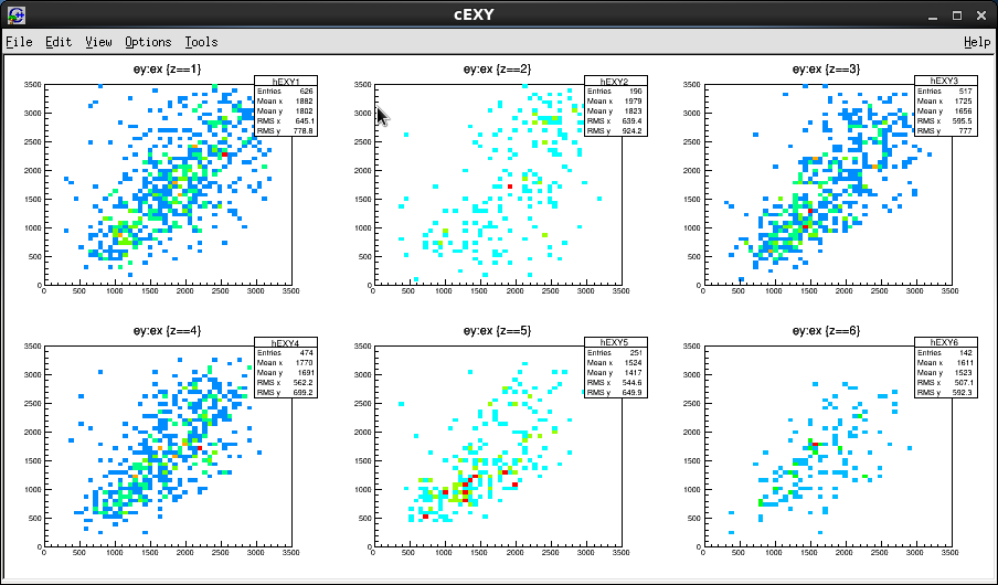
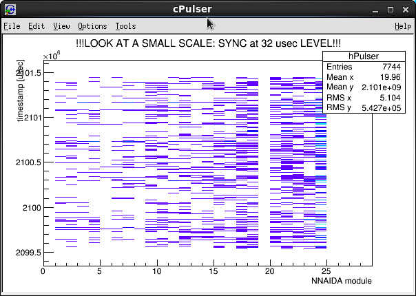
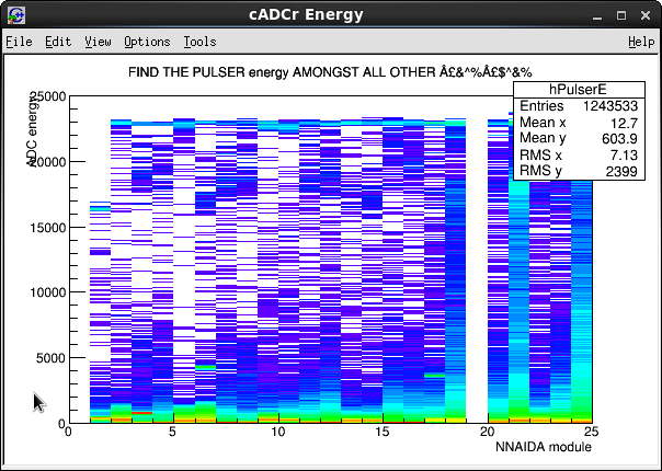
Four canvases will open: (1) cxy for each DSSD, (2) cExy for each DSSD, (c) cpulser: timestamp vs NNAIDA module and (d) CADC Energy: ADC energy vs NNAIDA module
* Check in cxy that all 4 quadrants have data (excluding those corresponding to nnaida19, which is currently inactive). If there is asymmetry (eg missing quadrants) there is probably a synchronisation problem!!
*Check in cEXY that there is a y=x correlation. If it isn't, there is probably a synchronisation problem!!
If there is a synchronisation problem, it may be necessary to power cycle. Switch all off, then sequence all on, follow AIDA elog entry 242 https://elog.ph.ed.ac.uk/AIDA/242
|
| Attachment 1: eg1.png
|
|
| Attachment 2: eg2.png
|
|
| Attachment 3: eg3.png
|
|
| Attachment 4: eg4.png
|
|
|
31
|
Sun Feb 15 06:12:00 2015 |
TD, AEV & CG | How to mount USB disk with NTFS |
Mount external USB expansion disk with NTFS filesystems
with the (superuser) command:

su root
password:

mount -t ntfs-3g /dev/sdd1 /ntfs

[root@aidas1 /]# df -h
Filesystem            Size  Used Avail Use% Mounted on
/dev/mapper/vg_aidas1-lv_root
                       50G   33G   15G  69% /
tmpfs                 3.9G  4.3M  3.9G   1% /dev/shm
/dev/sda1             485M   61M  399M  14% /boot
/dev/mapper/vg_aidas1-lv_home
                      860G  201M  816G   1% /home
/dev/mapper/Data1-data10
                      1.8T  1.4T  309G  83% /data10
/dev/sdd1 3.7T 1.3T 2.4T 36% /ntfs |
|
20
|
Wed Dec 3 12:13:03 2014 |
Alfredo Estrade | IV curve with CAEN N1419 |
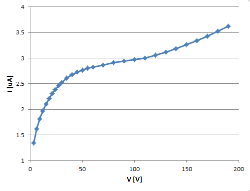
Measured IV curve for BB18 DSSD with new CAEN HV supply. Settings as in previous elog entry:

Detector bias CAEN N1419 Programmable HV Power Supply
  - FAGND isolated from AGND (AGND = NIM chassis ground)
  - floating HV supply, <5mV pp noise specification
  - configured + polarity, i.e. core to nnaida11 & nnaida12 MSL type BB18 n+n ohmic strips
                                braid to nnaida12 & nnaida13 MSL type BB18 p+n junction strips


Data (see attachment):
V [V]	I [uA]
3	1.34
6	1.62
9	1.81
12	1.97
15	2.1
18	2.21
21	2.31
24	2.39
27	2.46
30	2.52
35	2.61
40	2.68
45	2.73
50	2.77
55	2.8
60	2.82
70	2.86
80	2.91
90	2.94
100	2.97
110	3
120	3.06
130	3.12
140	3.18
150	3.26
160	3.34
170	3.43
180	3.53
190 3.62 |
| Attachment 1: IV_dec14.PNG
|
|
|
372
|
Thu Oct 6 12:39:14 2016 |
TD | Images of setup at F11 |
|
| Attachment 1: IMG_6687.JPG
|
|
| Attachment 2: IMG_6689.JPG
|
|
| Attachment 3: IMG_6690.JPG
|
|
|
373
|
Thu Oct 6 13:09:50 2016 |
TD | Images of setup at F11 - 2 |
|
| Attachment 1: IMG_6692.JPG
|
|
| Attachment 2: IMG_6693.JPG
|
|
| Attachment 3: IMG_6694.JPG
|
|
|
375
|
Thu Oct 6 13:20:34 2016 |
TD | Images of setup at F11 - 3 |
|
| Attachment 1: IMG_6695.JPG
|
|
| Attachment 2: IMG_6696.JPG
|
|
| Attachment 3: IMG_6701.JPG
|
|
|
377
|
Thu Oct 6 13:22:24 2016 |
TD | Images of setup at F11 - 4 |
|
| Attachment 1: IMG_6702.JPG
|
|
|
502
|
Wed Nov 30 06:31:04 2016 |
PV, TD, RCF, Liu | Implantation profile in AIDA R39 2 to 9, after changing degrader at 13:30 |
Degrader setting was:
Variable degrader:
0.5 mm W + 1 mm Al : in
0.3 mm W + 1 mm Al : out
1 mm W + 1 mm Al : in
Fix degrader:
20mm Al+ 0,2 mm Al

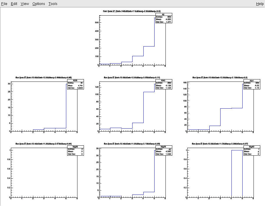
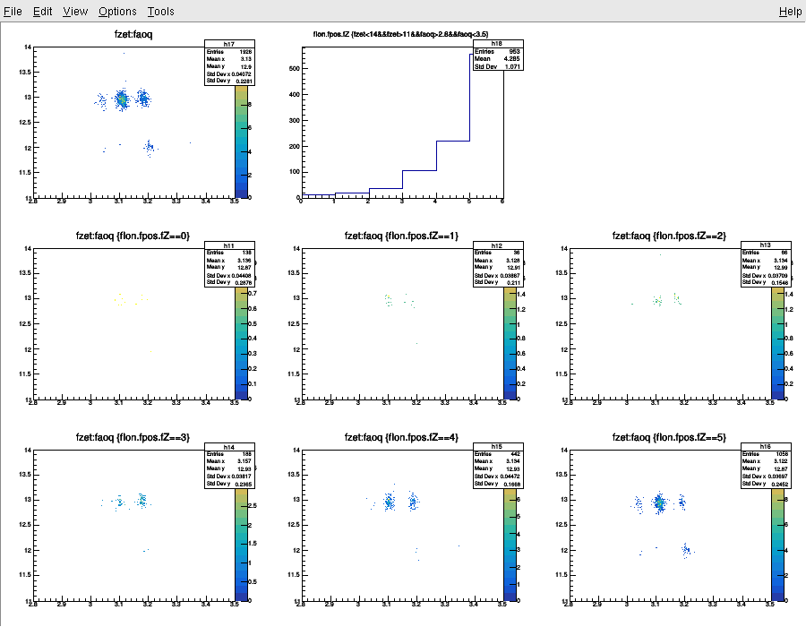
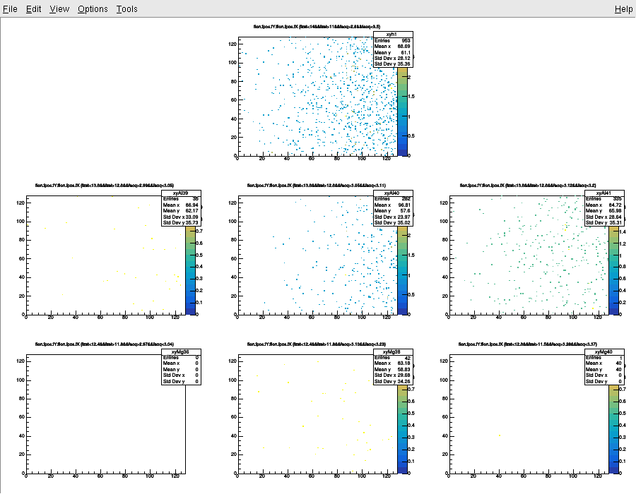
Large portion of the beam is passing through AIDA! We need to change the degrader |
| Attachment 1: 29.png
|
|
| Attachment 2: 22.png
|
|
| Attachment 3: 12.png
|
|