| |
ID |
Date |
Author |
Subject |
|
|
140
|
Fri Jan 15 16:50:09 2016 |
CG, TD | Ribbon cable + couple tests at DL |
12/01/16 (Attachments 1-8)
FEEs set up as per ELOG entry 136 (15/12/15)
Connected cables as follows:
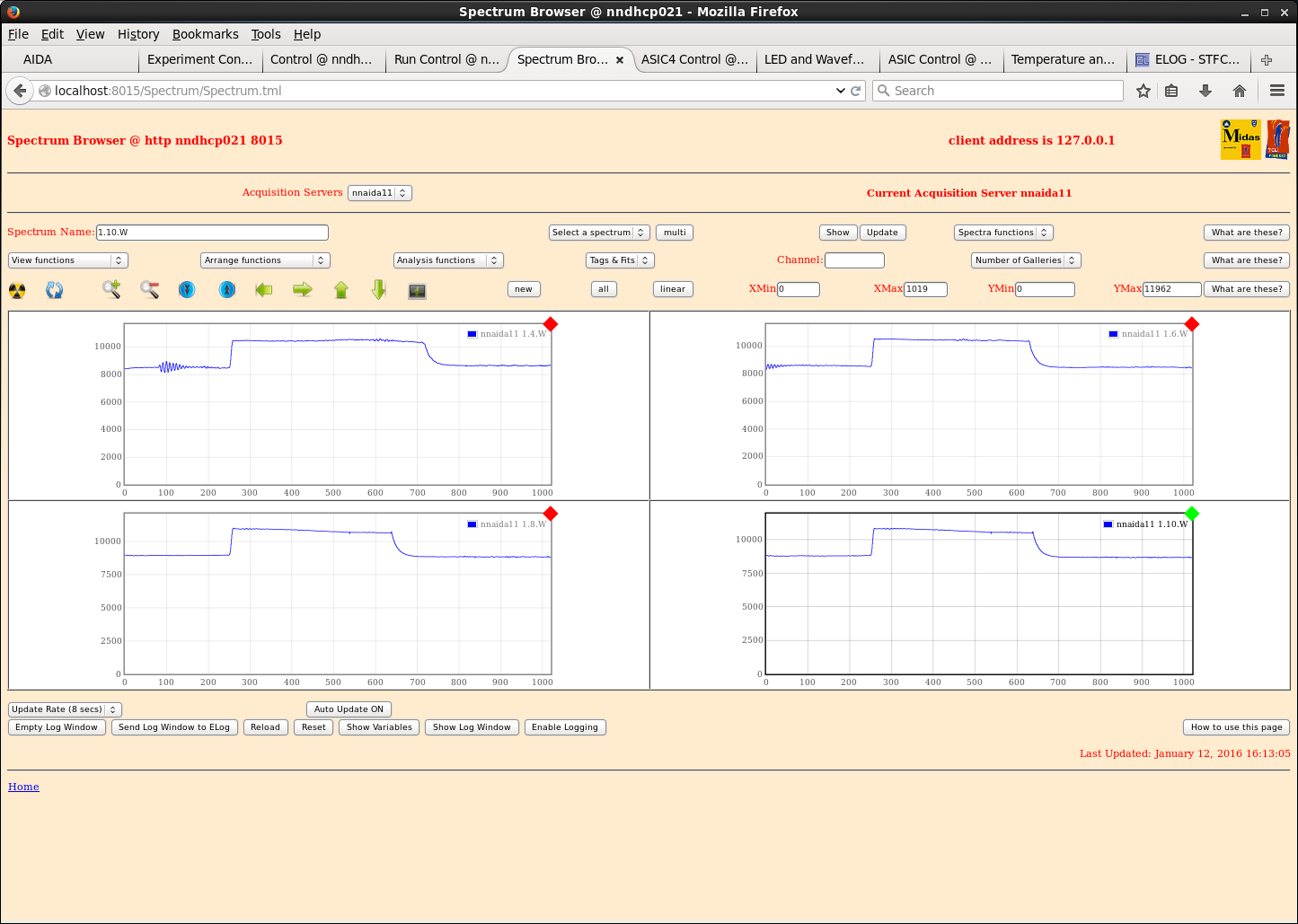
- nnaida11 > LH coupler + 45cm ribbon (unshielded)
- nnaida12 > no load (no waveforms from this card)
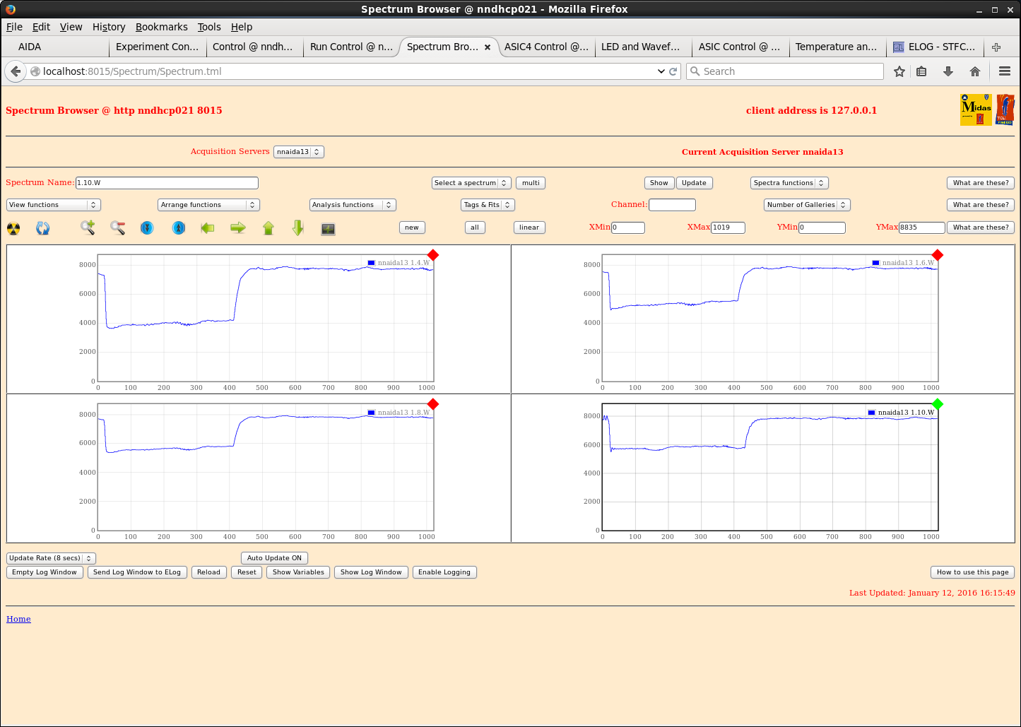
- nnaida13 > LH coupler + 45cm ribbon (unshielded) + RH coupler
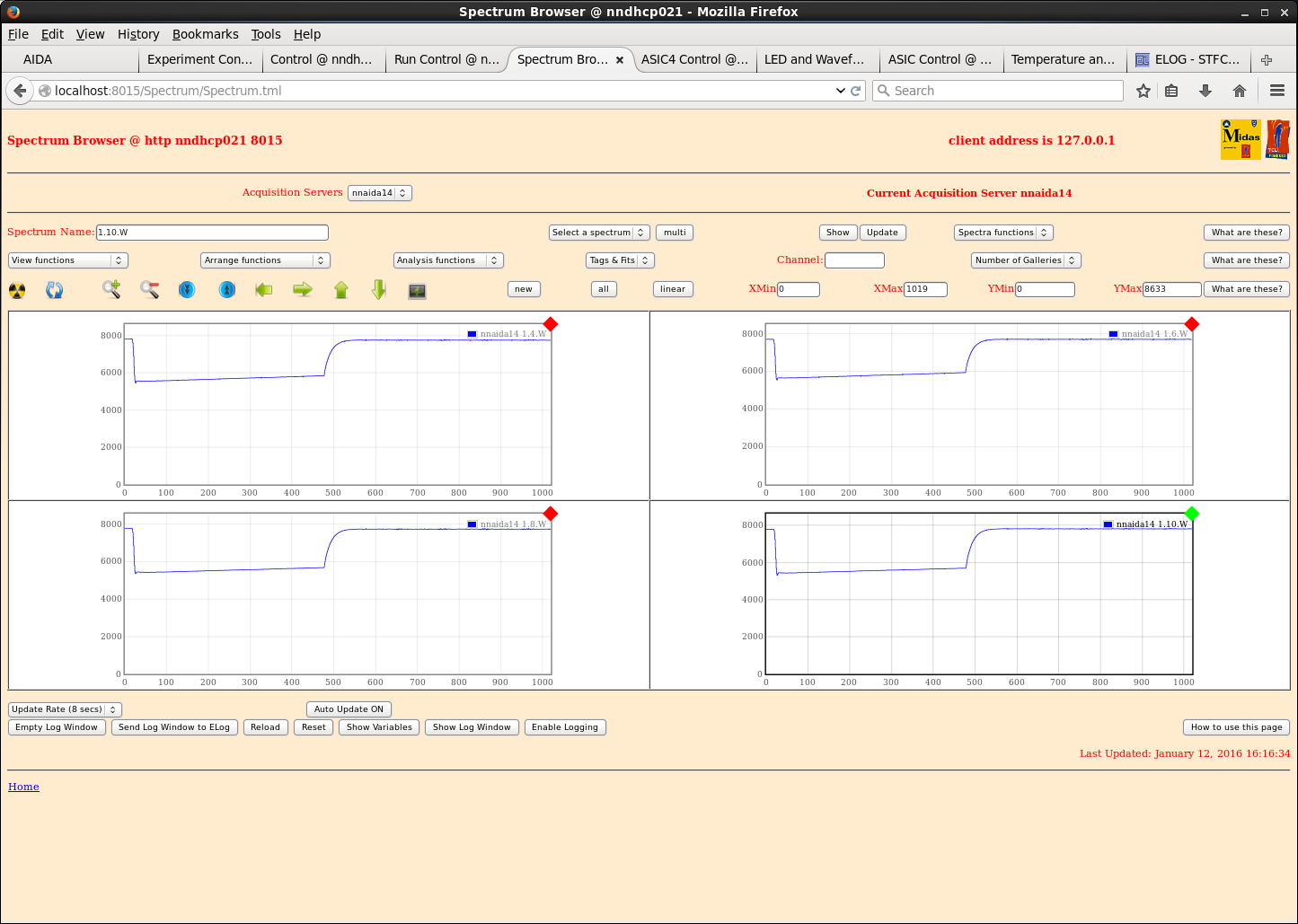
- nnaida14 > LH coupler
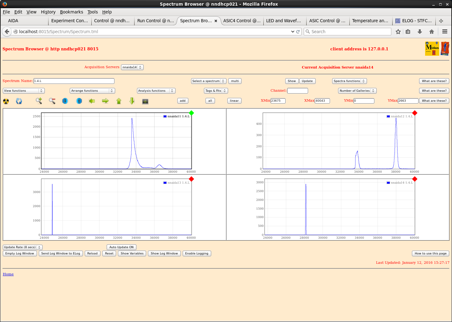
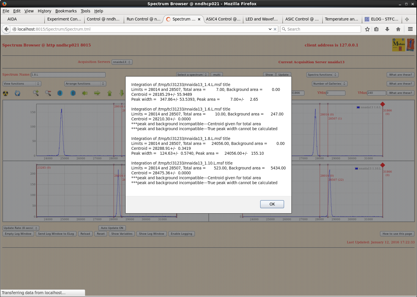
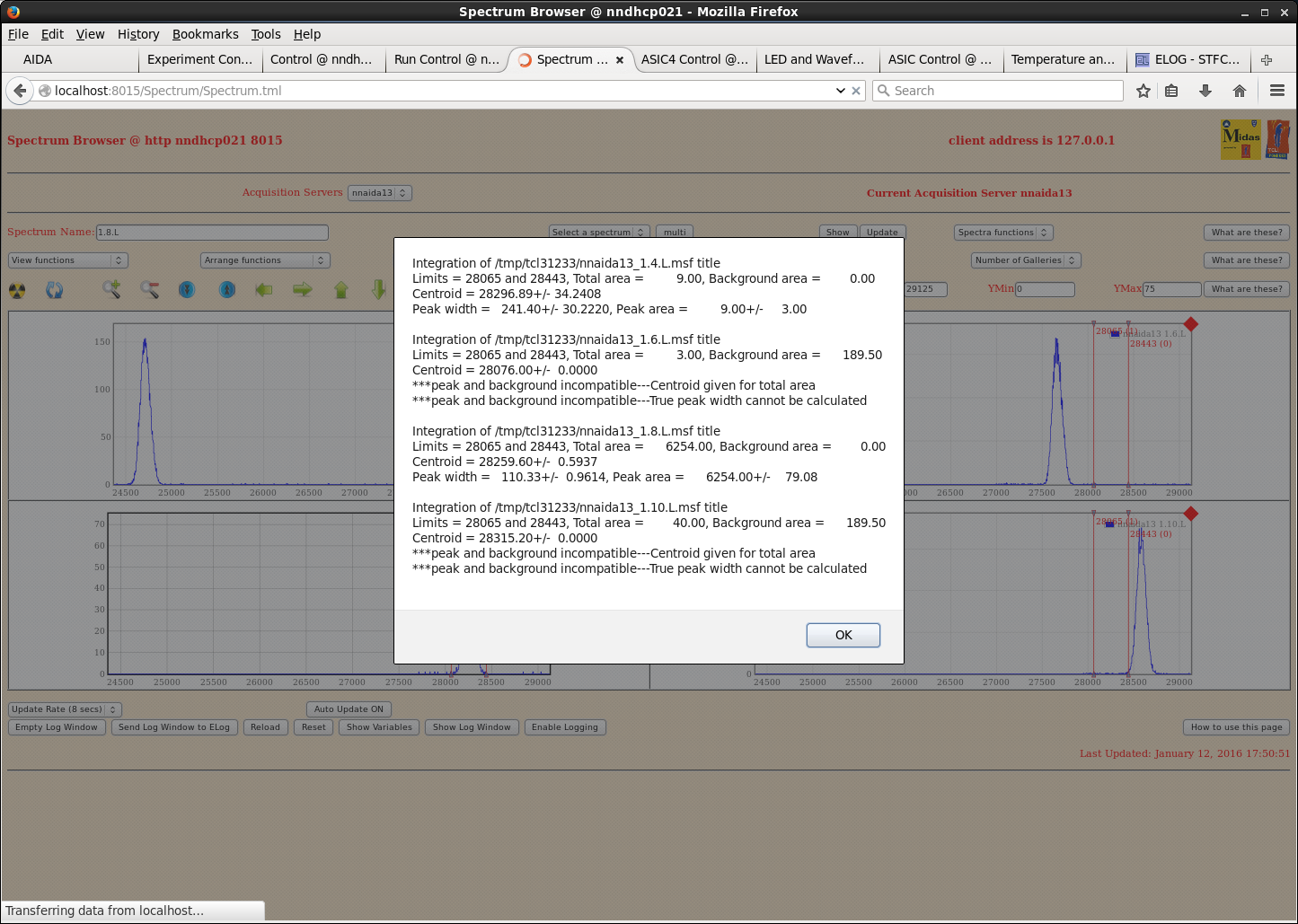
Peak widths (ch): <all with shaping time of 8us and heavy duty Cu braid between test inputs on each adapter card>
nnaida11 | nnaida12 | nnaida13 | nnaida14
1.4.L | 392 | 14.7 | 250 | 34.3
1.6.L | 300 | 13.6 | 150 | 23.1
1.8.L | 290 | 13.0 | 123 | 16.8
1.10.L | 309 | 13.2 | 129 | no output
> widths greater than expected
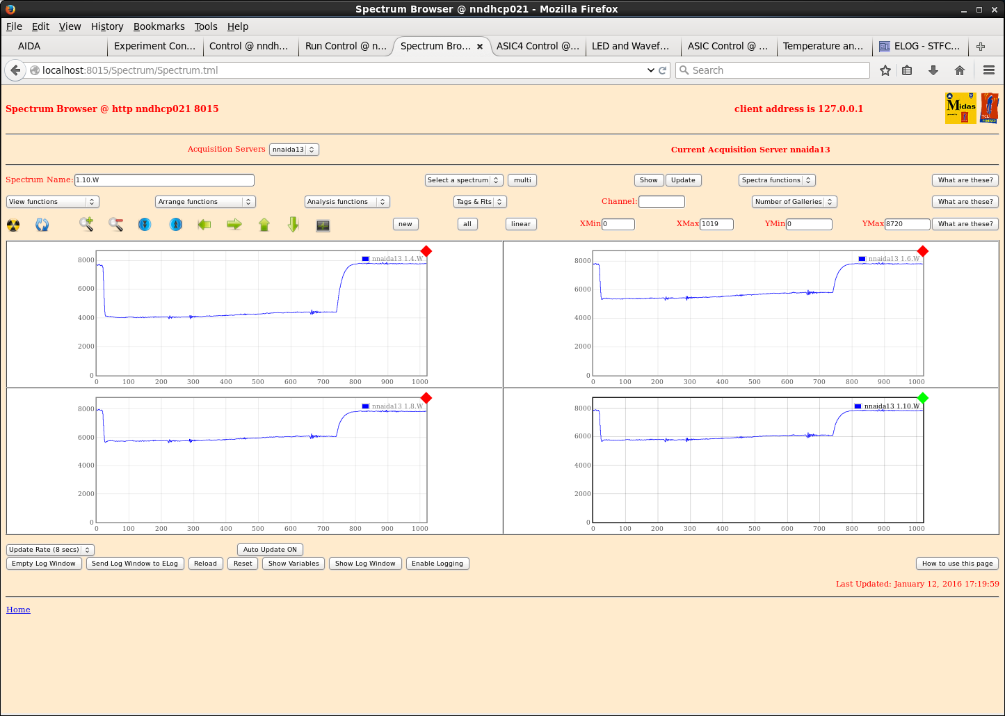
> thought it could possibly be due to pickup of external noise in the room so added Cu tape as shielding to cable connected to nnaida13 with drain wire connected to CU braid on pulser input
> reduced peak with in nnaida13 to ~160ch
> connecting far end of Cu shielding via a Cu braid to main Cu braid reduces this to ~130ch
> connecting Cu shielding on RH coupler to main ribbon cable shielding with thin braid reduced this further to ~110ch
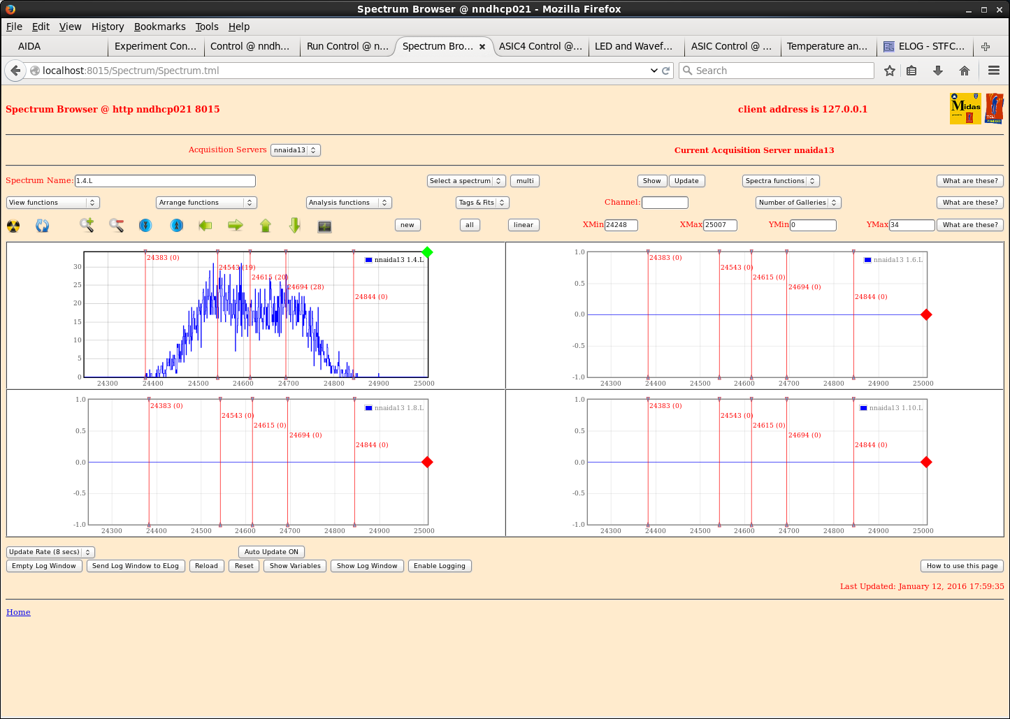
For nnaida13, see double peaking of pulser peak with all shaping times up to 2us. At 4us, see single peak of width ~160ch. At 8us, see single peak of width ~110ch.
13/01/16 (Attachments 9-20)
Set up system as yesterday.
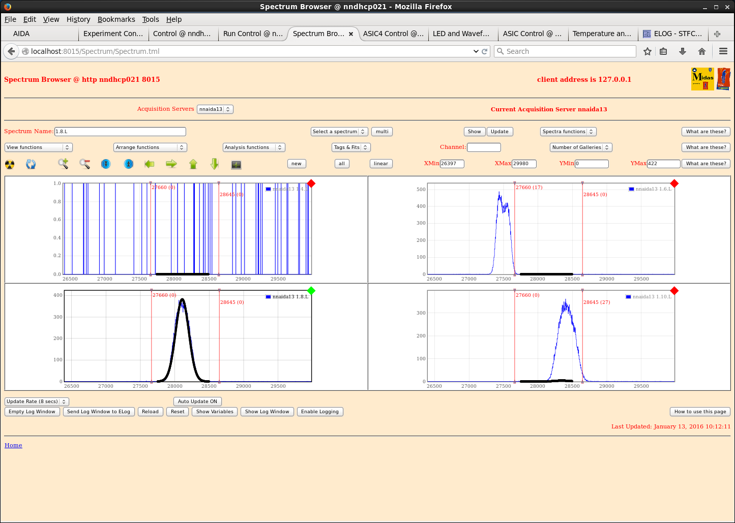
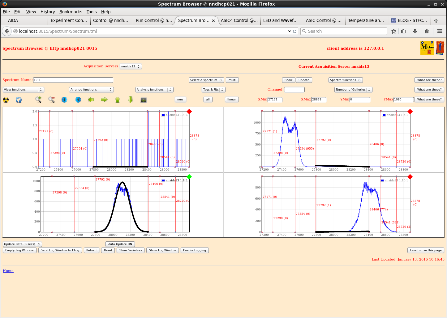
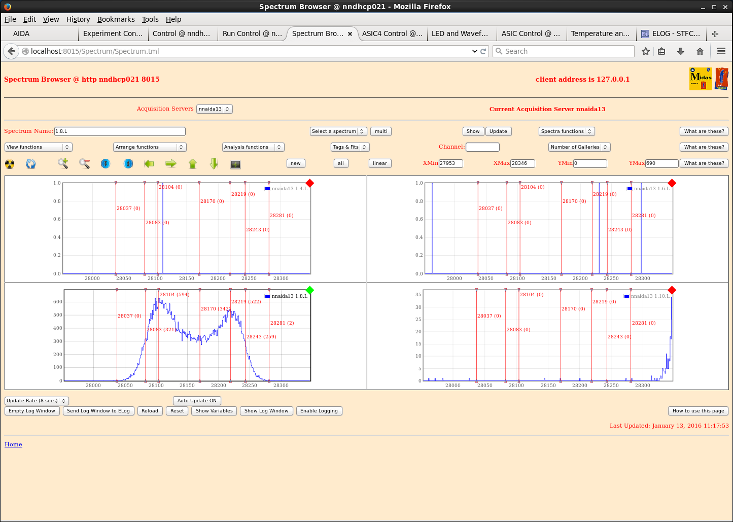
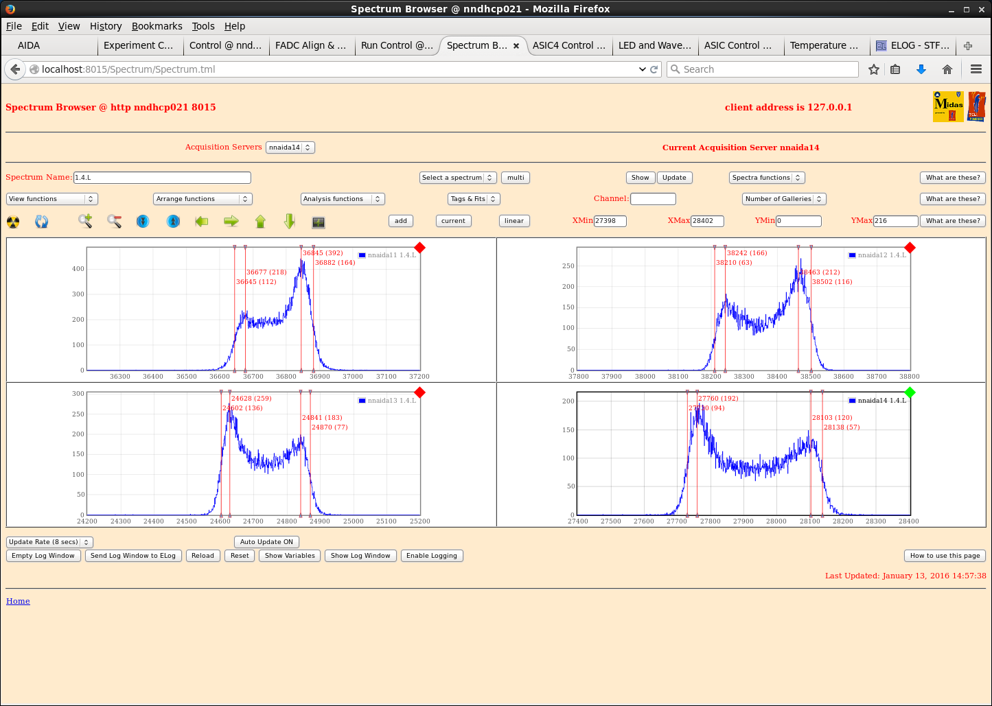
With shaping time of 2us, nnaida13 does not show Gaussian peaks. Some peaks are double, others just single non-Gaussian peaks.
Yesterday peak-to-peak difference was ~150ch
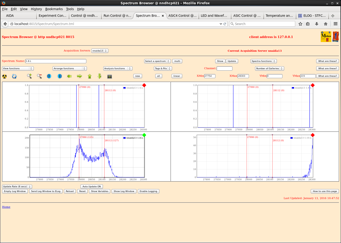
- added tin foil to loose coupler end and over connection between ribbon cable and RH coupler, as it was suspected it could be pickup of external noise
- @ 2us shaping time, double peaks still present with p-2-p difference of ~130ch
- clipped foil firmly to Cu shielding tape > no difference.
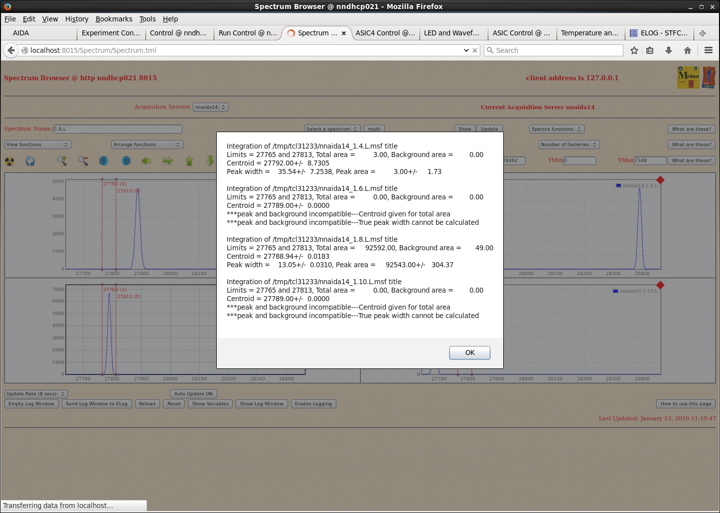
In nnaida14, see single roughly Gaussian peak of width ~15ch.
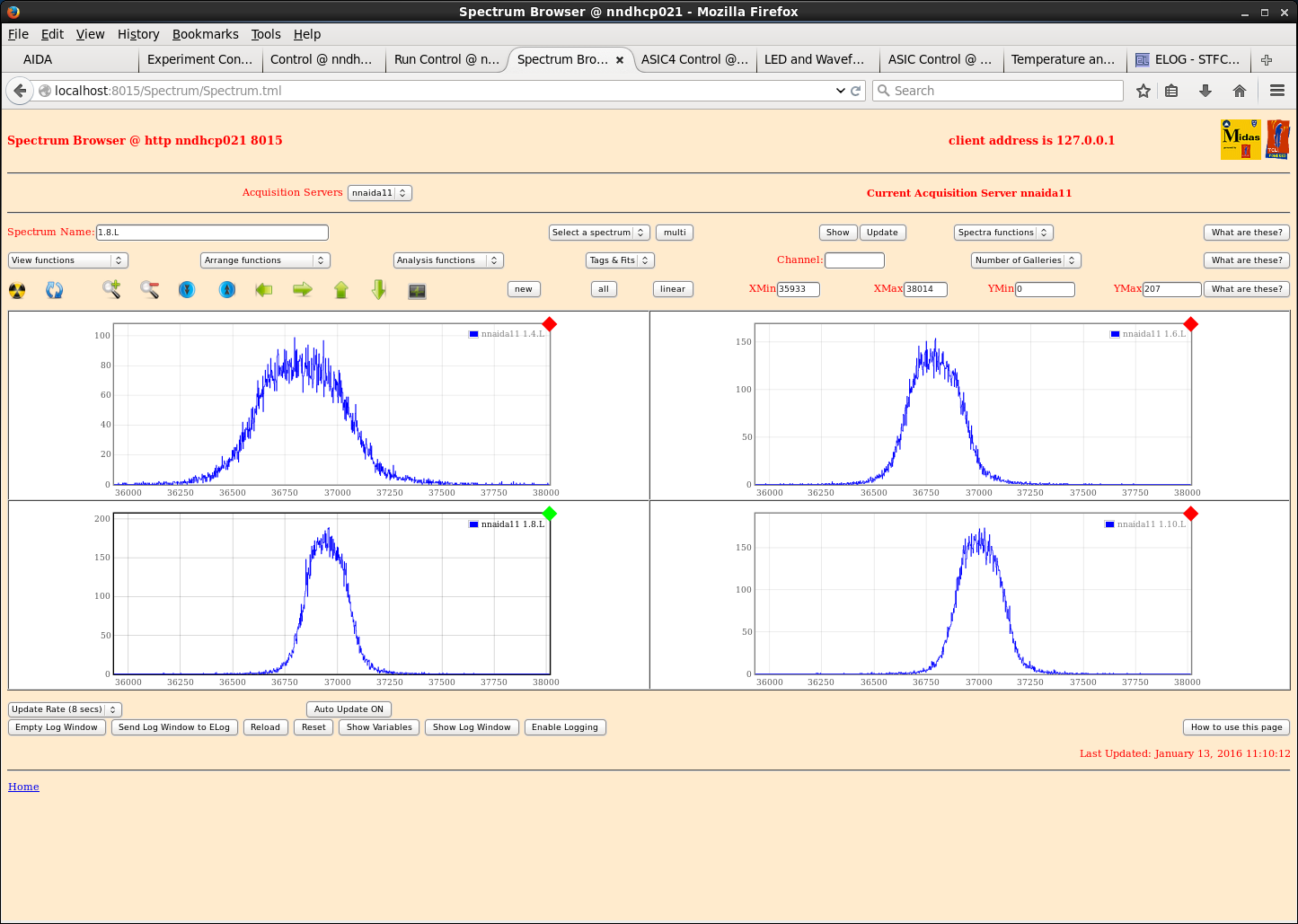
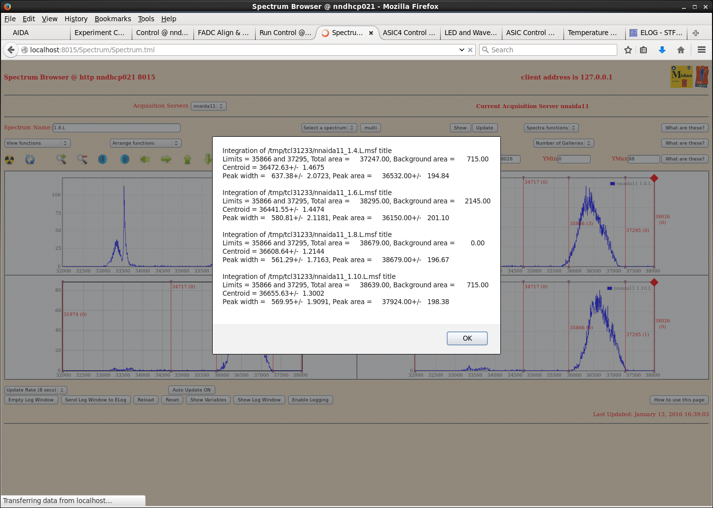
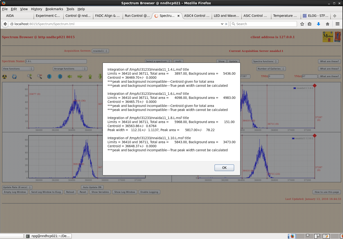
In nnaida11, see single peaks of widths ~250ch. At 8us this reduces to ~180ch.
Connecting the Lk7 jumper for nnaida13 produces no difference.
Added full LH coupler + 45cm ribbon + RH coupler to all nnaida, with full shielding > no improvement.
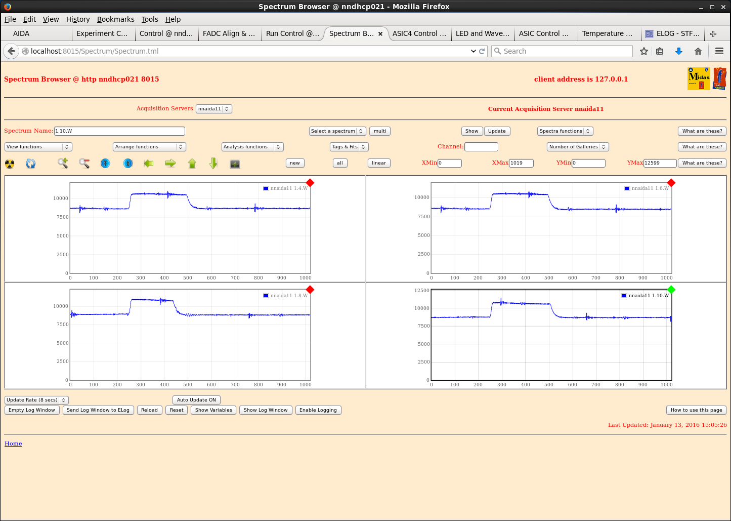
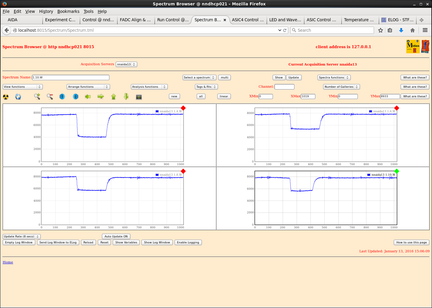
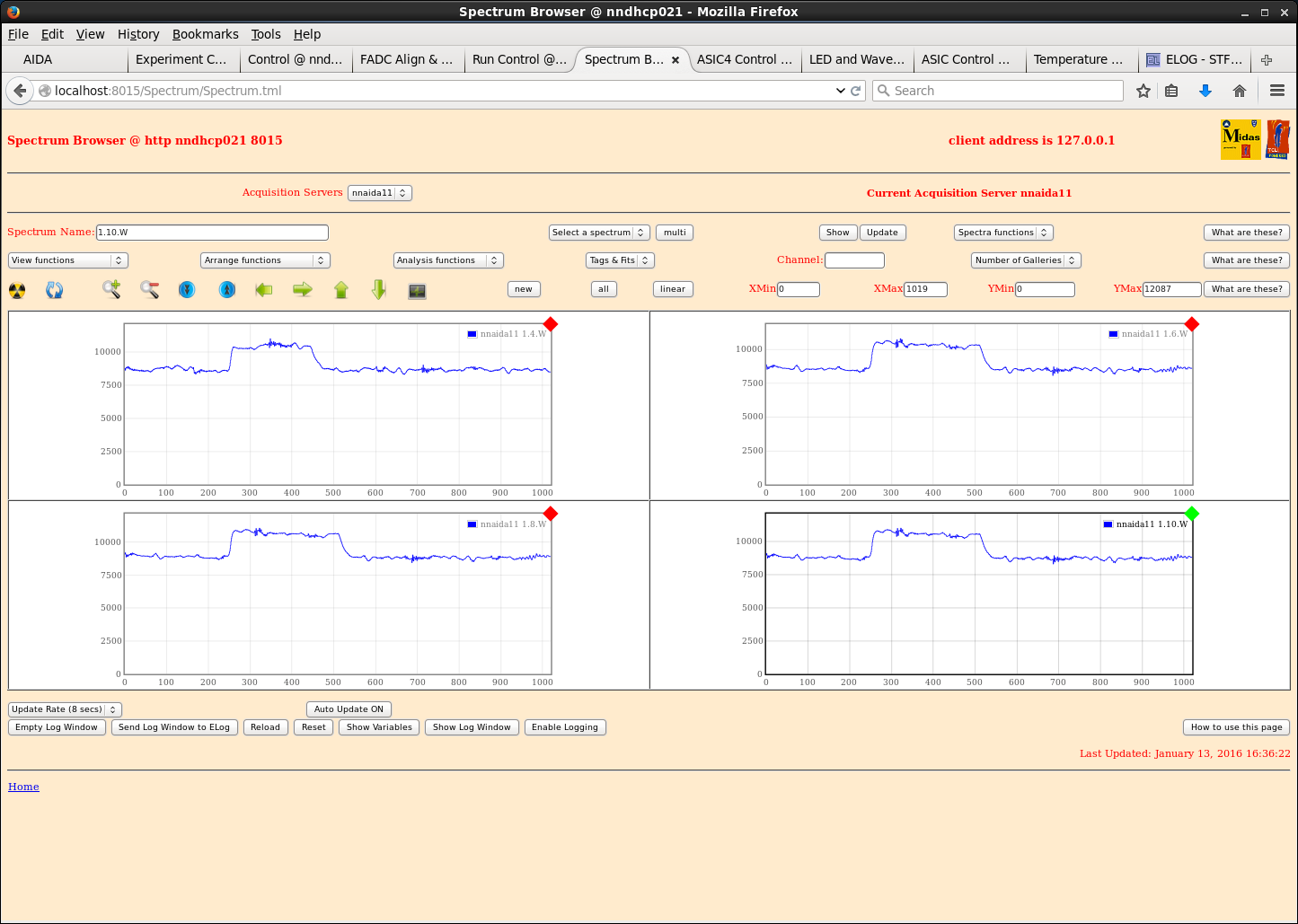
Connected all to detector and saw no improvements, in fact increased noise in nnaida13 dramatically (see waveforms)
See low frequency wave in waveforms, will work next week to try remove this as this could be what is causing the double peaking and hiding the true capabilities of the cables.
|
| Attachment 1: nnaida11-14_1.4_varyingCables.png
|
|
| Attachment 2: nnaida11_wav_LHcoupler45cmUnshielded.png
|
|
| Attachment 3: nnaida13_wav_LHcoupler45cmUnshieldedRHcoupler.png
|
|
| Attachment 4: nnaida14_wav_LHcoupler.png
|
|
| Attachment 5: nnaida13_wav_LH45cmShieldedRH.png
|
|
| Attachment 6: nnaida13_spec_LH45cmShieldedRH.png
|
|
| Attachment 7: nnaida13_spec_LH45cmShieldedRHshielded.png
|
|
| Attachment 8: nnaida13_spec_fullShieldedCable_2usShapingTime.png
|
|
| Attachment 9: nnaida13_spec_noGaussian.png
|
|
| Attachment 10: nnaida13_spec_nonGaussianDoubplePeaks.png
|
|
| Attachment 11: nnaida13_spec_cableEndFoilShielding.png
|
|
| Attachment 12: nnaida11_spec_1us.png
|
|
| Attachment 13: nnaida13_spec_1usFullyShielded.png
|
|
| Attachment 14: nnaida14_spec_1usLHcoupler.png
|
|
| Attachment 15: nnaidaAll_spec_all4CompleteShieldedCables_1us.png
|
|
| Attachment 16: nnaida11_wav_4CompleteShielded.png
|
|
| Attachment 17: nnaida13_wav_4CompleteShielded.png
|
|
| Attachment 18: nnaida11_wav_4CompleteShieldedCablesPlusDetector.png
|
|
| Attachment 19: nnaida11_spec_4CompleteShieldedCablesPlusDetector_1us.png
|
|
| Attachment 20: nnaida11_spec_4CompleteShieldedCablesPlusDetector_8us.png
|
|
|
|
139
|
Thu Jan 7 16:04:44 2016 |
CG, PJCS | PCS Reply to RIKEN progress - 15/12/15 (late) |
| Quote: |
|
Tues 15/12/15
Swapped previously tripped detector (3131-11) on to kaptons already in place for (working) 2977-15 and attempted to bias
- i.e. made no changes (FEEs, or jumpers etc) to the known working setup of 2977-15, just replaced the detector with 3131-11
> still trips at ~6-7V
> conclusion: He's dead Jim.
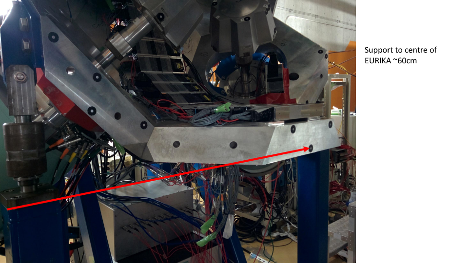
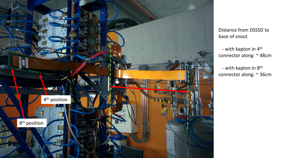
Took some measurements of rough max positions of DSSSDs from the FEEs with the current 90cm kaptons (pictures in attached PowerPoint and PDF)
- Vertical EURIKA support to centre of EURIKA ~ 60cm
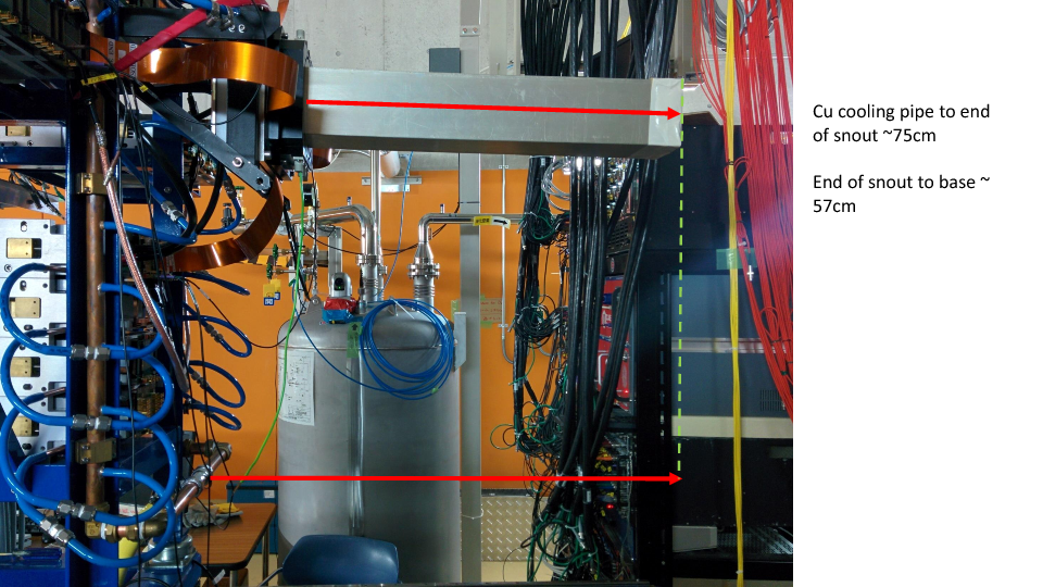
- AIDA Cu cooling pipe to end of snout ~ 75cm
- Base of snout to end = 57cm
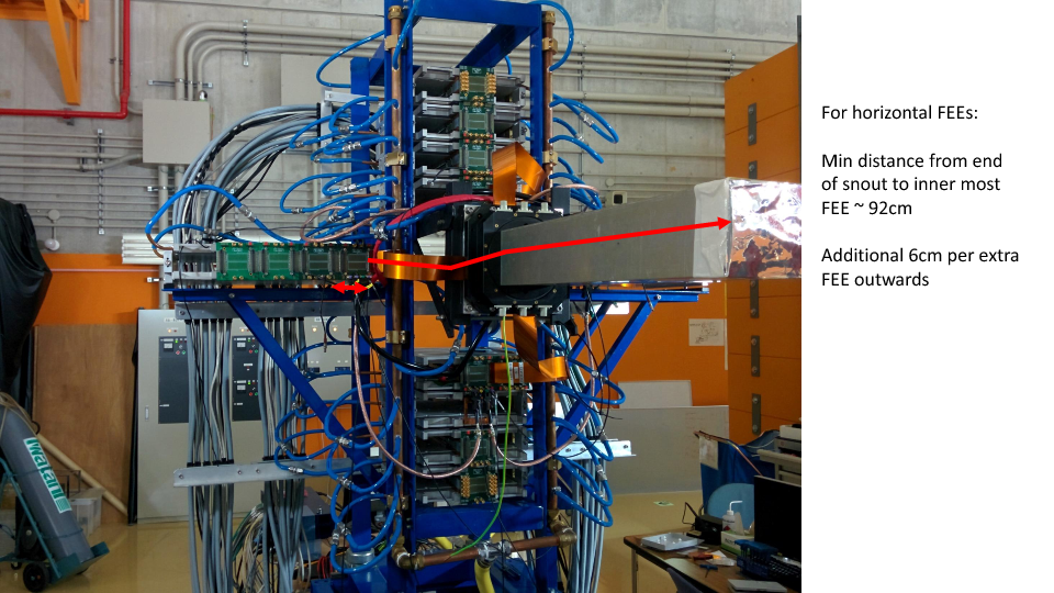
- Min distance from end of snout to inner most FEE (horizontal FEEs) ~ 92cm
- additional 6cm per extra adapter
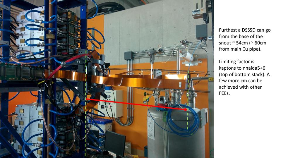
- Further DSSSD can go from base of snout ~ 54cm (60cm from Cu pipe)
- limiting factor is kaptons to nnaida5+6 (bottom stack). Still a few more cm slack in the other kaptons.
- For kaptons in 4th horizontal connector (furthest slot in 2nd adapter), detector 48cm from base of snout.
- For kaptons in 8th horizontal connector (furthest slot in 4th adapter), detector 36cm from base of snout.
Note (PCS): In disconnecting things to check ground connections, and when putting AIDA away before I left, I noticed ~20% of the network cables are of the shielded variety. I know this didn't seem to make any difference in the setup at DL, but I don't know how concerned you are about this and if you would suggest changing them in future.
|
I would recommend changing the network cables for unshielded versions to remove a potential ground connection. |
|
|
138
|
Thu Jan 7 13:55:24 2016 |
CG | RIKEN progress - 15/12/15 (late) |
Tues 15/12/15
Swapped previously tripped detector (3131-11) on to kaptons already in place for (working) 2977-15 and attempted to bias
- i.e. made no changes (FEEs, or jumpers etc) to the known working setup of 2977-15, just replaced the detector with 3131-11
> still trips at ~6-7V
> conclusion: He's dead Jim.
Took some measurements of rough max positions of DSSSDs from the FEEs with the current 90cm kaptons (pictures in attached PowerPoint and PDF)
- Vertical EURIKA support to centre of EURIKA ~ 60cm
- AIDA Cu cooling pipe to end of snout ~ 75cm
- Base of snout to end = 57cm
- Min distance from end of snout to inner most FEE (horizontal FEEs) ~ 92cm
- additional 6cm per extra adapter
- Further DSSSD can go from base of snout ~ 54cm (60cm from Cu pipe)
- limiting factor is kaptons to nnaida5+6 (bottom stack). Still a few more cm slack in the other kaptons.
- For kaptons in 4th horizontal connector (furthest slot in 2nd adapter), detector 48cm from base of snout.
- For kaptons in 8th horizontal connector (furthest slot in 4th adapter), detector 36cm from base of snout.
Note (PCS): In disconnecting things to check ground connections, and when putting AIDA away before I left, I noticed ~20% of the network cables are of the shielded variety. I know this didn't seem to make any difference in the setup at DL, but I don't know how concerned you are about this and if you would suggest changing them in future.
|
| Attachment 1: AIDA_measurements_-_Dec2015.pdf
|
|
| Attachment 2: AIDA_measurements_-_Dec2015.pptx
|
|
|
137
|
Wed Jan 6 16:06:32 2016 |
CG, TD, PJCS | Report: Low - RPi power cable can't be fully inserted due to case conflict - solved |
| Quote: |
|
The RPi power cable cannot sit fully in the connector, and the lock pins can't engage, because the case gets in the way of the plastic around the end.
As a result we have knocked it out a couple of times and lost power to the system.
Can this be modified or can we get a new case/cable that resolves this issue?
|
The case has been changed for one that doesn't allow the power cable to be easily extracted. |
|
|
136
|
Tue Dec 15 11:17:05 2015 |
TD | STFC DL tests - 14-15.12.15 |
BNC PB-5 Pulser

Fall time 1.0ms
Rate 100Hz
Delay 250ns
Ampl 5.0V
Polarity +
Pulse Top Tail
Atten 10x
PB-5 Pulse ON
Clamp ON

- polarity via Cooknell SA1 Summing Amplifier

nnaida11 & 12 AIDA adaptor rev C (280114) LK1 jumper fitted
nnaida13 & 14 AIDA adaptor rev B (180713)

Heavy duty Cu braid and large clips connect BNC connectors of
cabling to test inputs of both adaptor PCBs.

Heavy duty Cu braid connects Cu mezzanines of nnaida11 & 14

Standard ASIC settings
nnaida11 & 12 - input, nnaida13 & 14 + input
shaping time 8us
fast discriminators 0xff
slow comparator 0x40

***

Zero input load

         nnaida11 nnaida12 nnaida13 nnaida14
1.4.L    14.63    14.88    15.95    13.03
1.6.L    14.35    15.01    13.47    12.62
1.8.L    14.86    14.54    12.88    13.43
1.10.L   14.67    13.76    13.03    13.43

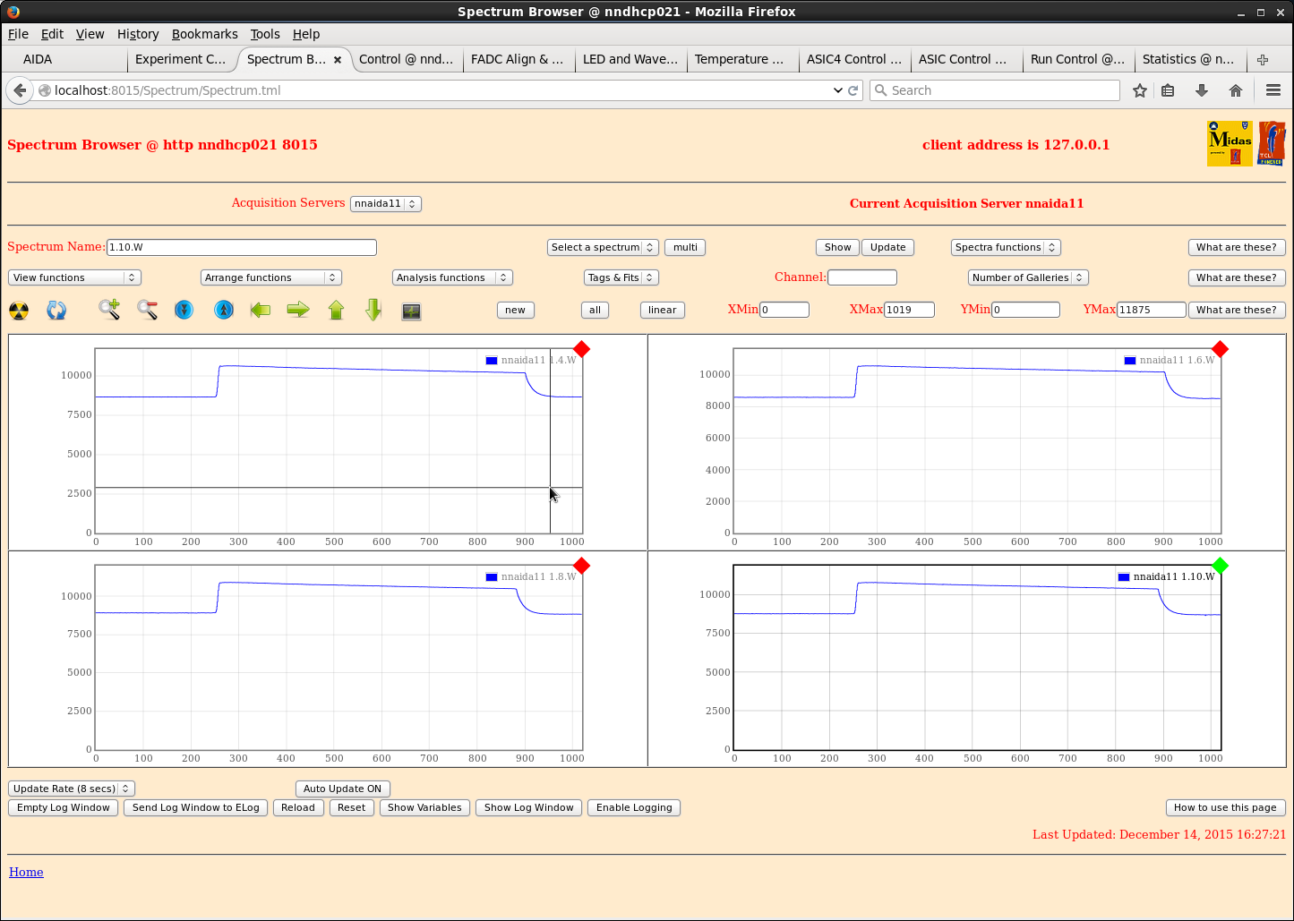
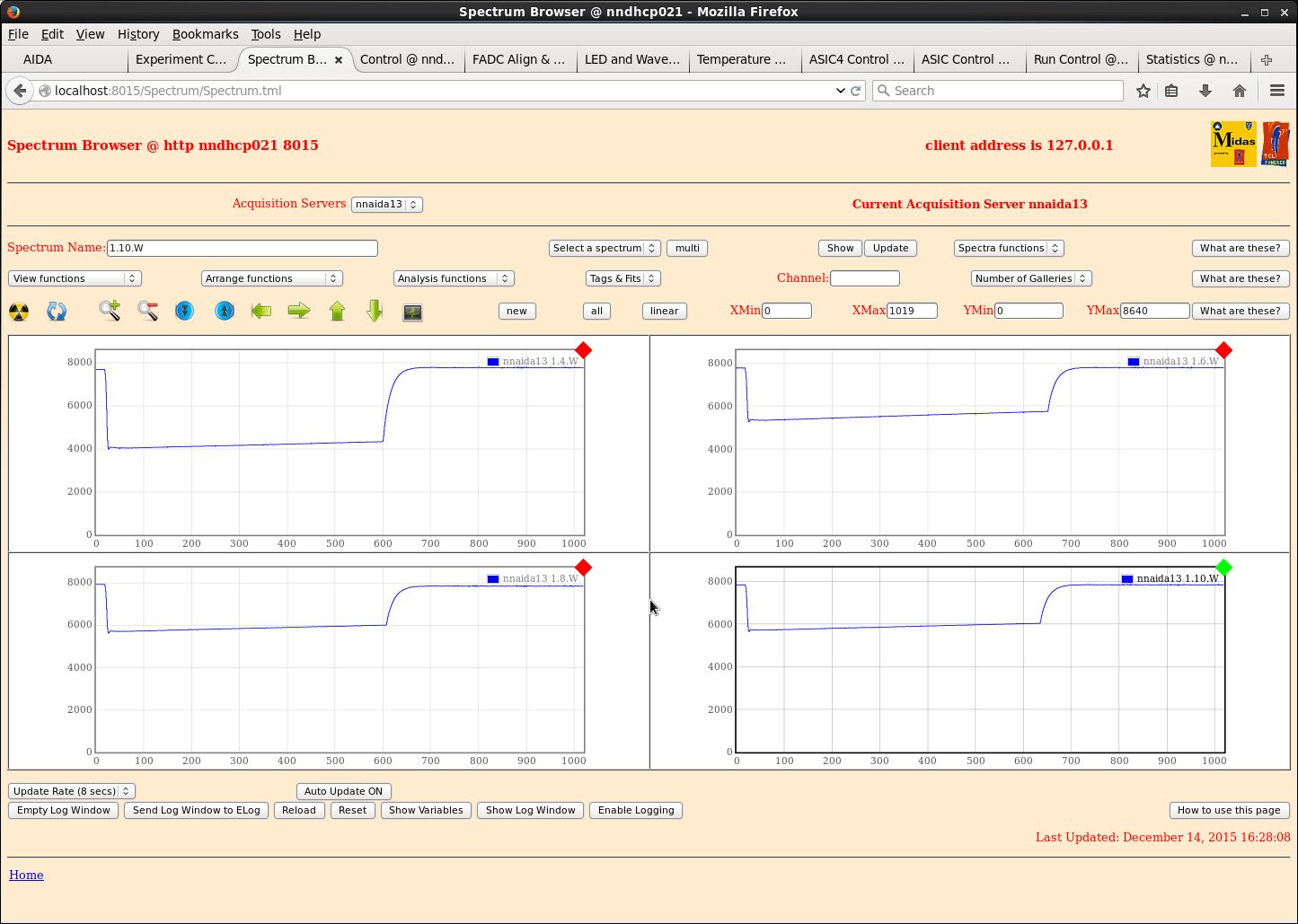
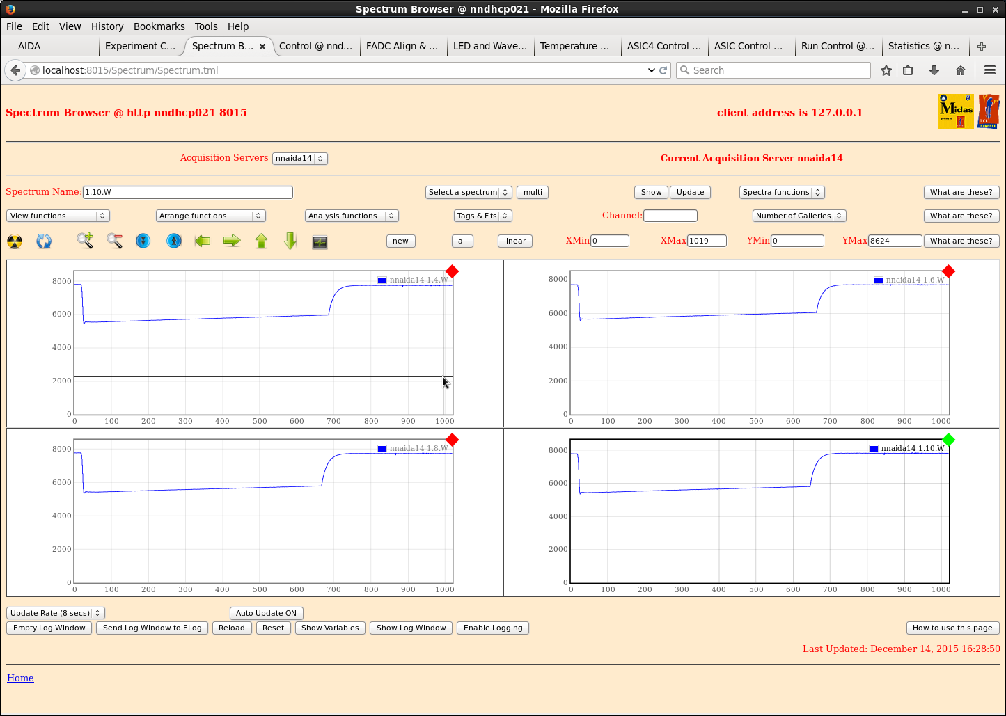
See attachments 1-3

***

Left hand coupler (011215) nnaida11 & 14 (only)
No EMC shielding or grounding

         nnaida11 nnaida12 nnaida13 nnaida14
1.4.L    33.64    16.02    15.34    18.74
1.6.L    23.92    14.92    12.98    14.00
1.8.L    17.09    14.36    13.07    13.63
1.10.L   16.66    14.67    13.27    13.92

Left hand coupler (011215) nnaida11 & 14
No EMC shielding or grounding

***

Left hand coupler (011215) + 1x 45cm 34-way ribbon cable nnaida13
Left hand coupler (011215) + 1x 90cm 34-way ribbon cable nnaida12
No EMC shielding or grounding

         nnaida11 nnaida12 nnaida13 nnaida14
1.4.L    30.37    19.41    23.02    21.15
1.6.L    21.64    16.99    17.73    15.82
1.8.L    16.85    16.43    14.14    14.78
1.10.L   16.31    16.70    13.07    13.75
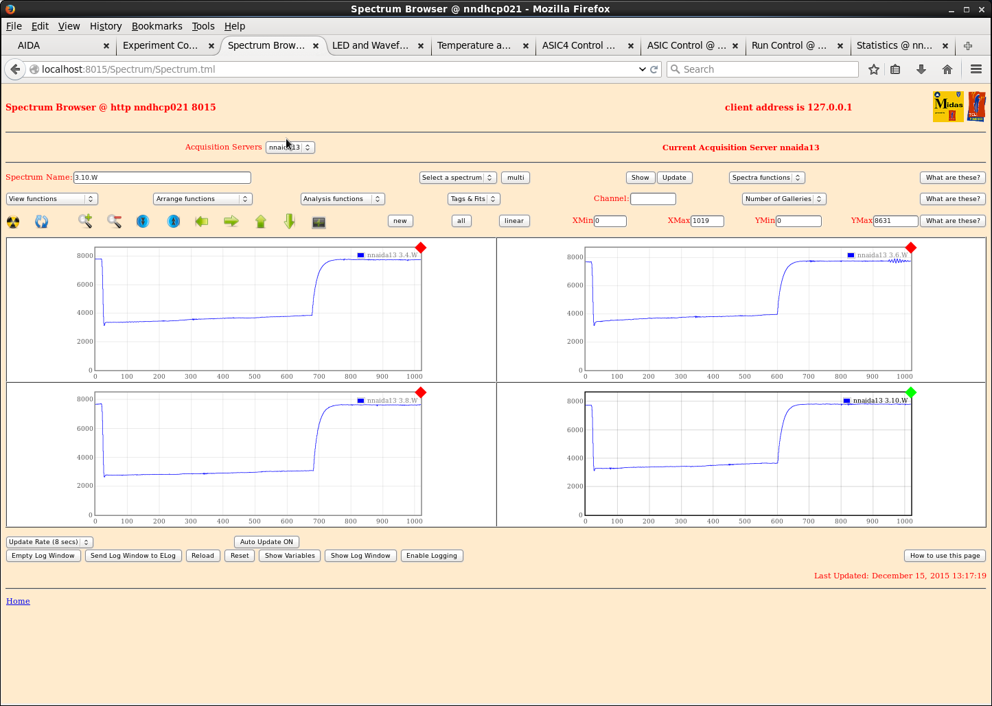
3.4.L    16.13    650      122.61   14.76
3.6.L    15.98    710      140.07   14.32
3.8.L    16.53    610      111.10   14.36
3.10.L   17.05    630      121.59   14.26

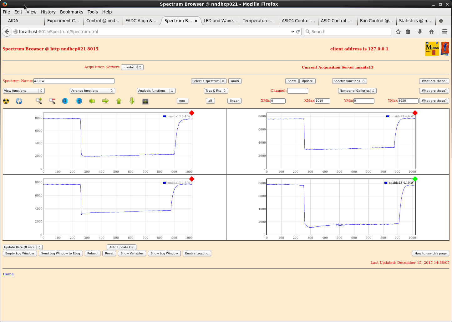
See attachment 4 - are these actually 3*W waveforms?

***

Left hand coupler (011215) + 1x 45cm 34-way ribbon cable nnaida11
Left hand coupler (011215) + 1x 90cm 34-way ribbon cable nnaida12

Left hand coupler (011215) + 1x 90cm 34-way ribbon cable nnaida14
Left hand coupler (011215) + 1x 45cm 34-way ribbon cable nnaida13

No EMC shielding or grounding

         nnaida11 nnaida12 nnaida13 nnaida14
1.4.L    27.44    18.70    21.79    20.32
1.6.L    19.84    16.90    17.06    16.06
1.8.L    16.20    15.73    14.06    19.34
1.10.L   16.23    16.42    14.27    17.11
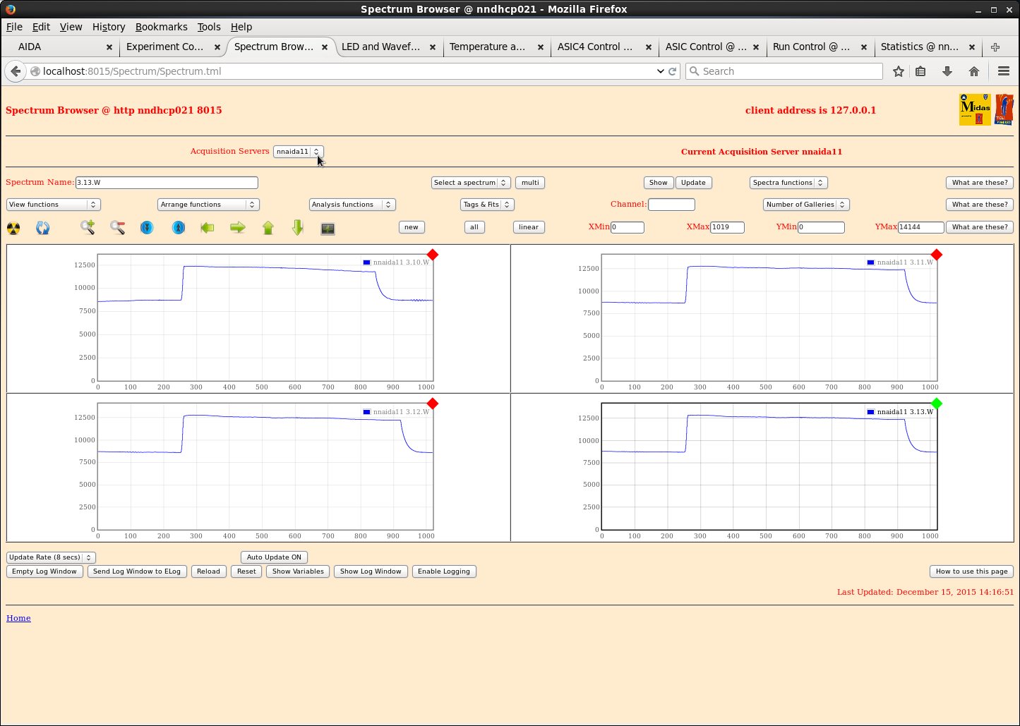
3.4.L    146.47   510      91.03    390
3.6.L    160.69   555      105.11   640
3.8.L    142.32   490      85.85    370
3.10.L   144.06   510      93.30    390

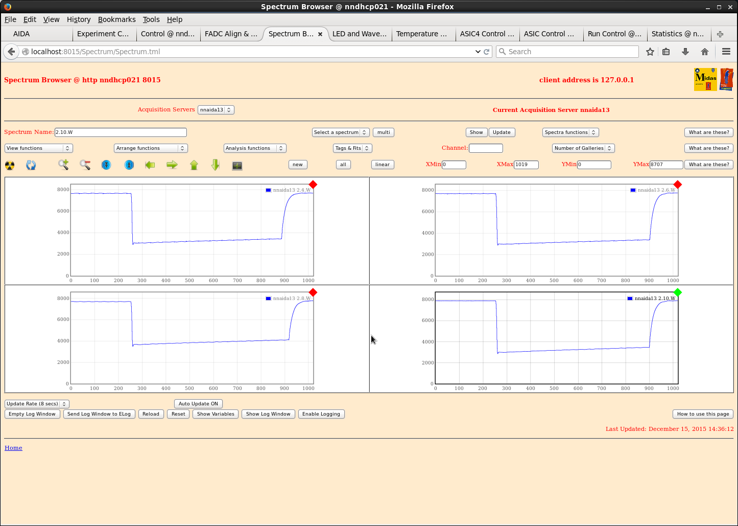
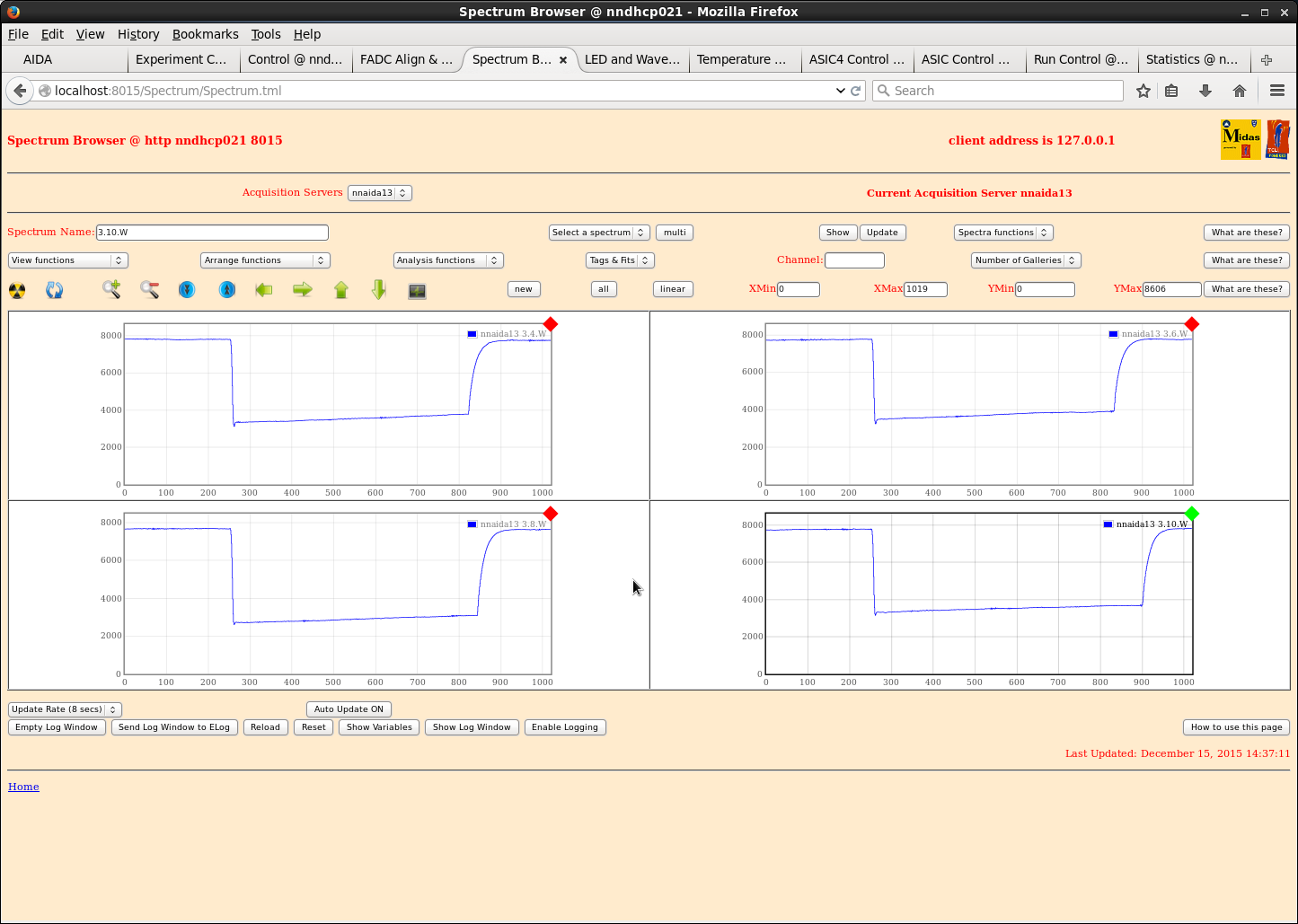
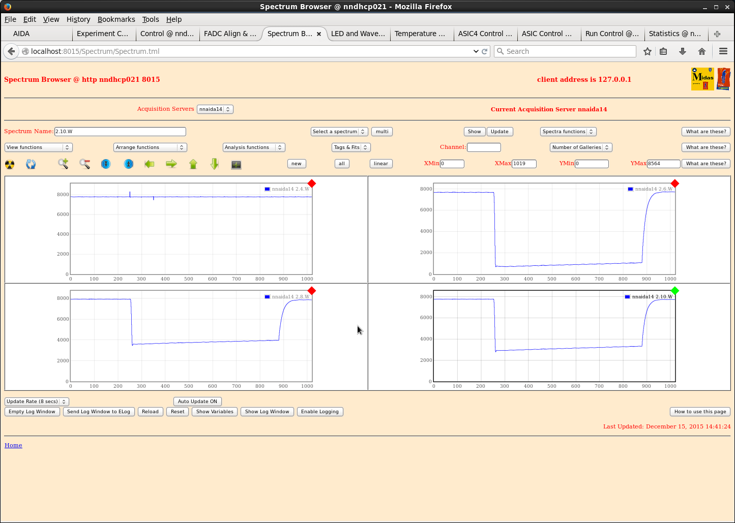
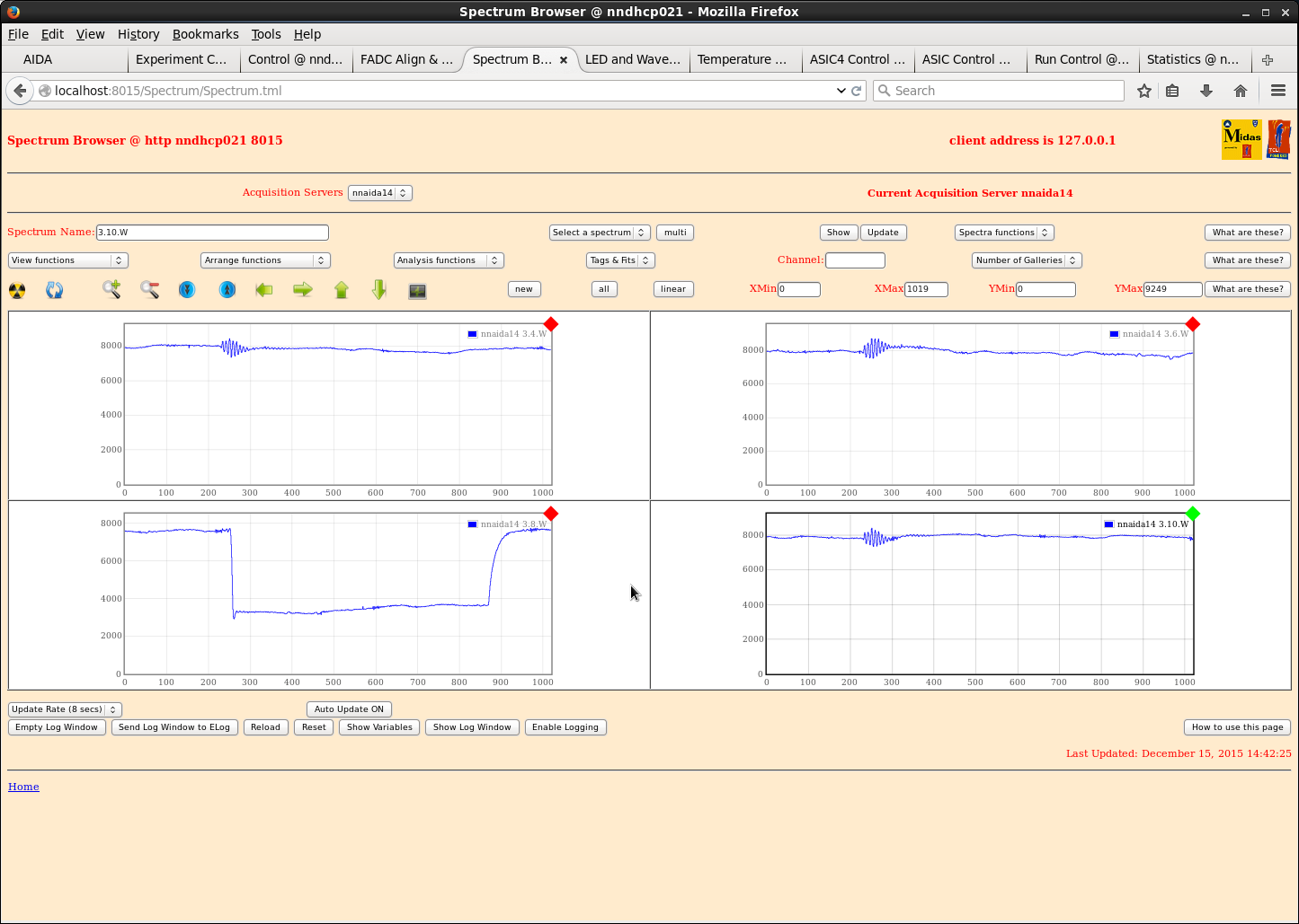
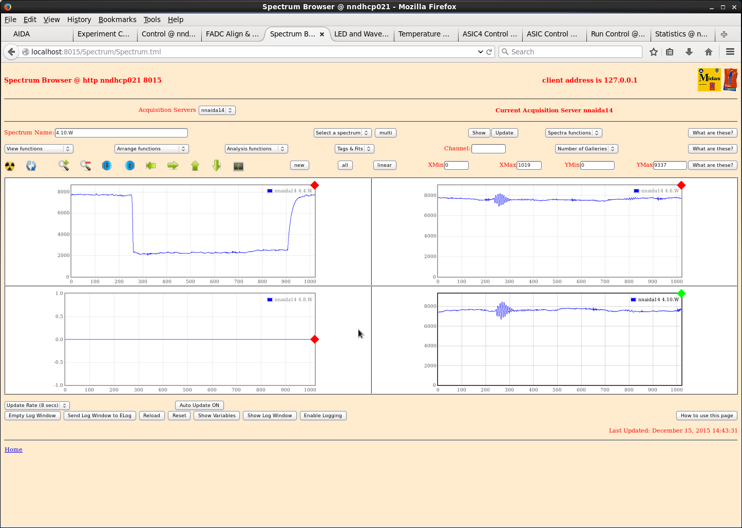
See attachments 5-13

***

Shaping time 2us

         nnaida11 nnaida12 nnaida13 nnaida14
1.4.L                               19.60
1.6.L                               15.67
1.8.L                               17.68
1.10.L                              15.88
3.4.L    160.95   560      90.85    550
3.6.L    173.91   600      108.19   865
3.8.L    155.90   535      88.35    460
3.10.L 162.21 560 95.45 540 |
| Attachment 1: nnaida_1*W.png
|
|
| Attachment 2: nnaida13_1*W.png
|
|
| Attachment 3: nnaida14_1*W.png
|
|
| Attachment 4: nnaida13_3*W.png
|
|
| Attachment 5: nnaida11_3*W.png
|
|
| Attachment 6: nnaida13_1*W.png
|

|
| Attachment 7: nnaida13_2*W.png
|
|
| Attachment 8: nnaida13_3*W-2.png
|
|
| Attachment 9: nnaida13_4*W.png
|
|
| Attachment 10: nnaida14_1*W.png
|

|
| Attachment 11: nnaida14_2*W.png
|
|
| Attachment 12: nnaida14_3*W.png
|
|
| Attachment 13: nnaida14_4*W.png
|
|
|
|
135
|
Mon Dec 14 19:25:35 2015 |
AE, CG ,Phong | Merger/TapeServer trouble report |
Sat. 12/12/15

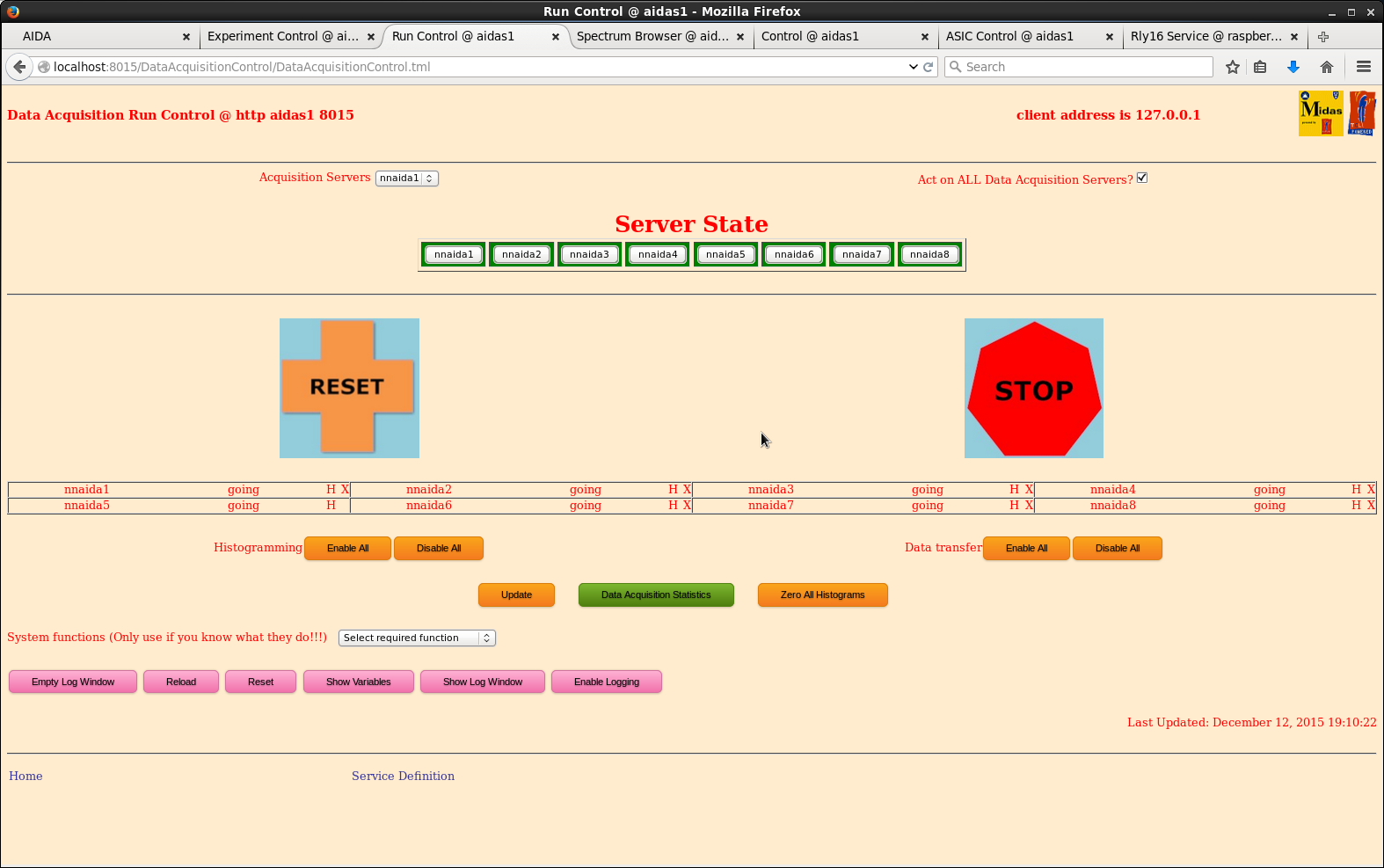
Working with a 8-FEE setup (as in https://elog.ph.ed.ac.uk/AIDA/133). We could open a file with the
TapeServer. Merger also seems to be working (cursor spinning, and merge statistics ~ok). However the
TapeServer doesn’t write anything to disk (just empty an file).

A few observations; I only took ‘systematic’ notes after we had reduced the number of FEEs to 8, but it's
likely we were also facing the same problems before with a full system:

+ When enabling data transfer from NNAIDA modules (in Run Control page), it switches to the right mode for
all FEEs except for NNAIDA5. NNAIDA5 is the master FEE. The merger also doesn’t show any stats for NNAIDA5
(but stats look ok for all other FEEs). The spectra for NNAIDA5 look ok, so the FEE is generating data.

+ A few times we observe the following behavior: DAQ running without trouble. We start Merger+TapeServer,
and when attempting some actions in RunControl (start-stop, or reset), we loose the ability to communicate
with a number of FEEs. These FEEs can not perform a ReSYNC, and the only way to get them back to life is
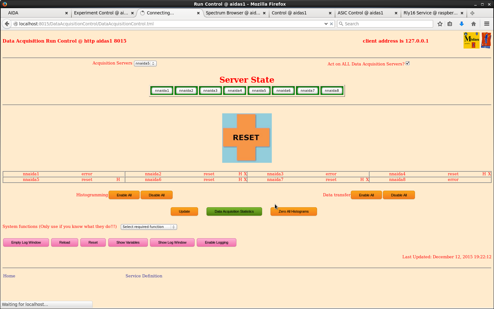
going through a power cycle. It seems like the TaperServer or Merger is somehow upsetting the FEEs or the
DAQ. We can still ‘ping’ all FEEs, even after the ‘connect failed’ message.

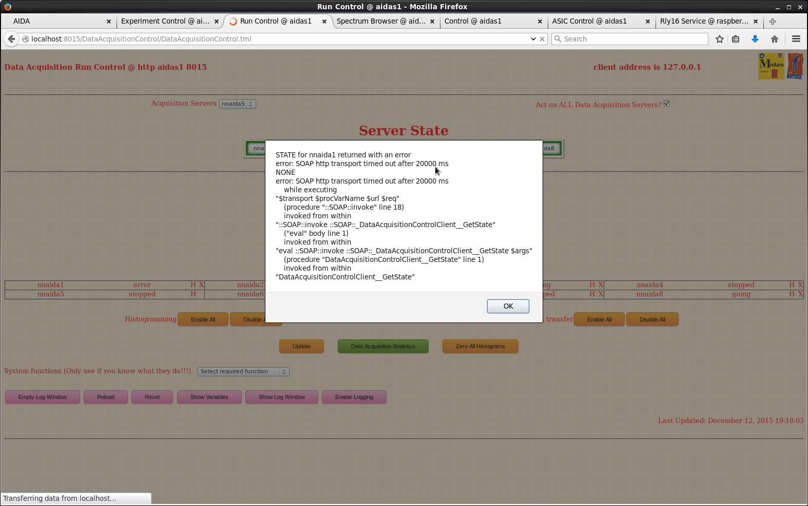
Attached are a few screenshots, and the text in the terminals for Merger and TapeServer. The following is
the error returned by one FEE when we can’t ReSync them:


STATE for nnaida3 returned with an error
connect failed
NONE
connect failed
    while executing
"::http::geturl http://nnaida3:8015/DataAcquisitionControlServer -headers {} -type text/xml -timeout 20000
-query {<?xml version="1.0" encoding="UTF-8"..."
    ("eval" body line 1)
    invoked from within
"eval [list ::http::geturl $url] $args"
    (procedure "::http::geturl_followRedirects" line 4)
    invoked from within
"::http::geturl_followRedirects http://nnaida3:8015/DataAcquisitionControlServer -headers {} -type
text/xml -timeout 20000 -query {<?xml version="1.0" ..."
    ("eval" body line 1)
    invoked from within
"eval ::http::geturl_followRedirects [list $url]  -headers [list $local_headers]  -type text/xml  -timeout
$timeout  -query [list $request]  $local_pro..."
    (procedure "::SOAP::Transport::http::xfer" line 61)
    invoked from within
"$transport $procVarName $url $req"
    (procedure "::SOAP::invoke" line 18)
    invoked from within
"::SOAP::invoke ::SOAP::_DataAcquisitionControlClient__GetState"
    ("eval" body line 1)
    invoked from within
"eval ::SOAP::invoke ::SOAP::_DataAcquisitionControlClient__GetState $args"
    (procedure "DataAcquisitionControlClient__GetState" line 1)
    invoked from within
"DataAcquisitionControlClient__GetState"
GET OPTION for nnaida3 returned with an error
connect failed
NONE
connect failed
    while executing
"::http::geturl http://nnaida3:8015/DataAcquisitionControlServer -headers {} -type text/xml -timeout 60000
-query {<?xml version="1.0" encoding="UTF-8"..."
    ("eval" body line 1)
    invoked from within
"eval [list ::http::geturl $url] $args"
    (procedure "::http::geturl_followRedirects" line 4)
    invoked from within
"::http::geturl_followRedirects http://nnaida3:8015/DataAcquisitionControlServer -headers {} -type
text/xml -timeout 60000 -query {<?xml version="1.0" ..."
    ("eval" body line 1)
    invoked from within
"eval ::http::geturl_followRedirects [list $url]  -headers [list $local_headers]  -type text/xml  -timeout
$timeout  -query [list $request]  $local_pro..."
    (procedure "::SOAP::Transport::http::xfer" line 61)
    invoked from within
"$transport $procVarName $url $req"
    (procedure "::SOAP::invoke" line 18)
    invoked from within
"::SOAP::invoke ::SOAP::_DataAcquisitionControlClient__GetOption NetVar=NetVar.DACQ.Chistenable"
    ("eval" body line 1)
    invoked from within
"eval ::SOAP::invoke ::SOAP::_DataAcquisitionControlClient__GetOption $args"
    (procedure "DataAcquisitionControlClient__GetOption" line 1)
    invoked from within
"DataAcquisitionControlClient__GetOption "$AcqGetOption"" |
| Attachment 1: master_no_data_transfer.png
|
|
| Attachment 2: master_no_data_transfer.png
|

|
| Attachment 3: error_when_stop_daq_merger_running.png
|
|
| Attachment 4: error_show_1_3_8_kaput.png
|
|
| Attachment 5: out_term.txt
|
=> "Httpd for Merger/Tape Server" terminal:


System identified is CPU x86_64; Platform is unix; OS is Linux and Version is 2.6.32-504.8.1.el6.x86_64
Environment selected is CPU x64_64; Platform unix; OS Linux64 and Operating System Linux64
MIDASBASE = /MIDAS@aidas and MIDAS_LIBRARY = /MIDAS@aidas/TclHttpd/Linux64
PATH = /MIDAS@aidas/bin_Linux64:/MIDAS@aidas/TclHttpd/Linux64:/homes/npg/root/bin:/homes/npg/root/bin:/homes/npg/root/lib:/MIDAS/Linux/bin64:/usr/lib64/qt-3.3/bin:/usr/local/bin:/usr/bin:/bin
package limit is not available: can't find package limit
Running with default file descriptor limit
package setuid is not available: can't find package setuid
Could not change to user 50 group 50: not owner
/debug user "debug" password "aegc.ur9z+3w"
httpd started on port 8115

Custom startup from /MIDAS@aidas/config/TclHttpd/aidas1@8115/startup.tcl
/TapeServer
/DataBaseAccessServer
Loaded MemSasAccess
/SpectrumService
/NetVarService
/SigTaskService
loading tcl/MERGERunControl.tcl for namespace ::
/DataAcquisitionControlServer
DefineMessage unknown
Run Control Server Implementation for MERGE
RunControlServer loaded
loading Html/RunControl/implementation.tcl for namespace ::
RunControl loaded
loading Html/MERGE/RunControl/implementation.tcl for namespace ::
ReadRegister failed: Name=NetVar.EXEC.ID; Code= 0x10004; Info= Register name does not exist
created SigTask registers 0 0  0 0
Created UI registers
MERGE RunControl loaded
Completed custom startup from /MIDAS@aidas/TclHttpd/Html/MERGE/RunControl/stats.defn.tcl
Shared memory area located at 0x7f6b51f67000
Tape Server comms table located at 0x7f6b51f67000
setup Merge
DataAcqCommand: 1 Halt
Halt (1)
DataAcqCommand: 8 Unmapping spectra
Unmapping spectra (1)
DataAcqCommand: 3 Setup
Setup (1)
go Merge
DataAcqCommand: 3 connect xfer stream
connect xfer stream (1)
DataAcqCommand: 2 Go
Go (1)
DataAcqCommand: 16 MergeStart
MergeStart (1)


=> "Merger" terminal:
.
.
.
MERGE Data Link (25178): Started with args 27 11000 11028
MERGE Data Link (25170): MIDAS MERGE Data Link Build Aug 12 2014
MERGE Data Link (25178): Configuration: index = 27, SHM key=11000, TCP port = 11028
MERGE Data Link (25178): File mapped object /SHM_11000 accessed
MERGE Data Link (25178): Shared memory ID is 3
MERGE Data Link (25178): Memory mapping 402732 bytes
MERGE Data Link (25178): Shared memory segment located at address 0x7f9815f0a000.
MERGE Data Link (25178): File mapped object /SHM_11001 accessed
MERGE Data Link (25178): Shared memory ID is 3
MERGE Data Link (25178): Memory mapping 1073741824 bytes
MERGE Data Link (25178): Shared memory segment located at address 0x7f97d5f0a000.
MERGE Data Link (25172): Message Initialisation failed.
MERGE Data Link (25172): Message logger not contacted.
MERGE Data Link (25181): Message Initialisation failed.
MERGE Data Link (25181): Message logger not contacted.
MERGE Data Link (25170): Started with args 19 11000 11020
MERGE Data Link (25170): Configuration: index = 19, SHM key=11000, TCP port = 11020
MERGE Data Link (25170): File mapped object /SHM_11000 accessed
MERGE Data Link (25170): Shared memory ID is 3
MERGE Data Link (25170): Memory mapping 402732 bytes
MERGE Data Link (25170): Shared memory segment located at address 0x7f5e73f1b000.
MERGE Data Link (25170): File mapped object /SHM_11001 accessed
MERGE Data Link (25170): Shared memory ID is 3
MERGE Data Link (25170): Memory mapping 1073741824 bytes
MERGE Data Link (25170): Shared memory segment located at address 0x7f5e33f1b000.
MRGE Stats created and initialised
MERGE Data Link (25153): Starting the network interface
MERGE Data Link (25153): TCP socket receive buffer was 87380 - now 249856
MERGE Data Link (25153): TCP socket send buffer was 16384 - now 249856
MERGE Data Link (25153): MERGE Data Link using TCP port 11003.
MERGE Data Link (25153): Entering server loop
MERGE Data Link (25153): listening on port 11003
MERGE Data Link (25180): Started with args 29 11000 11030
MERGE Data Link (25180): Configuration: index = 29, SHM key=11000, TCP port = 11030
MERGE Data Link (25180): File mapped object /SHM_11000 accessed
MERGE Data Link (25180): Shared memory ID is 3
MERGE Data Link (25180): Memory mapping 402732 bytes
MERGE Data Link (25180): Shared memory segment located at address 0x7fdf8abed000.
MERGE Data Link (25180): File mapped object /SHM_11001 accessed
MERGE Data Link (25180): Shared memory ID is 3
MERGE Data Link (25180): Memory mapping 1073741824 bytes
MERGE Data Link (25180): Shared memory segment located at address 0x7fdf4abed000.
MERGE Data Link (25172): MIDAS MERGE Data Link Build Aug 12 2014
MERGE Program (25183): Message Initialisation failed.
MERGE Program (25183): Message logger not contacted.
MERGE Program (25183): MIDAS MERGE Program (64-bit) Build Sep  3 2014
MERGE Program (25183): Started with args 11000
MERGE Program (25183): Configuration: SHM key=11000
MERGE Program (25183): File mapped object /SHM_11000 accessed
MERGE Program (25183): Shared memory ID is 3
MERGE Program (25183): Memory mapping 402732 bytes
MERGE Program (25183): Shared memory segment located at address 0x7f520d167000.
MERGE Program (25183): File mapped object /SHM_11001 accessed
MERGE Program (25183): Shared memory ID is 3
MERGE Program (25183): Memory mapping 1073741824 bytes
MERGE Program (25183): Shared memory segment located at address 0x7f51cd167000.
Creating NetVars #2
MERGE Data Link (25181): MIDAS MERGE Data Link Build Aug 12 2014
MERGE Data Link (25172): Started with args 21 11000 11022
MERGE Data Link (25172): Configuration: index = 21, SHM key=11000, TCP port = 11022
MERGE Data Link (25172): File mapped object /SHM_11000 accessed
MERGE Data Link (25172): Shared memory ID is 3
MERGE Data Link (25172): Memory mapping 402732 bytes
MERGE Data Link (25172): Shared memory segment located at address 0x7ff8a4728000.
MERGE Data Link (25172): File mapped object /SHM_11001 accessed
MERGE Data Link (25172): Shared memory ID is 3
MERGE Data Link (25172): Memory mapping 1073741824 bytes
MERGE Data Link (25172): Shared memory segment located at address 0x7ff864728000.
Output buffer length = 65504; format option = 4; transfer option = 3
NetVars created and initialised
MRGE Stats created and initialised
MERGE Data Link (25157): Starting the network interface
MERGE Data Link (25157): TCP socket receive buffer was 87380 - now 249856
MERGE Data Link (25157): TCP socket send buffer was 16384 - now 249856
MERGE Data Link (25157): MERGE Data Link using TCP port 11007.
MERGE Data Link (25157): Entering server loop
MERGE Data Link (25157): listening on port 11007
MRGE Stats created and initialised
MERGE Data Link (25160): Starting the network interface
MERGE Data Link (25160): TCP socket receive buffer was 87380 - now 249856
MERGE Data Link (25160): TCP socket send buffer was 16384 - now 249856
MERGE Data Link (25160): MERGE Data Link using TCP port 11010.
MERGE Data Link (25160): Entering server loop
MERGE Data Link (25160): listening on port 11010
MERGE Data Link (25181): Started with args 30 11000 11031
MERGE Data Link (25181): Configuration: index = 30, SHM key=11000, TCP port = 11031
MERGE Data Link (25182): Message Initialisation failed.
MERGE Data Link (25181): File mapped object /SHM_11000 accessed
MERGE Data Link (25182): Message logger not contacted.
MERGE Data Link (25181): Shared memory ID is 3
MERGE Data Link (25181): Memory mapping 402732 bytes
MERGE Data Link (25181): Shared memory segment located at address 0x7ffbe639a000.
MERGE Data Link (25181): File mapped object /SHM_11001 accessed
MERGE Data Link (25181): Shared memory ID is 3
MERGE Data Link (25181): Memory mapping 1073741824 bytes
MERGE Data Link (25181): Shared memory segment located at address 0x7ffba639a000.
MRGE Stats created and initialised
MERGE Data Link (25154): Starting the network interface
MERGE Data Link (25154): TCP socket receive buffer was 87380 - now 249856
MERGE Data Link (25154): TCP socket send buffer was 16384 - now 249856
MERGE Data Link (25154): MERGE Data Link using TCP port 11004.
MERGE Data Link (25154): Entering server loop
MERGE Data Link (25154): listening on port 11004
MERGE Data Link (25182): MIDAS MERGE Data Link Build Aug 12 2014
MERGE Data Link (25182): Started with args 31 11000 11032
MERGE Data Link (25182): Configuration: index = 31, SHM key=11000, TCP port = 11032
MERGE Data Link (25182): File mapped object /SHM_11000 accessed
MERGE Data Link (25182): Shared memory ID is 3
MERGE Data Link (25182): Memory mapping 402732 bytes
MERGE Data Link (25182): Shared memory segment located at address 0x7f2495805000.
MERGE Data Link (25182): File mapped object /SHM_11001 accessed
MERGE Data Link (25182): Shared memory ID is 3
MERGE Data Link (25182): Memory mapping 1073741824 bytes
MERGE Data Link (25182): Shared memory segment located at address 0x7f2455805000.
MRGE Stats created and initialised
MERGE Data Link (25167): Starting the network interface
MERGE Data Link (25167): TCP socket receive buffer was 87380 - now 249856
MERGE Data Link (25167): TCP socket send buffer was 16384 - now 249856
MERGE Data Link (25167): MERGE Data Link using TCP port 11017.
MERGE Data Link (25167): Entering server loop
MERGE Data Link (25167): listening on port 11017
MRGE Stats created and initialised
MERGE Data Link (25152): Starting the network interface
MERGE Data Link (25152): TCP socket receive buffer was 87380 - now 249856
MERGE Data Link (25152): TCP socket send buffer was 16384 - now 249856
MERGE Data Link (25152): MERGE Data Link using TCP port 11002.
MERGE Data Link (25152): Entering server loop
MERGE Data Link (25152): listening on port 11002
MRGE Stats created and initialised
MERGE Data Link (25169): Starting the network interface
MERGE Data Link (25169): TCP socket receive buffer was 87380 - now 249856
MERGE Data Link (25169): TCP socket send buffer was 16384 - now 249856
MERGE Data Link (25169): MERGE Data Link using TCP port 11019.
MERGE Data Link (25169): Entering server loop
MERGE Data Link (25169): listening on port 11019
MRGE Stats created and initialised
MERGE Data Link (25158): Starting the network interface
MERGE Data Link (25158): TCP socket receive buffer was 87380 - now 249856
MERGE Data Link (25158): TCP socket send buffer was 16384 - now 249856
MERGE Data Link (25158): MERGE Data Link using TCP port 11008.
MERGE Data Link (25158): Entering server loop
MERGE Data Link (25158): listening on port 11008
MRGE Stats created and initialised
MERGE Data Link (25166): Starting the network interface
MERGE Data Link (25166): TCP socket receive buffer was 87380 - now 249856
MERGE Data Link (25166): TCP socket send buffer was 16384 - now 249856
MERGE Data Link (25166): MERGE Data Link using TCP port 11016.
MERGE Data Link (25166): Entering server loop
MERGE Data Link (25166): listening on port 11016
MRGE Stats created and initialised
MERGE Data Link (25174): Starting the network interface
MERGE Data Link (25174): TCP socket receive buffer was 87380 - now 249856
MERGE Data Link (25174): TCP socket send buffer was 16384 - now 249856
MERGE Data Link (25174): MERGE Data Link using TCP port 11024.
MERGE Data Link (25174): Entering server loop
MERGE Data Link (25174): listening on port 11024
MRGE Stats created and initialised
MERGE Data Link (25175): Starting the network interface
MERGE Data Link (25175): TCP socket receive buffer was 87380 - now 249856
MERGE Data Link (25175): TCP socket send buffer was 16384 - now 249856
MERGE Data Link (25175): MERGE Data Link using TCP port 11025.
MERGE Data Link (25175): Entering server loop
MERGE Data Link (25175): listening on port 11025
MRGE Stats created and initialised
MERGE Data Link (25180): Starting the network interface
MERGE Data Link (25180): TCP socket receive buffer was 87380 - now 249856
MERGE Data Link (25180): TCP socket send buffer was 16384 - now 249856
MERGE Data Link (25180): MERGE Data Link using TCP port 11030.
MERGE Data Link (25180): Entering server loop
MERGE Data Link (25180): listening on port 11030
MRGE Stats created and initialised
MERGE Data Link (25179): Starting the network interface
MERGE Data Link (25179): TCP socket receive buffer was 87380 - now 249856
MERGE Data Link (25179): TCP socket send buffer was 16384 - now 249856
MERGE Data Link (25179): MERGE Data Link using TCP port 11029.
MERGE Data Link (25179): Entering server loop
MERGE Data Link (25179): listening on port 11029
MRGE Stats created and initialised
MERGE Data Link (25178): Starting the network interface
MERGE Data Link (25178): TCP socket receive buffer was 87380 - now 249856
MERGE Data Link (25178): TCP socket send buffer was 16384 - now 249856
MERGE Data Link (25178): MERGE Data Link using TCP port 11028.
MERGE Data Link (25178): Entering server loop
MERGE Data Link (25178): listening on port 11028
MRGE Stats created and initialised
MERGE Data Link (25161): Starting the network interface
MERGE Data Link (25161): TCP socket receive buffer was 87380 - now 249856
MERGE Data Link (25161): TCP socket send buffer was 16384 - now 249856
MERGE Data Link (25161): MERGE Data Link using TCP port 11011.
MERGE Data Link (25161): Entering server loop
MERGE Data Link (25161): listening on port 11011
MRGE Stats created and initialised
MERGE Data Link (25151): Starting the network interface
MERGE Data Link (25151): TCP socket receive buffer was 87380 - now 249856
MERGE Data Link (25151): TCP socket send buffer was 16384 - now 249856
MERGE Data Link (25151): MERGE Data Link using TCP port 11001.
MERGE Data Link (25151): Entering server loop
MERGE Data Link (25151): listening on port 11001
MRGE Stats created and initialised
MERGE Data Link (25182): Starting the network interface
MERGE Data Link (25182): TCP socket receive buffer was 87380 - now 249856
MERGE Data Link (25182): TCP socket send buffer was 16384 - now 249856
MERGE Data Link (25182): MERGE Data Link using TCP port 11032.
MERGE Data Link (25182): Entering server loop
MERGE Data Link (25182): listening on port 11032
MRGE Stats created and initialised
MERGE Data Link (25181): Starting the network interface
MERGE Data Link (25181): TCP socket receive buffer was 87380 - now 249856
MERGE Data Link (25181): TCP socket send buffer was 16384 - now 249856
MERGE Data Link (25181): MERGE Data Link using TCP port 11031.
MERGE Data Link (25181): Entering server loop
MERGE Data Link (25181): listening on port 11031
MRGE Stats created and initialised
MERGE Data Link (25156): Starting the network interface
MERGE Data Link (25156): TCP socket receive buffer was 87380 - now 249856
MERGE Data Link (25156): TCP socket send buffer was 16384 - now 249856
MERGE Data Link (25156): MERGE Data Link using TCP port 11006.
MERGE Data Link (25156): Entering server loop
MERGE Data Link (25156): listening on port 11006
MRGE Stats created and initialised
MERGE Data Link (25168): Starting the network interface
MERGE Data Link (25168): TCP socket receive buffer was 87380 - now 249856
MERGE Data Link (25168): TCP socket send buffer was 16384 - now 249856
MERGE Data Link (25168): MERGE Data Link using TCP port 11018.
MERGE Data Link (25168): Entering server loop
MERGE Data Link (25168): listening on port 11018
MRGE Stats created and initialised
MERGE Data Link (25173): Starting the network interface
MERGE Data Link (25173): TCP socket receive buffer was 87380 - now 249856
MERGE Data Link (25173): TCP socket send buffer was 16384 - now 249856
MERGE Data Link (25173): MERGE Data Link using TCP port 11023.
MERGE Data Link (25173): Entering server loop
... 317 more lines ...
|
|
|
134
|
Mon Dec 14 07:56:27 2015 |
CG | RIKEN progress |
13/12/15
Current jumper setup:
- detector 2977-15 connected to nnaida1,3,5,8 with GND kapton to nnaida1
- bias of +75V to nnaida3 and nnaida5
- Jumpers:
- nnaida1 > Lk1. If Lk3 3 connected unable to bias detector
- nnaida3 > Lk3. if Lk1 connected unable to bias detector as the HV ground reference is connected at both p- and n-sides of detector.
- nnaida5 > Lk1 + Lk3
- nnaida8 > Lk3
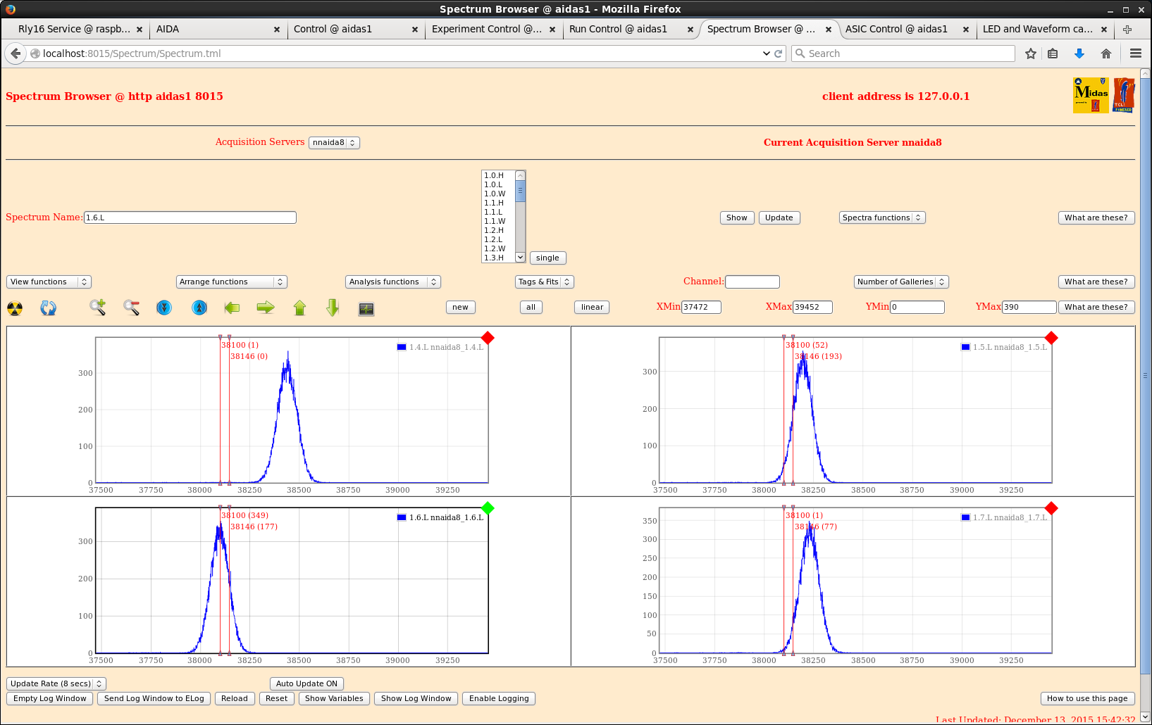
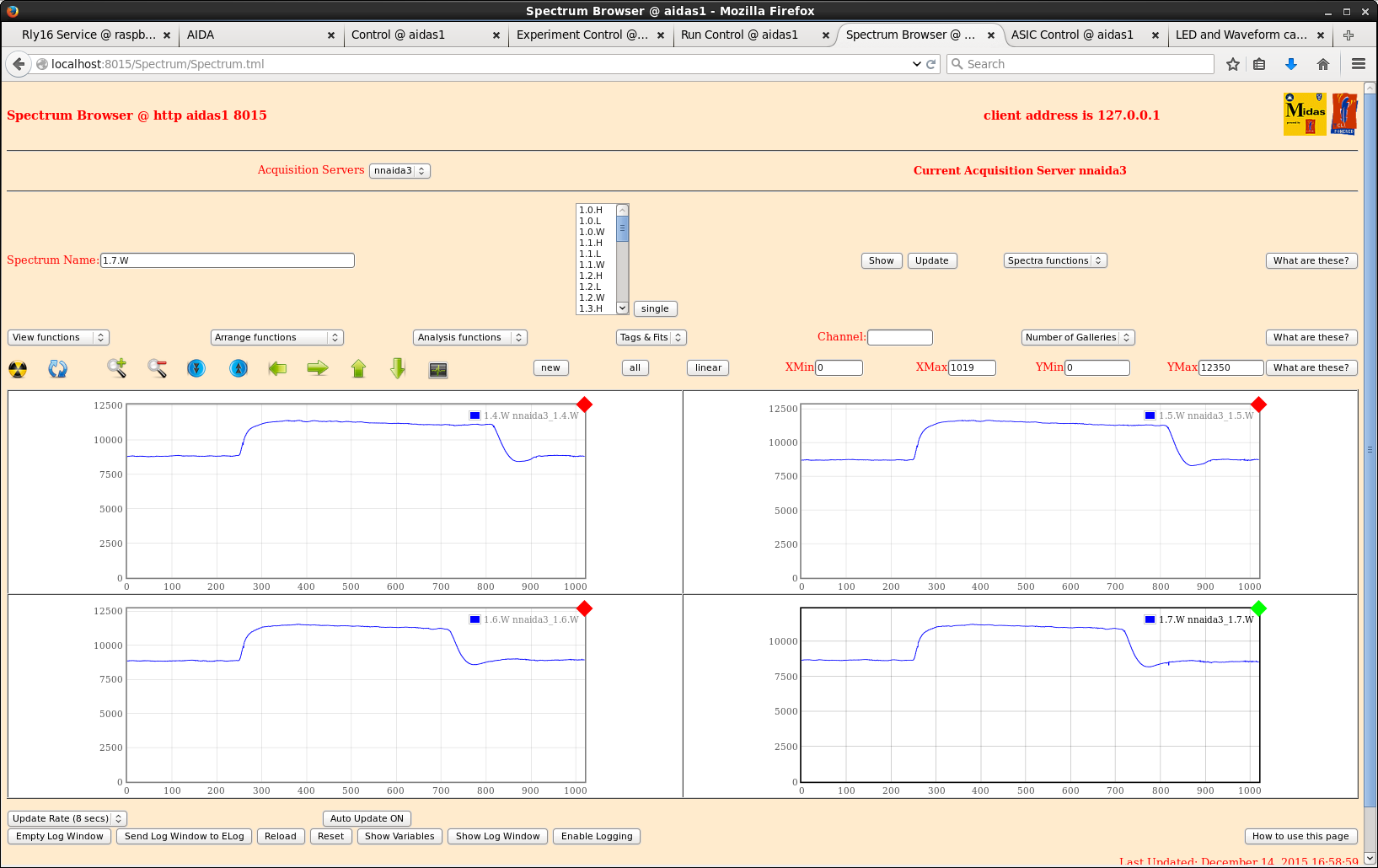
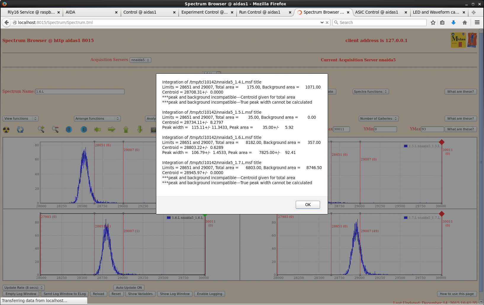
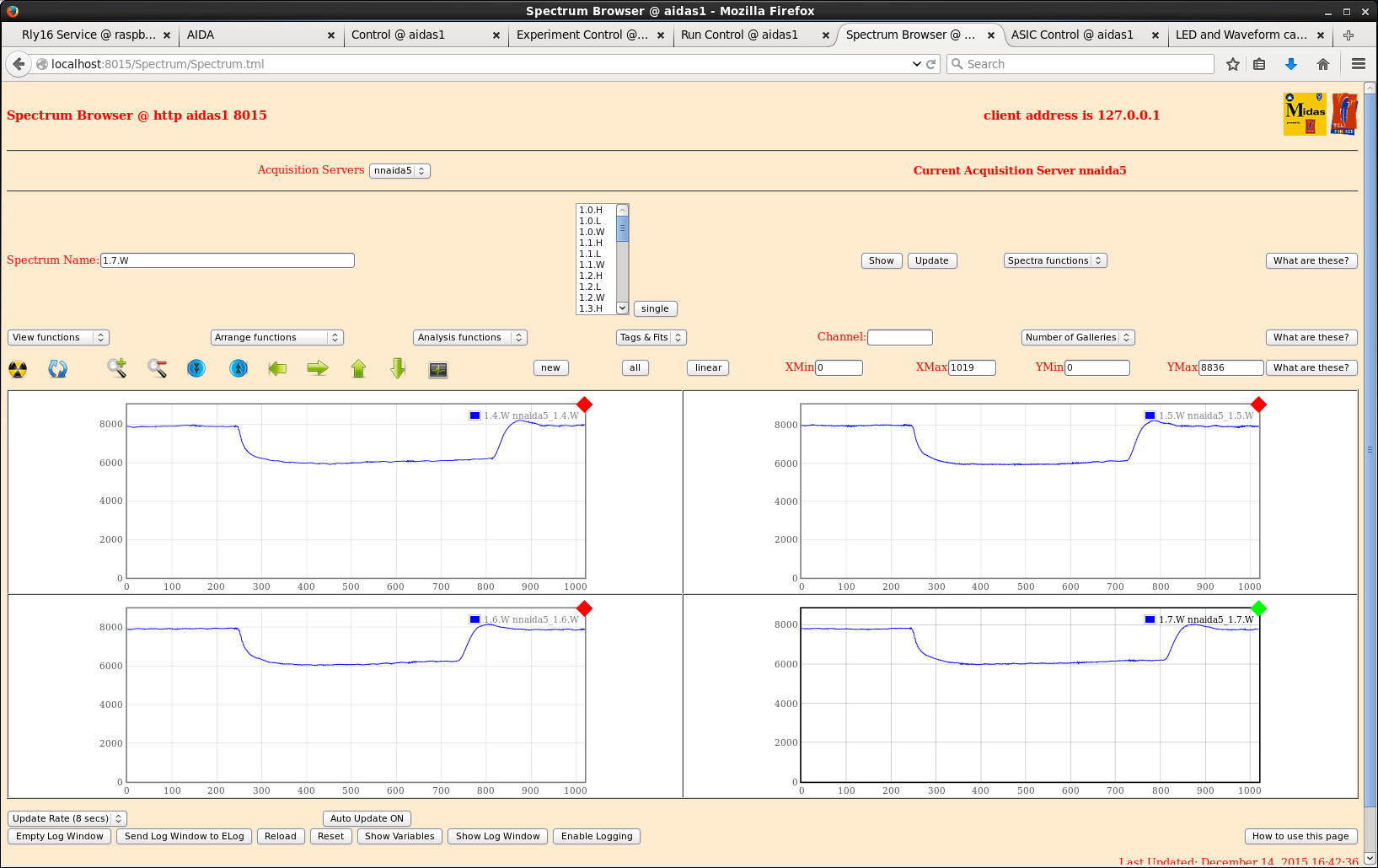
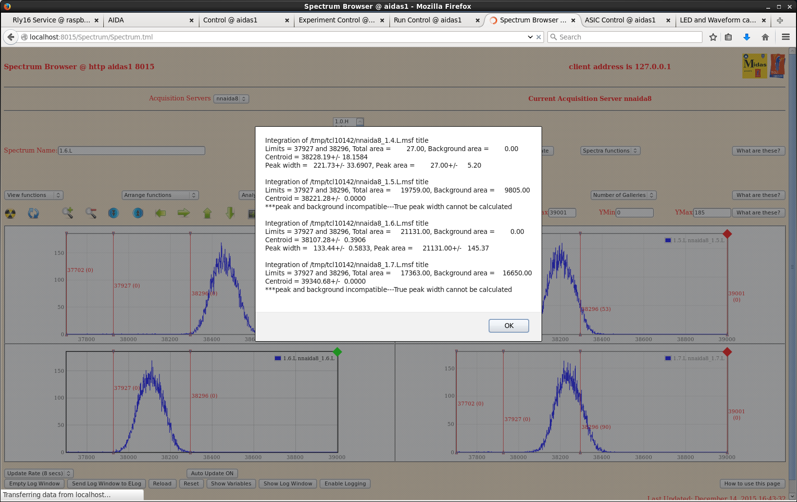
Powered system up as it was last night -> 2977-15 connected to nnaida1,3,5,8 with only 4 FEE modules powered.
- n-side widths ~190-200 ch
- p-side widths ~100ch
- jumpers as above, ASIC setting as 2015Dec12_smallSetup, wav thresholds all at 500 apart from nnaida5 @ 250.
Spend remainder of day trying to fit mezzanine cables.
14/12/15
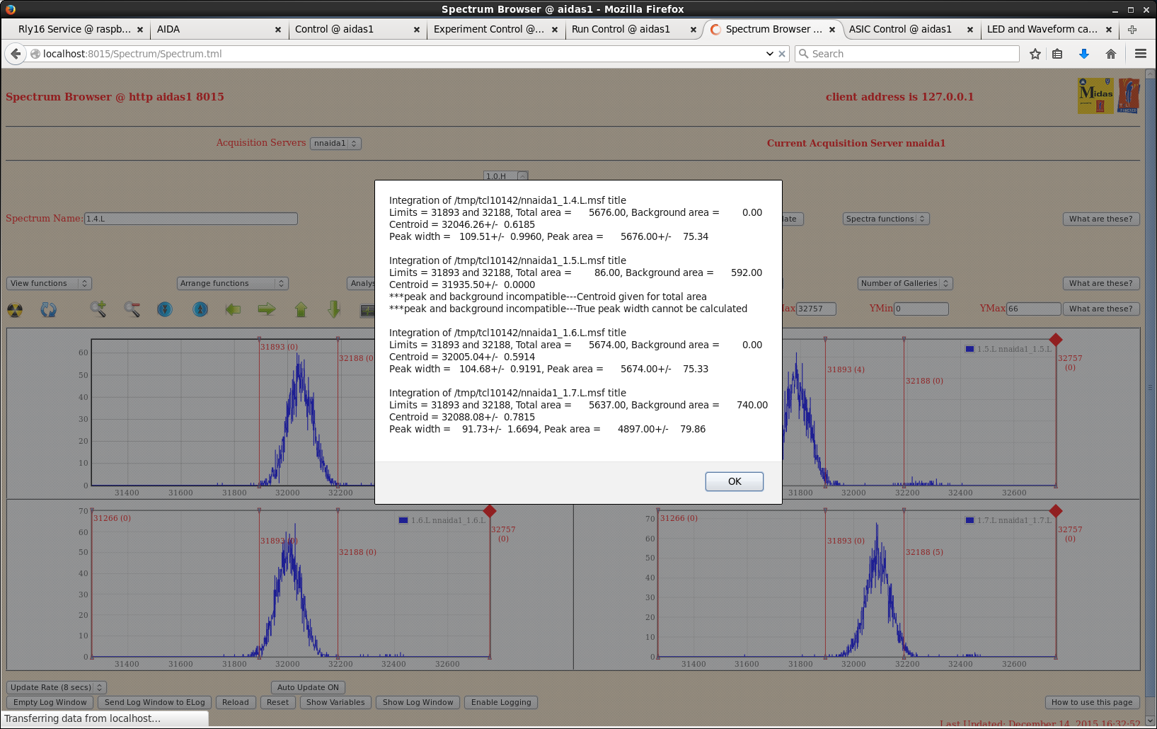
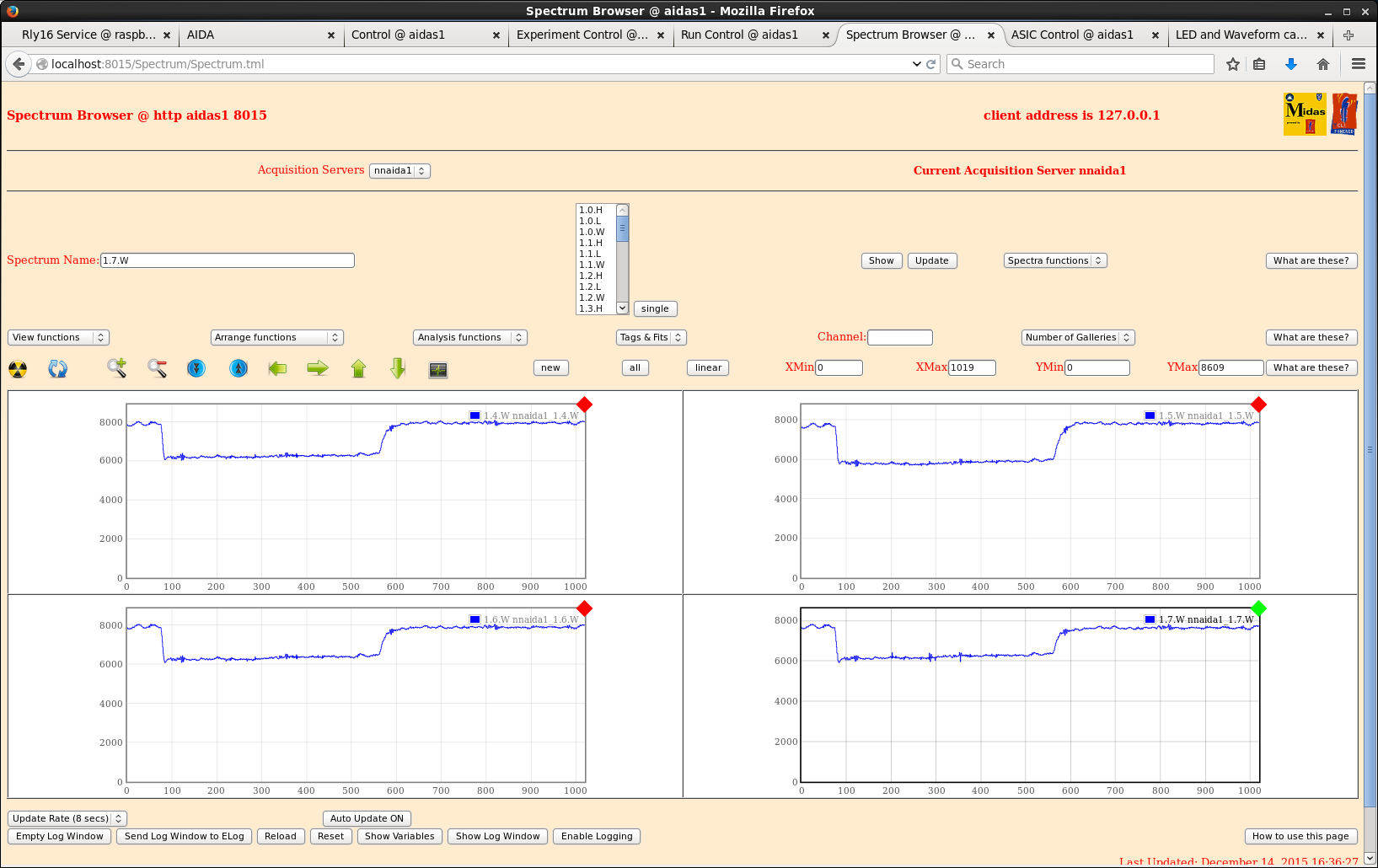
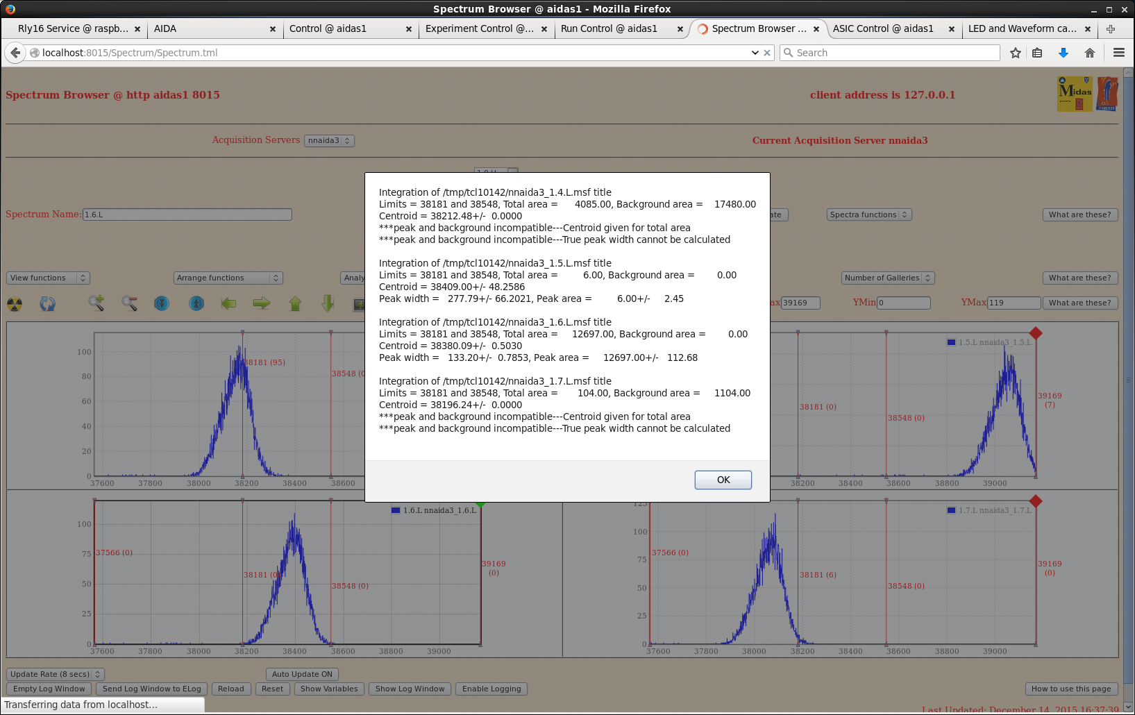
Completed installation of mezzanine cables.
Resistance between all mezzanines and cooling crates still ~200 kOhms (up from ~2-5 Ohms on our arrival), apart from nnaida7+8, which is now at ~5 Ohms
However, all see resistance to main vertical copper pipe of ~3 Ohms.
As best as I can see, isolating tape in still in place for all FEEs => unknown point of contact.
> LEMO cables to test inputs carry ground connection from NIM bin -> NIM bin in electrical contact with support frame -> coolant loop in electrical contact with support frame => electrical connection still present between FEEs and coolant loop, even in insulating guide pins are introduced
> this problem is not observed at DL because the NIM bin in on the wooden table top and isolated from the coolant loop and any support structure
> is it possible to isolate the NIM bins from the support structure?
> need to come up with some more systematic and fixed way/positions for measuring these resistances, i.e. always measure mezzanine to X.
Resistance between all mezzanines now ~ 0.5 Ohms.
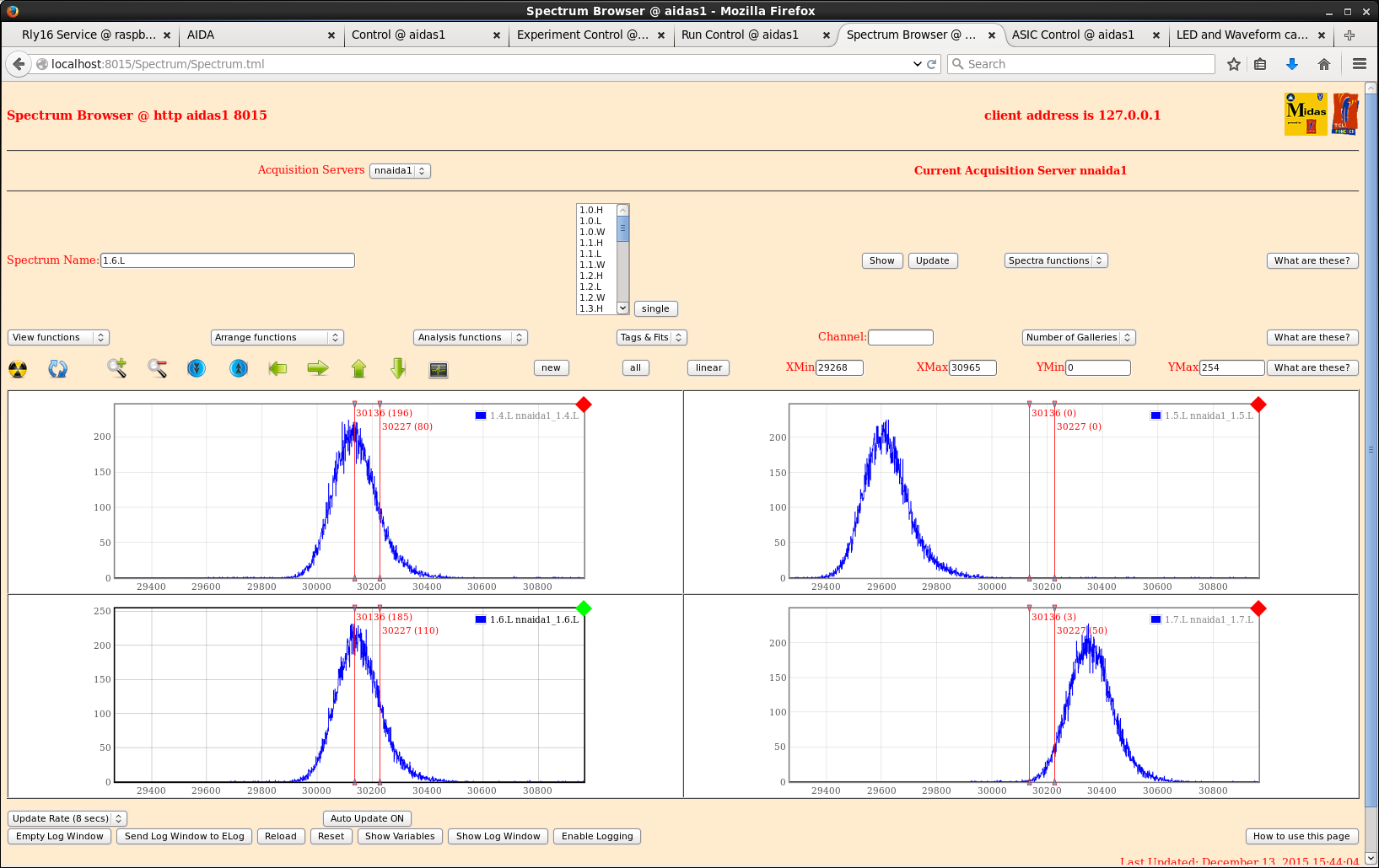
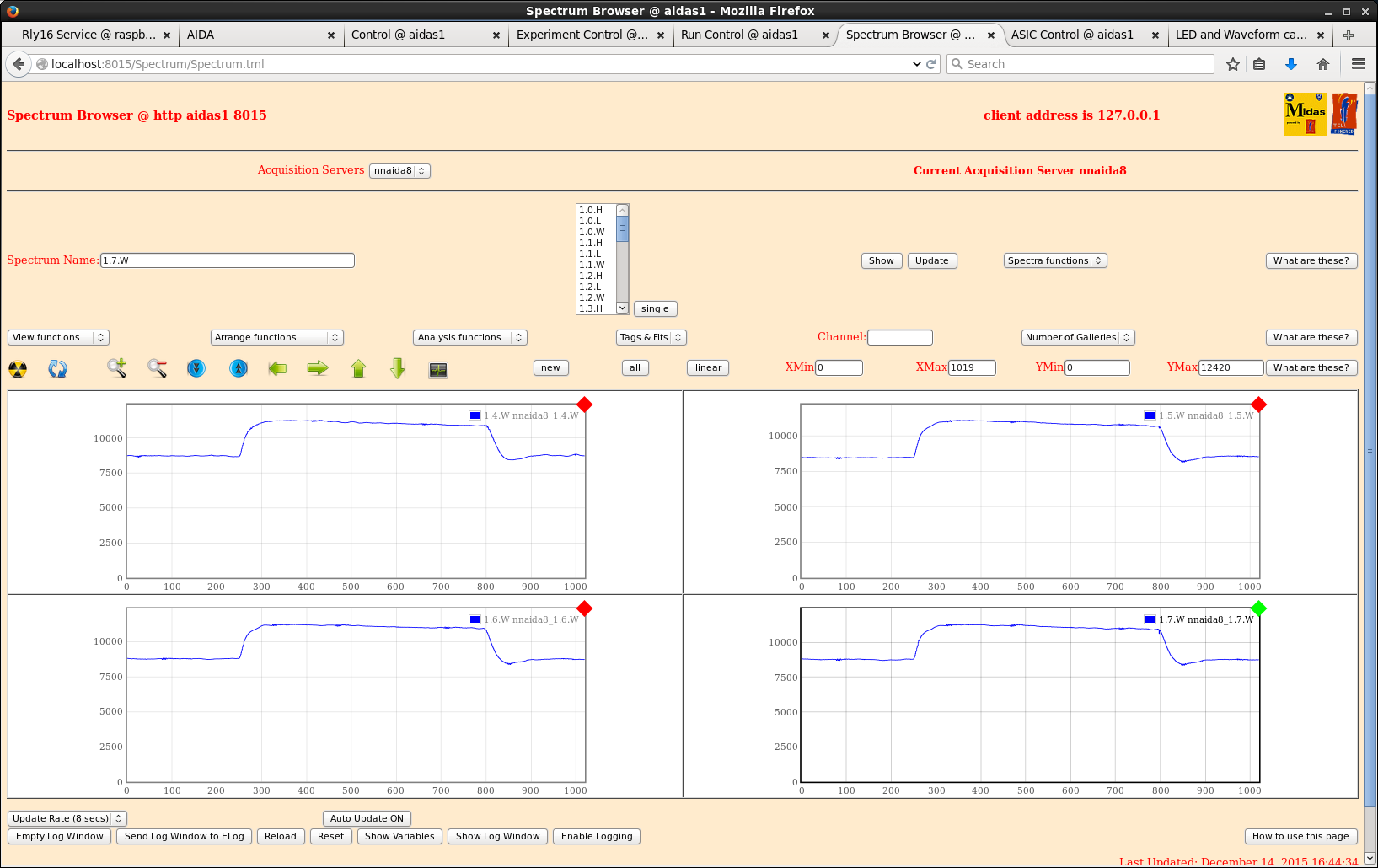
n-side widths ~ 120ch and p-side widths ~ 120ch => peak widths almost halved in n-side, but increased by ~20% in p-side.
Attempted to bias previously tripped detector.
- same jumper combination as other detector caused failure to bias > leakage current jumps to 50uA at ~2V and trips shortly after, ramping back down from there.
- removed all jumpers and see same thing.
Will try again in the morning by attaching 3131-11 to cables currently on 2977-15, but it looks like 3131-11 really is defective somehow. |
| Attachment 1: nnaida1_spec.png
|
|
| Attachment 2: nnaida8_spec.png
|
|
| Attachment 3: nnaida1_spec_mezzCablesOn.png
|
|
| Attachment 4: nnaida1_wav_mezzCablesOn.png
|
|
| Attachment 5: nnaida3_spec_mezzCablesOn.png
|
|
| Attachment 6: nnaida3_wav_mezzCablesOn.png
|
|
| Attachment 7: nnaida5_spec_mezzCablesOn.png
|
|
| Attachment 8: nnaida5_wav_mezzCablesOn.png
|
|
| Attachment 9: nnaida8_spec_mezzCablesOn.png
|
|
| Attachment 10: nnaida8_wav_mezzCablesOn.png
|
|
|
|
133
|
Sat Dec 12 03:30:50 2015 |
Alfred, Chris, Phong | change configuration of NNAIDA modules in setup |
We want to reduce the configuration of the setup to 4 FEE cards (8 NNAIDA modules), so we only have to isolate 4 of them from the cooling crate for a noise test. Following instructions in April2015 test logbook.
Copied directory /MIDAS@aidas to /MIDAS@aidas.121215
In /MIDAS@aidas/config/TclHttpd/aidas1@8015 edit file:
-rw-rw-r--. 1 npg npgstaff 2281 May 3 2015 startup.tcl
Now scripts does 'lappend ACQSERVERS nnaida$i' from i=1 to 8
|
|
|
132
|
Sat Dec 12 02:12:17 2015 |
CG, AE, VH | RIKEN progress |
Stripped down contents of AIDA NIM bins to only what is required by AIDA.
Now have BNC PB-5 pulser, sum and invert module, single and quad Caen HV supplies in the top crate and the MACBs in the bottom crate.
Removed were FIFO, leading edge discriminator and a quad coincidence module, all used in the DAQ integration.
Smallest dial on pulser potentiometer was round at an unlikely number, seems to have been knocked.
- connected to scope and consecutive values on the biggest dial does not produce integer multiples of the lowest setting -> needs sorting out for future pulser walkthroughs.
Tested tripped detector from Apr/May (BB18-1000 3131-11) with kaptons connected to nnaida1,3,5,8 (GND to nnaida1), +ve HV with braid to front strips via nnaida5 and core to back strips via nnaida3.
- biased to +150V with a stable leakage current of 9.5uA in a very warm room.
- stable for ~2mins then I_L jumped to 20uA and detector tripped.
- subsequently unable to successfully bias the detector. Trips on ramping up around 15-20V every time.
- no visible damage or broken bond wire.
Initial conclusion is this detector is broken (but see bellow). Then tried with another (BB18-1000 2977-15, pre-prod)
- encountered similar problems in that the detector tripped once at ~+50V and then kept tripping around +12V thereafter.
This was all carried out with the jumper combination already present from the end of the run in May - Lk1,3,5+7 had jumpers on on all FEEs, but we were unable to bias detector.
Removed all jumpers and 2977-15 biased successfully to ~75V (with 10.12 uA leakage current). Pulser resolution ~700 ch FWHM for NNAIDA 1 (p-side); 20 ch for NNAIDA2 (no DSSD connected)
Setting1:
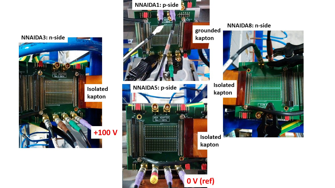
- Add jumpers LK1 to nnaida1 (w/grounded Kapton cable), LK3 to nnaida3 (+75 V), LK1 and LK3 to nnaida5 (ref. 0V), and LK3 to nnaida8 (revB PCB). See attachment 1.
- Biased with 10.44 uA leakage current @ 75V
- About half of the Cu-braids with ground connections across FEEs are loose (clamps had snapped while moving table/mounting DSSD).
- Using 2015Apr30-diode-mod2 ASIC settings.
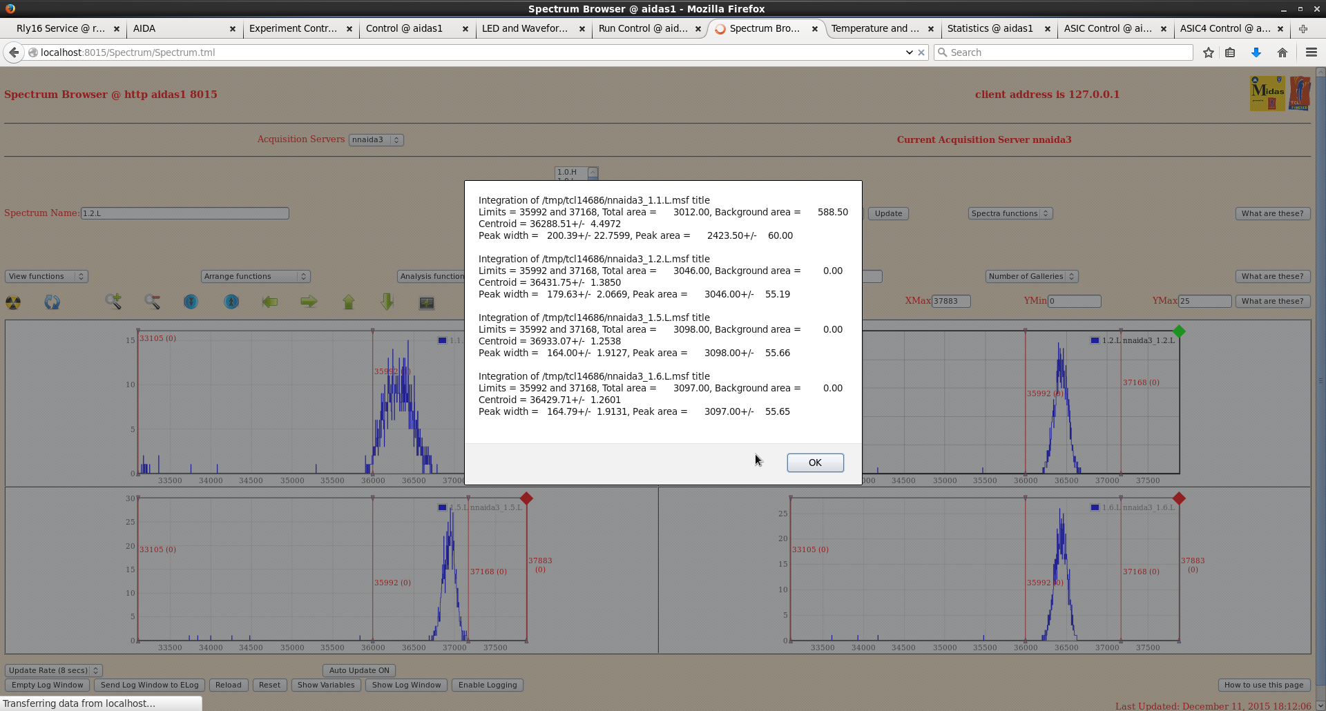
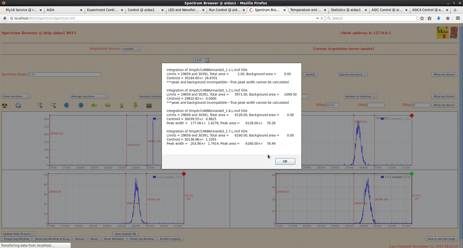
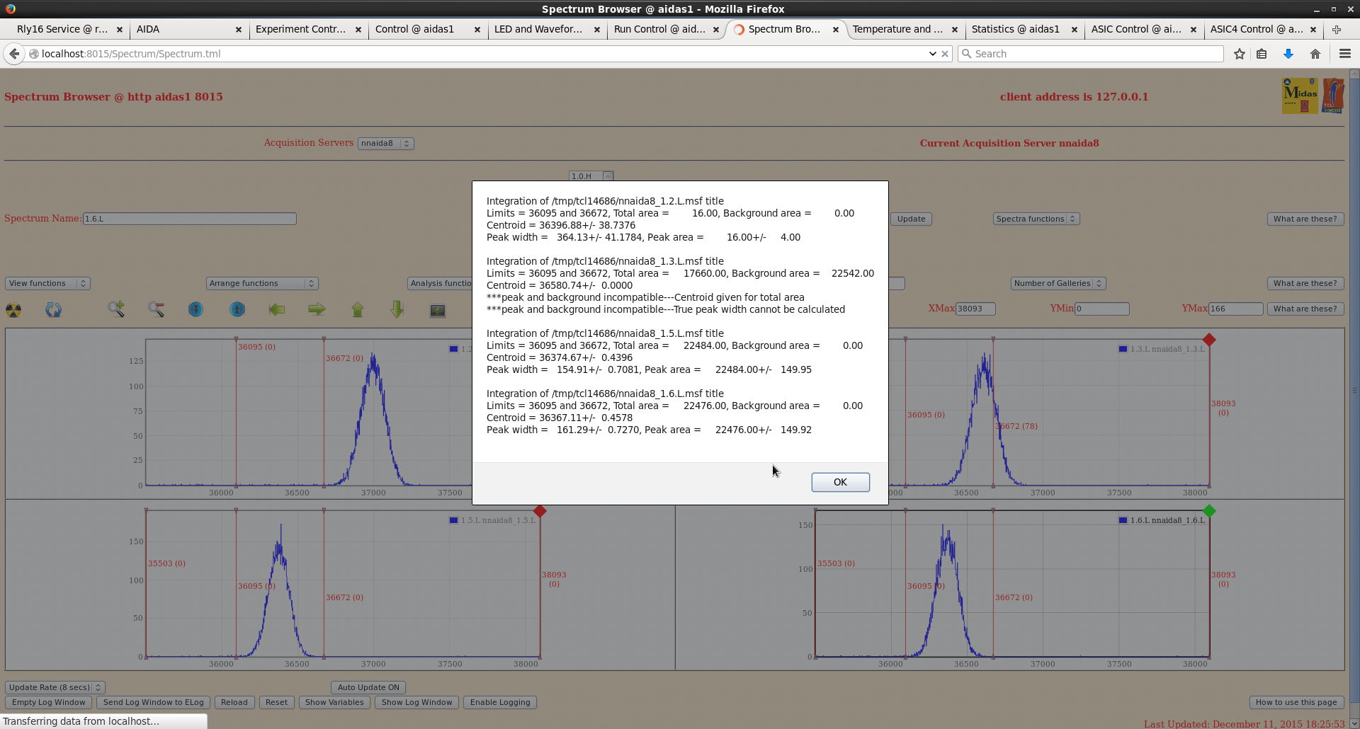
- Resolution of sample channels (FWHM): nnaida1: 320 ch, nnaida3: 500 ch, nnaida5: 280 ch, nnaida8: 180 ch.
Tried a couple more jumper settings:
- nnaida1: LK1+LK3, nnaida3: LK3, nnaida5: LK1+LK3, nnaida8: LK1+LK3: overcurrent with a couple of volts (short circuit, likely LK1 in nnaida8).
- nnaida1: LK1+LK3, nnaida3: LK3, nnaida5: LK1+LK3, nnaida8: LK3: detector trips (I>20uA) at about 18 V, and after tripping first time there is a steeper increase of I vs V (~20uA at ~ 9V).
Setting2:
- Same jumpers as setting 1: nnaida1: LK1, nnaida3: LK3, nnaida5: LK1+LK3, nnaida8: LK3.
- Connect all Cu-braid cables to ground the Cu blocks of first two rings of FEEs.
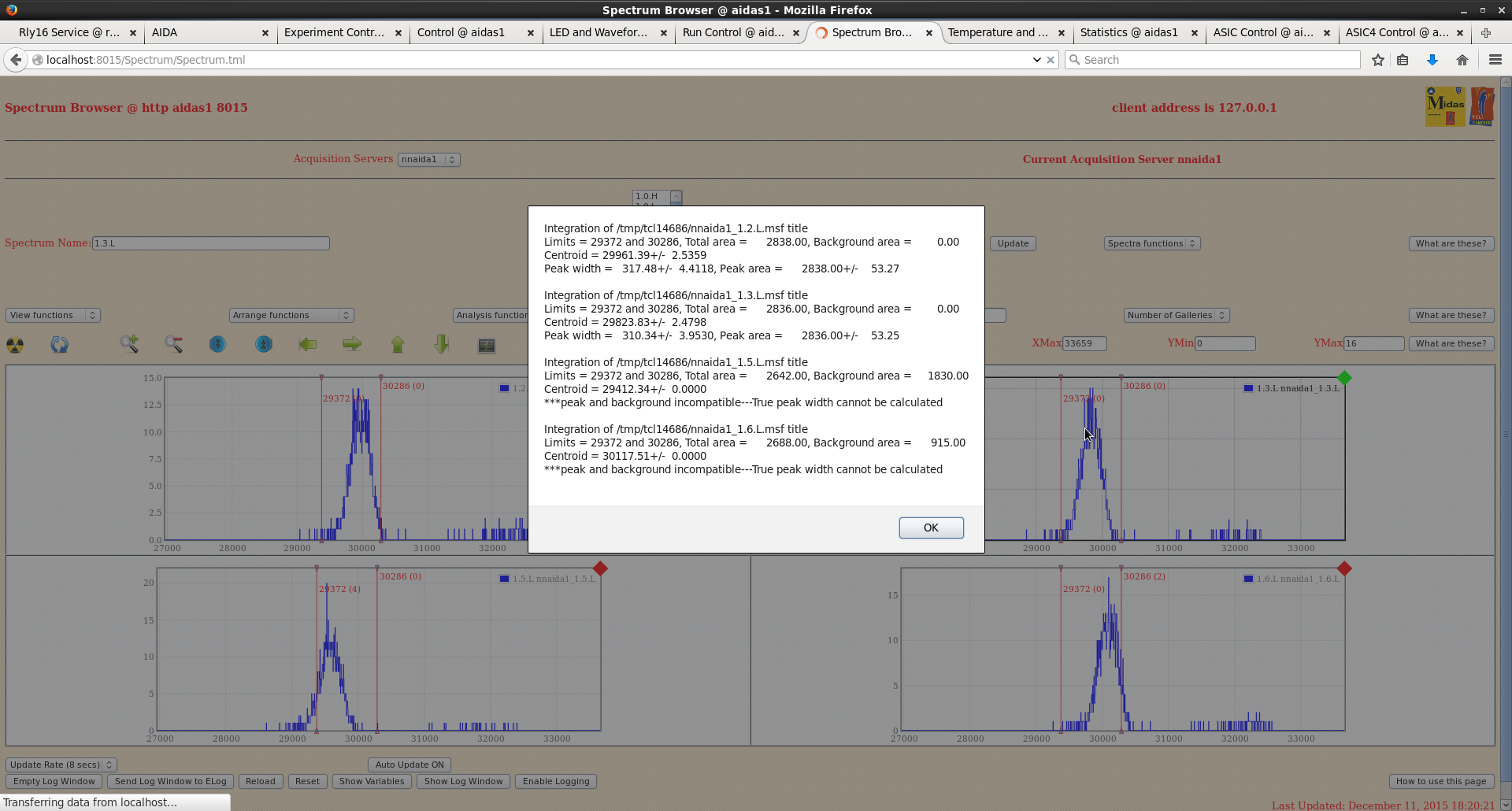
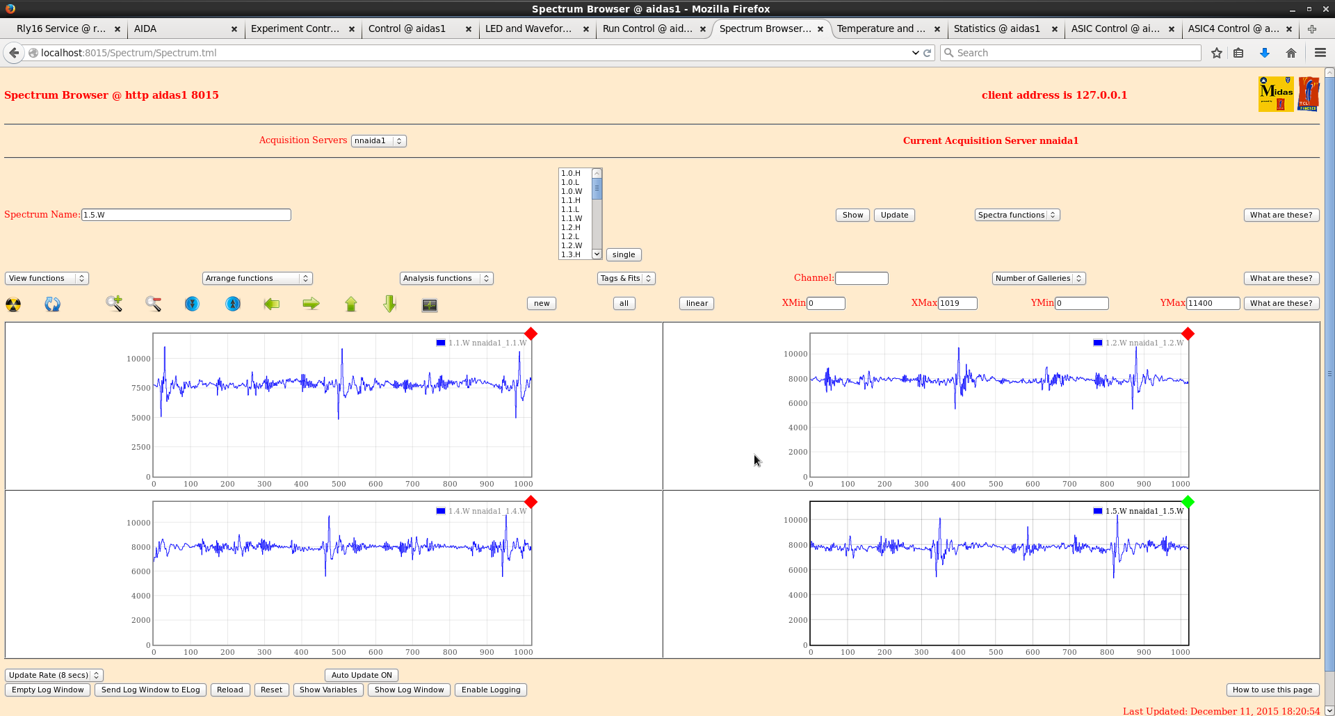
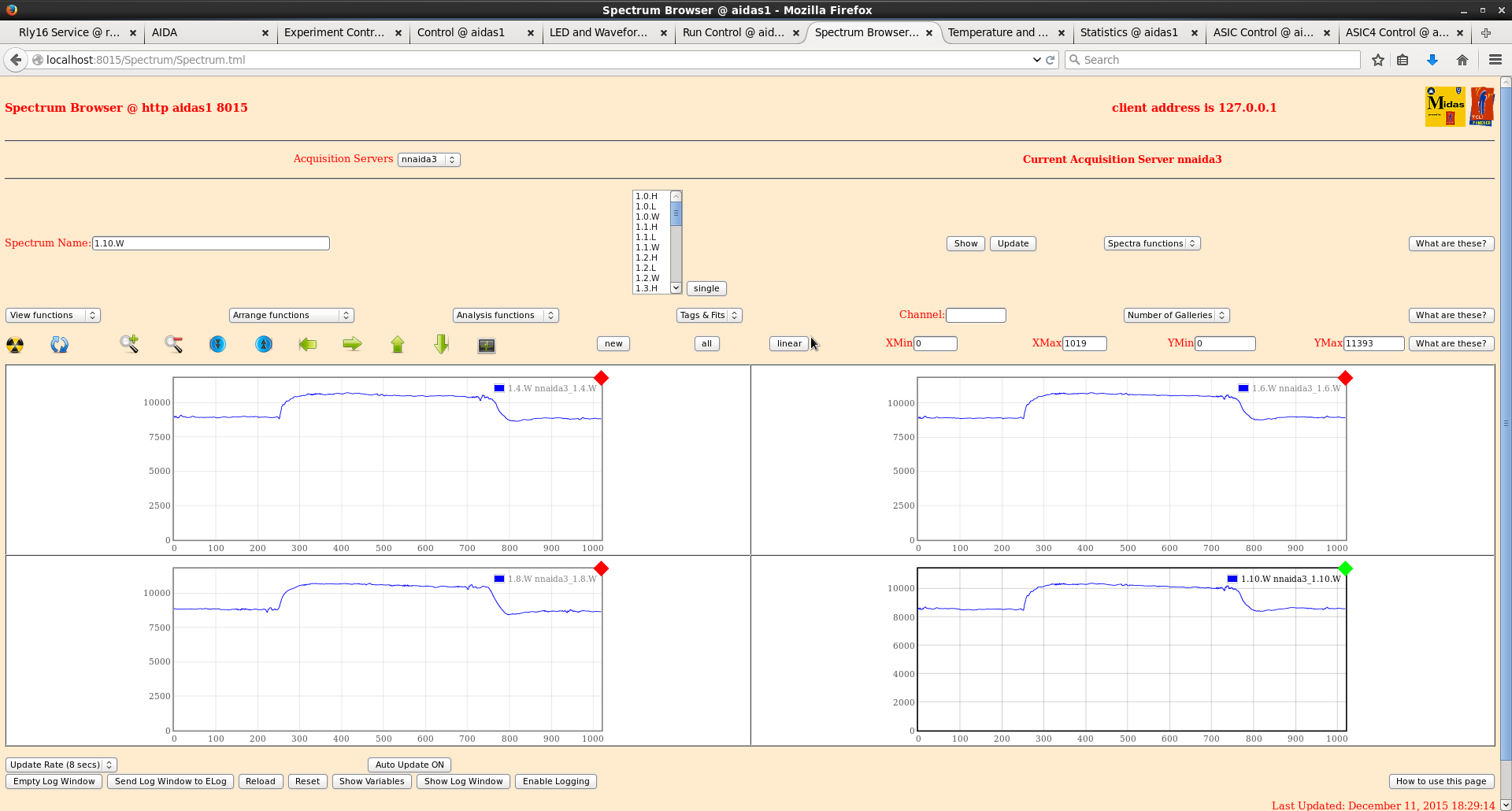
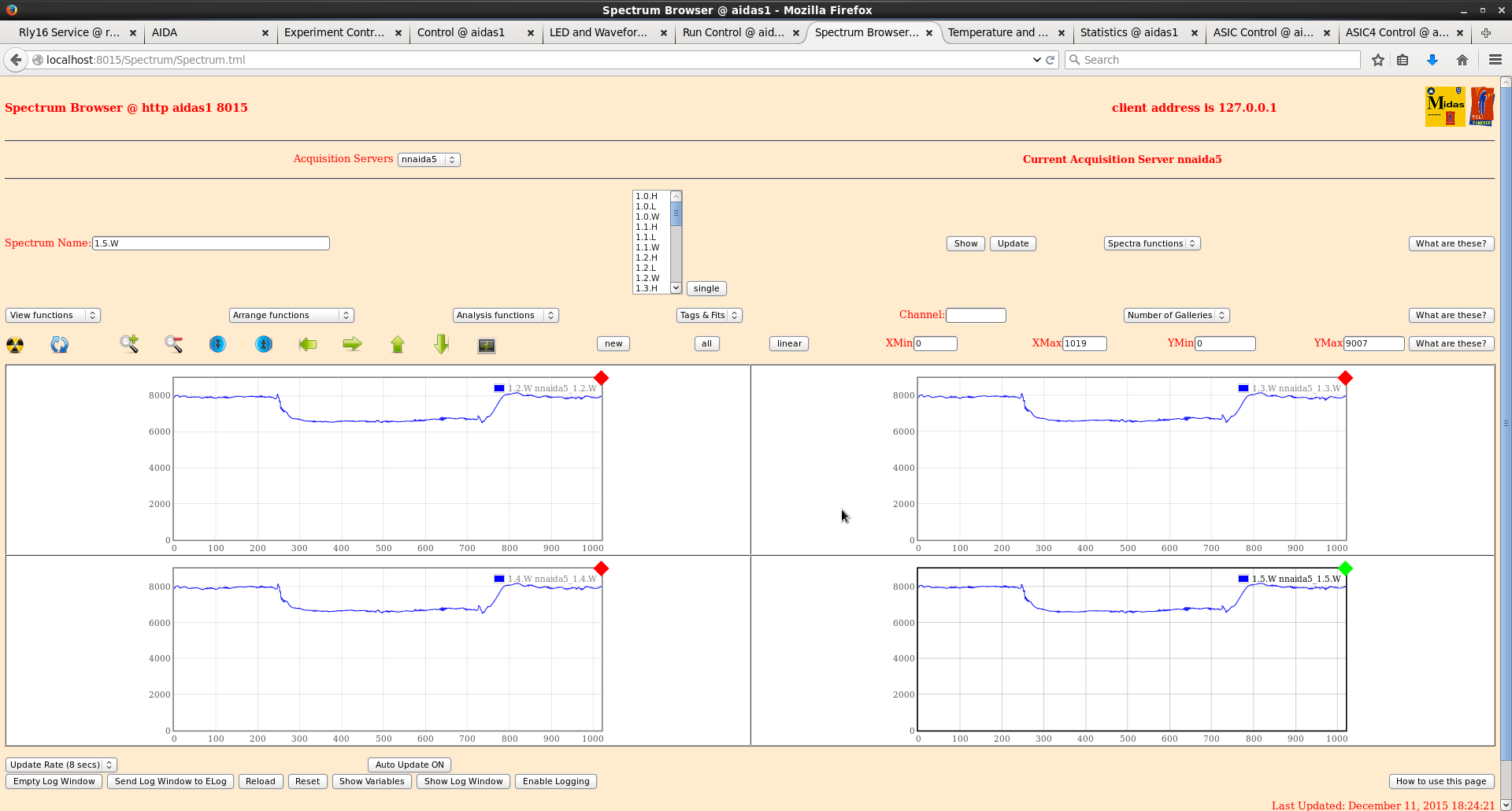
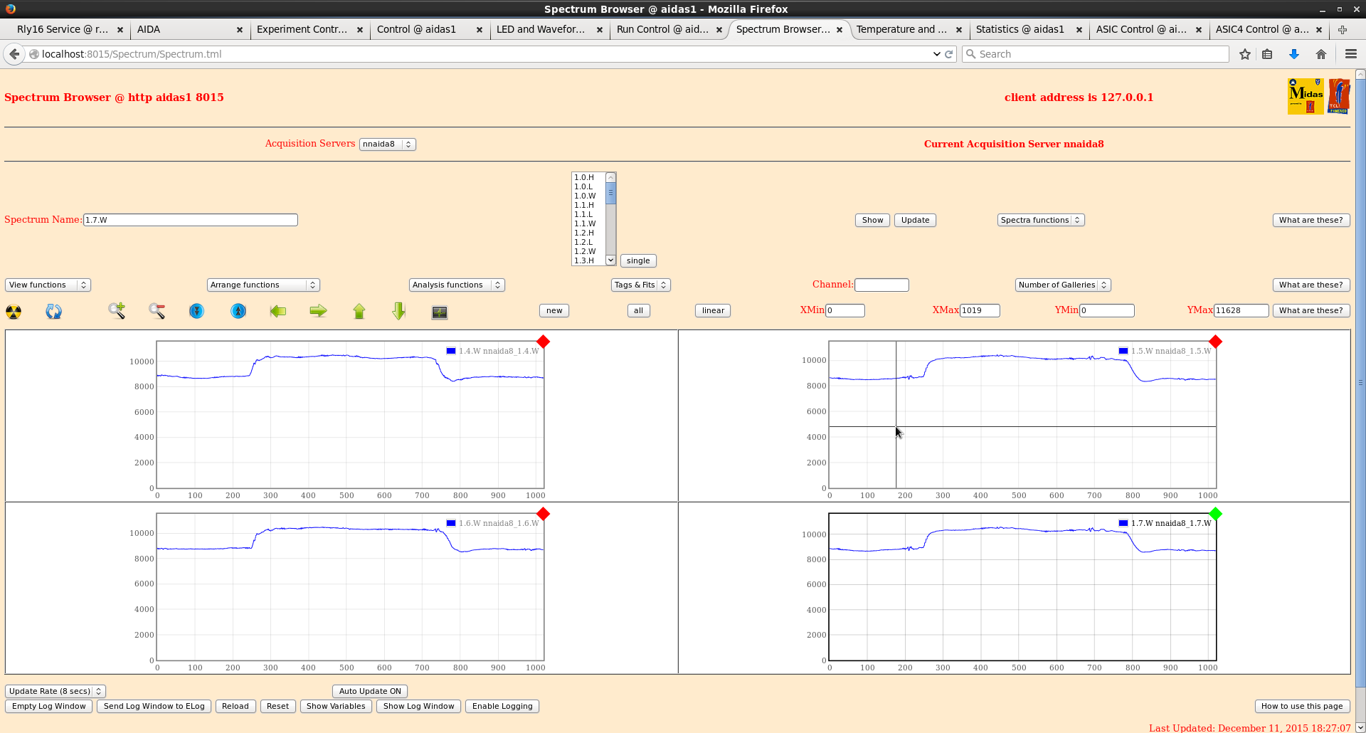
- The resolution in all FEEs improved to about 170ch FWHM, except for nnaida1 (with grounded Kapton cable): nnaida1: 310 ch, nnaida3: 170 ch, nnaida5: 180 ch, nnaida8: 160 ch. See attached sample spectra and waveforms.
|
| Attachment 1: Dec2015_jumpers.jpg
|
|
| Attachment 2: DSSD_set2_nnaida1_L.png
|
|
| Attachment 3: DSSD_set2_nnaida1_wf.png
|
|
| Attachment 4: DSSD_set2_nnaida3_L.png
|
|
| Attachment 5: DSSD_set2_nnaida3_wf.png
|
|
| Attachment 6: DSSD_set2_nnaida5_L.png
|
|
| Attachment 7: DSSD_set2_nnaida5_wf.png
|
|
| Attachment 8: DSSD_set2_nnaida8_L.png
|
|
| Attachment 9: DSSD_set2_nnaida8_wf.png
|
|
|
|
131
|
Thu Dec 10 04:56:08 2015 |
CG, AE | RIKEN progress - first day and a half |
08/12/15 - Day 0.5
Test fitted new snout to snout base
- the holes in the base of the just-shipped section all line up with those in the corresponding part just taken off.
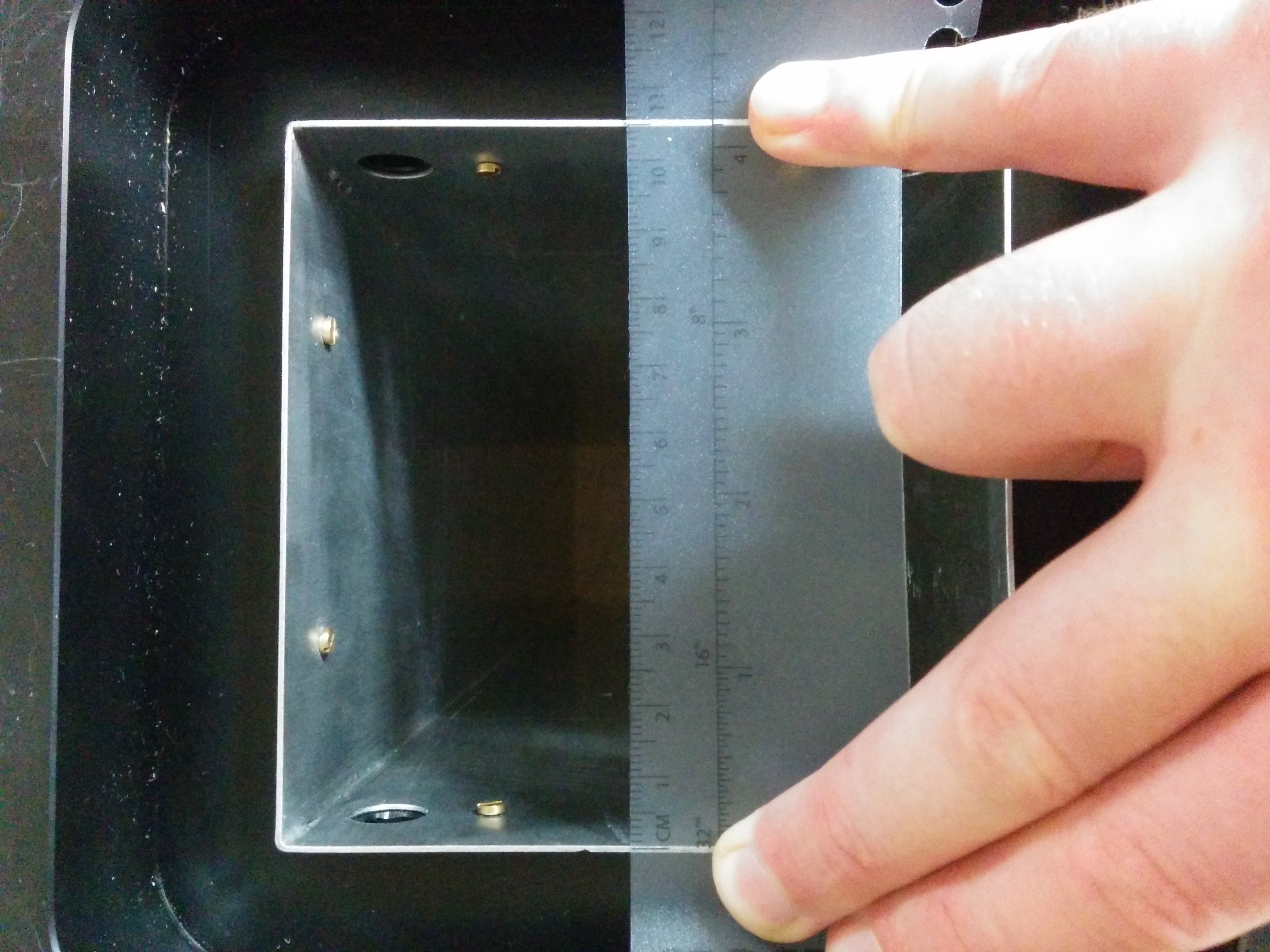
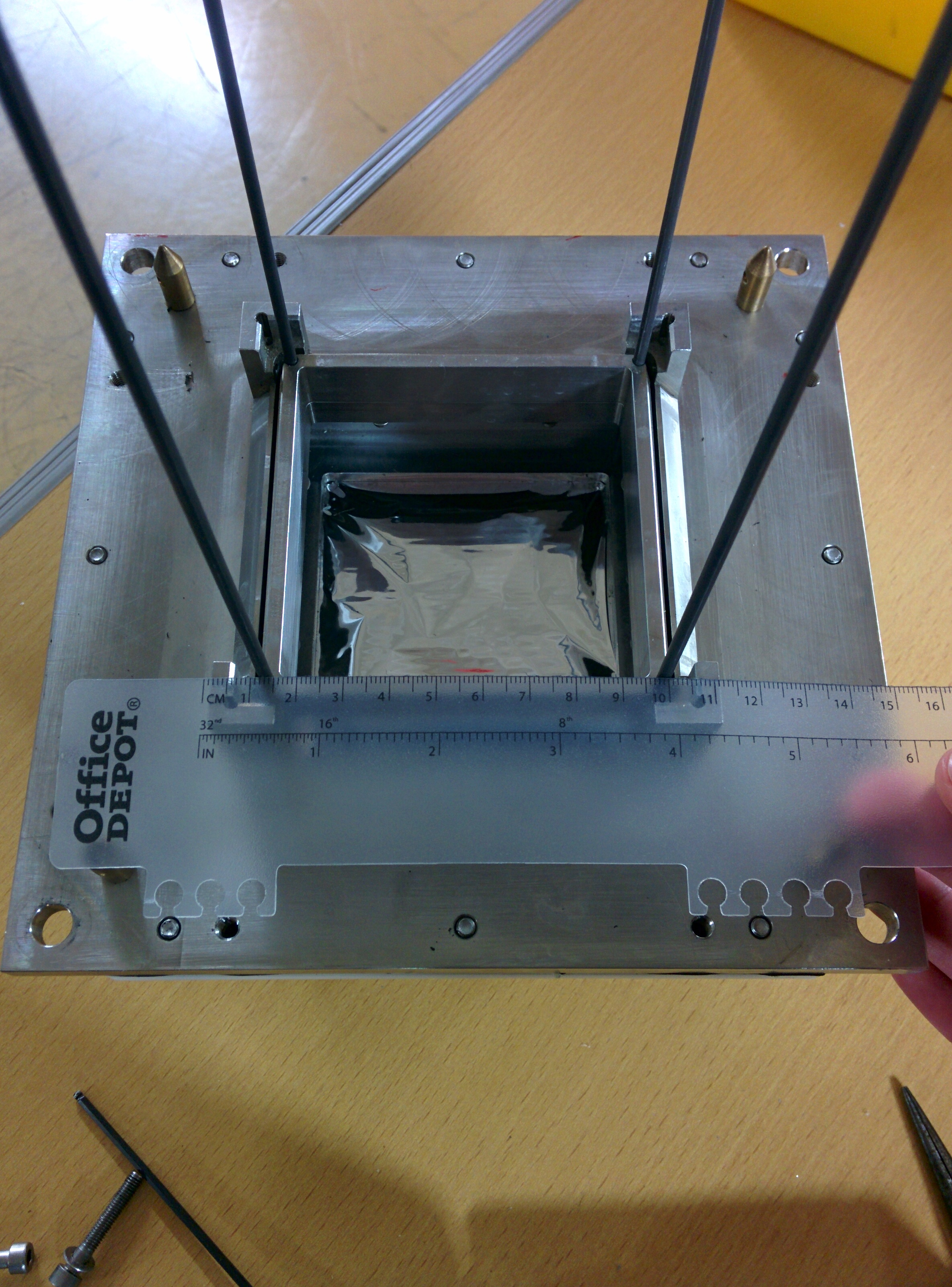
- however, the raised corners of the rear metal plate (around the rods), which sits in the downstream end of the Al section of the snout now presents a conflict.
- the old snout sat inside the raised section but, now that the side length of the snout has been increased, there is a conflict between the snout and the raised portion (see attached photos), which means the snout will not seat properly in the base section.
Checked for electrical connection between cooling crate and FEE mezzanines
- connection present in all FEEs with resistance < 2 Ohms for most, and the maximum at 1 kOhm for one of the FEE modules.
09/12/15
Moved AIDA back into rough experimental position, re-cabled setup and powered on complete system.
Chiller levels ok, no leaks after ~1hr of operation. Temperatures all remained low and stable.
|
| Attachment 1: 2015-12-08_16.19.16.jpg
|
|
| Attachment 2: 2015-12-08_16.16.30.jpg
|
|
|
|
130
|
Thu Dec 3 16:28:46 2015 |
CG, TD | New Kapton cable tests at DL |
Spent whole day trying to isolate mezzanines from cooling crate.
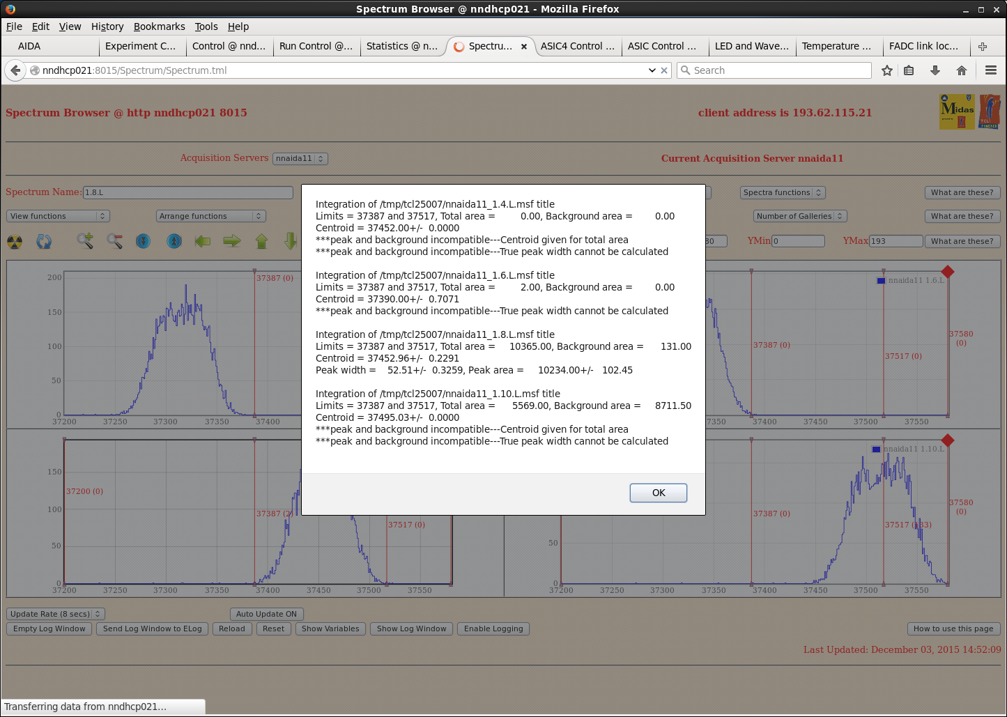
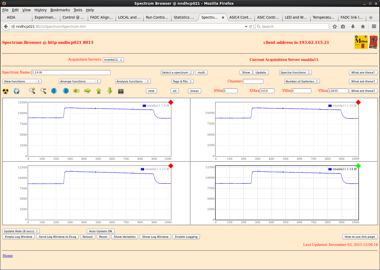
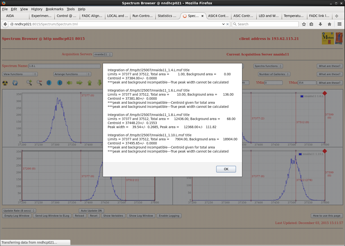
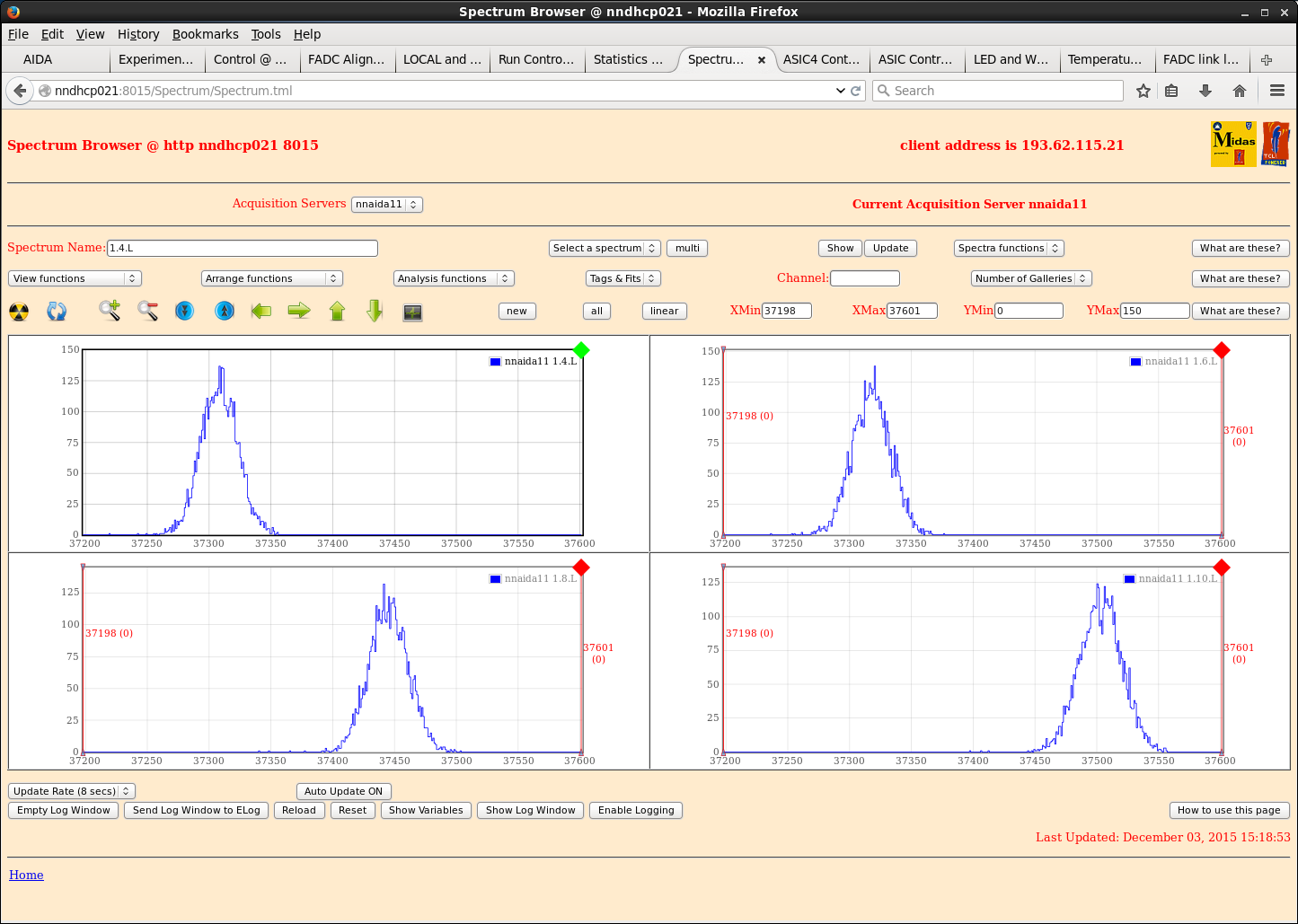
Finally managed to increase resistance between crate and mezzanines from ~5 Ohms to ~380 kOhms with some masking tape and parcel tape over the slots in the FEE modules in which rest the guide pins on the bottom of cooling crate.
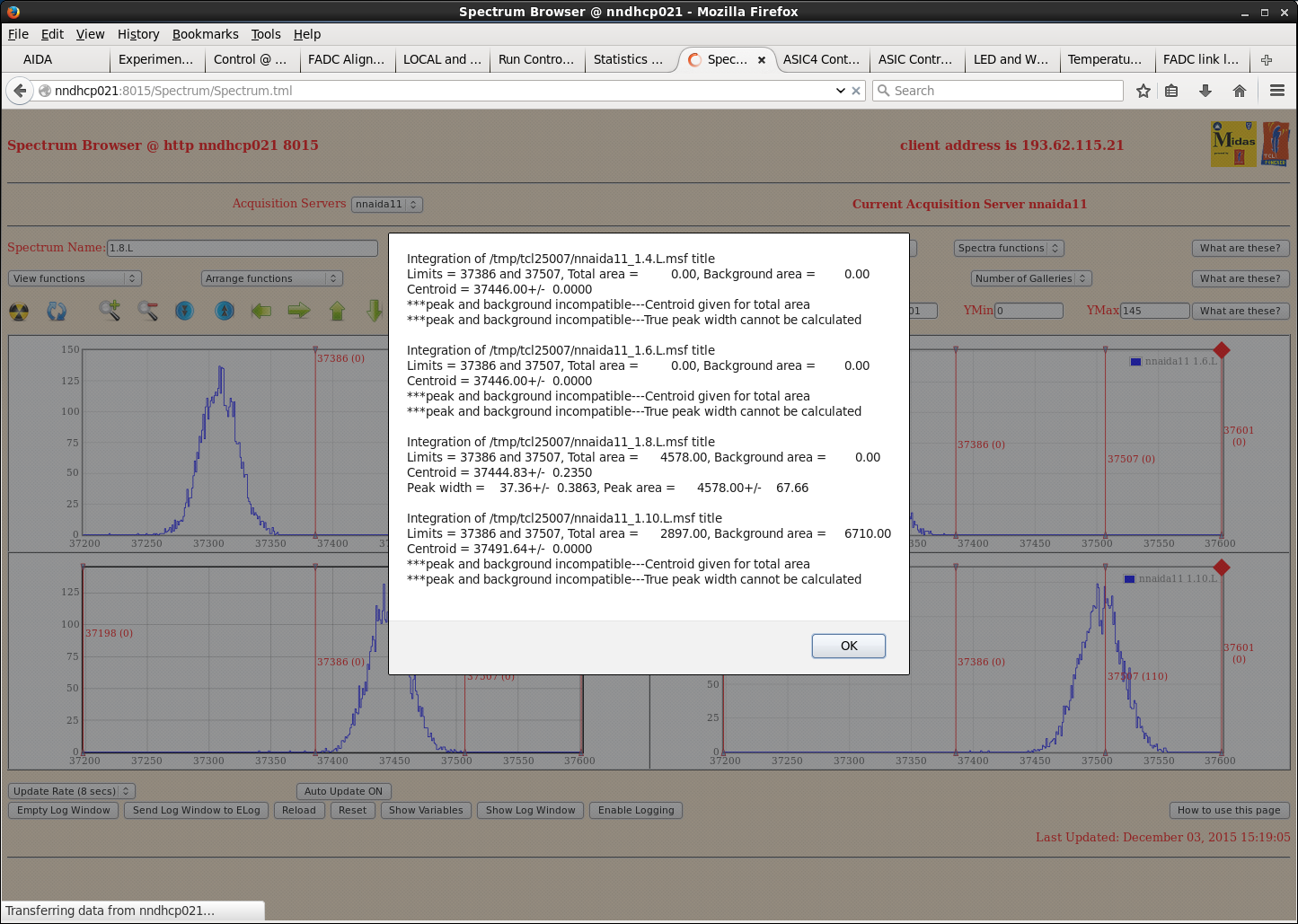
See excellent performance in nnaida11, with peak widths down to ~45ch and almost perfectly smooth waveforms.
- this is with just the kaptons connected (all of which are shielded with tape) and no detector. Shaping time of 8us.
Performance in other FEEs remains largely unchanged. (Note: Yesterday saw similar performance in nnaida13+14 for 15mins but lost it and couldn't regain same performance.)
Turned off cooler to see what effect that had - no major changes to peak widths.
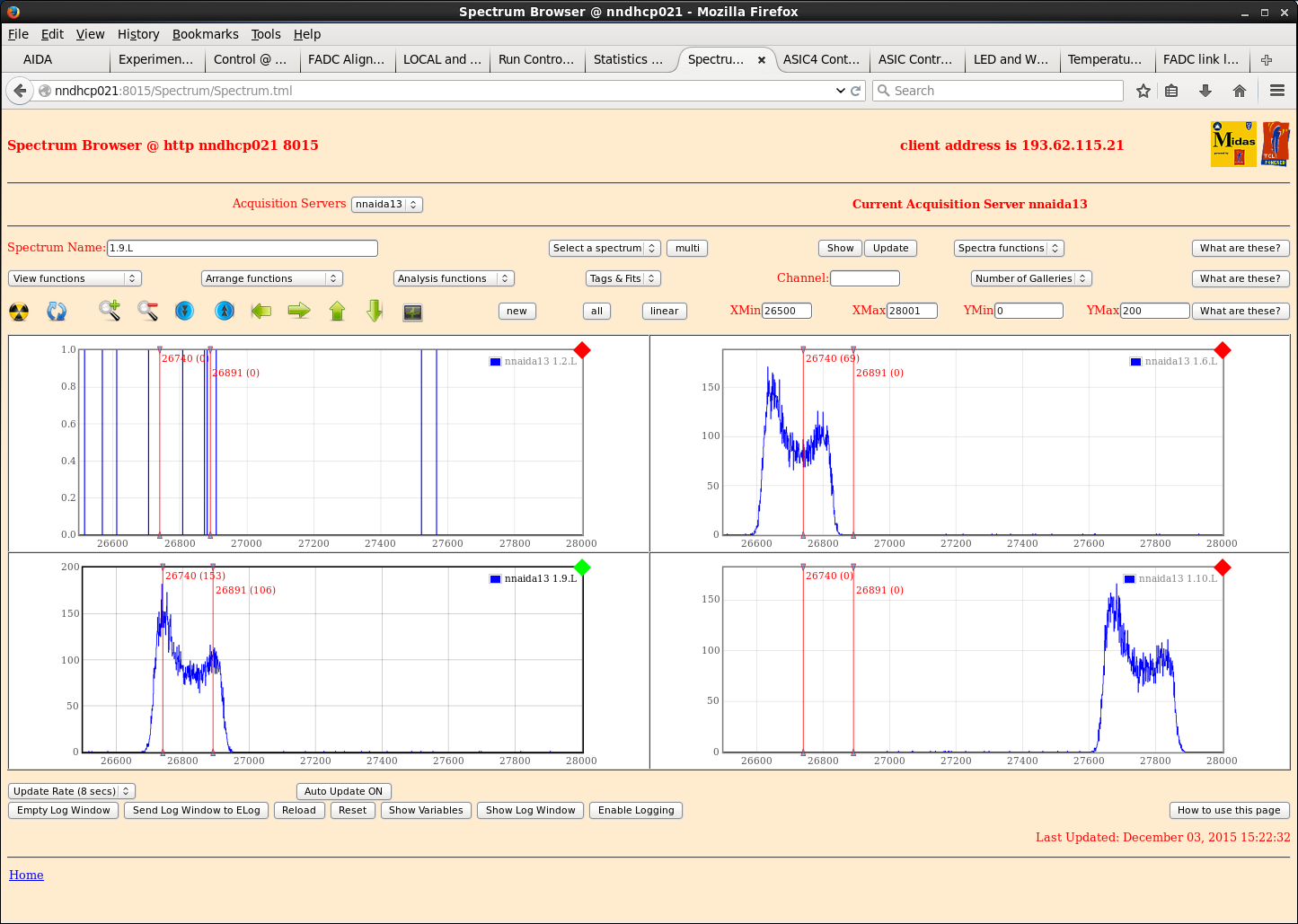
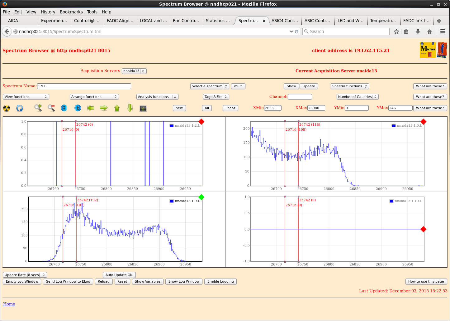
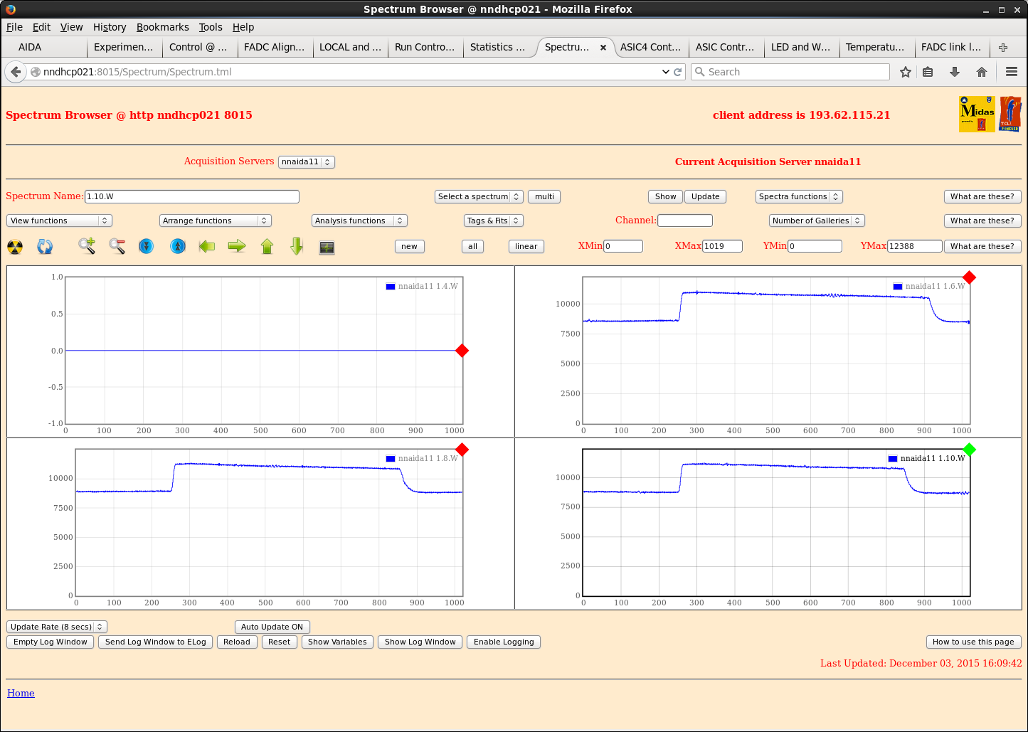
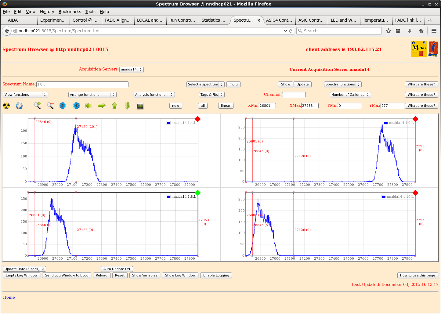
Turned off cooler and loosened crate lid - again no appreciable difference.
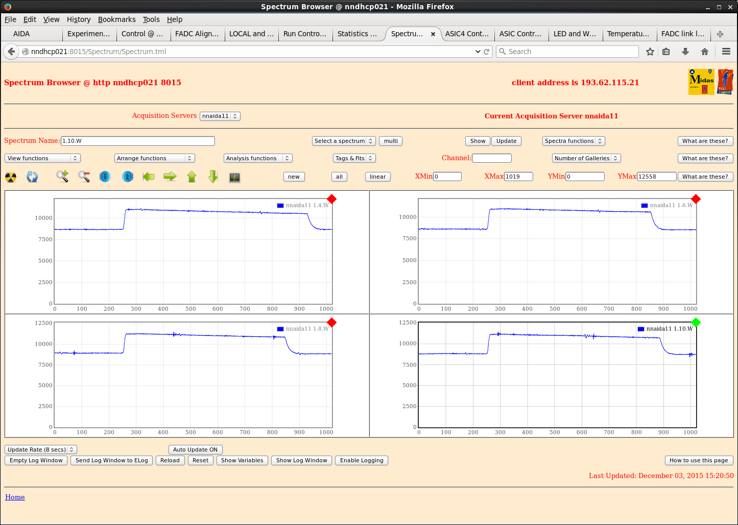
=> It seems this electrical connection between cooling crate and mezzanines could be the source of a lot of our noise.
Could remove pins completely to see effect that has, before trying with plastic ones when they arrive.
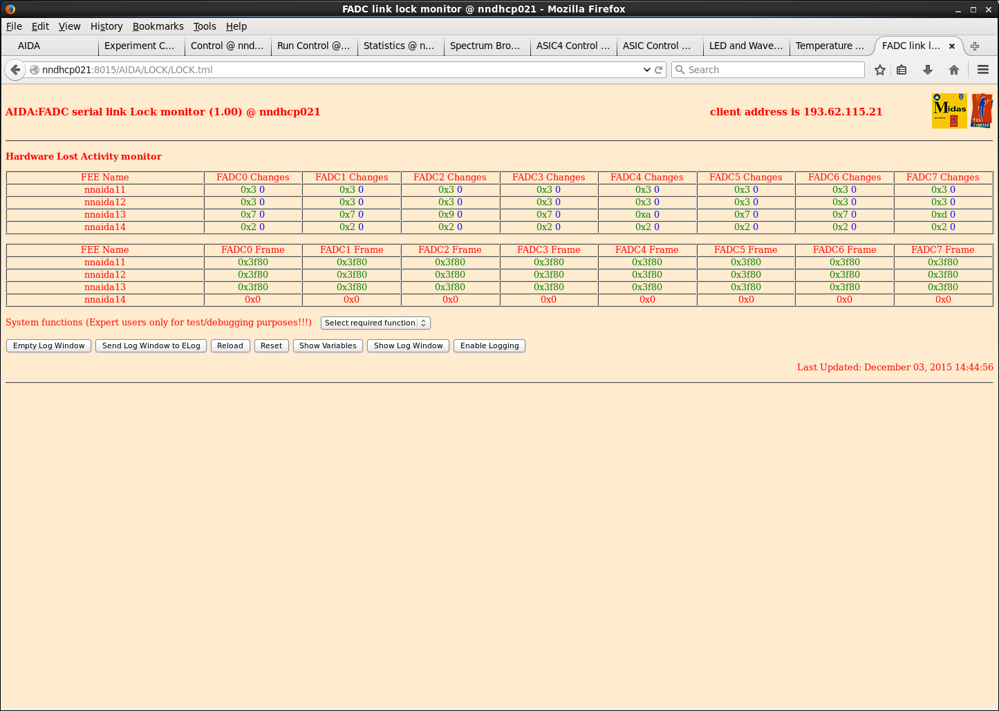
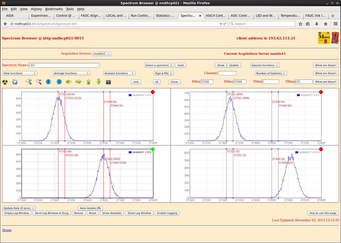
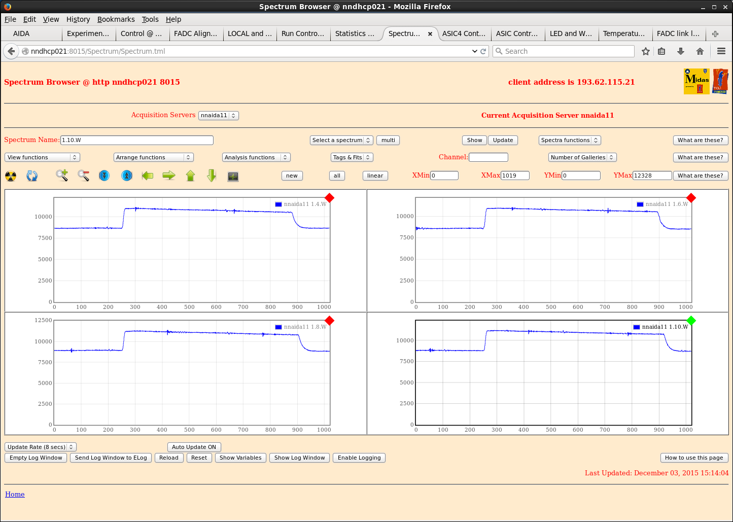
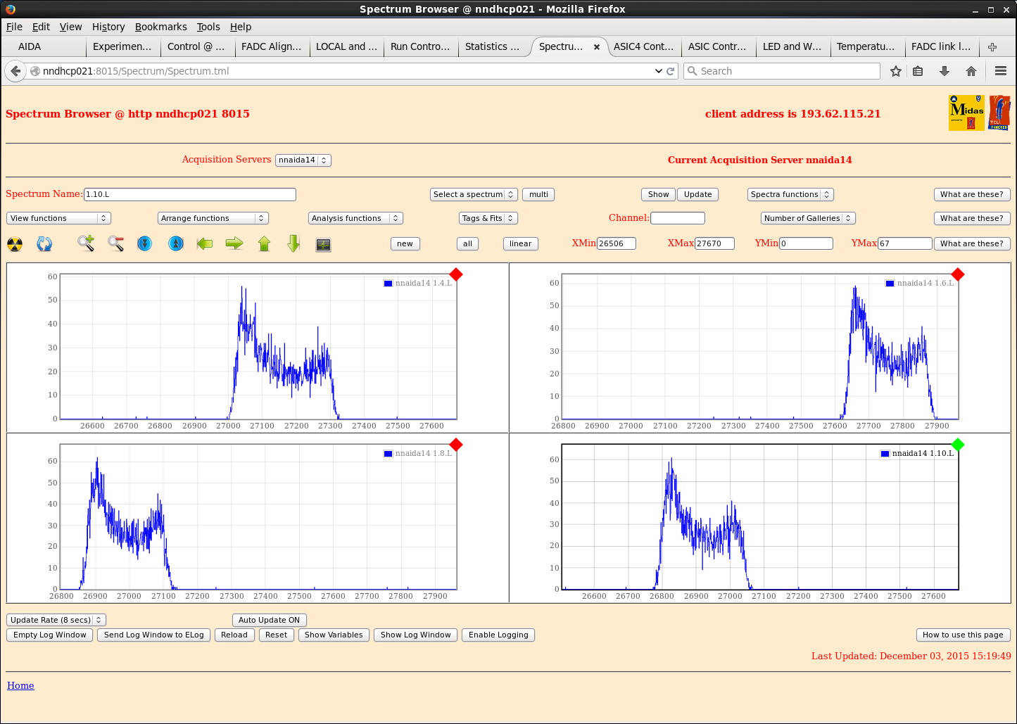
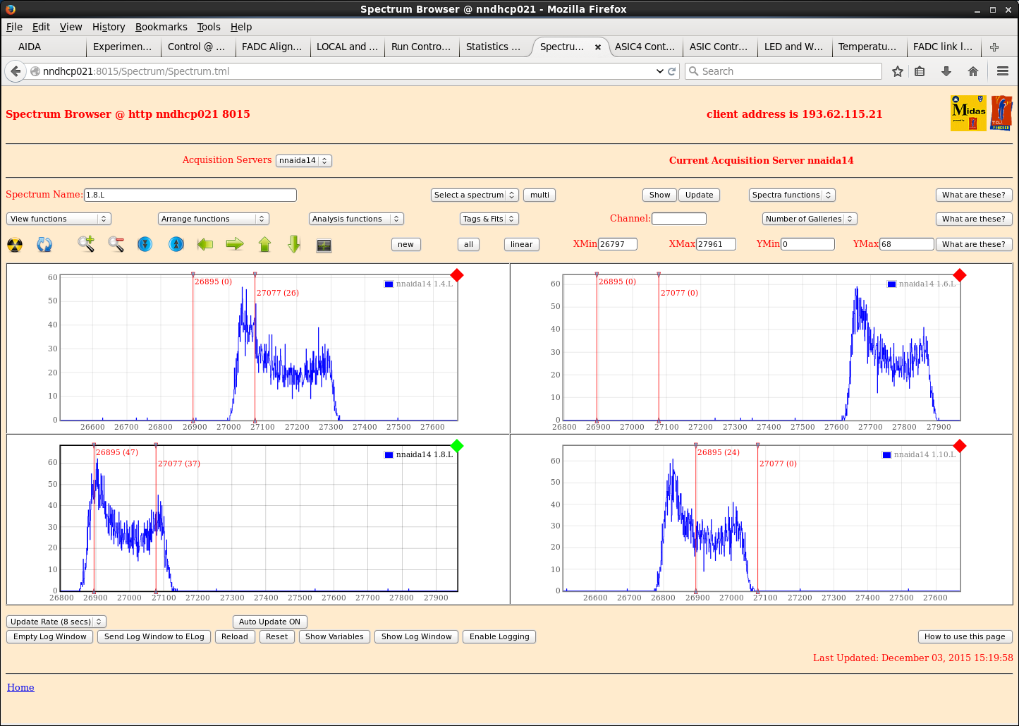
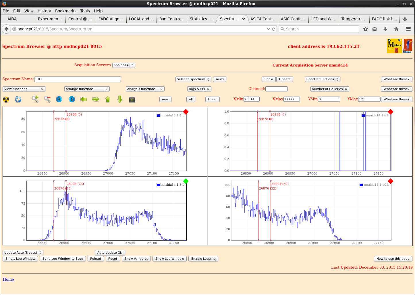
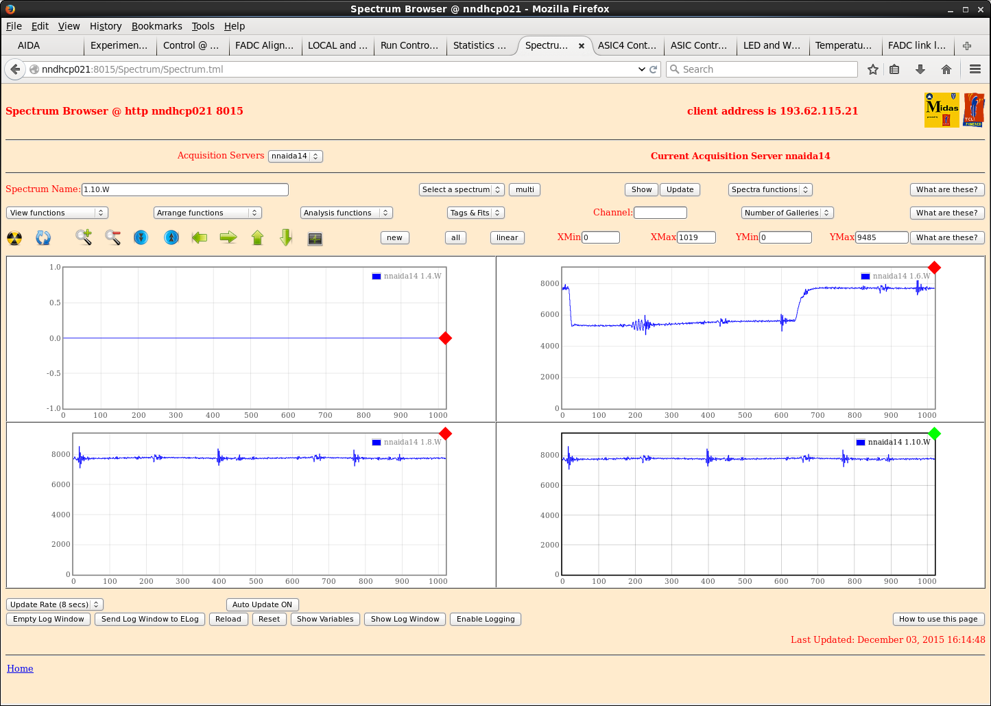
Attachment 1 shows FADC monitor during period in which ADCs in nnaida14 were not calibrated correctly. |
| Attachment 1: nnaida14_noWAV.png
|
|
| Attachment 2: nnaida11_spec_tapeOverGuidePins.png
|
|
| Attachment 3: nnaida11_wav_tapeOverGuidePins.png
|
|
| Attachment 4: nnaida11_spec_tapeOverGuidePins2.png
|
|
| Attachment 5: nnaida11_spec_tapeOverGuidePins3.png
|
|
| Attachment 6: nnaida11_wav_tapeOverGuidePins2.png
|
|
| Attachment 7: nnaida14_spec_doublePeaksChillerOff.png
|
|
| Attachment 8: nnaida14_spec_peakDiffChillerOff.png
|
|
| Attachment 9: nnaida14_spec_chillerOff.png
|
|
| Attachment 10: nnaida11_wav_chillerOff.png
|
|
| Attachment 11: nnaida11_spec_chillerOff.png
|
|
| Attachment 12: nnaida11_specWidth_chillerOff.png
|
|
| Attachment 13: nnaida13_spec_peakDiffChillerOff.png
|
|
| Attachment 14: nnaida13_spec_chillerOff.png
|
|
| Attachment 15: nnaida11_wav_chillerOffTopLoose.png
|
|
| Attachment 16: nnaida14_spec_chillerOffTopLoose.png
|
|
| Attachment 17: nnaida14_spec_chillerOffTopLoose2.png
|
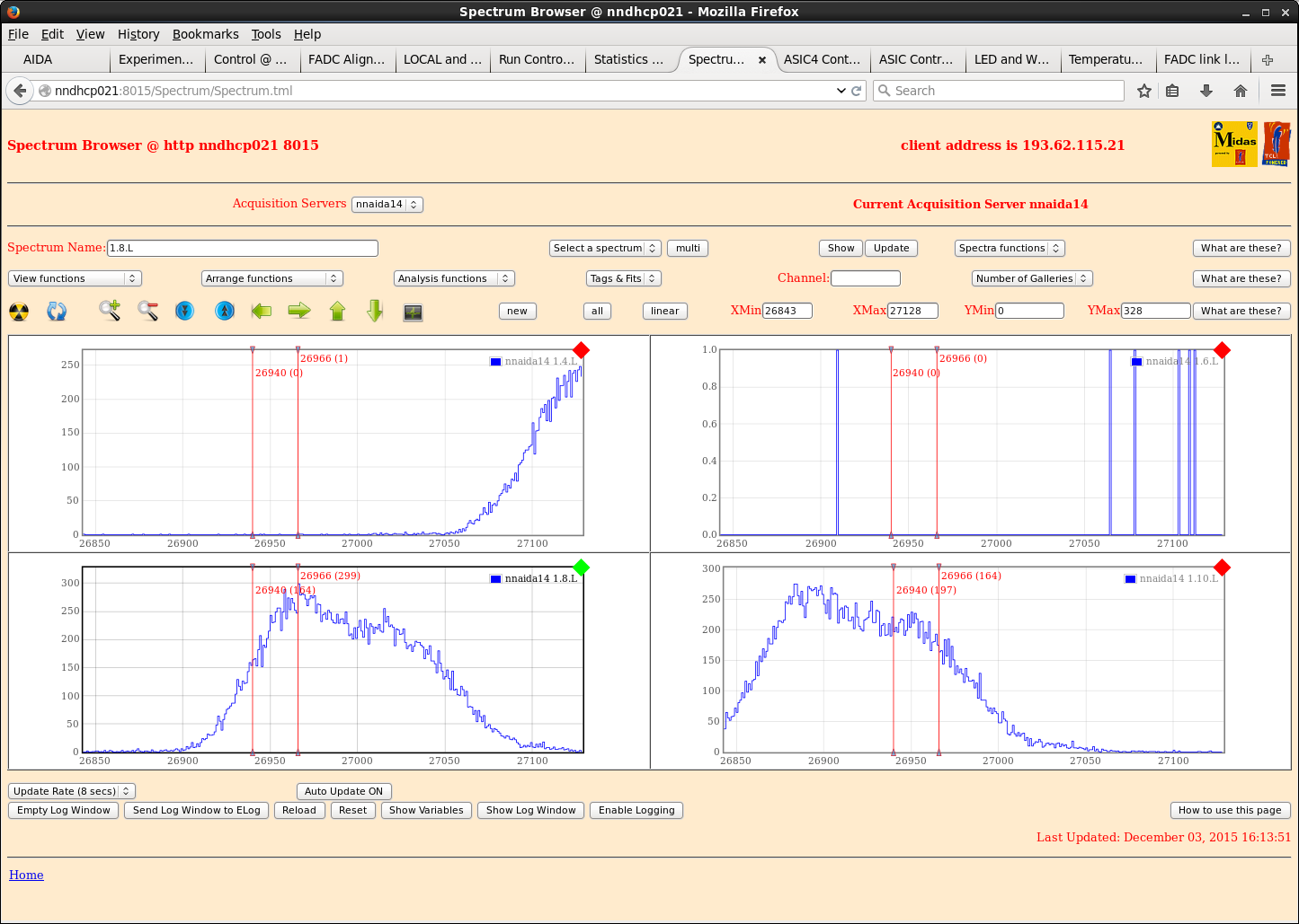
|
| Attachment 18: nnaida14_wav_chillerOffTopLoose.png
|
|
|
|
129
|
Thu Dec 3 10:12:08 2015 |
CG, TD | Report: Low - RPi power cable can't be fully inserted due to case conflict |
The RPi power cable cannot sit fully in the connector, and the lock pins can't engage, because the case gets in the way of the plastic around the end.
As a result we have knocked it out a couple of times and lost power to the system.
Can this be modified or can we get a new case/cable that resolves this issue? |
|
|
128
|
Wed Dec 2 18:39:44 2015 |
CG | New Kapton cable tests at DL |
Powered on system ok.
Electrical connection between crate and mezzanines still persists, but only to the top cool plate (no connection to the bottom or sides), eith resistance ~5-10 ohms
Seems to have no effect on performance though as without the kaptons connected, still see pulser widths of ~14ch at t_shape = 8us.
Connecting cables reinstates double peaking in n-side.
Without HV or detector connected, nnaida13+14 gibe single Gaussian peaks of width ~45ch, with almost perfect waveforms.
- Patrick saw this too, I'm not going crazy, but on zeroing histograms (didn't change a single other thing) it went back to having double peaks again.
Replaced nnaida13 shielded kapton with unshielded one to see if that is causing this effect
- still see double peaking but width of tallest peak is down by ~25% (likely just due to capacitance)
With shielding on, do see much noisier waveforms however.
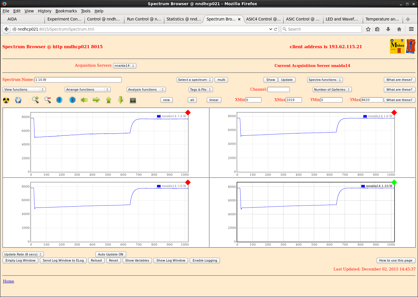
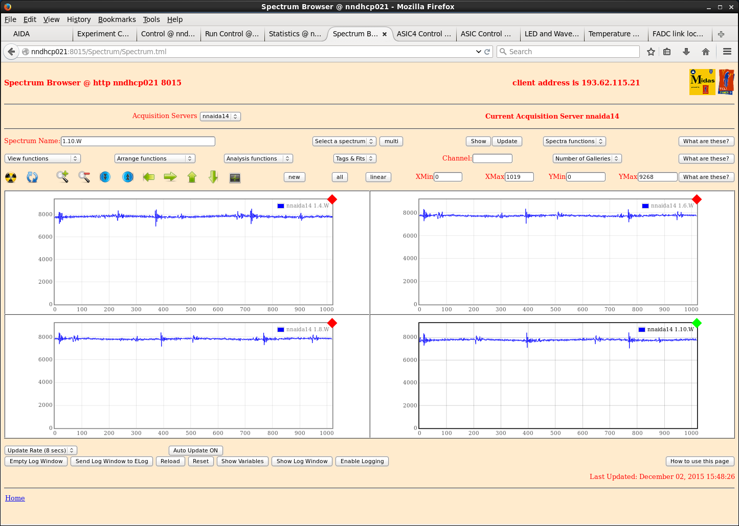
- note: attachments 1 and 2 were taken using exactly the same threshold of 512. When shielded, bumping this up to 1000 still made little difference and 'actual' traces were only caught ~25% of the time
Changed firmware to V8.
No difference in performance.
|
| Attachment 1: nnaida14_wav_noHVnoDetNoShielding.png
|
|
| Attachment 2: nnaida14_wav_noHVnoDetWithShielding.png
|
|
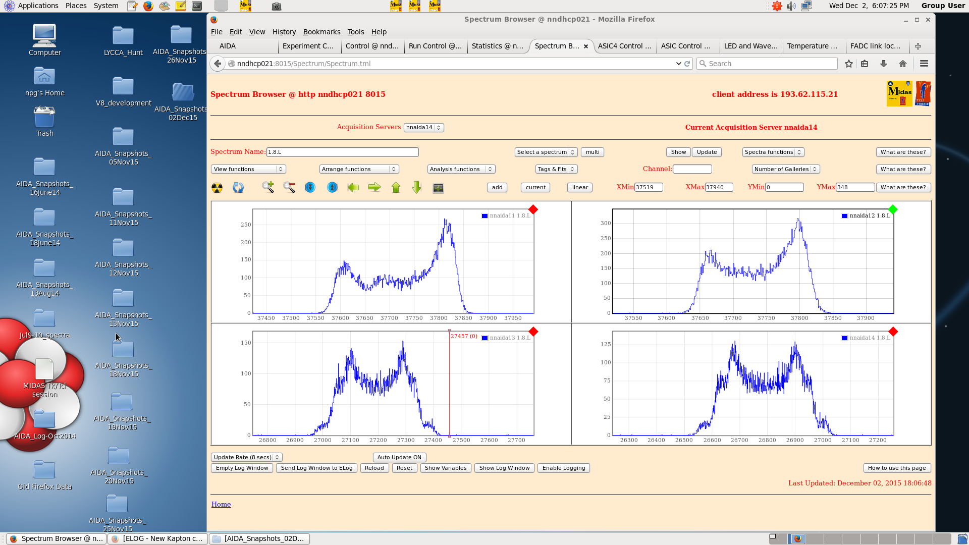
| Attachment 3: all1.8.L_noDetShaping2us.png
|
|
|
|
127
|
Thu Nov 26 16:32:52 2015 |
CG, TD | New Kapton cable tests at DL |
Powered on system without issue. biased detector to -200V. Leakage current not stable, bouncing around between ~3.66 - 3.74uA. Room temp 22.0oC -> Peak widths similar to yesterday.
Changed through various permutations of jumper connections (field planes, detector grounds, bias ground reference).
The only change that led to any change in performance was the removal of the bias ground reference jumper, this made the waveform noise much worse and increased peak widths (attachment 4).
Changed the network cables to unshielded (no ground connection) ones. No difference in performance.
Connecting thick Cu braid from NIM bin chasis to LEMO connectors makes noise worse.
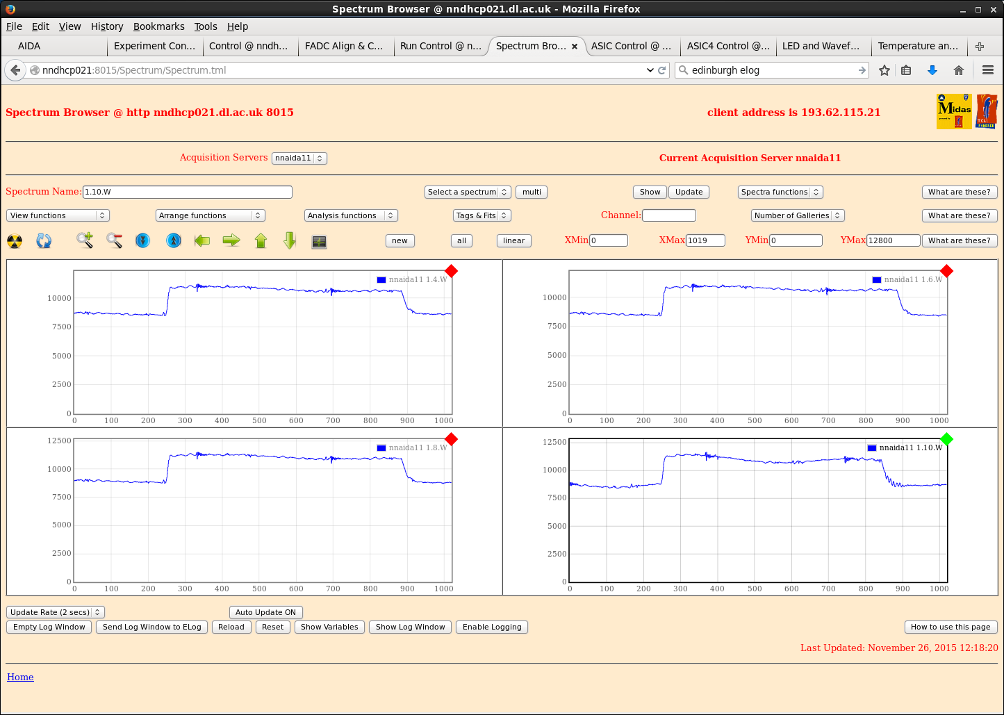
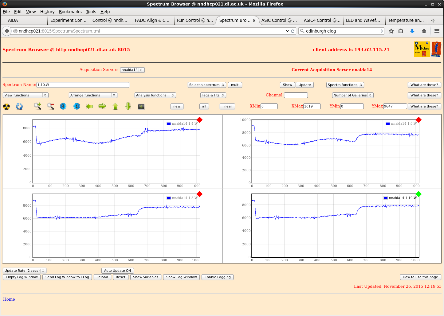
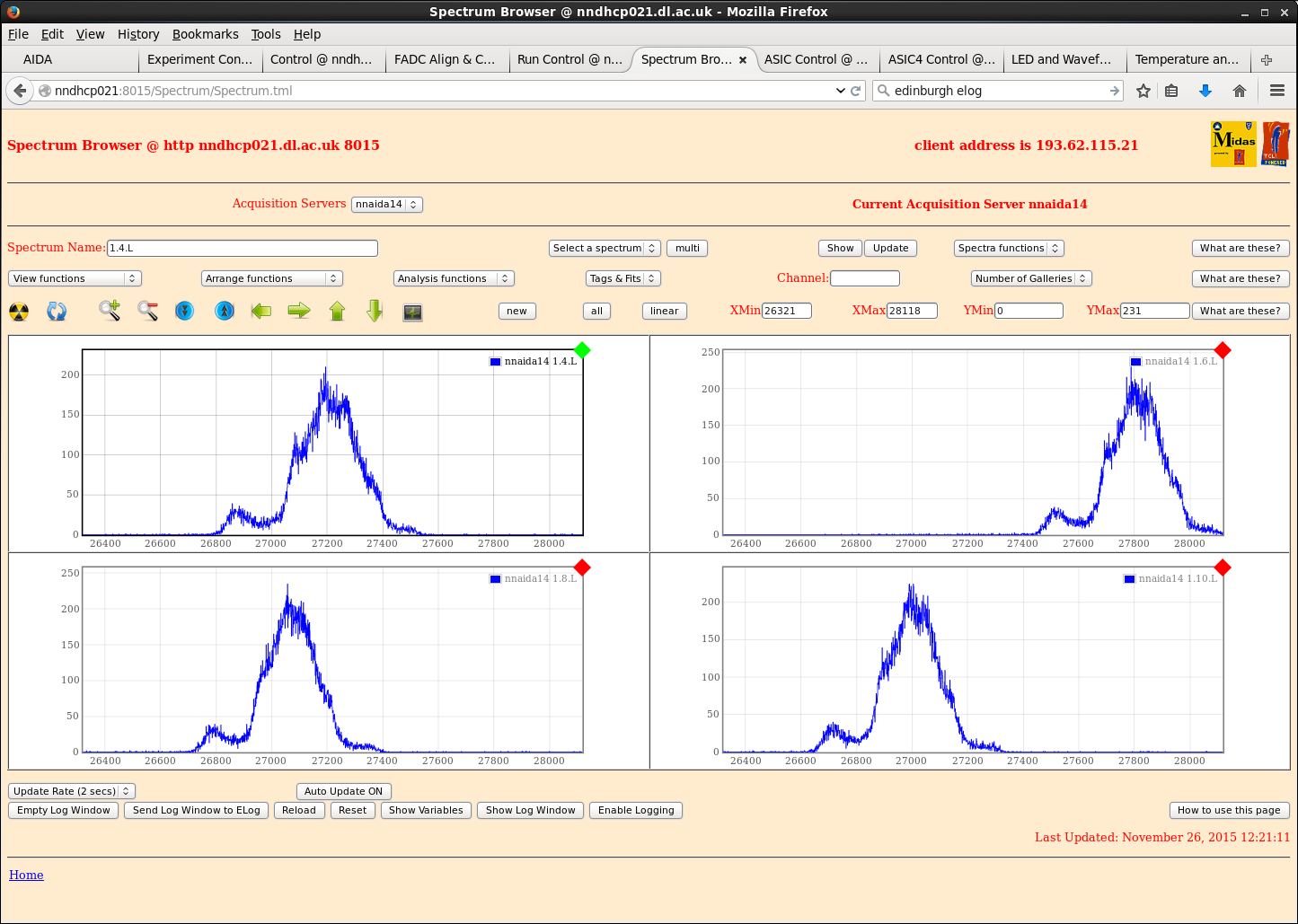
Moving this braid to the PSU case made peak widths larger and waveform noise in nnaida14 much worse. Traces do not return to baseline after a pulser event (attachment 2+3)
Reduced bias to -100V in an attempt to stabilise the jumpy leakage current -> made it worse.
Increased to -250V and the leakage current stability improved -> fluctuations of < 0.10uA @ 4.985uA.
Connected Al detector box with thick braid to braid connecting HV and pulser input -> no difference.
Replaced metal detector box with cardboard box so it was floating -> no difference.
Made sure kaptons were all separated with sheets of paper to prevent electrical contact of shielding -> no difference.
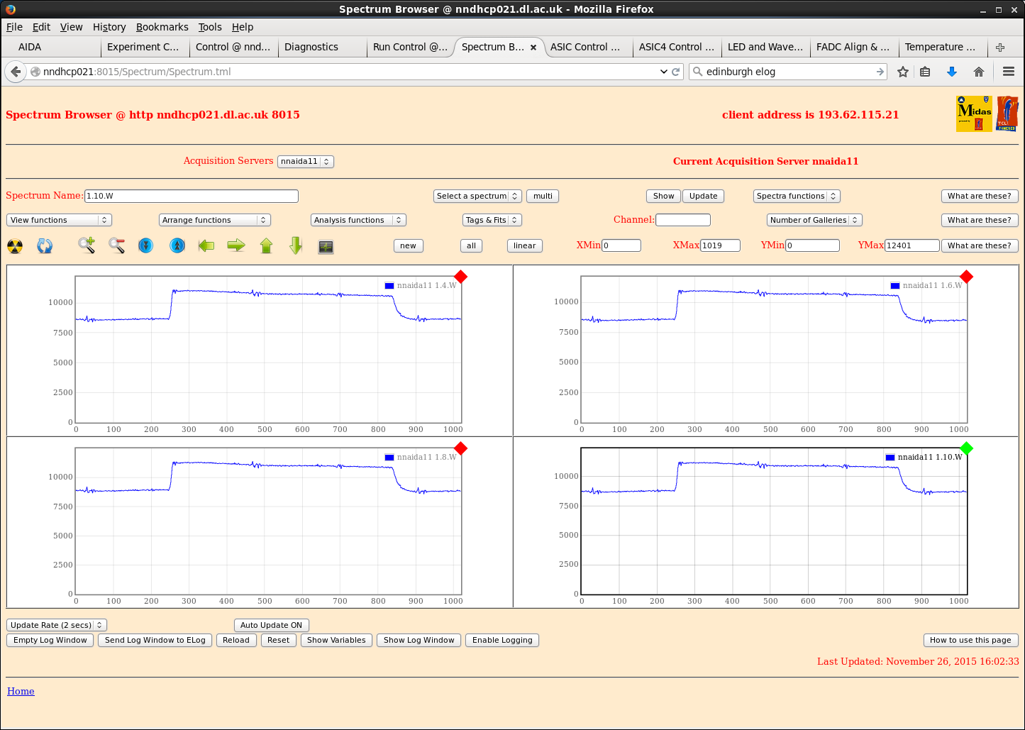
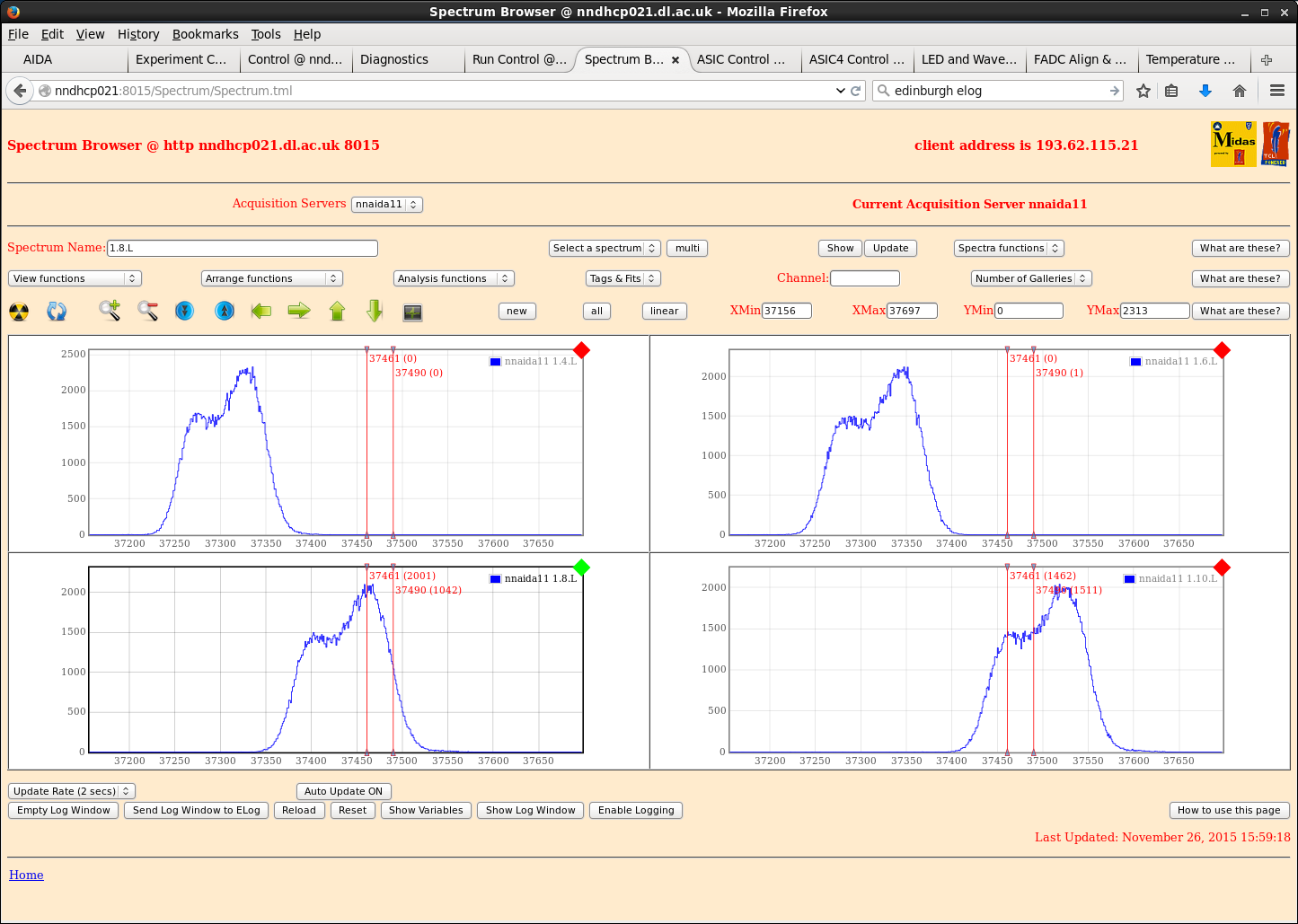
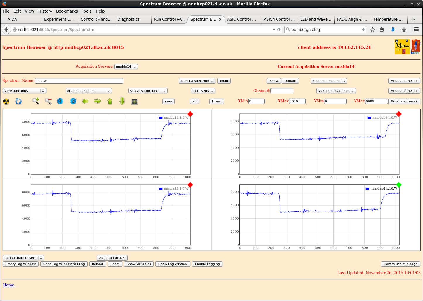
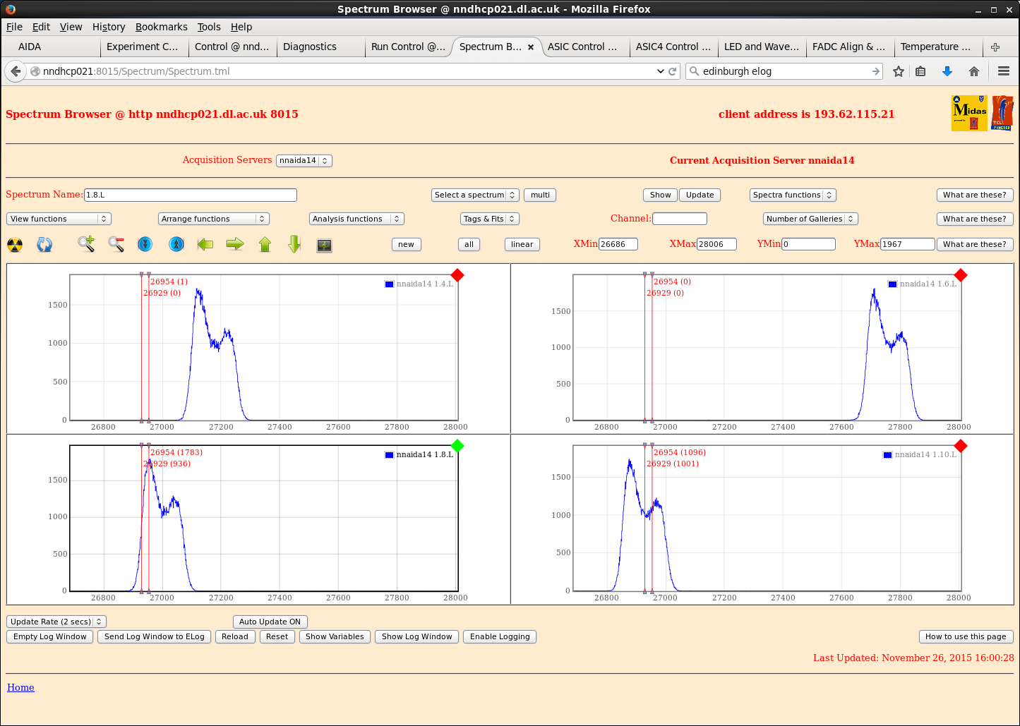
Disconnected detector and found double-peaking remains => this is not a detector issue, but intrinsic to the kaptons (with the kaptons removed, we observe Gaussian peaks of width ~14ch) (attachments 5-9).
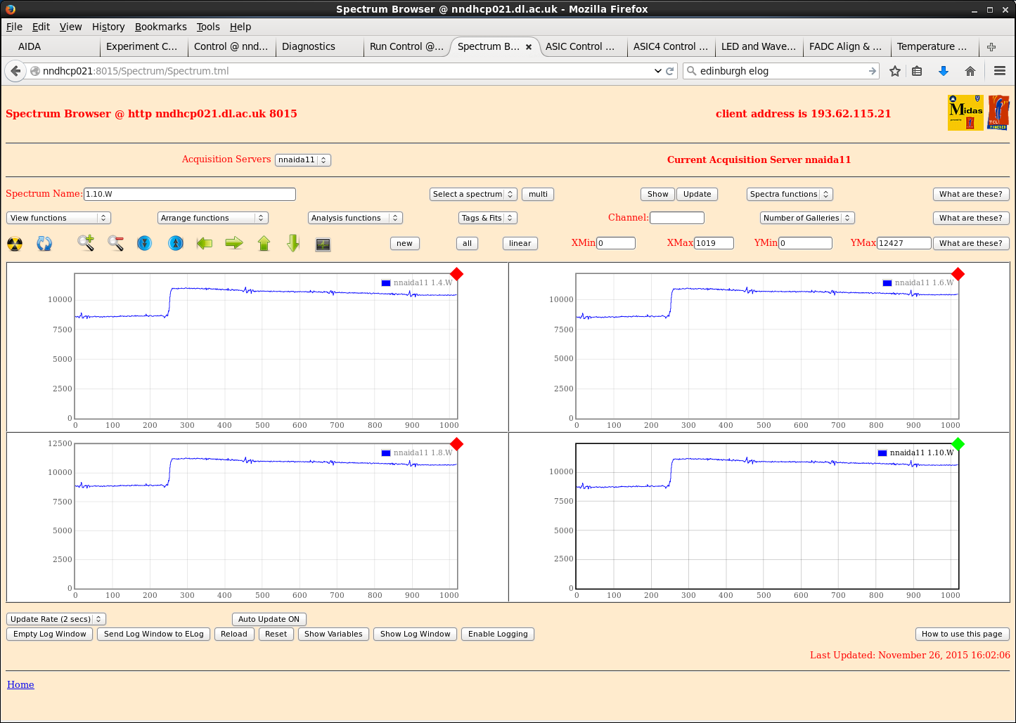
Occasionally, waveforms fail to reset correctly (attachment 7).
Cu mezzanine block and Al crate now no longer isolated from each other. Resistance between them ~6 Ohms with crate locked up, increases to ~300kOhms when crate opened. |
| Attachment 1: nnaida11_wav_braidToPSU.png
|
|
| Attachment 2: nnaida14_wav_braidToPSU.png
|
|
| Attachment 3: nnaida14_spec_braidToPSU.png
|
|
| Attachment 4: nnaida11_wav_biasGroundRefJumperOff.png
|
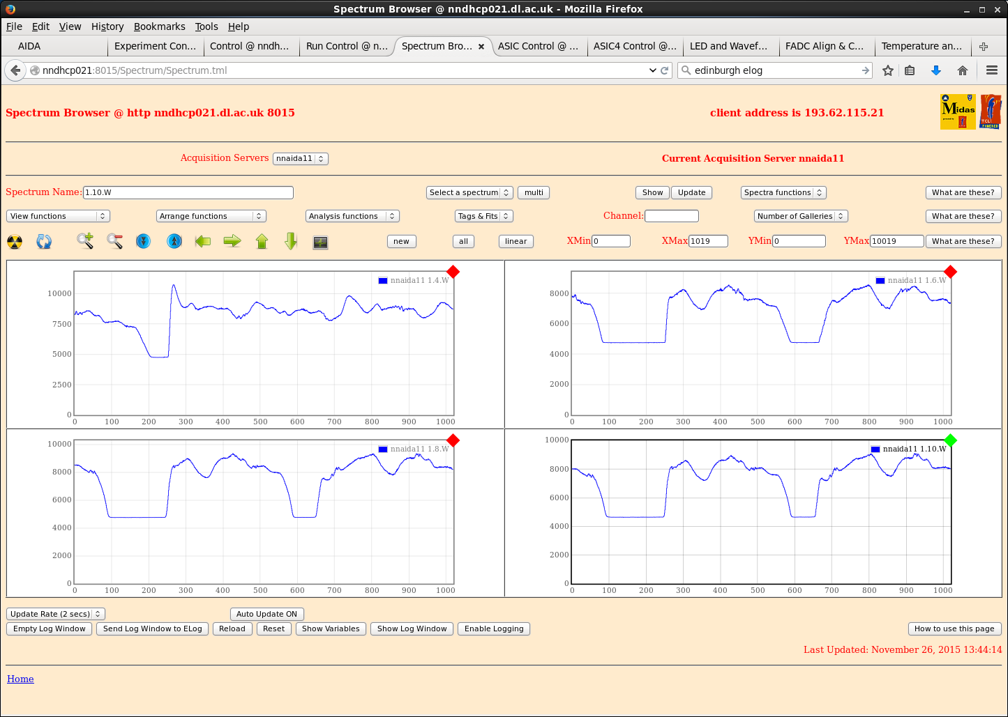
|
| Attachment 5: nnaida11_wav_noDetector.png
|
|
| Attachment 6: nnaida11_spec_noDetector.png
|
|
| Attachment 7: nnaida11_wav_notResetting.png
|
|
| Attachment 8: nnaida14_wav_noDetector.png
|
|
| Attachment 9: nnaida14_spec_noDetector.png
|
|
|
|
126
|
Wed Nov 25 19:24:39 2015 |
CG, TD, PJCS | New Kapton cable tests at DL |
Powered system on and biased to +200V at room temp of 22.4oC. Leakage current of 3.37uA.
Waveforms very noisy and spectra dominated by low E noise. Upon taking a close look at front end found one of the kaptons to have broken a connection. Swapped it out for a spare.
Returned to same situation as last week. Peaks all have a shoulder at t_shape of 8us, but main peak has width ~80ch. Shorter shaping times lead to double peaking.
Removed FEEs from crate and properly seated adapter PCBs on Cu mounting block, with washers between plated part of PCB and allen screw.
- <0.4 ohm impedance betwee Cu mount block and washer/screw but ~20 ohms between screw and LEMO connector => 20 ohms between Cu mounting block and LEMO connectors
- plating around screw holes doesn't go anywhere.
Confirmed LEMOs are connected to ASIC ground (as they should be) on the Cu mezzanine block with <0.2 ohm impedance between mezzanine Cu and LEMO connectors.
With adapter PCBs removed, Cu mezzanine blocks of separate modules still have impedance < 0.3 ohm between them. How/why?
- found out MACB cables, power cables and network cables all connect the grounds of each FEE card/module. Was this expected? Does this cause us problems?
Swapped non-functioning nnaida12 for the former nnaida11 from the module featuring the other broken nnaida12 - all seems to work, although no waveforms are produced.
Very low impedance between ASIC grounds of FEE cards in same module.
To obtain a better ground connection between the ASIC grounds of separate modules, connected a thick braid to Cu mezzanine block of each. Operating at limit of multimeter so no noticeable difference in impedance. But...
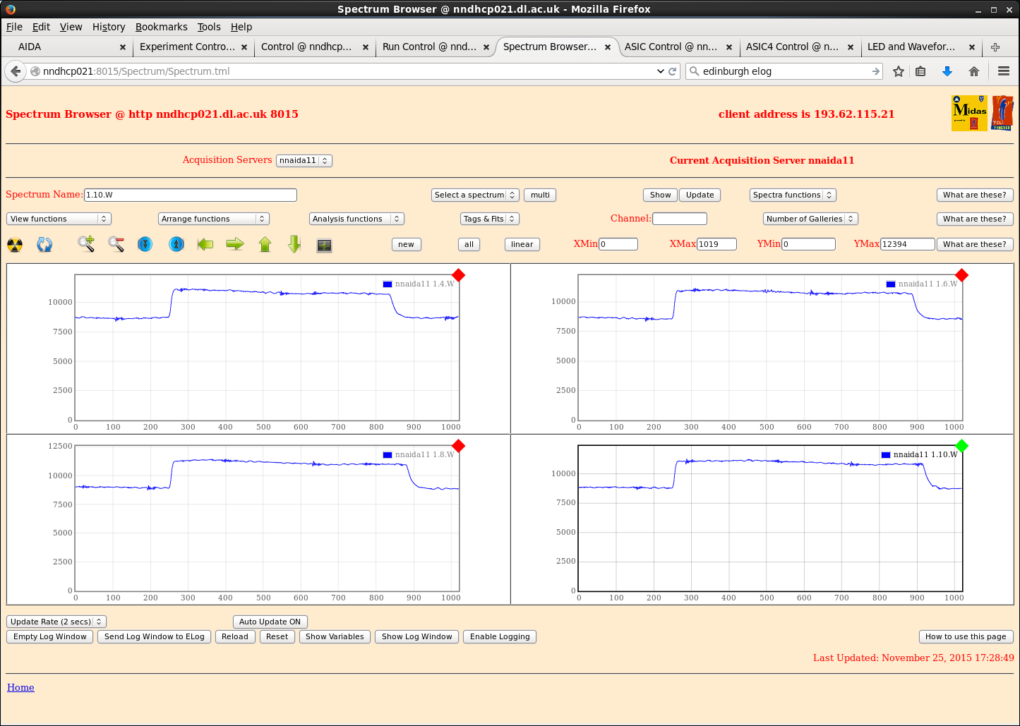
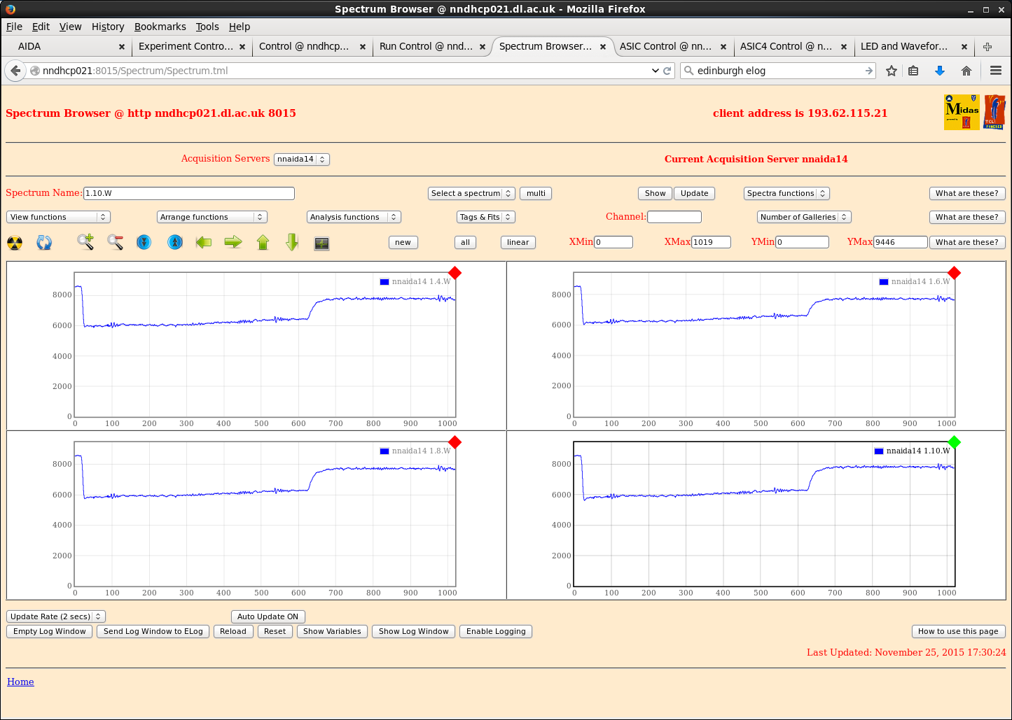
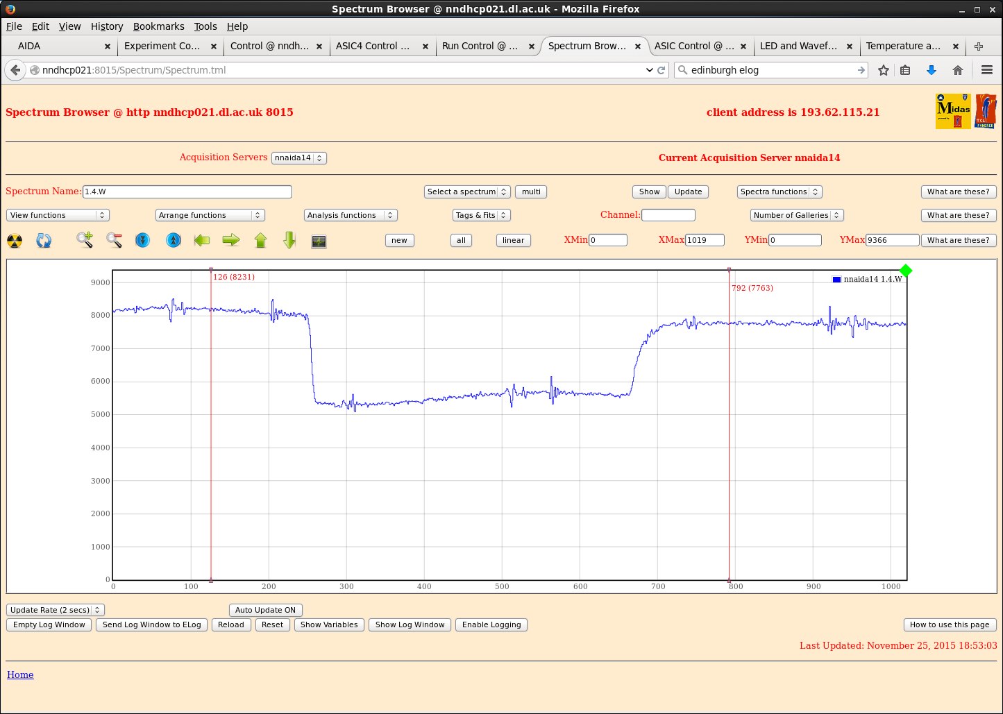
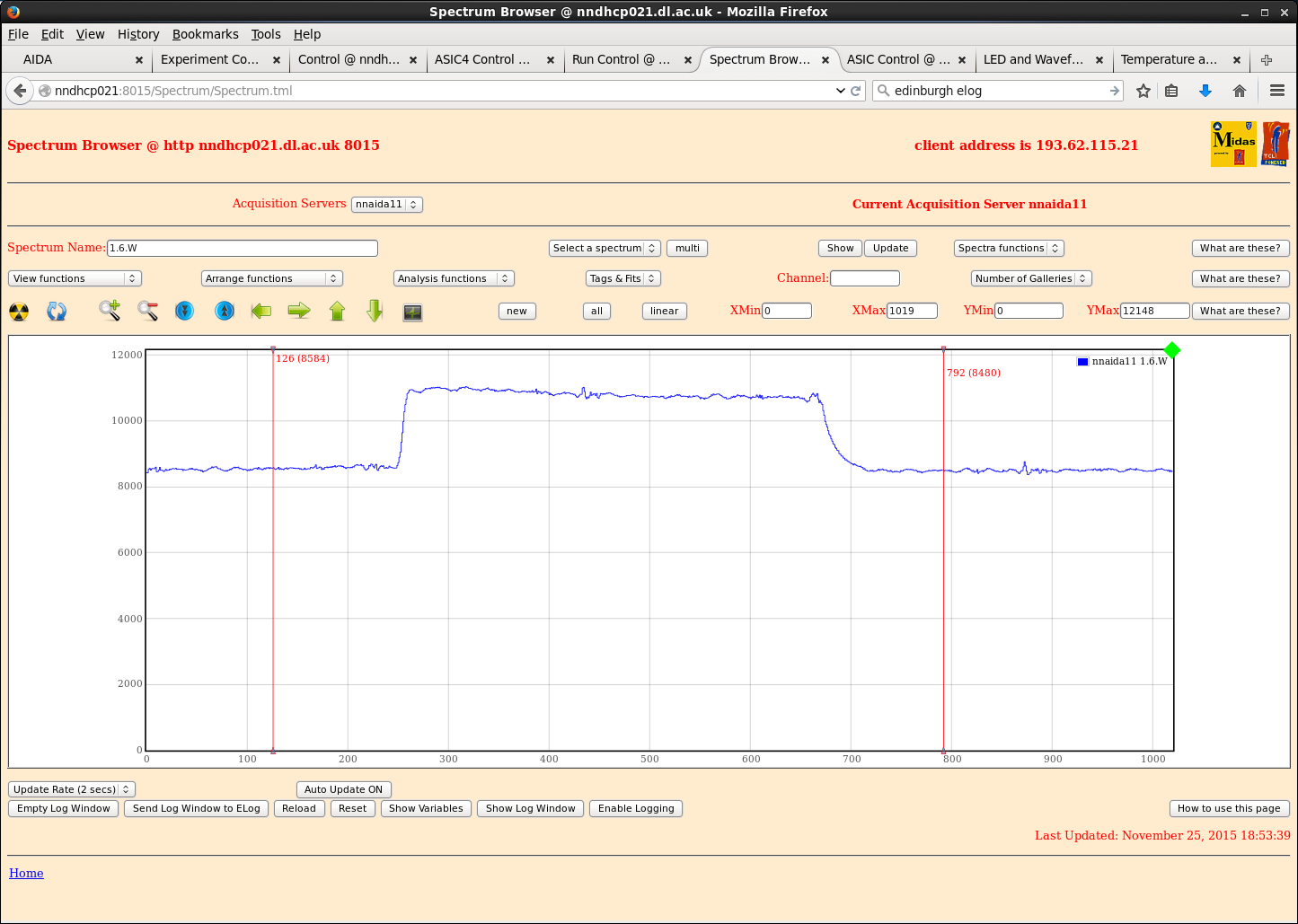
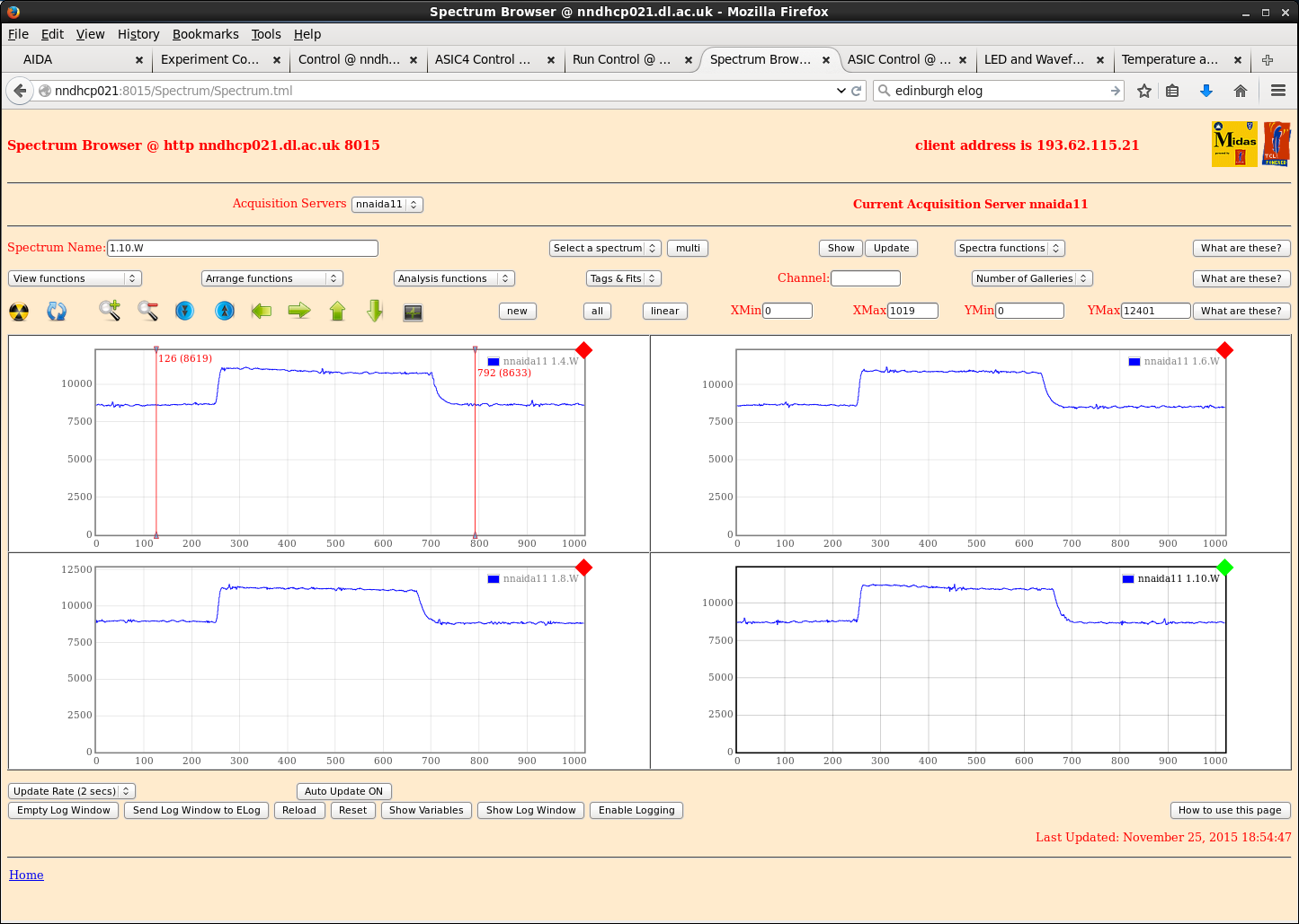
With mezzanines connected and thick braid connecting HV and pulser at LEMO connectors, see the best waveforms so far; very little noise, some transients (attachments 1+2).
However, in nnaida14 waveform does not get back to baseline properly after a pulser event (attachments 2+3).
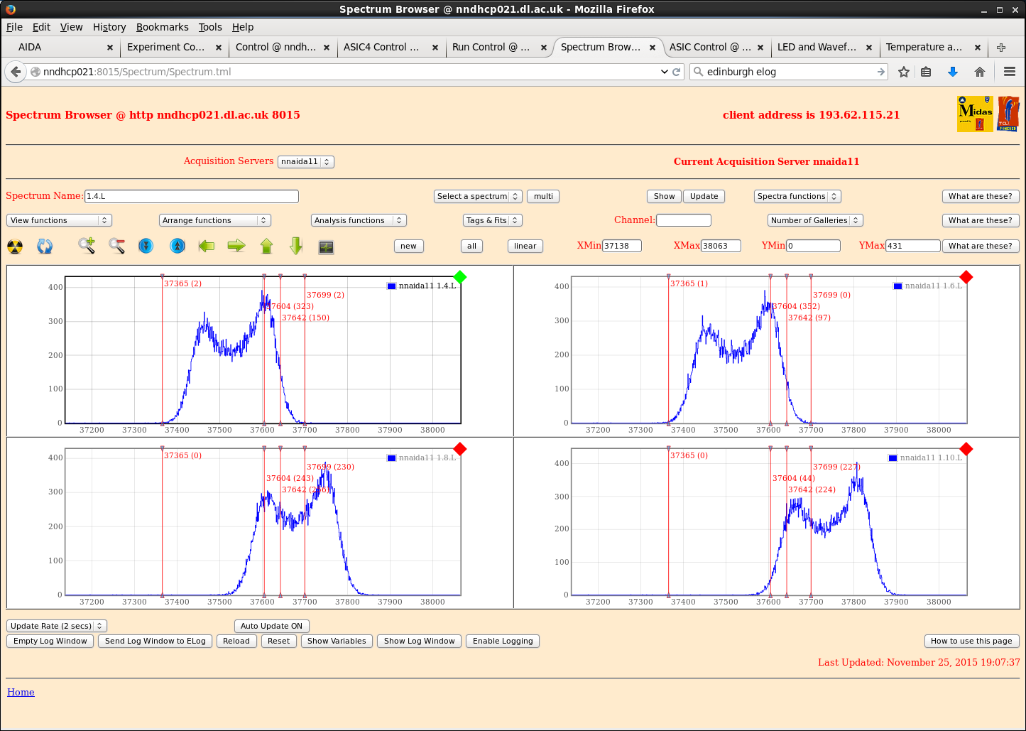
Despite very clean waveforms, still see double-peaking in spectra, although peak widths are fairly low (attachment 6).
|
| Attachment 1: nnaida11_wav_mezzConnectedPlusThickBraid.png
|
|
| Attachment 2: nnaida14_wav_mezzConnectedPlusThickBraid.png
|
|
| Attachment 3: nnaida14_wav_resetDiff.png
|
|
| Attachment 4: nnaida11_wav.png
|
|
| Attachment 5: nnaida1_wav_multi.png
|
|
| Attachment 6: nnaida11_spec4us.png
|
|
|
|
125
|
Fri Nov 20 16:29:49 2015 |
CG | New Kapton cable tests at DL |
Powered system up from state it was left in last night. Biased to +200V with leakage current 3.9uA @ room temp 23.3oC.
nnaida14 now performing as it was at the beginning of yesterday, with nnaida11 back to having noisy waveforms.
Tried various combinations of grounding to ascertain minimum possible configuration to maintain (or improve) current performance.
- detector ground jumper required, noise in waveforms increases significantly if removed
- system seemingly has no preference of jumper combinations for the left-hand pairs of pins, other than all 4 at once increase noise. Any combination of 3 or fewer seems to have no effect
- fitted additional small braids to kaptons and took them directly to the PCBs (like in the previous ELog entry) which made no difference
Found LEMO connectors on both PCBs to show open circuit with the Cu adapter mount block (not mezzanine block). Wrapped thin braid round connectors and took attached directly to each respective Cu block.
Resistance between any two points between the detector and Cu mezzanine blocks now < 0.5 Ohm.
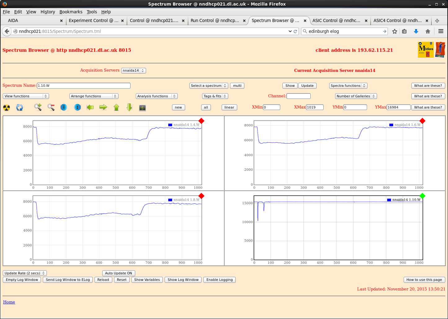
- when i left for lunch this had no effect on nnaida11, but nnaida14 showed improvement in fine noise on waveforms but none for the low frequency 'wave' (see attachment 1)
- after returning from lunch, both were noisy again and I was unable to repeat original improvement over a few attempts at the same or similar grounding. Subsequently removed completely and performance returned to normal...
When we arrived on Wednesday, detector box was floating and performance was OK. Box is now not floating, and attempts to make it so were unsuccessful, although nothing I did changed the noise situation.
Removing the Al plates either side of the detector made had no impact on the noise.
Didn't get chance to try swapping the PCBs over. |
| Attachment 1: nnaida14_goodGNDbetweenAll.png
|
|
|
|
124
|
Thu Nov 19 17:31:24 2015 |
CG, TD | New Kapton cable tests at DL |
Powered system on from the state it was in last night. Biased to +200V with leakage current 3.9uA at room temp 22.8oC.
Performance of nnaida14 at shaping time of 8us slightly worse than last night - peak now non-Gaussian and double peaked. New source of noise?
Trying different permutations of grounding options initially led to no improvements.
- tried various jumper combinations and taking the braids from the kaptons to various different points on the adapter PCBs - no appreciable changes.
However, connected the braids from the kaptons to the thick Cu braid with a crocodile clip and the noise in the back side FEEs significantly reduced.
Throughout, both sides of the detector saw improvements, but the front side performed much better than the back (rear waveforms were still just noise, just slightly reduced noise).
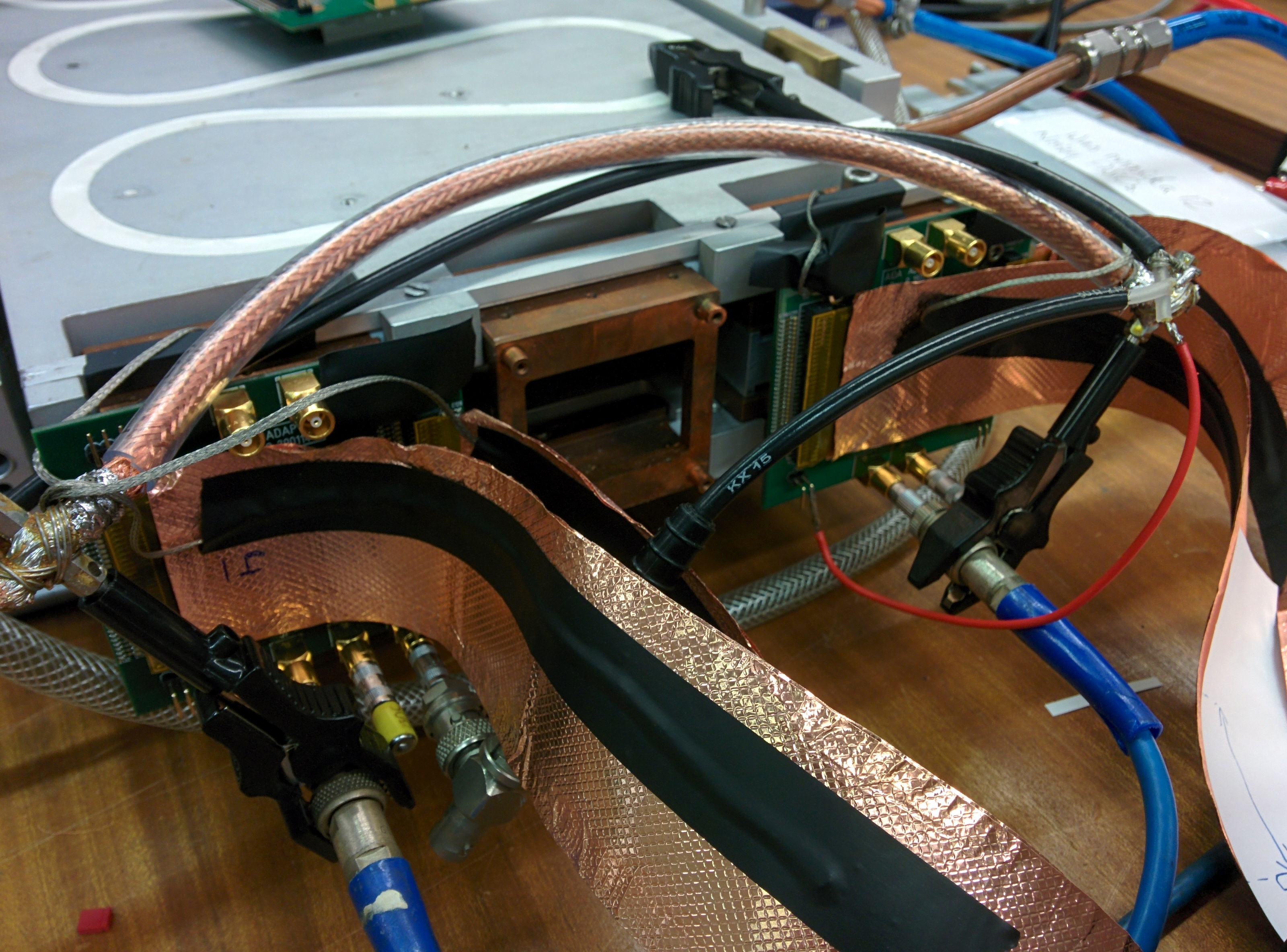
Soldered 4 drain wires to the thick Cu braid to improve connection and taped them to the Cu tape on the kaptons so as to give the shortest possible distance between kapton and thick braid (attachment 2).
- performance in nnaida11 improved dramatically, the waveforms looked sensible instead of just noise (see attachment 1)
- however, nnaida14 waveforms have now just gone to noise... We have swapped the performance of the front/rear strips.
In investigating this, we have found poor connections and high resistance between the Cu blocks and adapter PCBs, despite all screws connecting them -> a good connection cannot always be assumed it seems.
However, taking a braid from the PCBs directly to the Cu blocks makes little difference to performance. Neither did putting an Al plate on the front of the detector.
The Al detector box was previously floating, but now is not - the effect of this will be investigated tomorrow. |
| Attachment 1: nnaida11_wav.png
|

|
| Attachment 2: IMG_20151119_162831.jpg
|
|
|
|
123
|
Thu Nov 19 12:23:03 2015 |
CG, TD | Report: Low - Error message when selecting Act on all FEE64s for FADC calibrate |
When trying to calibrate FADCs in FADC Align and Control page, ticked 'Act on ALL FEE64 modules'.
Error message displayed (attachment 1) and, despite 'Act on ALL' box being ticked, was only able to act on one FEE64 at a time. |
| Attachment 1: FADC_actOnAll.png
|
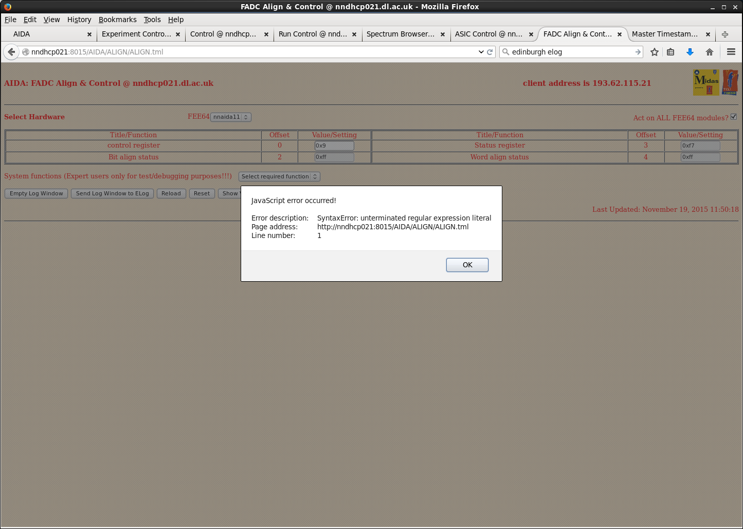
|
|
|
122
|
Thu Nov 19 12:19:15 2015 |
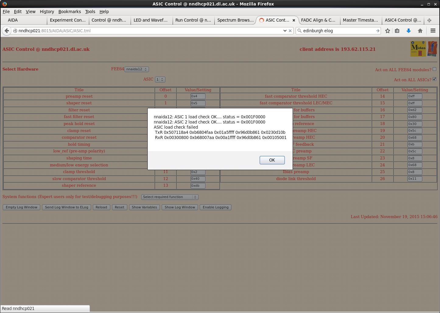
CG, TD | Report: Low - nnaida12 ASIC4 not functioning |
Current nnaida12 (MAC address 2b:09:e8) has several noisy channels in ASICs 1-3, whilst ASIC4 does not work at all.
Frequently, but not always, ASIC4 fails to load/check.
Additionally, fast discriminators are turned off in settings but show activity in the Hit spectrum. |
| Attachment 1: nnaida12_stats.png
|
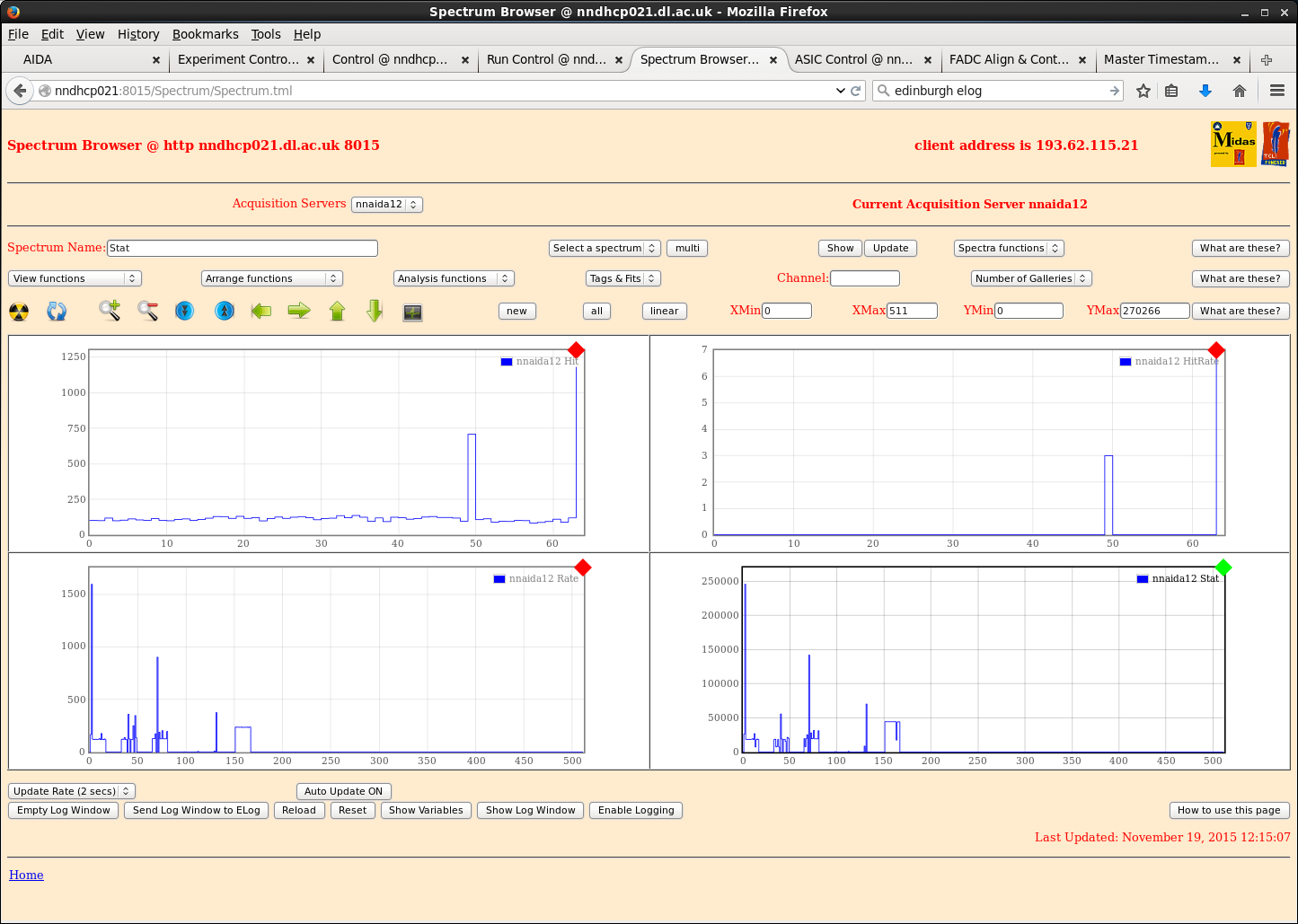
|
| Attachment 2: nnaida12_ASIC4_checkError.png
|
|
|
|
121
|
Wed Nov 18 18:18:26 2015 |
CG, TD | New Kapton cable tests at DL |
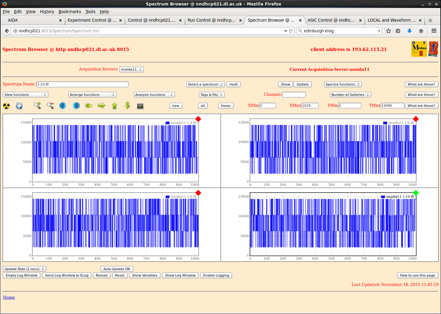
Note: kapton #7 may have broken pins next to (deliberately) broken ground pin. Unclear, but should not be used for bias until certain.
Detector BB18 2998-22 connected via 4 45cm kaptons and biased to +200V via nnaida12+14, with leakage current 4.310uA @ room temp 25.4oC.
Turned off FADCs as per PCS instructions in previous entry - no change. Turned back on.
Braid grounding HV to pulser and all jumpers removed - makes performance much worse.
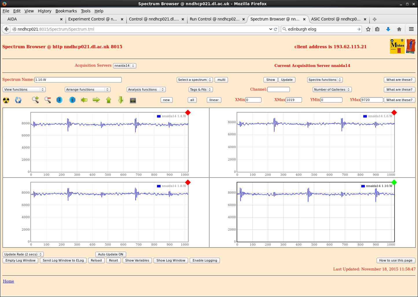
Connecting only jumper to ground detector brings performance back to moderate, but not good. Re-adding braid bring further improvement.
- other jumpers don't seem to have a considerable affect on performance.
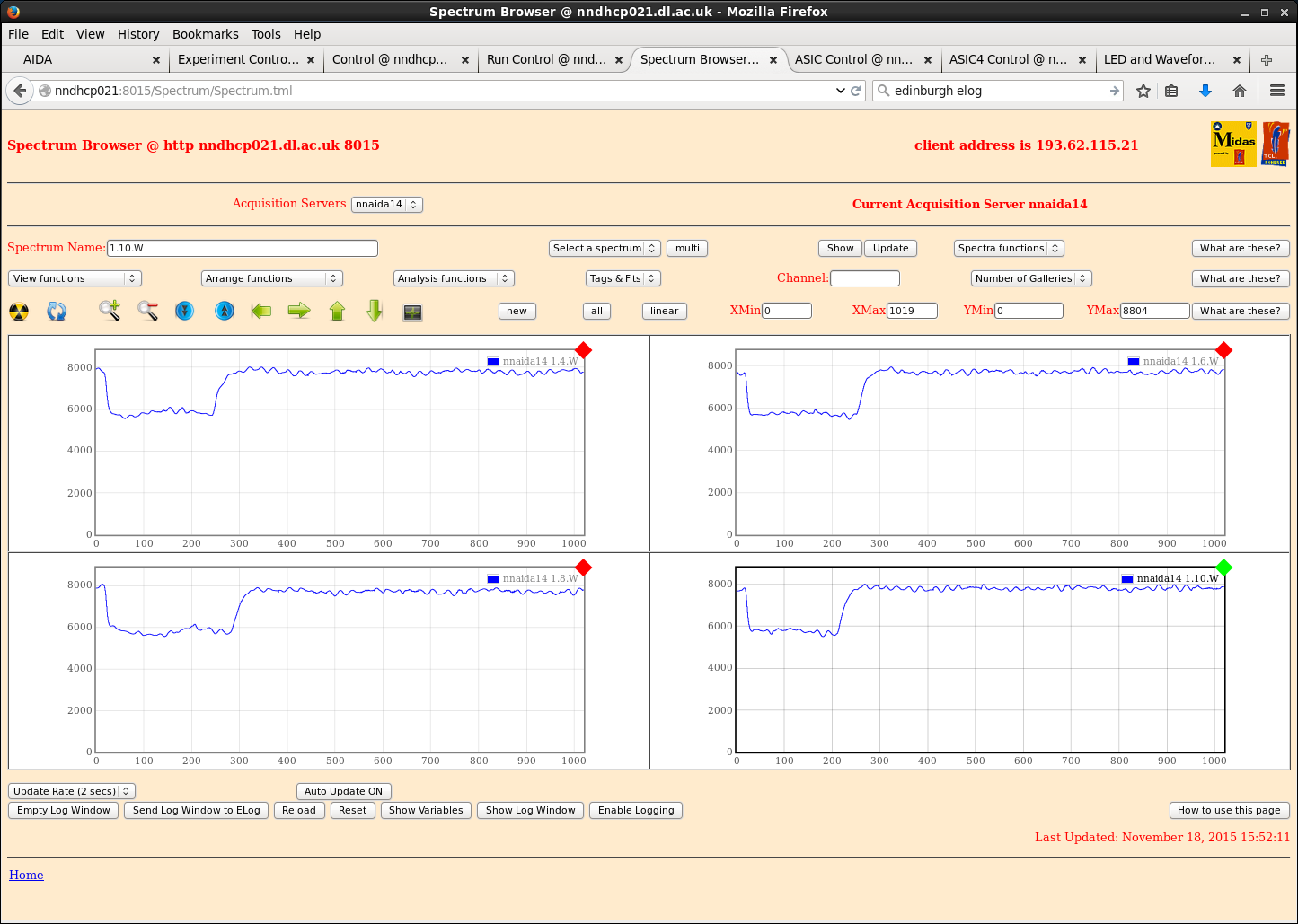
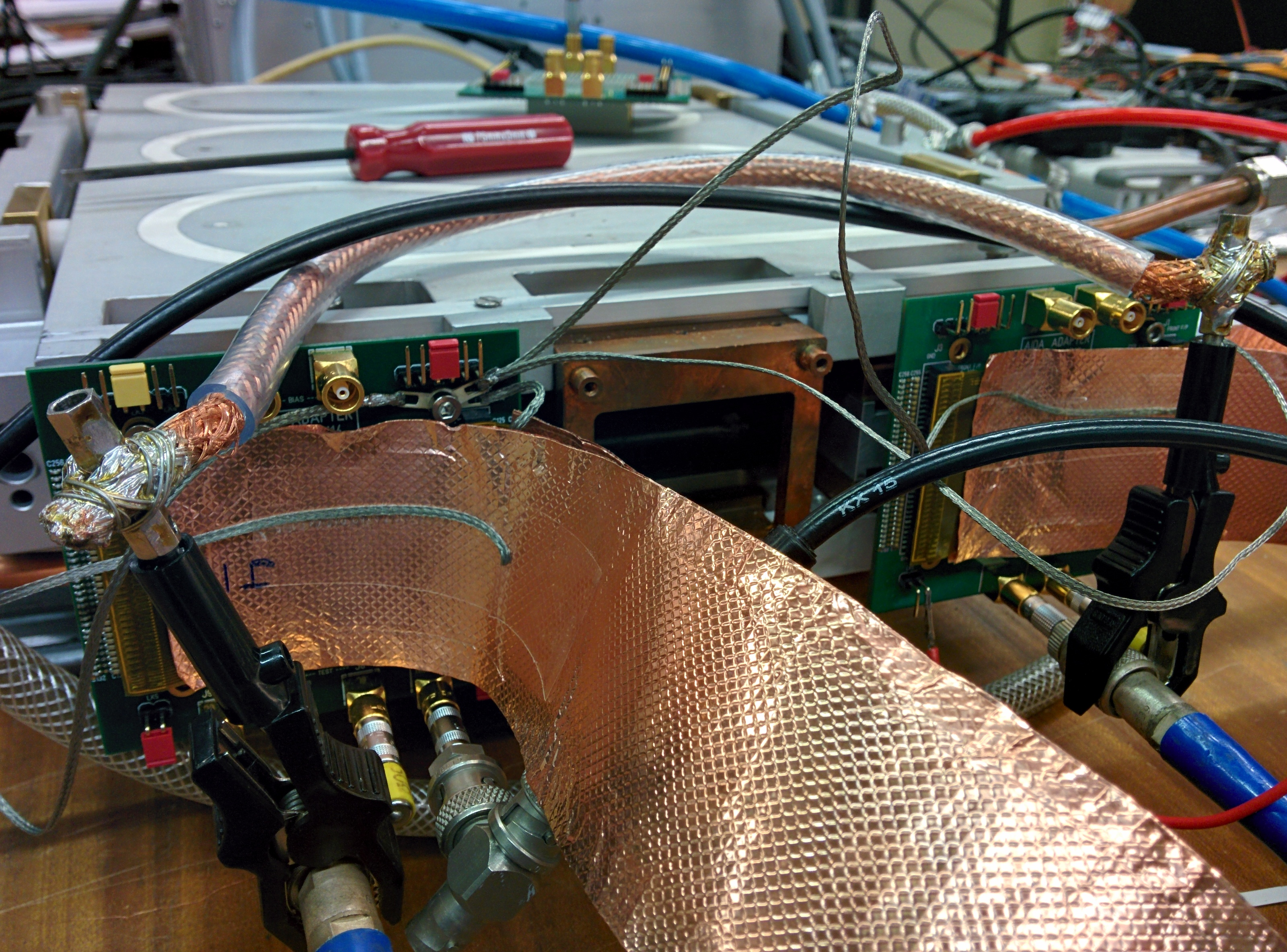
Added short (~few cm) drain wire to outside of Cu tape covering kaptons and attached to nearest allen bolt in adapter PCB, i.e. at the top of each connector, plus the jumper for the detector ground. Looked at variation with shaping time:
t_shape (us) || 0.5 | 1.0 | 2.0 | 4.0 | 8.0
Pulser FWHM (ch) || 715 | 687 | 448 | 246 | 124 (nnaida14)
- all peaks were non-Gaussian and double peaked apart from at 8us. @ 8us it was not quite Gaussian, but much closer than the rest.
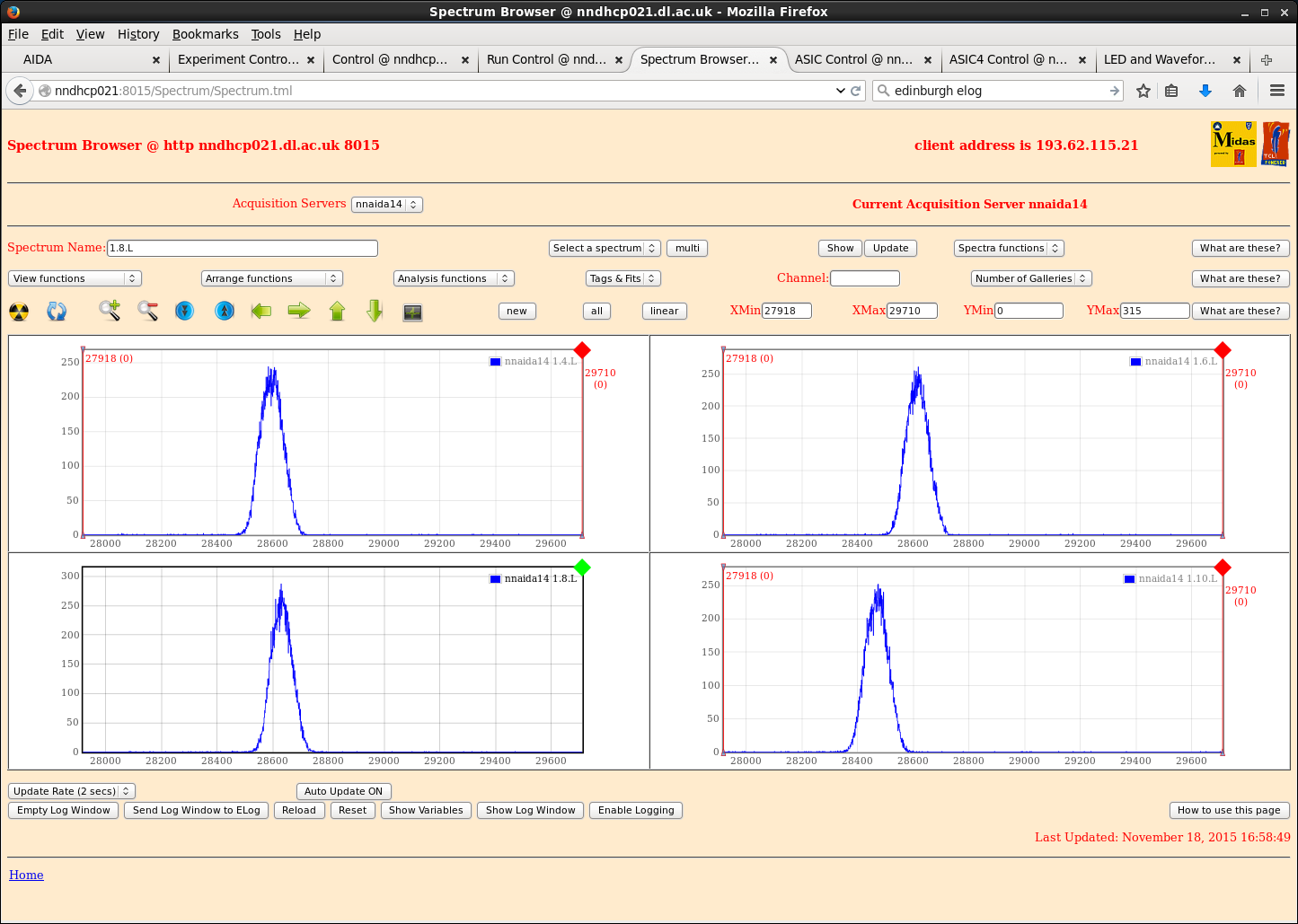
Added ~20cm drain wires to each kapton and connected all at one point on mount screw above nnaida14 adapter PCB connector. Again looked at variation with shaping time.
t_shape (us) || 0.5 | 1.0 | 2.0 | 4.0 | 8.0
Pulser FWHM (ch) || 363 | 354 | 245 | 120 | 85 (nnaida14)
- again, at low shaping times all peaks started out double peaked, but moved closer to Gaussian as t_shape was increased. At 8us, not quite Gaussian, but close.
P-side performance much better than n-side.
- currently drain wires are connected to p-side adapter PCB. Will move these to n-side PCB tomorrow to see if this has any affect. |
| Attachment 1: nnaida11_noJumpers.png
|
|
| Attachment 2: nnaida14_detectorGNDjumper.png
|
|
| Attachment 3: nnaida14_shortDrainWires.png
|
|
| Attachment 4: nnaida14_shortDrainWiresSinglePoint_8us.png
|
|
| Attachment 5: IMG_20151118_164436.jpg
|
|