| ID |
Date |
Author |
Subject |
|
72
|
Sun Oct 9 15:49:41 2016 |
JL Tain et al | Power shutdown |
Due to maintenance operations of the Wako electrical
company there is a risk of power shutdowns on Saturday,
Sunday and Monday from about 8 am to 8 pm.

So we have to stop working on the hardware during
this time |
|
71
|
Sun Oct 9 04:20:47 2016 |
JL Tain et al | Noise |
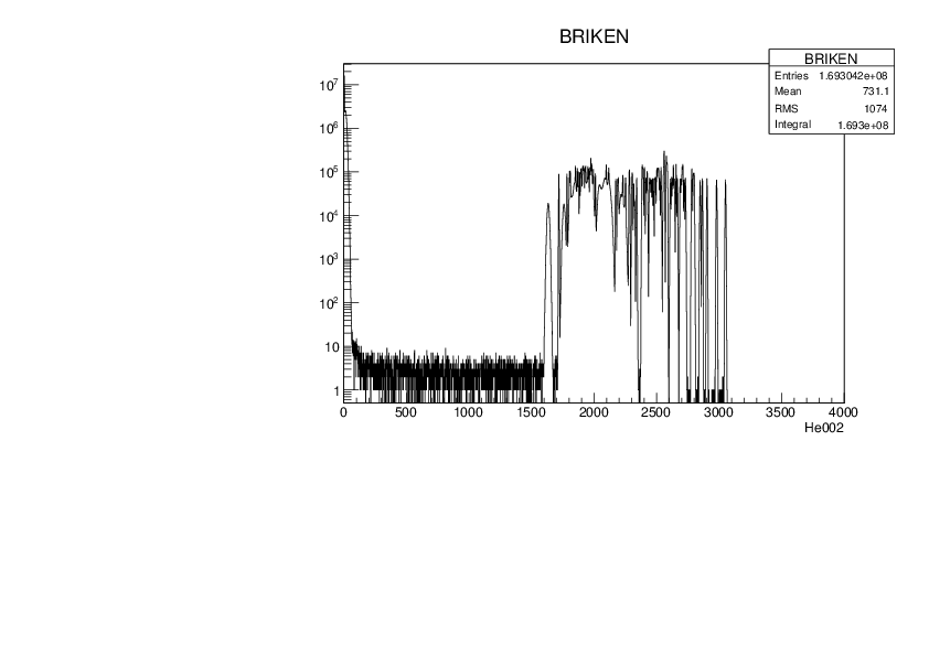
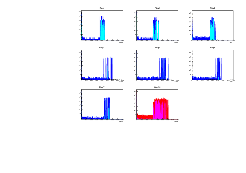
We check for the appearance of spurious signals in the preamplifiers.

We set all HV to zero and run a measurement for several hours.
Start: October 7, 20:00
Stop: October 8, 06:42
File: 161008_0642_noHV.root

De inspection of the different channels do not reveal any
particular problem.

See figure for channels grouped in rings |
| Attachment 1: noHV.pdf
|
|
| Attachment 2: 161008_0642_noHV.pdf
|
|
|
70
|
Sat Oct 8 01:18:51 2016 |
JL Tain et al | DACQ |
We increased the pretrigger delay for ADC5 from 350 to 400 |
|
68
|
Fri Oct 7 10:42:52 2016 |
JL Tain et al | Noise |
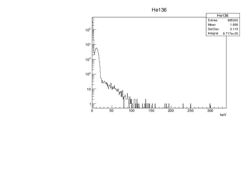
We investigate the effect on the noise in ORNL tubes of using a differential PA.

We connect the tubes in current PA10 (126-140) to one of the new diff PA
and connect the output to converter card #4 which is connected to ADC3 (and ADC4).

First a short run with 252Cf for setting the right parameters and the calibration
file: 161007_1743_252Cf_ORNL_diffPreamp.root

Then we make a background run
file: 161007_1743_bck_ORNL_diffPreamp.root

As can be seen in the figure the effect of the differential preamp is to
compress the noise down to 100keV, becoming more similar to
the situation of the RIKEN tubes.

Thus it will be beneficial to use Diff PA. However as we can only setup one
because we have only one spare Diff-Unip converter card, we decided not to
use it as the impact will be very low and implies a lot of changes.
However one must remember that since we are always going to require coincidence
with betas during the measurement this noise should have no effet. |
| Attachment 1: ORNL-DiffPreamp.pdf
|
|
|
67
|
Fri Oct 7 08:35:15 2016 |
JL Tain et al | Noise |
Low amplitude noise component.

The figure shows the composition of the low amplitude noise
which depends on the tube and type of preamplifier used.

Bkack: He020 (RIKEN-Diff)
Red: He044 (UPC-Diff)
Green: He057 (UPC-Unip)
Blue: He068 (ORNL1-Unip)
Pink: He132 (ORNL2-Unip)

(all the tubes of the same type and preamp type behave alike)

We can see up to three different structures.
The noise in the ORNL tubes extends to higher energies (200keV)
and are the cause for the overlap of noise with neutron signals,
but other wise the shape is similar to RIKEN tubes.
The noise for UPC above 50kev is quite small.
One can also see a small difference between differential and unipolar PA
in the case of UPC tubes (red and green) |
| Attachment 1: noiseDifferentTubes2.pdf
|

|
|
66
|
Fri Oct 7 08:09:47 2016 |
JLTain et al | Background |
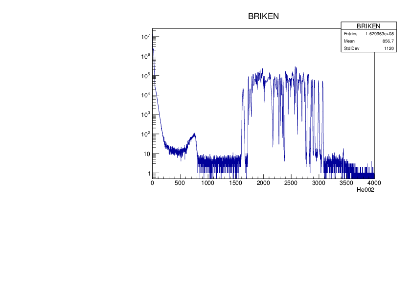
Background measurement overnight
Start: Oct-6 2242 Stop: Oct-7 10:45

file: 161007_1045_bck.root

See attached figure.
We see that low amplitude noise overlaps with the neutron spectrum.
We also see the grass-like background which extends all the way
up to the ADC range. |
| Attachment 1: Bckg-1st.pdf
|
|
| Attachment 2: 161007_1045_bck.pdf
|

|
|
65
|
Thu Oct 6 14:50:30 2016 |
JL Tain, A Tolosa, A Tarifeno,... | 252Cf |
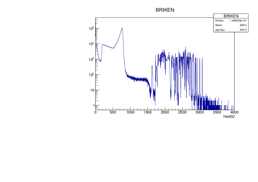
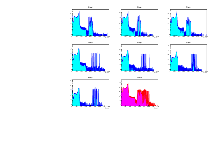
First measurement with 252Cf source to check the calibration.
AIDA was in place so the source was at the right height
but displaced about 10cm from the center.

We use the last configuation file used in July:
160718Conf_BrikenFull_cal5.xlsx

tmeas=25min
file: 161006_2235_252Cf.root

The noise is rather small.
The calibration of July is nearly OK! |
| Attachment 1: 252Cf-1st.pdf
|
|
| Attachment 2: 161006_2235_252Cf.pdf
|
|
|
64
|
Thu Oct 6 14:43:47 2016 |
JL Tain, A Tarifeno, A Tolosa, J Agramunt, N Brewer, S Go, ... | Electronics |
We mount back all preamplifiers
Initially we used all the PA coming from US, the repaired and the new ones.
There was an issue with the new ones (strong noise and cross talk)
until we realized that the new ones were of differential type
instead of unipolar. We decided to mount all unipolar so we use
the repaired ones plus the ones which were left here and
had some minor problems with discharges.

We decided to change slightly the gain of the pulser signals
because for PA6 to PA10 the amplitude after the preamp was 2.2-2.4V
so it was saturating the ADC.
So we decreased Pulser 1 (RIKEN, ORNL1, ORNL2, CLOVER)
from 690mV to 540mV (NEG) on the scope (50ohm)
and increased Pulser 2 (UPC) from 90mV to 100mV |
|
63
|
Thu Oct 6 02:03:32 2016 |
JL Tain | START |
We started the assembly of BRIKEN and AIDA detectors in their final position
on Tuesday October 4:

Gabor Kiss, Phong Vi, Keishi Matsui, Shunji Nishimura, Shigeru Kubono, PA,
Chris Griffin, Tom Davinson, Nathan Brewster, Shintaro Go, Daniel Stracener,
Ariel Tarifeno, Jorge Agramunt, Alvaro Tolosa, Jose L Tain

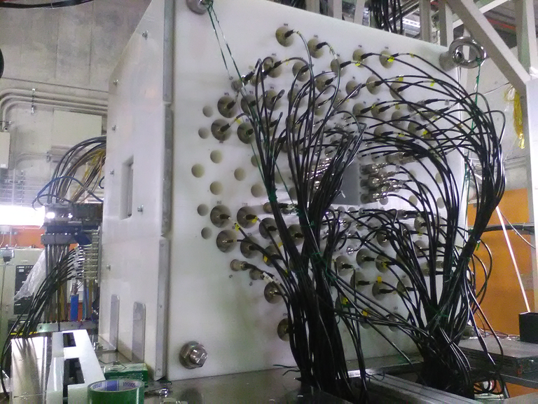
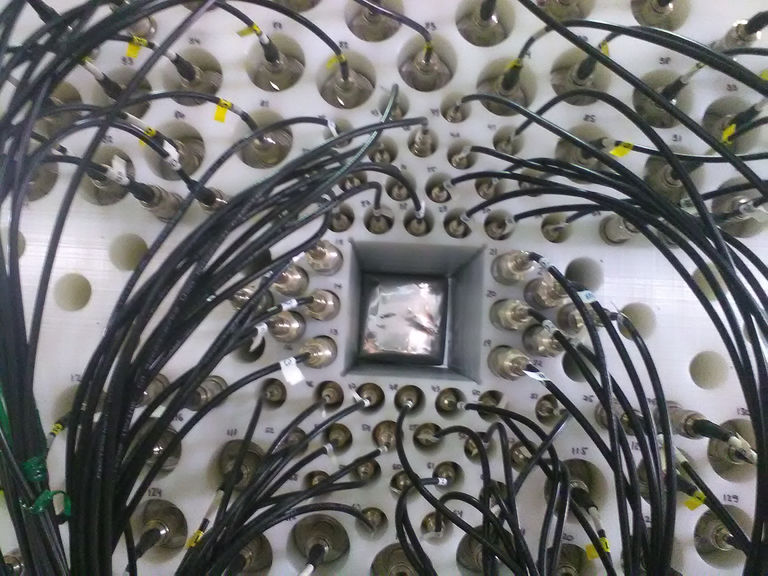
Tubes were removed from BRIKEN. PE matrix lifted with crane.
Table rotated and placed in the final position (front wheels
between forward EURICA rails) by hand. Table leveled (height, angle)
with the help of laser. PE matrix placed back.
AIDA rotated and adjusted to BRIKEN by hand.

See photos |
| Attachment 1: BRIKEN-AIDA.jpg
|

|
| Attachment 2: BRIKENfront.jpg
|
|
| Attachment 3: AIDAback.jpg
|

|
| Attachment 4: AIDAintoBRIKEN.jpg
|

|
| Attachment 5: AIDAnosefront.jpg
|
|
| Attachment 6: AIDA-CLOVERhole.jpg
|

|
|
62
|
Thu Aug 18 23:32:59 2016 |
NT Brewer | New preamps arrived at Oak Ridge and tested working. |
Collaborators,
Attached is a phone photo of example signals from the new preamps with 3 3He tubes connected to a scope. Scope channels 1,2,3 (color y,c,m respectively) are preamp channels 1,2,3 while 4 (green) is open. Trigger is on channel 3, at 500mV/div and other channels are at 500,200,and 20 mV/Div for channels 2,1,4 respectively. Time scale, though glared out should be 10us per div ( although we saw longer rise times as well).
Signals were all good for all channels. Coincident with real signals were other negative signals ~15x (750mV/50mV magenta/green) smaller and with a different shape. No positive signals were observed in any channel.
This picture is representative of the signals of 2 new preamps as well as the functional spare already at UT.
Additionally, the two preamps sent for repair have been received.
NTB, KPR
|
| Attachment 1: IMG_20160818_145801.jpg
|

|
| Attachment 2: IMG_20160803_160430.jpg
|

|
|
Draft
|
Thu Aug 18 22:39:35 2016 |
NT Brewer | New preamps arrived at Oak Ridge and tested working. |
Collaborators,
Attached is a phone photo of example signals from the new preamps with 3 3He tubes connected to a scope. Scope channels 1,2,3 (color y,c,m respectively) are preamp channels 1,2,3 while 4 (green) is open. Trigger is on channel 3, at 500mV/div and other channels are at 500,200,and 20 mV/Div for channels 2,1,4 respectively. Time scale, though glared out should be 10us per div ( although we saw longer rise times as well).
Signals were all good for all channels. Coincident with real signals were other negative signals ~15x (750mV/50mV magenta/green) smaller and with a different shape. No positive signals were observed in any channel.
This picture is representative of the
|
| Attachment 1: IMG_20160818_145801.jpg
|

|
|
60
|
Fri Jul 29 09:52:28 2016 |
Keishi Matsui | accuracy of Cf-252's intensity in RIKEN |
According to the reply from Japan Radioisotope Association, the accuracy of the Cf-252's intensity is +0%/-15%.
( "+0%" is important, because 3.7 MBq is a standard limit for radio-active sources in Japan.) |
| Attachment 1: IMG_9350.JPG
|

|
|
59
|
Fri Jul 22 12:50:29 2016 |
J.L. Tain | END |
20/JUL/2016 20:00
End of the test measurements |
|
58
|
Wed Jul 20 17:21:59 2016 |
J. Agramunt, A. Tolosa | DACQ |
DACQ configuration parameters

The last configuration file used was: 160718Conf_BrikenFull_cal5.xlsx

Most relevant configuration parameters:
3He tubes:
For all channels:
Input: InputRange: 2V, Impedance: 50Ohm
Tigger: Fast filter IntTime: 40, FlatTop: 20

V1A1C1-C16: (RIKEN: PA1,PA2)
Input: Offset: 50000, Polarity: + (POS)
Trigger: GateLength: 800, PreTrigger: 250, Threshold: 2000
Slow Filter: IntTime: 250, FlatTop: 50, Tau: 25000

V1A2C1-C8: (RIKEN: PA2)
Input: Offset: 50000, Polarity: + (POS)
Trigger: GateLength: 800, PreTrigger: 250, Threshold: 2000
Slow Filter: IntTime: 250, FlatTop: 50, Tau: 25000

V1A2C9-C16: (UPC: PA3)
Input: Offset: 50000, Polarity: + (POS)
Trigger: GateLength: 800, PreTrigger: 250, Threshold: 10000
Slow Filter: IntTime: 175, FlatTop: 50, Tau: 25000

V1A3C1-C16: (UPC: PA3,PA4)
Input: Offset: 50000, Polarity: + (POS)
Trigger: GateLength: 800, PreTrigger: 250, Threshold: 10000
Slow Filter: IntTime: 175, FlatTop: 50, Tau: 25000

V1A4C1-C4: (UPC: PA4)
Input: Offset: 50000, Polarity: + (POS)
Trigger: GateLength: 800, PreTrigger: 250, Threshold: 8000
Slow Filter: IntTime: 175, FlatTop: 50, Tau: 25000

V1A4C5-C16: (UPC: PA5)
Input: Offset: 15000, Polarity: - (NEG)
Trigger: GateLength: 1000, PreTrigger: 250, Threshold: 15000
Slow Filter: IntTime: 250, FlatTop: 100, Tau: 25000

V1A5C1-C16: (ORNL1: PA6)
Input: Offset: 15000, Polarity: - (NEG)
Trigger: GateLength: 1000, PreTrigger: 250, Threshold: 3000
Slow Filter: IntTime: 250, FlatTop: 100, Tau: 25000

V1A6C1-C16: (ORNL2: PA7)
Input: Offset: 15000, Polarity: - (NEG)
Trigger: GateLength: 1200, PreTrigger: 350, Threshold: 3000
Slow Filter: IntTime: 350, FlatTop: 100, Tau: 25000

V2A1C1-C8: (ORNL2: PA8) V2A2C1-C8: (ORNL2: PA8)
V2A3C1-C8: (ORNL2: PA9) V2A4C1-C8: (ORNL2: PA9)
V2A5C1-C8: (ORNL2: PA10) V2A6C1-C8: (ORNL2: PA10)
Input: Offset: 48000, Polarity: - (NEG)
Trigger: GateLength: 1000, PreTrigger: 100, Threshold: 200
Slow Filter: IntTime: 350, FlatTop: 100, Tau: 25000

CLOVERS:
Input: InputRange: 2V, Impedance: 50Ohm, Offset: 50000, Polarity: - (NEG)
Trigger: Fast filter IntTime: 20, FlatTop: 20, Threshold: 30
Trigger: GateLength: 750, PreTrigger: 75
Slow Filter: IntTime: 500, FlatTop: 50, Tau: 37000 |
| Attachment 1: 160718Conf_BrikenFull_cal5.xlsx
|
|
57
|
Wed Jul 20 17:18:59 2016 |
J.L. Tain, J. Agramunt, A. Tarifeņo, A. Tolosa, K. Gabor, S. Go, K. Matsui... | Electronics |
Measurement with preamplifiers after drying.

Amplifiers are brought back after ~12h and connected.
Measurement of background for 1hour
Online: 160720_1350_1452_Bkg.root
Listmode: No

There might have been a slight improvement on the PA behaviour
but is not clear.

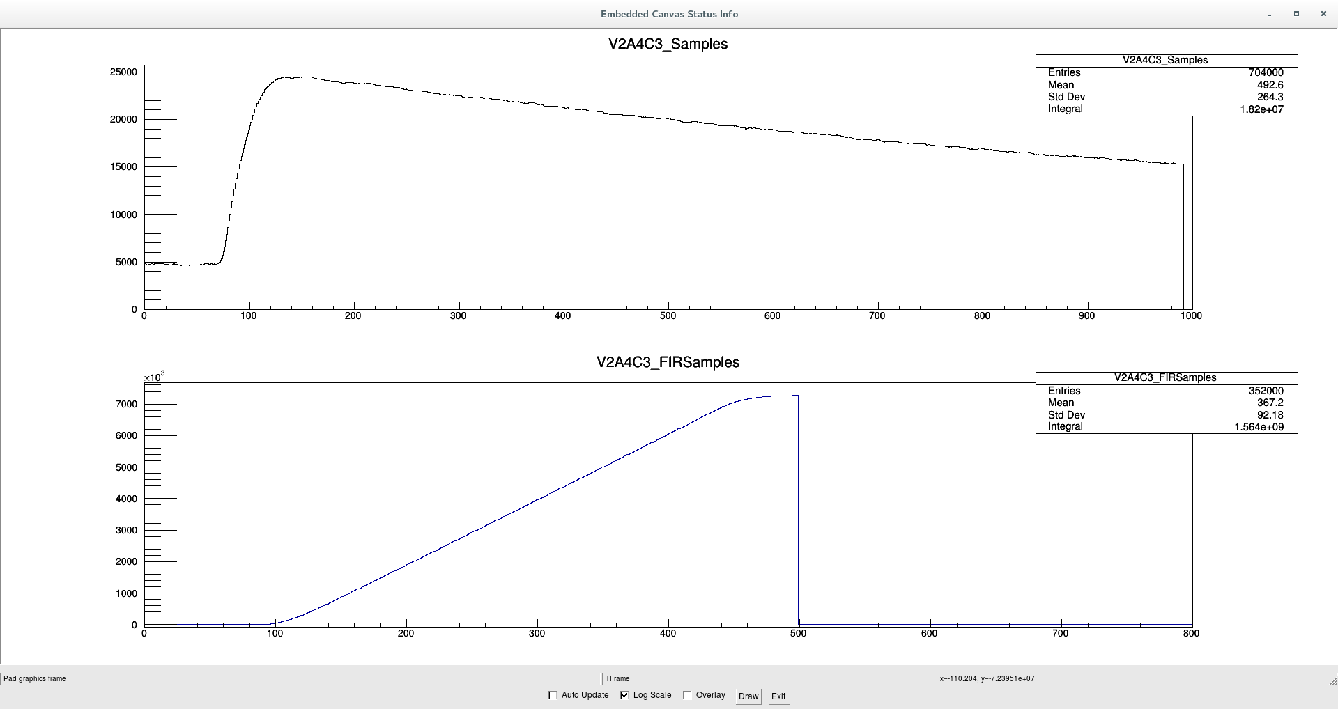
Attached a screen shot of the spectrum

The spurious signals show very little noise superimposed
as can be seen in the attached capture of the sample by the DACQ
but is not so obvious how this can help to veto them. |
| Attachment 1: Bkg-afterPAdrying.png
|

|
| Attachment 2: V2A4C3-SpuriousSignal.png
|
|
|
56
|
Wed Jul 20 17:05:59 2016 |
J.L. Tain, J. Agramunt, A. Tarifeņo, A. Tolosa, ... | Background |
Background measurement with remaining tubes (95) overnight

Listmode: 160719_2343_Bkg_*.dlt, Run: 031-044
Online: 160719_2343_1030_Bkg.root

Unfortunately the 252Cf source remained ind the hall (shielded and far away but still)

Screen shot of neutron spectrum |
| Attachment 1: Bkg-with95tubes.png
|

|
|
55
|
Wed Jul 20 16:55:48 2016 |
K.Gabor, K. Matsui, A. Tarifeņo | Electronic |
Drying of preamplifiers

PA8, PA9 and PA10 are removed and brought to a dryer box
to stay overnight and see if the situation with spurious signals
improves as suggested by Mesytec.
Extra drying in the morning with a hair dryer. |
|
54
|
Wed Jul 20 16:50:12 2016 |
J.L. Tain, J. Agramunt, A. Tarifeņo, A. Tolosa, S. Go... | 252Cf |
Measurement of the 252Cf source at the central position

Efficiency and neutron-gamma correlations

Listmode: 160719_2233_252Cf_XX.dlt, Run: 029-030
Online: 160719_2233_252Cf_029_030.root |
|
53
|
Wed Jul 20 16:40:57 2016 |
S. Go, J.Agramunt, A.Tolosa, J.L. Tain,... | CLOVER |
Calibration and resolution check

CLOVER detectors were calibrated in energy with 60Co and 137Cs
60Co source: 2530, 8.81E4Bq (16/03/2010)
137Cs source: CD393 (box), ?
Sources were placed at the center

Resolution(FWHM@1333keV):
G7 Blue:2.67keV
G7 Green: 2.84keV
G7 Red: 2.77keV
G7 Black: 2.64keV
D4 Blue: 3.60keV
D4 Green: 3.35keV
D4 Red: 3.41keV
D4 Black: 4.85keV (!?)

Efficiency calibration with 152Eu
Source place at the center
Source: 272 (09-7011), 1.062E4Bq (error:1.9%)@16/03/2010
File: 160719_2201_152Eu_028.dlt
Online: 160719_2201_152Eu_028.root

Attached 152Eu spectrum |
| Attachment 1: 152Eu.png
|

|
|
52
|
Wed Jul 20 16:12:58 2016 |
S. Go, ... | CLOVER |
Mounting of the CLOVER detectors in position

CLOVER G7: right of beam
CLOVER D4: left of beam

G7 crystals:
Beam ->
Back view:
Red   Blue
Green Black

D4 crystals:
Beam ->
Front view:
Red Green
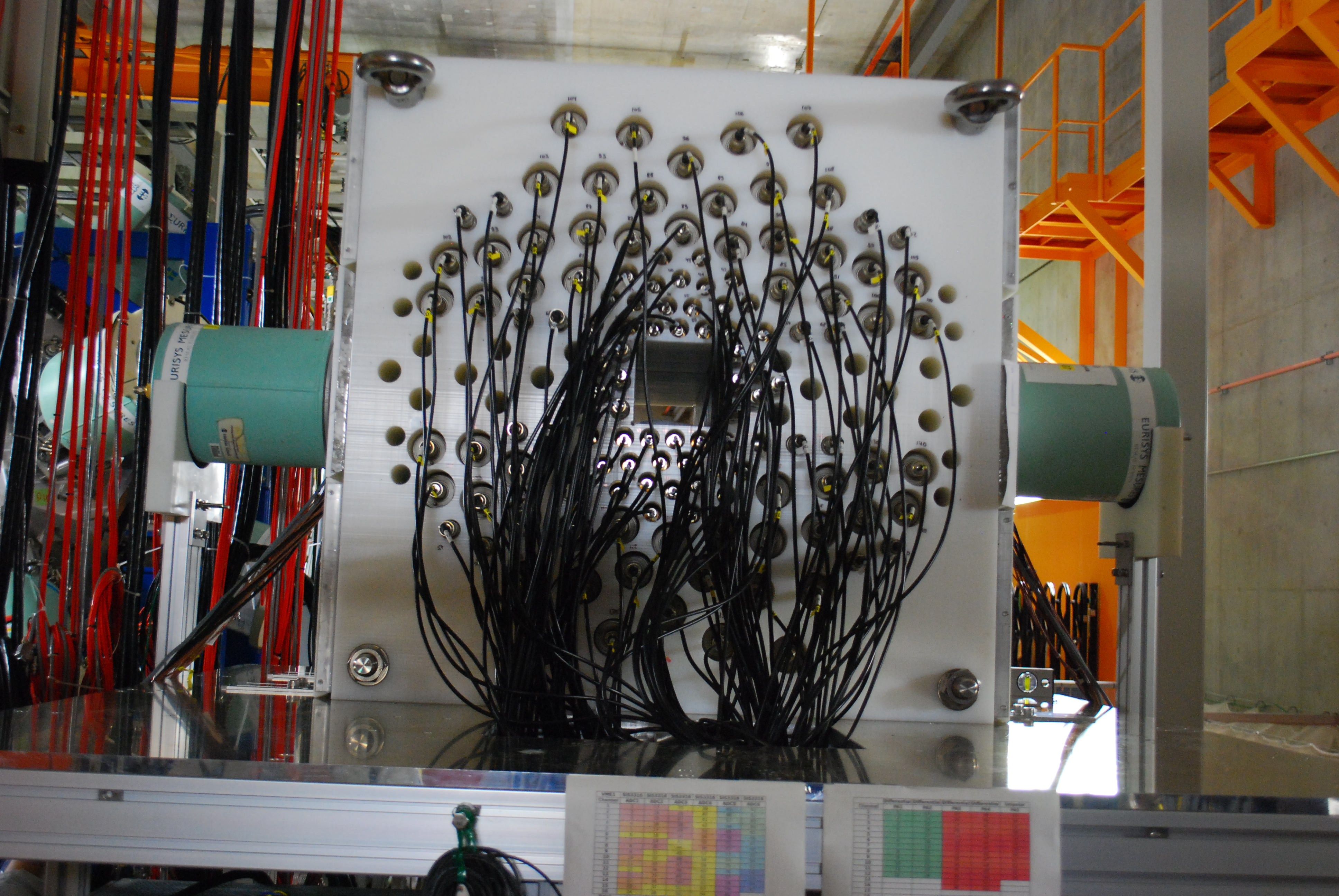
Blue Black

Photos of the arrangement with COVER detectors attached |
| Attachment 1: DSC_2522.JPG
|
|
| Attachment 2: DSC_2523.JPG
|

|
| Attachment 3: DSC_2524.JPG
|

|