| ID |
Date |
Author |
Subject |
|
41
|
Tue Jul 19 03:19:34 2016 |
A. Tarifeņo, I. Dillman, J. Agramunt, A. Tolosa, J.L. Tain... | Electronics |
Preamplifier and signal cable testing

We check all signal cables,the flat cable connector to BNC
from ORNL/UTK and they are OK.

While checking the preamplifiers (PA) we realized that on the oscilloscope
some of the channels shown pulses without a load when HV is on.
After some checks, we come to the conclusion that is a kind of discharge
on the HV part of the preamp (which appears as positive pulse or negative pulses)
and induce pulses of opposite sign in one or mos neighbouring channels.
After systematically investigating them in the scope, we plug them in the DACQ
to record the spectra. For this we include an additional digitizer SIS3316
to connect al1 channel preamps
PA1(D):UPC:SN-0808223 -> V1A1
PA2(D):GSI:SN-1112572 -> V1A2
PA3(D):UPC:SN-0310315 -> V1A3
PA4(D):UPC:SN-0808220 -> V1A4
PA5(U):UTK: ? -> V1A5
PA6(U):UTK:SN-0808218 -> V1A6
PA7(U):UTK:SN-0713586 -> V1A7
PA8(U):UTK:SN-0808221 -> V2A1, V2A2
PA9(U):UTK:SN-0808215 -> V2A3, V2A4
PA10(U):UTK:SN-0808217 -> V2A5, V2A6

We measure first with a tube of each type connected to Ch#1 of each PA
to adjust parameters of digitizers and range
List-mode: 160717_preampCheck_000.dlt
On-line: 160717_preampCheck.root

Then we remove the tube from Ch#1 to see the effect in this channel:
List-mode: 160717_preampCheck_noTubes_001.dlt
On-line: 160717_preampCheck_noTubes.root

We attach screenshots for both as compressed files (.zip)
and the root files |
| Attachment 1: preampCheck.zip
|
| Attachment 2: noTubeCh1.zip
|
| Attachment 3: 160717_preampCheck.root
|
| Attachment 4: 160717_preampCheck_noTubes.root
|
|
42
|
Tue Jul 19 04:09:32 2016 |
JL Tain A Tolosa R. Caballero A. Tarifeņo J. Agramunt | Last tube fit in the matrix!!! |
The photo of great moment |
| Attachment 1: DSC_2478.JPG
|

|
|
43
|
Tue Jul 19 04:34:57 2016 |
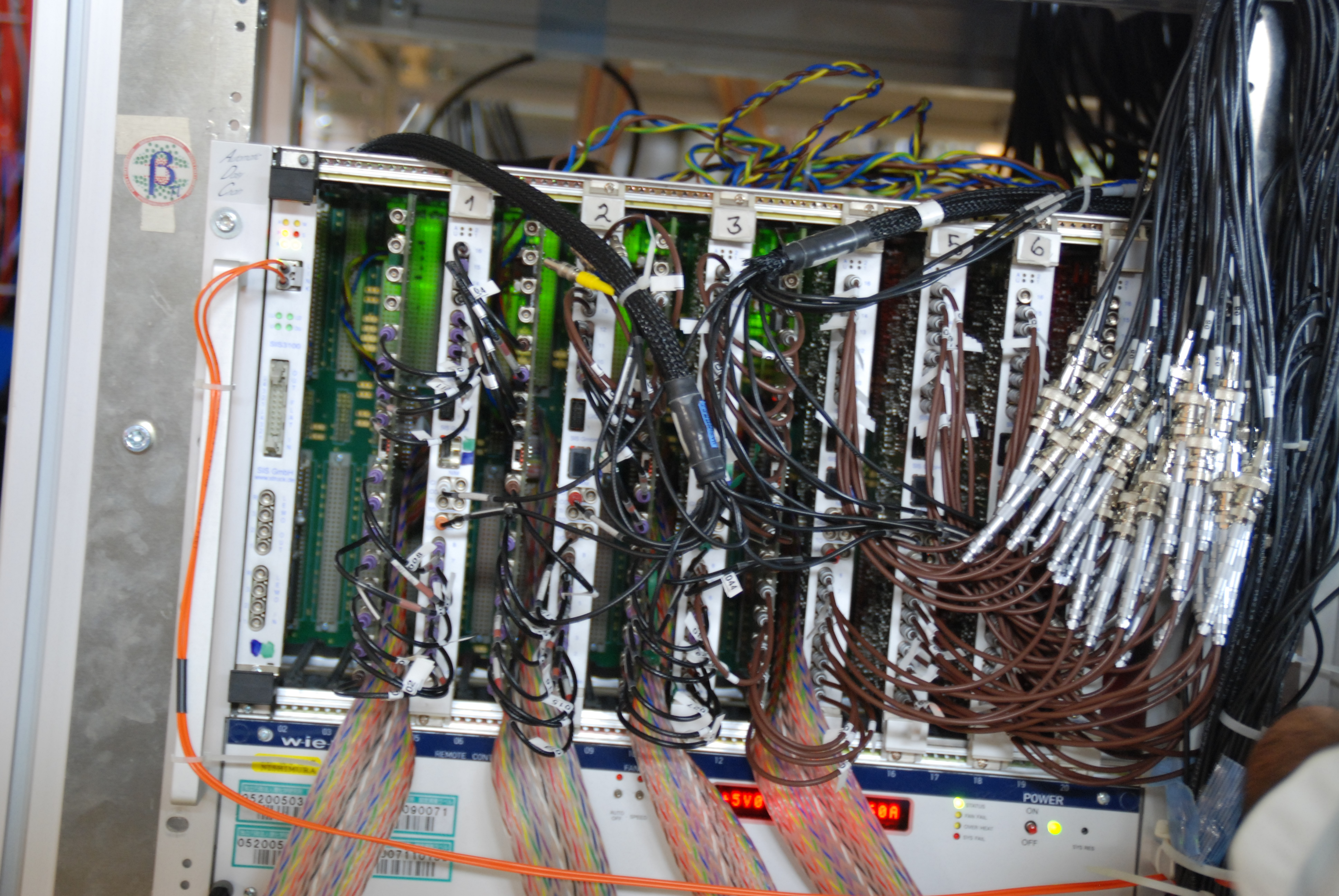
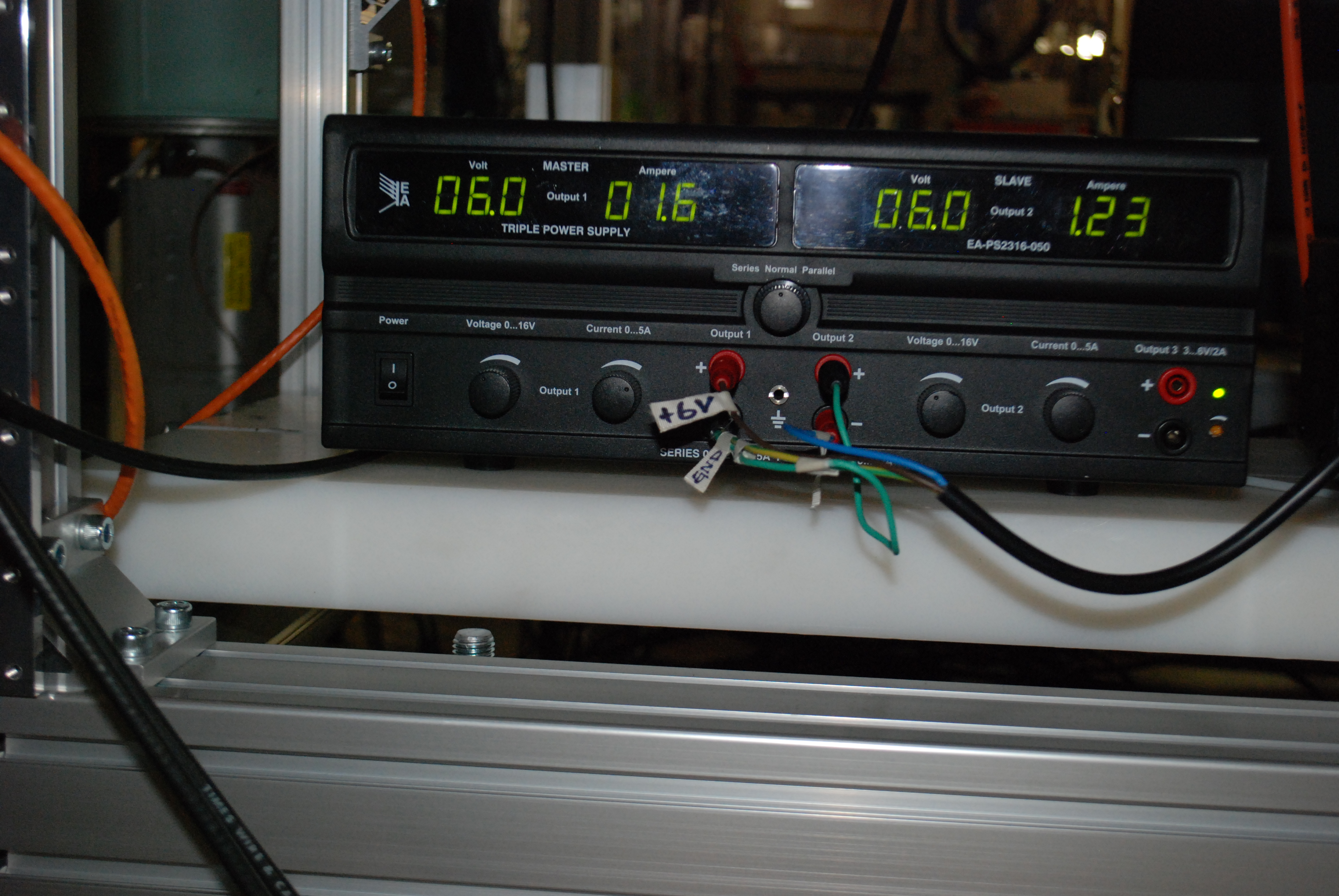
JL Tain A Tolosa R. Caballero A. Tarifeņo J. Agramunt | Photos of the electronics |
Racks, crates, rear part of the preamps and matrix with all tubes. |
| Attachment 1: DSC_0034.JPG
|

|
| Attachment 2: DSC_0022.JPG
|
|
| Attachment 3: DSC_0016.JPG
|

|
| Attachment 4: DSC_2483.JPG
|

|
| Attachment 5: DSC_2497.JPG
|

|
| Attachment 6: DSC_2511.JPG
|
|
| Attachment 7: DSC_2513.JPG
|

|
| Attachment 8: DSC_2514.JPG
|

|
| Attachment 9: DSC_2526.JPG
|

|
|
44
|
Tue Jul 19 11:54:03 2016 |
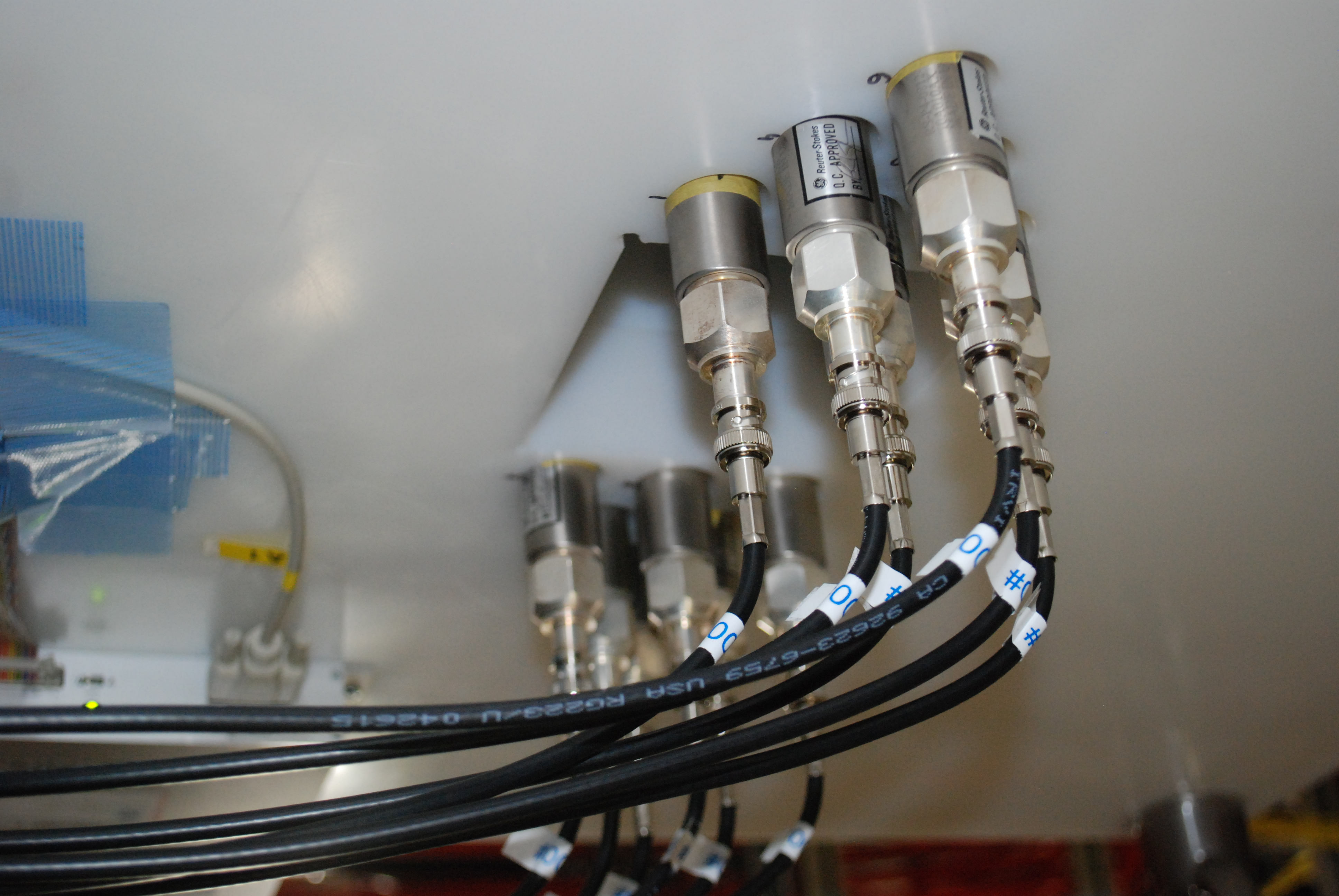
JL Tain A Tolosa R. Caballero A. Tarifeņo J. Agramunt | Photos of the AIDA insertion hole with the 3He tubes |
RIKEN tubes on the AIDA side with the SHV right angle connector will protrude
by ~95mm in the HYBRID configuration (with CLOVERS).
In the current AIDA DSSD configuration there are six detectors occupying 45-50mm
at a distance to center of the stack from the black plastic support of ~430mm.
The hole for the CLOVER is 110mm. The center of the hole is at 375mm from the
PE end.
This means that the center of the current stack is only ~15mm beyond the PE
in the CLOVER hole, so 1 or 2 of the DSSD will be partially shadowed
from the CLOVER detectors.
(This do not represent any problem from the neutron detector point of view) |
| Attachment 1: DSC_2520.JPG
|

|
| Attachment 2: DSC_2517.JPG
|
|
| Attachment 3: DSC_2515.JPG
|

|
|
45
|
Tue Jul 19 13:47:55 2016 |
A. Tarifeņo-Saldivia | Neutron efficiency - Scanning on Z preliminary result |
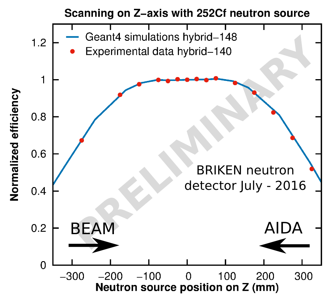
We have carried out a scanning of the neutron efficiency with respect to the position along the Z-axis (AIDA and BEAM hole) of a 252Cf neutron source. A preliminary analysis is presented based on data from the online. A plot with the comparison of the simulations and experimental data is attached. The experimental results are in good agreement with the GEANT4 simulations of the studies for design of the neutron detector. The simulations for the design of the hybrid mode were calculated using 148 3He counters. The version of the hybrid detector assembled during the current campaign (July-2016) is using 140 3He counters. The missing counters correspond to tubes located on the outer part of PE, thus the effect of these counters on the total neutron efficiency is minimal.
|
| Attachment 1: Preliminar_Zscaning_BRIKEN_PremLabel_vsmall.png
|
|
|
46
|
Wed Jul 20 08:58:13 2016 |
J.L. Tain, I.Dillman, R. Caballero, J. Agramunt, A. Tarifeņo, A. Tolosa, ... | Electronics |
Distribution of connections of tubes in preamplifiers and digitizers


Because of the need to use 10 PAs instead of 9 PAs we had to redistribute
the signal connections. Now:
PA1(RIKEN), PA2(RIKEN), PA3(UPC), PA4(UPC), PA5(UPC) -> V1A1-V1A4
PA6(ORNL1) -> V1A5
PA7(ORNL2) -> V1A6
PA8(ORNL2) -> V2A1,V2A2
PA9(ORNL2) -> V2A3,V2A4
PA10(ORNL2) -> V2A5,V2A6

So V1A1 to V1A4 contain now signals from 2 PAs.
We also redistributed the tubes within the PAs
We also changed the numbering or RIKEN Tubes. Tube 1 to 12 are now
those on the AIDA side (PA1 attached to the PE block)

A figure showing the distribution of tubes an numbering is included.
Tube 1 is behind tube 19 and so forth.

Attached also is an excel file with tube-channel distribution |
| Attachment 1: TubeDistribution-new.xlsx
|
| Attachment 2: TubeDistribution-new.pdf
|

|
|
47
|
Wed Jul 20 11:16:18 2016 |
J.L. Tain | Electronics |
Pulser settings

We use two pulsers, Pulser1 for RIKEN, ORNL1 and ORNL2 tubes (7 PA)
and Pulser2 for UPC tubes due to the different gains (3 PA)

10HzClock->G&DG->Pulser->LinearFI/FO

Pulser1: BNC BH-1: trise=1us, tfall=1ms, amp=670mV(scope), NEG
Pulser2: BNC PB-5: tfall=1ms, amp=0.180mV(setting), 90mV(scope), NEG

Later on we found out that Pulser1 is compatible also for
the CLOVER detectors (8PA). This will require an additional LinearFI/FO |
|
48
|
Wed Jul 20 11:40:00 2016 |
J.L. Tain, J. Agramunt, R. Baeturia, A. Tarifeņo, A. Tolosa, ... | 252Cf |
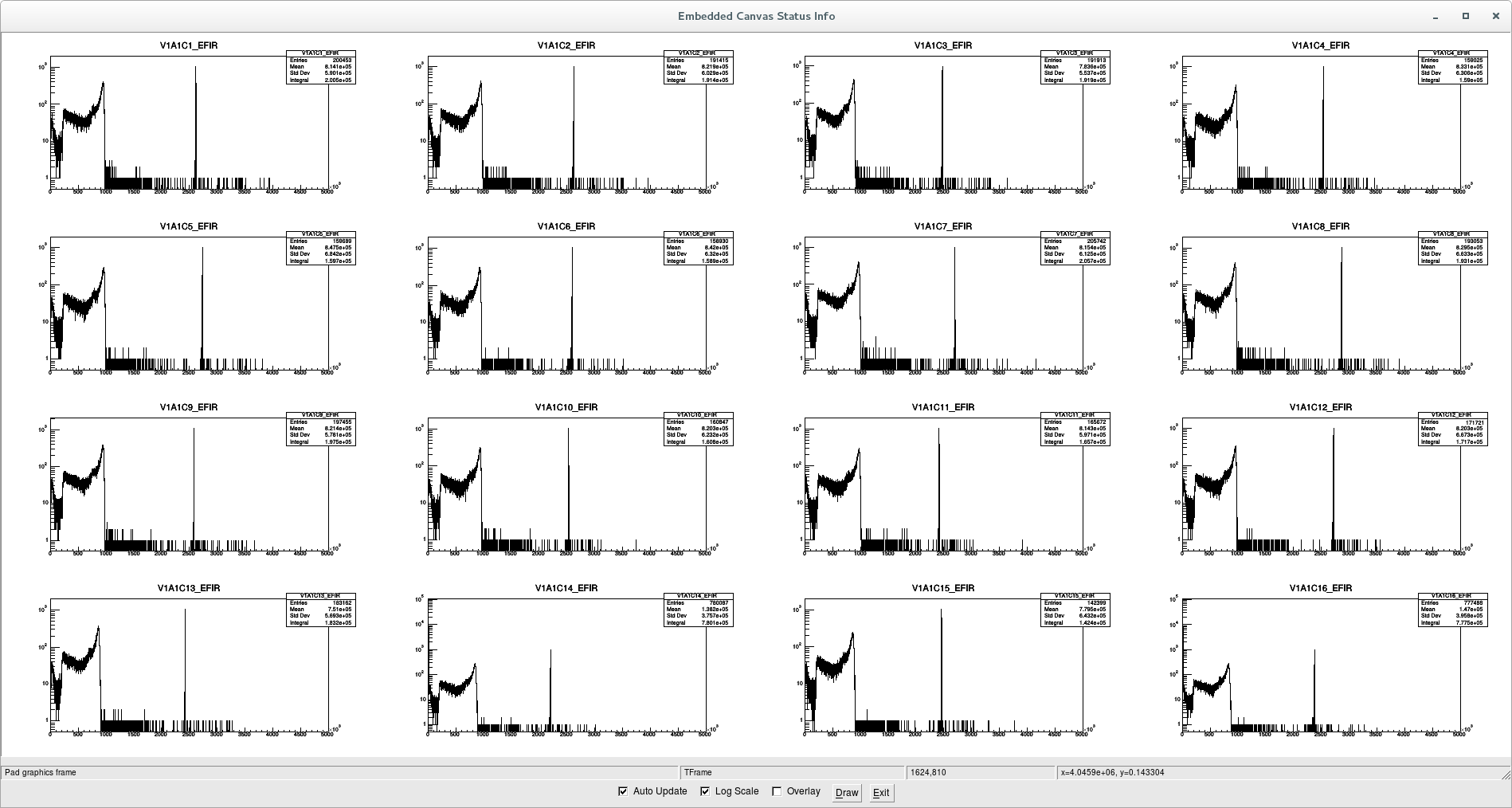
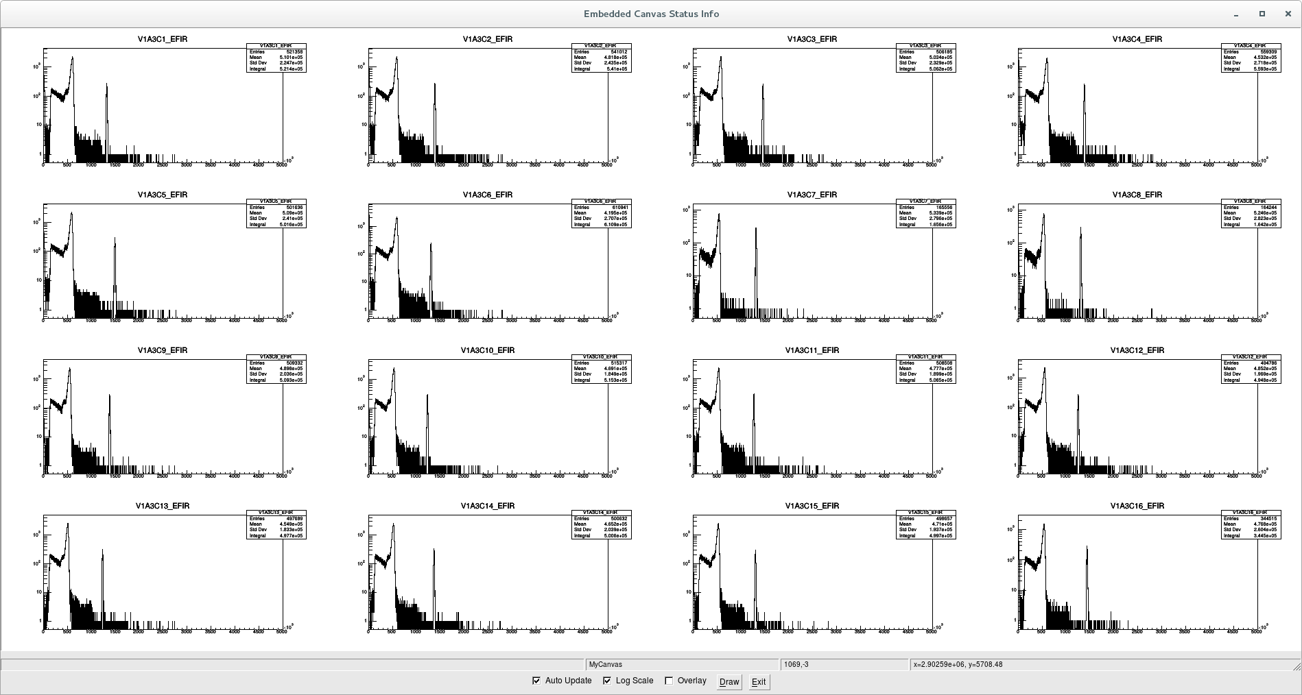
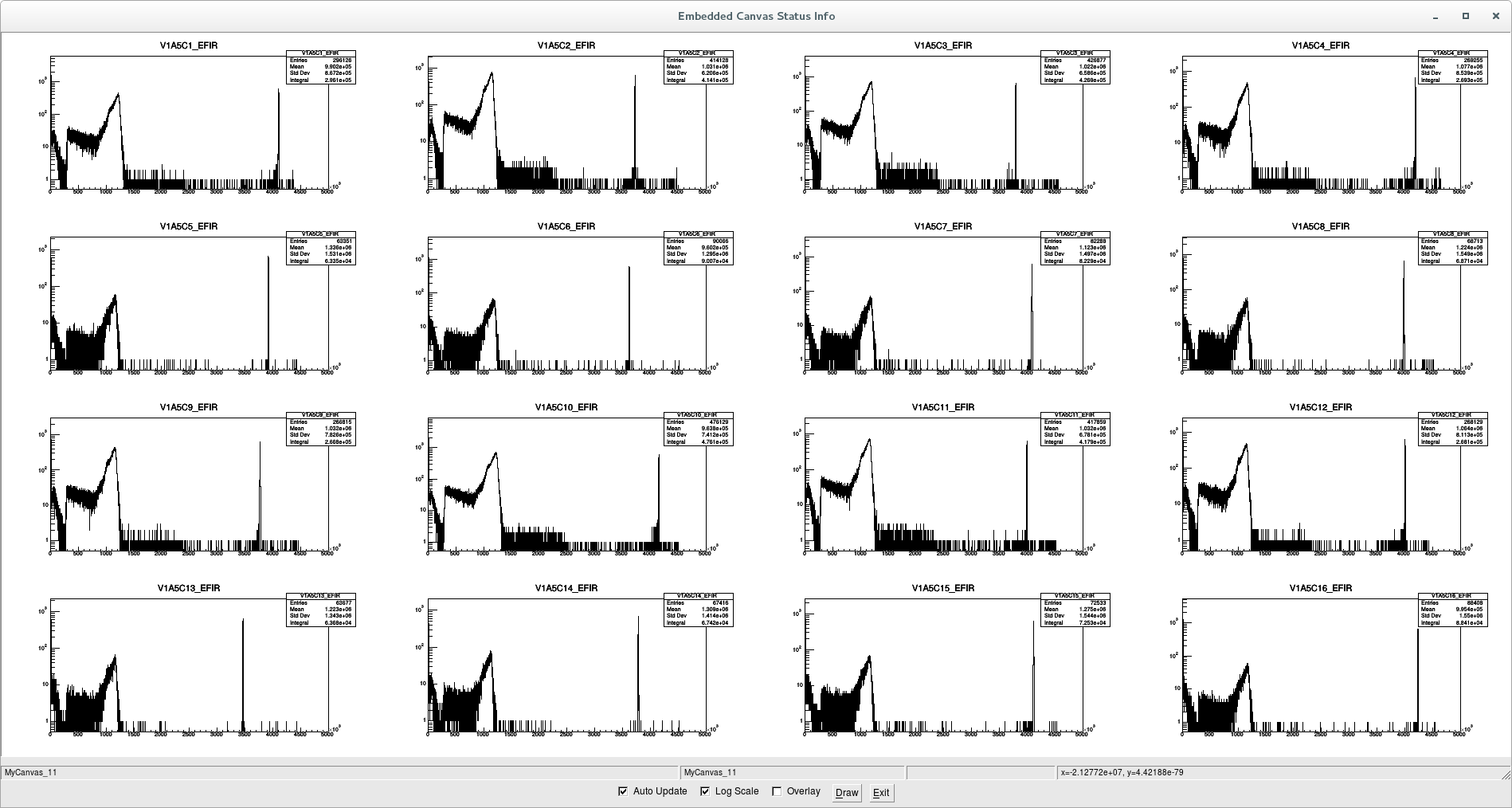
First measurement with full 140 tube version
of the BRIKEN neutron detector

Directory: /data/160716Test01/
Configuration: 160718Conf_BrikenFull.xlsx
File: 160718_FullBrikenFirstData_252Cf_002.dlt
Online: 160718_FullBrikenFirstData_252Cf.root

All tubes and channels working!

Sample of screenshots included. |
| Attachment 1: RIKEN-252Cf-V1A1.png
|
|
| Attachment 2: UPC-252Cf-V1A3.png
|
|
| Attachment 3: ORNL1-252Cf-V1A5.png
|
|
| Attachment 4: ORNL2-252Cf-V1A6.png
|

|
|
49
|
Wed Jul 20 11:49:00 2016 |
J.L. Tain, J. Agramunt, R. Baeturia, A. Tarifeņo, A. Tolosa, ... | Background |
18/07/2016
First background measurement overnight.


START: 23:37
File: 160718_FullBrikenFirstData_bkg_*.dlt Run:003-006
Online: 160718_FullBrikenFirstData_bkg.root

Attached screenshots of raw data for every digitizer.

The problem of some of the PA is visible in the background
spectra.

In addition one can see in some of the channels signals
distributed over all the region up to the pulser and beyond.
This we found to be related to a too low threshold
but can be eliminated with a better adjustment. |
| Attachment 1: 160718_FullBrikenFirstData_bkg.zip
|
|
50
|
Wed Jul 20 12:00:15 2016 |
J.L. Tain, J. Agramunt, A. Tarifeņo, A. Tolosa, ... | 252Cf |
Measurement with the source at the center

Listmode: 160719_BRIKEN_252Cf_009.dlt
Online: 160719_BRIKEN_252Cf.root

BRIKEN: 1.03697E7
Pulser: 5985

Rate: 17326 n/s |
|
51
|
Wed Jul 20 16:07:58 2016 |
A.Tarifeņo, J.L. Tain, J. Agramunt, A. Tolosa, ... | 252Cf |
19/Jul/2016
Scanning of the efficiency as a function of longitudinal position

File:160719_BRIKEN_252Cf_XXmm_*.dlt
Online:160719_BRIKEN_252Cf_XXmm.root
Run: 011-025
Distances: -275,-175,-125,-75,-50.-25,+25,+50,+75,+125,+175,+225,+275,+375mm |
|
52
|
Wed Jul 20 16:12:58 2016 |
S. Go, ... | CLOVER |
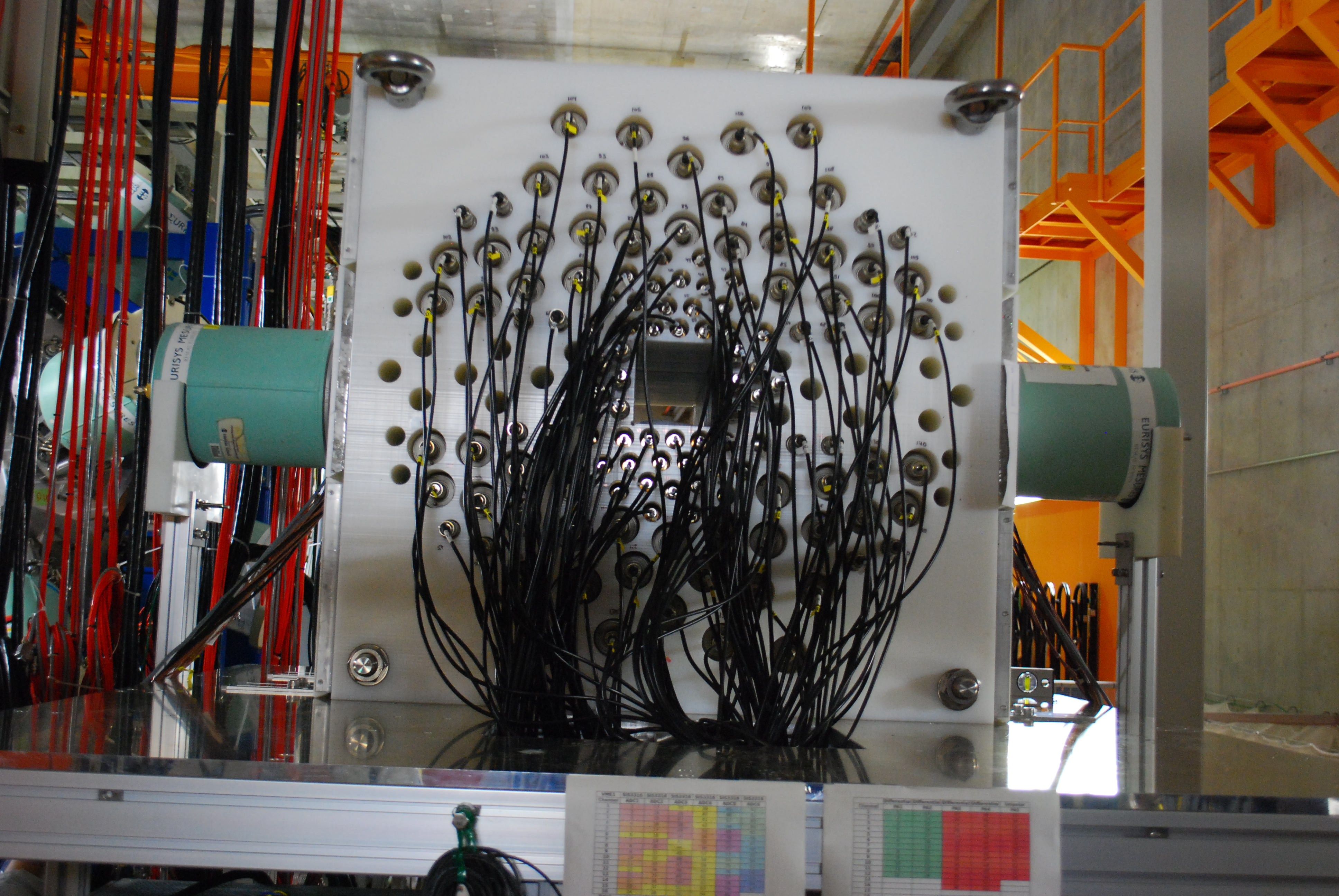
Mounting of the CLOVER detectors in position

CLOVER G7: right of beam
CLOVER D4: left of beam

G7 crystals:
Beam ->
Back view:
Red   Blue
Green Black

D4 crystals:
Beam ->
Front view:
Red Green
Blue Black

Photos of the arrangement with COVER detectors attached |
| Attachment 1: DSC_2522.JPG
|
|
| Attachment 2: DSC_2523.JPG
|

|
| Attachment 3: DSC_2524.JPG
|

|
|
53
|
Wed Jul 20 16:40:57 2016 |
S. Go, J.Agramunt, A.Tolosa, J.L. Tain,... | CLOVER |
Calibration and resolution check

CLOVER detectors were calibrated in energy with 60Co and 137Cs
60Co source: 2530, 8.81E4Bq (16/03/2010)
137Cs source: CD393 (box), ?
Sources were placed at the center

Resolution(FWHM@1333keV):
G7 Blue:2.67keV
G7 Green: 2.84keV
G7 Red: 2.77keV
G7 Black: 2.64keV
D4 Blue: 3.60keV
D4 Green: 3.35keV
D4 Red: 3.41keV
D4 Black: 4.85keV (!?)

Efficiency calibration with 152Eu
Source place at the center
Source: 272 (09-7011), 1.062E4Bq (error:1.9%)@16/03/2010
File: 160719_2201_152Eu_028.dlt
Online: 160719_2201_152Eu_028.root

Attached 152Eu spectrum |
| Attachment 1: 152Eu.png
|

|
|
54
|
Wed Jul 20 16:50:12 2016 |
J.L. Tain, J. Agramunt, A. Tarifeņo, A. Tolosa, S. Go... | 252Cf |
Measurement of the 252Cf source at the central position

Efficiency and neutron-gamma correlations

Listmode: 160719_2233_252Cf_XX.dlt, Run: 029-030
Online: 160719_2233_252Cf_029_030.root |
|
55
|
Wed Jul 20 16:55:48 2016 |
K.Gabor, K. Matsui, A. Tarifeņo | Electronic |
Drying of preamplifiers

PA8, PA9 and PA10 are removed and brought to a dryer box
to stay overnight and see if the situation with spurious signals
improves as suggested by Mesytec.
Extra drying in the morning with a hair dryer. |
|
56
|
Wed Jul 20 17:05:59 2016 |
J.L. Tain, J. Agramunt, A. Tarifeņo, A. Tolosa, ... | Background |
Background measurement with remaining tubes (95) overnight

Listmode: 160719_2343_Bkg_*.dlt, Run: 031-044
Online: 160719_2343_1030_Bkg.root

Unfortunately the 252Cf source remained ind the hall (shielded and far away but still)

Screen shot of neutron spectrum |
| Attachment 1: Bkg-with95tubes.png
|

|
|
57
|
Wed Jul 20 17:18:59 2016 |
J.L. Tain, J. Agramunt, A. Tarifeņo, A. Tolosa, K. Gabor, S. Go, K. Matsui... | Electronics |
Measurement with preamplifiers after drying.

Amplifiers are brought back after ~12h and connected.
Measurement of background for 1hour
Online: 160720_1350_1452_Bkg.root
Listmode: No

There might have been a slight improvement on the PA behaviour
but is not clear.

Attached a screen shot of the spectrum

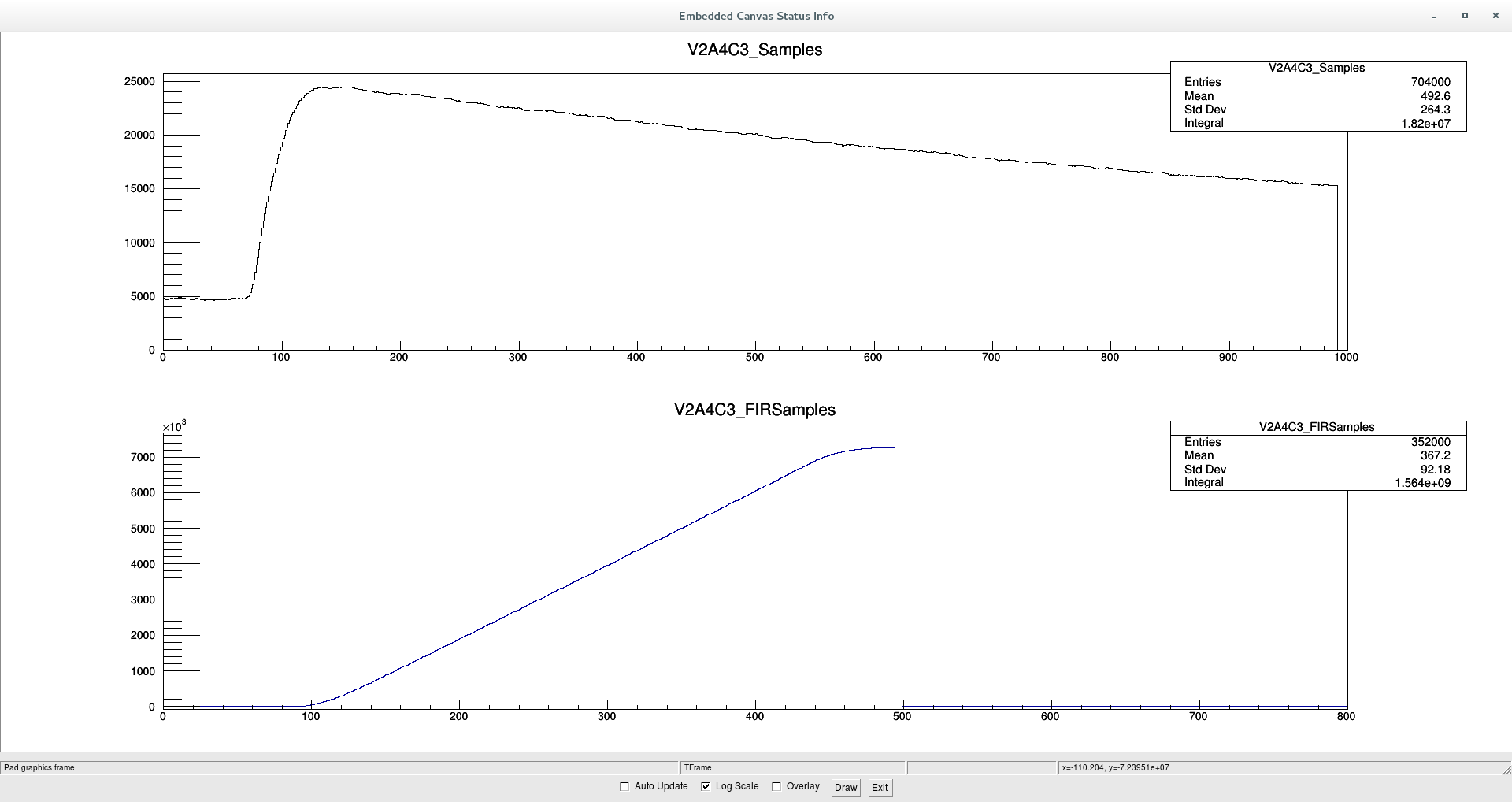
The spurious signals show very little noise superimposed
as can be seen in the attached capture of the sample by the DACQ
but is not so obvious how this can help to veto them. |
| Attachment 1: Bkg-afterPAdrying.png
|

|
| Attachment 2: V2A4C3-SpuriousSignal.png
|
|
|
58
|
Wed Jul 20 17:21:59 2016 |
J. Agramunt, A. Tolosa | DACQ |
DACQ configuration parameters

The last configuration file used was: 160718Conf_BrikenFull_cal5.xlsx

Most relevant configuration parameters:
3He tubes:
For all channels:
Input: InputRange: 2V, Impedance: 50Ohm
Tigger: Fast filter IntTime: 40, FlatTop: 20

V1A1C1-C16: (RIKEN: PA1,PA2)
Input: Offset: 50000, Polarity: + (POS)
Trigger: GateLength: 800, PreTrigger: 250, Threshold: 2000
Slow Filter: IntTime: 250, FlatTop: 50, Tau: 25000

V1A2C1-C8: (RIKEN: PA2)
Input: Offset: 50000, Polarity: + (POS)
Trigger: GateLength: 800, PreTrigger: 250, Threshold: 2000
Slow Filter: IntTime: 250, FlatTop: 50, Tau: 25000

V1A2C9-C16: (UPC: PA3)
Input: Offset: 50000, Polarity: + (POS)
Trigger: GateLength: 800, PreTrigger: 250, Threshold: 10000
Slow Filter: IntTime: 175, FlatTop: 50, Tau: 25000

V1A3C1-C16: (UPC: PA3,PA4)
Input: Offset: 50000, Polarity: + (POS)
Trigger: GateLength: 800, PreTrigger: 250, Threshold: 10000
Slow Filter: IntTime: 175, FlatTop: 50, Tau: 25000

V1A4C1-C4: (UPC: PA4)
Input: Offset: 50000, Polarity: + (POS)
Trigger: GateLength: 800, PreTrigger: 250, Threshold: 8000
Slow Filter: IntTime: 175, FlatTop: 50, Tau: 25000

V1A4C5-C16: (UPC: PA5)
Input: Offset: 15000, Polarity: - (NEG)
Trigger: GateLength: 1000, PreTrigger: 250, Threshold: 15000
Slow Filter: IntTime: 250, FlatTop: 100, Tau: 25000

V1A5C1-C16: (ORNL1: PA6)
Input: Offset: 15000, Polarity: - (NEG)
Trigger: GateLength: 1000, PreTrigger: 250, Threshold: 3000
Slow Filter: IntTime: 250, FlatTop: 100, Tau: 25000

V1A6C1-C16: (ORNL2: PA7)
Input: Offset: 15000, Polarity: - (NEG)
Trigger: GateLength: 1200, PreTrigger: 350, Threshold: 3000
Slow Filter: IntTime: 350, FlatTop: 100, Tau: 25000

V2A1C1-C8: (ORNL2: PA8) V2A2C1-C8: (ORNL2: PA8)
V2A3C1-C8: (ORNL2: PA9) V2A4C1-C8: (ORNL2: PA9)
V2A5C1-C8: (ORNL2: PA10) V2A6C1-C8: (ORNL2: PA10)
Input: Offset: 48000, Polarity: - (NEG)
Trigger: GateLength: 1000, PreTrigger: 100, Threshold: 200
Slow Filter: IntTime: 350, FlatTop: 100, Tau: 25000

CLOVERS:
Input: InputRange: 2V, Impedance: 50Ohm, Offset: 50000, Polarity: - (NEG)
Trigger: Fast filter IntTime: 20, FlatTop: 20, Threshold: 30
Trigger: GateLength: 750, PreTrigger: 75
Slow Filter: IntTime: 500, FlatTop: 50, Tau: 37000 |
| Attachment 1: 160718Conf_BrikenFull_cal5.xlsx
|
|
59
|
Fri Jul 22 12:50:29 2016 |
J.L. Tain | END |
20/JUL/2016 20:00
End of the test measurements |
|
60
|
Fri Jul 29 09:52:28 2016 |
Keishi Matsui | accuracy of Cf-252's intensity in RIKEN |
According to the reply from Japan Radioisotope Association, the accuracy of the Cf-252's intensity is +0%/-15%.
( "+0%" is important, because 3.7 MBq is a standard limit for radio-active sources in Japan.) |
| Attachment 1: IMG_9350.JPG
|

|