| ID |
Date |
Author |
Subject |
|
60
|
Mon Dec 3 15:51:11 2018 |
Thomas Chillery, Carlo Bruno, Tom Davinson, David Rapagni | Changing far S2 protective mylar foil, preparing for 3.0MeV 7Li and 7Be |
On 26/11/2018, after 6.0MeV 7Be and 7Li beam measurements:
At 11:15:
Far S2 bias = -130.0V, leak I = 1.60uA. Diode bias = -70.1V, leak I = 0.00uA.
Pressures (mBar):
- TPU1 = 8.5e-7
- TPU2 = 3.1e-7
- TPD1 = 6.2e-7
- TPD2 = 6.3e-7
- CHUP = Sensor Off
- CHDW = No Sensor
Detectors and preamps switched off. Turbos off. Line valve closed. Manual and T1600 backing valves closed. Ecodry 1 and 2 off.
Waited for turbos to spin down.
Opened vent valve at Turbo Entrance 3. The automatic FCC valve immediately closed -> interlock tripped downstream of chamber and stopped turbo at FCC.
With FCC valve closed (allowing the chamber to continue venting) we restarted turbo at FCC -> spun up to operating 1000 Hz.
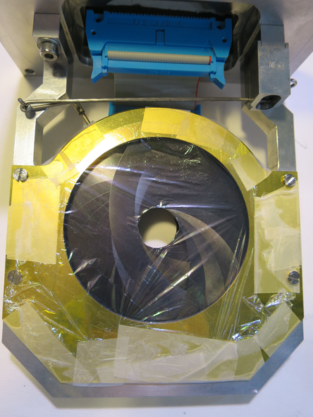
Once chamber finished venting, the far S2 was removed and its 12um mylar was replaced with 0.9um mylar ready for beam measurements at Elab = 3MeV. See picture 1 for 0.9um mylar mounted in front of far S2.
Far S2 remounted with far iris arm. Far S2 preamp remounted.
Preamp power on, currents drawn are good. Far S2 biased to -130.0V, leak I = 1.53uA. Diode biased to -70V, leak I = 0.00uA.
Noise looked ok. Detector biases off.
12:50 Ecodry 1 and 2 on. Started opening manual valve.
13:05 manual valve opened fully. T1600 valve opened.
13:10 Turbos on, pressures reached ~9e-5 mBar
Far S2 bias = -130.0V, leak I = 1.48uA. Diode bias = -70.1V, leak I = 0.00uA.
Set new RAL thresholds whilst monitoring rate: (counting from left of RAL rack)
- RAL #1 and 2: 20mV
- RAL #3: 15mV
- RAL #4 and 5: 10mV
- RAL #6: 15mV
13:25 Pressures (mBar):
- TPU1 = 1.0e-5
- TPU2 = 2.8e-6
- TPD1 = 2.5e-6
- TPD2 = 3.3e-6
- CHUP = Sensor Off
- CHDW = No Sensor
|
| Attachment 1: IMG_3273.JPG
|
|
|
65
|
Mon Dec 3 17:34:38 2018 |
Thomas Chillery, Carlo Bruno, Raffaele Buompane | 6Li(p,p): Test measurement of 1.5MeV 6Li 1+ on thin CH2 50 |
On 27/11/2018:
After tuning beam (see previous eLog entry # 64)
Run #181127193908
- Run time: 1589s
- Pulser ON, as before
- Target: CH2 50
- Beam: 1.5MeV 6Li 1+
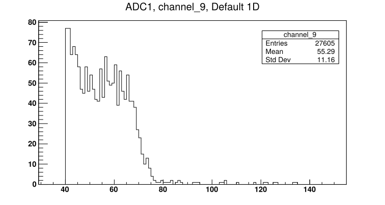
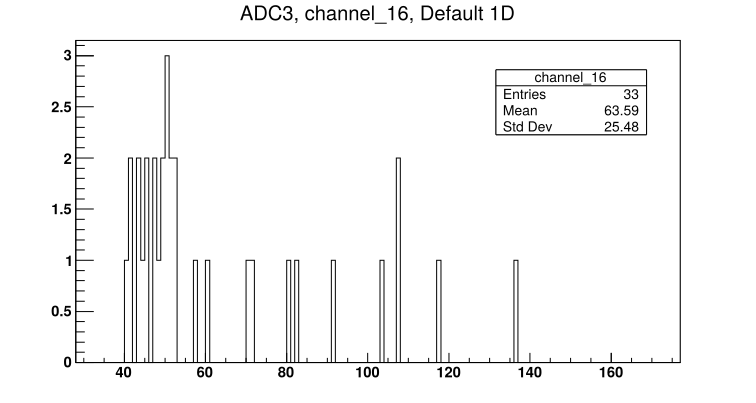
- See attached picture 1 for sample S2 front strip spectrum. See attached picture 2 for diode spectrum
|
| Attachment 1: 181127193908_ADC1_Ch9.png
|
|
| Attachment 2: 181127193908_ADC3_Ch16.png
|
|
|
66
|
Mon Dec 3 17:40:51 2018 |
Thomas Chillery, Carlo Bruno, Raffaele Buompane | Lab background |
On 27/11/2018:
Run # 181127200709
- Run time: 46329s
- Pulser ON, as before
- No target
- No beam
- Lab background
- DT ~ 12%
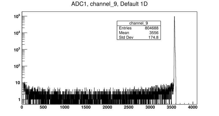
- See attached picture 1 for sample far S2 front strip spectrum. See attached picture 2 for diode spectrum.
At 20:00:
Far S2 bias = -130.0V, leak I = 1.52uA. Diode bias = -70.1V, leak I = 0.00uA. Preamps drawing correct current.
Pressures (mBar):
- TPU1 = 7.0e-6
- TPU2 = 1.9e-6
- TPD1 = 1.5e-6
- TPD2 = 1.7e-6
- CHUP = Sensor Off
- CHDW = No Sensor
Rate meter ~ 5000Hz
On 28/11/2018:
At 8:55 Far S2 bias = -130.0V, leak I = 1.67uA. Diode bias = -70.1V, leak I = 0.00uA.
Rate meter ~ 4100Hz
Pressures (mBar):
- TPU1 = 8.5e-7
- TPU2 = 6.3e-7
- TPD1 = 7.5e-7
- TPD2 = 6.5e-7
- CHUP = Sensor Off
- CHDW No Sensor
Stopped lab background run |
| Attachment 1: 181127200709_ADC1_Ch9.png
|
|
| Attachment 2: 181127200709_ADC3_Ch16.png
|
|
|
64
|
Mon Dec 3 17:02:48 2018 |
Thomas Chillery, Carlo Bruno, Lizeth Morales, Guiseppe Porzio, Raffaele Buompane | 6Li(p,p): Tuning 1.5MeV 6Li 1+ beam |
On 27/11/2018:
Started tuning for 1.5MeV 6Li 1+. Set ladder to position #2 - Blank 10mm. Far S2 iris closed.
Run # 181127151653
- Run time: N/A
- Pulser ON, as before
- Target: Blank 10mm
- Beam: 1.5MeV 6Li 1+
Moved ladder to position #5 - natC III
Run # 181127152055
- Run time: N/A
- Pulser ON, as before
- Target: natC III
- Beam: 1.5MeV 6Li 1+
- DAQ Crashed
Restarted FAIR DAQ
Run # 181127153422
- Run time: N/A
- Pulser ON, as before
- Target: natC III
- Beam: 1.5MeV 6Li 1+
- Run stopped incorrectly by user
Run # 181127153506
- Run time: 489s
- Pulser ON, as before
- Target: natC III
- Beam: 1.5MeV 6Li 1+
Run # 181127155040
- Run time: 187s
- Pulser ON, as above
- Target: natC III
- Beam: 1.5MeV 6Li 1+
Moved ladder to position #3 - CH2 XVI
Run # 181127155607
- Run time: 908s
- Pulser ON, as above
- Target: CH2 XVI
- Beam: 1.5MeV 6Li 1+
- DT ~ 15%
Struggling to see beam in diode for all of these past runs.
Opened iris to use far S2 as diagnostic tool - beam is stopped in thick CH2 targets so detector is safe even at its small angular coverage (~5 - 15 degrees)
Run # 181127161508
- Run time: 14s
- Pulser ON, as before
- Target: CH2 XVI
- Beam: 1.5MeV 6Li 1+
No high rate seen
Run # 181127161656
- Run time: 194s
- Pulser ON, as before
- Target: CH2 XVI
- Beam: 1.5MeV 6Li 1+
- DT ~ 12%
Still struggling to see beam on diode
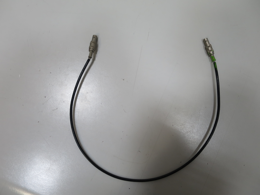
Found lemo cable used for diode timing between CFD and Logic OR has exposed cabling -> replaced lemo. See attached picture 1 for old lemo.
Run # 181127163416
- Run time: 106s
- Pulser ON, as before
- Target: CH2 XVI
- Beam: 1.5MeV 6Li 1+
Far iris opened
Run # 181127163848
- Run time: N/A
- Pulser ON, as before
- Target: CH2 XVI
- Beam: 1.5MeV 6Li 1+
Realised we were making a mistake when looking at the DAQ spectra. We were looking at ADC 2 (labelled as 3 on DAQ file browser) channel 16 (an S2 back strip) when we should have been looking at ADC 3 (labelled as 4 on DAQ browser) channel 16 for the diode
Closed iris, checked beam current. Using 10mm aperture FCC = 1pA.
Opened iris, moved ladder to position #3 - CH2 XVI
Run # 181127164749
- Run time: 556s
- Pulser ON as before
- Target: CH2 XVI
- Beam: 1.5MeV 6Li 1+
Ready to mount thin CH2 target.
At 16:55: Far S2 bias = -130.0V, leak I = 1.75uA. Diode bias = -70.1V, leak I = 0.00uA.
Pressures (mBar):
- TPU1 = 9,2e-7
- TPU2 = 3.4e-7
- TPD1 = 6.4e-7
- TPD2 = 6.8e-7
- CHUP = Sensor Off
- CHDW = No Sensor
Switched off detector biases, switched off preamps. Closed FCC valve. Closed line valve. Turbos off. T1600 backing and manual valves closed. Ecodry 1 and 2 off.
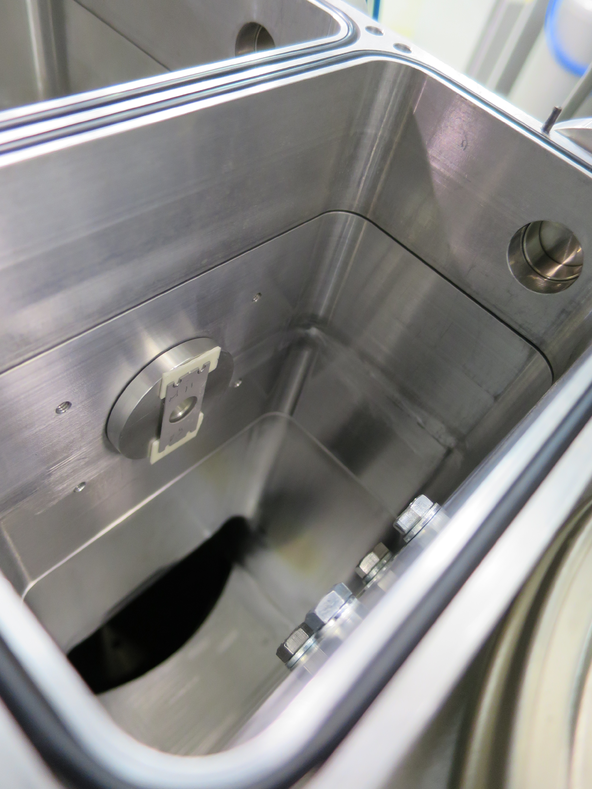
Vented chamber. Mounted thin target CH2 50 ~ 50mm from Far S2 - see attached picture 2.
Left 0.9um mylar in front of far S2.
Remounted far S2 and far preamp. With detectors on in air trigger rate ~ 9kHz.
19:00 Ecodry 1 and 2 on. Started opening manual valve.
19:15 pressures below 10 mBar, manual valve fully opened. T1600 backing valve opened. Turbos on.
19:25 Pressures (mBar):
- TPU1 = 3.2e-5
- TPU2 = 8.1e-6
- TPD1 = 6.0e-6
- TPD2 = 8.3e-6
- CHUP = Sensor Off
- CHDW = No Sensor
Far S2 biased to - 130.0V, leak I = 1.52uA. Diode biased to -70.1V, leak I = 0.00uA.
Closed iris, set ladder to position #2 - blank 10mm
See 1 -> 2 pA beam on FCC, opened iris ready for measurement. |
| Attachment 1: IMG_3285.JPG
|
|
| Attachment 2: IMG_3292.JPG
|
|
|
63
|
Mon Dec 3 16:47:40 2018 |
Thomas Chillery, Carlo Bruno, Lizeth Morales | Finishing 3.0MeV 7Be measurements with CH2 XIX and natC III |
On 27/11/2018:
At 8:40 Far S2 bias = -130.0V, leak I = 1.74uA. Diode bias = -70.1V, leak I = 0.00uA.
Pressures (mBar):
- TPU1 = 8.3e-7
- TPU2 = 3.4e-7
- TPD1 = 6.5e-7
- TPD2 = 6.5e-7
- CHUP = Sensor Off
- CHDW = No Sensor
Preamps still drawing necessary currents.
Stopped overnight run of 3.0MeV 7Be 2+ on CH2 XIX
Checked beam current: FC4 = 2pA.
Moved ladder to position #5 - natC III
Run # 181127085408
- Run time: 627s
- Pulser ON, as before
- Target: natC III
- Beam: 3.0MeV 7Be 2+
- DT ~ 23%
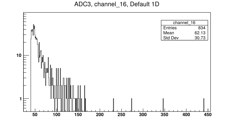
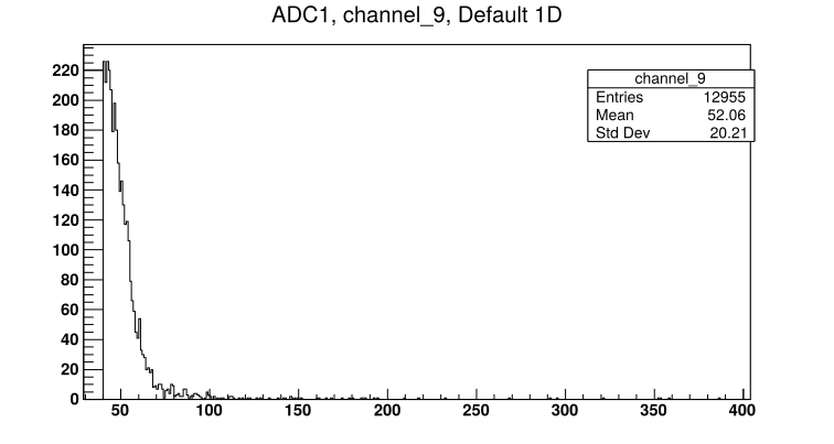
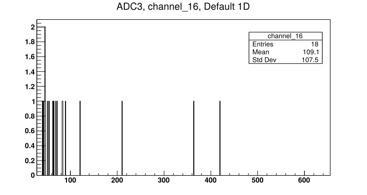
- See attached picture 1 for sample S2 front strip spectrum. See attached picture 2 for diode spectrum.
Moved ladder to position #2 - 10mm aperture
Run # 181127090808
- Run time: 601s
- Pulser ON, as before
- Target: Blank 10mm aperture
- Beam: 3.0MeV 7Be 2+
- DT ~ 10%
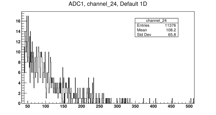
- See attached picture 3 for Far S2 innermost strip spectrum.
Moved ladder to position #7 - CH2 XIX
Run # 181127092128
- Run time: 663s
- Pulser ON, as before
- Target: CH2 XIX
- Beam: 3.0MeV 7Be 2+
- DT ~ 10%
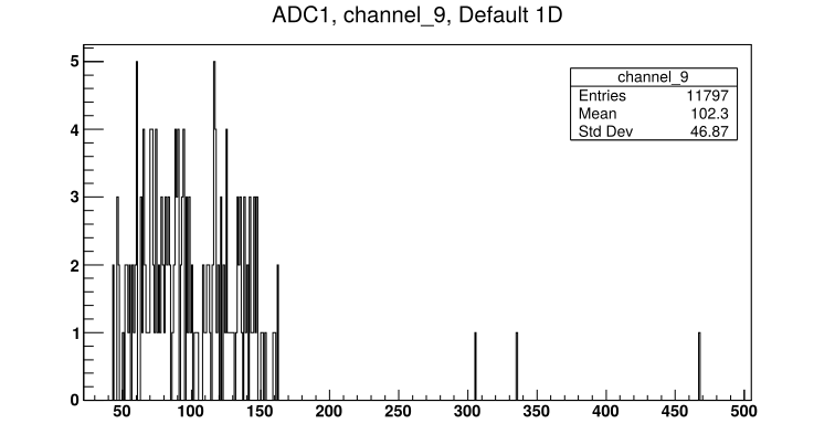
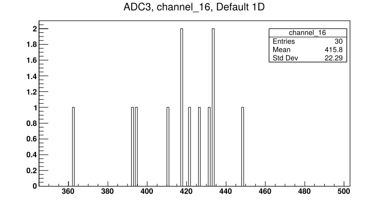
- See attached picture 4 for sample S2 front strip spectrum. See attached picture 5 for diode spectrum.
* End of 7Be beam * |
| Attachment 1: 181127085408_ADC1_Ch9.png
|
|
| Attachment 2: 181127085408_ADC3_Ch16.png
|
|
| Attachment 3: 181127090808_ADC1_24.png
|
|
| Attachment 4: 181127092128_ADC1_Ch9.png
|
|
| Attachment 5: 181127092128_ADC3_Ch16.png
|
|
|
1
|
Tue Aug 1 12:26:13 2017 |
Thomas Chillery | 10th - 22nd July 2017 Summary Report |
Attached is a report summarising work performed on the electronics and target chamber in CIRCE from the 10th to the 22nd July 2017.
Outstanding problems have also been listed. |
| Attachment 1: Summary.docx
|
|
4
|
Thu Feb 15 20:45:27 2018 |
Thomas Chillery | Planning - Target Chamber CAD diagram |
Find attached the latest CAD diagram of the Target Chamber, drawn by Peter Black |
| Attachment 1: solid_target_11.pdf
|

|
|
6
|
Fri Feb 16 18:21:17 2018 |
Thomas Chillery | Iris arm problems |
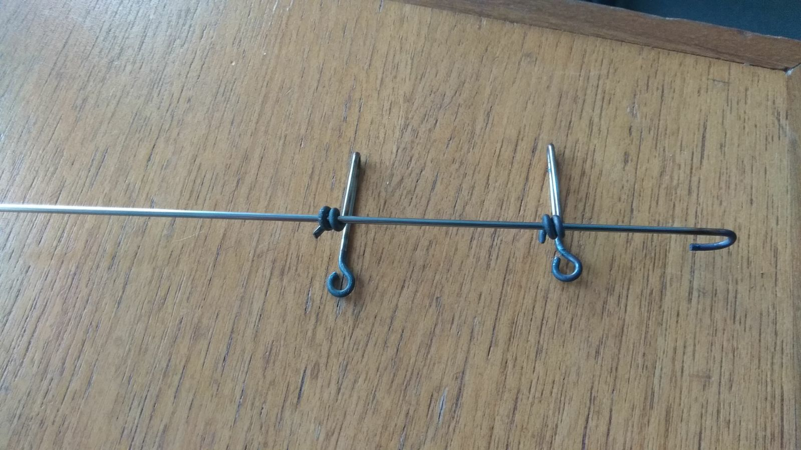
After lunch we were still having problems with the aperture hook, see first attached image highlighting the arm is located in close proximity (but not touching) the vacuum feedthrough and ribbon cable.
Meanwhile in Edinburgh Peter Black designed and built an additional component of the hook to assist in connecting it between the actuator and iris arms, see second attached image.
I decided enough time had been spent on this so far and to go ahead with testing the chamber vacuum. |
| Attachment 1: IMG_2677.JPG
|

|
| Attachment 2: ApertureArm_PetersSolution.jpg
|
|
|
8
|
Sat Feb 17 12:35:25 2018 |
Thomas Chillery | Setup - Electronic Cabling |
Between 9:00 to 12:30 this morning Filipo was working on the weekend 14C measurements, allowing me to work in the lab during this period.
I unpacked four MALU 4532 Lecroy Logic Modules (sent to CIRCE two weeks ago). Three of these modules were installed into the 1434A CAMAC crate, which already had one module installed from the July 2017 shift. One module remains out of the crate as a spare.
I connected 16 way - 16 way ribbon cables between the front of both IDC converter boxes to the back of the RAL shaping amplifier modules. They are connected as follows:
- RAL shaping amps I, II, XI, and IV are connected to top convertor box inputs 0->3, counting from the left when facing the rack
- RAL shaping amps V, VI, VII, and VIII are connected to top convertor box inputs 4->7
- RAL shaping amps X, XII, XIII, and "R" are connected to bottom convertor box inputs 8->11
- RAL shaping amps "S", "Q", "u", and "W" are connected to bottom convertor box inputs 12->15
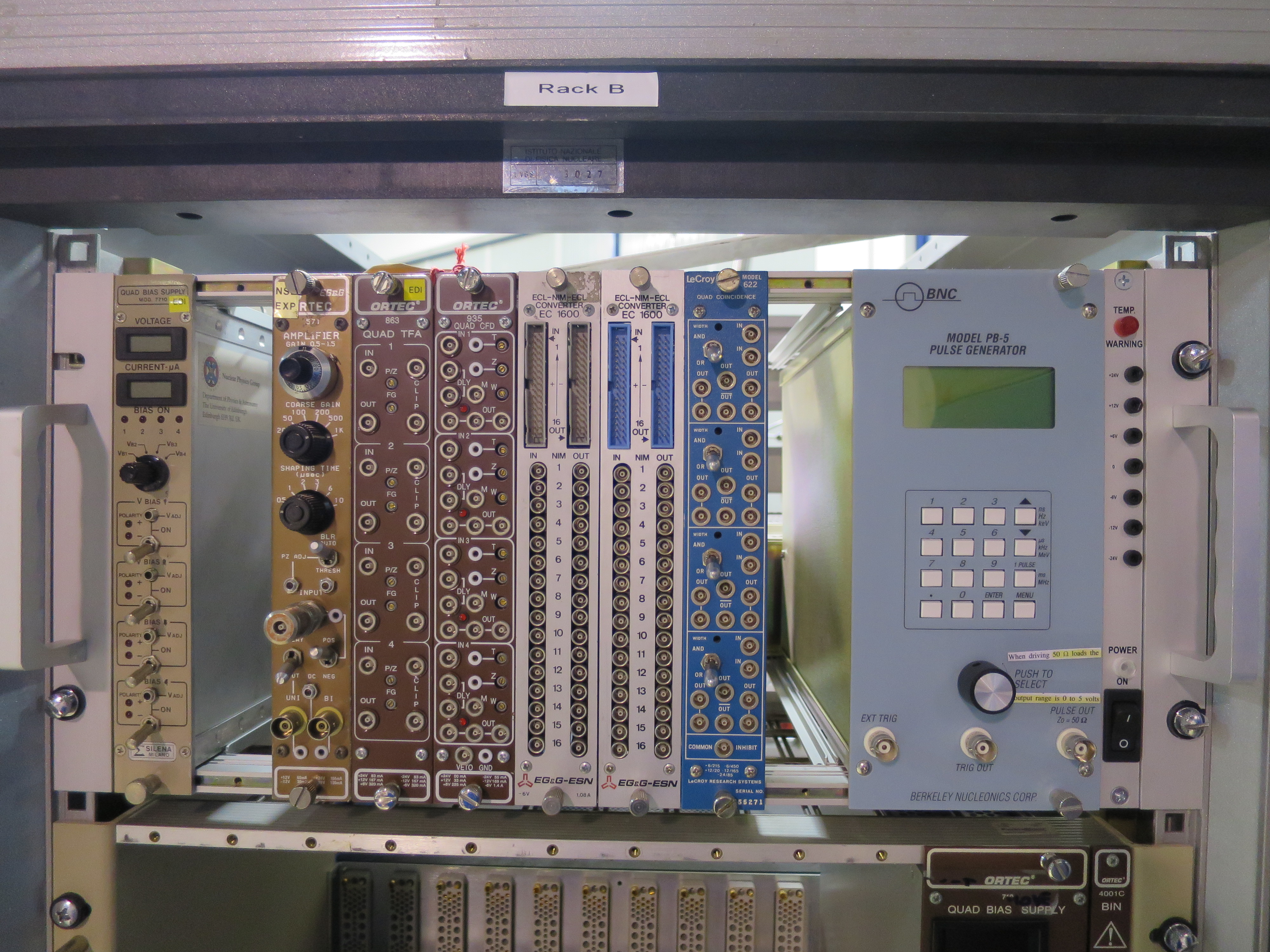
In second electronics rack, "Rack B", at the top is a Nim bin used last July 2017 for the Si diode.
In this nim bin I installed two NIM-ECL-NIM converters and the PB-5 Pulser Generator
Currently in the Nim bin from left to right we have the following:
- Silena mod 7710 Quad Bias Supply
- Ortec 571 Amplifier
- Ortec 863 Quad TFA
- Ortec 935 Quad CFD
- Two ECL-Nim-ECL Converters, Model EC1600 by EG&G-ESN
- Lecroy Model 622 Quad Coincidence Unit
- PB-5 Pulse Generator
The Nim bin was switched on in this configuration, I checked the supplied voltages with a voltmeter. All voltages, -6, +6, -12, +12, -24, and +24V read correctly.
Next I installed 5m 34 way - 34 way ribbon cables labelled 0, 1, 2, and 3 into the back of the top convertor box, including the grounding cable. Now:
- Cable 0 in back splits into cables 0 and 1 in front
- Cable 1 in back splits into cables 2 and 3 in front
- Cable 2 in back splits into cables 4 and 5 in front
- Cable 3 in back splits into cables 6 and 7 in front
Next I installed 5m 34 way - 34 way ribbon cables labbeled 13, 14, 15, and 16 into the back of the bottom convertor box, including the grounding cable. Now:
- Cable 13 in back splits into cables 8 and 9 in front
- Cable 14 in back splits into cables 10 and 11 in front
- Cable 15 in back splits into cables 12 and 13 in front
- Cable 16 in back splits into cables 14 and 15 in front
The other end of these eight 5m long cables are ready to be plugged into the EDI preamps
I then plugged 16-way ribbon cables into the Analogue Output of the RAL shaping amplifiers in the following order, where ADC ... is the label of the cables:
- RAL I -> ADC 8A
- RAL II -> ADC 8B
- RAL XI -> ADC 9A
- RAL IV -> ADC 9B
- RAL V -> ADC 10A
- RAL VI -> ADC 10B
- RAL VII -> ADC 11A
- RAL VIII -> ADC 11B
- RAL X -> ADC 12A
- RAL XII -> ADC 12B
- RAL XIII -> ADC 13A
- RAL "R" -> ADC 13B
- RAL "S" -> ADC 14A
- RAL "Q" -> ADC 14B
- RAL "u" -> ADC 15A
Some of the RAL "W" Analogue pins were slightly off center. Filipo needed to leave so I left cable ADC 15B unplugged.
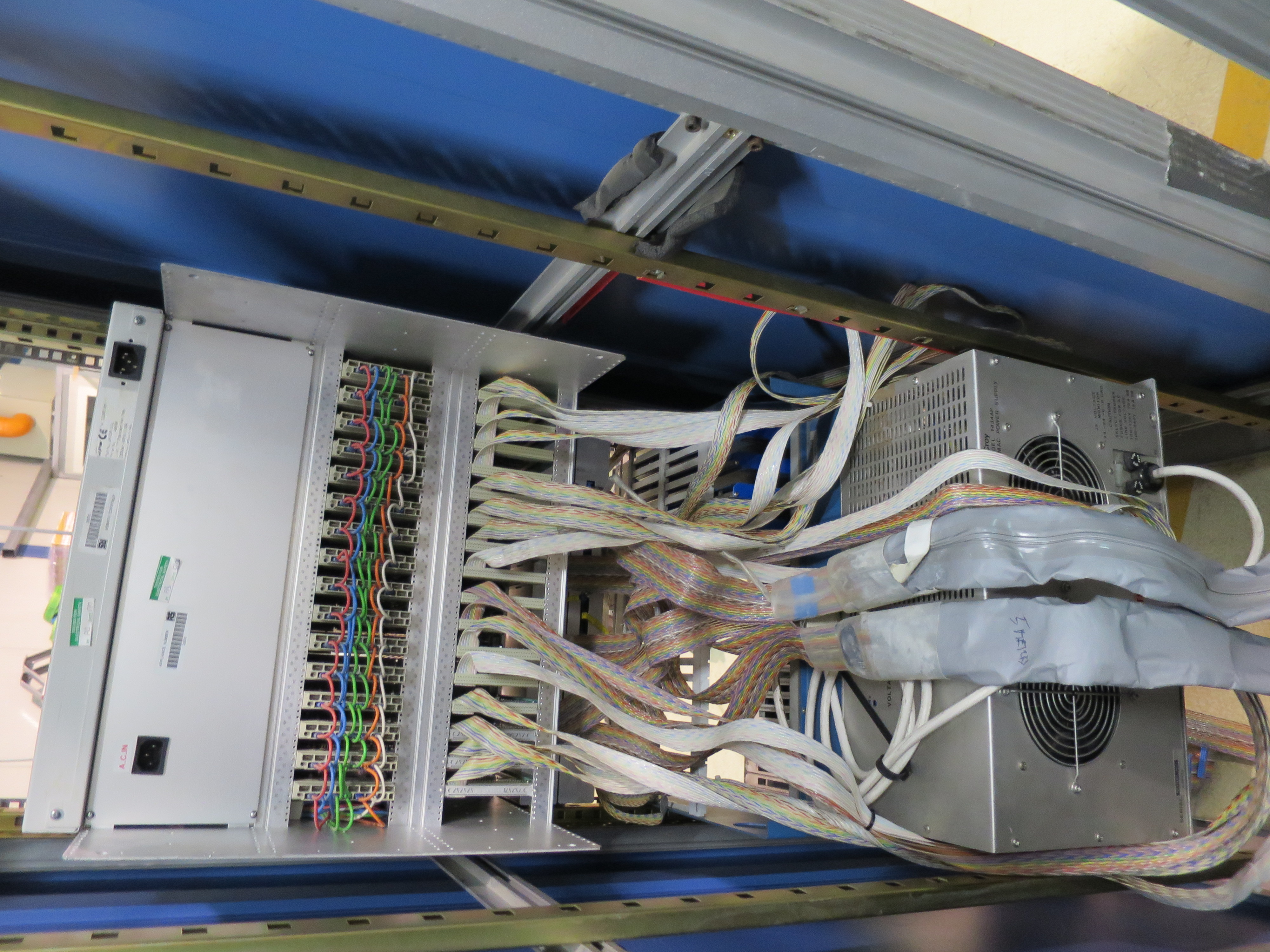
I attach photos of the current status of both electronics racks |
| Attachment 1: IMG_2697.JPG
|

|
| Attachment 2: IMG_2702.JPG
|
|
| Attachment 3: IMG_2704.JPG
|

|
| Attachment 4: IMG_2706.JPG
|
|
|
9
|
Sat Feb 17 13:00:51 2018 |
Thomas Chillery | Test - S2 Detector Bias |
This morning whilst I was setting up the ribbon cabling (see eLog entry #8) I was considering collecting a voltage bias vs leakage current curve for one/two of the S2 detectors, depending on time available.
This would involve using the central section of the chamber and the straight spacer box to mount the preamp on top of the lid.
Note: we currently cannot use the angled spacer boxes for the chamber yet, because these need to be trimmed by Antonio (the technician) to allow more space for the ribbon cables and also allow the box to sit flat on top of the vacuum feedthrough. We will be seeing Antonio on monday morning to prioritise required machine work.
However, I then remembered that after we stopped the pumps last night we did not vent the chamber. This morning at 10:52 the labview program used to control the pumps read the following pressures:
- Turbo Up 1 = 1000mBar
- Turbo Up 2 = 389mBar
- Turbo Down 1 = 86.1mBar
- Turbo Down 2 = 49.7mBar
- Chamber Up = 1000mBar
- Chamber Down = 139mBar
I emailed Lucio to see if he could come in this weekend to vent the chamber and we could then mount and test two of the S2 detectors, one after the other. Otherwise we can do this monday morning.
As an aside there is some serendipity here, the pressures I read this morning indicate if there is a leak in the chamber it is more likely to be found upstream. |
|
11
|
Tue Feb 20 16:57:49 2018 |
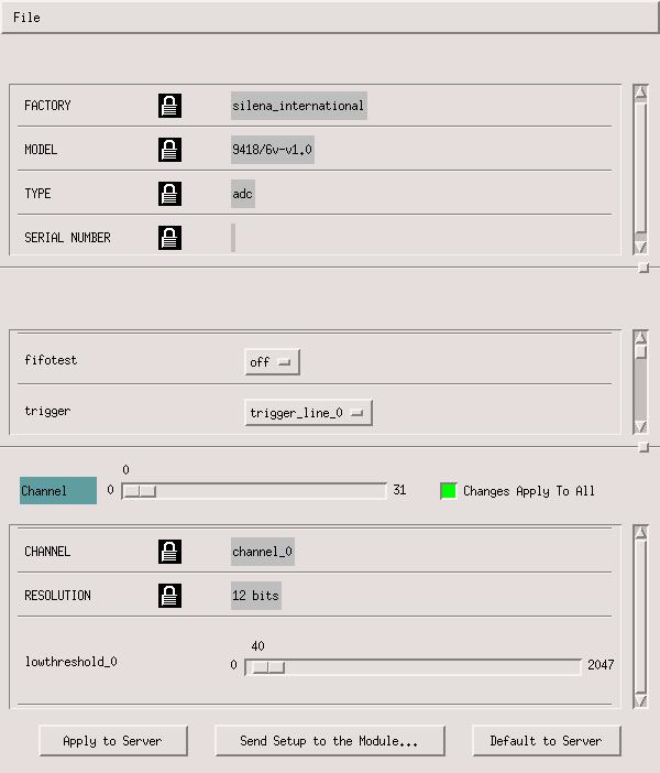
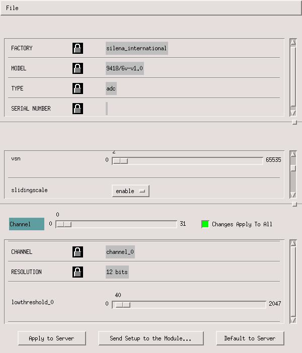
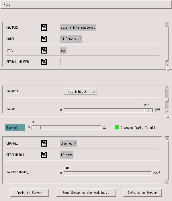
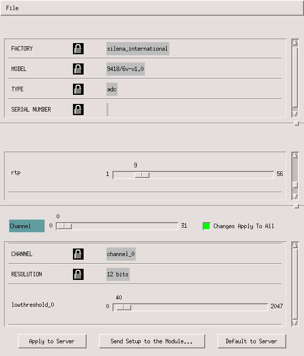
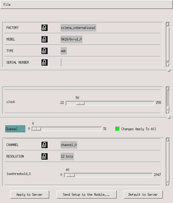
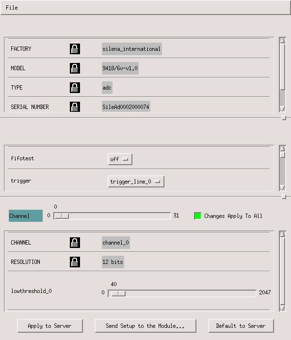
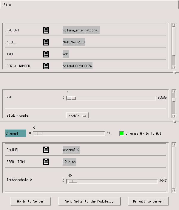
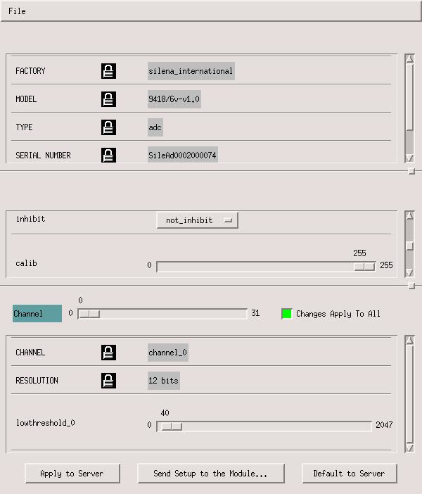
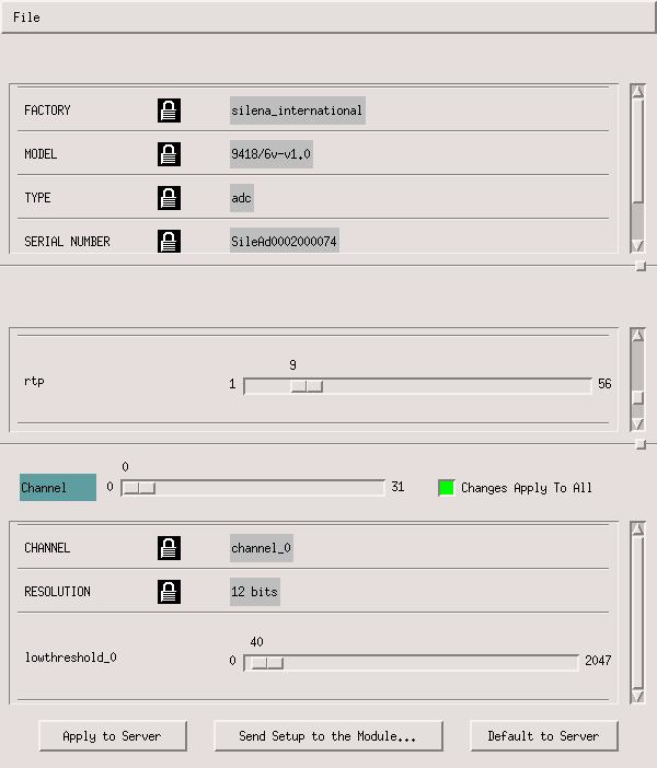
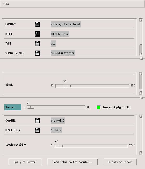
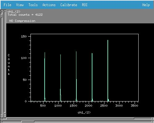
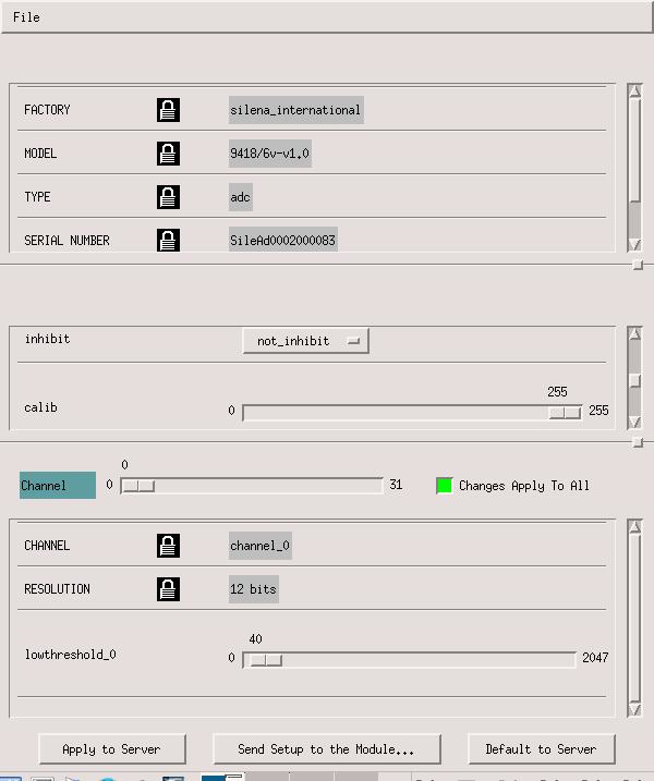
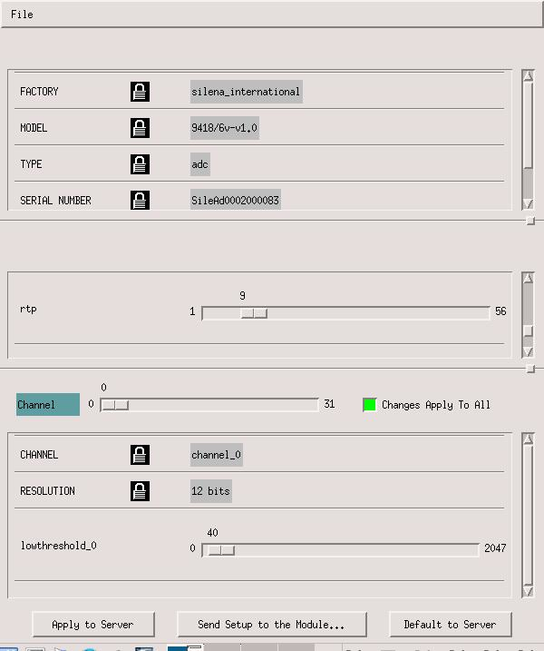
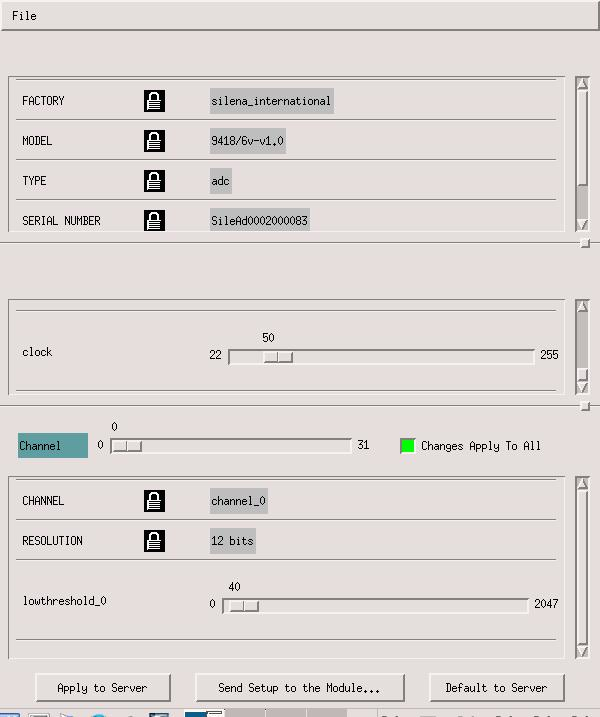
Thomas Chillery | Screenshots - ADC 2 and ADC 4 settings, and example pulser walkthrough |
|
| Attachment 1: ADC2_Settings1.jpg
|
|
| Attachment 2: ADC2_Settings2.jpg
|
|
| Attachment 3: ADC2_Settings3.jpg
|
|
| Attachment 4: ADC2_Settings4.jpg
|
|
| Attachment 5: ADC2_Settings5.jpg
|
|
| Attachment 6: ADC4_Settings1.jpg
|
|
| Attachment 7: ADC4_Settings2.jpg
|
|
| Attachment 8: ADC4_Settings3.jpg
|
|
| Attachment 9: ADC4_Settings4.jpg
|
|
| Attachment 10: ADC4_Settings5.jpg
|
|
| Attachment 11: BKG_zoombeam1.jpg
|
|
|
16
|
Thu Feb 22 14:55:09 2018 |
Thomas Chillery | ADC6 Settings |
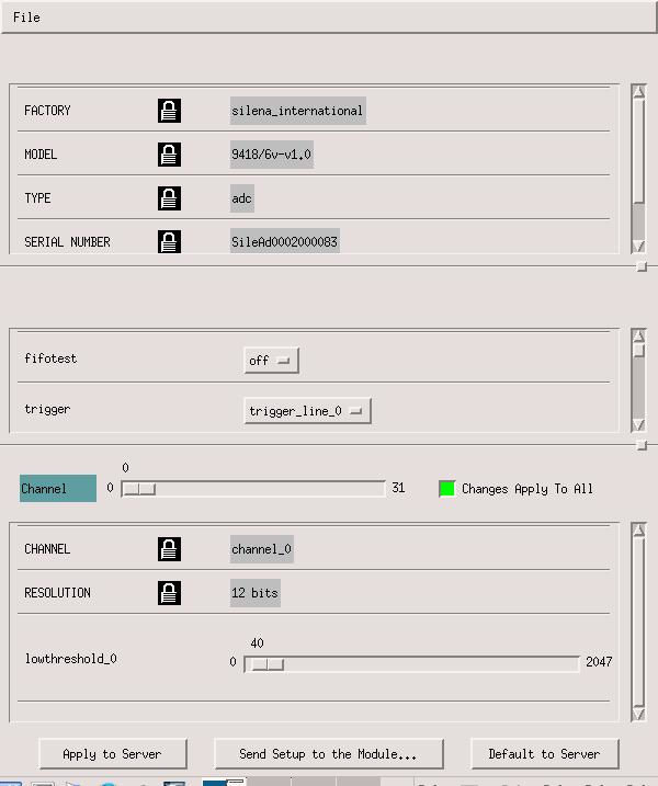
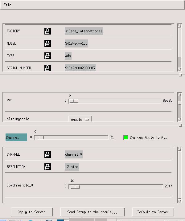
DAQ Settings for ADC6 settings attached. ADC 6 has been used for the pin diode during the week starting 19/02/2018 |
| Attachment 1: ADC6_Settings1.jpg
|
|
| Attachment 2: ADC6_Settings2.jpg
|
|
| Attachment 3: ADC6_Settings3.jpg
|
|
| Attachment 4: ADC6_Settings4.jpg
|
|
| Attachment 5: ADC6_Settings5.jpg
|
|
|
40
|
Wed Jul 11 15:55:35 2018 |
Thomas Chillery | Electronics Channel Map |
See attached for Electronics Channel Map spreadsheet.
This is valid for the February 2018 Beamtime; it maps out the Far S2 Strips onto the ADC channels
A map should be produced and updated for each beamtime to ensure S2 Strip -> ADC Channel is correctly documented. |
| Attachment 1: Electronics_Channel_Map.ods
|
|
74
|
Tue Dec 4 09:38:18 2018 |
Thomas Chillery | 181122 Electronics Map |
See attached for S2 electronics map, following channels from S2 outputs to ADC inputs
For the 19/11/2018 - 29/11/2018 beamtime only the Far S2 was in operation |
| Attachment 1: 181122_Electronics_Channel_Map.ods
|
| Attachment 2: 181122_Electronics_Channel_Map.xls
|
|
75
|
Tue Dec 4 09:40:31 2018 |
Thomas Chillery | Preliminary measurements of target activation using geiger counter |
On 29/11/2018 at 17:40 a rough measurement of the irradiated target activity was performed using a geiger counter.
The geiger counter was a calibrated Berthold LB124, which was placed a fixed 15mm distance from each target.
The calibration was such that 1cps = 37kBq.
The LB124 counter measured a background count of 0.5cps
| Target |
Irradiated with |
Berthold LB124 [cps] |
| CH2 XV |
7Li 4.0MeV |
0.0 |
| CH2 XVI |
7Li and 7Be 4.0MeV, 7Li 6.0MeV |
6.8 |
| CH2 XVIII |
7Li and 7Be 6.0MeV |
0.9 |
| CH2 XX |
Not used |
0.5 |
| natC III |
7Li and 7Be 3.0MeV, 4.0MeV, and 6.0MeV |
0.0 |
| CH2 XIX |
7Li and 7Be 3.0MeV |
11.5 |
|
|
76
|
Tue Dec 4 11:23:29 2018 |
Thomas Chillery | Chamber Dimensions |
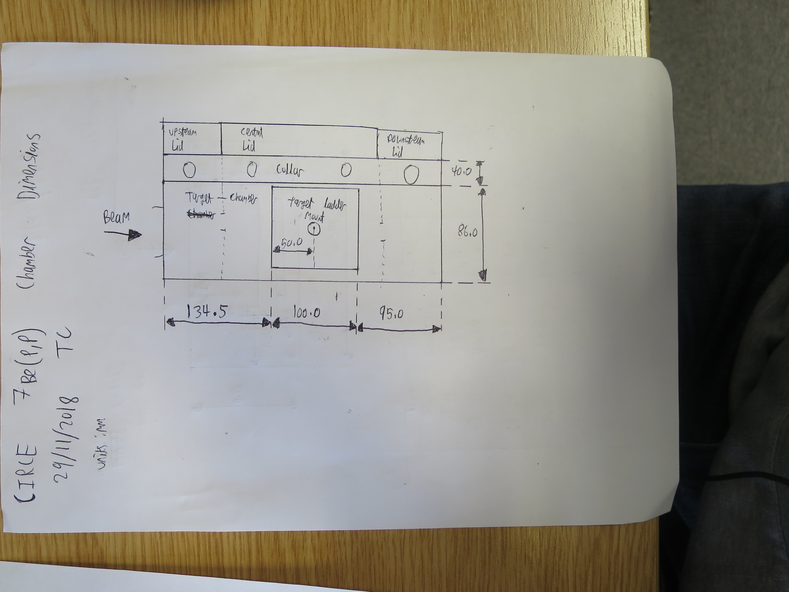
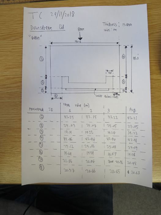
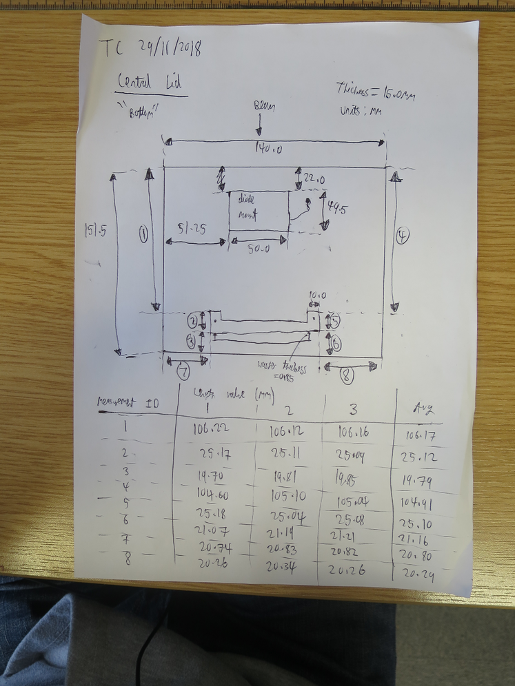
See attached pictures for measurements of the 7Be(p,p) chamber dimensions.
The target ladder center - Far S2 distance = 50 + 95 + 0.85 - (19.22+19.58)/2 = 126.45 mm |
| Attachment 1: IMG_3397.JPG
|
|
| Attachment 2: IMG_3398.JPG
|
|
| Attachment 3: IMG_3399.JPG
|
|
|
77
|
Wed Sep 18 14:01:13 2019 |
Thomas Chillery | Logbook Spreadsheet |
See attached for the logbook |
| Attachment 1: 181123_Logbook.xls
|
|
78
|
Tue Feb 18 14:39:26 2020 |
Thomas Chillery | Target Thicknesses |
Excel spreadsheet showing CH2 and natC target thicknesses attached |
| Attachment 1: Target_List.xls
|