| |
ID |
Date |
Author |
Subject |
|
|
22
|
Thu Jan 24 17:16:32 2019 |
CA, TD, NH, VP | MACB time switch settings |
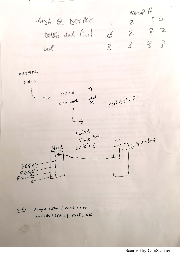
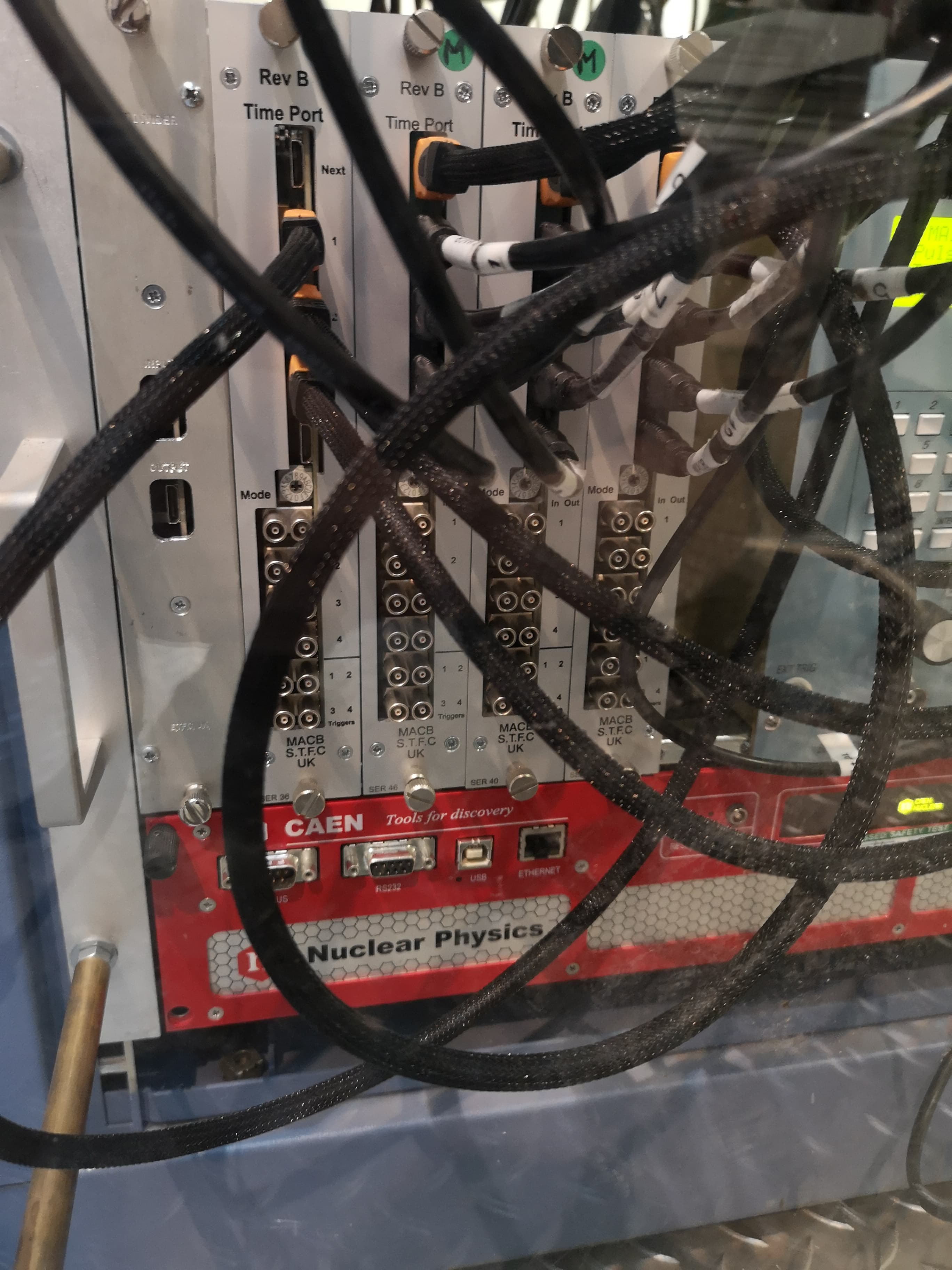
AIDA@DESPEC MACB time switch settings before and after WR are as follows.

Attachment 1 - MACB 1-4 from left to right

MACB number:                           1        2        3        4

100MHZ clock setting (before WR):      0        2        2        2

White Rabbit setting (after WR): 3 3 3 3 |
| Attachment 1: 50668223_286084358731841_9104059387265155072_n.jpg
|

|
| Attachment 2: despecmacb.pdf
|
|
|
|
517
|
Wed Jan 18 13:40:33 2023 |
PJCS TD | MACB settings with either Emulator or VITAR |
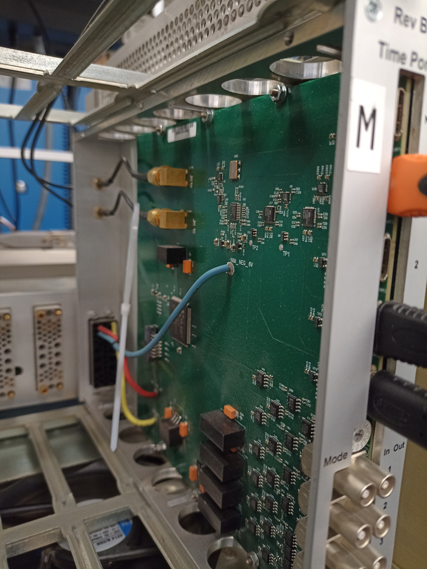
When using the VETAR connected to the HDMI port of the root MACB the settings for all the MACB in the system 0x3.
This setting takes the Clock and Data line from the input HDMI and outputs it via teh HDMI output ports.
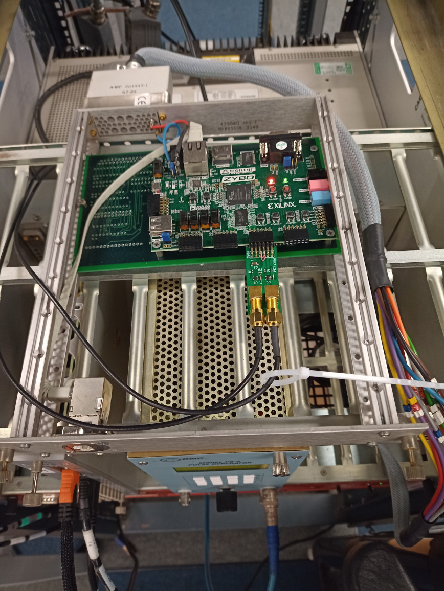
When using the Emulator connected via the SMA connectors on the back of the root MACB then the setting for the root MACB should be 0xD and all others should be 0x3.
Attached is the .jed file for programming the MACB and the .vhd source file to help with understanding of the settings. |
| Attachment 1: macb_apr20.jed
|
| Attachment 2: macb_apr20.vhd
|
----------------------------------------------------------------------------------
-- Company:
-- Engineer:
--
-- Create Date:    17:03:27 03/16/2011
-- Design Name:
-- Module Name:    macb_top - Behavioral
-- Project Name:
-- Target Devices:
-- Tool versions:
-- Description:
--
-- Dependencies:
--
-- Revision:
-- Revision 0.01 - File Created
-- Additional Comments:
--
----------------------------------------------------------------------------------
library IEEE;
use IEEE.STD_LOGIC_1164.ALL;
use IEEE.STD_LOGIC_ARITH.ALL;
use IEEE.STD_LOGIC_UNSIGNED.ALL;

---- Uncomment the following library declaration if instantiating
---- any Xilinx primitives in this code.
library UNISIM;
use UNISIM.VComponents.all;
-- NOTE all in/out notations are relative to this unit
entity macb_apr20 is
    Port (
			  port1_sp : inout  STD_LOGIC_VECTOR (3 downto 0);
			  port2_sp : inout  STD_LOGIC_VECTOR (3 downto 0);
			  port3_sp : inout  STD_LOGIC_VECTOR (3 downto 0);
			  port4_sp : inout  STD_LOGIC_VECTOR (3 downto 0);
			  layer_sp : inout  STD_LOGIC_VECTOR (3 downto 0);
			  layer_trigger : out std_logic ;
           sync_return : in  STD_LOGIC_VECTOR (3 downto 1);
           selector : in  STD_LOGIC_VECTOR (3 downto 0);
           sync_select : out  STD_LOGIC_vector(1 downto 0 );
           clock200_select : out  STD_LOGIC_vector( 1 downto 0 ) ;
			  butis_divide_reset : out std_logic ;
			  butis_divide_s : out std_logic_vector( 2 downto 0 ) ;
			  clock_5 : in std_logic ;
			  sync_5 : in std_logic ;
			  trigger : in std_logic_vector( 3 downto 0 ) ;
           MBS_in : in  STD_LOGIC_VECTOR (3 downto 0);
           MBS_out : out  STD_LOGIC_VECTOR (3 downto 0));
end macb_apr20;

architecture Behavioral of macb_apr20 is
signal port1_spi :  STD_LOGIC_VECTOR (3 downto 0) := ( others => '0' );
signal port1_spo :  STD_LOGIC_VECTOR (3 downto 0) := ( others => '0' );
signal port1_t :  STD_LOGIC_VECTOR (3 downto 0) := ( others => '1' );
signal port2_spi :  STD_LOGIC_VECTOR (3 downto 0) := ( others => '0' );
signal port2_spo :  STD_LOGIC_VECTOR (3 downto 0) := ( others => '0' );
signal port2_t :  STD_LOGIC_VECTOR (3 downto 0) := ( others => '1' );
signal port3_spi :  STD_LOGIC_VECTOR (3 downto 0) := ( others => '0' );
signal port3_spo :  STD_LOGIC_VECTOR (3 downto 0) := ( others => '0' );
signal port3_t :  STD_LOGIC_VECTOR (3 downto 0) := ( others => '1' );
signal port4_spi :  STD_LOGIC_VECTOR (3 downto 0) := ( others => '0' );
signal port4_spo :  STD_LOGIC_VECTOR (3 downto 0) := ( others => '0' );
signal port4_t :  STD_LOGIC_VECTOR (3 downto 0) := ( others => '1' );
signal layer_spi :  STD_LOGIC_VECTOR (3 downto 0) := ( others => '0' );
signal layer_spo :  STD_LOGIC_VECTOR (3 downto 0) := ( others => '0' );
signal layer_t :  STD_LOGIC_VECTOR (3 downto 0) := ( others => '1' );
signal seli : integer range 0 to 15 := 0  ;
-- well really
signal MBS_in_n : std_logic_vector( 3 downto 0 ) := "0000" ;
begin
MBS_in_n <= ( not MBS_in);
seli <= conv_integer(not selector) ;
-- MBS signal allocations to sp lines and HDMI pin. This maps to NIM connections
-- 0 :	MBS_clock10 	SP0	13
-- 1 :	MBS_reset		SP1	14
-- 2 :	MBS_reset_rq	SP2	15
-- 3 :	MBS_Trigger		SP3	16
layer_trigger <= trigger(0) or trigger(1) or trigger(2) or trigger(3) ;

-- divider controls set for pass-through
butis_divide_reset <= '1' ; -- for now don't reset ;

process ( seli , MBS_in_n, port1_spi, port2_spi, port3_spi, port4_spi, layer_spi, sync_return ,sync_5  )
-- note : & => concatenate
begin
	case seli is
	when 0 => --- Master/ Root / MBS / Internal clock
		port1_spo <= MBS_in_n(3) & MBS_in_n(2) & '0' & '0' ;
		port1_t <= "0011" ; -- drive trigger and reset request only
		port2_spo <= MBS_in_n(3) & '0' & port1_spi(1) & port1_spi(0) ;
		port2_t <= "0100" ; -- drive clock, reset, trigger only
		port3_spo <= MBS_in_n(3) & '0' & port1_spi(1) & port1_spi(0) ;
		port3_t <= "0100" ; -- drive clock, reset, trigger only
		port4_spo <= MBS_in_n(3) & '0' & port1_spi(1) & port1_spi(0) ;
		port4_t <= "0100" ; -- drive clock, reset, trigger only
		layer_spo <= ( others => '0' ) ;
		layer_t <= ( others => '1' ) ; -- disable the drive to the "next" port
		sync_select <= "00" ; -- select sync from port 1
		clock200_select <= "00" ; -- select internal 200 MHz oscillator
		MBS_out <=  MBS_in_n(3) & MBS_in_n(2) & port1_spi(1) & port1_spi(0) ;
		butis_divide_s <= "000" ; -- s2 is 0 for pass,

	when 1 => --- Master/ Root / MBS / BuTiS clock and SYNC
		port1_spo <= MBS_in_n(3) & MBS_in_n(2) & '0' & '0' ;
		port1_t <= "0011" ; -- drive trigger and reset request only
		port2_spo <= MBS_in_n(3) & '0' & port1_spi(1) & port1_spi(0) ;
		port2_t <= "0100" ; -- drive clock, reset, trigger only
		port3_spo <= MBS_in_n(3) & '0' & port1_spi(1) & port1_spi(0) ;
		port3_t <= "0100" ; -- drive clock, reset, trigger only
		port4_spo <= MBS_in_n(3) & '0' & port1_spi(1) & port1_spi(0) ;
		port4_t <= "0100" ; -- drive clock, reset, trigger only
		layer_spo <= ( others => '0' ) ;
		layer_t <= ( others => '1' ) ; -- disable the drive to the "next" port
		sync_select <= "01" ; -- select sync from external using SMA input
		clock200_select <= "01" ; -- select external 200 MHz oscillator using SMA input
		MBS_out <=  MBS_in_n(3) & MBS_in_n(2) & port1_spi(1) & port1_spi(0) ;
		butis_divide_s <= "000" ; -- s2 is 0 for pass,

	when 2 => --- Master/ Branch / MBS / Next layer clock next layer SYNC
		port1_spo <= layer_spi(3) & layer_spi(2) & '0' & '0' ;
		port1_t <= "0011" ; -- drive trigger and reset request only
		port2_spo <= layer_spi(3) & '0' & port1_spi(1) & port1_spi(0) ;
		port2_t <= "0100" ; -- drive clock, reset, trigger only
		port3_spo <= layer_spi(3) & '0' & port1_spi(1) & port1_spi(0) ;
		port3_t <= "0100" ; -- drive clock, reset, trigger only
		port4_spo <= layer_spi(3) & '0' & port1_spi(1) & port1_spi(0) ;
		port4_t <= "0100" ; -- drive clock, reset, trigger only
		layer_spo <=  '0' & '0' & port1_spi(1) & port1_spi(0) ; -- drive the clock and reset down a layer
		layer_t <= "1100" ; -- just drive the bottom two bits to the "next" port
		sync_select <= "10" ; -- select sync from next_layer
		clock200_select <= "10" ; -- select clock from next layer
		MBS_out <=  layer_spi(3) & layer_spi(2) & port1_spi(1) & port1_spi(0) ;
		butis_divide_s <= "000" ; -- s2 is 0 for pass,

	when 3 => --- Slave / Branch / MBS / Next layer clock and sync
		port1_spo <= layer_spi(3) & '0'  & layer_spi(1) & layer_spi(0);
		port1_t <= "0100" ; -- drive clock, reset, trigger only
		port2_spo <= layer_spi(3) & '0' & layer_spi(1) & layer_spi(0) ;
		port2_t <= "0100" ; -- drive clock, reset, trigger only
		port3_spo <= layer_spi(3) & '0' & layer_spi(1) & layer_spi(0) ;
		port3_t <= "0100" ; -- drive clock, reset, trigger only
		port4_spo <= layer_spi(3) & '0' & layer_spi(1) & layer_spi(0) ;
		port4_t <= "0100" ; -- drive clock, reset, trigger only
		layer_spo <=  '0' & '0' & '0' & '0' ; -- drive nothing
		layer_t <= "1111" ; -- just drive nothing down
		sync_select <= "10" ; -- select sync from next layer
		clock200_select <= "10" ; -- select clock from next layer
		MBS_out <=  layer_spi ; -- map all the signals for monitoring ?
		butis_divide_s <= "000" ; -- s2 is 0 for pass,

	when 4 => --- Master/ Root / MBS / BuTiS clock / Internal SYNC / External timestamp reset
		port1_spo <= MBS_in_n(3) & '0' & MBS_in_n(1)  & '0' ;
		port1_t <= "0100" ; -- drive clock, reset, trigger only
		port2_spo <= MBS_in_n(3) & '0' & MBS_in_n(1)  & '0' ;
		port2_t <= "0100" ; -- drive clock, reset, trigger only
		port3_spo <= MBS_in_n(3) & '0' & MBS_in_n(1)  & '0' ;
		port3_t <= "0100" ; -- drive clock, reset, trigger only
		port4_spo <= MBS_in_n(3) & '0' & MBS_in_n(1)  & '0' ;
		port4_t <= "0100" ; -- drive clock, reset, trigger only
		layer_spo <= ( others => '0' ) ;
		layer_t <= ( others => '1' ) ; -- disable the drive to the "next" port
		sync_select <= "00" ; -- select sync from port 1
		clock200_select <= "01" ; -- select external 50 MHz oscillator using SMA input
		MBS_out <=  MBS_in_n(3) & MBS_in_n(2) & MBS_in_n(1) & sync_5 ;
		butis_divide_s <= "000" ; -- s2 is 0 for pass,

	when 5 => --- Master/ Root / MBS / External 50Mhz clock / Internal Sync
		port1_spo <= MBS_in_n(3) & MBS_in_n(2) & '0' & '0' ;
		port1_t <= "0011" ; -- drive trigger and reset request only
		port2_spo <= MBS_in_n(3) & '0' & port1_spi(1) & port1_spi(0) ;
		port2_t <= "0100" ; -- drive clock, reset, trigger only
		port3_spo <= MBS_in_n(3) & '0' & port1_spi(1) & port1_spi(0) ;
		port3_t <= "0100" ; -- drive clock, reset, trigger only
		port4_spo <= MBS_in_n(3) & '0' & port1_spi(1) & port1_spi(0) ;
		port4_t <= "0100" ; -- drive clock, reset, trigger only
		layer_spo <= ( others => '0' ) ;
		layer_t <= ( others => '1' ) ; -- disable the drive to the "next" port
		sync_select <= "00" ; -- select sync from port 1
		clock200_select <= "01" ; -- select external SMA input
		MBS_out <=  MBS_in_n(3) & MBS_in_n(2) & port1_spi(1) & port1_spi(0) ;
		butis_divide_s <= "000" ; -- s2 is 0 for pass through.

	when 6 => --- Master/ Root / MBS / External 100Mhz clock / Internal Sync
		port1_spo <= MBS_in_n(3) & MBS_in_n(2) & '0' & '0' ;
		port1_t <= "0011" ; -- drive trigger and reset request only
		port2_spo <= MBS_in_n(3) & '0' & port1_spi(1) & port1_spi(0) ;
		port2_t <= "0100" ; -- drive clock, reset, trigger only
		port3_spo <= MBS_in_n(3) & '0' & port1_spi(1) & port1_spi(0) ;
		port3_t <= "0100" ; -- drive clock, reset, trigger only
		port4_spo <= MBS_in_n(3) & '0' & port1_spi(1) & port1_spi(0) ;
		port4_t <= "0100" ; -- drive clock, reset, trigger only
		layer_spo <= ( others => '0' ) ;
		layer_t <= ( others => '1' ) ; -- disable the drive to the "next" port
		sync_select <= "00" ; -- select sync from port 1
		clock200_select <= "01" ; -- select external SMA input
		MBS_out <=  MBS_in_n(3) & MBS_in_n(2) & port1_spi(1) & port1_spi(0) ;
		butis_divide_s <= "100" ; -- s2 is 1 for external, 00 for /2.

	when 7 => --- Fast NIM input for each FEE / Next layer clock next layer SYNC
		port1_spo <= MBS_in_n(0) & layer_spi(2) & '0' & '0' ;
		port1_t <= "0011" ; -- drive trigger and reset request only
		port2_spo <= MBS_in_n(1) & '0' & port1_spi(1) & port1_spi(0) ;
		port2_t <= "0100" ; -- drive clock, reset, trigger only
		port3_spo <= MBS_in_n(2) & '0' & port1_spi(1) & port1_spi(0) ;
		port3_t <= "0100" ; -- drive clock, reset, trigger only
		port4_spo <= MBS_in_n(3) & '0' & port1_spi(1) & port1_spi(0) ;
		port4_t <= "0100" ; -- drive clock, reset, trigger only
		layer_spo <=  '0' & '0' & port1_spi(1) & port1_spi(0) ; -- drive the clock and reset down a layer
		layer_t <= "1100" ; -- just drive the bottom two bits to the "next" port
		sync_select <= "10" ; -- select sync from next_layer
		clock200_select <= "10" ; -- select clock from next layer
		MBS_out <=  layer_spi(3) & layer_spi(2) & port1_spi(1) & port1_spi(0) ;
		butis_divide_s <= "000" ; -- s2 is 0 for pass,

	when 8 => --- Fast NIM input from Input 3 for each FEE / Next layer clock next layer SYNC
		port1_spo <= MBS_in_n(3) & layer_spi(2) & '0' & '0' ;
		port1_t <= "0011" ; -- drive trigger and reset request only
		port2_spo <= MBS_in_n(3) & '0' & port1_spi(1) & port1_spi(0) ;
		port2_t <= "0100" ; -- drive clock, reset, trigger only
		port3_spo <= MBS_in_n(3) & '0' & port1_spi(1) & port1_spi(0) ;
		port3_t <= "0100" ; -- drive clock, reset, trigger only
		port4_spo <= MBS_in_n(3) & '0' & port1_spi(1) & port1_spi(0) ;
		port4_t <= "0100" ; -- drive clock, reset, trigger only
		layer_spo <=  '0' & '0' & port1_spi(1) & port1_spi(0) ; -- drive the clock and reset down a layer
		layer_t <= "1100" ; -- just drive the bottom two bits to the "next" port
		sync_select <= "10" ; -- select sync from next_layer
		clock200_select <= "10" ; -- select clock from next layer
		MBS_out <=  layer_spi(3) & layer_spi(2) & port1_spi(1) & port1_spi(0) ;
		butis_divide_s <= "000" ; -- s2 is 0 for pass,

	when 9 => --- Master/ Root / Internal clock / sync_returns to NIM
		port1_spo <= MBS_in_n(3) & MBS_in_n(2) & '0' & '0' ;
		port1_t <= "0011" ; -- drive trigger and reset request only
		port2_spo <= MBS_in_n(3) & '0' & port1_spi(1) & port1_spi(0) ;
		port2_t <= "0100" ; -- drive clock, reset, trigger only
		port3_spo <= MBS_in_n(3) & '0' & port1_spi(1) & port1_spi(0) ;
		port3_t <= "0100" ; -- drive clock, reset, trigger only
		port4_spo <= MBS_in_n(3) & '0' & port1_spi(1) & port1_spi(0) ;
		port4_t <= "0100" ; -- drive clock, reset, trigger only
		layer_spo <= ( others => '0' ) ;
		layer_t <= ( others => '1' ) ; -- disable the drive to the "next" port
		sync_select <= "00" ; -- select sync from port 1
		clock200_select <= "00" ; -- select internal 200 MHz oscillator
		MBS_out <=  sync_return(3) & sync_return(2) & sync_return(1) & '0' ;
		butis_divide_s <= "000" ; -- s2 is 0 for pass,

	when 10 => --- Master/ Root / MBS / BuTiS clock /2 and SYNC
		port1_spo <= MBS_in_n(3) & MBS_in_n(2) & '0' & '0' ;
		port1_t <= "0011" ; -- drive trigger and reset request only
		port2_spo <= MBS_in_n(3) & '0' & port1_spi(1) & port1_spi(0) ;
		port2_t <= "0100" ; -- drive clock, reset, trigger only
		port3_spo <= MBS_in_n(3) & '0' & port1_spi(1) & port1_spi(0) ;
		port3_t <= "0100" ; -- drive clock, reset, trigger only
		port4_spo <= MBS_in_n(3) & '0' & port1_spi(1) & port1_spi(0) ;
		port4_t <= "0100" ; -- drive clock, reset, trigger only
		layer_spo <= "0000" ;
		layer_t <= ( others => '1' ) ; -- disable the drive to the "next" port
		sync_select <= "01" ; -- select sync from external using SMA input
		clock200_select <= "01" ; -- select external 200 MHz oscillator using SMA input
		MBS_out <=  MBS_in_n ; -- for testing NIM I/O
		butis_divide_s <= "100" ; --  s2 = 1 and s1,s0 decode to 00=>/2 , 01=>/4, /8 , /16

	when 12 => --- Master/ Root / MBS / BuTiS clock /2 and SYNC
		port1_spo <= MBS_in_n(3) & MBS_in_n(2) & '0' & '0' ;
		port1_t <= "0011" ; -- drive trigger and reset request only
		port2_spo <= MBS_in_n(3) & '0' & port1_spi(1) & port1_spi(0) ;
		port2_t <= "0100" ; -- drive clock, reset, trigger only
		port3_spo <= MBS_in_n(3) & '0' & port1_spi(1) & port1_spi(0) ;
		port3_t <= "0100" ; -- drive clock, reset, trigger only
		port4_spo <= MBS_in_n(3) & '0' & port1_spi(1) & port1_spi(0) ;
		port4_t <= "0100" ; -- drive clock, reset, trigger only
		layer_spo <= ( others => '0' ) ;
		layer_t <= ( others => '1' ) ; -- disable the drive to the "next" port
		sync_select <= "01" ; -- select sync from external using SMA input
		clock200_select <= "01" ; -- select external 200 MHz oscillator using SMA input
		MBS_out <=  MBS_in_n(3) & MBS_in_n(2) & port1_spi(1) & port1_spi(0) ;
		butis_divide_s <= "100" ; --  s2 = 1 and s1,s0 decode to 00=>/2 , 01=>/4, /8 , /16

	when 13 => --- Master/ Root / MBS / BuTiS clock /4 and SYNC
		port1_spo <= MBS_in_n(3) & MBS_in_n(2) & '0' & '0' ;
		port1_t <= "0011" ; -- drive trigger and reset request only
		port2_spo <= MBS_in_n(3) & '0' & port1_spi(1) & port1_spi(0) ;
		port2_t <= "0100" ; -- drive clock, reset, trigger only
		port3_spo <= MBS_in_n(3) & '0' & port1_spi(1) & port1_spi(0) ;
		port3_t <= "0100" ; -- drive clock, reset, trigger only
		port4_spo <= MBS_in_n(3) & '0' & port1_spi(1) & port1_spi(0) ;
		port4_t <= "0100" ; -- drive clock, reset, trigger only
		layer_spo <= ( others => '0' ) ;
		layer_t <= ( others => '1' ) ; -- disable the drive to the "next" port
		sync_select <= "01" ; -- select sync from external using SMA input
		clock200_select <= "01" ; -- select external 200 MHz oscillator using SMA input
		MBS_out <=  MBS_in_n(3) & MBS_in_n(2) & port1_spi(1) & port1_spi(0) ;
		butis_divide_s <= "101" ; --  s2 = 1 and s1,s0 decode to  01=>/4

	when 14 => --- Master/ Root / MBS / BuTiS clock /8 and SYNC
		port1_spo <= MBS_in_n(3) & MBS_in_n(2) & '0' & '0' ;
		port1_t <= "0011" ; -- drive trigger and reset request only
		port2_spo <= MBS_in_n(3) & '0' & port1_spi(1) & port1_spi(0) ;
		port2_t <= "0100" ; -- drive clock, reset, trigger only
		port3_spo <= MBS_in_n(3) & '0' & port1_spi(1) & port1_spi(0) ;
... 161 more lines ...
|
| Attachment 3: zybo.jpg
|
|
| Attachment 4: MACB.jpg
|
|
|
|
16
|
Wed Jan 23 09:25:55 2019 |
CA, TD, NH, VP | MACB and setup pics 23.01.19 |
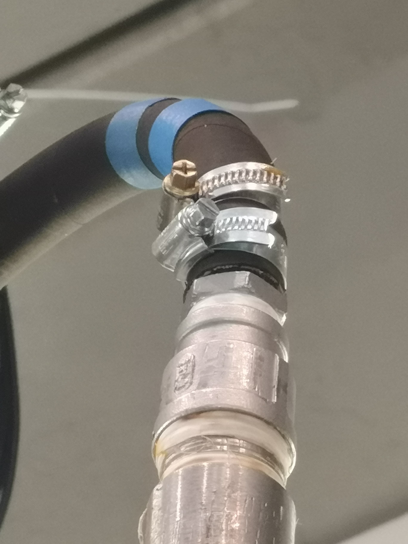
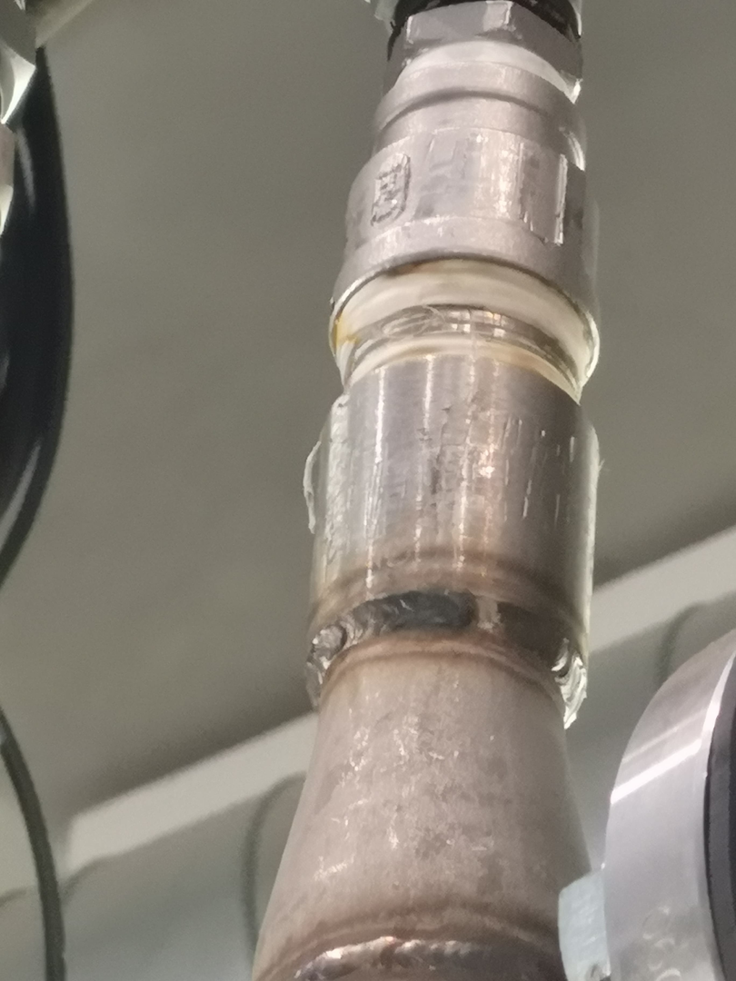
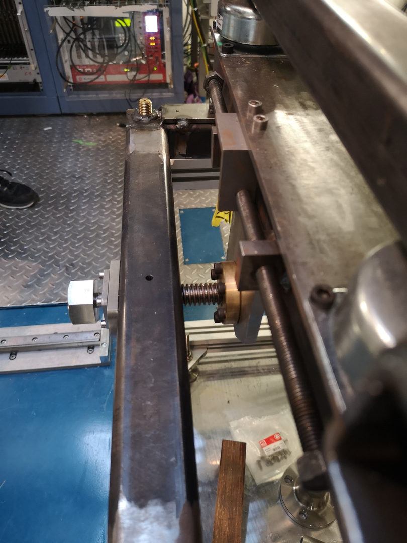
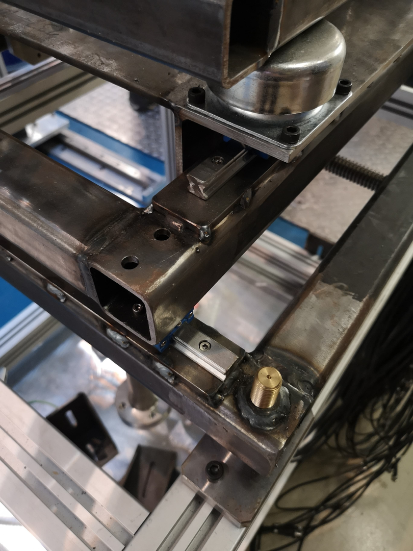
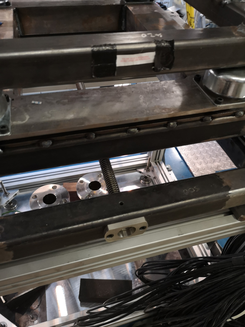
Pictures of leaking cooling pipe

MACB switch settings

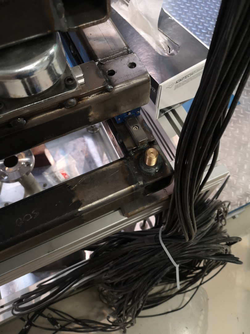
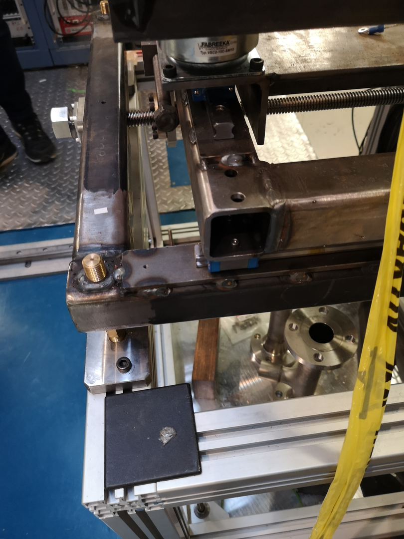
AIDA mount - needs rotated

Attachment 11 - AIDA@DESPEC MACB settings - 100MHz and WR |
| Attachment 1: 50652032_353136001936813_367180692620050432_n.jpg
|

|
| Attachment 2: 50964908_1044865512372636_8341768864786284544_n.jpg
|
|
| Attachment 3: 50724736_354107018511390_7832758890239361024_n.jpg
|
|
| Attachment 4: 50668223_286084358731841_9104059387265155072_n.jpg
|
|
| Attachment 5: 50628587_236303927288815_6354319211518492672_n.jpg
|
|
| Attachment 6: 50487774_2016311125120229_9062406111528747008_n.jpg
|
|
| Attachment 7: 50458306_365278197604681_5981419301792382976_n.jpg
|

|
| Attachment 8: 51007009_2128806710538773_6488480452108615680_n.jpg
|
|
| Attachment 9: 50309962_360783668035351_2721892157555212288_n.jpg
|
|
| Attachment 10: 51087974_2761887407370164_7395929517593722880_n.jpg
|
|
| Attachment 11: despecmacb.pdf
|

|
|
|
292
|
Tue May 4 14:05:48 2021 |
NH | MACB Cables |
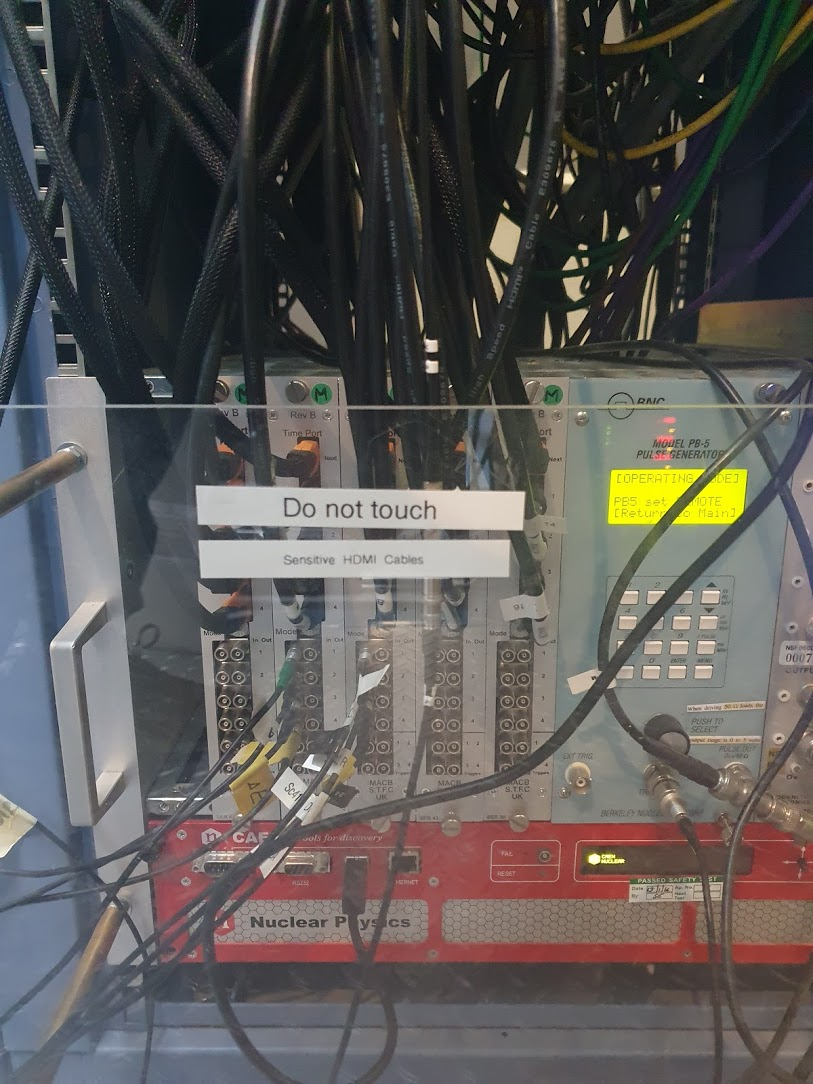
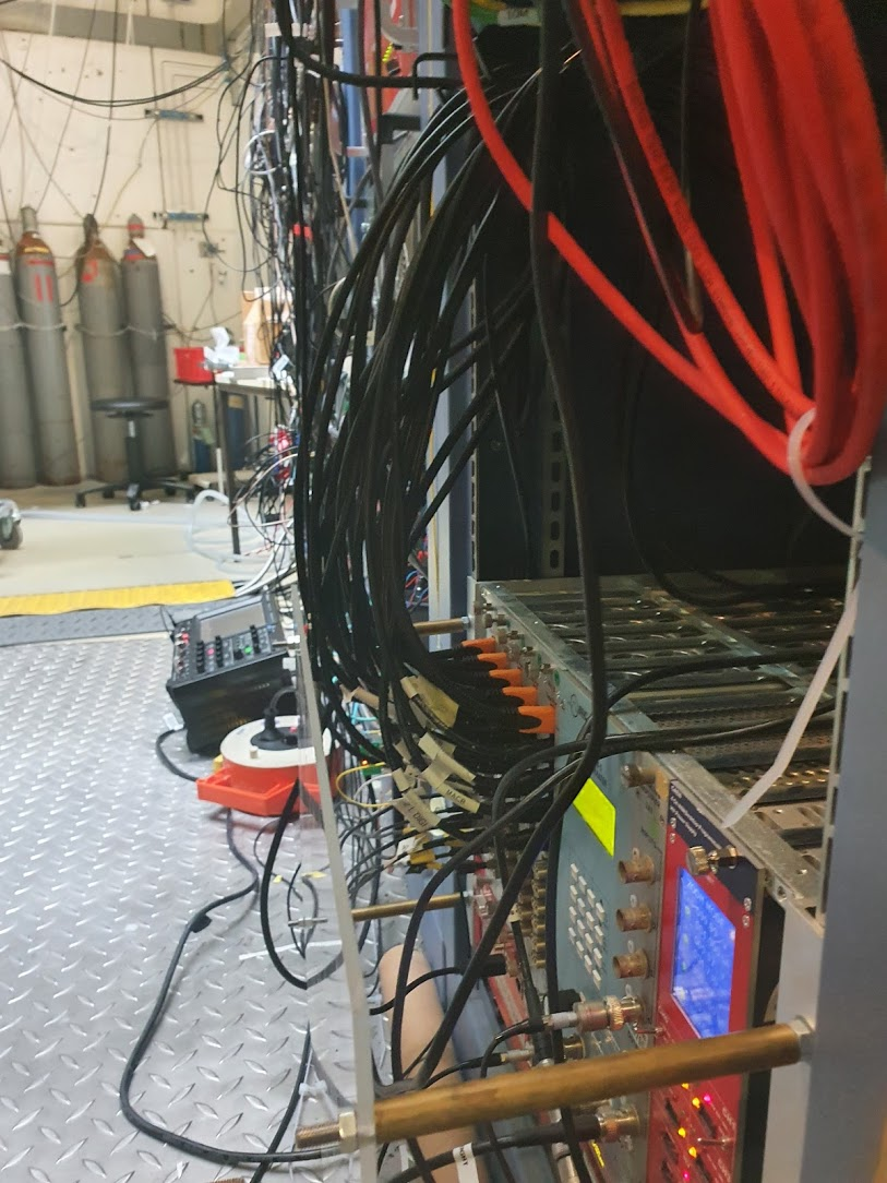
During the installation of the 4 new HDMI cables for aidas13-16 the HDMI cables between the MACB Root and the MACB leaves were looped through the cable guide at the top to support them more
This may improve their connection and reduce the chance of WR errors seen in S460/S452
The connectors were all reseated a few times to clean the contacts too |
| Attachment 1: macb_front.jpg
|
|
| Attachment 2: macb_side.jpg
|
|
|
|
435
|
Thu May 12 22:49:39 2022 |
BA, MA | Low Rates |
The rate is very low in all aida, not sure . |
| Attachment 1: RatesLow2022-05-12_23-48-01.png
|

|
|
|
441
|
Fri May 13 06:56:14 2022 |
OH, BA, MA | Low Rates |
| Quote: |
|
The rate is very low in all aida, not sure .
|
This was because the statistics page had been changed to transfer buffers. The rates were ok |
|
|
460
|
Mon May 16 14:07:06 2022 |
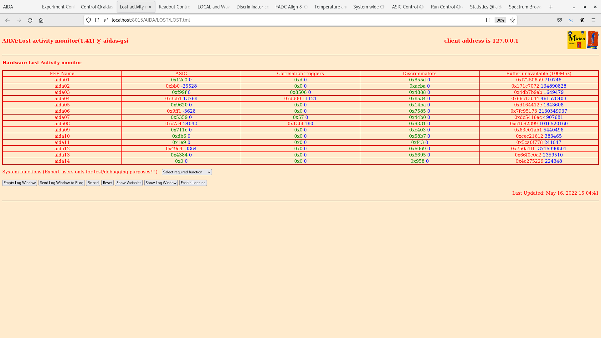
TD | Lost activity monitor |
|
| Attachment 1: Screenshot_from_2022-05-16_15-04-56.png
|
|
|
|
539
|
Fri Mar 15 16:29:57 2024 |
NH | Leakage currents |
The behaviour of the DSSSD leakage current at low voltages and during biases is unusual and varies depending on how the adapter boards are connected
To summarise the behaviour I have observed

Minimum bias configuration:
 4 adapter boards, one n+n (LK1), three p+n (-ve bias), ground from n+n to one p+n
 Voltage (and leakage current) unstable at low voltages, seems to settle at around -60 V
 Drops can include 0 leakage current

Full adapter configuration:
 8 adapter boards, ground ring complete
 Same as minimum, but the drops seem to be much smaller (and not to 0 leakage current)
 -60V again seems to be the turnover to a stable leakage current

In both cases the leakage current during ramping appears basically the same as when settled

Full into FEEs
 8 adapter boards, fully connected to 8 FEEs
 The leakage current is *much* higher during ramp,up to 17 uA near the end. No fluctuations
 Once ramping has finished the current quickly drops back down and settles at the nominal leakage current
 This has been observed in October/December too, it is not new (https://elog.ph.ed.ac.uk/AIDA/910)
 During power up of the FEEs the current sometimes drops briefly (when the ASICs get programmed, I believe)


I think it is related to the ground (more or less current flowing through the HV supply instead of alternate paths?)
It should be kept in mind when testing new detectors to not worry about the detector at low voltages |
|
|
686
|
Thu Jan 9 16:25:51 2025 |
TD | LEC fast comparator threshold too low |
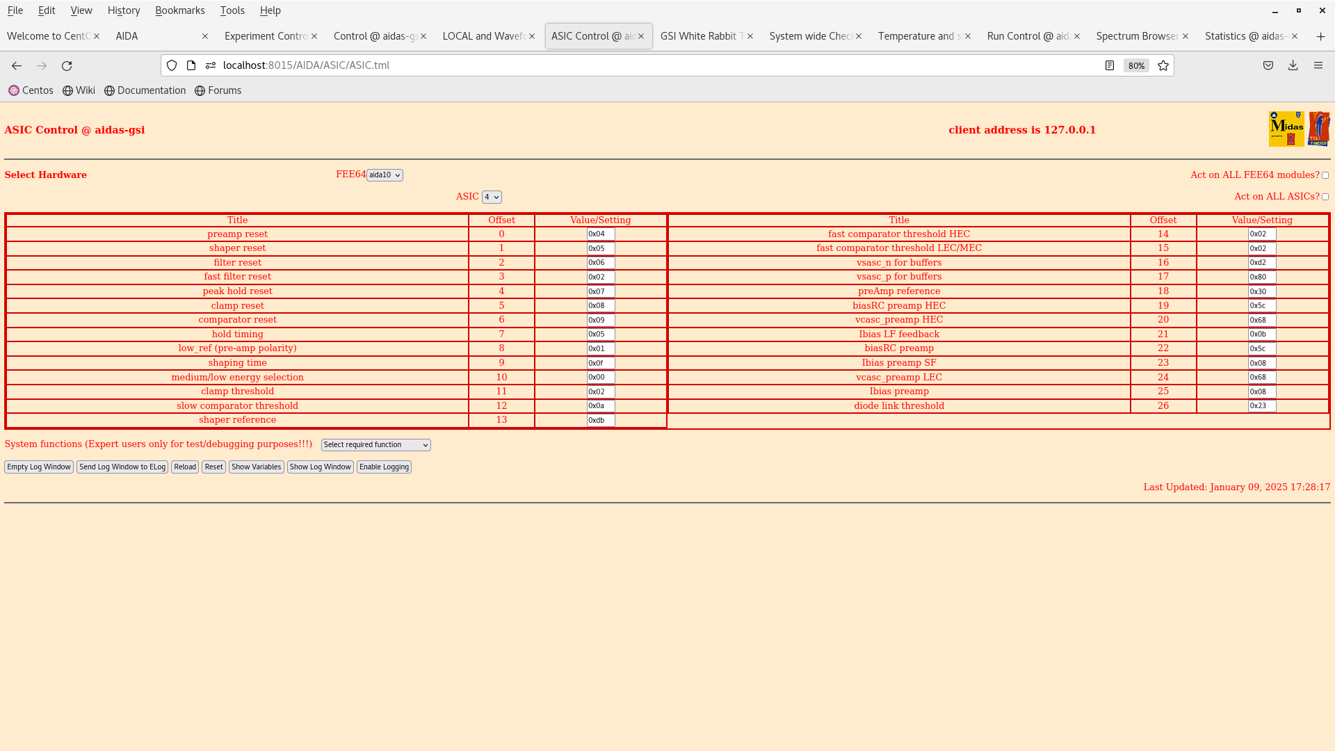
LEC fast comparator has been set to 0x2 (200keV) which is *very* low and means the fast comparator will be triggering on noise.

The *minimum* LEC fast comparator setting should be in the range 0x5 - 0xa (500-1000keV).

I have set the TapeServer to 'no storage' mode to avoid filling the aida-gsi disk with rubbish. |
| Attachment 1: Screenshot_from_2025-01-09_17-28-45.png
|
|
|
|
687
|
Thu Jan 9 17:36:50 2025 |
TD | LEC fast comparator threshold too low |
>
> LEC fast comparator has been set to 0x2 (200keV) which is *very* low and means the fast comparator will be triggering on noise.
>
> The *minimum* LEC fast comparator setting should be in the range 0x5 - 0xa (500-1000keV).
>
> I have set the TapeServer to 'no storage' mode to avoid filling the aida-gsi disk with rubbish.

Thanks. From the DESPEC elog.gsi.de/despec/Implantation+Stack/18

"We have made a trigger from the BGO logic and OR64 of the fast discriminator from AIDA. This was sent as a trigger to the bPlast Exploder.

This did not work as the FEE64s of AIDA are running into high dead-time and a result are dropping data. This is a problem for the ucesb unpacker as it will quite working if one of the subsystem stops sending data. (@Nic is this correct?)

This is indeed what I see as whenever we try to run FAIRROOT the tree builder exits immediately." |
|
|
688
|
Thu Jan 9 17:56:14 2025 |
TD | LEC fast comparator threshold too low |
> >
> > LEC fast comparator has been set to 0x2 (200keV) which is *very* low and means the fast comparator will be triggering on noise.
> >
> > The *minimum* LEC fast comparator setting should be in the range 0x5 - 0xa (500-1000keV).
> >
> > I have set the TapeServer to 'no storage' mode to avoid filling the aida-gsi disk with rubbish.
>
> Thanks. From the DESPEC elog.gsi.de/despec/Implantation+Stack/18
>
> "We have made a trigger from the BGO logic and OR64 of the fast discriminator from AIDA. This was sent as a trigger to the bPlast Exploder.
>
> This did not work as the FEE64s of AIDA are running into high dead-time and a result are dropping data. This is a problem for the ucesb unpacker as it will quite working if one of the subsystem stops sending data. (@Nic is this correct?)
>
> This is indeed what I see as whenever we try to run FAIRROOT the tree builder exits immediately."

We have increased the all thresholds excluding aida10 to 0xff. To not trigger on the other FEEs, however better, the DAQ still occasionally runs into dead time and as such fails with making trees.

We have thus elected to turn off AIDA and move out the platform. The conclusion is that we are not able to do this fast timing test with a 200 keV threshold. |
|
|
689
|
Fri Jan 10 10:03:43 2025 |
TD | LEC fast comparator threshold too low |
> > >
> > > LEC fast comparator has been set to 0x2 (200keV) which is *very* low and means the fast comparator will be triggering on noise.
> > >
> > > The *minimum* LEC fast comparator setting should be in the range 0x5 - 0xa (500-1000keV).
> > >
> > > I have set the TapeServer to 'no storage' mode to avoid filling the aida-gsi disk with rubbish.
> >
> > Thanks. From the DESPEC elog.gsi.de/despec/Implantation+Stack/18
> >
> > "We have made a trigger from the BGO logic and OR64 of the fast discriminator from AIDA. This was sent as a trigger to the bPlast Exploder.
> >
> > This did not work as the FEE64s of AIDA are running into high dead-time and a result are dropping data. This is a problem for the ucesb unpacker as it will quite working if one of the subsystem stops sending
data. (@Nic is this correct?)
> >
> > This is indeed what I see as whenever we try to run FAIRROOT the tree builder exits immediately."
>
> We have increased the all thresholds excluding aida10 to 0xff. To not trigger on the other FEEs, however better, the DAQ still occasionally runs into dead time and as such fails with making trees.
>
> We have thus elected to turn off AIDA and move out the platform. The conclusion is that we are not able to do this fast timing test with a 200 keV threshold.

Per our discussions in December 2024 this is exactly what would be expected. |
|
|
18
|
Thu Jan 24 10:21:26 2019 |
CA, TD, NH, VP | January 24th 2019 |
10.30 AIDA setup and DAQ start complete
      writing to file TapeData/NULL/R1

      FEE64 Temperatures and Good event statistics ok (attachments 1 and 2)

11.00 results of analyser - shows significant number of timewarps in aida07, and a few in aida01-04

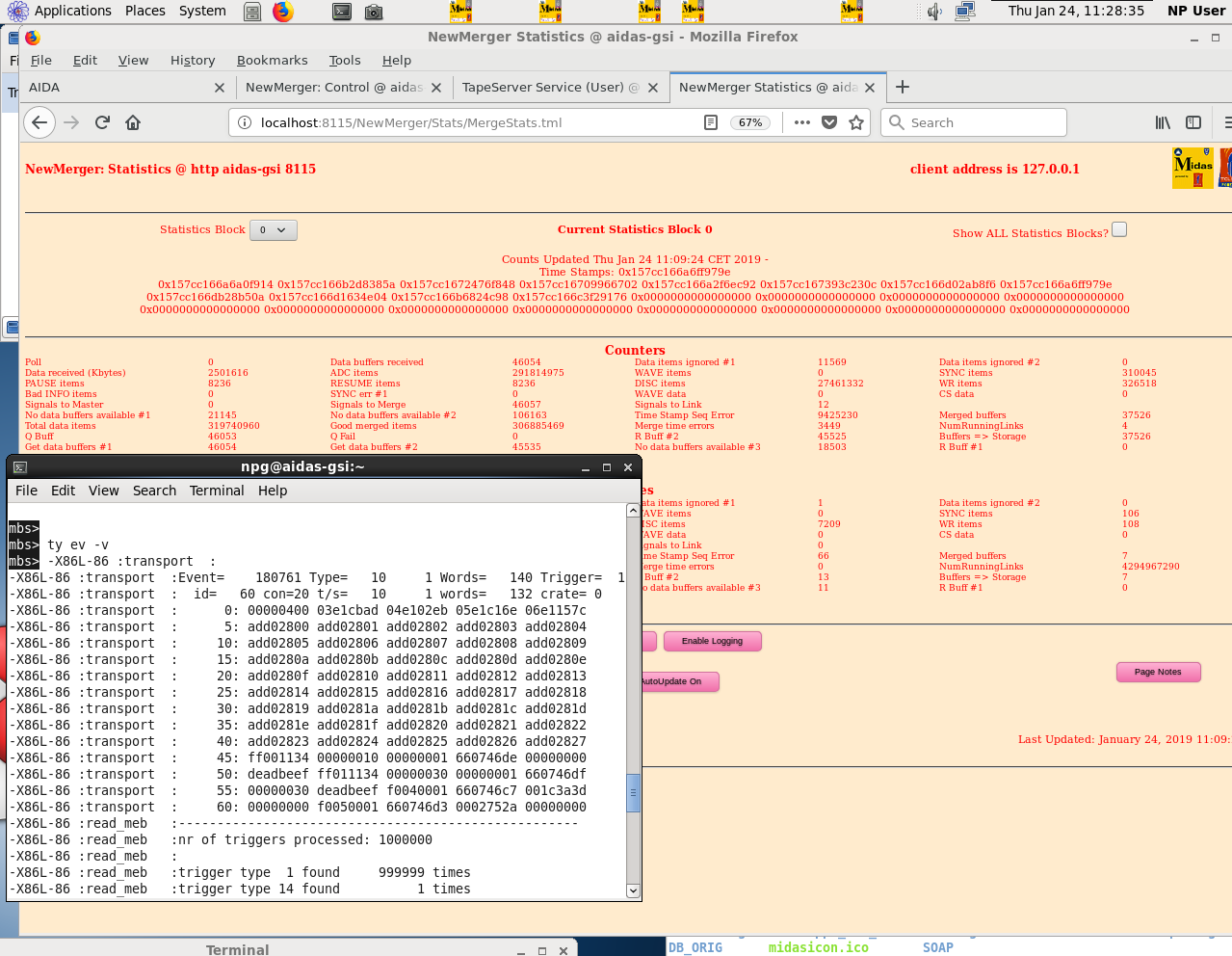
11.24 compared timestamps between mbs and AIDA, agree to 8 digits (attachment 3)

12.49 DAQ and Merger stopped and restarted

      Raised slow comparator threshold from 0xa to 0x64

      Raised fast comparator threshold (LEC/MEC) from 0xf to 0xff

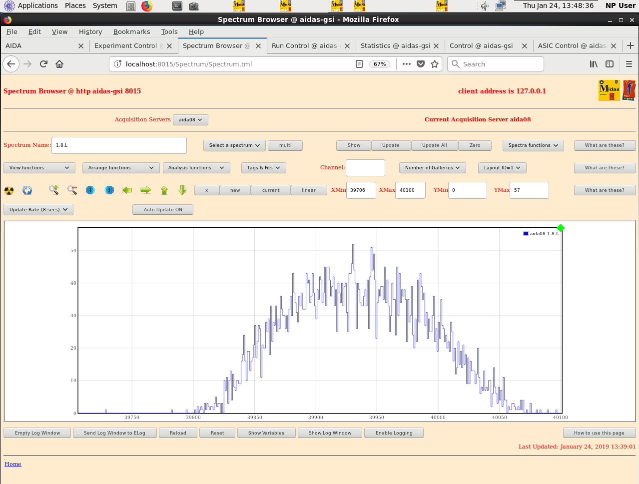
12.51 Good event statistics: aida08 running at a normal rate

      pulser peak (1.8.L) no longer has noise shoulder (attachment 4)

      writing to file TapeData/NULL/R2


13.58 stopped writing to file. Pulser frequency increased to 1 kHz

      writing to file TapeData/NULL/R3

15.00 file R4 - DAQ startup

17.58 trimmed and re-crimped ground wire on aida08
      lowered pulser freq back to 50Hz
      reduced slow comparator threshold to 0xa, fast comparator threshold (LEC) to 0xf

      good event stats ok, aida08 no longer running hot (attachment 6)
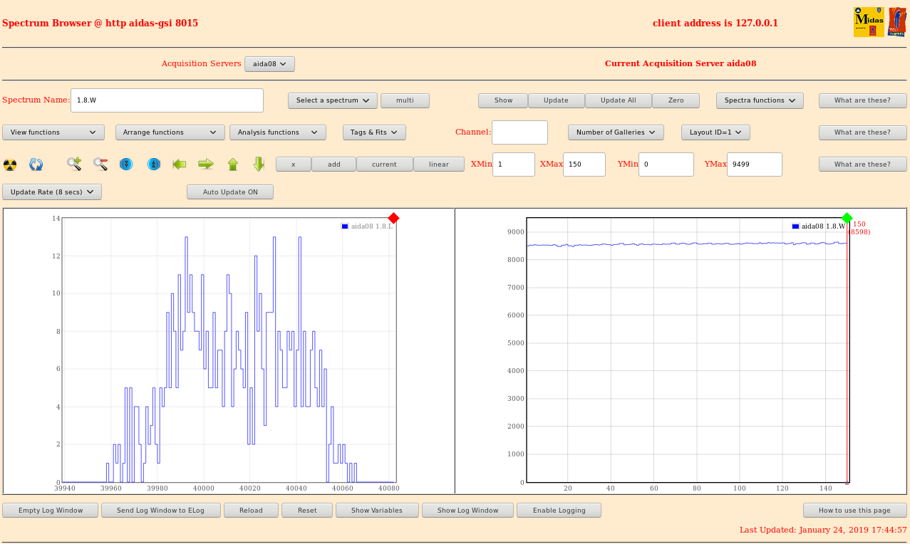
      1.8.L and 1.8.W spectra of aida08 (attachment 5)
      pulser peak width now at 55.71

FEE64 temperatures ok (attachment 7) |
| Attachment 1: 240119_stats.png
|

|
| Attachment 2: 240119_temp.png
|

|
| Attachment 3: 240119_timestamps.png
|
|
| Attachment 4: 240119_fee8_18L.png
|
|
| Attachment 5: 240119_spectra.png
|
|
| Attachment 6: 1740Statsafter240119.png
|

|
| Attachment 7: 240119_tempafter.png
|

|
|
|
17
|
Wed Jan 23 17:03:08 2019 |
CA, TD, NH, VP | January 23rd 2019 |
Post White Rabbit update

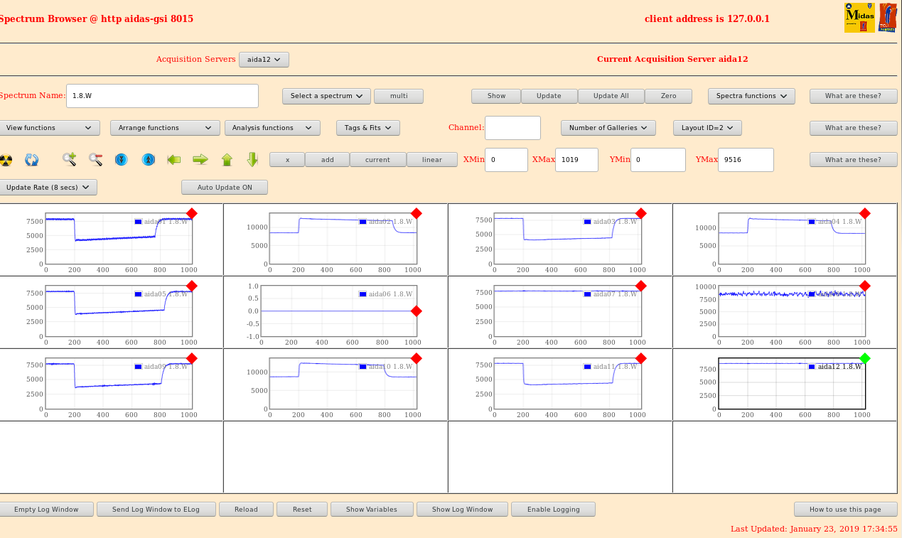
Attachment 1 - 1.8.W pulser waveform spectra for all FEE64
             - pulser signals observed in all FEE64

Attachment 2 - good event statistics - aida08 has significant noise

Attachment 3 - FEE64 temperatures - all ok, but firmware version not displayed

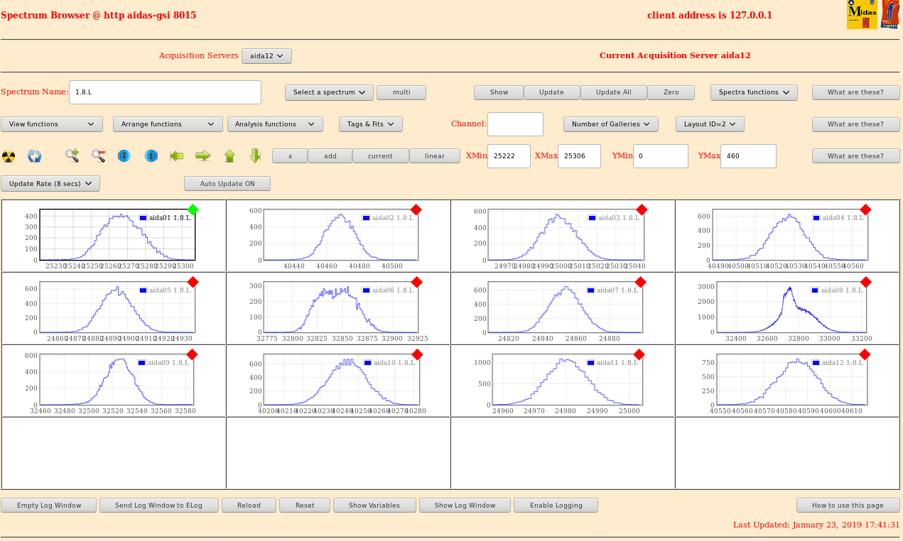
Attachment 4 - 1.8.L pulser peak spectra

             - widths:

             aida01 - 23.66
             aida02 - 19.76
             aida03 - 20.43
             aida04 - 18.82
             aida05 - 20.05
             aida06 - 41.04
             aida07 - 21.24
             aida08 - 205.02 (noisy FEE64)
             aida09 - 24.81
             aida10 - 22.85
             aida11 - 13.98
             aida12 - 19.90

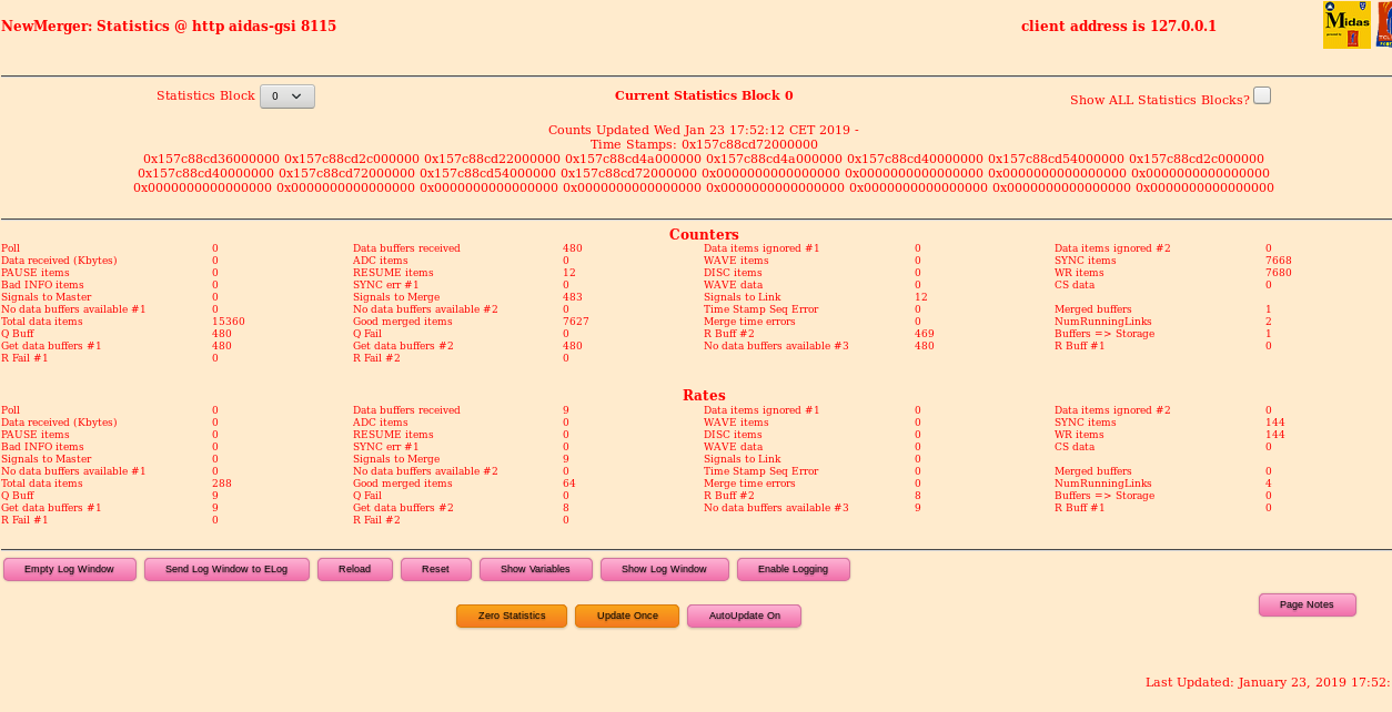
Attachment 5 - New Merger statistics

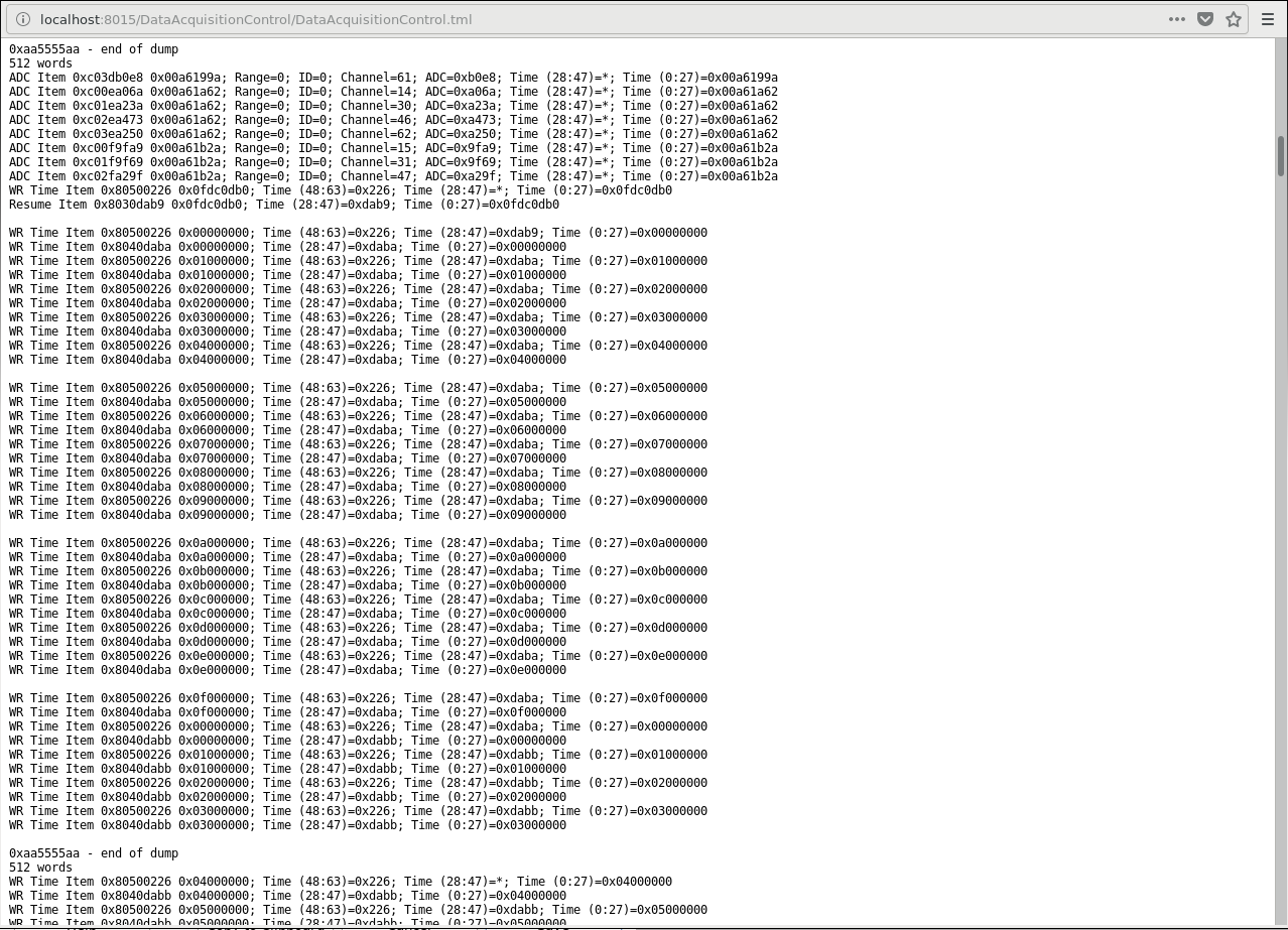
Attachment 6 - Raw data stream |
| Attachment 1: 230119_18W.png
|
|
| Attachment 2: 230119_stats.png
|

|
| Attachment 3: 230119_temp.png
|

|
| Attachment 4: 231019_18L.png
|
|
| Attachment 5: 231019_mergestats.png
|
|
| Attachment 6: 231019_rawdatastream.png
|
|
|
|
15
|
Wed Jan 23 08:12:01 2019 |
CA, TD, NH, VP | January 22nd 2019 |
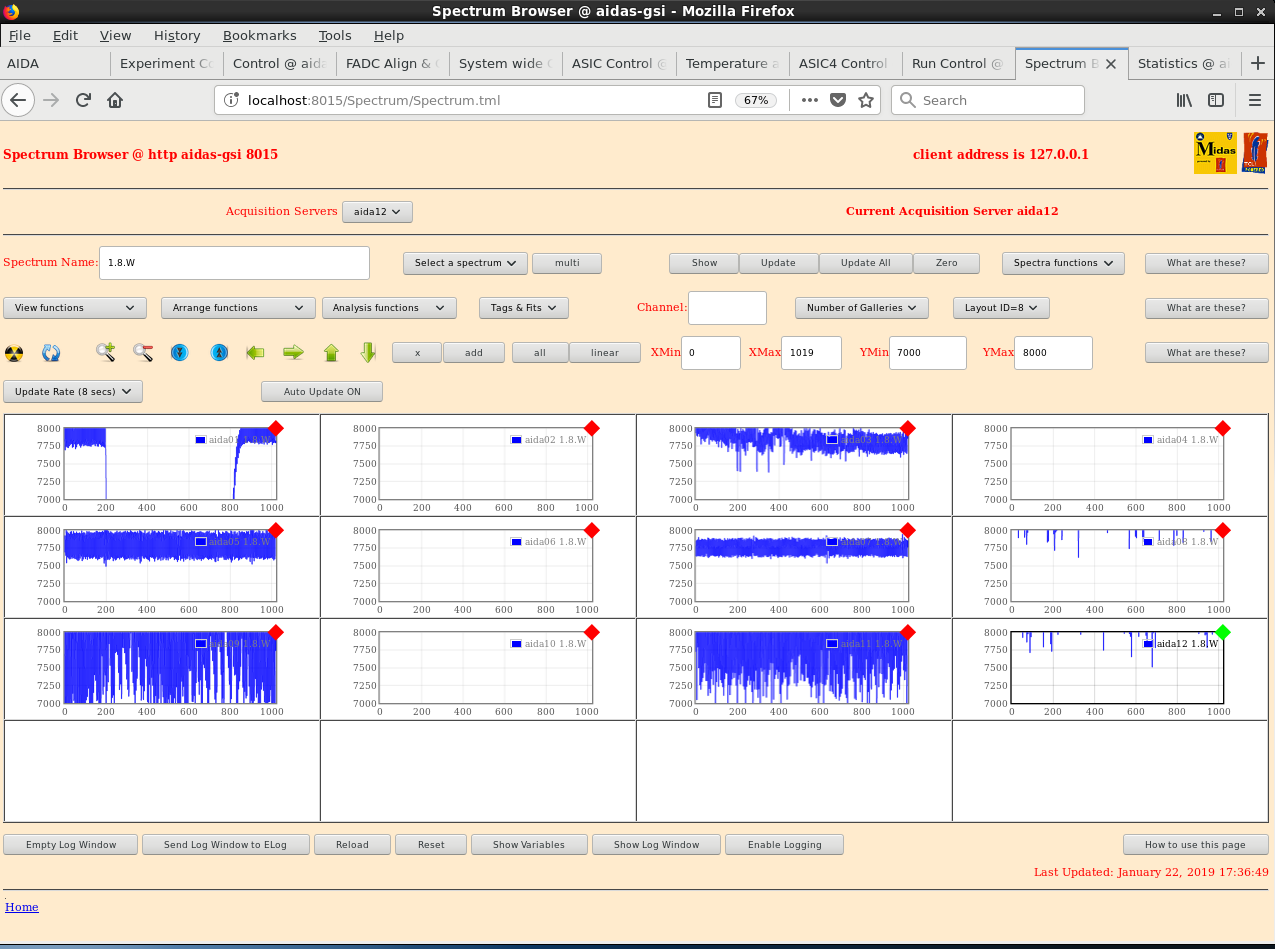
Attachment 1 - 1.8.W waveform spectra with pulser signal

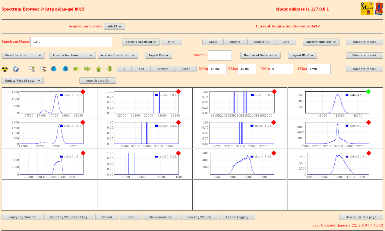
Attachment 2 - 1.8.L pulser peak spectra

widths: aida01 - 16.06

        aida04 - 20.68

        aida05 - 14.03

        aida08 - 73.02

        aida09 - 669.29

        aida11 - 405.35

        aida12 - 397.6

Attachment 3 - good event statistics
               fast comparator threshold (LEC) at 0xff
               FEEs 8,9,11,12 running hot

Attachment 4 - FEE64 temperatures - all ok

System wide checks ok, except aida02 fails ADC calibration

Leak found in seal on cooling pipe, switched power off |
| Attachment 1: 220119_18W.png
|
|
| Attachment 2: 220119_pulserpeaks.png
|
|
| Attachment 3: 220119_stats.png
|

|
| Attachment 4: 220119_Temp.png
|

|
|
|
555
|
Tue Apr 2 12:36:25 2024 |
JB, CC, NH | Installing FEE64s of DSSSD2 cont. |
Some additional checks
- check 'top hat' electrical isolators are correctly installed at each of the 4x mounting points of the AIDA snout assembly
- check snout is electrically isolated with respect to AIDA support assembly/stand, bPlas PCBs/cabling/ground/drain wires and BB7
- check LK1 installed aida02 or aida04 *and* aida06 or aida08 ( I assume these are the n+n Ohmic FEE64s? )
- check LK3 installed bottom, middle p+n junction FEE64s ( i.e. LK3 installed on 2 of 16 FEE64 adaptor PCBs )
- check FEE64 power cables are paired correctly, e.g. aida02 & aida04, aida01 & aida03 etc. Remember that the numbering of the power cables at the FEE64 PSUs may no longer correspond to which FEE64 is actually connected to that cable
- check test and test - cable daisy chains are removed
- check ground cabling attachment to Lemo 00.250 connectors is tight - they have tendency to loosen with handling
|
|
|
552
|
Wed Mar 27 14:22:35 2024 |
JB, NH | Installing FEE64s of DSSSD2 |
Mounted on frame:
DSSD 1 (Upstream) : 3208-2/3208-5/3208-8
DSSD 2 (Downstream): 3208-3/3208-21/3208-22
Current mapping has been redone for better management.
| AIDA - FEE Mapping |
| DSSSD 1 |
DSSSD2 |
| FEE |
MAC |
FEE |
MAC |
| aida01 |
41:ba:8a |
aida06 |
41:05:15 |
| aida02 |
41:f6:b7 |
aida07 |
41:f6:5a |
| aida03 |
41:d8:21 |
aida08 |
41:d7:cd |
| aida04 |
41:a0:71 |
aida10 |
41:d0:0E |
| aida05 |
41:cf:ac |
aida13 |
41:d8:2b |
| aida09 |
41:ee:10 |
aida14 |
42:0d:15 |
| aida15 |
41:b4:0c |
aida11 |
41:EE:0f |
| aida12 |
41:ba:89 |
aida16 |
41:f6:ed |
Going to try optimising noise now.
DHCP updated
new ASIC settings: 2024Mar27-11.25.32 - 16 FEEs (2,4,6,8 n+n, rest p+n)
New layouts: /home/npg/LayOut/GSI_Triple_S100
New layout.txt
Firmware of aida11 updated from 0xea40704 to 0x3350706
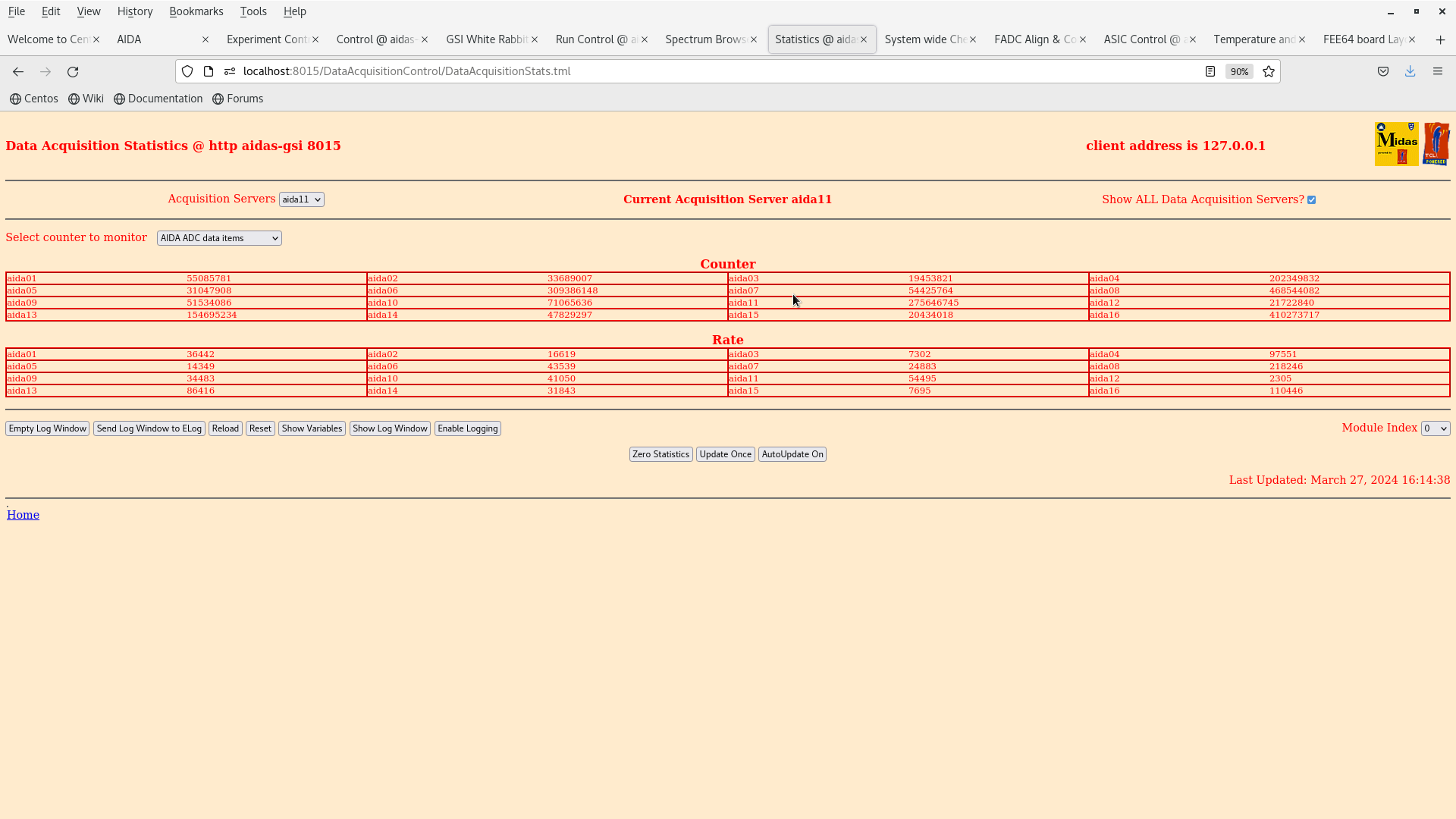
Temps GOOD fig 5
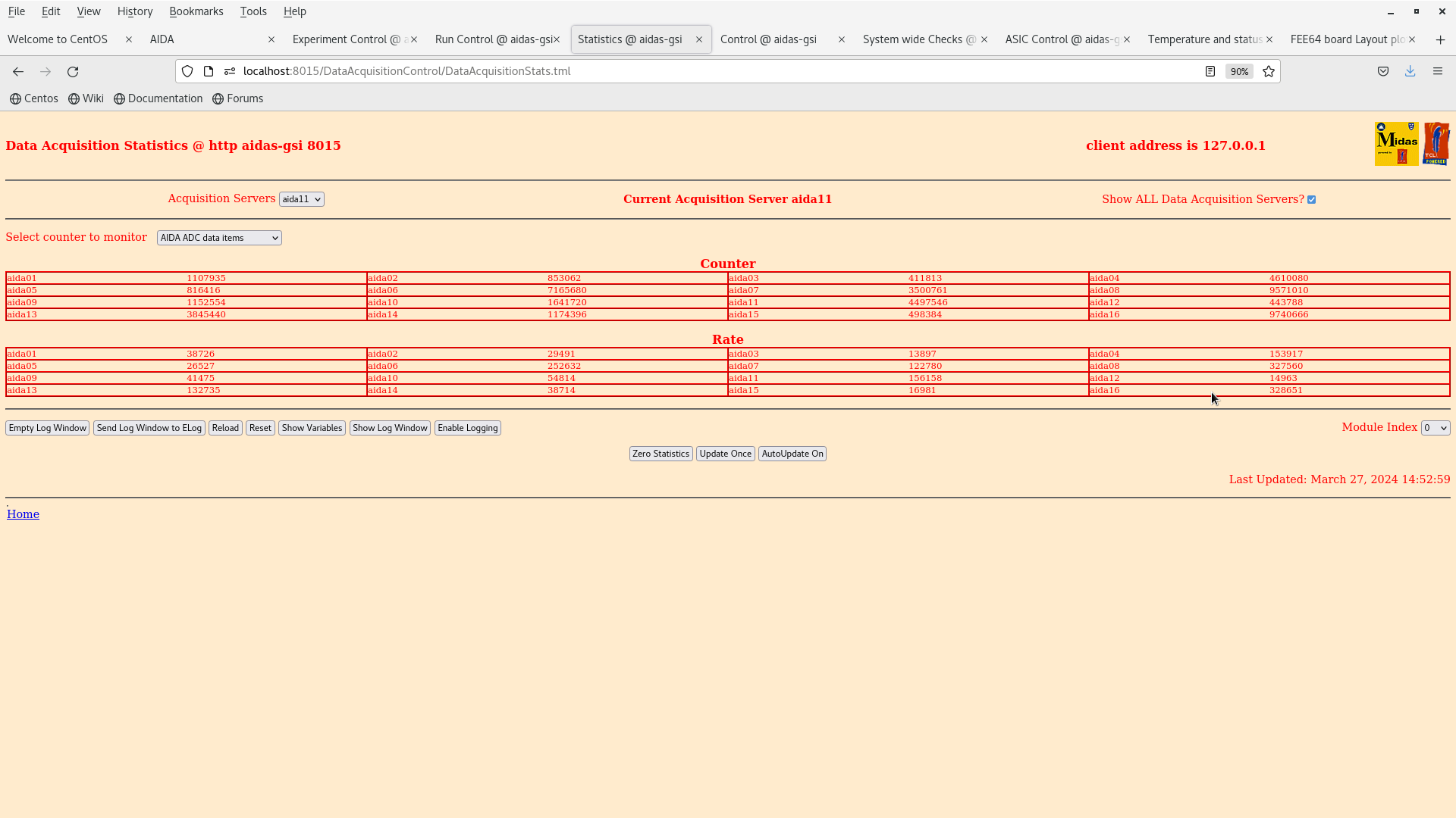
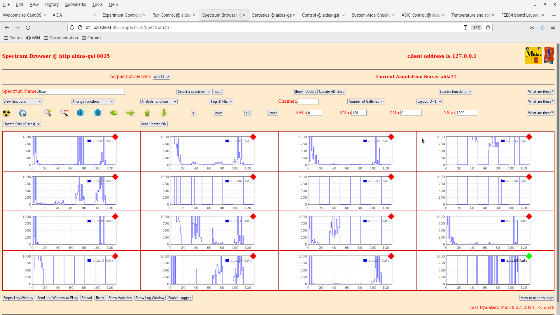
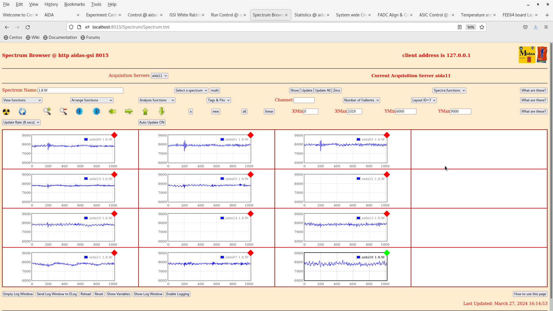
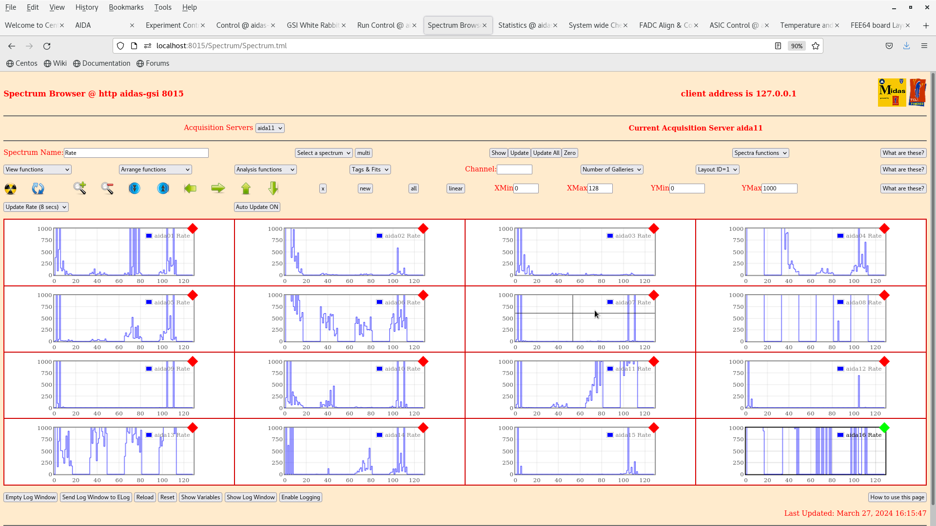
Rates fig 6, 7
Check adapter alignment aida14 and aida16
bPlas left/right cables are not insulated and shorting to the snout
Logs on nnpi1 archived and deleted, start again
All 16 FEEs are showing USB logging connectivity and can be monitored with Pi_Monitor
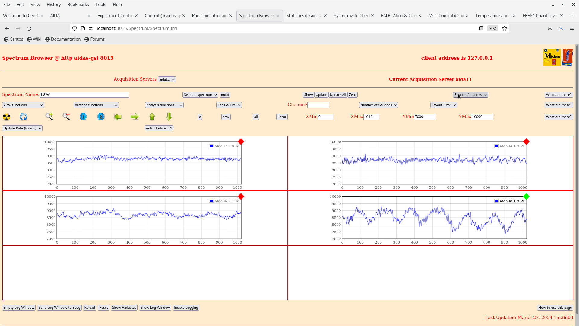
From waveforms aida08 and aida16 are quite unhappy. The rest don't seem too bad. DSSSD 1 is much quieter than it was before!
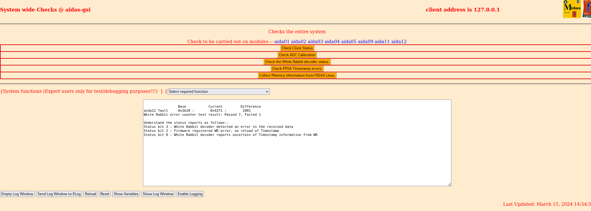
White Rabbit Analysis: aida02 has lots of WR error counter, HDMI reseat needed
aida09-12 have no WR timestamp, the cable to the MACB is bad or the MACB is bad.
Not needed to fix right now (for noise testing)
Turn off bPlas
We see the noise drop a lot |
| Attachment 1: Screenshot_2024-03-15_at_14-41-48_Spectrum_Browser_aidas-gsi.png
|

|
| Attachment 2: Screenshot_2024-03-15_at_14-44-59_Statistics_aidas-gsi.png
|

|
| Attachment 3: Screenshot_2024-03-15_at_14-55-07_System_wide_Checks_aidas-gsi.png
|
|
| Attachment 4: Screenshot_2024-03-15_at_14-57-19_Temperature_and_status_scan_aidas-gsi.png
|

|
| Attachment 5: Screenshot_from_2024-03-27_14-51-12.png
|

|
| Attachment 6: Screenshot_from_2024-03-27_14-53-05.png
|
|
| Attachment 7: Screenshot_from_2024-03-27_14-53-56.png
|
|
| Attachment 8: Screenshot_from_2024-03-27_15-31-10.png
|

|
| Attachment 9: Screenshot_from_2024-03-27_15-35-38.png
|

|
| Attachment 10: Screenshot_from_2024-03-27_15-36-13.png
|
|
| Attachment 11: Screenshot_from_2024-03-27_16-14-44.png
|
|
| Attachment 12: Screenshot_from_2024-03-27_16-15-00.png
|
|
| Attachment 13: Screenshot_from_2024-03-27_16-15-27.png
|

|
| Attachment 14: Screenshot_from_2024-03-27_16-15-56.png
|
|
|
|
553
|
Thu Mar 28 09:18:53 2024 |
TD | Installing FEE64s of DSSSD2 |
Some additional checks
- check 'top hat' electrical isolators are correctly installed at each of the 4x mounting points of the AIDA snout assembly
- check snout is electrically isolated with respect to AIDA support assembly/stand, bPlas PCBs/cabling/ground/drain wires and BB7
- check LK1 installed aida02 or aida04 *and* aida06 or aida08 ( I assume these are the n+n Ohmic FEE64s? )
- check LK3 installed bottom, middle p+n junction FEE64s ( i.e. LK3 installed on 2 of 16 FEE64 adaptor PCBs )
- check FEE64 power cables are paired correctly, e.g. aida02 & aida04, aida01 & aida03 etc. Remember that the numbering of the power cables at the FEE64 PSUs may no longer correspond to which FEE64 is actually connected to that cable
- check test and test - cable daisy chains are removed
- check ground cabling attachment to Lemo 00.250 connectors is tight - they have tendency to loosen with handling
| Quote: |
|
Mounted on frame:
DSSD 1 (Upstream) : 3208-2/3208-5/3208-8
DSSD 2 (Downstream): 3208-3/3208-21/3208-22
Current mapping has been redone for better management.
| AIDA - FEE Mapping |
| DSSSD 1 |
DSSSD2 |
| FEE |
MAC |
FEE |
MAC |
| aida01 |
41:ba:8a |
aida06 |
41:05:15 |
| aida02 |
41:f6:b7 |
aida07 |
41:f6:5a |
| aida03 |
41:d8:21 |
aida08 |
41:d7:cd |
| aida04 |
41:a0:71 |
aida10 |
41:d0:0E |
| aida05 |
41:cf:ac |
aida13 |
41:d8:2b |
| aida09 |
41:ee:10 |
aida14 |
42:0d:15 |
| aida15 |
41:b4:0c |
aida11 |
41:EE:0f |
| aida12 |
41:ba:89 |
aida16 |
41:f6:ed |
Going to try optimising noise now.
DHCP updated
new ASIC settings: 2024Mar27-11.25.32 - 16 FEEs (2,4,6,8 n+n, rest p+n)
New layouts: /home/npg/LayOut/GSI_Triple_S100
New layout.txt
Firmware of aida11 updated from 0xea40704 to 0x3350706
Temps GOOD fig 5
Rates fig 6, 7
Check adapter alignment aida14 and aida16
bPlas left/right cables are not insulated and shorting to the snout
Logs on nnpi1 archived and deleted, start again
All 16 FEEs are showing USB logging connectivity and can be monitored with Pi_Monitor
From waveforms aida08 and aida16 are quite unhappy. The rest don't seem too bad. DSSSD 1 is much quieter than it was before!
White Rabbit Analysis: aida02 has lots of WR error counter, HDMI reseat needed
aida09-12 have no WR timestamp, the cable to the MACB is bad or the MACB is bad.
Not needed to fix right now (for noise testing)
Turn off bPlas
We see the noise drop a lot
|
|
|
|
106
|
Wed Dec 11 10:58:52 2019 |
NH | Initital Dec. Analysis |
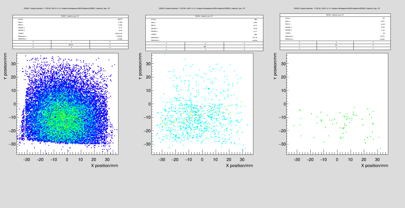
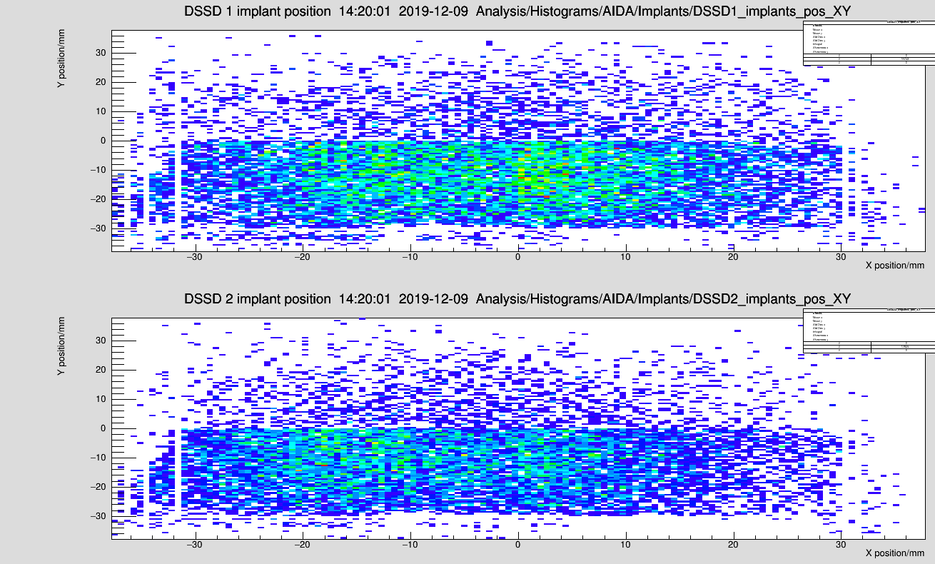
Fig 1: 2D hit pattern of each AIDA DSSD for MBS run 24 (40Ar primary beam, centred)

Low statistics in DSSD2 partly due to low energy deposition

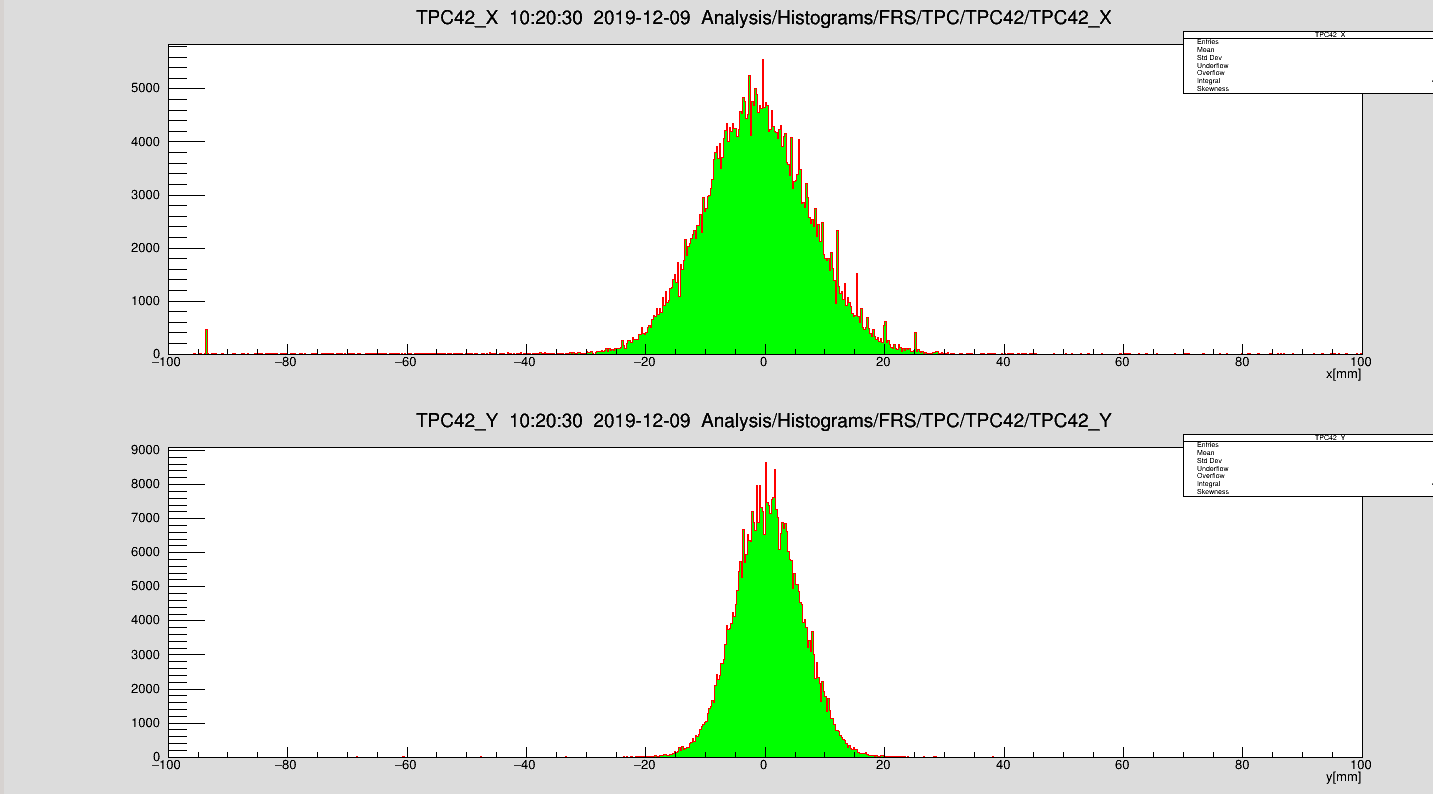
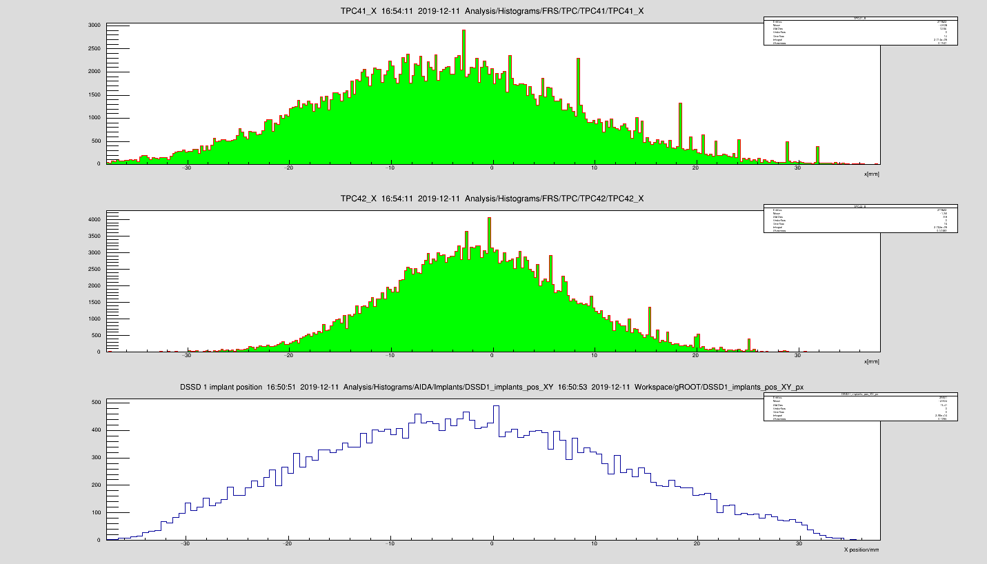
Fig 2: Position according to TPC42 (ca. 2 metres before AIDA)

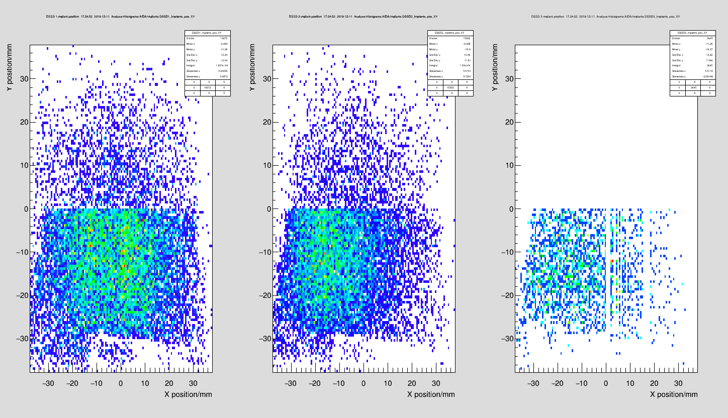
Fig 3: 2D hit pattern of DSSD 1 for MBS run 37 (34Si fragments, no PID gate)

-
Bottom part of AIDA noticably cut off - rotation in DSSD also noticed (not an issue)

Snout was investigated and platform was discovered to not be fully level by Bogdan using a laser level - he has adjusted it so that the AIDA snout is now level to within 1 mm.
(The beam right side was previous 4-6mm below the beam left side)

Y cut in fragment run is currently of unknown origin. Optics are being investigated

-

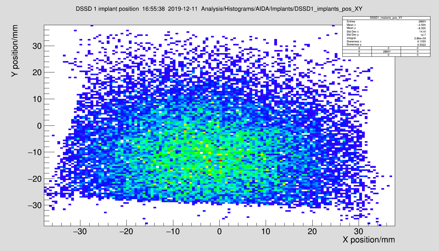
Fig 4: Hit pattern of 40Ar with strip offsets fixed (no missing strips)

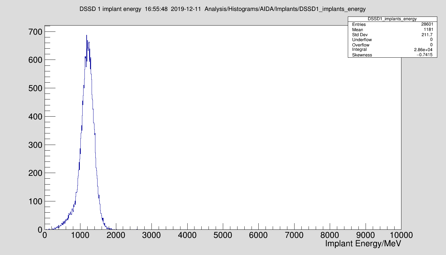
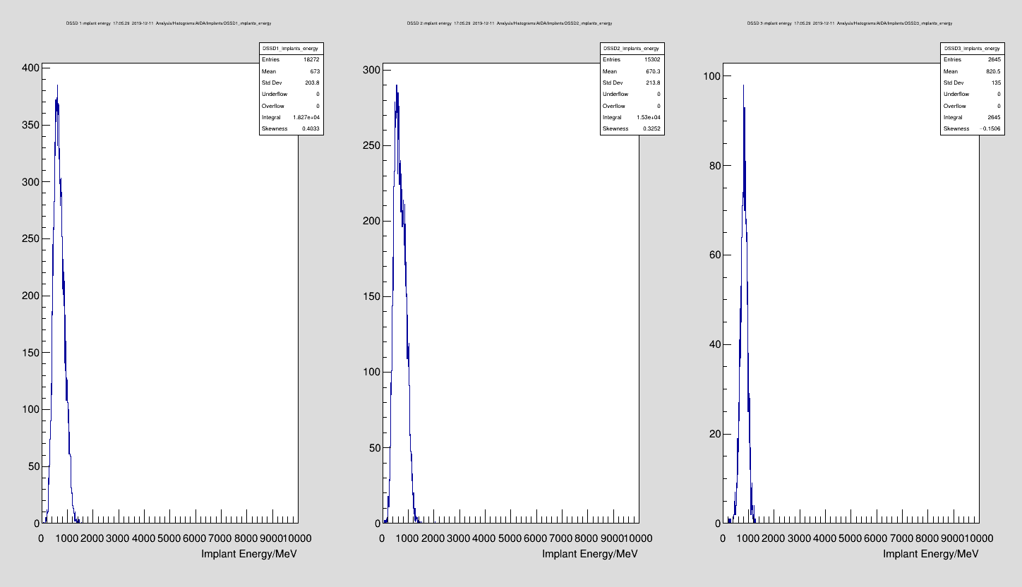
Fig 5: Energy loss in DSSD1 of 40Ar primary beam

Fig 6: TPC 41, TPC 42, AIDA X comparison

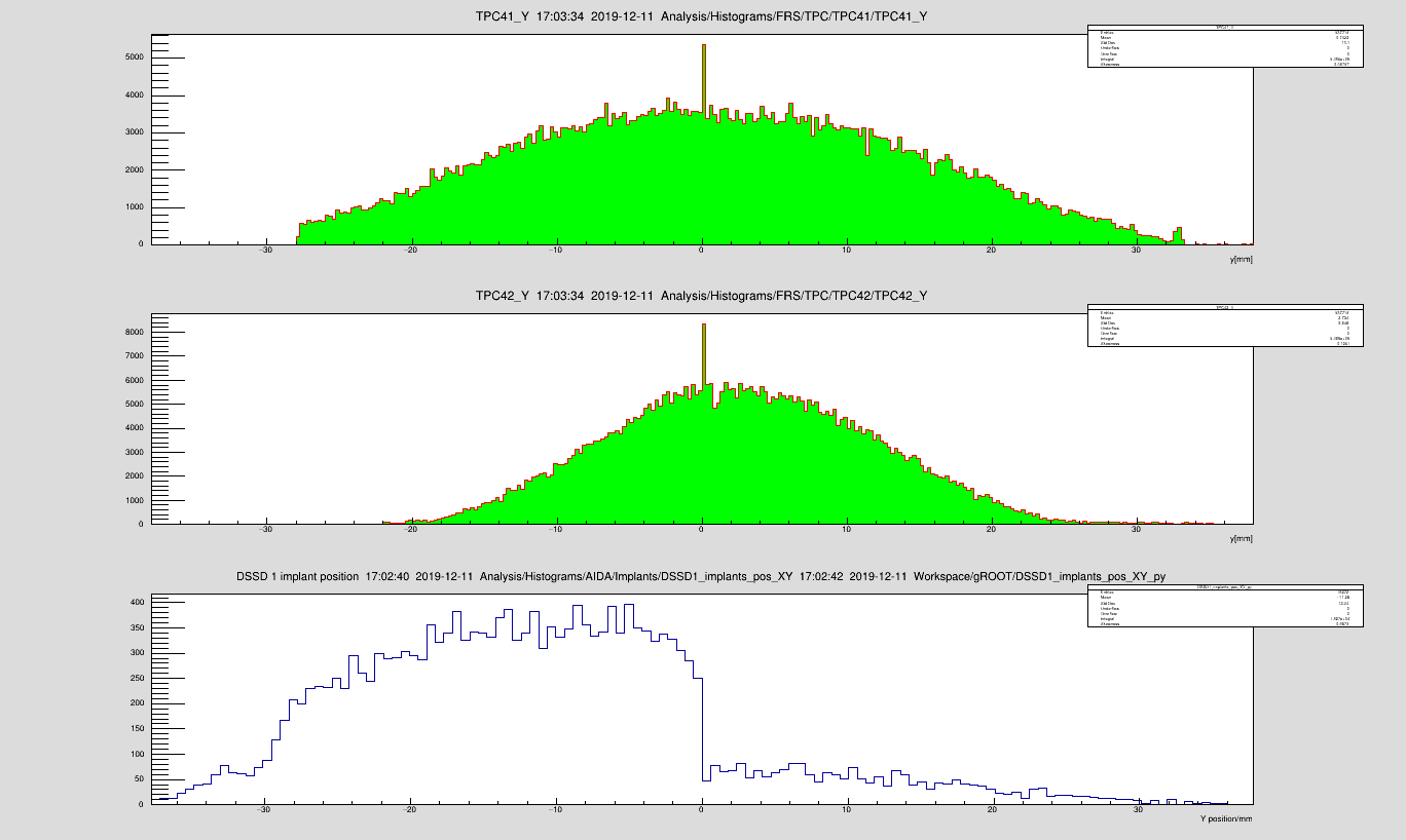
Fig 7: " Y comparison

Fig 8-11: As above for 34Si run

Y cut unknown still.


Statistics of 40Ar file
======================================
AIDA Unpacker Analysis
--------------------------------------
First event: Fri Dec  6 05:21:42 2019
Last event : Fri Dec  6 05:26:17 2019
Duration   : 274.604 seconds
--------------------------------------
MBS Events   (M): 131808426 (481 kHz)
AIDA Words   (W): 110608065 (403 kHz)
ADC Words    (A): 36869349 (134 kHz)
ADC Decays   (D): 36782621 (134 kHz)
ADC Implants (I):    86728 (316 Hz)
Info Words   (F): 73738716 (269 kHz)
SYNC48 Words (S): 36869354 (134 kHz)
SYNC63 Words (s): 36869354 (134 kHz)
PAUSE Words  (P):        4 (0 Hz)
RESUME Words (R):        4 (0 Hz)
Discrim Words(D):        0 (0 Hz)
Unknown Words(U):        0 (0 Hz)
Timewarps    (T):        0 (0 Hz)
Dead Time    (X): 0.113631 s (0.0413799%)
======================================
======================================
Individual FEE Overview
======================================
 FEE |        W        A        D        I        F        S        s    P    R    D    U    T        X
   1 |  4383018  1461006  1439401    21605  2922012  1461006  1461006    0    0    0    0    0 0
   2 | 11468351  3822783  3814577     8206  7645568  3822783  3822783    1    1    0    0    0 0.00733666
   3 |  4353624  1451208  1428500    22708  2902416  1451208  1451208    0    0    0    0    0 0
   4 |  8355002  2785000  2755870    29130  5570002  2785001  2785001    0    0    0    0    0 0
   5 |  1133544   377848   376489     1359   755696   377848   377848    0    0    0    0    0 0
   6 |  9617940  3205980  3205767      213  6411960  3205980  3205980    0    0    0    0    0 0
   7 |  4385477  1461825  1460962      863  2923652  1461826  1461826    0    0    0    0    0 0
   8 | 15105135  5035043  5032985     2058 10070092  5035045  5035045    1    1    0    0    0 0.0126429
   9 | 37487211 12495735 12495422      313 24991476 12495736 12495736    2    2    0    0    0 0.0936512
  10 |   110316    36772    36772        0    73544    36772    36772    0    0    0    0    0 0
  11 | 12329904  4109968  4109763      205  8219936  4109968  4109968    0    0    0    0    0 0
  12 |  1878543   626181   626113       68  1252362   626181   626181    0    0    0    0    0 0


Statistics of 34Si file
======================================
AIDA Unpacker Analysis
--------------------------------------
First event: Sat Dec  7 05:20:22 2019
Last event : Sat Dec  7 05:23:51 2019
Duration   : 208.635 seconds
--------------------------------------
MBS Events   (M): 148639738 (714 kHz)
AIDA Words   (W): 132033086 (634 kHz)
ADC Words    (A): 44011024 (211 kHz)
ADC Decays   (D): 43874168 (210 kHz)
ADC Implants (I):   136856 (657 Hz)
Info Words   (F): 88022062 (423 kHz)
SYNC48 Words (S): 44011028 (211 kHz)
SYNC63 Words (s): 44011028 (211 kHz)
PAUSE Words  (P):        3 (0 Hz)
RESUME Words (R):        3 (0 Hz)
Discrim Words(D):        0 (0 Hz)
Unknown Words(U):        0 (0 Hz)
Timewarps    (T):        0 (0 Hz)
Dead Time    (X): 0.0806864 s (0.0386734%)
======================================
======================================
Individual FEE Overview
======================================
 FEE |        W        A        D        I        F        S        s    P    R    D    U    T        X
   1 |  6814953  2271651  2255653    15998  4543302  2271651  2271651    0    0    0    0    0 0
   2 | 14012582  4670860  4668280     2580  9341722  4670860  4670860    1    1    0    0    0 0.0088226
   3 |  7618290  2539430  2523614    15816  5078860  2539430  2539430    0    0    0    0    0 0
   4 |  8928934  2976310  2950380    25930  5952624  2976312  2976312    0    0    0    0    0 0
   5 |  1631415   543805   531957    11848  1087610   543805   543805    0    0    0    0    0 0
   6 | 10908021  3636007  3633830     2177  7272014  3636007  3636007    0    0    0    0    0 0
   7 |  5644296  1881432  1864053    17379  3762864  1881432  1881432    0    0    0    0    0 0
   8 | 14863755  4954585  4931620    22965  9909170  4954585  4954585    0    0    0    0    0 0
   9 | 36745143 12248379 12244135     4244 24496764 12248380 12248380    2    2    0    0    0 0.0718638
  10 |   198573    66191    66191        0   132382    66191    66191    0    0    0    0    0 0
  11 | 15101900  5033966  5018830    15136 10067934  5033967  5033967    0    0    0    0    0 0
  12 |  9565224  3188408  3185625     2783  6376816  3188408  3188408    0    0    0    0    0 0

All good (no deadtime issues) |
| Attachment 1: AIDA_HitDec19.png
|
|
| Attachment 2: TPCs.png
|
|
| Attachment 3: AIDA-fragments.png
|
|
| Attachment 4: AIDA_XY.png
|
|
| Attachment 5: AIDA_E.png
|
|
| Attachment 6: TPC_41_42_AIDA_X.png
|
|
| Attachment 7: TPC_41_42_AIDA_Y.png
|

|
| Attachment 8: AIDA_XY_34Si.png
|
|
| Attachment 9: AIDA_E_34Si.png
|
|
| Attachment 10: TPC_41_42_AIDA_X_34Si.png
|

|
| Attachment 11: TPC_41_42_AIDA_Y_34Si.png
|
|
|
|
227
|
Fri Apr 16 02:15:12 2021 |
NH | Implants/Punchthrough |
Rate with beam < 1000 Hz still

Not Uranium but some fragments possibly produced in the thick 9g degrader
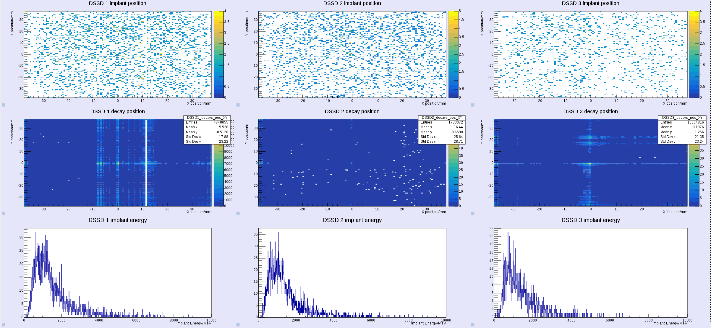
S4 slits are +/- 20mm but these punchthrough and cover the +/- 40mm of AIDA |
| Attachment 1: 53_AM.png
|
|