| ID |
Date |
Author |
Subject |
|
48
|
Wed Oct 18 12:14:09 2023 |
Emma Walker | Processing file for EAR-1 with WF applied, Si-30 | Weighting function for Si-30, Au22, Au20 and Sinatgood applied for parasitic and dedicated beams. |
| Attachment 1: Weighting_processing.c
|
/// 23.6.23, 9:30 edit CLW - process also other runlists

// g++ -Wall -O3 -g `root-config --cflags --ldflags --glibs` Process_Si.C -o Process_Si && ./Process_Si

// includes header, and source only in compiled script
#include "/eos/experiment/ntof/codes/TTOFSort/TTOFSort_nTOF.h"
#ifndef __CINT__
#include "/eos/experiment/ntof/codes/TTOFSort/TTOFSort_nTOF.cxx"
#endif
// --------------------------------------------------------------------------
//
//
//
// --------------------------------------------------------------------------

Double_t a2e_c6d61(Double_t x) {  // from amplitude (channel) to MeV
   return (3.71330E-02+ 2.78468E-04* x );
}
Double_t a2e_c6d62(Double_t x) {  // from amplitude (channel) to MeV
   return (1.21071E-02+ 2.82656E-04* x);
}
Double_t a2e_c6d63(Double_t x) {  // from amplitude (channel) to MeV
   return (2.74746E-02+ 2.64094E-04* x);
}
Double_t a2e_c6d64(Double_t x) {  // from amplitude (channel) to MeV
   return (2.96214E-02+ 2.73633E-04* x );
}

Double_t wf_Si(Double_t x) { //WF for silicon 30
  return (9.65464 - 6.83768 * x + 26.4596 * x * x - 5.02546 * x * x * x + 0.372149 * x * x * x * x);
}

Double_t wf_Sinatgood(Double_t x) { //WF for silicon natural
  return (8.86824 - 1.26346 * x + 18.4828 * x * x - 2.25899 * x * x * x + 0.106017 * x * x * x * x);
}

Double_t wf_Au20(Double_t x) { //WF for 20mm-gold
  return (7.93383 + 1.02633 * x + 16.9180 * x * x - 1.95645 * x * x * x + 0.0918222 * x * x * x * x);
}

Double_t wf_Au22(Double_t x) { //WF for 22mm-gold
  return (7.93673 + 1.00093 * x + 16.9408 * x * x - 1.96542 * x * x * x + 0.0923510 * x * x * x * x);
}

int main() {

    Char_t prefix[] = "/eos/experiment/ntof/processing/official/done/run";
    Char_t suffix[] = ".root";

    Int_t runlist_co[] = {116215, 116216, 116217, 116218, -1};

    Int_t runlist_ba[] = {116208, 116209, 116210, 116211, 116212, 116213, 116214, -1};

    Int_t runlist_mn[] = {116203, 116204, 116205, 116206, 116207, -1};

    Int_t runlist_bi[] = {116193, 116194, -1};

    Int_t runlist_cs[] = {116093, 116159, 116160, 116161, 116296, 116384, 116385,116445,116476,116567 ,-1};

    Int_t runlist_y[] = {116094, 116162, 116163, 116164, 116297, 116298, 116380, 116381, 116382,116446,116475,116568, -1};

    Int_t runlist_ambe[] = {116095, 116096, 116097, 116165, 116166, 116167, 116168, 116169, 116170, 116171, 116172, 116173, 116174, 116299, 116301, 116302, 116375, 116376,116467,116468,116469,116470,116569 ,116570,116571,-1};

    Int_t runlist_cmc[] = {116179, 116180, 116181, 116182, 116183, 116184, 116185, 116186, 116187, 116188, 116189, 116190, 116191, 116192, 116219, 116220, 116221, 116222, 116303, 116304, 116305, 116377,116378, 116379,116447,116448, 116449,116450, 116451,116471,116472,116473,116474, -1};

    Int_t runlist_cnat[]={116284, 116285, 116286, 116287, 116288, 116308, 116309, 116310, 116311,
116312,116313,116314,116315,116316,116317,116318,116319,116320, -1};

    Int_t runlist_au20mm[] = {116100, 116101, 116102,116322,116548, -1};

    Int_t runlist_au22mm[] = { 116226, 116227, 116229, 116231, 116232, 116234, 116235, 116321,116507,116508,116509,116510,-1};
    //116225 116505 116506was 'BAD'
    Int_t runlist_amb[] = {116103, 116104, 116106, 116108, 116109, 116110, 116111, 116119, 116120, 116121, 116122, 116123, 116127, 116128, 116129, 116130, 116131, 116132, 116133, 116134, 116135, 116141, 116143, 116154, 116155, 116156, 116157, 116158, 116175, 116176, 116177, 116178,116197, 116198, 116199, 116200, 116201, 116202, 116248, 116249, 116250, 116251, 116252, 116253, 116254, 116255, 116257, 116258, 116259,116374, 116386, 116387, 116388, 116389, 116390, 116391, 116392, 116393,116405,116444,116443,116452,116453,116454,116455,116456,116457,116458,116459,116460,116461,116462,116463,116464,116465,116466,116477,116478,116479,116480,116481,116483,116485,116487,116488,116490,116491,116492,116493,116494,116495,116496,116498,116499,116501,116503,116519,116520,116521,116522, -1};  // no beam and no calibration source

    Int_t runlist_dummy[] = {116237, 116241, 116242, 116243, 116244, 116245, 116246, 116247, 116253, 116260, 116261, 116420, 116421, 116422, 116423, 116424, 116425, 116426, 116427, 116428, 116429, 116430, 116431, 116432, 116433, 116434, 116435, 116436, 116437, 116438,116439,-1};
    //, 116418 too slow 116240 is bad
     Int_t runlist_empty[] = {116323, 116324, 116325,116326,116327,116328, -1};

    Int_t runlist_30si[] = {116105, 116112, 116113, 116114, 116115, 116116, 116117, 116118, 116124, 116125, 116126, 116136, 116137, 116138, 116139, 116140, 116142, 116144, 116145, 116146, 116147, 116148, 116149, 116150, 116151, 116152, 116153, 116263, 116264, 116265, 116266, 116268, 116269, 116270, 116271, 116272, 116273, 116274, 116275, 116276, 116277, 116278, 116279, 116280, 116281, 116282, 116283, 116358, 116359, 116360, 116361, 116362, 116363, 116364, 116367, 116368, 116369, 116371, 116372, 116373, 116394, 116395, 116396, 116397, 116398, 116399, 116400, 116401, 116402, 116403, 116404, 116406, 116407, 116408, 116409, 116411, 116412, 116413, 116415,116440,116441,116482,116484,116486,116489,116502,116504, -1};
    //116365, 116466 are empty (should be Si run) , 116370,116442,116414 (116262 this one was 'bad')
    Int_t runlist_sinat[] = {116330, 116331, 116332, 116333, 116335, 116337, 116339, 116341, 116342, 116343, 116344, 116345, 116346, 116347, 116348, 116349, 116350, 116351, 116352, 116353, 116354, 116355, 116356, 116357,116511 ,116512 ,116513 ,116514 ,116517 ,116518 ,116523 ,116524 ,116525 ,116526 ,116527 ,116528  ,116532 ,116533 ,116534 ,116535 ,116536 ,116537 ,116538 ,116539 ,116540 ,116541 ,116542 ,116543 ,116544 ,116545 ,116546 ,-1};
    //bad 116529, 116530,116531
    Int_t runlist_sinat_good[] = { 116549 ,116551 ,116552 ,116553 ,116554 ,116555 ,116556 ,116557 ,116558 ,116559 ,116560 ,116561 ,116562,116563,116564,116565,116566, -1 };

    TTOFSort *a = new TTOFSort();

    a->AddDetector(kC6D6, 4);

    //a->SetNewBinParsA(kC6D6, 0.0, 6500, 6500000.0);
    a->SetNewBinParsT(kC6D6, -10.0, 2.0, 1e3, 5000, 1e9); //Double the nbins (10k here becomes 20k bpd spec)

    a->PrintSettings();

    a->SetNewFixedDeadtime(kC6D6, 30.0);//fixed deadtime of 30 ns
    a->SetNewCoincidencetime(kC6D6, 30.0);//Coincidences between 30 ns
    a->SetNewVariableNames_amplitude(kC6D6, "amp");
    a->SetNewBinParsA(kC6D6, 0.0, 6500, 70000);
    a->SetNewCutsAmp_all(kC6D6, 600, 50000);

    a->UseCalibration(kC6D6, a2e_c6d61, a2e_c6d62, a2e_c6d63, a2e_c6d64);
    a->SetNewCutsEg(kC6D6, 0.200, 8.0, 0.200, 8.0, 0.200, 8.0, 0.200, 8.0);

    a->SetPriorCut(kC6D6, "PulseIntensity<1e7");

    //a->ProcessListOfRuns_Sum(prefix, runlist_co, suffix, "Sum_Cal.root", "Co", "RECREATE");
    //a->ProcessListOfRuns_Sum(prefix, runlist_bi, suffix, "Sum_Cal.root", "Bi", "UPDATE");
    //a->ProcessListOfRuns_Sum(prefix, runlist_ba, suffix, "Sum_Cal.root", "Ba", "UPDATE");
    //a->ProcessListOfRuns_Sum(prefix, runlist_mn, suffix, "Sum_Cal.root", "Mn", "UPDATE");
    //a->ProcessListOfRuns_Sum(prefix, runlist_cs, suffix, "Sum_Cal.root", "Cs", "UPDATE");
    //a->ProcessListOfRuns_Sum(prefix, runlist_y, suffix, "Sum_Cal.root", "Y", "UPDATE");
    //a->ProcessListOfRuns_Sum(prefix, runlist_ambe, suffix, "Sum_Cal.root", "Ambe", "UPDATE");
    //a->ProcessListOfRuns_Sum(prefix, runlist_cmc, suffix, "Sum_Cal.root", "Cmc", "UPDATE");
    //a->ProcessListOfRuns_Sum(prefix, runlist_amb, suffix, "Sum_Amb.root", "Amb", "RECREATE");


    //a->ProcessListOfRuns_Single(prefix, runlist_co, suffix, "Co.root", "Co", "RECREATE");
    //a->ProcessListOfRuns_Single(prefix, runlist_bi, suffix, "Bi.root", "Bi", "RECREATE");
    //a->ProcessListOfRuns_Single(prefix, runlist_ba, suffix, "Ba.root", "Ba", "RECREATE");
    //a->ProcessListOfRuns_Single(prefix, runlist_mn, suffix, "Mn.root", "Mn", "RECREATE");
    //a->ProcessListOfRuns_Single(prefix, runlist_cs, suffix, "Cs.root", "Cs", "RECREATE");
    //a->ProcessListOfRuns_Single(prefix, runlist_y, suffix, "Y.root", "Y", "RECREATE");
    //a->ProcessListOfRuns_Single(prefix, runlist_ambe, suffix, "Ambe.root", "Ambe", "RECREATE");
    //a->ProcessListOfRuns_Single(prefix, runlist_cmc, suffix, "Cmc.root", "Cmc", "RECREATE");


    a->UseWeightingFunction(kC6D6, wf_Si);
    a->ProcessListOfRuns_Sum(prefix, runlist_amb, suffix, "Amb_sum_SiWF.root", "Amb", "RECREATE");
    a->UseWeightingFunction(kC6D6, wf_Au20);
    a->ProcessListOfRuns_Sum(prefix, runlist_amb, suffix, "Amb_sum_Au20WF.root", "Amb", "RECREATE");
    a->UseWeightingFunction(kC6D6, wf_Au22);
    a->ProcessListOfRuns_Sum(prefix, runlist_amb, suffix, "Amb_sum_Au22WF.root", "Amb", "RECREATE");
    a->UseWeightingFunction(kC6D6, wf_Sinatgood);
    a->ProcessListOfRuns_Sum(prefix, runlist_amb, suffix, "Amb_sum_SinatgoodWF.root", "Amb", "RECREATE");


    // dedicated >5E12, parasitic 1-5 E12
    //a->SetPriorCut(kC6D6, "PulseIntensity>1e12");
    a->AddDetector(kSILI, 4);
    //a->SetNewBinParsA(kSILI, 0.0, 1e4, 1e5);
    a->SetNewVariableNames_amplitude(kSILI, "amp");
    //a->SetPriorCut(kSILI, "PulseIntensity>1e12");
    a->SetNewBinParsA(kSILI, 0.0, 6500, 70000);
    a->SetNewCutsAmp_all(kSILI, 8000, 40000);
    a->SetNewCutsTime_all(kSILI, 1E4, 1E9);
    a->AddDetector(kPKUP, 1);
    a->SetNewVariableNames_amplitude(kPKUP, "amp");
    a->SetPriorCut(kPKUP,"amp>5000 && amp<50000");
    a->SetNewBinParsA(kPKUP,0.0,6500,70000);
    //a->SetPriorCut(kPKUP, "PulseIntensity>1e12");
    //a->UseWeightingFunction(kC6D6, wf, wf, wf, wf);

    a->SetPriorCut(kC6D6, "PulseIntensity>1e+12");
    a->SetPriorCut(kPKUP, "PulseIntensity>1e+12");
    a->SetPriorCut(kSILI, "PulseIntensity>1e+12");

    //For dedicated pulse
    a->SetPriorCut(kC6D6, "PulseIntensity>5e+12");
    a->SetPriorCut(kSILI, "PulseIntensity>5e+12");
    a->SetPriorCut(kPKUP, "PulseIntensity>5e+12");

    a->UseWeightingFunction(kC6D6, wf_Si);
    a->ProcessListOfRuns_Sum(prefix, runlist_30si, suffix, "Dedicated_Si_weighting.root", "Si", "RECREATE");
    a->ProcessListOfRuns_Sum(prefix, runlist_dummy, suffix, "Dedicated_Si_weighting.root", "Dummy", "UPDATE");
    a->ProcessListOfRuns_Sum(prefix, runlist_cnat, suffix, "Dedicated_Si_weighting.root", "C", "UPDATE");
    a->ProcessListOfRuns_Sum(prefix, runlist_empty, suffix, "Dedicated_Si_weighting.root", "E", "UPDATE");

    a->UseWeightingFunction(kC6D6, wf_Au20);
    a->ProcessListOfRuns_Sum(prefix, runlist_au20mm, suffix, "Dedicated_Au20_weighting.root", "Au20", "RECREATE");
    a->ProcessListOfRuns_Sum(prefix, runlist_dummy, suffix, "Dedicated_Au20_weighting.root", "Dummy", "UPDATE");
    a->ProcessListOfRuns_Sum(prefix, runlist_cnat, suffix, "Dedicated_Au20_weighting.root", "C", "UPDATE");
    a->ProcessListOfRuns_Sum(prefix, runlist_empty, suffix, "Dedicated_Au20_weighting.root", "E", "UPDATE");

    a->UseWeightingFunction(kC6D6, wf_Au22);
    a->ProcessListOfRuns_Sum(prefix, runlist_au22mm, suffix, "Dedicated_Au22_weighting.root", "Au22", "RECREATE");
    a->ProcessListOfRuns_Sum(prefix, runlist_dummy, suffix, "Dedicated_Au22_weighting.root", "Dummy", "UPDATE");
    a->ProcessListOfRuns_Sum(prefix, runlist_cnat, suffix, "Dedicated_Au22_weighting.root", "C", "UPDATE");
    a->ProcessListOfRuns_Sum(prefix, runlist_empty, suffix, "Dedicated_Au22_weighting.root", "E", "UPDATE");

    a->UseWeightingFunction(kC6D6, wf_Sinatgood);
    a->ProcessListOfRuns_Sum(prefix, runlist_sinat_good, suffix, "Dedicated_Sinatgood_weighting.root", "Sinatgood", "RECREATE");
    a->ProcessListOfRuns_Sum(prefix, runlist_dummy, suffix, "Dedicated_Sinatgood_weighting.root", "Dummy", "UPDATE");
    a->ProcessListOfRuns_Sum(prefix, runlist_cnat, suffix, "Dedicated_Sinatgood_weighting.root", "C", "UPDATE");
    a->ProcessListOfRuns_Sum(prefix, runlist_empty, suffix, "Dedicated_Sinatgood_weighting.root", "E", "UPDATE");

    //For parastic pulse
    a->SetPriorCut(kC6D6, "PulseIntensity>1e+12 && PulseIntensity<5e+12");
    a->SetPriorCut(kSILI, "PulseIntensity>1e+12 && PulseIntensity<5e+12");
    a->SetPriorCut(kPKUP, "PulseIntensity>1e+12 && PulseIntensity<5e+12");

    a->UseWeightingFunction(kC6D6, wf_Si);
    a->ProcessListOfRuns_Sum(prefix, runlist_30si, suffix, "Parasitic_Si_weighting.root", "Si", "RECREATE");
    a->ProcessListOfRuns_Sum(prefix, runlist_dummy, suffix, "Parasitic_Si_weighting.root", "Dummy", "UPDATE");
    a->ProcessListOfRuns_Sum(prefix, runlist_cnat, suffix, "Parasitic_Si_weighting.root", "C", "UPDATE");
    a->ProcessListOfRuns_Sum(prefix, runlist_empty, suffix, "Parasitic_Si_weighting.root", "E", "UPDATE");

    a->UseWeightingFunction(kC6D6, wf_Au20);
    a->ProcessListOfRuns_Sum(prefix, runlist_au20mm, suffix, "Parasitic_Au20_weighting.root", "Au20", "RECREATE");
    a->ProcessListOfRuns_Sum(prefix, runlist_dummy, suffix, "Parasitic_Au20_weighting.root", "Dummy", "UPDATE");
    a->ProcessListOfRuns_Sum(prefix, runlist_cnat, suffix, "Parasitic_Au20_weighting.root", "C", "UPDATE");
    a->ProcessListOfRuns_Sum(prefix, runlist_empty, suffix, "Parasitic_Au20_weighting.root", "E", "UPDATE");

    a->UseWeightingFunction(kC6D6, wf_Au22);
    a->ProcessListOfRuns_Sum(prefix, runlist_au22mm, suffix, "Parasitic_Au22_weighting.root", "Au22", "RECREATE");
    a->ProcessListOfRuns_Sum(prefix, runlist_dummy, suffix, "Parasitic_Au22_weighting.root", "Dummy", "UPDATE");
    a->ProcessListOfRuns_Sum(prefix, runlist_cnat, suffix, "Parasitic_Au22_weighting.root", "C", "UPDATE");
    a->ProcessListOfRuns_Sum(prefix, runlist_empty, suffix, "Parasitic_Au22_weighting.root", "E", "UPDATE");

    a->UseWeightingFunction(kC6D6, wf_Sinatgood);
    a->ProcessListOfRuns_Sum(prefix, runlist_sinat_good, suffix, "Parasitic_Sinatgood_weighting.root", "Sinatgood", "RECREATE");
    a->ProcessListOfRuns_Sum(prefix, runlist_dummy, suffix, "Parasitic_Sinatgood_weighting.root", "Dummy", "UPDATE");
    a->ProcessListOfRuns_Sum(prefix, runlist_cnat, suffix, "Parasitic_Sinatgood_weighting.root", "C", "UPDATE");
    a->ProcessListOfRuns_Sum(prefix, runlist_empty, suffix, "Parasitic_Sinatgood_weighting.root", "E", "UPDATE");

    /*
    //For total pulse
    a->ProcessListOfRuns_Sum(prefix, runlist_30si, suffix, "Sum_Beam.root", "Si", "RECREATE");
    a->ProcessListOfRuns_Sum(prefix, runlist_au20mm, suffix, "Sum_Beam.root", "Au20", "UPDATE");
    a->ProcessListOfRuns_Sum(prefix, runlist_au22mm, suffix, "Sum_Beam.root", "Au22", "UPDATE");
    a->ProcessListOfRuns_Sum(prefix, runlist_dummy, suffix, "Sum_Beam.root", "Dummy", "UPDATE");
    a->ProcessListOfRuns_Sum(prefix, runlist_cnat, suffix, "Sum_Beam.root", "C", "UPDATE");
    a->ProcessListOfRuns_Sum(prefix, runlist_empty, suffix, "Sum_Beam.root", "E", "UPDATE");
    a->ProcessListOfRuns_Sum(prefix, runlist_sinat, suffix, "Sum_Beam.root", "Sinat", "UPDATE");
    a->ProcessListOfRuns_Sum(prefix, runlist_sinat_good, suffix, "Beam.root", "Sinatgood", "UPDATE");

    a->ProcessListOfRuns_Single(prefix, runlist_30si, suffix, "Single_30Si.root", "Si", "RECREATE");
    a->ProcessListOfRuns_Single(prefix, runlist_au20mm, suffix, "Single_Au20.root", "Au20", "RECREATE");
    a->ProcessListOfRuns_Single(prefix, runlist_au22mm, suffix, "Single_Au22.root", "Au22", "RECREATE");
    a->ProcessListOfRuns_Single(prefix, runlist_dummy, suffix, "Single_Dummy.root", "Dummy", "RECREATE");
    a->ProcessListOfRuns_Single(prefix, runlist_cnat, suffix, "Single_C.root", "C", "RECREATE");
    a->ProcessListOfRuns_Single(prefix, runlist_empty, suffix, "Single_E.root", "E", "RECREATE");
    a->ProcessListOfRuns_Single(prefix, runlist_sinat, suffix, "Single_Sinat.root", "Sinat", "RECREATE");
    a->ProcessListOfRuns_Single(prefix, runlist_sinat_good, suffix, "Single_Sinatgood.root", "Sinatgood", "RECREATE");
    */

    /*
    a->SetPriorCut(kC6D6, "PulseIntensity>1e12");
    a->SetPriorCut(kC6D6, "tflash>10000");

    a->SetTgWindow(kC6D6,10000,15000);


    a->SetNewCutsAmp_all(kC6D6, 1800, 50000);
    a->ProcessListOfRuns_Sum(prefix, runlist_30si, suffix, "Sum_30Si_hithresh.root", "Si", "RECREATE");
    */
    return 0;
}
|
|
47
|
Wed Aug 30 12:08:45 2023 |
Michael Donnachie | Processing files | Here are the Processing files for EAR1 and EAR2 with calibrations. |
| Attachment 1: Process_Si_beam.C
|
/// 23.6.23, 9:30 edit CLW - process also other runlists

// g++ -Wall -O3 -g `root-config --cflags --ldflags --glibs` Process_Si.C -o Process_Si && ./Process_Si

// includes header, and source only in compiled script
#include "/eos/experiment/ntof/codes/TTOFSort/TTOFSort_nTOF.h"
#ifndef __CINT__
#include "/eos/experiment/ntof/codes/TTOFSort/TTOFSort_nTOF.cxx"
#endif
// --------------------------------------------------------------------------
//
//
//
// --------------------------------------------------------------------------

Double_t a2e_c6d61(Double_t x) {  // from amplitude (channel) to MeV
   return (3.71330E-02+ 2.78468E-04* x );
}
Double_t a2e_c6d62(Double_t x) {  // from amplitude (channel) to MeV
   return (1.21071E-02+ 2.82656E-04* x);
}
Double_t a2e_c6d63(Double_t x) {  // from amplitude (channel) to MeV
   return (2.74746E-02+ 2.64094E-04* x);
}
Double_t a2e_c6d64(Double_t x) {  // from amplitude (channel) to MeV
   return (2.96214E-02+ 2.73633E-04* x );
}

Double_t wf(Double_t x) {
  return (0.468282 + 36.0785 * x + 9.54532 * x * x + 0.202353 * x * x * x - 0.0352043 * x * x * x * x);
}

int main() {

	Char_t prefix[] = "/eos/experiment/ntof/processing/official/done/run";
	Char_t suffix[] = ".root";

	Int_t runlist_co[] = {116215, 116216, 116217, 116218, -1};

	Int_t runlist_ba[] = {116208, 116209, 116210, 116211, 116212, 116213, 116214, -1};

	Int_t runlist_mn[] = {116203, 116204, 116205, 116206, 116207, -1};

	Int_t runlist_bi[] = {116193, 116194, -1};

	Int_t runlist_cs[] = {116093, 116159, 116160, 116161, 116296, 116384, 116385,116445,116476,116567 ,-1};

	Int_t runlist_y[] = {116094, 116162, 116163, 116164, 116297, 116298, 116380, 116381, 116382,116446,116475,116568, -1};

	Int_t runlist_ambe[] = {116095, 116096, 116097, 116165, 116166, 116167, 116168, 116169, 116170, 116171, 116172, 116173, 116174, 116299, 116301, 116302, 116375, 116376,116467,116468,116469,116470,116569 ,116570,116571,-1};

	Int_t runlist_cmc[] = {116179, 116180, 116181, 116182, 116183, 116184, 116185, 116186, 116187, 116188, 116189, 116190, 116191, 116192, 116219, 116220, 116221, 116222, 116303, 116304, 116305, 116377,116378, 116379,116447,116448, 116449,116450, 116451,116471,116472,116473,116474, -1};

	Int_t runlist_cnat[]={116284, 116285, 116286, 116287, 116288, 116308, 116309, 116310, 116311,
116312,116313,116314,116315,116316,116317,116318,116319,116320, -1};

	Int_t runlist_au20mm[] = {116100, 116101, 116102,116322,116548, -1};

	Int_t runlist_au22mm[] = { 116226, 116227, 116229, 116231, 116232, 116234, 116235, 116321,116507,116508,116509,116510,-1};
	//116225 116505 116506was 'BAD'
	Int_t runlist_amb[] = {116103, 116104, 116106, 116108, 116109, 116110, 116111, 116119, 116120, 116121, 116122, 116123, 116127, 116128, 116129, 116130, 116131, 116132, 116133, 116134, 116135, 116141, 116143, 116154, 116155, 116156, 116157, 116158, 116175, 116176, 116177, 116178,116197, 116198, 116199, 116200, 116201, 116202, 116248, 116249, 116250, 116251, 116252, 116253, 116254, 116255, 116257, 116258, 116259,116374, 116386, 116387, 116388, 116389, 116390, 116391, 116392, 116393,116405,116444,116443,116452,116453,116454,116455,116456,116457,116458,116459,116460,116461,116462,116463,116464,116465,116466,116477,116478,116479,116480,116481,116483,116485,116487,116488,116490,116491,116492,116493,116494,116495,116496,116498,116499,116501,116503,116519,116520,116521,116522, -1};  // no beam and no calibration source

	Int_t runlist_dummy[] = {116237, 116241, 116242, 116243, 116244, 116245, 116246, 116247, 116253, 116260, 116261, 116420, 116421, 116422, 116423, 116424, 116425, 116426, 116427, 116428, 116429, 116430, 116431, 116432, 116433, 116434, 116435, 116436, 116437, 116438,116439,-1};
	//, 116418 too slow 116240 is bad
	 Int_t runlist_empty[] = {116323, 116324, 116325,116326,116327,116328, -1};

	Int_t runlist_30si[] = {116105, 116112, 116113, 116114, 116115, 116116, 116117, 116118, 116124, 116125, 116126, 116136, 116137, 116138, 116139, 116140, 116142, 116144, 116145, 116146, 116147, 116148, 116149, 116150, 116151, 116152, 116153, 116263, 116264, 116265, 116266, 116268, 116269, 116270, 116271, 116272, 116273, 116274, 116275, 116276, 116277, 116278, 116279, 116280, 116281, 116282, 116283, 116358, 116359, 116360, 116361, 116362, 116363, 116364, 116367, 116368, 116369, 116371, 116372, 116373, 116394, 116395, 116396, 116397, 116398, 116399, 116400, 116401, 116402, 116403, 116404, 116406, 116407, 116408, 116409, 116411, 116412, 116413, 116415,116440,116441,116482,116484,116486,116489,116502,116504, -1};
	//116365, 116466 are empty (should be Si run) , 116370,116442,116414 (116262 this one was 'bad')
	Int_t runlist_sinat[] = {116330, 116331, 116332, 116333, 116335, 116337, 116339, 116341, 116342, 116343, 116344, 116345, 116346, 116347, 116348, 116349, 116350, 116351, 116352, 116353, 116354, 116355, 116356, 116357,116511 ,116512 ,116513 ,116514 ,116517 ,116518 ,116523 ,116524 ,116525 ,116526 ,116527 ,116528  ,116532 ,116533 ,116534 ,116535 ,116536 ,116537 ,116538 ,116539 ,116540 ,116541 ,116542 ,116543 ,116544 ,116545 ,116546 ,-1};
	//bad 116529, 116530,116531
	Int_t runlist_sinat_good[] = { 116549 ,116551 ,116552 ,116553 ,116554 ,116555 ,116556 ,116557 ,116558 ,116559 ,116560 ,116561 ,116562,116563,116564,116565,116566, -1 };

	TTOFSort *a = new TTOFSort();

	a->AddDetector(kC6D6, 4);

	//a->SetNewBinParsA(kC6D6, 0.0, 6500, 6500000.0);
	a->SetNewBinParsT(kC6D6, -10.0, 2.0, 1e3, 5000, 1e9); //Double the nbins (10k here becomes 20k bpd spec)

	a->PrintSettings();

	a->SetNewFixedDeadtime(kC6D6, 30.0);//fixed deadtime of 30 ns
	a->SetNewCoincidencetime(kC6D6, 30.0);//Coincidences between 30 ns
	a->SetNewVariableNames_amplitude(kC6D6, "amp");
	a->SetNewBinParsA(kC6D6, 0.0, 6500, 70000);
	a->SetNewCutsAmp_all(kC6D6, 600, 50000);

	a->UseCalibration(kC6D6, a2e_c6d61, a2e_c6d62, a2e_c6d63, a2e_c6d64);
	a->SetNewCutsEg(kC6D6, 0.200, 8.0, 0.200, 8.0, 0.200, 8.0, 0.200, 8.0);

	a->SetPriorCut(kC6D6, "PulseIntensity<1e7");

	//a->ProcessListOfRuns_Sum(prefix, runlist_co, suffix, "Sum_Cal.root", "Co", "RECREATE");
	//a->ProcessListOfRuns_Sum(prefix, runlist_bi, suffix, "Sum_Cal.root", "Bi", "UPDATE");
	//a->ProcessListOfRuns_Sum(prefix, runlist_ba, suffix, "Sum_Cal.root", "Ba", "UPDATE");
	//a->ProcessListOfRuns_Sum(prefix, runlist_mn, suffix, "Sum_Cal.root", "Mn", "UPDATE");
	//a->ProcessListOfRuns_Sum(prefix, runlist_cs, suffix, "Sum_Cal.root", "Cs", "UPDATE");
	//a->ProcessListOfRuns_Sum(prefix, runlist_y, suffix, "Sum_Cal.root", "Y", "UPDATE");
	//a->ProcessListOfRuns_Sum(prefix, runlist_ambe, suffix, "Sum_Cal.root", "Ambe", "UPDATE");
	//a->ProcessListOfRuns_Sum(prefix, runlist_cmc, suffix, "Sum_Cal.root", "Cmc", "UPDATE");
	//a->ProcessListOfRuns_Sum(prefix, runlist_amb, suffix, "Sum_Amb.root", "Amb", "RECREATE");


	//a->ProcessListOfRuns_Single(prefix, runlist_co, suffix, "Co.root", "Co", "RECREATE");
	//a->ProcessListOfRuns_Single(prefix, runlist_bi, suffix, "Bi.root", "Bi", "RECREATE");
	//a->ProcessListOfRuns_Single(prefix, runlist_ba, suffix, "Ba.root", "Ba", "RECREATE");
	//a->ProcessListOfRuns_Single(prefix, runlist_mn, suffix, "Mn.root", "Mn", "RECREATE");
	//a->ProcessListOfRuns_Single(prefix, runlist_cs, suffix, "Cs.root", "Cs", "RECREATE");
	//a->ProcessListOfRuns_Single(prefix, runlist_y, suffix, "Y.root", "Y", "RECREATE");
	//a->ProcessListOfRuns_Single(prefix, runlist_ambe, suffix, "Ambe.root", "Ambe", "RECREATE");
	//a->ProcessListOfRuns_Single(prefix, runlist_cmc, suffix, "Cmc.root", "Cmc", "RECREATE");


	a->ProcessListOfRuns_Single(prefix, runlist_amb, suffix, "Amb.root", "Amb", "RECREATE");


	// dedicated >5E12, parasitic 1-5 E12
	//a->SetPriorCut(kC6D6, "PulseIntensity>1e12");
	a->AddDetector(kSILI, 4);
	//a->SetNewBinParsA(kSILI, 0.0, 1e4, 1e5);
	a->SetNewVariableNames_amplitude(kSILI, "amp");
	//a->SetPriorCut(kSILI, "PulseIntensity>1e12");
	a->SetNewBinParsA(kSILI, 0.0, 6500, 70000);
	a->SetNewCutsAmp_all(kSILI, 8000, 40000);
	a->SetNewCutsTime_all(kSILI, 1E4, 1E9);
	a->AddDetector(kPKUP, 1);
	a->SetNewVariableNames_amplitude(kPKUP, "amp");
    a->SetPriorCut(kPKUP,"amp>5000 && amp<50000");
    a->SetNewBinParsA(kPKUP,0.0,6500,70000);
	//a->SetPriorCut(kPKUP, "PulseIntensity>1e12");
	//a->UseWeightingFunction(kC6D6, wf, wf, wf, wf);

	a->SetPriorCut(kC6D6, "PulseIntensity>1e+12");
	a->SetPriorCut(kPKUP, "PulseIntensity>1e+12");
	a->SetPriorCut(kSILI, "PulseIntensity>1e+12");

	//For dedicated pulse
	a->SetPriorCut(kC6D6, "PulseIntensity>5e+12");
	a->SetPriorCut(kSILI, "PulseIntensity>5e+12");
	a->SetPriorCut(kPKUP, "PulseIntensity>5e+12");


	a->ProcessListOfRuns_Sum(prefix, runlist_30si, suffix, "Dedicated_Sum_Beam.root", "Si", "RECREATE");
	a->ProcessListOfRuns_Sum(prefix, runlist_au20mm, suffix, "Dedicated_Sum_Beam.root", "Au20", "UPDATE");
	a->ProcessListOfRuns_Sum(prefix, runlist_au22mm, suffix, "Dedicated_Sum_Beam.root", "Au22", "UPDATE");
	a->ProcessListOfRuns_Sum(prefix, runlist_dummy, suffix, "Dedicated_Sum_Beam.root", "Dummy", "UPDATE");
	a->ProcessListOfRuns_Sum(prefix, runlist_cnat, suffix, "Dedicated_Sum_Beam.root", "C", "UPDATE");
	a->ProcessListOfRuns_Sum(prefix, runlist_empty, suffix, "Dedicated_Sum_Beam.root", "E", "UPDATE");
	a->ProcessListOfRuns_Sum(prefix, runlist_sinat, suffix, "Dedicated_Sum_Beam.root", "Sinat", "UPDATE");
	a->ProcessListOfRuns_Sum(prefix, runlist_sinat_good, suffix, "Dedicated_Sum_Beam.root", "Sinatgood", "UPDATE");

	//For parastic pulse
	a->SetPriorCut(kC6D6, "PulseIntensity>1e+12 && PulseIntensity<5e+12");
	a->SetPriorCut(kSILI, "PulseIntensity>1e+12 && PulseIntensity<5e+12");
	a->SetPriorCut(kPKUP, "PulseIntensity>1e+12 && PulseIntensity<5e+12");

	a->ProcessListOfRuns_Sum(prefix, runlist_30si, suffix, "Parasitic_Sum_Beam.root", "Si", "RECREATE");
	a->ProcessListOfRuns_Sum(prefix, runlist_au20mm, suffix, "Parasitic_Sum_Beam.root", "Au20", "UPDATE");
	a->ProcessListOfRuns_Sum(prefix, runlist_au22mm, suffix, "Parasitic_Sum_Beam.root", "Au22", "UPDATE");
	a->ProcessListOfRuns_Sum(prefix, runlist_dummy, suffix, "Parasitic_Sum_Beam.root", "Dummy", "UPDATE");
	a->ProcessListOfRuns_Sum(prefix, runlist_cnat, suffix, "Parasitic_Sum_Beam.root", "C", "UPDATE");
	a->ProcessListOfRuns_Sum(prefix, runlist_empty, suffix, "Parasitic_Sum_Beam.root", "E", "UPDATE");
	a->ProcessListOfRuns_Sum(prefix, runlist_sinat, suffix, "Parasitic_Sum_Beam.root", "Sinat", "UPDATE");
	a->ProcessListOfRuns_Sum(prefix, runlist_sinat_good, suffix, "Parasitic_Beam.root", "Sinatgood", "UPDATE");


	//For total pulse
	a->ProcessListOfRuns_Sum(prefix, runlist_30si, suffix, "Sum_Beam.root", "Si", "RECREATE");
	a->ProcessListOfRuns_Sum(prefix, runlist_au20mm, suffix, "Sum_Beam.root", "Au20", "UPDATE");
	a->ProcessListOfRuns_Sum(prefix, runlist_au22mm, suffix, "Sum_Beam.root", "Au22", "UPDATE");
	a->ProcessListOfRuns_Sum(prefix, runlist_dummy, suffix, "Sum_Beam.root", "Dummy", "UPDATE");
	a->ProcessListOfRuns_Sum(prefix, runlist_cnat, suffix, "Sum_Beam.root", "C", "UPDATE");
	a->ProcessListOfRuns_Sum(prefix, runlist_empty, suffix, "Sum_Beam.root", "E", "UPDATE");
	a->ProcessListOfRuns_Sum(prefix, runlist_sinat, suffix, "Sum_Beam.root", "Sinat", "UPDATE");
	a->ProcessListOfRuns_Sum(prefix, runlist_sinat_good, suffix, "Beam.root", "Sinatgood", "UPDATE");

	a->ProcessListOfRuns_Single(prefix, runlist_30si, suffix, "Single_30Si.root", "Si", "RECREATE");
	a->ProcessListOfRuns_Single(prefix, runlist_au20mm, suffix, "Single_Au20.root", "Au20", "RECREATE");
	a->ProcessListOfRuns_Single(prefix, runlist_au22mm, suffix, "Single_Au22.root", "Au22", "RECREATE");
	a->ProcessListOfRuns_Single(prefix, runlist_dummy, suffix, "Single_Dummy.root", "Dummy", "RECREATE");
	a->ProcessListOfRuns_Single(prefix, runlist_cnat, suffix, "Single_C.root", "C", "RECREATE");
	a->ProcessListOfRuns_Single(prefix, runlist_empty, suffix, "Single_E.root", "E", "RECREATE");
	a->ProcessListOfRuns_Single(prefix, runlist_sinat, suffix, "Single_Sinat.root", "Sinat", "RECREATE");
	a->ProcessListOfRuns_Single(prefix, runlist_sinat_good, suffix, "Single_Sinatgood.root", "Sinatgood", "RECREATE");

	/*
    a->SetPriorCut(kC6D6, "PulseIntensity>1e12");
    a->SetPriorCut(kC6D6, "tflash>10000");

    a->SetTgWindow(kC6D6,10000,15000);


    a->SetNewCutsAmp_all(kC6D6, 1800, 50000);
    a->ProcessListOfRuns_Sum(prefix, runlist_30si, suffix, "Sum_30Si_hithresh.root", "Si", "RECREATE");
    */
	return 0;
}
|
| Attachment 2: Process_Si_EAR2.C
|
/// 23.6.23, 9:30 edit CLW - process also other runlists

// g++ -Wall -O3 -g `root-config --cflags --ldflags --glibs` Process_Si_EAR2.C -o Process_Si_EAR2 && ./Process_Si_EAR2

// includes header, and source only in compiled script
#include "/afs/cern.ch/work/r/rmucciol/public/TTOFSort/TTOFSort_nTOF.h"
#ifndef __CINT__
#include "/afs/cern.ch/work/r/rmucciol/public/TTOFSort/TTOFSort_nTOF.cxx"
#endif
// --------------------------------------------------------------------------
//
//
//
// --------------------------------------------------------------------------

Double_t a2e_c6d61(Double_t x) {  // from amplitude (channel) to MeV
   return (4.9826533509E-02 + 1.6440658945E-05 * x - 1.0434771608E-12 * x * x);
}
Double_t a2e_c6d62(Double_t x) {  // from amplitude (channel) to MeV
   return (3.4169825864E-02 + 1.4076790089E-05 * x - 7.9765434038E-13 * x * x);
}
Double_t a2e_c6d63(Double_t x) {  // from amplitude (channel) to MeV
   return (3.9177392253E-02 + 1.7015644773E-05 * x - 4.0083807516E-13 * x * x);
}
Double_t a2e_c6d64(Double_t x) {  // from amplitude (channel) to MeV
   return (4.1835244811E-02 + 1.0673010868E-05 * x - 5.3279014370E-14 * x * x);
}

Double_t wf(Double_t x) {
  return (0.468282 + 36.0785 * x + 9.54532 * x * x + 0.202353 * x * x * x - 0.0352043 * x * x * x * x);
}
/*
 First calibrations
Double_t a2e_sted1(Double_t x) {
	return (6.25345e-02 + 3.04647e-03 * x);
}
Double_t a2e_sted2(Double_t x) {
	return (6.41447e-02 + 3.62458e-03 * x);
}
Double_t a2e_sted3(Double_t x) {
	return (4.83878e-02 + 3.19258e-03 * x);
}
Double_t a2e_sted4(Double_t x) {
	return (5.72867e-02 + 3.85617e-03 * x);
}
Double_t a2e_sted5(Double_t x) {
	return (4.61653e-02 + 3.09576e-03 * x);
}
Double_t a2e_sted6(Double_t x) {
	return (6.01178e-02 + 3.25993e-03 * x);
}
Double_t a2e_sted7(Double_t x) {
	return (5.37046e-02 + 3.19335e-03 * x);
}
Double_t a2e_sted8(Double_t x) {
	return (5.37046e-02 + 3.19335e-03 * x);
}
*/
/*
Double_t a2e_sted1(Double_t x) {
	return (6.88457E-02+ 3.07383E-03* x);
}
Double_t a2e_sted2(Double_t x) {
	return (6.30046E-02+ 3.64816E-03* x);
}
Double_t a2e_sted3(Double_t x) {
	return (6.16885E-02+ 3.21011E-03* x);
}
Double_t a2e_sted4(Double_t x) {
	return (5.76290E-02+ 3.91348E-03* x);
}
Double_t a2e_sted5(Double_t x) {
	return (5.48915E-02+ 3.12774E-03* x);
}
Double_t a2e_sted6(Double_t x) {
	return (6.94109E-02+ 3.30446E-03* x);
}
Double_t a2e_sted7(Double_t x) {
	return (7.06719E-02+ 3.18890E-03* x);
}
Double_t a2e_sted8(Double_t x) {
	return (7.06719E-02 + 3.18890E-03 * x);
}
*/
/*
Double_t a2e_sted1(Double_t x) {
	return (8.49569E-02+ 3.02467E-03* x+ 5.01828E-08*x*x);
}
Double_t a2e_sted2(Double_t x) {
	return (6.63359E-02+ 3.62838E-03* x+ 6.36851E-09*x*x);
}
Double_t a2e_sted3(Double_t x) {
	return (6.90246E-02+ 3.17091E-03* x+ 4.80934E-08*x*x);
}
Double_t a2e_sted4(Double_t x) {
	return (5.83187E-02+ 3.93397E-03* x+ 1.38546E-08*x*x);
}
Double_t a2e_sted5(Double_t x) {
	return (7.26372E-02+ 3.03107E-03* x+ 6.15236E-08*x*x);
}
Double_t a2e_sted6(Double_t x) {
	return (6.63090E-02+ 3.34231E-03* x+ -4.15391E-08*x*x);
}
Double_t a2e_sted7(Double_t x) {
	return (7.39348E-02+ 3.21695E-03* x+ -3.38091E-08*x*x);
}
Double_t a2e_sted8(Double_t x) {
	return (7.39348E-02 + 3.21695E-03 * x + -3.38091E-08 * x * x);
}
*/
/*
Double_t a2e_sted1(Double_t x) {
	return (6.12436E-02+ 2.99626E-03* x + 1.45286E-09* x * x);
}
Double_t a2e_sted2(Double_t x) {
	return (3.54473E-02+ 3.66036E-03* x + -1.02808E-07* x * x);
}
Double_t a2e_sted3(Double_t x) {
	return (5.41069E-02+ 3.10199E-03* x + 3.61722E-08* x * x);
}
Double_t a2e_sted4(Double_t x) {
	return (5.82907E-02+ 3.73851E-03* x + 6.26526E-08* x * x);
}
Double_t a2e_sted5(Double_t x) {
	return (5.99435E-02+ 2.93709E-03* x + 7.71012E-08* x * x);
}
Double_t a2e_sted6(Double_t x) {
	return (6.55392E-02+ 3.18712E-03* x + 1.44503E-08* x * x);
}
Double_t a2e_sted7(Double_t x) {
	return (5.01775E-02+ 3.15280E-03* x + -1.29076E-08* x * x);
}
Double_t a2e_sted8(Double_t x) {
	return (7.39348E-02 + 3.21695E-03 * x + -3.38091E-08 * x * x);
}
*/
Double_t a2e_sted1(Double_t x) {
	return (5.67257E-02+ 2.98739E-03* x + 5.53612E-09* x * x);
}
Double_t a2e_sted2(Double_t x) {
	return (3.28429E-02+ 3.65244E-03* x + -1.00906E-07* x * x);
}
Double_t a2e_sted3(Double_t x) {
	return (4.94516E-02+ 3.09050E-03* x + 4.55854E-08* x * x);
}
Double_t a2e_sted4(Double_t x) {
	return (5.28963E-02+ 3.72607E-03* x + 8.07590E-08* x * x);
}
Double_t a2e_sted5(Double_t x) {
	return (5.72747E-02+ 2.91606E-03* x + 9.73475E-08* x * x);
}
Double_t a2e_sted6(Double_t x) {
	return (6.56951E-02+ 3.15511E-03* x + 3.41401E-08* x * x);
}
Double_t a2e_sted7(Double_t x) {
	return (4.66976E-02+ 3.12827E-03* x + 7.80229E-09* x * x);
}
Double_t a2e_sted8(Double_t x) {
	return (7.39348E-02 + 3.21695E-03 * x + -3.38091E-08 * x * x);
}

int main() {

	Char_t prefix[] = "/eos/experiment/ntof/processing/official/done/run";
	Char_t suffix[] = ".root";

	Int_t runlist_cs[] = {216090, 216091, 216104, -1};

	Int_t runlist_cmc[] = { 216162,216160,216164,216165,216166,216167,216168, -1 };

	Int_t runlist_y[] = {216092, 216103, -1}; //Detector mounting changed between runs 216092 and 216103

	Int_t runlist_ambe[] = {216099, 216100, 216101, 216137, 216138, 216139, -1};

	Int_t runlist_au20mm[] = {216108, 216157, -1};

	Int_t runlist_au22mm[] = {216109, 216158, -1};

	Int_t runlist_dummy[] = {216105, 216106, 216107, 216110, 216111, 216112, 216113, 216114, 216115, 216116, 216117, 216118, 216119, 216120, 216121, 216122, -1};

	Int_t runlist_30si[] = {216123, 216124, 216125, 216126, 216127, 216128, 216129, 216130, 216131, 216132, 216133, 216134, 216135, -1};

	Int_t runlist_sinat[] = {216159, 216160,216161,216169,216170,216171,216172,216173, -1};

	Int_t runlist_amb[] = { 216203,216206,216206,216209,216212,216220,216222,216223,216228,216250,216251,216252,216253,216254,216255,216261,216265,216269,216270,216286,216287,216288,216295,216296,216297,216301,216302,216303,216306,216307,-1 };

	TTOFSort *a = new TTOFSort();

	a->AddDetector(kC6D6, 2);
	//a->SetNewBinParsA(kC6D6, 0.0, 6500, 6500000.0);
	//a->SetNewBinParsT(kC6D6, -10.0, 2.0, 1e3, 5000, 1e9); //Double the nbins (10k here becomes 20k bpd spec)

	a->AddDetector(kSTED, 8);
	a->AddDetector(kSILI, 4);
	a->AddDetector(kPKUP, 1);
	a->PrintSettings();
	a->SetNewFixedDeadtime(kSTED, 30.0);//fixed deadtime of 30 ns
	a->SetNewCoincidencetime(kSTED, 30.0);//Coincidences between 30 ns
	a->SetNewFixedDeadtime(kC6D6, 50.0);//fixed deadtime of 30 ns
	a->SetNewCoincidencetime(kC6D6, 50.0);//Coincidences between 30 ns

	//a->SetNewVariableNames_amplitude(kSILI, "amp");
	a->SetNewVariableNames_amplitude(kC6D6, "amp");
	a->SetNewVariableNames_amplitude(kSTED, "amp");

	a->SetNewBinParsA(kC6D6, 0.0, 10000, 5000);
	//a->SetNewBinParsA(kSILI, 0.0, 6500, 5000);
	a->SetNewBinParsA(kSTED, 0.0, 10000, 5000);
	//a->SetHandleTgamma(kC6D6, kUsePkup, 0.0);


	a->SetPriorCut(kC6D6, "amp>50");
	a->SetPriorCut(kSTED, "amp>50");
	a->UseCalibration(kSTED, a2e_sted1, a2e_sted2, a2e_sted3, a2e_sted4, a2e_sted5, a2e_sted6, a2e_sted7, a2e_sted8);

	//a->SetNewVariableNames_amplitude(kC6D6, "amp");
	//a->SetNewBinParsA(kC6D6, 0.0, 6500, 70000);
	//a->SetNewCutsAmp_all(kC6D6, 600, 50000);

	//a->UseCalibration(kC6D6, a2e_c6d61, a2e_c6d62, a2e_c6d63, a2e_c6d64);
	//a->SetNewCutsEg(kC6D6, 0.200, 8.0, 0.200, 8.0, 0.200, 8.0, 0.200, 8.0);

	//a->SetPriorCut(kC6D6, "PulseIntensity>1e12");
	//a->SetNewBinParsA(kSILI, 0.0, 1e4, 1e5);
	//a->SetNewVariableNames_amplitude(kSILI, "amp");
	//a->SetPriorCut(kSILI, "PulseIntensity>1e12");
	//a->UseWeightingFunction(kC6D6, wf, wf, wf, wf);


	a->SetPriorCut(kC6D6, "PulseIntensity<1e7");
	a->ProcessListOfRuns_Sum(prefix, runlist_cs, suffix, "EAR2/Sum_Cal.root", "Cs", "RECREATE");
	a->ProcessListOfRuns_Sum(prefix, runlist_y, suffix, "EAR2/Sum_Cal.root", "Y", "UPDATE");
	a->ProcessListOfRuns_Sum(prefix, runlist_ambe, suffix, "EAR2/Sum_Cal.root", "AmBe", "UPDATE");
	a->ProcessListOfRuns_Sum(prefix, runlist_cmc, suffix, "EAR2/Sum_Cal.root", "CmC", "UPDATE");
	a->ProcessListOfRuns_Sum(prefix, runlist_amb, suffix, "EAR2/Sum_Amb.root", "Amb", "RECREATE");

	//a->ProcessListOfRuns_Single(prefix, runlist_ambe, suffix, "EAR2/Single_Cal.root", "Ambe", "RECREATE");
	//a->ProcessListOfRuns_Single(prefix, runlist_cs, suffix, "EAR2/Single_Cal.root", "Cs", "UPDATE");
	//a->ProcessListOfRuns_Single(prefix, runlist_y, suffix, "EAR2/Single_Cal.root", "Y", "UPDATE");
	//a->ProcessListOfRuns_Single(prefix, runlist_cmc, suffix, "EAR2/Single_Cal.root", "CmC", "UPDATE");


	/*
	//Deticated pulse
	a->SetPriorCut(kC6D6, "PulseIntensity>5e+12");
	a->SetPriorCut(kSILI, "PulseIntensity>5e+12");
	a->SetPriorCut(kPKUP, "PulseIntensity>5e+12");
	a->SetPriorCut(kSTED, "PulseIntensity>5e+12");

	a->ProcessListOfRuns_Sum(prefix, runlist_30si, suffix, "EAR2/Dedicated_Sum_Beam.root", "Si", "RECREATE");
	a->ProcessListOfRuns_Sum(prefix, runlist_au20mm, suffix, "EAR2/Dedicated_Sum_Beam.root", "Au20", "UPDATE");
	a->ProcessListOfRuns_Sum(prefix, runlist_au22mm, suffix, "EAR2/Dedicated_Sum_Beam.root", "Au22", "UPDATE");
	a->ProcessListOfRuns_Sum(prefix, runlist_dummy, suffix, "EAR2/Dedicated_Sum_Beam.root", "Dummy", "UPDATE");
	a->ProcessListOfRuns_Sum(prefix, runlist_sinat, suffix, "EAR2/Dedicated_Sum_Beam.root", "Sinat", "UPDATE");

	//parasitic pulse
	a->SetPriorCut(kC6D6, "PulseIntensity>1e+12 && PulseIntensity<5e+12");
	a->SetPriorCut(kSILI, "PulseIntensity>1e+12 && PulseIntensity<5e+12");
	a->SetPriorCut(kPKUP, "PulseIntensity>1e+12 && PulseIntensity<5e+12");
	a->SetPriorCut(kSTED, "PulseIntensity>1e+12 && PulseIntensity<5e+12");

	a->ProcessListOfRuns_Sum(prefix, runlist_30si, suffix, "EAR2/Parasitic_Sum_Beam.root", "Si", "RECREATE");
	a->ProcessListOfRuns_Sum(prefix, runlist_au20mm, suffix, "EAR2/Parasitic_Sum_Beam.root", "Au20", "UPDATE");
	a->ProcessListOfRuns_Sum(prefix, runlist_au22mm, suffix, "EAR2/Parasitic_Sum_Beam.root", "Au22", "UPDATE");
	a->ProcessListOfRuns_Sum(prefix, runlist_dummy, suffix, "EAR2/Parasitic_Sum_Beam.root", "Dummy", "UPDATE");
	a->ProcessListOfRuns_Sum(prefix, runlist_sinat, suffix, "EAR2/Parasitic_Sum_Beam.root", "Sinat", "UPDATE");
	*/

	//a->SetPriorCut(kSILI, "PulseIntensity>1e+12");
	//a->SetPriorCut(kPKUP, "PulseIntensity>1e+12");
	//a->SetPriorCut(kSTED, "PulseIntensity>1e+12");
	//a->SetPriorCut(kC6D6, "PulseIntensity>1e+12");

	//a->ProcessListOfRuns_Sum(prefix, runlist_30si, suffix, "EAR2/Sum_Beam.root", "Si", "RECREATE");
	//a->ProcessListOfRuns_Sum(prefix, runlist_au20mm, suffix, "EAR2/Sum_Beam.root", "Au20", "UPDATE");
	//a->ProcessListOfRuns_Sum(prefix, runlist_au22mm, suffix, "EAR2/Sum_Beam.root", "Au22", "UPDATE");
	//a->ProcessListOfRuns_Sum(prefix, runlist_dummy, suffix, "EAR2/Sum_Beam.root", "Dummy", "UPDATE");
	//a->ProcessListOfRuns_Sum(prefix, runlist_sinat, suffix, "EAR2/Sum_Beam.root", "Sinat", "UPDATE");

	//a->ProcessListOfRuns_Single(prefix, runlist_30si, suffix, "EAR2/Single_30Si.root", "Si", "RECREATE");
	//a->ProcessListOfRuns_Single(prefix, runlist_au20mm, suffix, "EAR2/Single_Au20.root", "Au20", "RECREATE");
	//a->ProcessListOfRuns_Single(prefix, runlist_au22mm, suffix, "EAR2/Single_Au22.root", "Au22", "RECREATE");
	//a->ProcessListOfRuns_Single(prefix, runlist_dummy, suffix, "EAR2/Single_Dummy.root", "Dummy", "RECREATE");
	//a->ProcessListOfRuns_Single(prefix, runlist_sinat, suffix, "EAR2/Single_Sinat.root", "Sinat", "RECREATE");


	return 0;
}
|
|
46
|
Tue Aug 29 10:32:35 2023 |
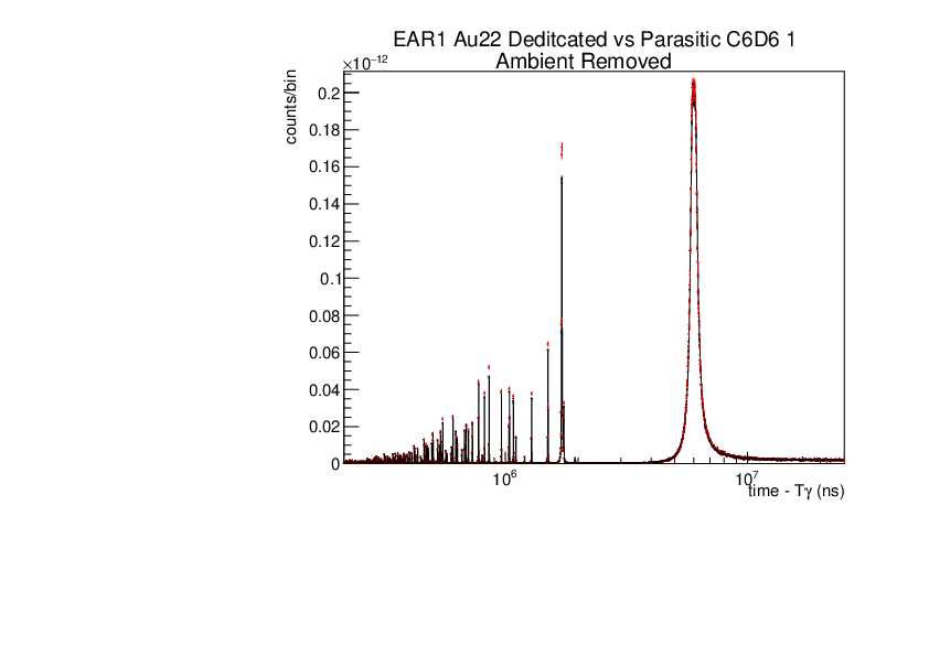
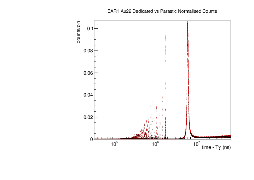
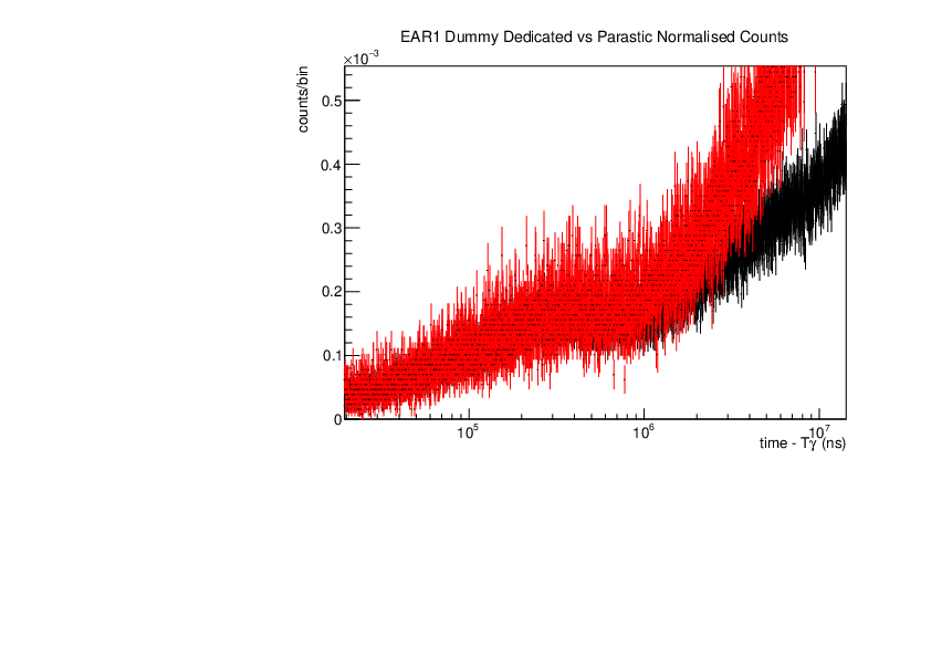
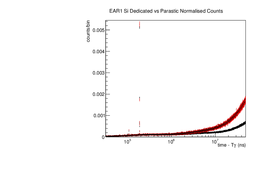
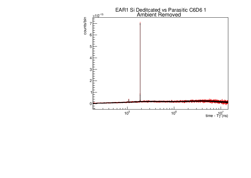
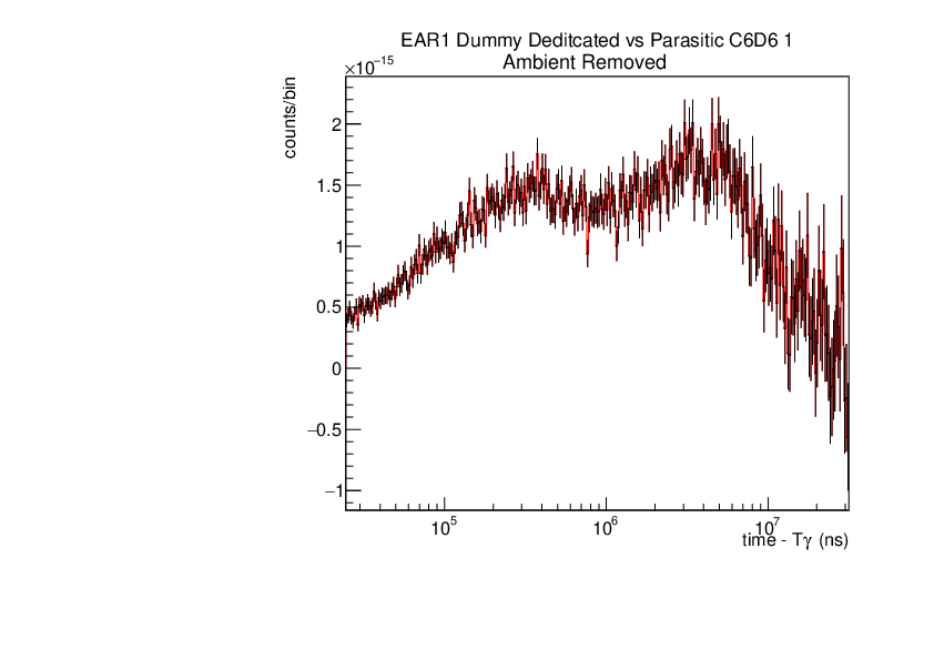
Michael Donnachie | EAR1 Parasitic vs Dedicated runs | Below are the histograms of parasitic vs dedicated runs for EAR1. Also included are histograms with ambient background removed which closes the gap between parasitic and dedicated histograms. This was preformed by scaling the ambient by counts by a multiplication of (dedicated or parasitic) bunch number/ambient bunch number. There are no legends but the dedicated counts are in black and parasitic counts in red. Only included are C6D6 1 detectors but the other three detectors were equivelant.
|
| Attachment 1: Au22_large_range_ambrem_A.pdf
|
|
| Attachment 2: Au22_large_range.pdf
|
|
| Attachment 3: Dummy_large_range.pdf
|
|
| Attachment 4: Si_large_range.pdf
|
|
| Attachment 5: Si_Resonance_ambrem_B.pdf
|
|
| Attachment 6: Dummy_large_range_ambrem.pdf
|
|
|
45
|
Mon Aug 28 14:07:23 2023 |
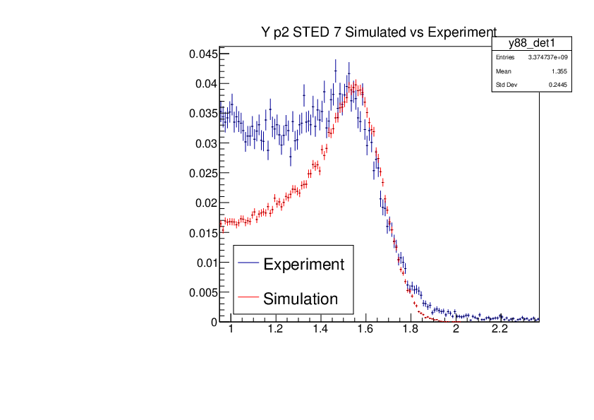
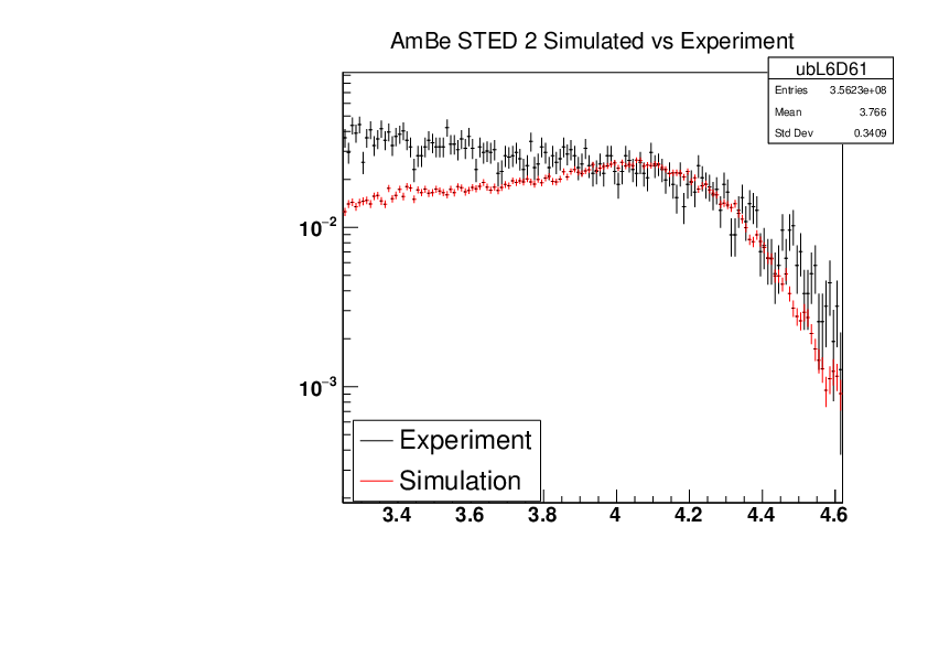
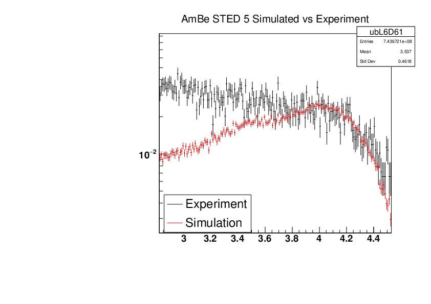
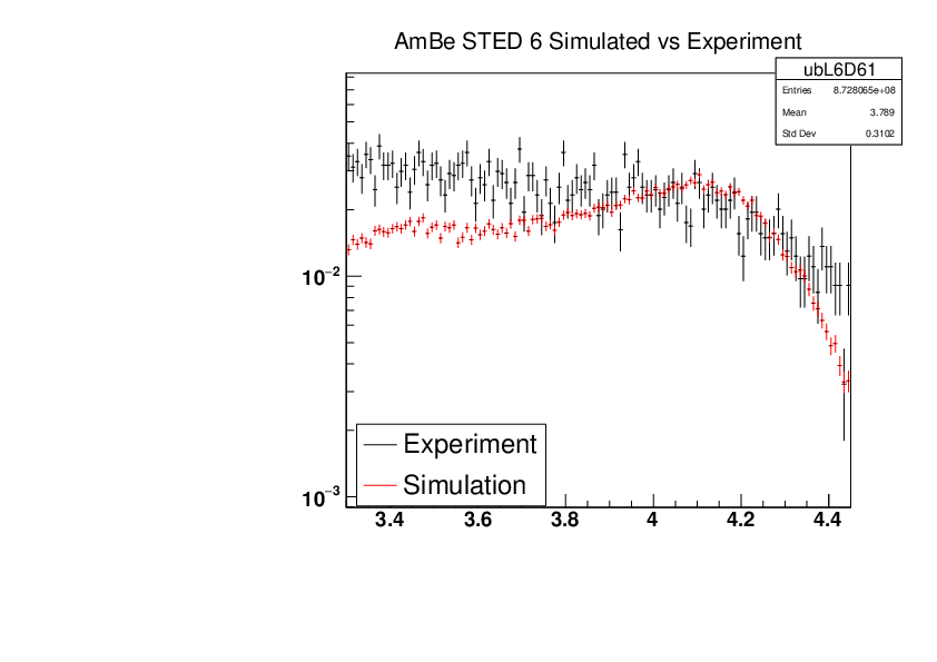
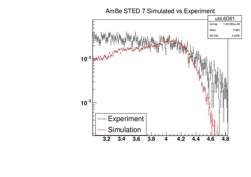
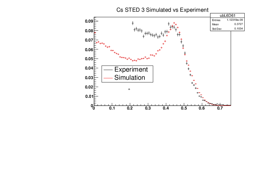
Michael Donnachie | EAR2 Experiment vs Simulated Amplitude Spectrums | Attatched are the overlayed compton edges for the calibrated experimental and the GEANT4 simulations. Note p1 and p2 denotes the lower and higher energy compton edges for Yttrium.
The experimental and simulated histograms are shifted in quite a few of these plots suggesting the calibration was not fully successful. The compton edge for AmBe was difficult to locate and may have contributed to the poor calibration. |
| Attachment 1: YP2_STED5_Experiment_vs_Simulated.pdf
|

|
| Attachment 2: YP2_STED6_Experiment_vs_Simulated.pdf
|

|
| Attachment 3: YP2_STED7_Experiment_vs_Simulated.pdf
|
|
| Attachment 4: AmBe_STED1_Experiment_vs_Simulated.pdf
|

|
| Attachment 5: AmBe_STED2_Experiment_vs_Simulated.pdf
|
|
| Attachment 6: AmBe_STED3_Experiment_vs_Simulated.pdf
|

|
| Attachment 7: AmBe_STED4_Experiment_vs_Simulated.pdf
|

|
| Attachment 8: AmBe_STED5_Experiment_vs_Simulated.pdf
|
|
| Attachment 9: AmBe_STED6_Experiment_vs_Simulated.pdf
|
|
| Attachment 10: AmBe_STED7_Experiment_vs_Simulated.pdf
|
|
| Attachment 11: Cs_STED1_Experiment_vs_Simulated.pdf
|

|
| Attachment 12: Cs_STED2_Experiment_vs_Simulated.pdf
|

|
| Attachment 13: Cs_STED3_Experiment_vs_Simulated.pdf
|
|
| Attachment 14: Cs_STED4_Experiment_vs_Simulated.pdf
|

|
| Attachment 15: Cs_STED5_Experiment_vs_Simulated.pdf
|

|
| Attachment 16: Cs_STED6_Experiment_vs_Simulated.pdf
|

|
| Attachment 17: Cs_STED7_Experiment_vs_Simulated.pdf
|

|
| Attachment 18: YP1_STED1_Experiment_vs_Simulated.pdf
|

|
| Attachment 19: YP1_STED2_Experiment_vs_Simulated.pdf
|

|
| Attachment 20: YP1_STED3_Experiment_vs_Simulated.pdf
|

|
| Attachment 21: YP1_STED4_Experiment_vs_Simulated.pdf
|

|
| Attachment 22: YP1_STED5_Experiment_vs_Simulated.pdf
|

|
| Attachment 23: YP1_STED6_Experiment_vs_Simulated.pdf
|

|
| Attachment 24: YP1_STED7_Experiment_vs_Simulated.pdf
|

|
| Attachment 25: YP2_STED1_Experiment_vs_Simulated.pdf
|

|
| Attachment 26: YP2_STED2_Experiment_vs_Simulated.pdf
|

|
| Attachment 27: YP2_STED3_Experiment_vs_Simulated.pdf
|

|
| Attachment 28: YP2_STED4_Experiment_vs_Simulated.pdf
|

|
|
44
|
Mon Aug 28 12:21:09 2023 |
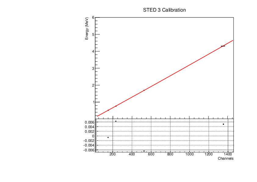
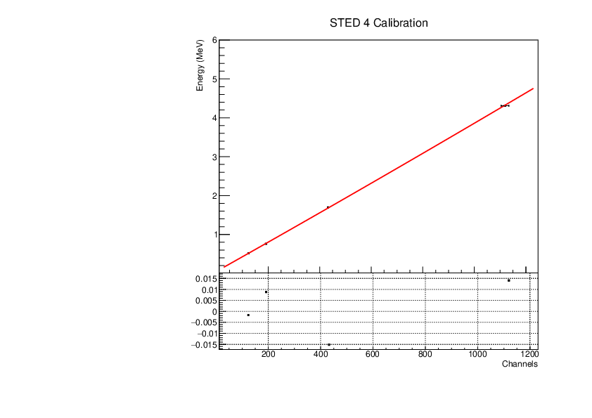
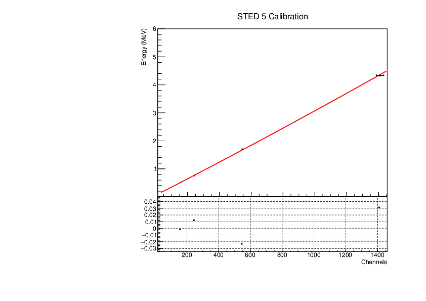
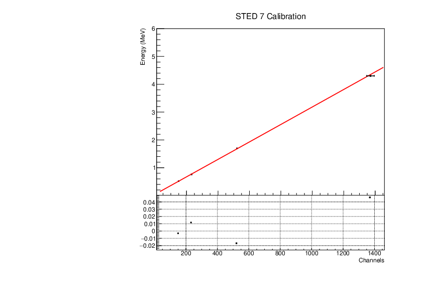
Michael Donnachie | EAR2 STED Calibration Parameters | Calibration parameters for each STED detector: With function f=p0+p1*x+p2*x*x
|
Detector
|
p0 Value |
p0 Error |
p1 Value |
p1 Error |
p2 Value |
p2 Error |
|
STED 1
|
5.67257E-02 |
|
|
|
|
6.80573E-08 |
| STED 2 |
|
|
|
|
|
7.35018E-08 |
| STED 3 |
|
|
|
|
|
5.55624E-08 |
| STED 4 |
|
|
|
|
|
7.71976E-08 |
| STED 5 |
|
|
|
|
|
5.75051E-08 |
| STED 6 |
|
|
|
|
|
5.06241E-08 |
| STED 7 |
|
|
|
|
|
5.79147E-08 |
A quadratic function was fitted to the reference point channel (from experimental histogram) and reference point energy (from simulation histogram). The reference point 'r' was r=mean+(FWHM/2) for a gaussian fitted to each compton edge. A quadratic function was used as it fitted the higher energy AmBe reference point better than a linear function. This is highlighted by the comparisson of "STED 2 Calibration" and "STED 2 Example Linear Fit Calibration" plots below. The p0 error is quite large and p2 error very large (larger than the parameter value in STED1) - however the parameters are highly correlated which may have inflated the error.
CmC histograms were not used as the compton edge could not be located.
For reference the STED 1 correlation matrix:
| |
p0 |
p1 |
p2 |
| p0 |
1 |
-0.92473 |
0.78779 |
| p1 |
-0.92473 |
1 |
-0.91714 |
| p2 |
0.78779 |
-0.91714 |
1 |
|
| Attachment 1: Example_STED2_calibration.pdf
|

|
| Attachment 2: STED1_calibration.pdf
|

|
| Attachment 3: STED2_calibration.pdf
|

|
| Attachment 4: STED3_calibration.pdf
|
|
| Attachment 5: STED4_calibration.pdf
|
|
| Attachment 6: STED5_calibration.pdf
|
|
| Attachment 7: STED6_calibration.pdf
|

|
| Attachment 8: STED7_calibration.pdf
|
|
|
43
|
Fri Aug 4 10:45:05 2023 |
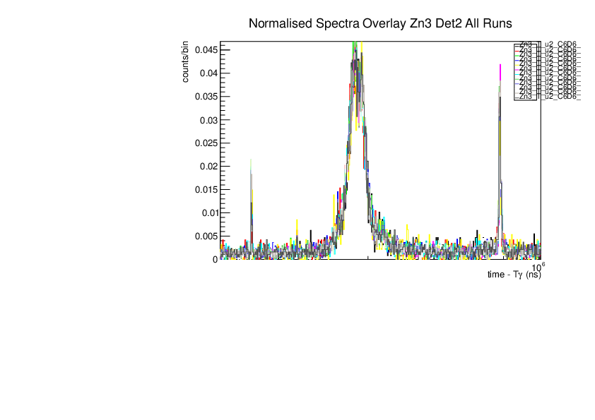
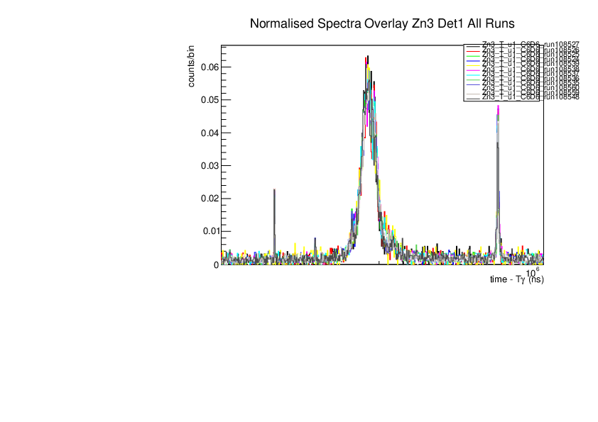
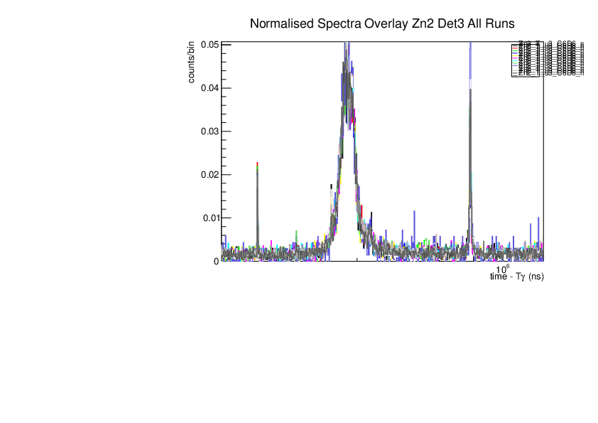
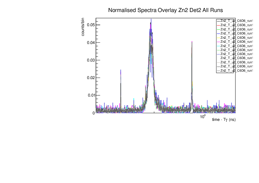
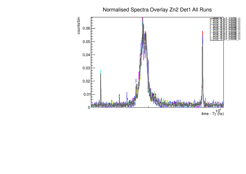
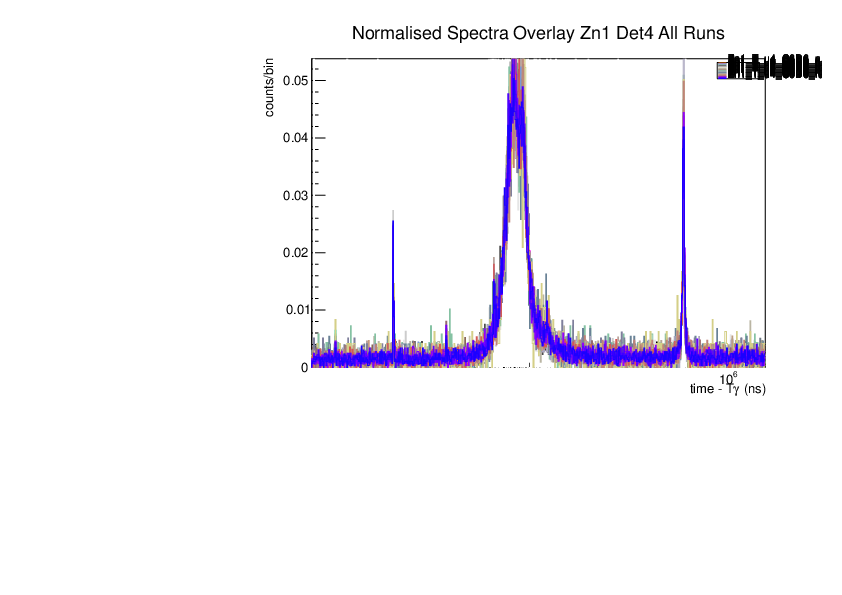
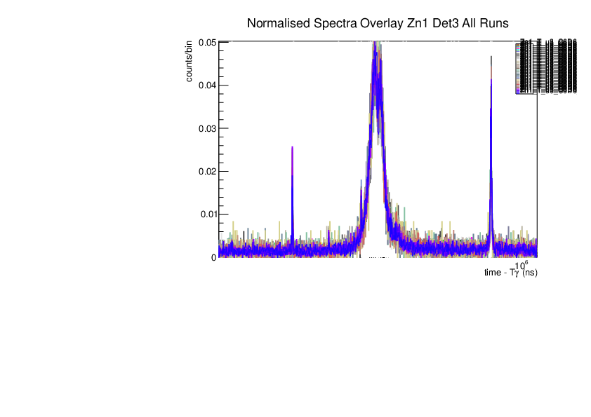
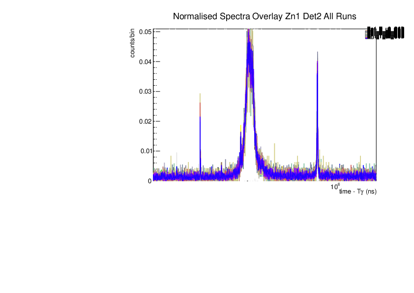
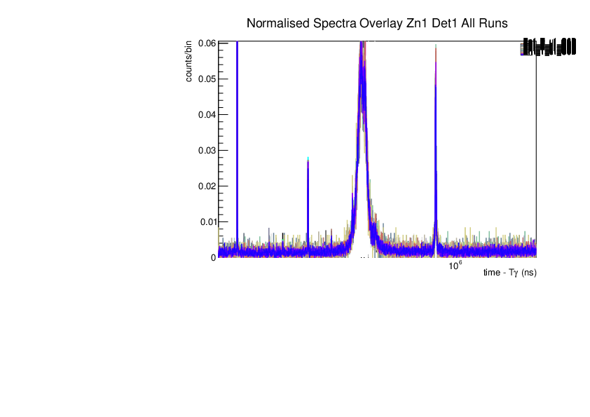
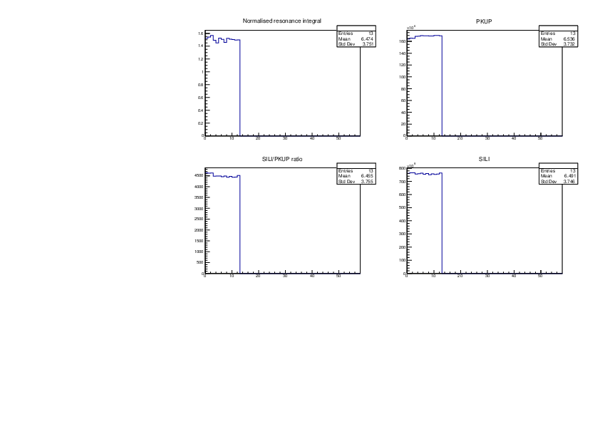
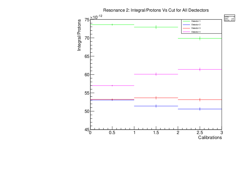
Annie | Zn Plots: Normalised Spectra, Ratio Plots, Integral/Protons vs Cut (all dets) | All plots in the ratios all look pretty contstant. Zn1 for all detectors seems to have some strange spike in the integral, and a dip in the SILI measurements (and therefore in the SILI/PKUP ratio).
Det1 & Det4 dont look great for the Integral/Proton plots, im planning to make these plots with the PKUP protons and SILI and then comapre all of those errors and ratios that come from those, so we'll see what that comparison brings.
Nothing has been seperated by dedicated or paracitic beam yet, so those comparisons need to be made too. |
| Attachment 1: Norm_spec_zn3_det4_singles.pdf
|

|
| Attachment 2: Norm_spec_zn3_Det3_singles.pdf
|

|
| Attachment 3: Norm_spec_zn3_det2_singles.pdf
|
|
| Attachment 4: Norm_spec_zn3_det1_singles.pdf
|
|
| Attachment 5: Norm_spec_zn2_det4_singles.pdf
|

|
| Attachment 6: Norm_spec_zn2_det3_singles.pdf
|
|
| Attachment 7: Norm_spec_zn2_det2_singles.pdf
|
|
| Attachment 8: Norm_spec_zn2_det1_singles.pdf
|
|
| Attachment 9: Norm_spec_zn1_det4_singles.pdf
|
|
| Attachment 10: Norm_spec_zn1_det3_singles.pdf
|
|
| Attachment 11: Norm_spec_zn1_det2_singles.pdf
|
|
| Attachment 12: Norm_spec_zn1_det1_singles.pdf
|
|
| Attachment 13: Ratio_plot_zn3_det4.pdf
|

|
| Attachment 14: Ratio_plot_zn3_det3.pdf
|

|
| Attachment 15: Ratio_plot_zn3_det2.pdf
|

|
| Attachment 16: Ratio_plot_zn3_det1.pdf
|

|
| Attachment 17: Ratio_plot_zn2_det4.pdf
|

|
| Attachment 18: Ratio_plot_zn2_det3.pdf
|

|
| Attachment 19: Ratio_plot_zn2_det2.pdf
|

|
| Attachment 20: Ratio_plot_zn2_det1.pdf
|
|
| Attachment 21: Ratio_plot_zn1_det4.pdf
|

|
| Attachment 22: Ratio_plot_zn1_det3.pdf
|

|
| Attachment 23: Ratio_plot_zn1_det2.pdf
|

|
| Attachment 24: Ratio_plot_zn1_det1.pdf
|

|
| Attachment 25: zn_res3_vs_protons.pdf
|

|
| Attachment 26: zn_res2_vs_protons.pdf
|
|
| Attachment 27: zn_res3_vs_protons.pdf
|

|
|
42
|
Mon Jul 31 12:00:02 2023 |
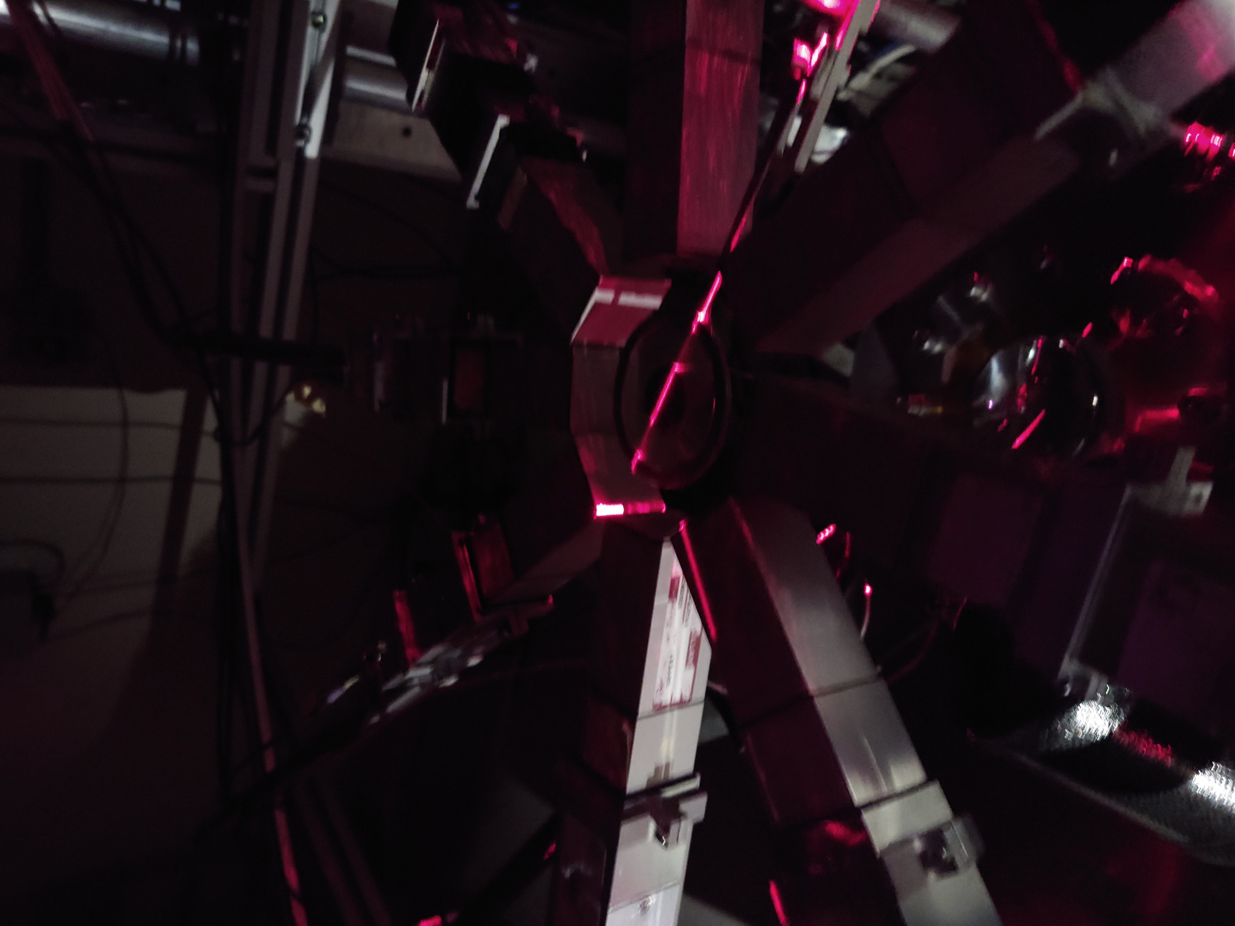
Nikolay Sosnin | EAR2 Silicon Samples | |
| Attachment 1: EAR2_30Si.JPG
|

|
| Attachment 2: EAR2_Sinat_Closeup.JPG
|

|
| Attachment 3: Goodfellow_Sinat_Sample.JPG
|

|
| Attachment 4: Laser_Alignment.JPG
|
|
|
41
|
Fri Jul 28 12:19:10 2023 |
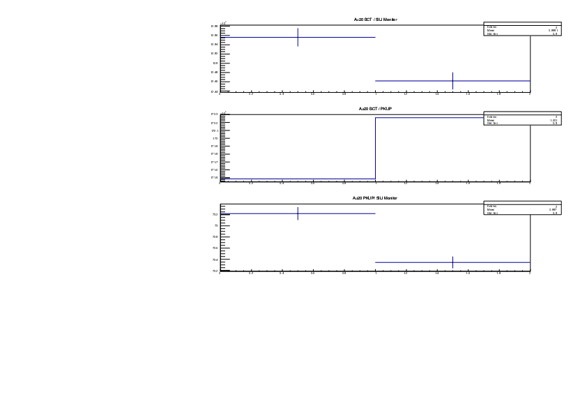
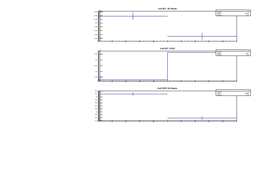
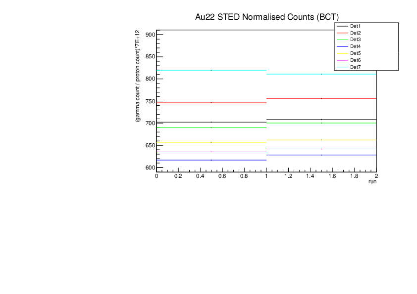
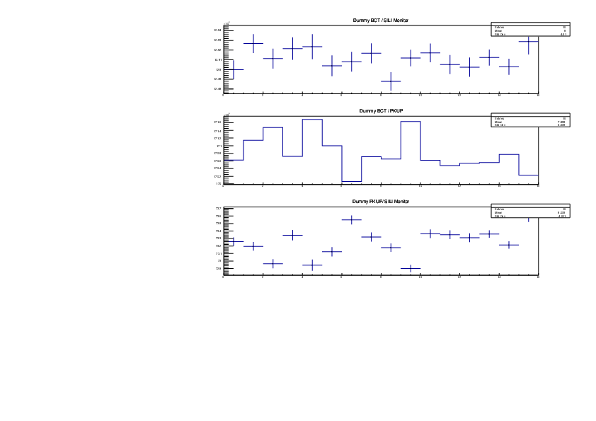
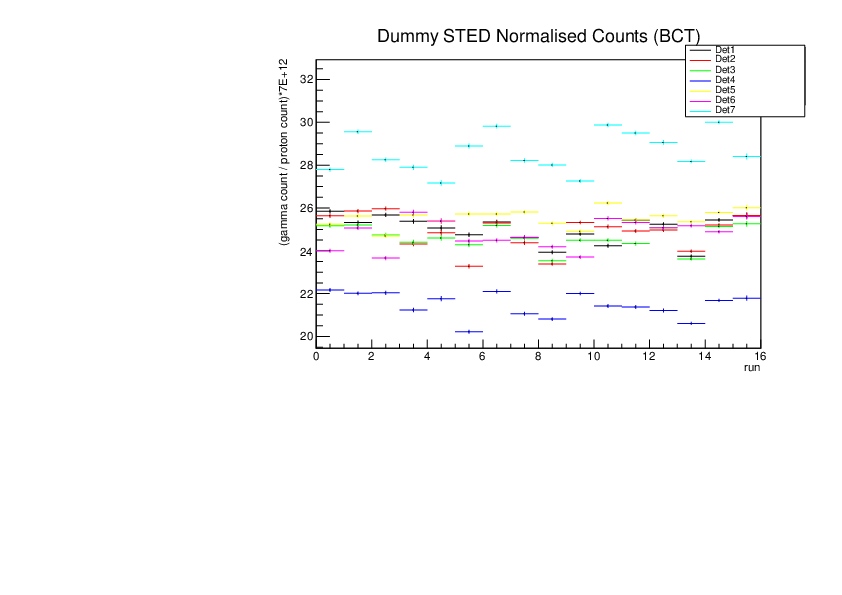
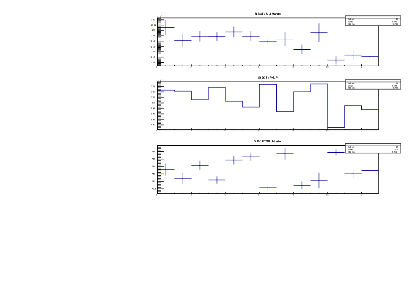
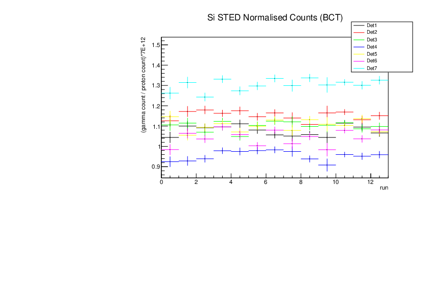
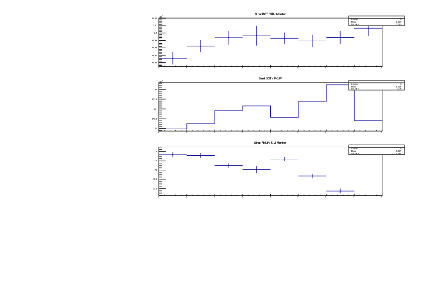
Michael Donnachie | EAR2 consistency checks, PKUP BCT SILI and normalised counts | The EAR2 ratios of BCT/PKUP, BCT/SILI and PKUP/SILI plotted for each run for samples Si, Sinat, Au20, Au22 and Dummy.
Also included is the normalised counts (counts/BCT) with 7 detectors on one plot (STED8 was ommited). 'counts' for Si was integreated over the Si resonance, for Au it was integrated over the largest resonance. For Dummy and Sinat the counts were integrated over a large range of 1e+4 to 1e+6ns. The Sinat resonance was too small for adequate statistics to only integrate over the resonance hence why a large range was used. The C6D6 normalised counts were not plotted as there seems to be issues with this detector in EAR2.
|
| Attachment 1: Au20_Ratios.pdf
|
|
| Attachment 2: Au20_STED_normalised_counts.pdf
|

|
| Attachment 3: Au22_Ratios.pdf
|
|
| Attachment 4: Au22_STED_normalised_counts.pdf
|
|
| Attachment 5: Dummy_Ratios.pdf
|
|
| Attachment 6: Dummy_STED_normalised_counts.pdf
|
|
| Attachment 7: Si_Ratios.pdf
|
|
| Attachment 8: Si_STED_normalised_counts.pdf
|
|
| Attachment 9: Sinat_Ratios.pdf
|
|
| Attachment 10: Sinat_STED_normalised_counts.pdf
|

|
|
40
|
Fri Jul 28 12:07:33 2023 |
Michael Donnachie | EAR2 C6D6 timeshift issues | There seems to be issues with the EAR2 C6D6 T histograms. For Au the earlier run seems to be shifted for detector 2 compared to the rest.
For Si plotted is 3 different runs 216123, 216128 and 216135 for both detectors. The histogram is messy but highlights that there is a problem. The single Si resonace should be around 20 000ns and this is only the case for run216128.
Apologies for no legend on plots.
Au22
det1 run216158 black
det1 run216109 red
det2 run216158 green
det2 run216109 blue
Au22
det1 run216157 black
det1 run216108 red
det2 run216157 green
det2 run216108 blue
|
| Attachment 1: Au20_C6D6_both_det_timeshift.pdf
|

|
| Attachment 2: Au22_C6D6_both_det_timeshift.pdf
|

|
| Attachment 3: Si30_C6D6_bothdet_3runs.pdf
|

|
|
39
|
Mon Jul 24 10:32:39 2023 |
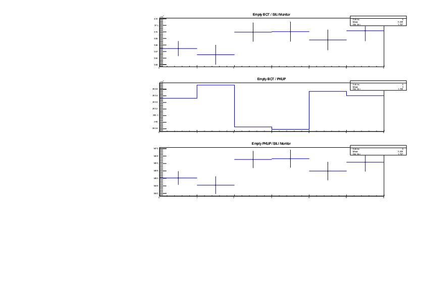
Michael Donnachie | Consistency Checks BCT PKUP SILI | The EAR1 ratios of BCT/PKUP, BCT/SILI and PKUP/SILI plotted for each run for samples Si, Sinat goodfellow, Au20, Au22, Empty and Dummy. |
| Attachment 1: Si_Ratios.pdf
|

|
| Attachment 2: Au22_Ratios.pdf
|

|
| Attachment 3: Au20_Ratios.pdf
|

|
| Attachment 4: Dummy_Ratios.pdf
|

|
| Attachment 5: Sinat_Goodfellow_Ratios.pdf
|

|
| Attachment 6: Empty_Ratios.pdf
|
|
|
38
|
Fri Jul 21 10:45:22 2023 |
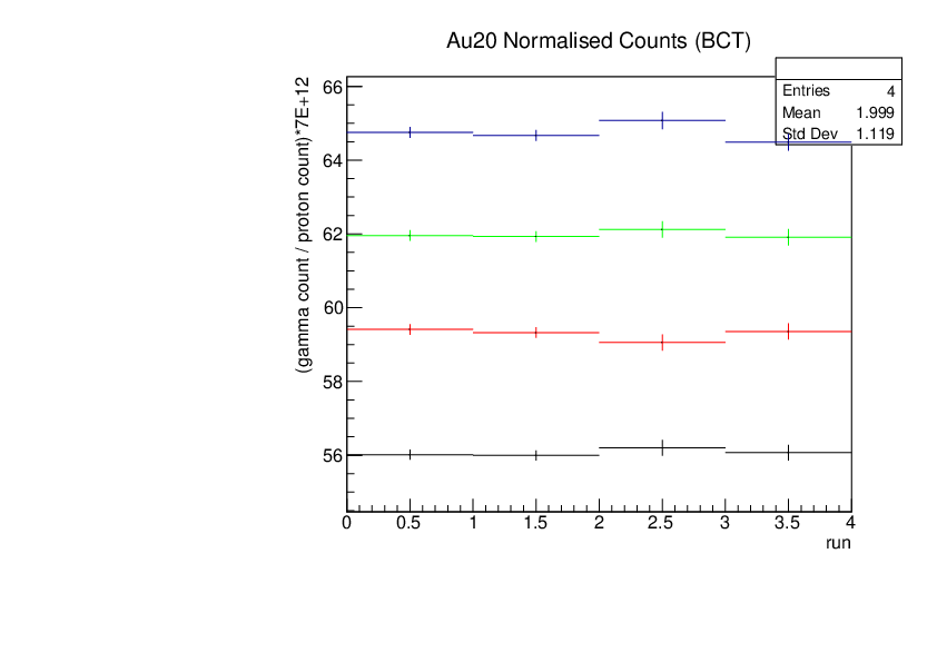
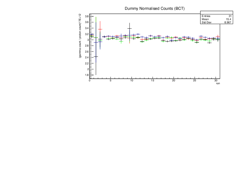
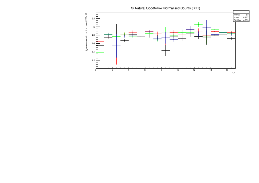
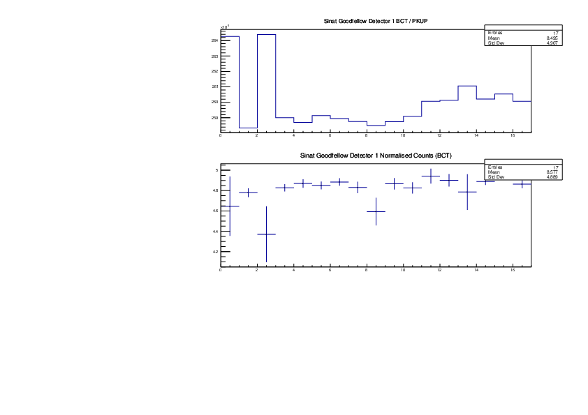
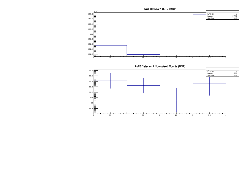
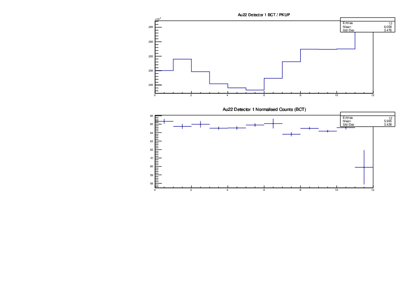
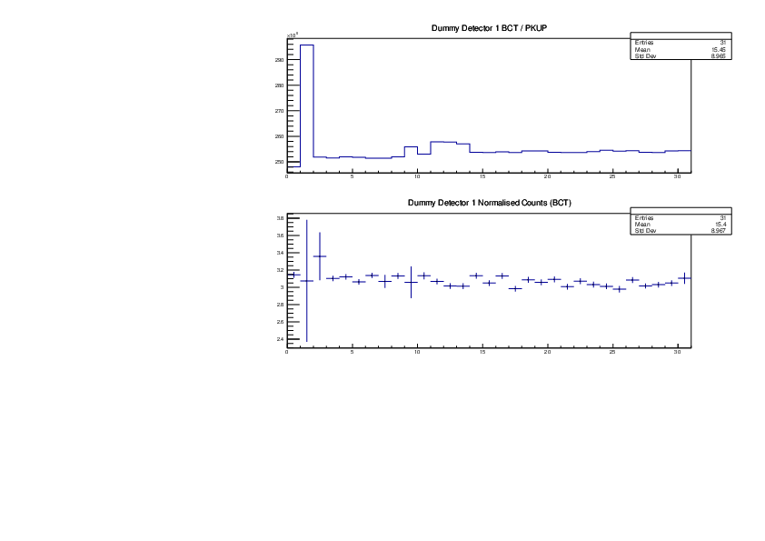
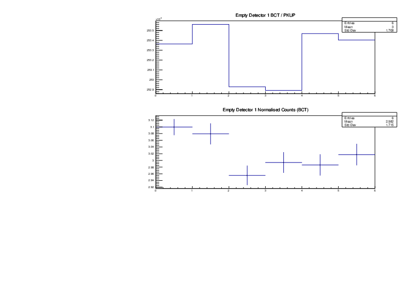
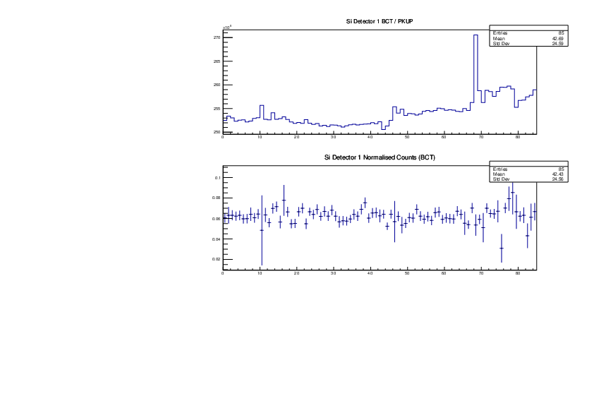
Michael Donnachie | Consistency Checks BCT PKUP comparrisons | The ratios for BCT/PKUP for Si, Au20, Au22, Dummy, Empty and Sinat goodfellow have been plotted. Also included is the normalised counts (counts/BCT) with all 4 detectors on one plot. Apologies there is not a legend, however det1 is red, det2 is green, det3 black and det4 blue. 'counts' for Si was integreated over the Si resonance, for Au it was integrated over the largest resonance. For Dummy, Empty and Sinat the counts were integrated over a large range of 1e+5 to 1e+7ns. The Sinat resonance was too small for adequate statistics to only integrate over the resonance hence why a large range was used.
|
| Attachment 1: Au20NormalisedCounts.pdf
|
|
| Attachment 2: Au22NormalisedCounts.pdf
|

|
| Attachment 3: DummyNormalisedCounts.pdf
|
|
| Attachment 4: EmptyNormalisedCounts.pdf
|

|
| Attachment 5: SinatgoodNormalisedCounts.pdf
|
|
| Attachment 6: SiNormalisedCounts.pdf
|

|
| Attachment 7: Sinat_Goodfellow_det1_Detector_Ratios.pdf
|
|
| Attachment 8: Au20_det1_Detector_Ratios.pdf
|
|
| Attachment 9: Au22_det1_Detector_Ratios.pdf
|
|
| Attachment 10: Dummy_det1_Detector_Ratios.pdf
|
|
| Attachment 11: Empty_det1_Detector_Ratios.pdf
|
|
| Attachment 12: Si_det1_Detector_Ratios.pdf
|
|
|
37
|
Mon Jul 17 14:49:16 2023 |
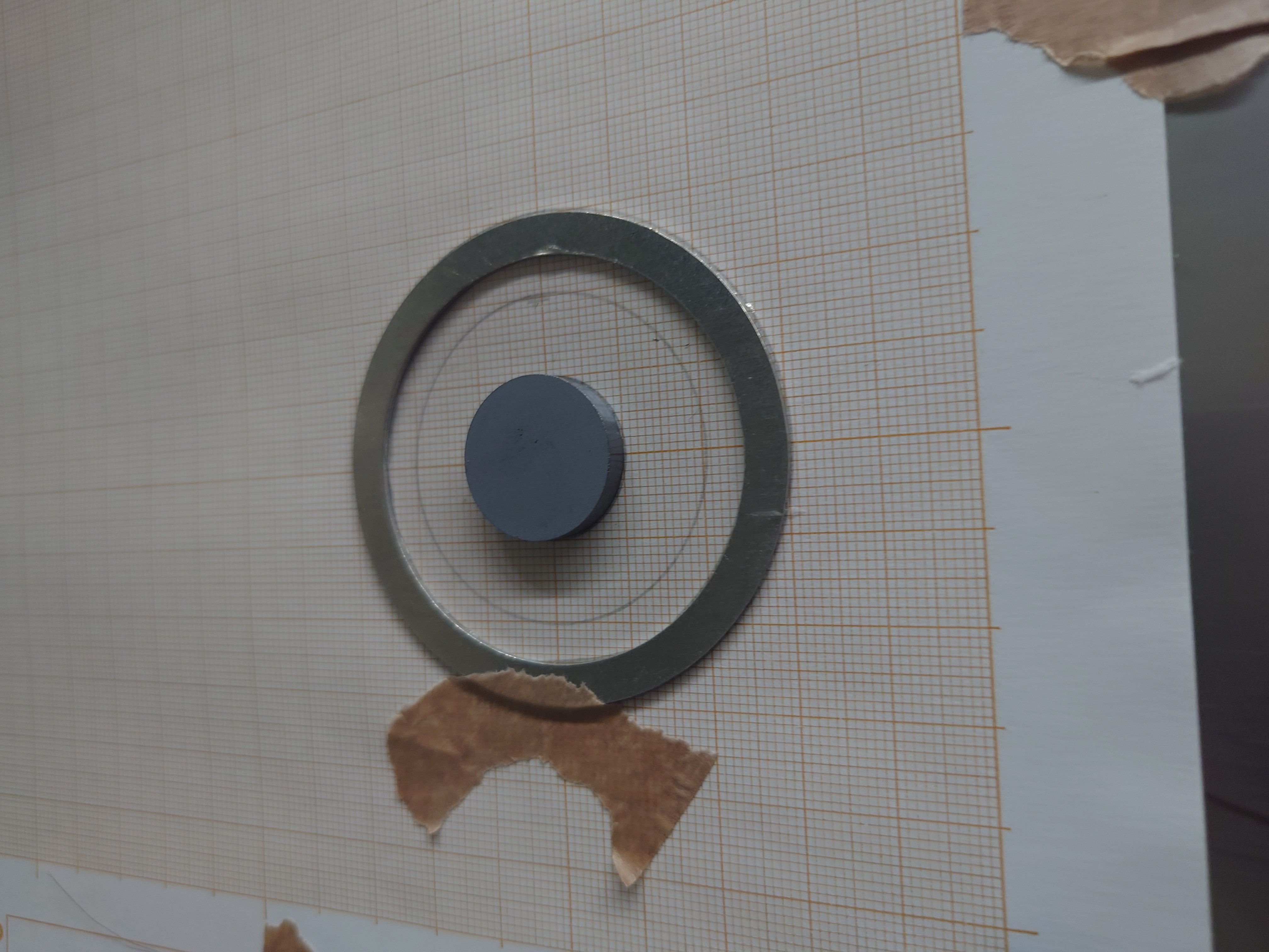
Nikolay Sosnin | Mounted Si-nat Sample | Goodfellow Si-nat mounted at EAR1. First run: 116551 |
| Attachment 1: Sinat_Back.JPG
|

|
| Attachment 2: Sinat_Front.JPG
|

|
| Attachment 3: Sinat_Sample.JPG
|
|
|
36
|
Mon Jul 17 12:30:28 2023 |
Nikolay Sosnin | Si-nat Goodfellow Sample Properties | Goodfellow sample has been deposited on a single Mylar foil and glue is drying.
mass = 2.932 g
diameter = 20.0 mm
thickness = 3.98 mm |
| Attachment 1: Sinat_Sample_Properties.JPG
|

|
|
35
|
Mon Jul 17 11:30:54 2023 |
Claudia | Properties Silicon powder samples | 30Si
Mass: 0.9925(1) g; Diameter: 22.22(1) mm; Thickness: 1.77(4) mm;
natSi
Mass: 1.0653(2)g; Diameter: 19.94(2) mm; Thickness: 1.91(3) mm;
Mass of sample pre-treatment (sintering ...)
natSi 1.0238 g
30Si: 0.75034 g |
|
34
|
Mon Jul 17 10:06:35 2023 |
Nikolay Sosnin | State of the Union: Campaign Update 17.07.2023 | EAR1: Si-nat sample fell off the holder during maintenance (before run 116544), appears intact and undamaged. Placed it back in-beam for further EAR1 measurements and subsequent transfer to EAR2.
EAR2: Replaced DUMMY with 30Si. Photo during alignment and photo of sample in holder attached. |
| Attachment 1: Sinat_PostFall.JPG
|

|
| Attachment 2: EAR2_30Si_Alignment.JPG
|

|
| Attachment 3: EAR2_30Si.JPG
|

|
|
33
|
Sat Jul 15 07:33:32 2023 |
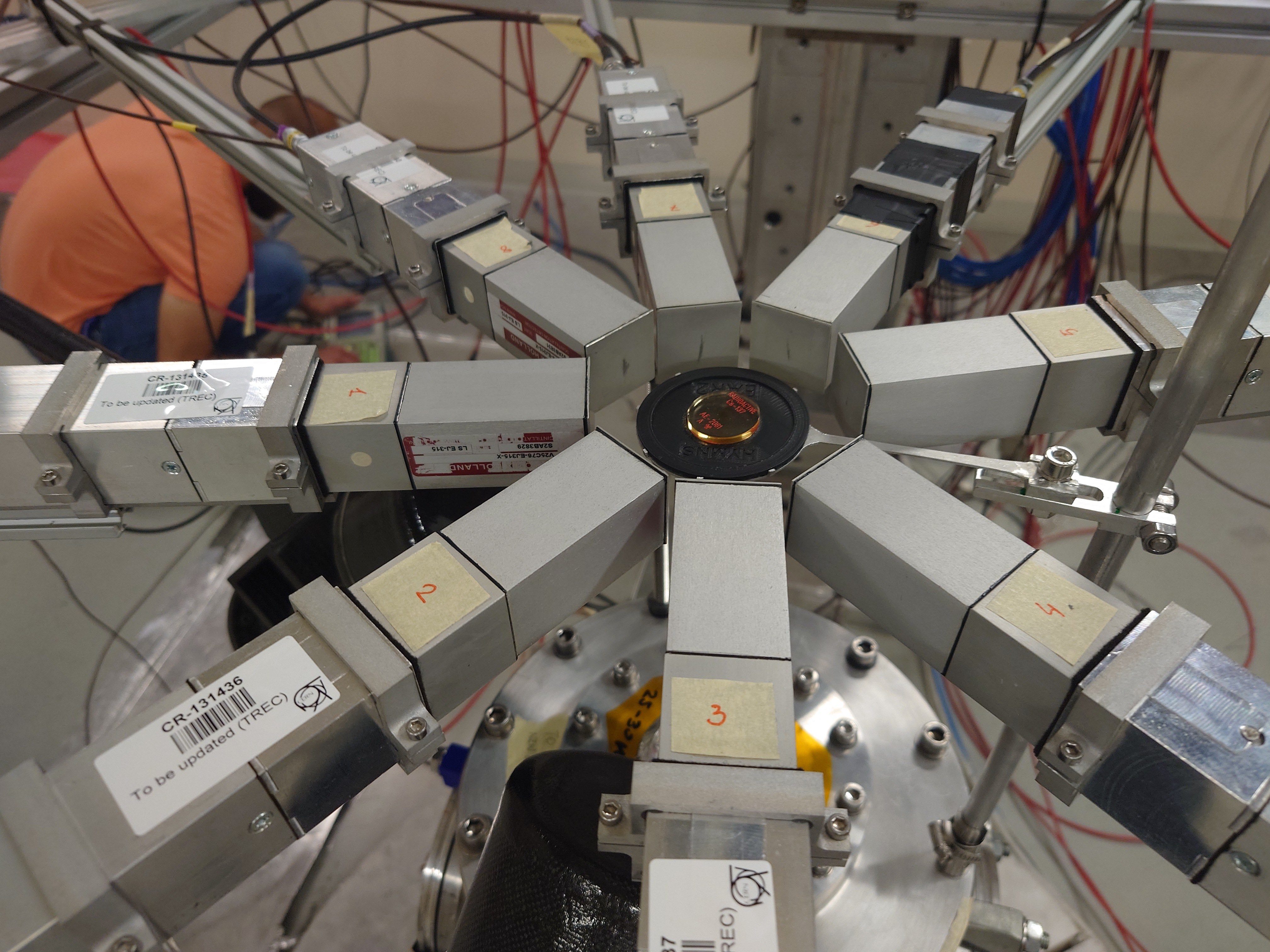
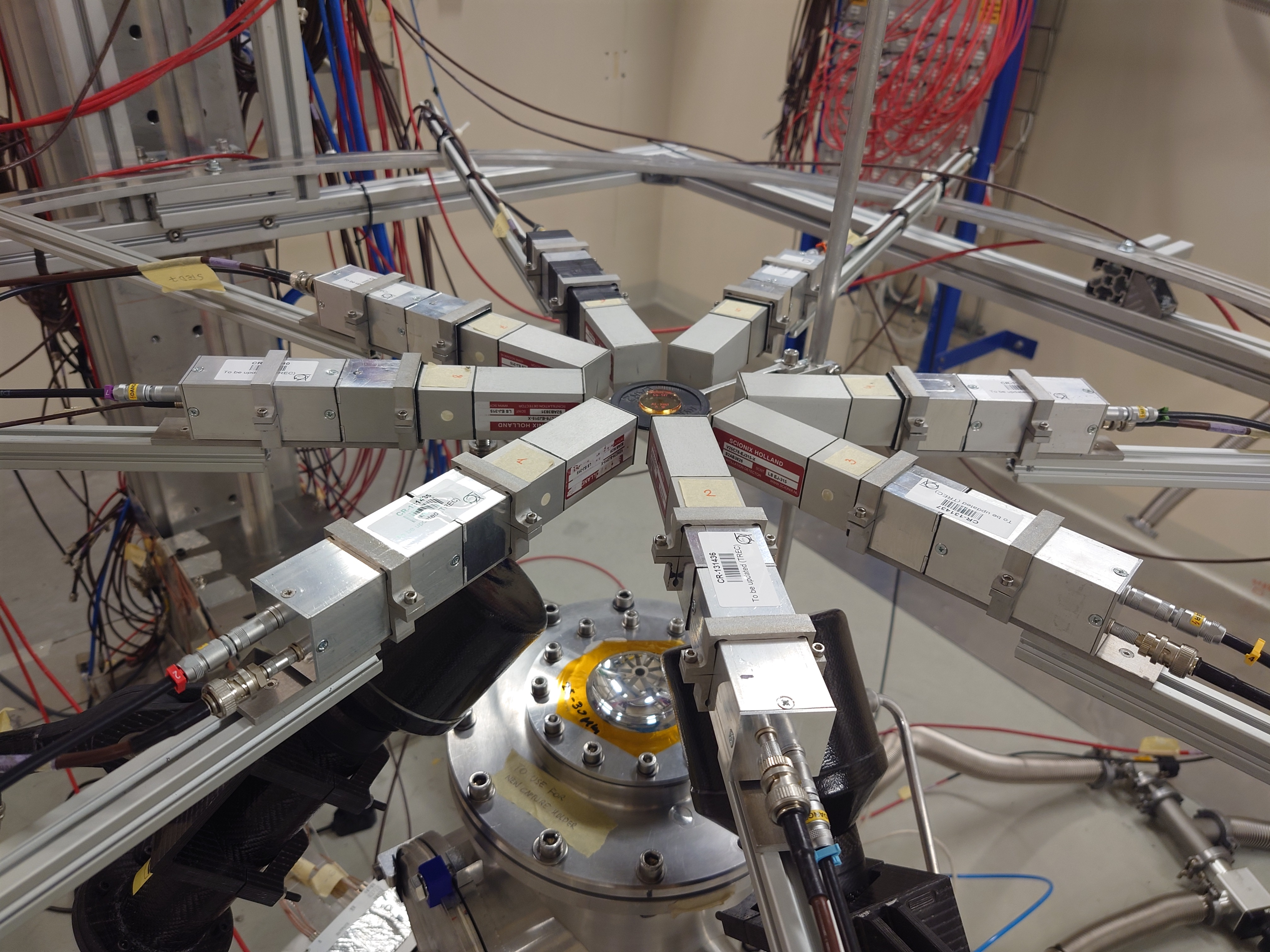
Nikolay Sosnin | 30Si EAR2 | 8 sTED + 2 C6D6
C6D6: distance = 14 cm, angle = 135 degrees
sTED horizontal ring, distance for each detector from target = 4.5 cm. sTED labeled 8 in the DAQ is actually sTED #9 at n_TOF (actual sTED #8 showed no signal)
sTED1 809V, sTED2 793V, sTED3 813V, sTED4 779V, sTED5 785V, sTED6 800V, sTED7 791V, sTED8 837V
C6D61 (labeled C6D6_M in HV log) 854V, C6D62 (labeled C6D6_N in HV log) 871V |
| Attachment 1: C6D6_sTED.JPG
|

|
| Attachment 2: sTED_Ring_Cs137.JPG
|
|
| Attachment 3: C6D6_sTED_Side.JPG
|

|
| Attachment 4: Beam_Kapton_Setup.JPG
|

|
| Attachment 5: EAR2_Setup2.JPG
|
|
| Attachment 6: EAR2_Setup.JPG
|

|
|
32
|
Thu Jul 13 14:19:37 2023 |
Claudia | dead time 30Si run | Default TTOFSort dead time setting of 30 ns is ok. |
| Attachment 1: consecutiveau22.pdf
|

|
|
31
|
Thu Jul 13 12:27:44 2023 |
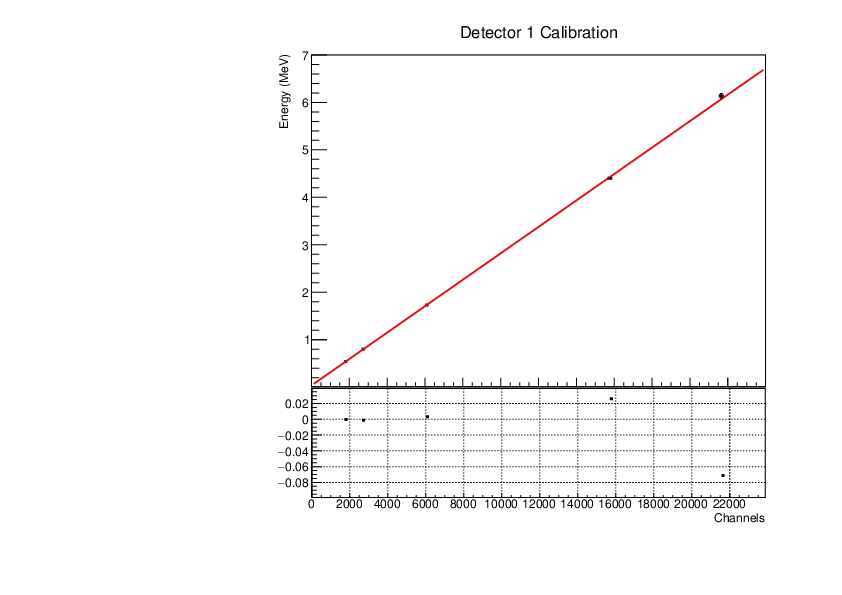
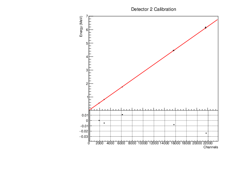
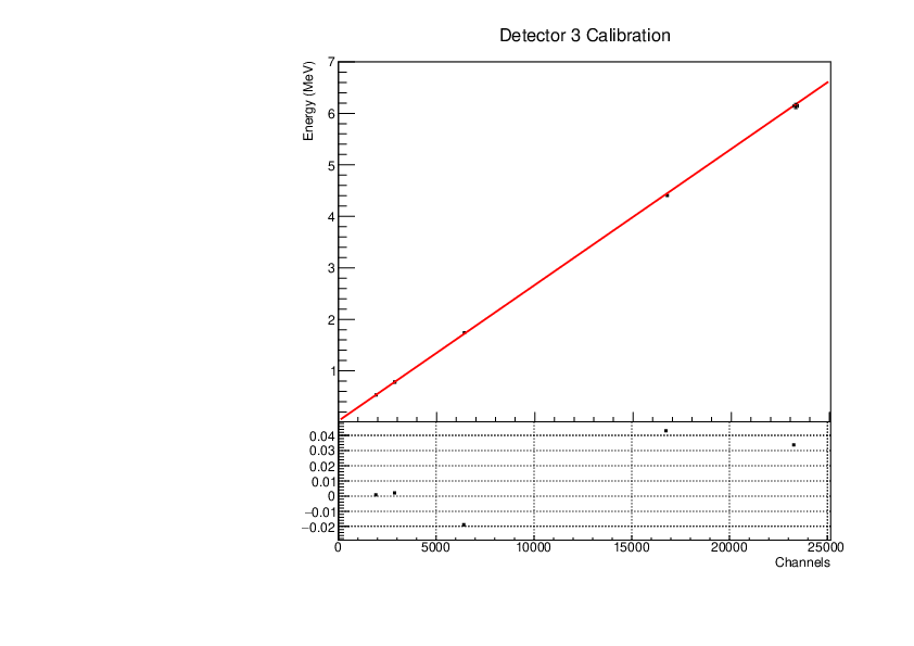
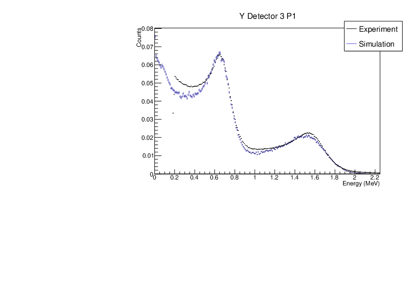
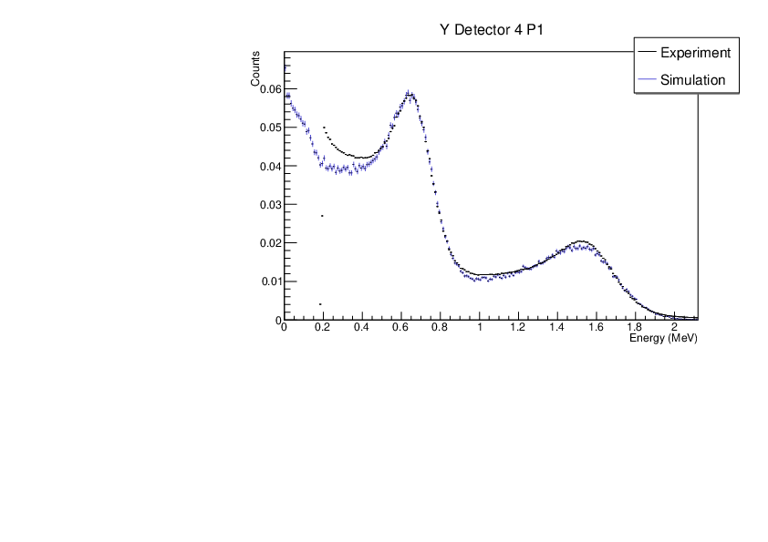
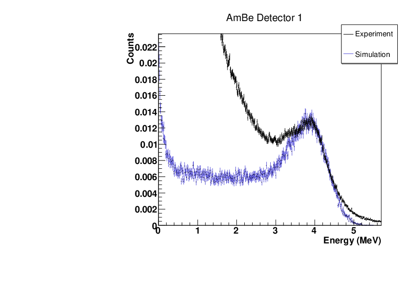
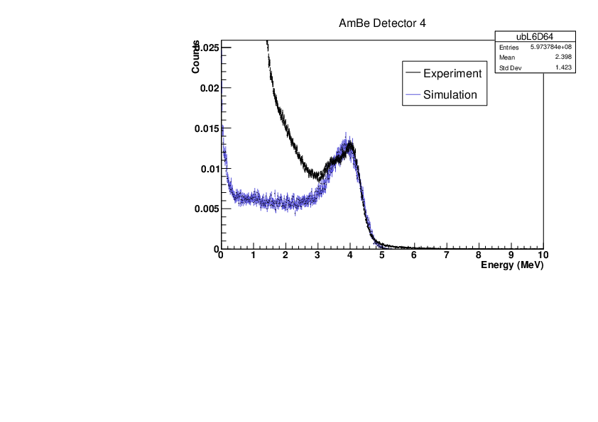
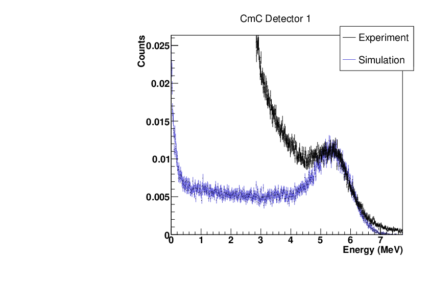
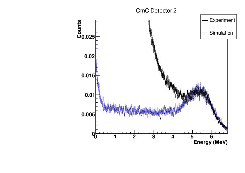
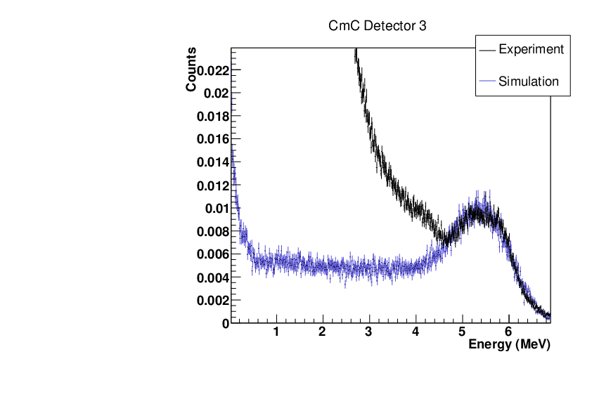
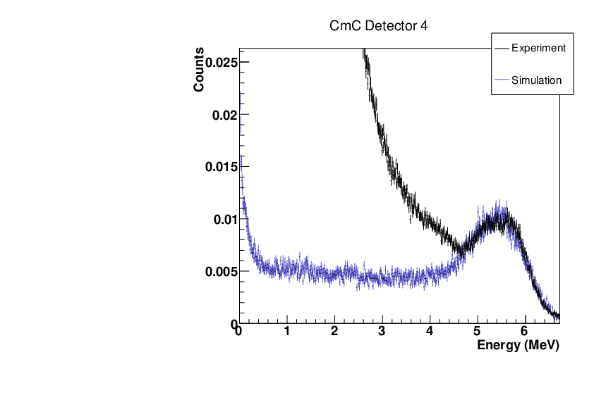
Michael Donnachie, CLW | Calibration Parameters | Calibration parameters for each detector:
| detector |
y-intercept (value) |
y-intercept (error) |
gradient (value) |
gradient (error) |
| 1 |
|
|
|
1.56343E-06 |
| 2 |
|
|
|
1.96751E-06 |
| 3 |
|
|
|
1.33883E-06 |
| 4 |
|
|
|
1.22941E-06 |
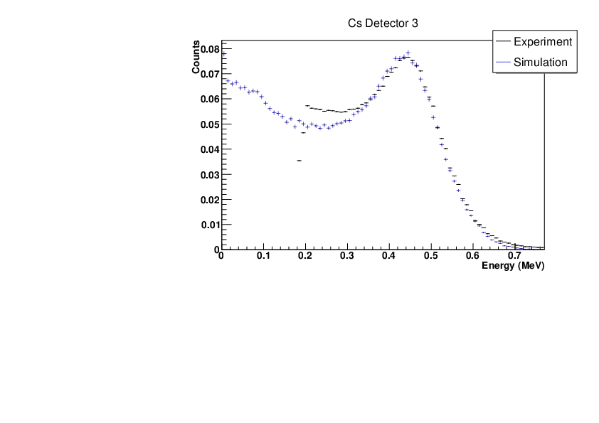
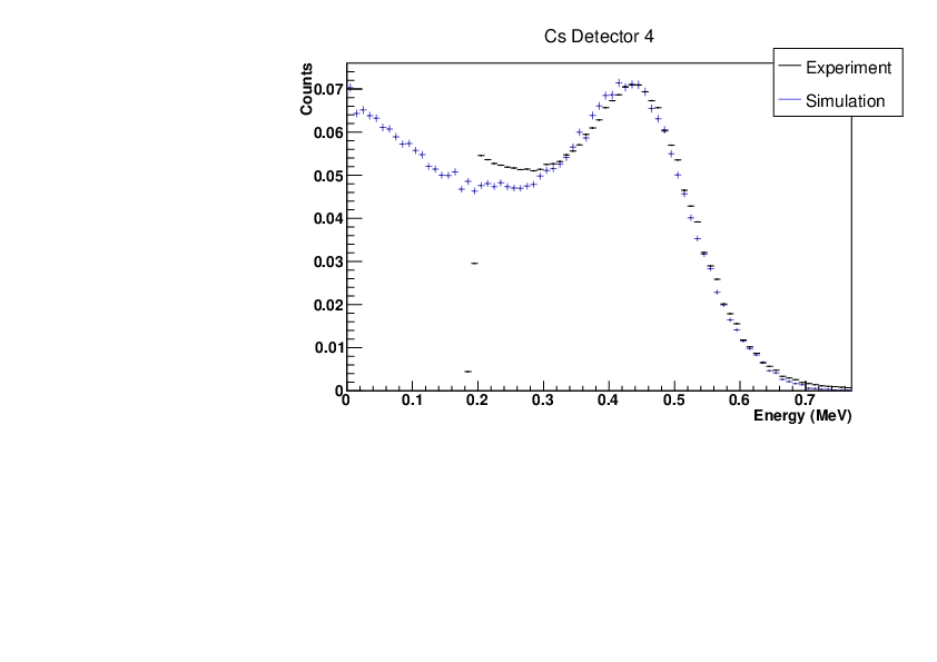
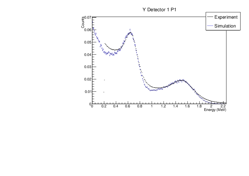
A linear function was fitted to the reference point channel (from experimental histogram) and reference point energy (from simulation histogram). The reference point 'r' was r=mean+(FWHM/2) for a gaussian fitted to each compton edge.
The comparrisons between the calibrated experimental and simulation histograms has been attached. P1 (left) and P2 (right) on the Y88 hisograms indicate whether the histograms were scaled with respect to the leftmost or rightmost compton edge (only to allow easier comparrison).
Broadening parameters applied to the simulations
float a1 = 0.004947965;
float b1 = 0.005227974;
float a2 = 0.007163802;
float b2 = 0.007549987;
float a3 = 0.001256462;
float b3 = 0.006410511;
float a4 = 0.003907402;
float b4 = 0.004033837;
sigma= sqrt(axE+bxE^2) |
| Attachment 1: det1.pdf
|
|
| Attachment 2: det2.pdf
|
|
| Attachment 3: det3.pdf
|
|
| Attachment 4: det4.pdf
|

|
| Attachment 5: Ydet2p1.pdf
|

|
| Attachment 6: Ydet2p2.pdf
|

|
| Attachment 7: Ydet3p1.pdf
|
|
| Attachment 8: Ydet3p2.pdf
|

|
| Attachment 9: Ydet4p1.pdf
|
|
| Attachment 10: Ydet4p2.pdf
|

|
| Attachment 11: AmBedet1.pdf
|
|
| Attachment 12: AmBedet2.pdf
|

|
| Attachment 13: AmBedet3.pdf
|

|
| Attachment 14: AmBedet4.pdf
|
|
| Attachment 15: CmCdet1.pdf
|
|
| Attachment 16: CmCdet2.pdf
|
|
| Attachment 17: CmCdet3.pdf
|
|
| Attachment 18: CmCdet4.pdf
|
|
| Attachment 19: Csdet1.pdf
|

|
| Attachment 20: Csdet2.pdf
|

|
| Attachment 21: Csdet3.pdf
|
|
| Attachment 22: Csdet4.pdf
|
|
| Attachment 23: Ydet1p1.pdf
|
|
| Attachment 24: Ydet1p2.pdf
|

|
|
30
|
Thu Jun 29 09:21:13 2023 |
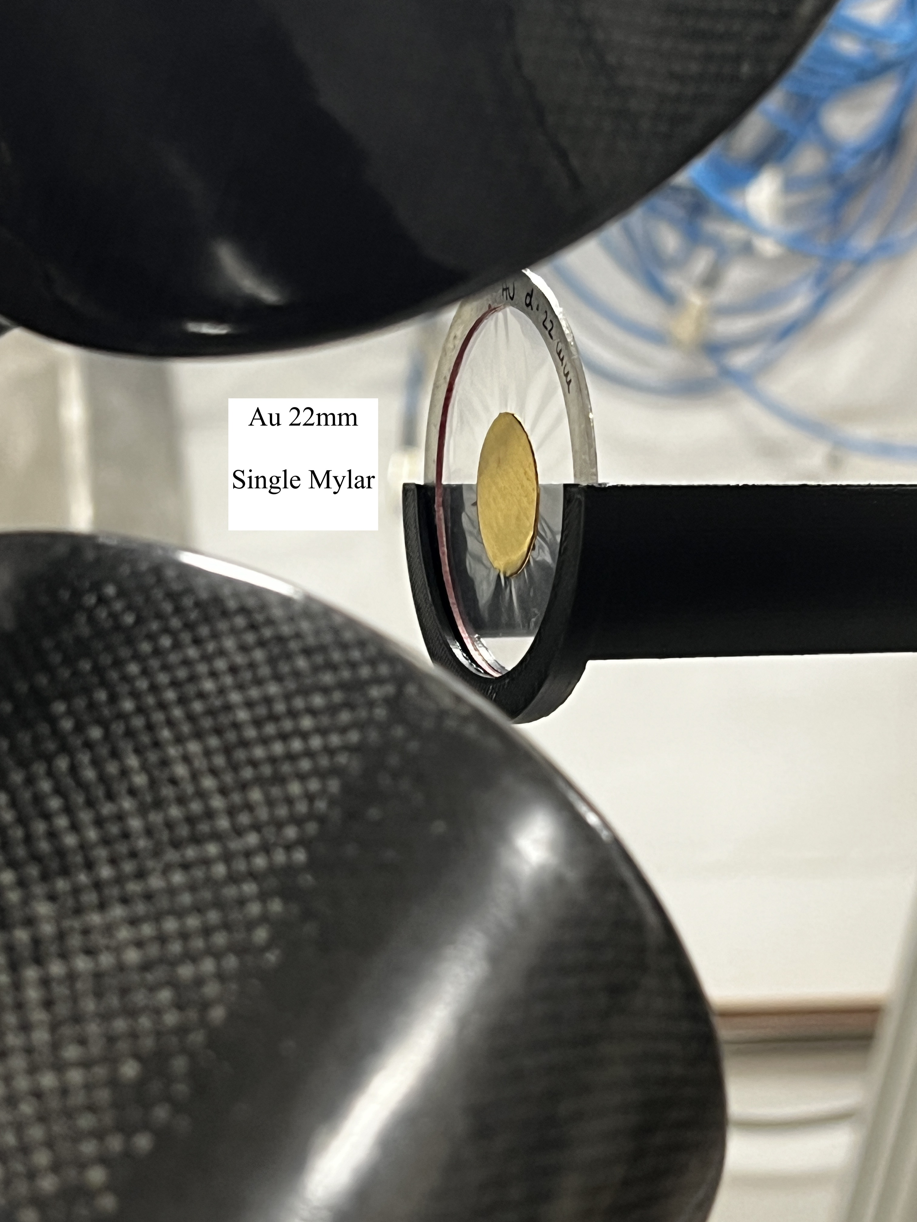
Annie | Info on Samples | Both Au samples (20mm and 22mm) are single mylar.
Both Si30 (22mm) and natSi (20mm) are double mylar.
Empty is single mylar ONLY
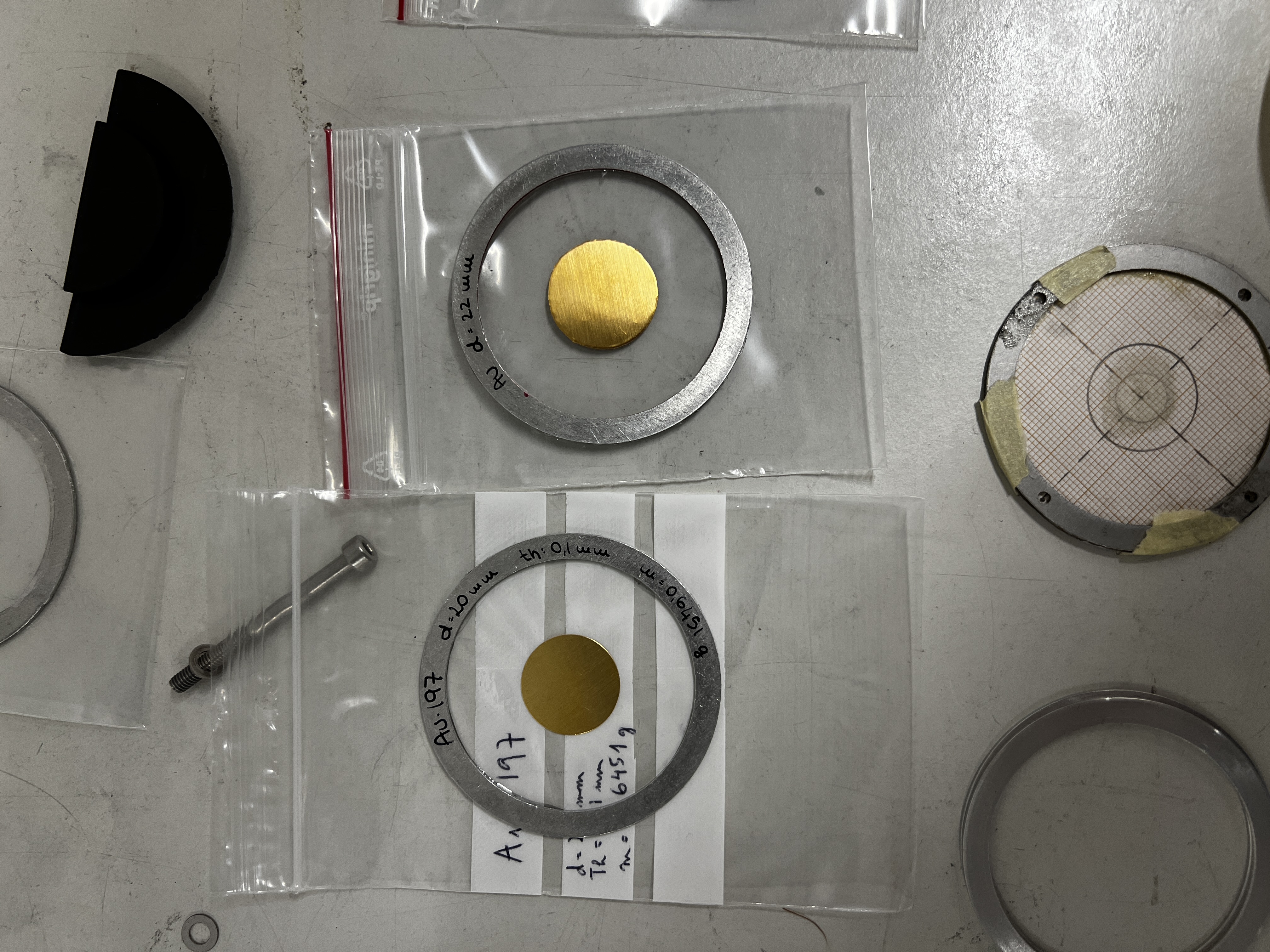
Dummy is double mylar + glue |
| Attachment 1: IMG_2242.JPG
|

|
| Attachment 2: IMG_2248.JPG
|

|
| Attachment 3: IMG_2247.JPG
|
|
| Attachment 4: IMG_2246.JPG
|

|
|
29
|
Thu Jun 22 10:37:39 2023 |
Annie | Gold 22mm Sample Images | New 22mm sample compared to old 20mm sample used at the beginning of the campaign + picture of dummy target in the setup. |
| Attachment 1: IMG_2187.JPG
|

|
| Attachment 2: IMG_2186.JPG
|
|
| Attachment 3: IMG_2185.JPG
|

|
|