| ID |
Date |
Author |
Subject |
|
5
|
Tue Oct 13 21:04:49 2015 |
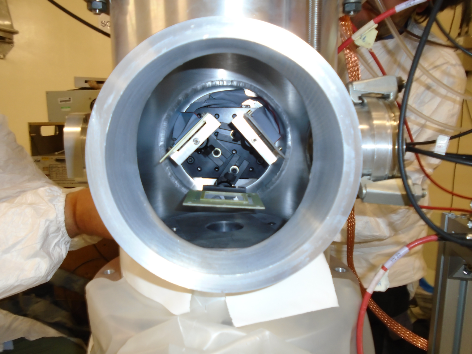
Claudia Lederer | Photos of Test Setup 5-10 October 2015 |
some photos in high resolution of the test setup 5-10 October 2015 |
| Attachment 1: DSC00042.JPG
|

|
| Attachment 2: DSC00048.JPG
|

|
| Attachment 3: DSC00056.JPG
|

|
| Attachment 4: DSC00065.JPG
|
|
|
57
|
Fri Aug 11 10:12:02 2023 |
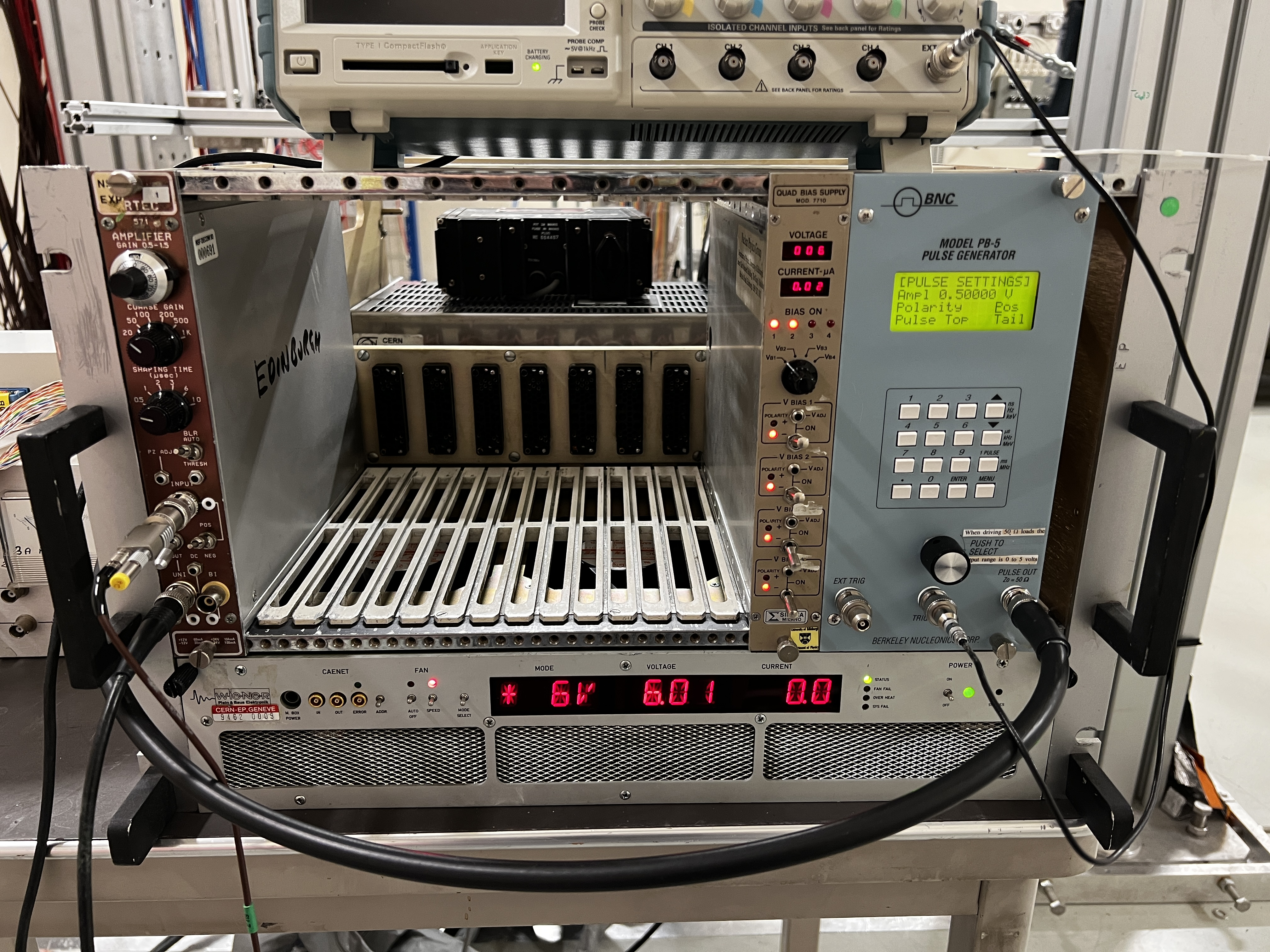
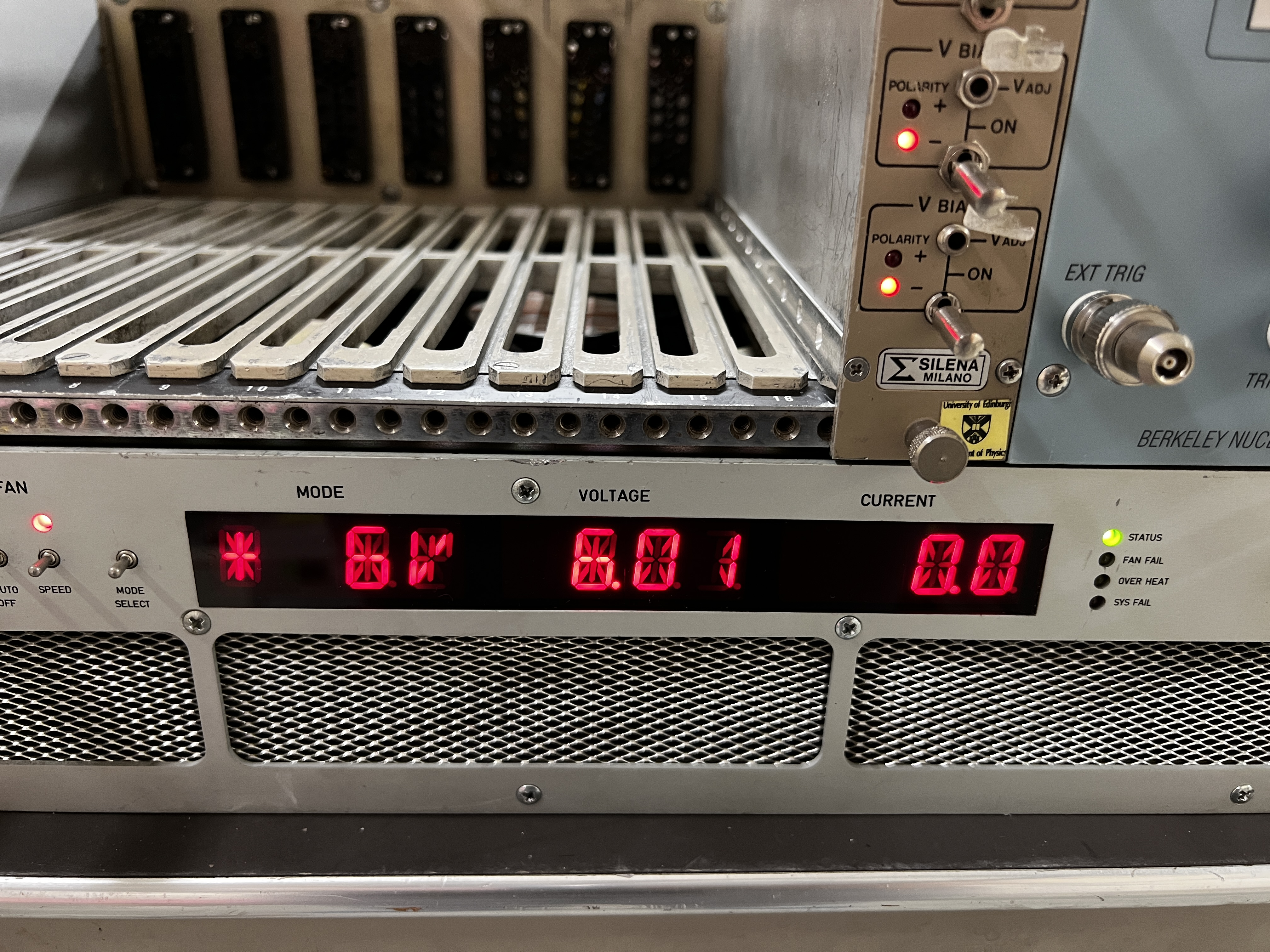
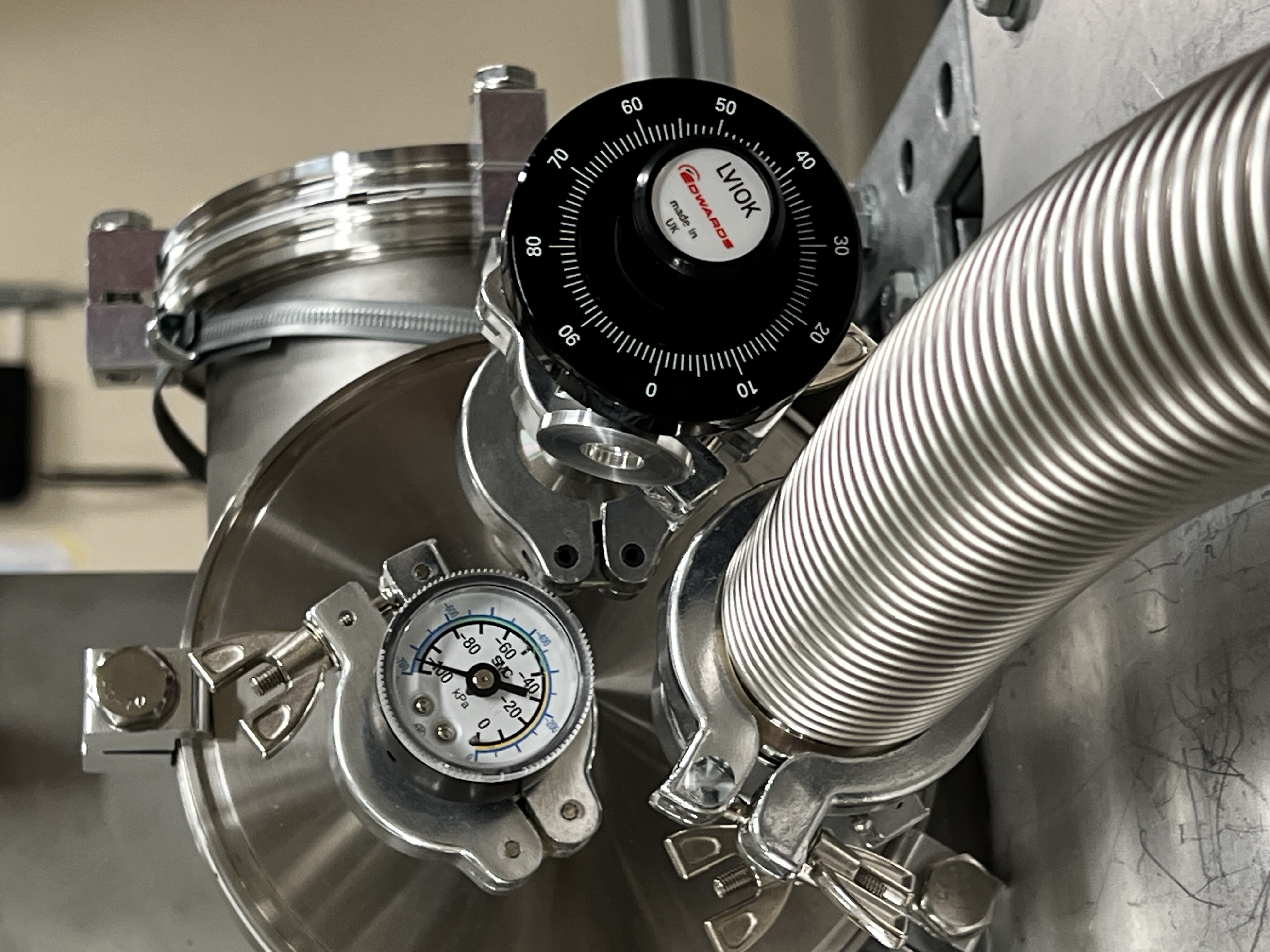
Annie | Pressure, voltage and current check |
|
| Attachment 1: IMG_2915.JPG
|
|
| Attachment 2: IMG_2916.JPG
|
|
| Attachment 3: IMG_2918.JPG
|
|
|
54
|
Fri Aug 11 09:11:04 2023 |
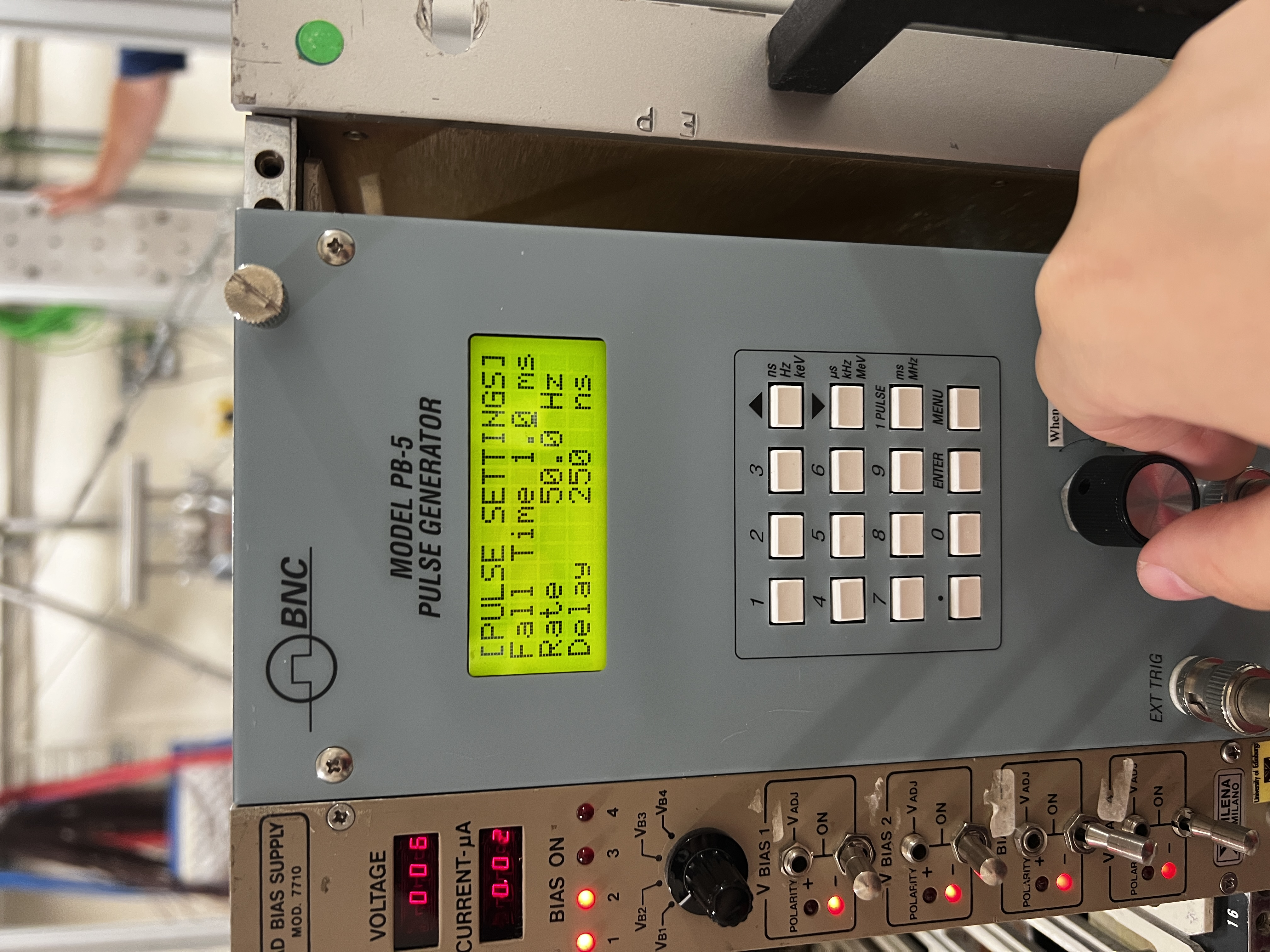
Annie | Pulse Settings |
|
| Attachment 1: IMG_2908.JPG
|

|
| Attachment 2: IMG_2909.JPG
|
|
| Attachment 3: IMG_2910.JPG
|

|
| Attachment 4: IMG_2911.JPG
|

|
|
66
|
Sat Aug 19 14:14:26 2023 |
TD | RAL108 +/-15V PSU test - JCMB 18.8.23 |
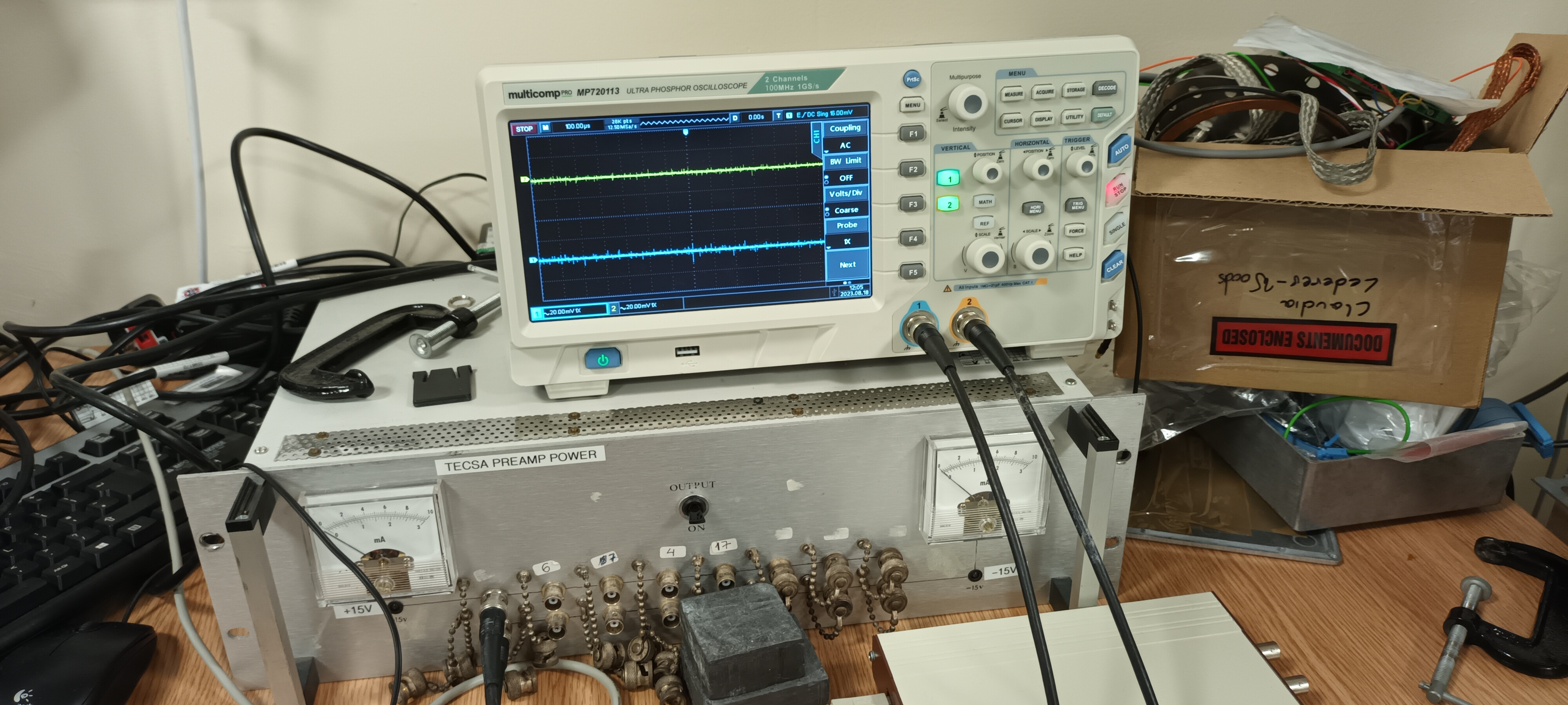
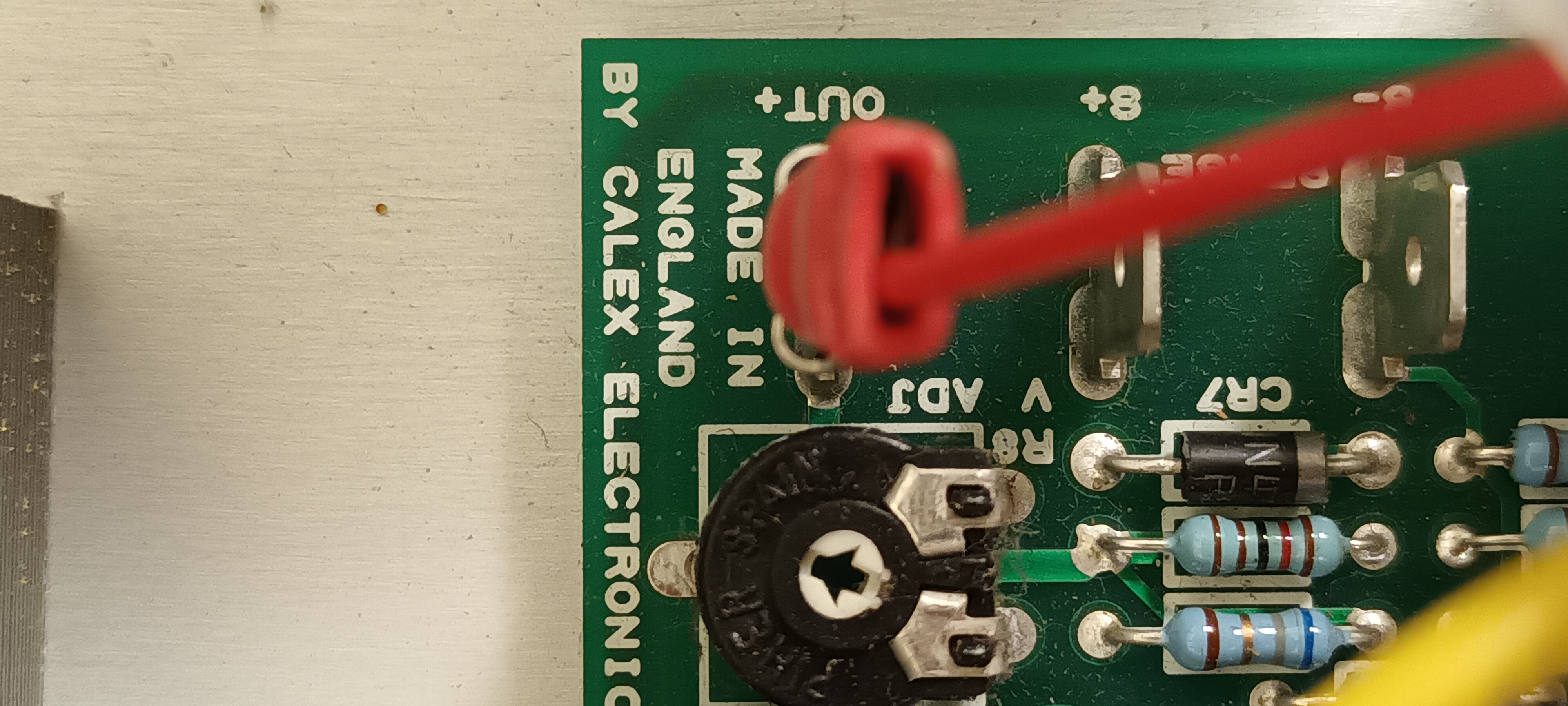
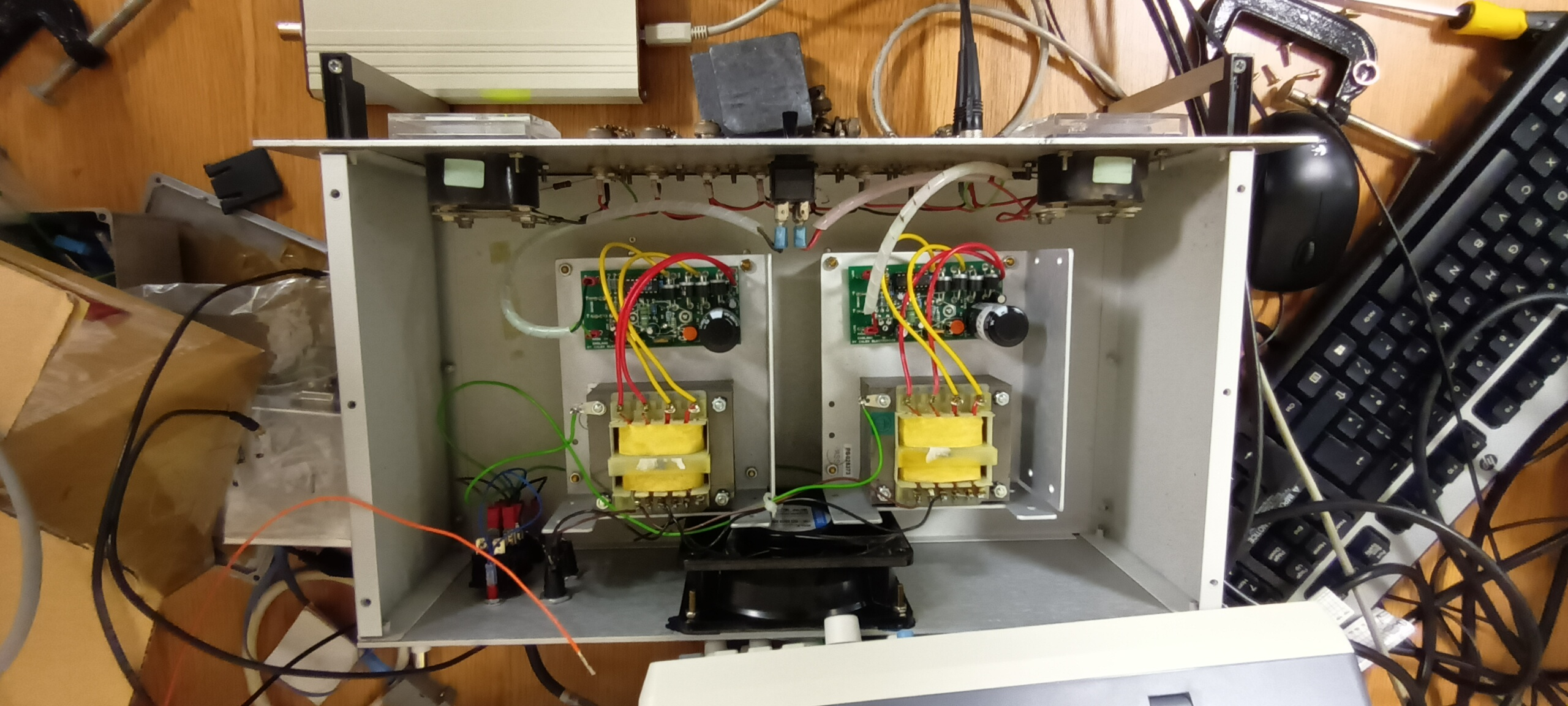
PSU Calex

Setup and PSU details - attachments 1-3

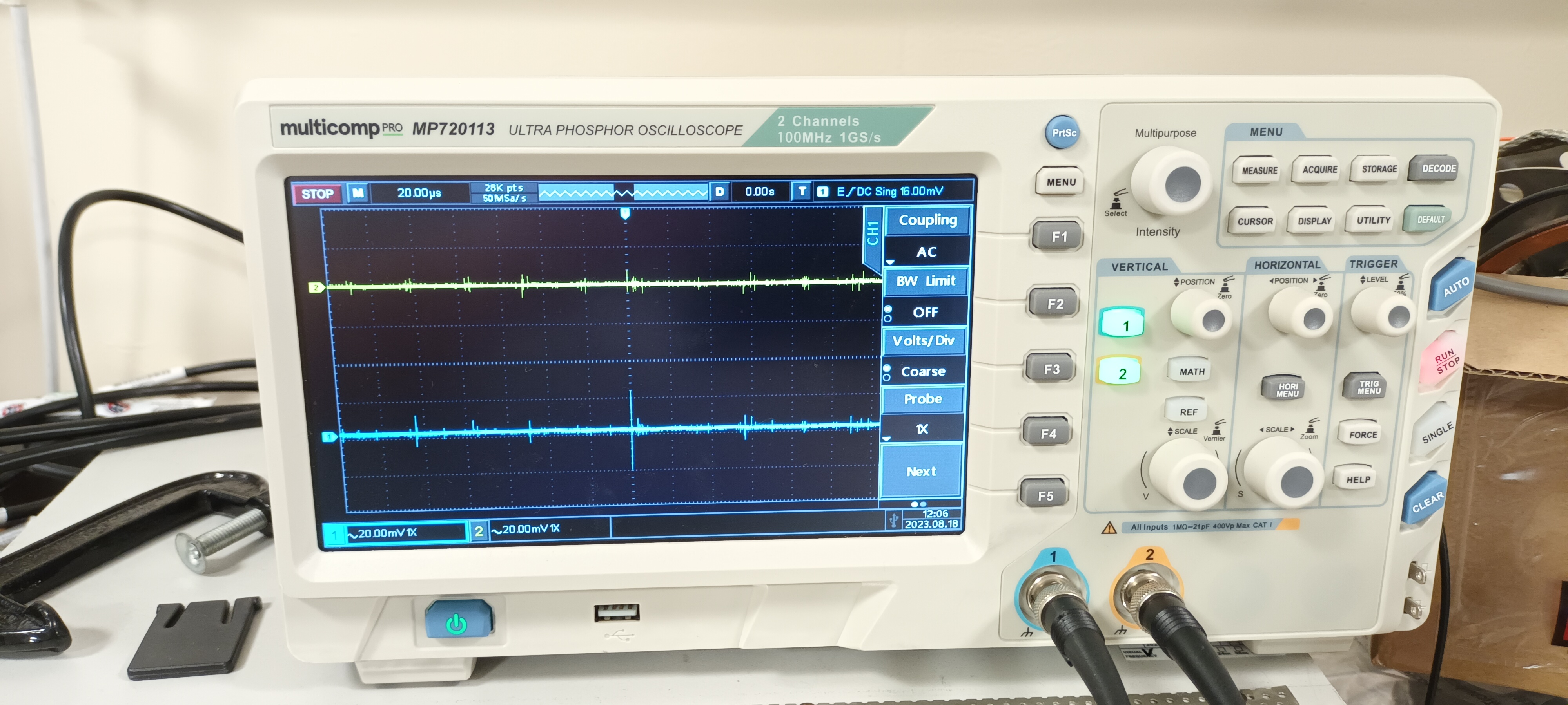
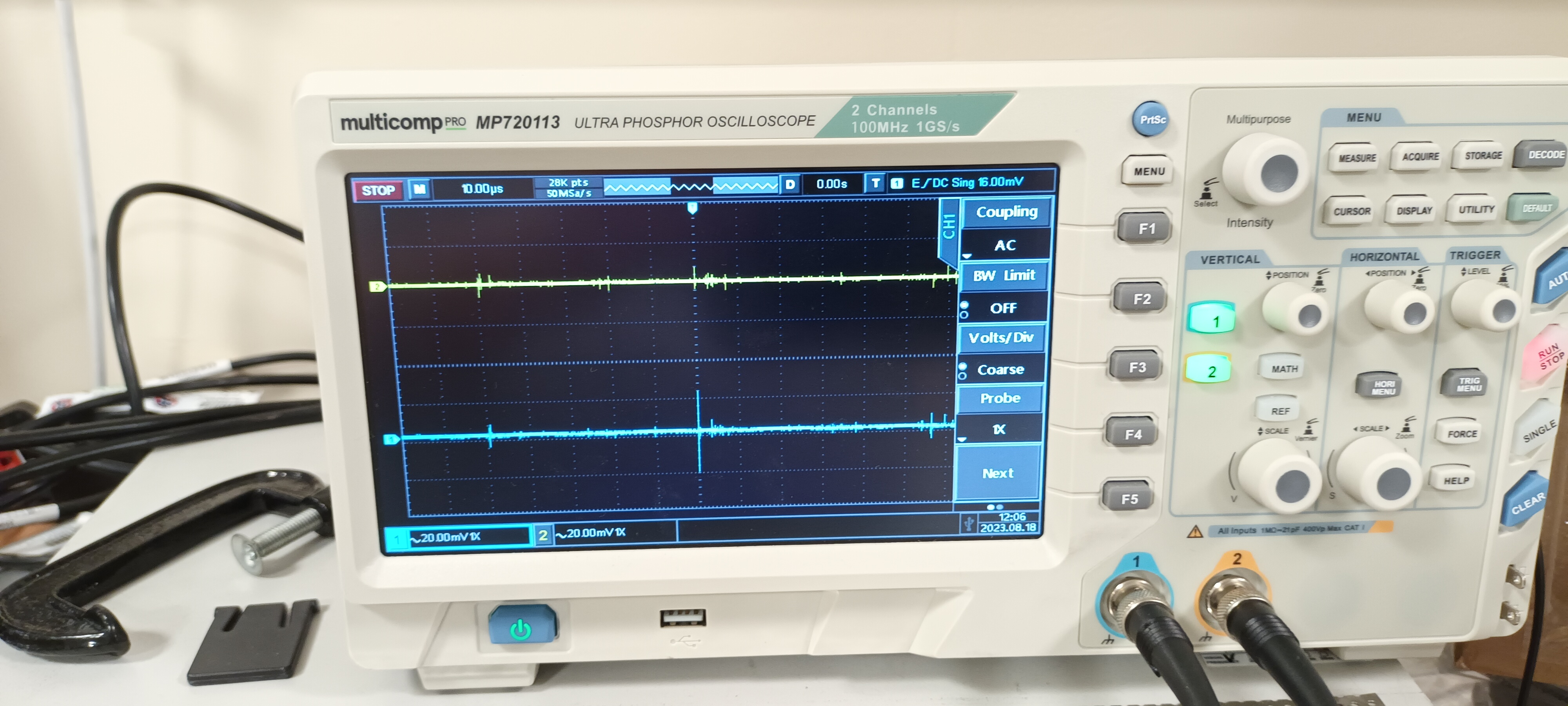
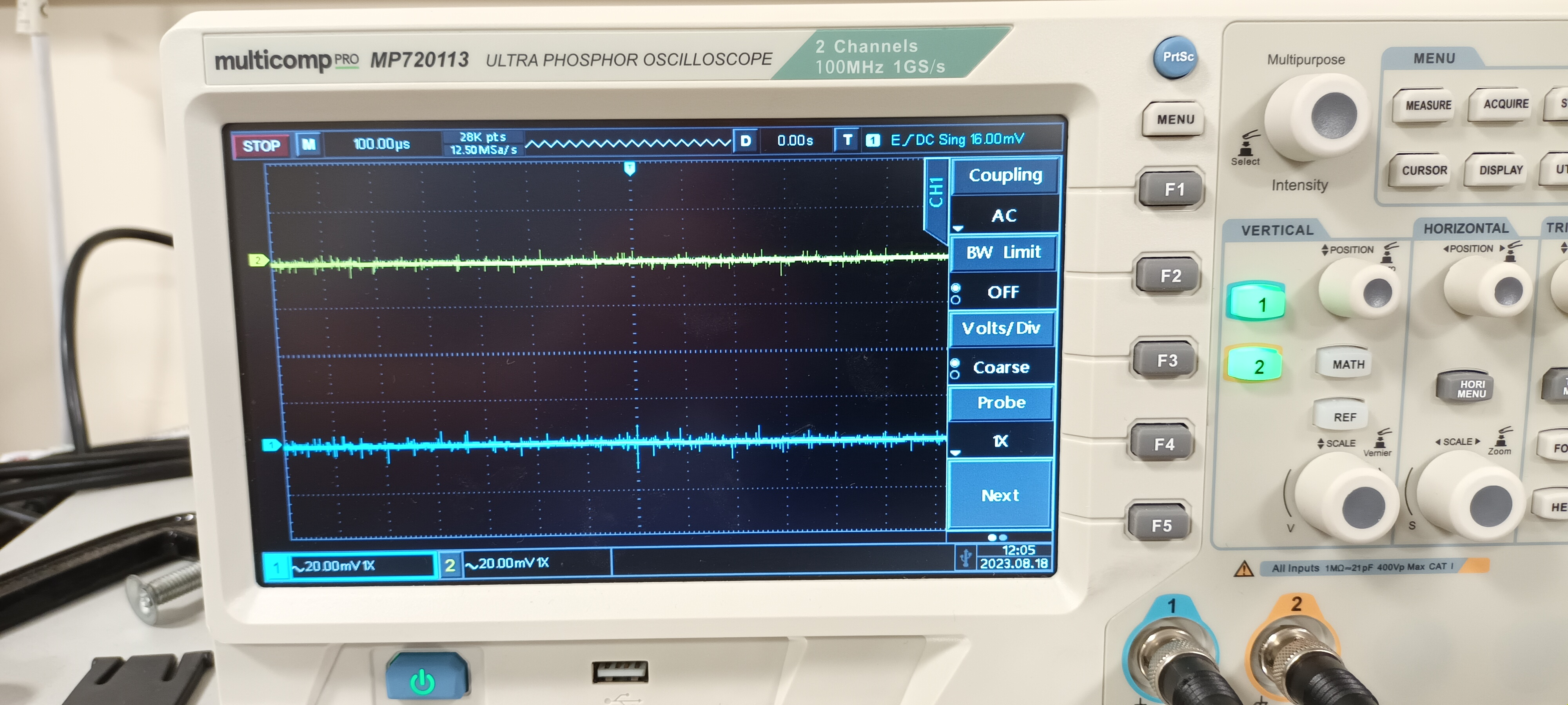
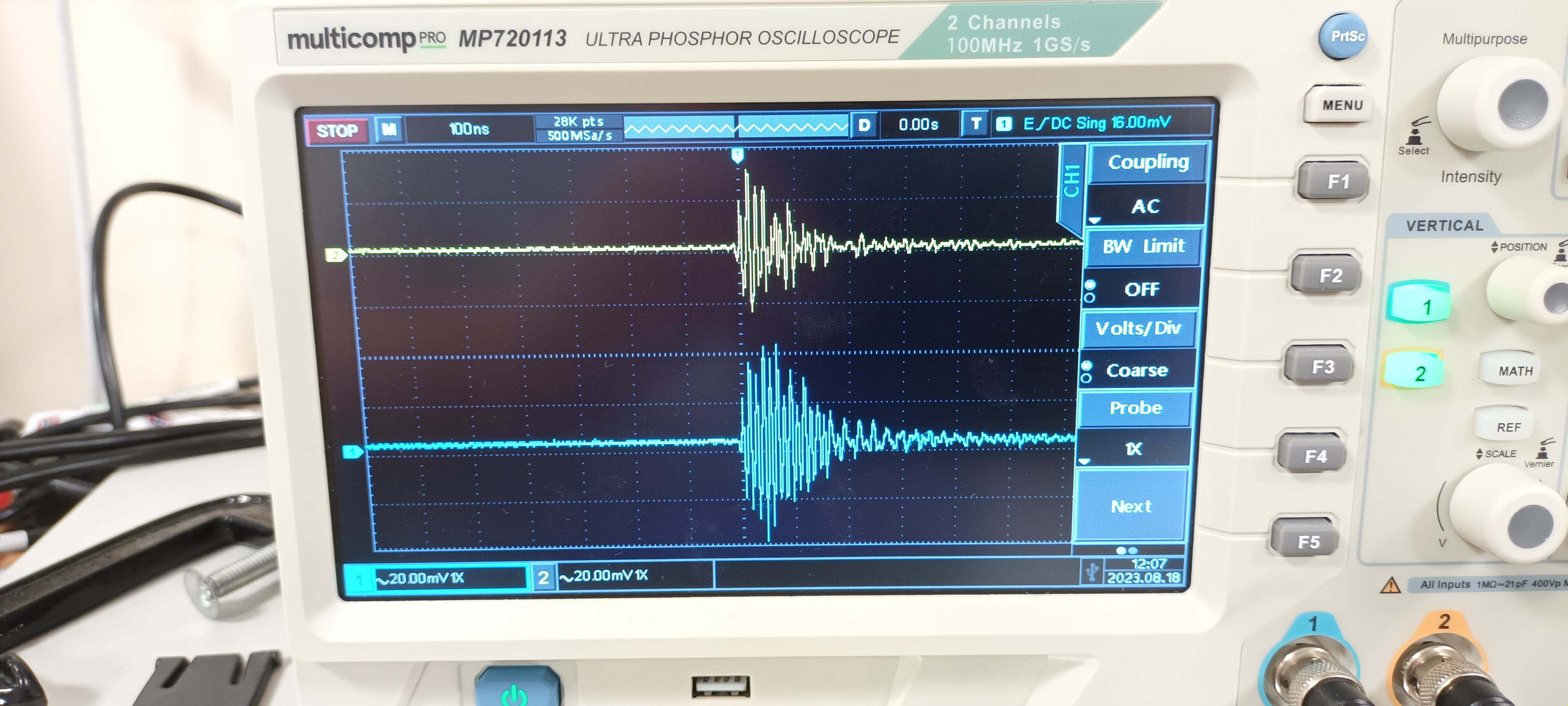
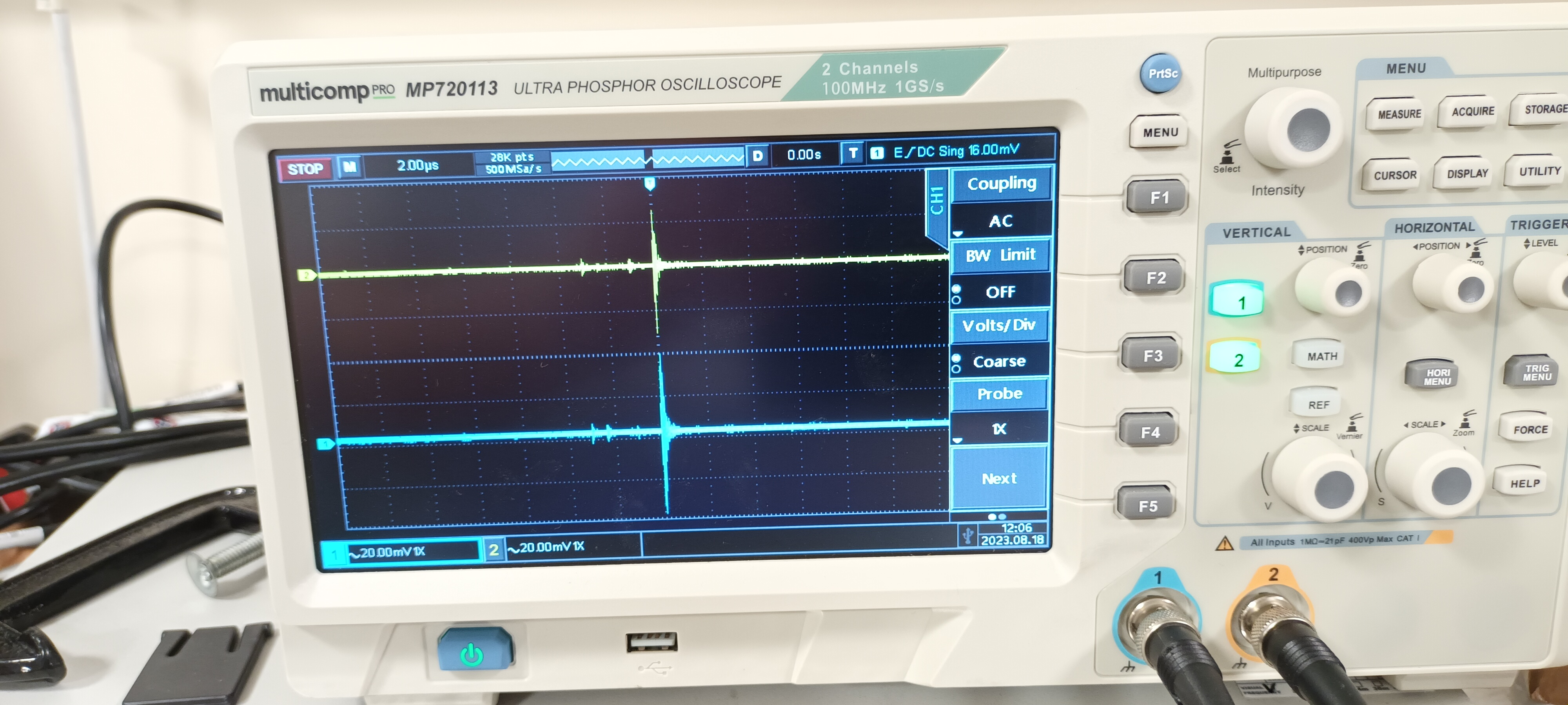
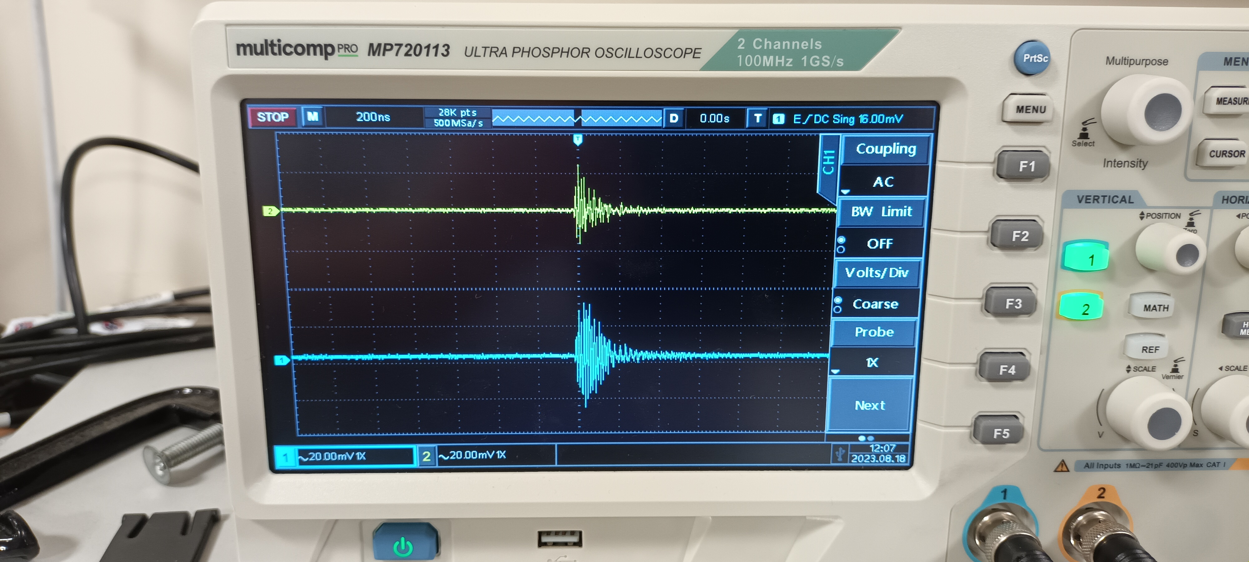
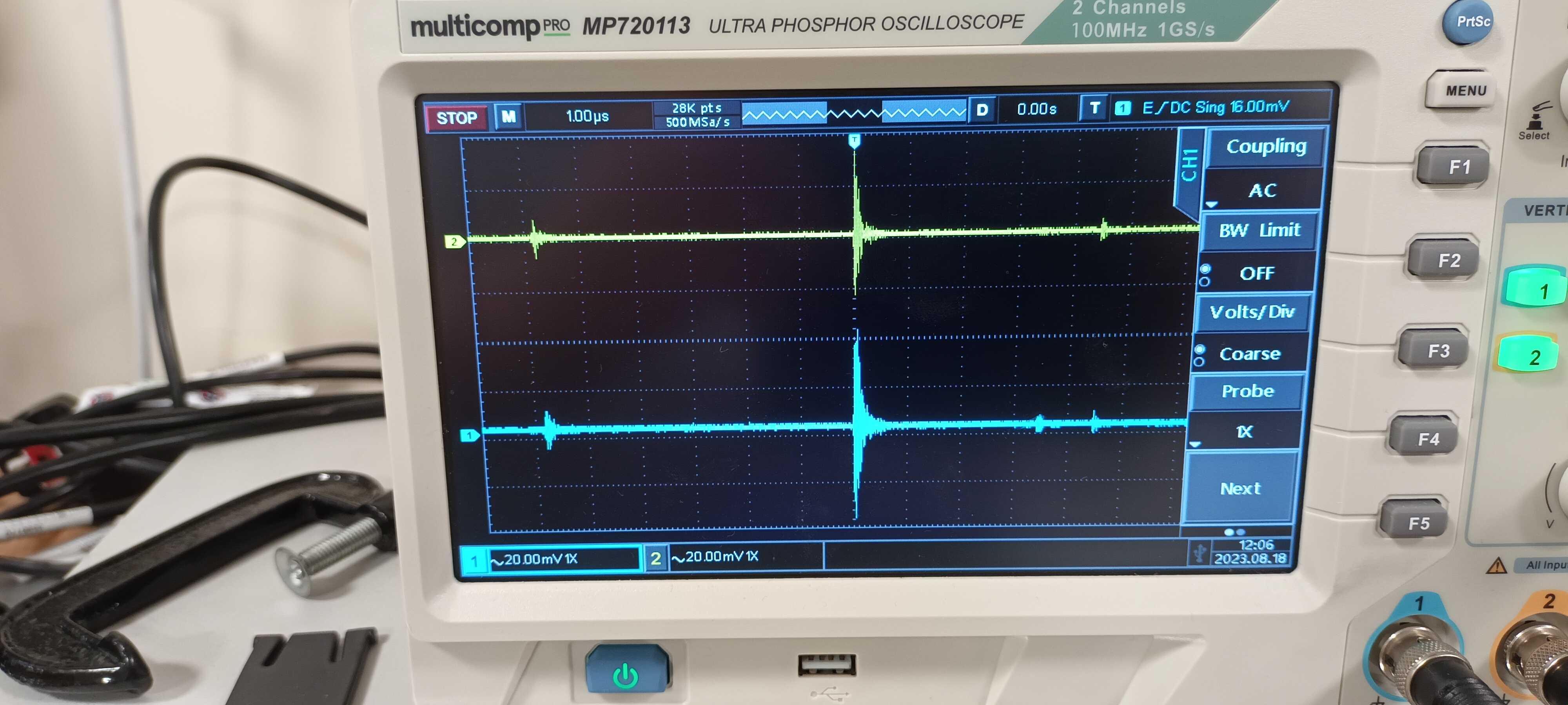
DSO ch#1 +15V AC/1M, ch#2 -15V AC/1M - y: 20mV/div x: 100ns, 200ns, 1us, 2us, 10us, 20us & 100us/div - attachments 4-10 |
| Attachment 1: 20230818_115256.jpg
|
|
| Attachment 2: 20230818_120358.jpg
|
|
| Attachment 3: 20230818_120127.jpg
|
|
| Attachment 4: 20230818_115311.jpg
|
|
| Attachment 5: 20230818_115329.jpg
|
|
| Attachment 6: 20230818_115250.jpg
|
|
| Attachment 7: 20230818_115421.jpg
|
|
| Attachment 8: 20230818_115341.jpg
|
|
| Attachment 9: 20230818_115409.jpg
|
|
| Attachment 10: 20230818_115352.jpg
|
|
|
67
|
Mon Aug 21 12:08:59 2023 |
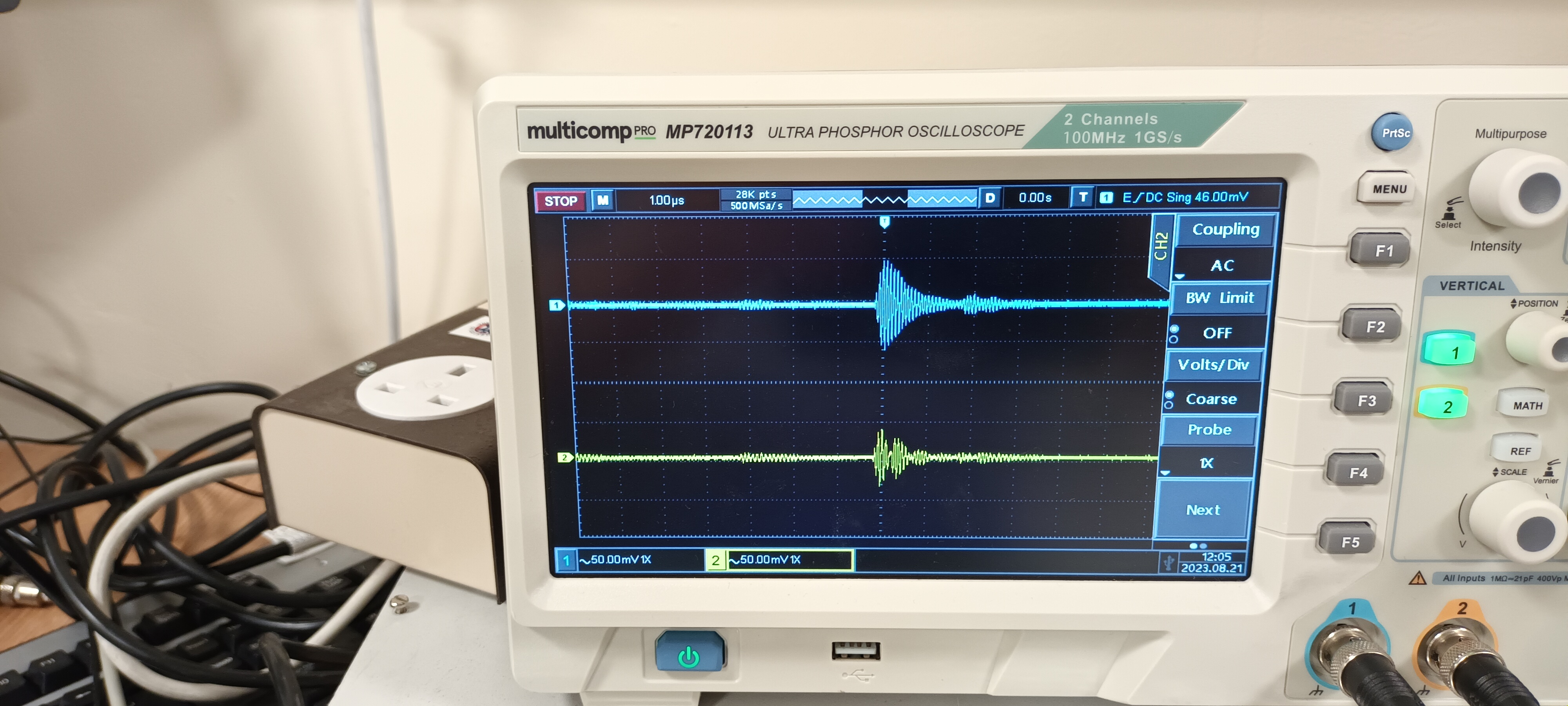
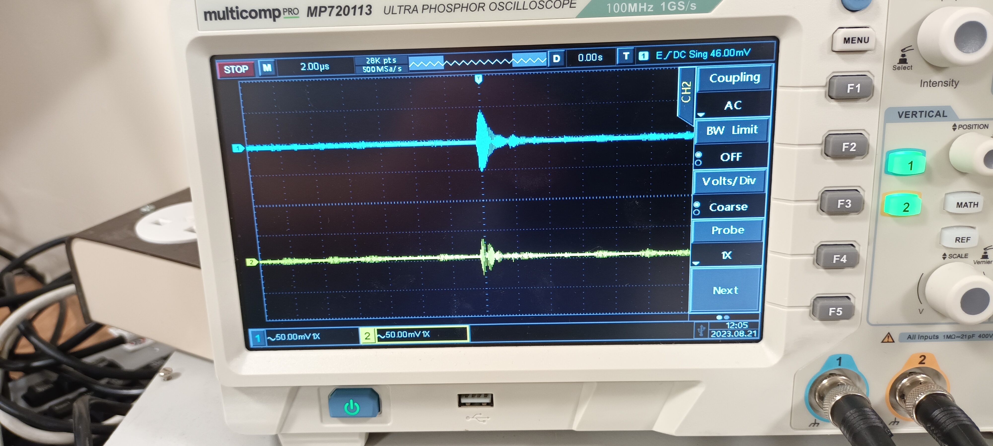
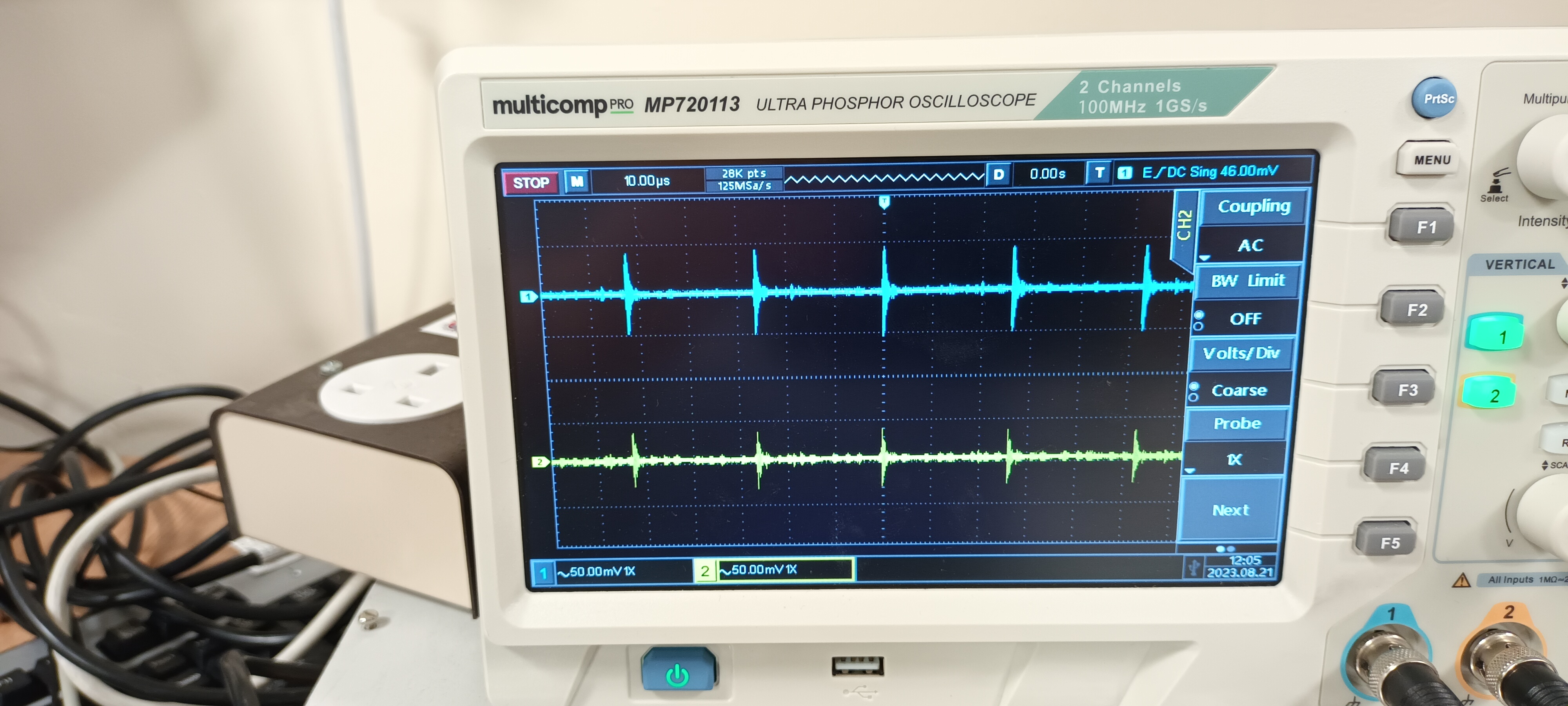
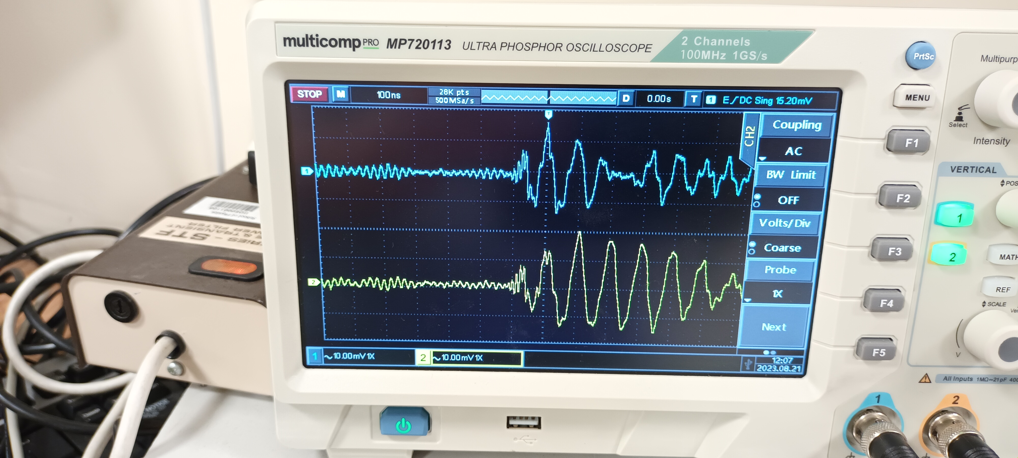
TD | RAL108 +/-15V PSU test - JCMB 21.8.23 |
PSU Calex

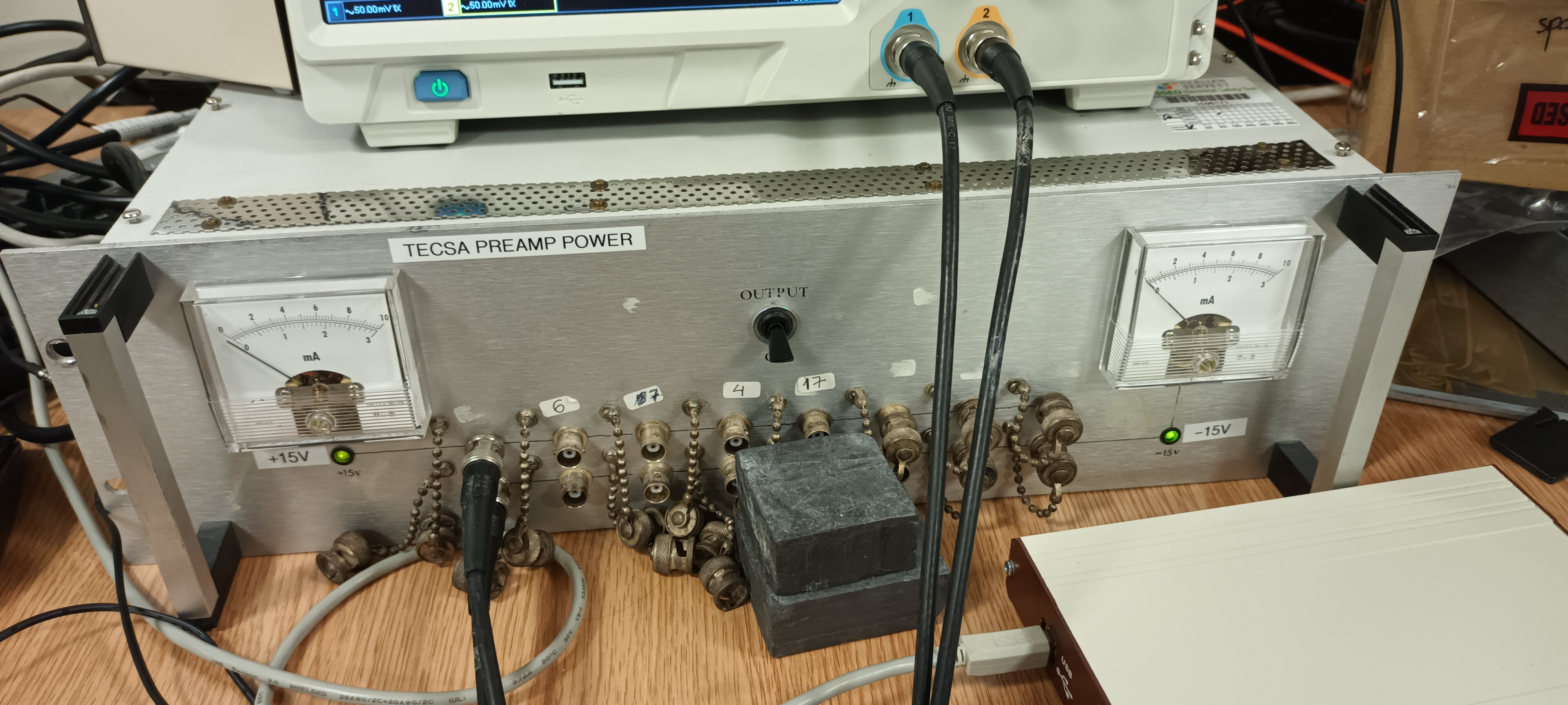
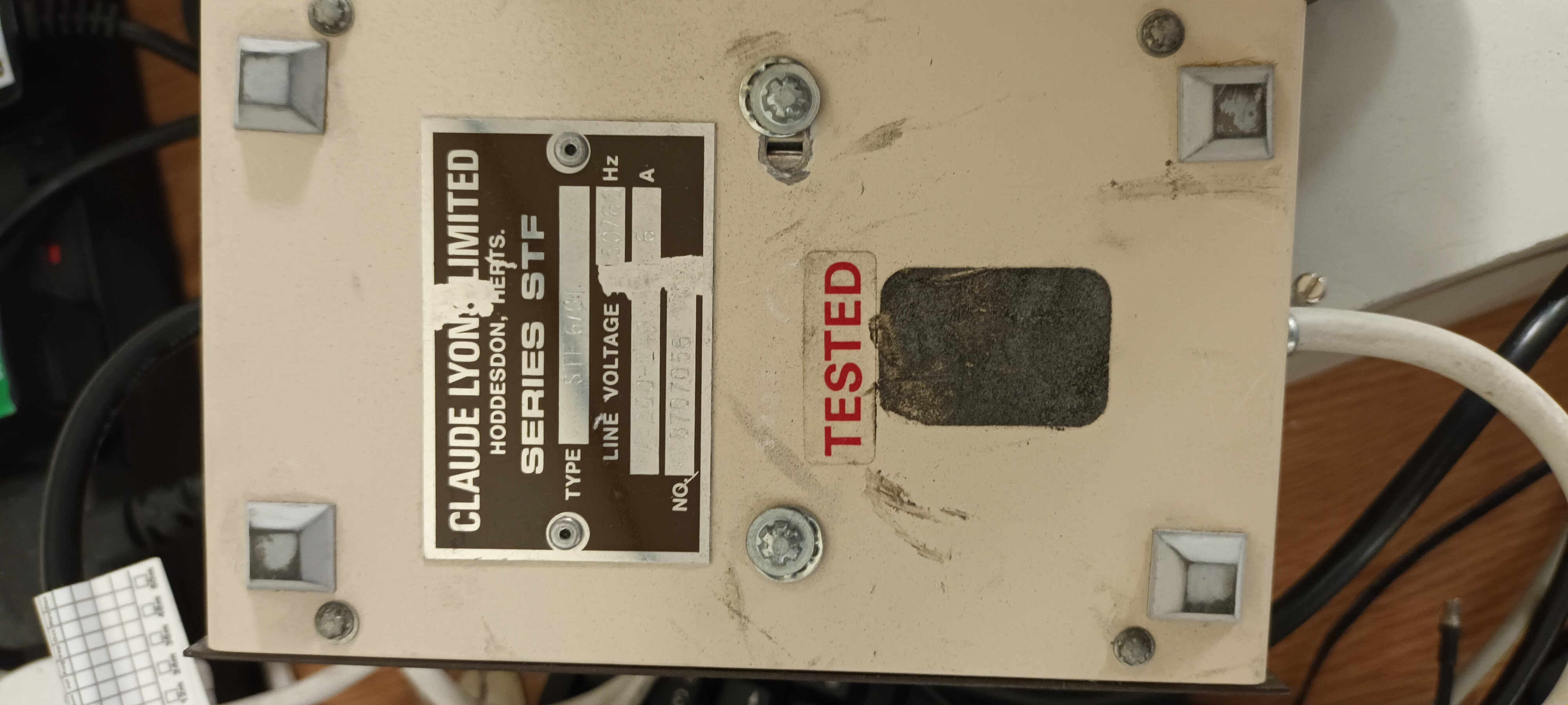
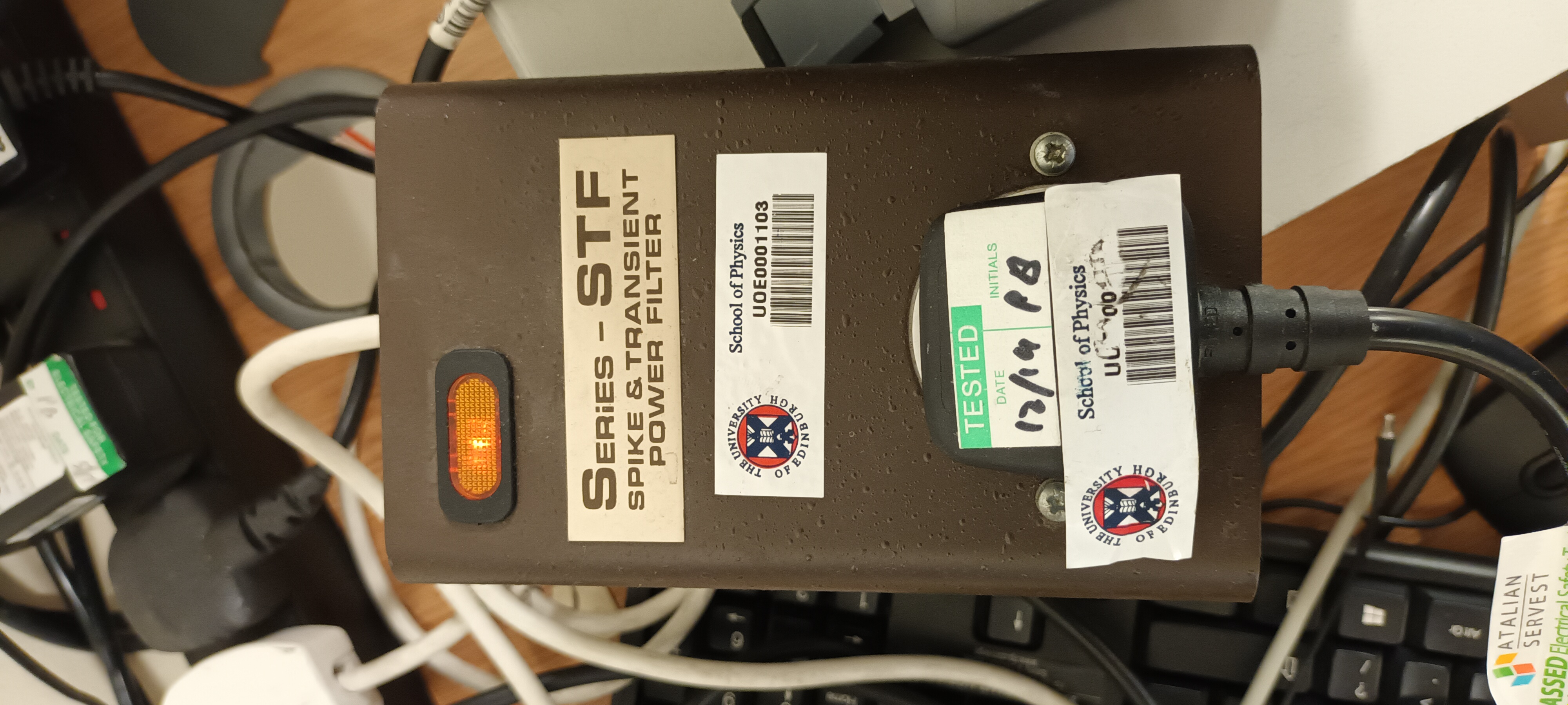
Setup, PSU and ac mains filter - attachments 1-3


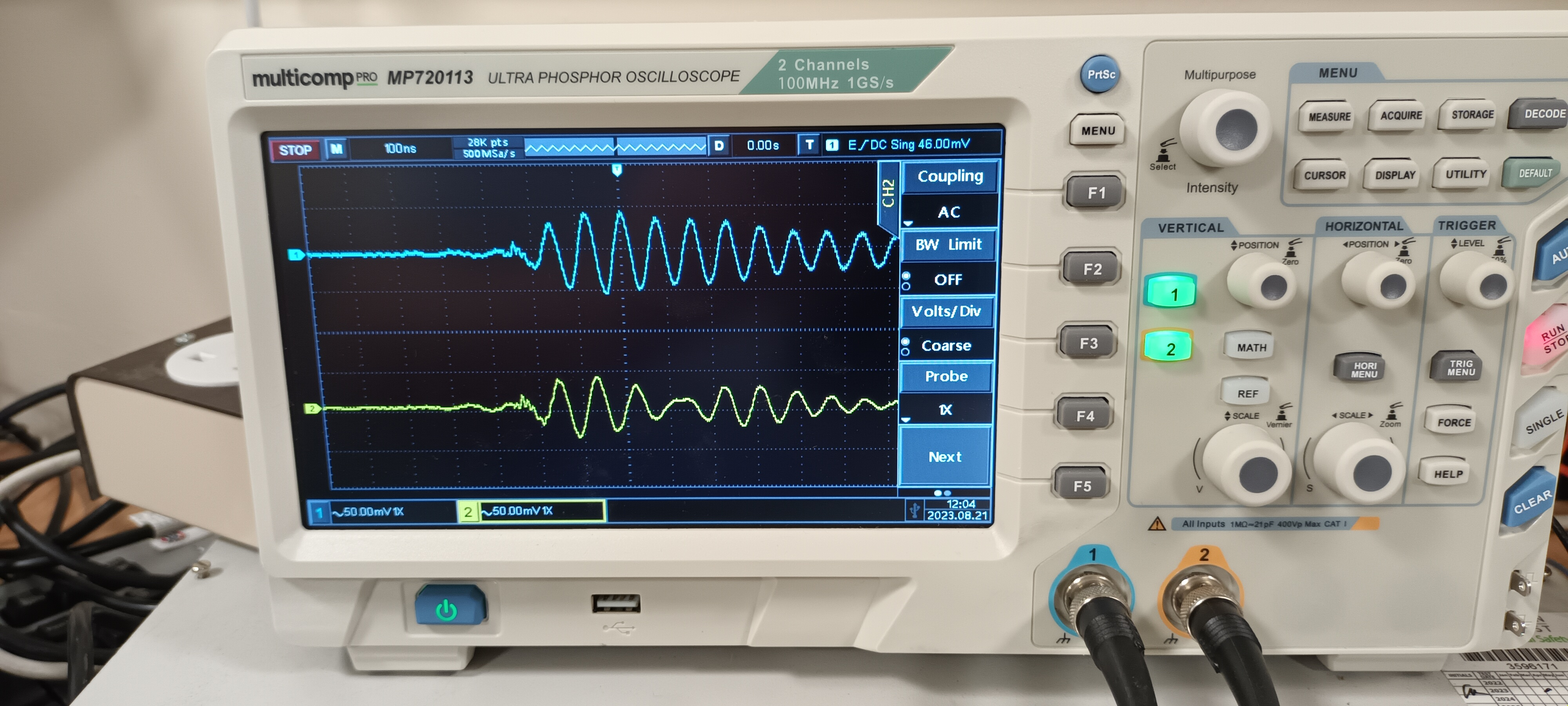
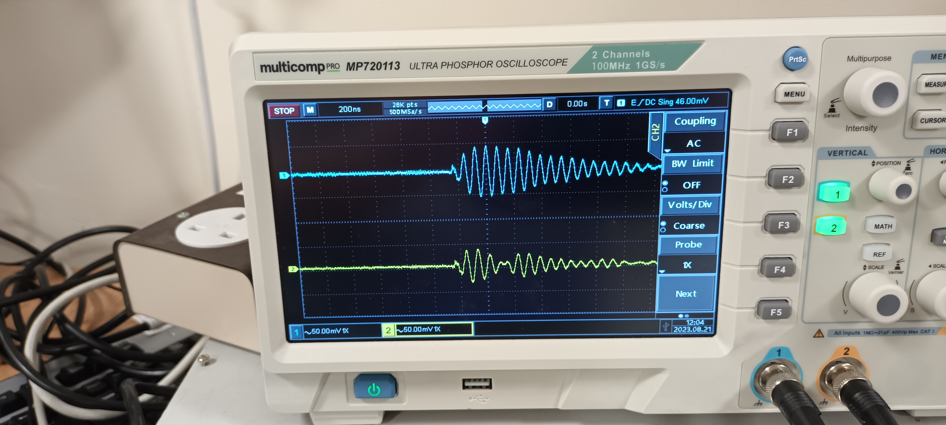
DSO ch#1 +15V AC/1M, ch#2 -15V AC/1M - y: 50mV/div x: 100ns, 200ns, 1us, 2us, 10us/div

Without ac mains filter - attachments 4-8


DSO ch#1 +15V AC/1M, ch#2 -15V AC/1M - y: 10mV/div x: 100ns, 200ns, 1us, 2us, 10us/div

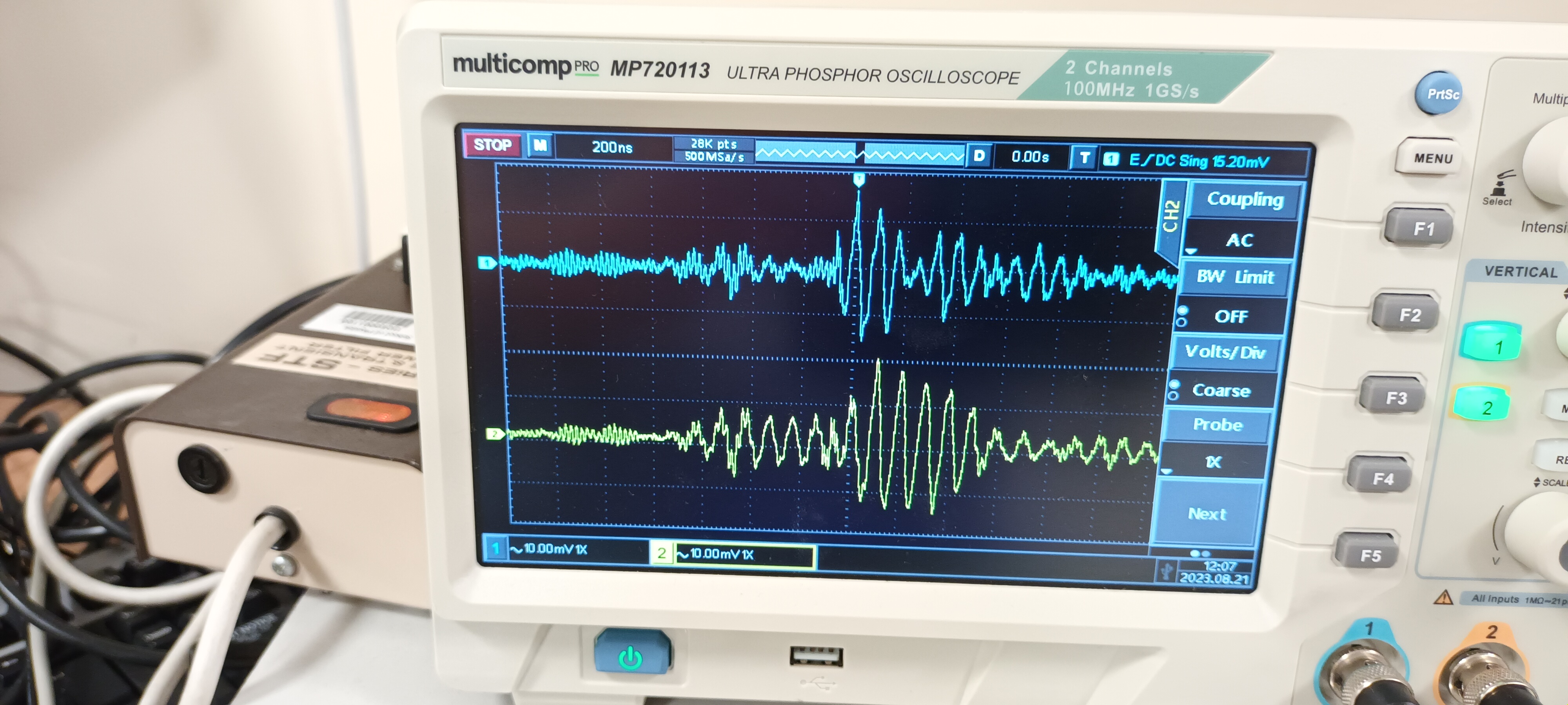
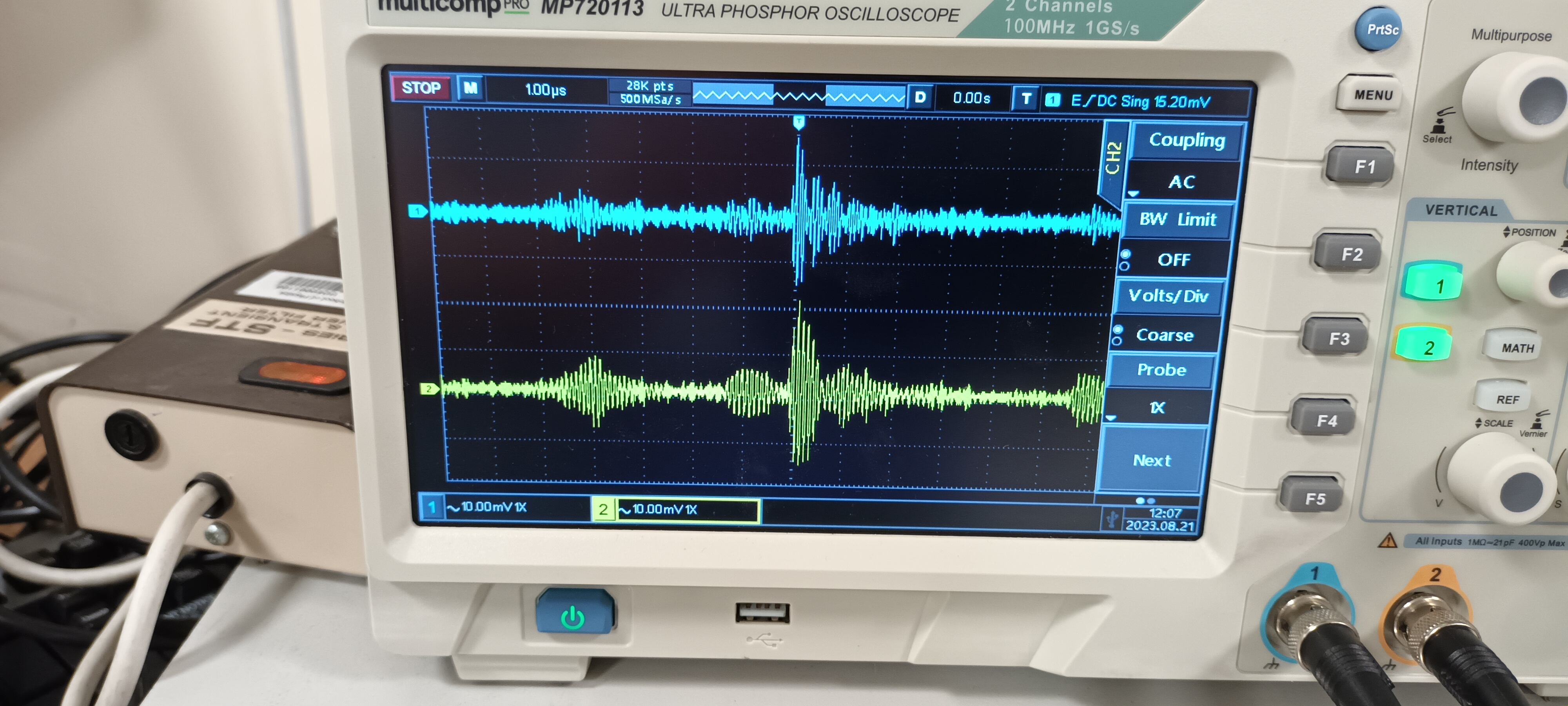
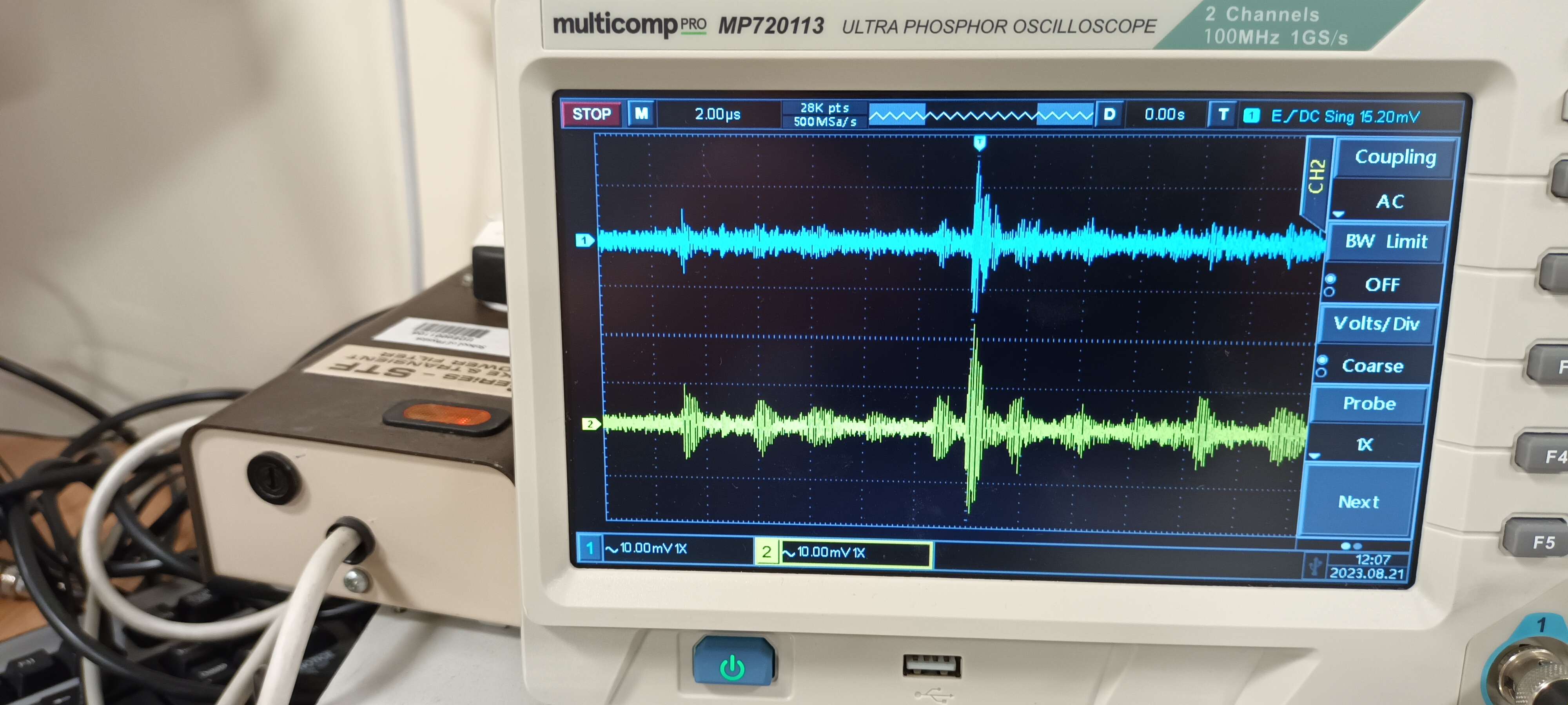
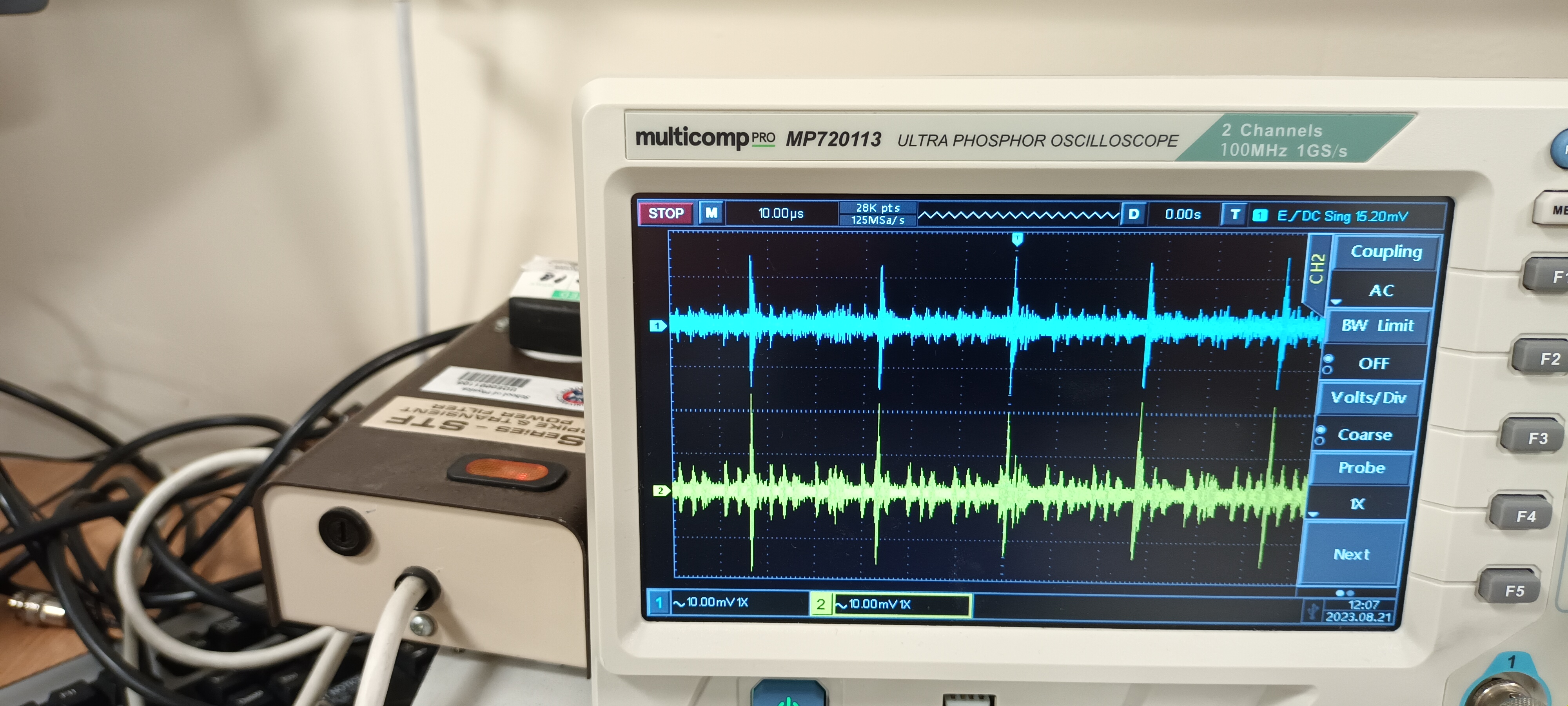
With ac mains filter - attachments 9-13

Conclusion - Claud Lyons Ltd STF Series Surge & Transient Power Filter produces c. x 2 attenuation of HF noise transients |
| Attachment 1: 20230821_115139.jpg
|
|
| Attachment 2: 20230821_115314.jpg
|
|
| Attachment 3: 20230821_115259.jpg
|
|
| Attachment 4: 20230821_115144.jpg
|
|
| Attachment 5: 20230821_115156.jpg
|
|
| Attachment 6: 20230821_115206.jpg
|
|
| Attachment 7: 20230821_115216.jpg
|
|
| Attachment 8: 20230821_115229.jpg
|
|
| Attachment 9: 20230821_115415.jpg
|
|
| Attachment 10: 20230821_115424.jpg
|
|
| Attachment 11: 20230821_115438.jpg
|
|
| Attachment 12: 20230821_115447.jpg
|
|
| Attachment 13: 20230821_115457.jpg
|
|
|
63
|
Tue Aug 15 10:17:39 2023 |
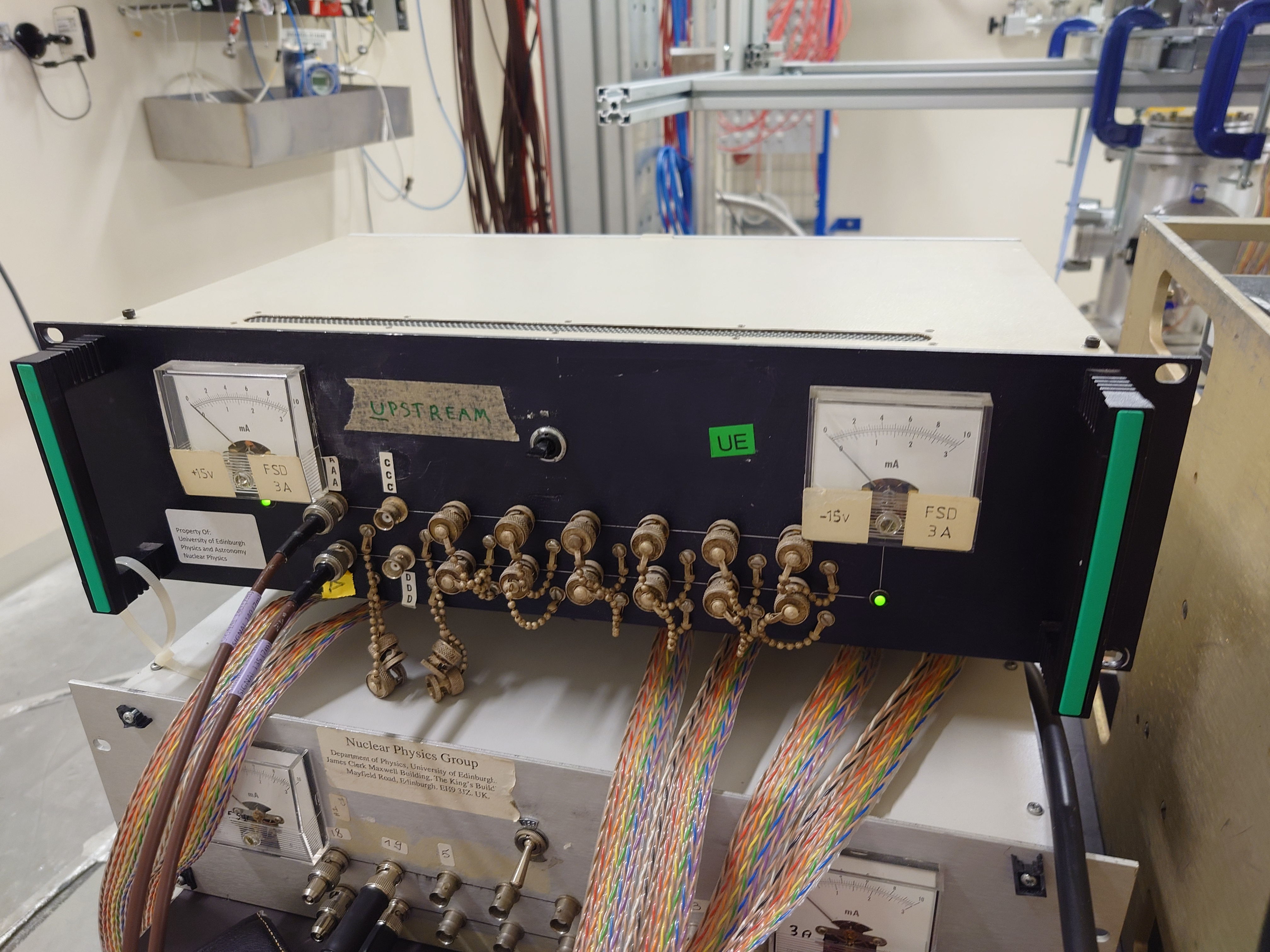
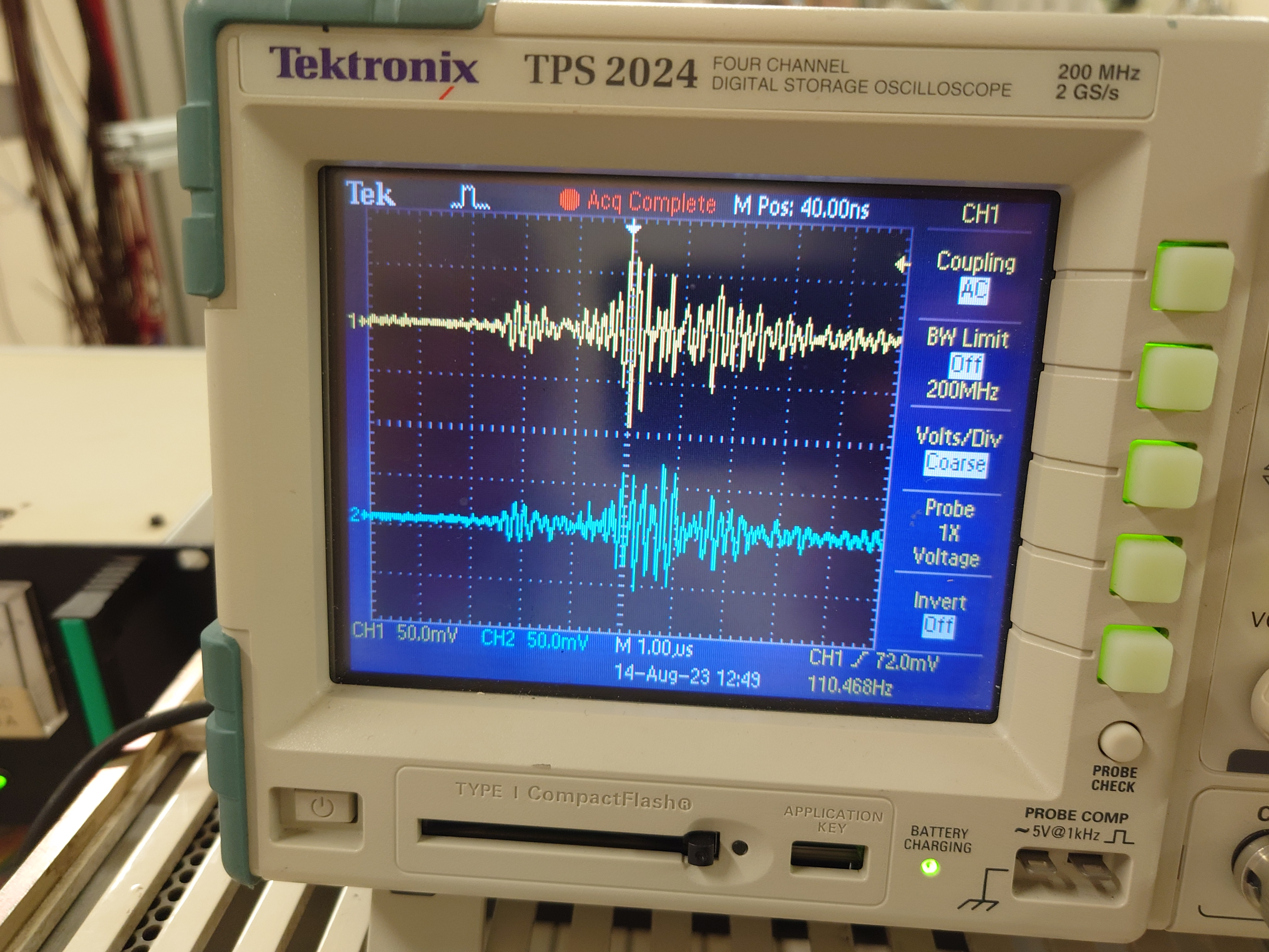
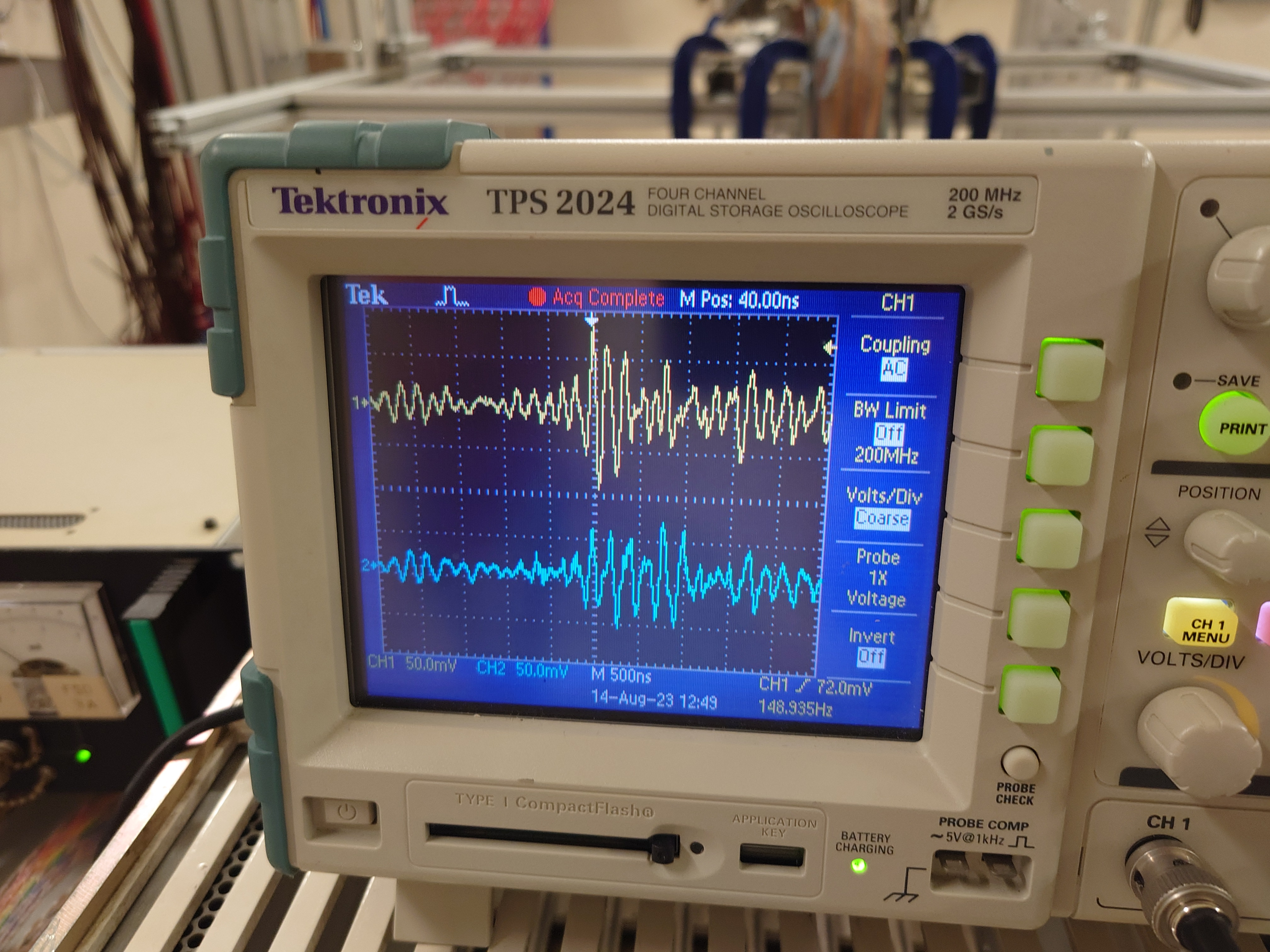
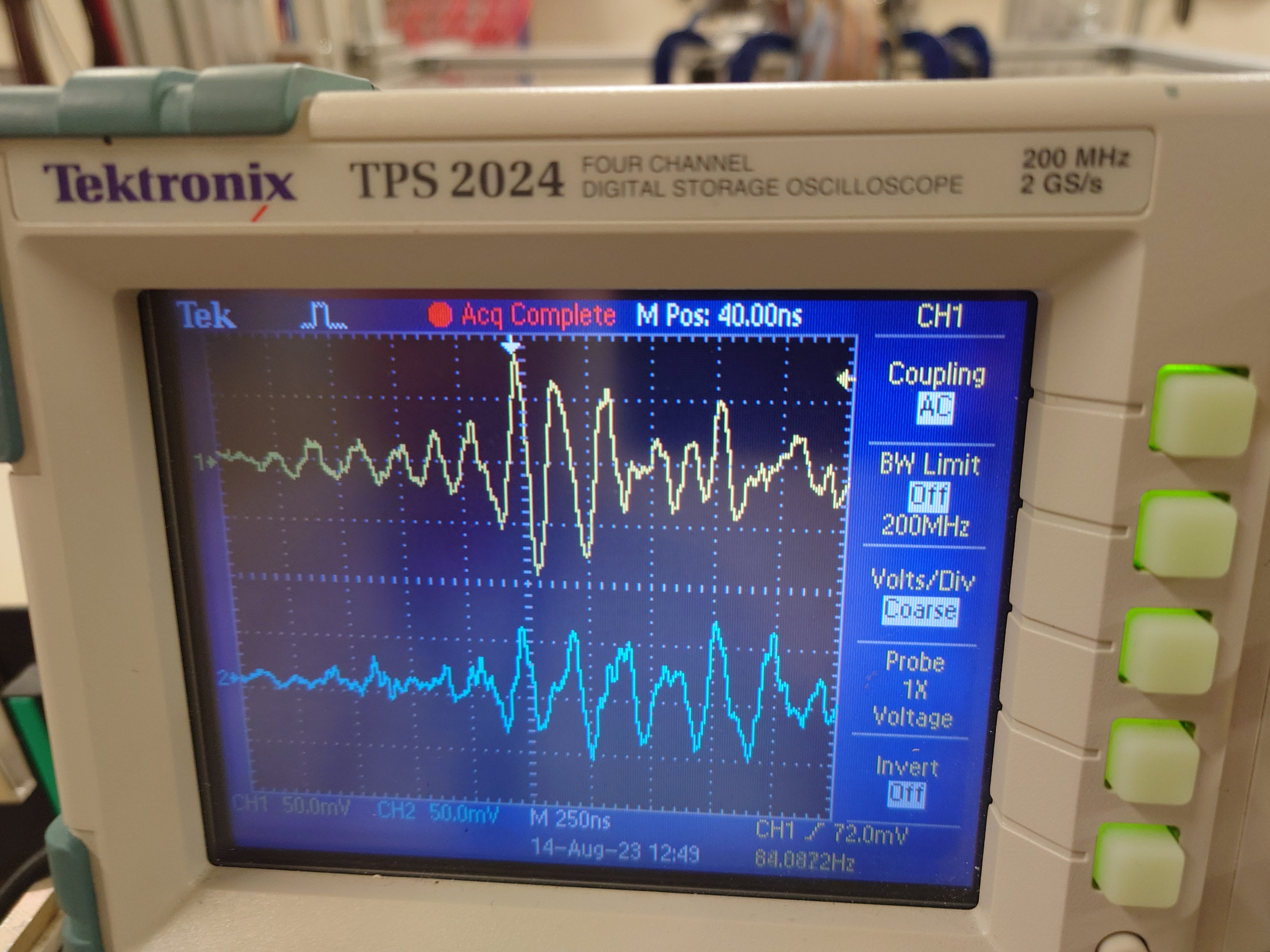
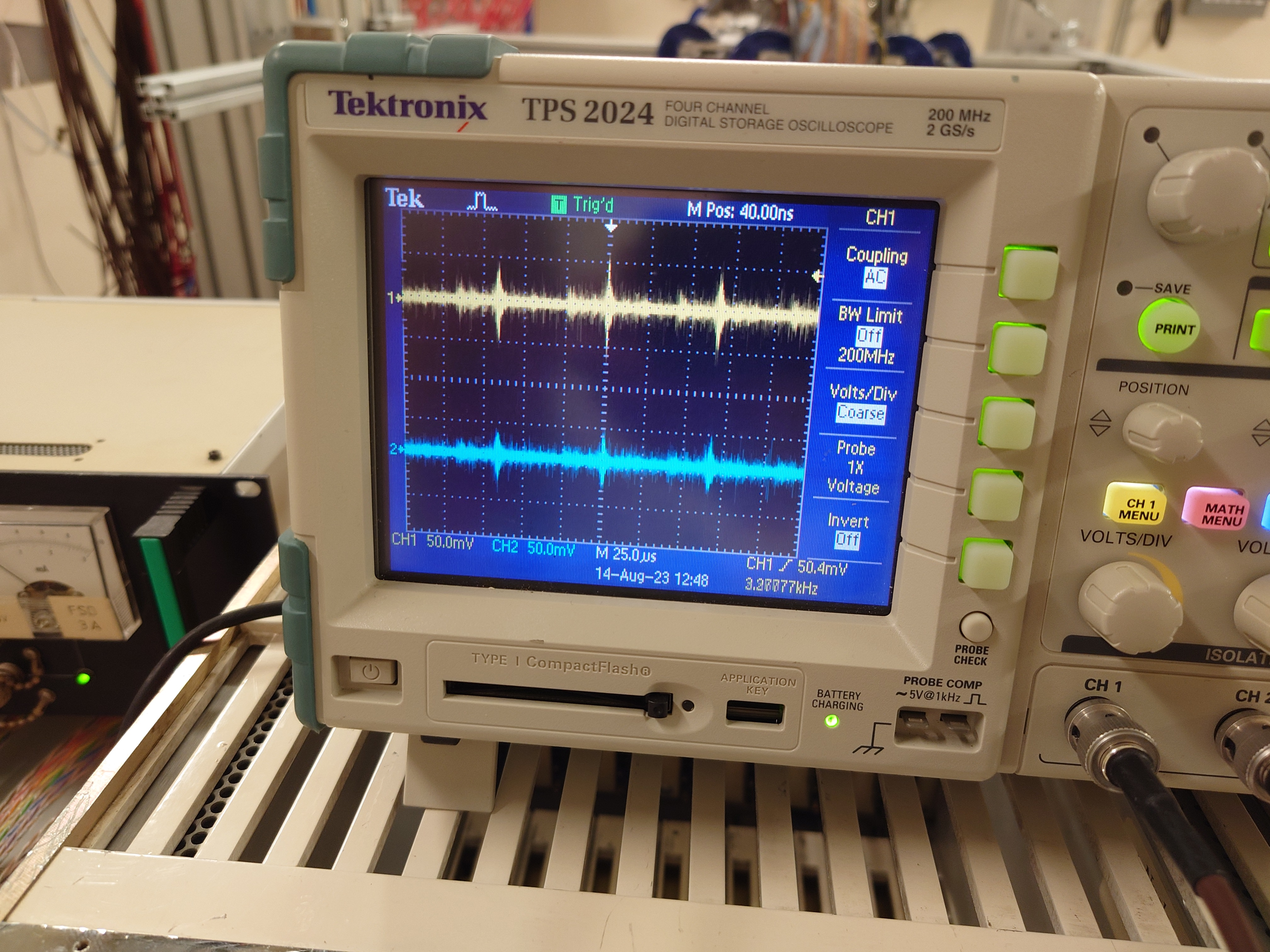
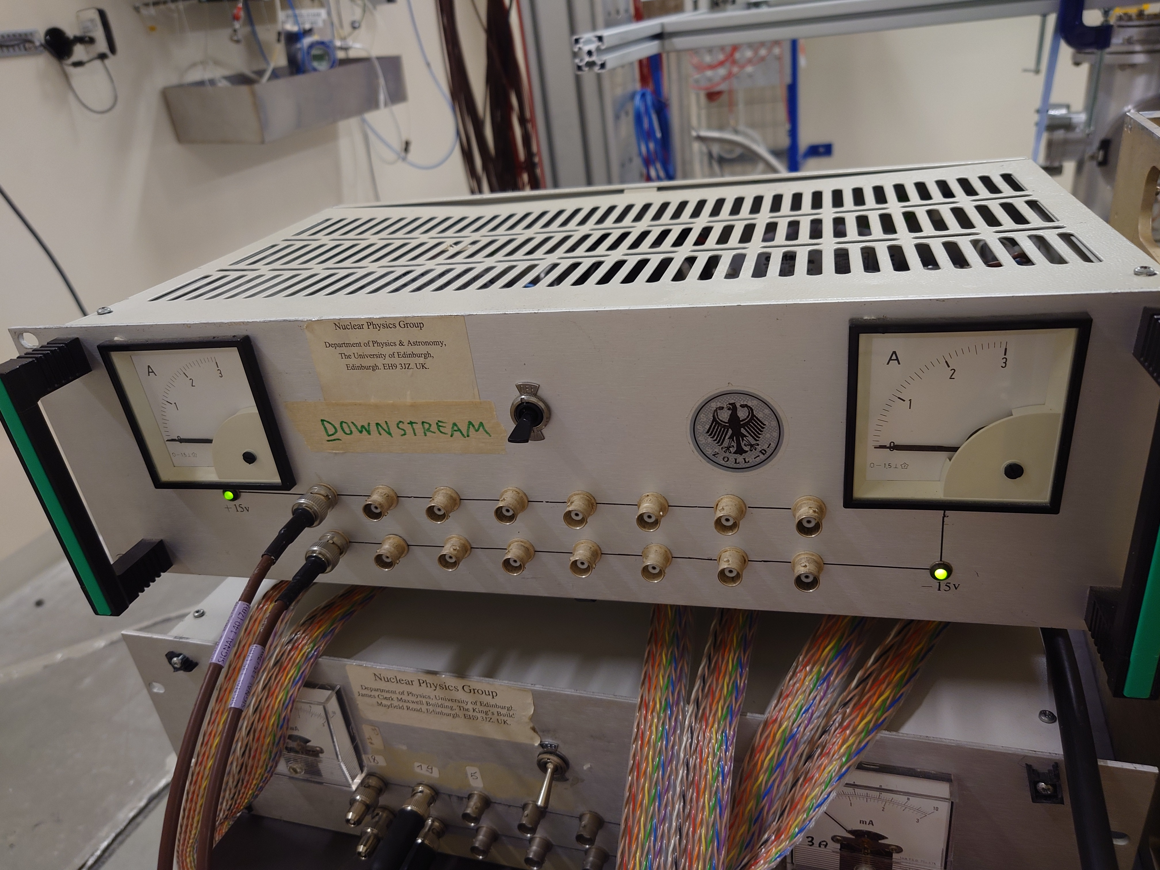
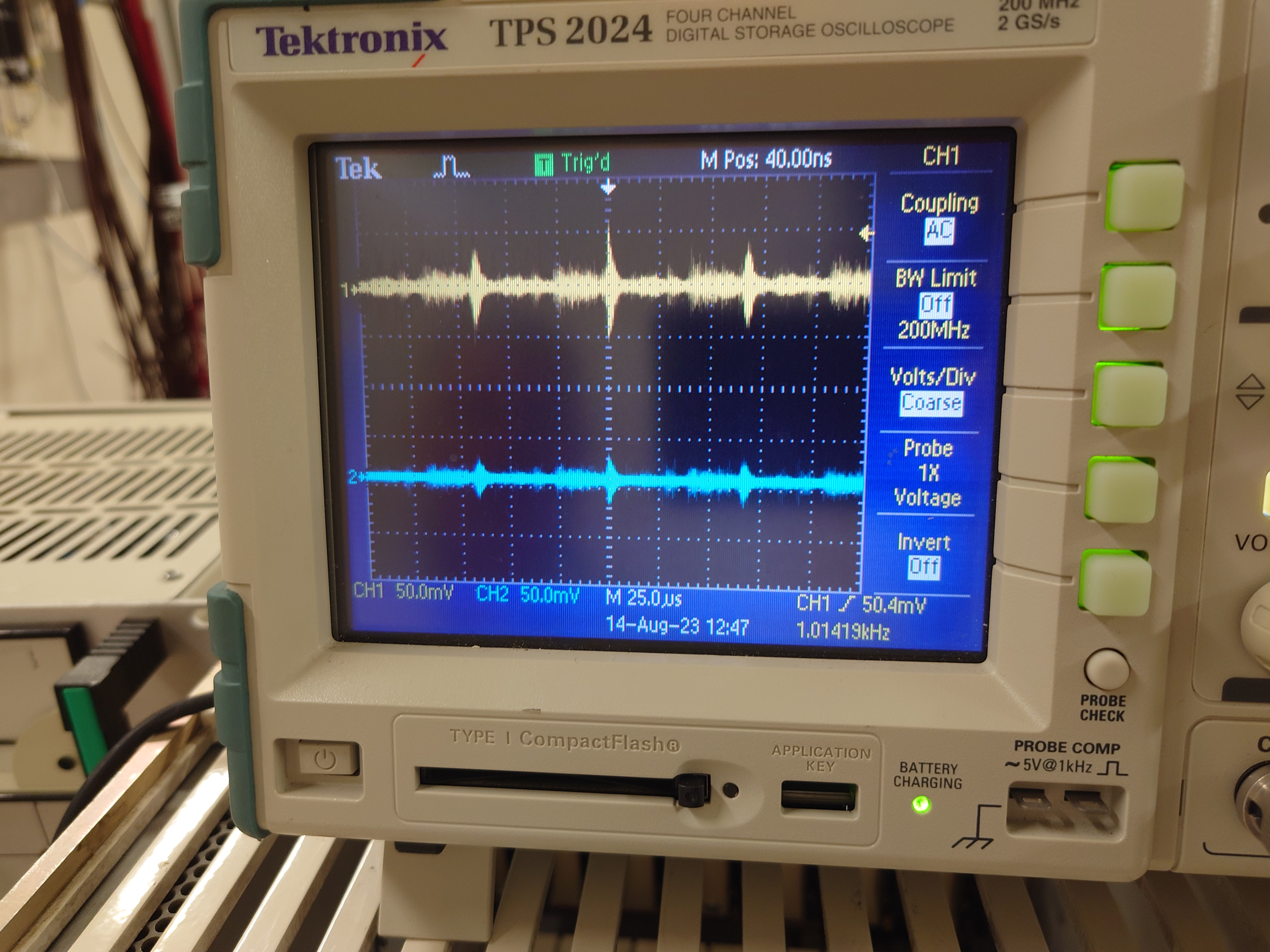
TD, NS | RAL108 +/-15V PSU test at EAR2, n_TOF Monday 14 August |
On the morning of Monday 14 August 2x RAL108 +/-15V PSUs were borrowed from the Edinburgh equipment in the ISOLDE hall to check whether the same transient
noise is observed at the +/-15V PSU outputs.


PSU #2 Farnell MX2

Setup - attachment 1

DSO ch#1 +15V AC/1M, ch#2 -15V AC/1M - y: 50mV/div x: 1us, 500ns, 250ns & 25us/div - attachments 2-5


PSU #1 Coutant HSC15-3.0

Setup - attachment 6

DSO ch#1 +15V AC/1M, ch#2 -15V AC/1M - y: 50mV/div x: 25us/div - attachment 7


Conclusion

Observe same amplitude and HF structure with all 3x RAL108 +/-15V PSUs |
| Attachment 1: 20230814_083448.jpg
|
|
| Attachment 2: 20230814_083549.jpg
|
|
| Attachment 3: 20230814_083556.jpg
|
|
| Attachment 4: 20230814_083601.jpg
|
|
| Attachment 5: 20230814_083445.jpg
|
|
| Attachment 6: 20230814_083323.jpg
|
|
| Attachment 7: 20230814_083319.jpg
|
|
|
62
|
Mon Aug 14 11:00:13 2023 |
TD | RAL108 +/-15V PSU test in ISOLDE hall |
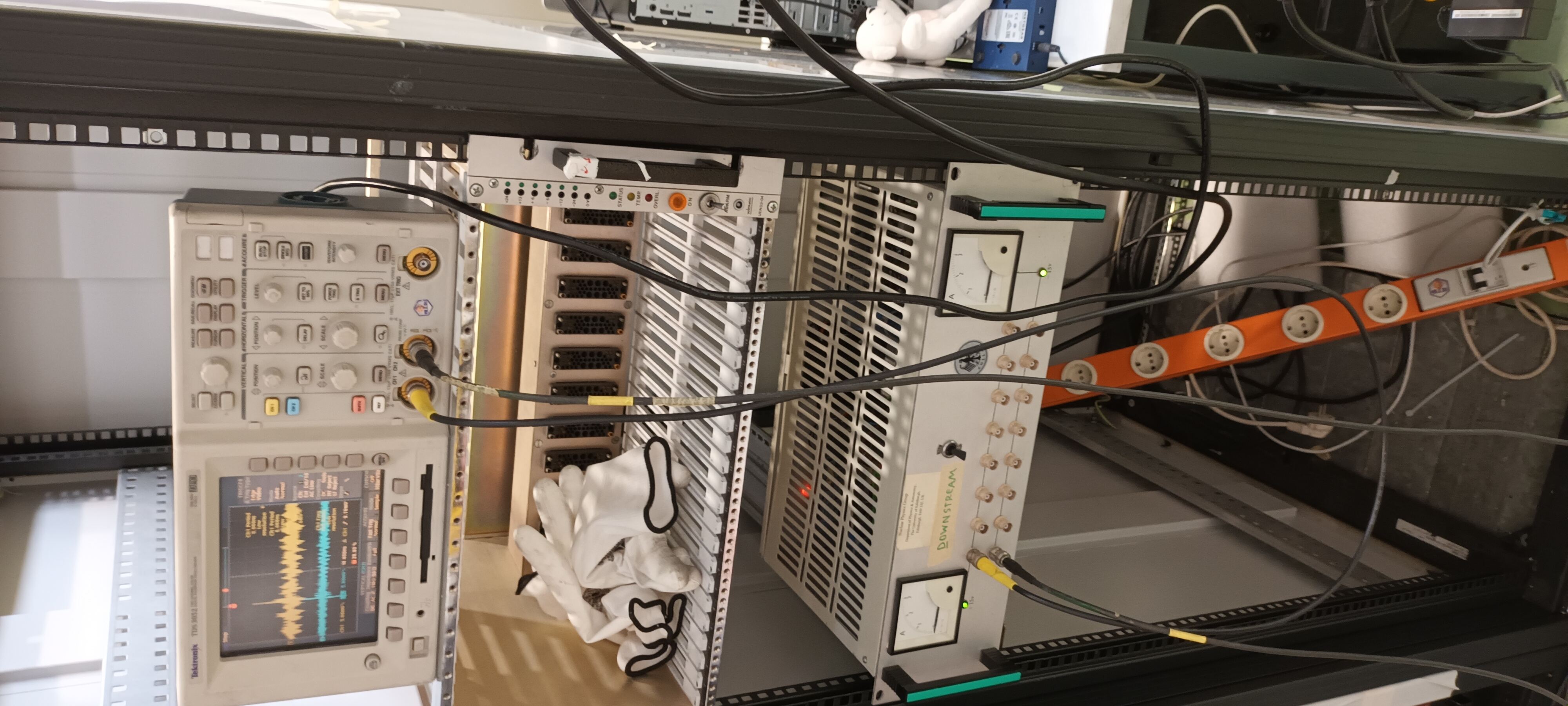
This morning 2x RAL108 +/-15V PSUs were borrowed from the Edinburgh equipment in the ISOLDE hall to check whether the same transient noise is observed at the +/-15V PSU
outputs - this was confirmed. See https://elog.ph.ed.ac.uk/nToF/63

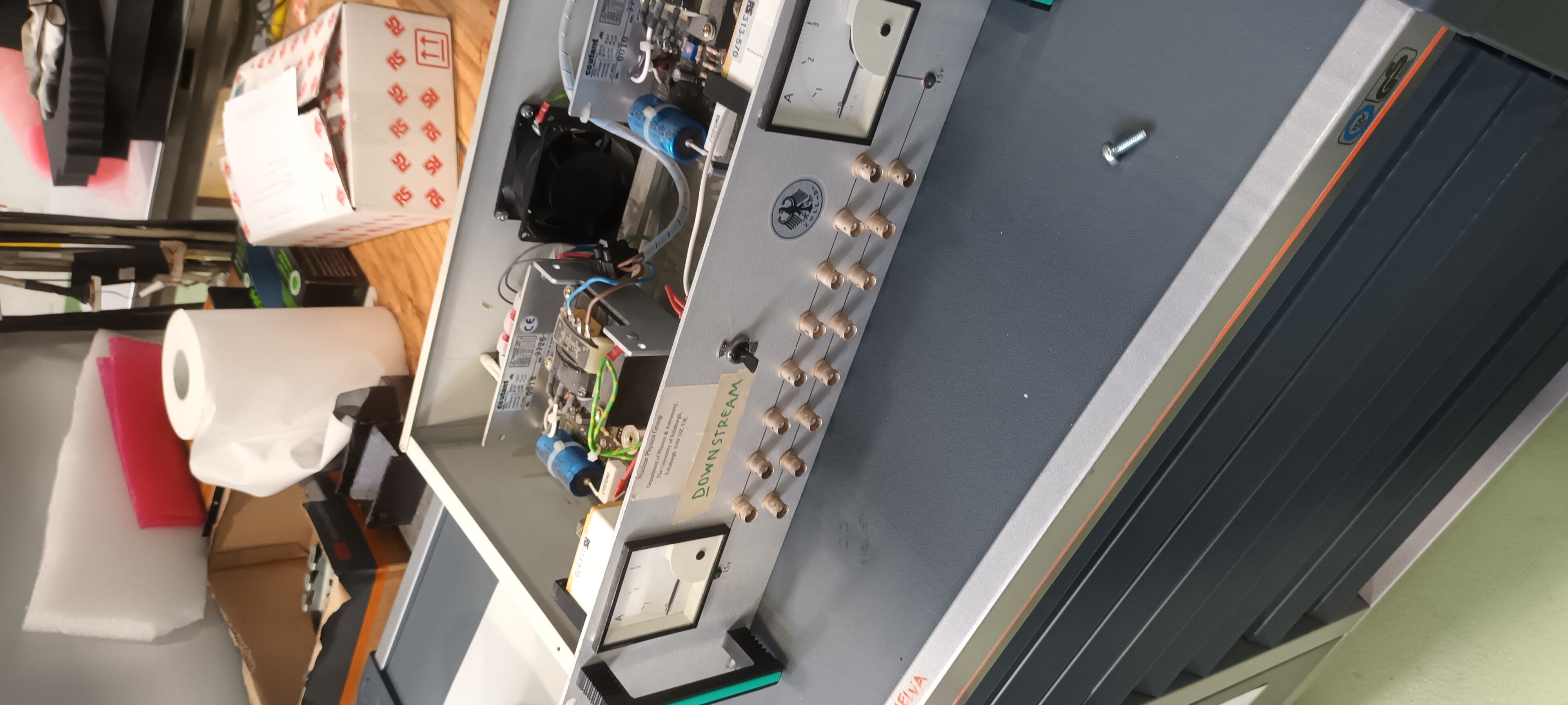
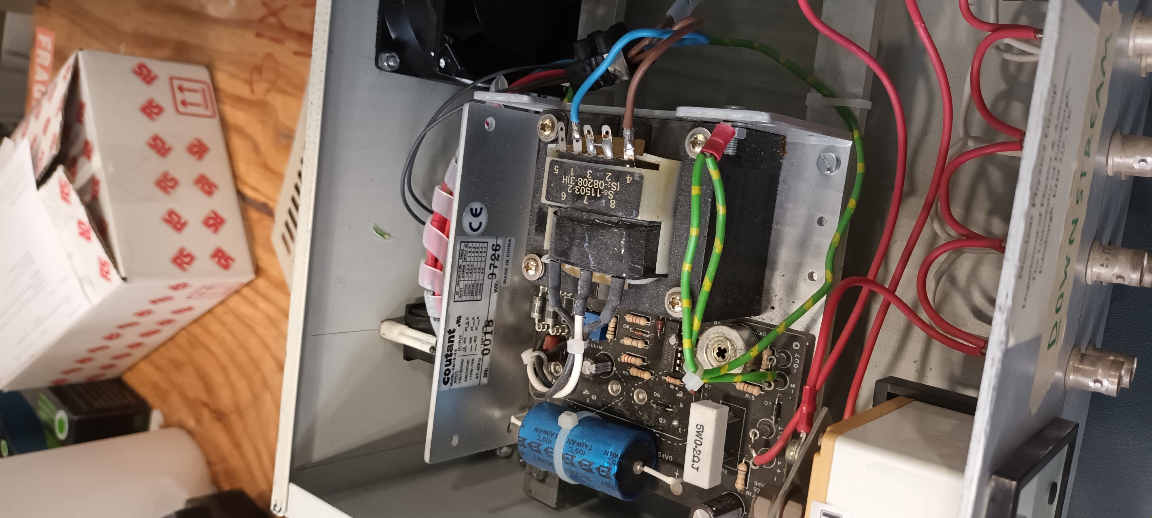
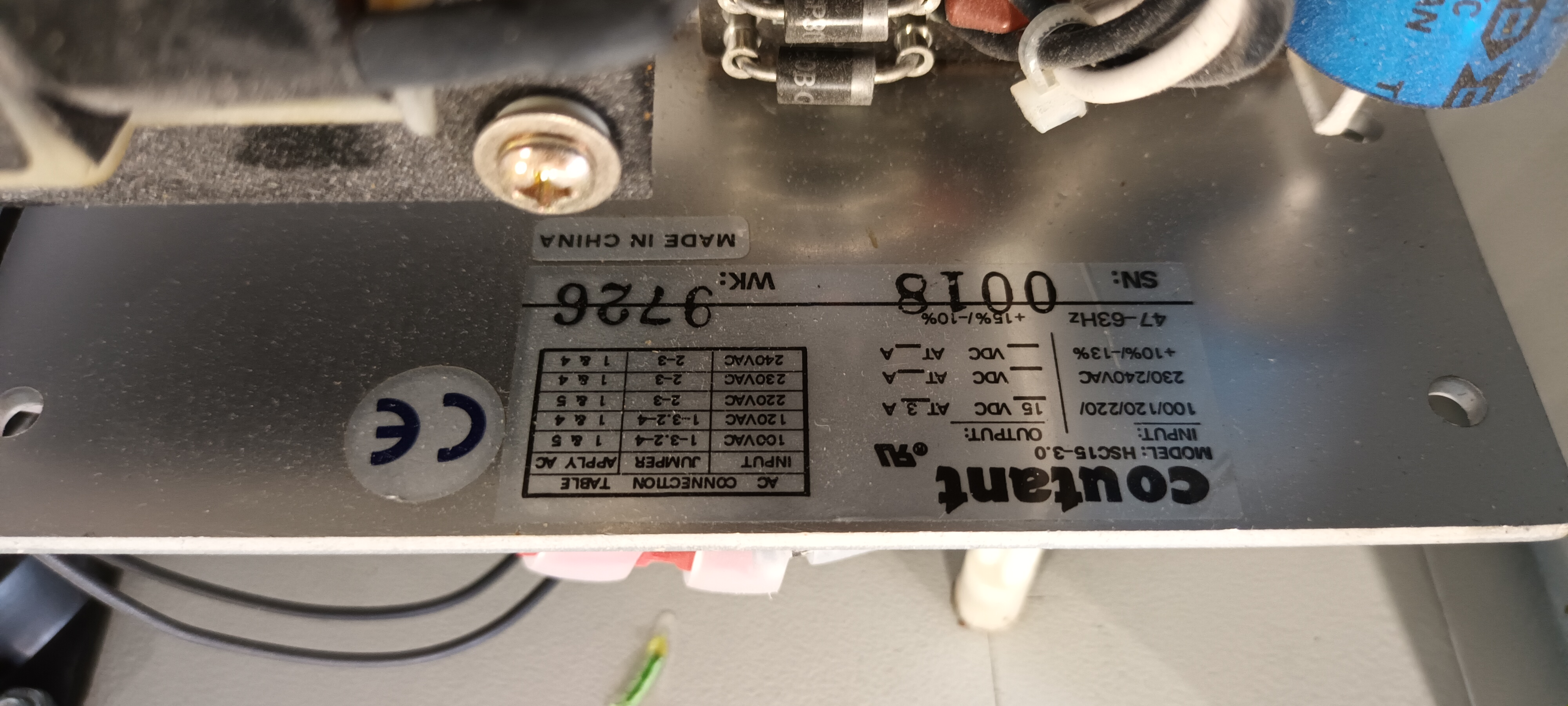
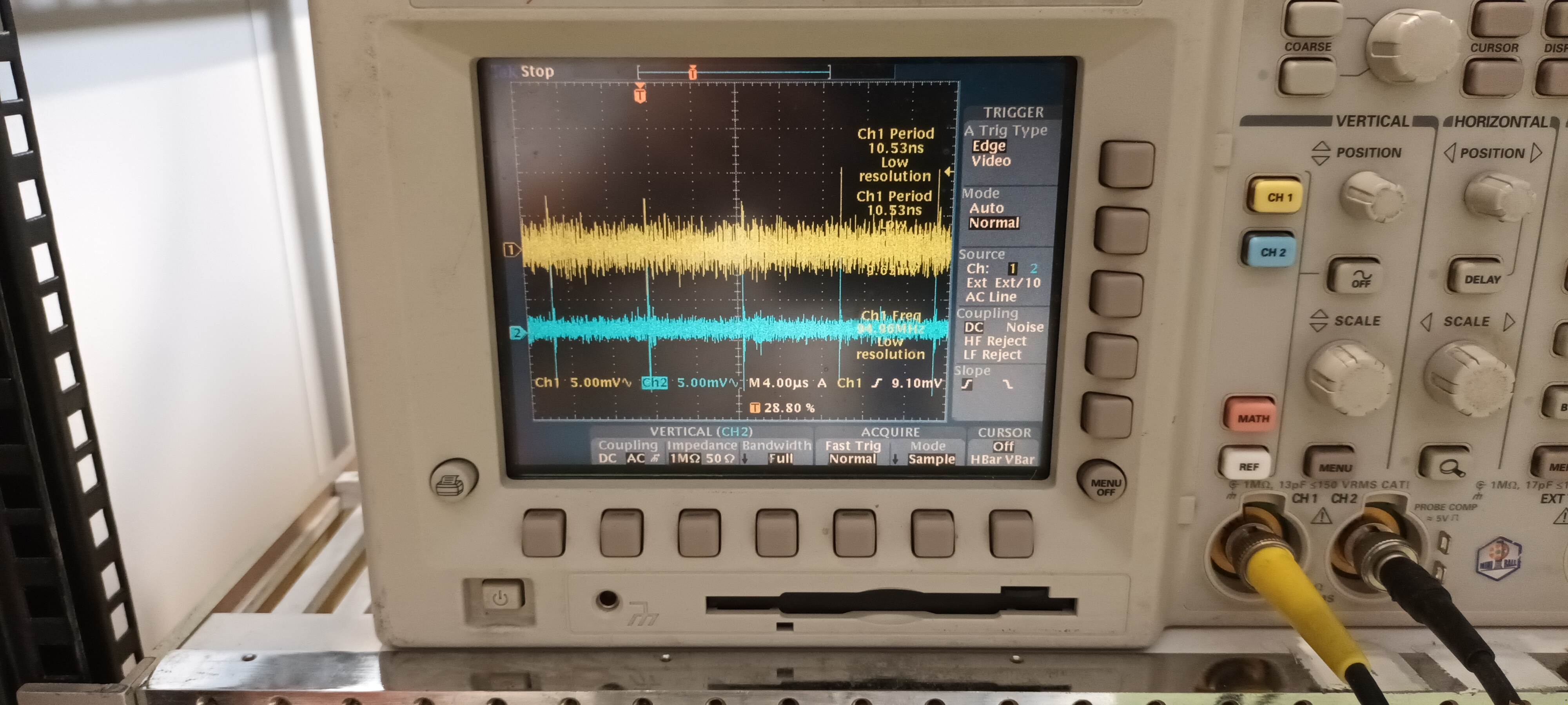
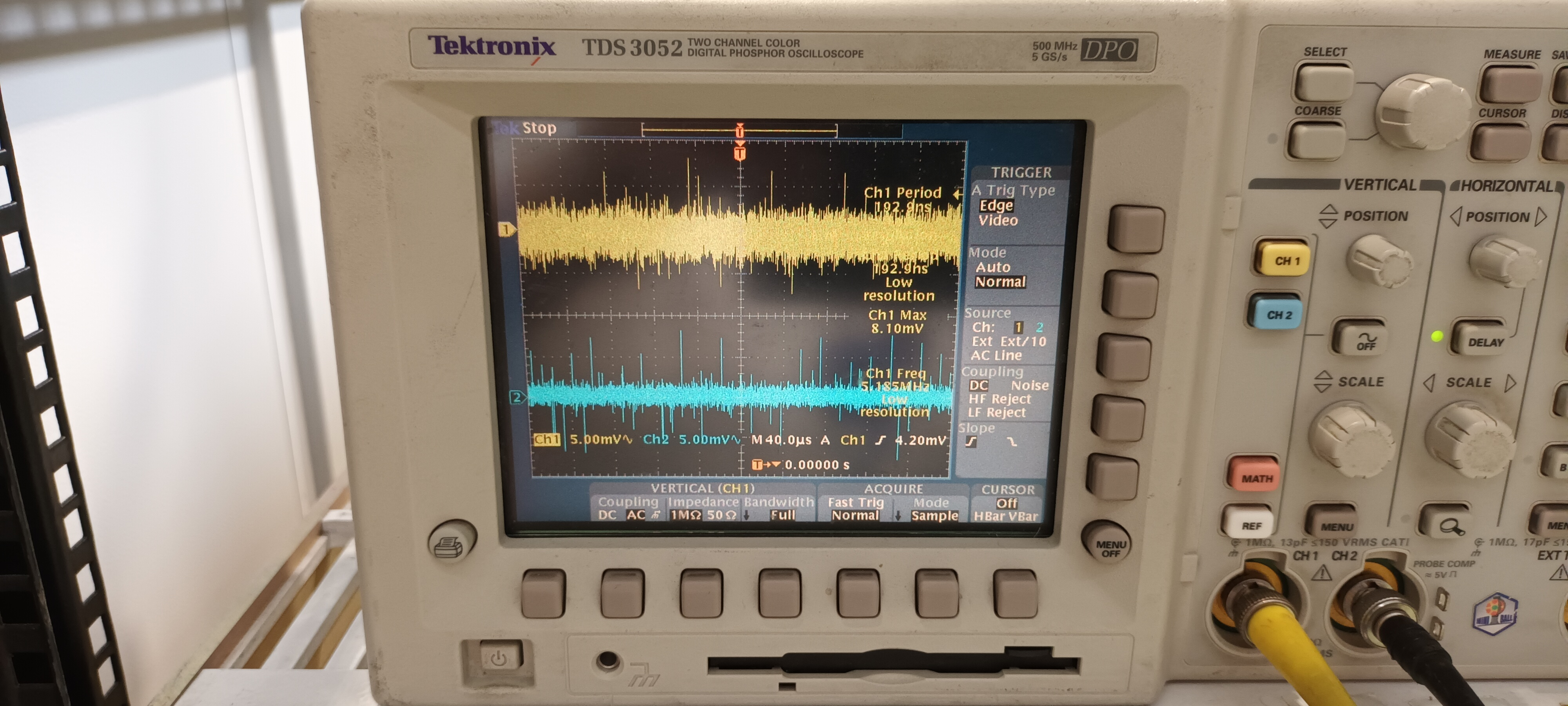
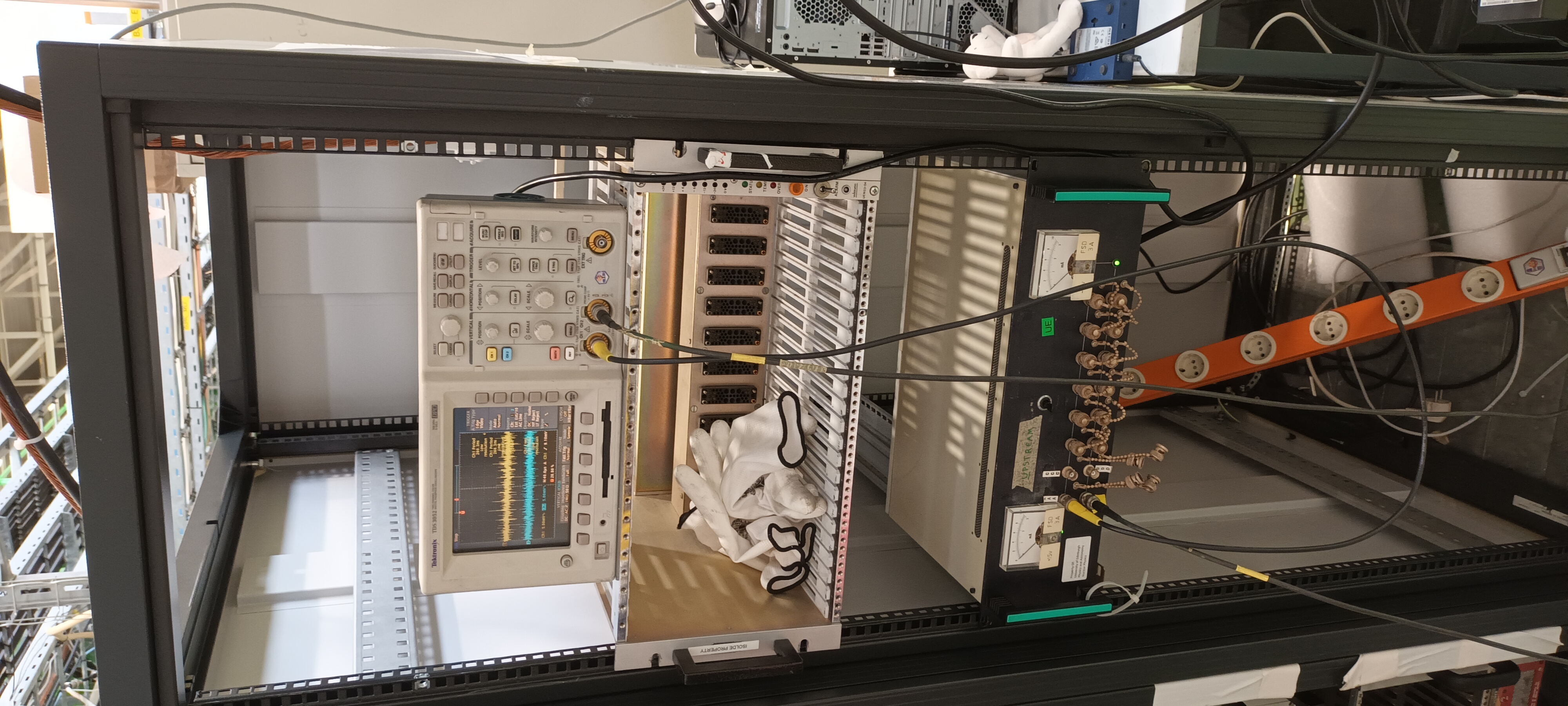
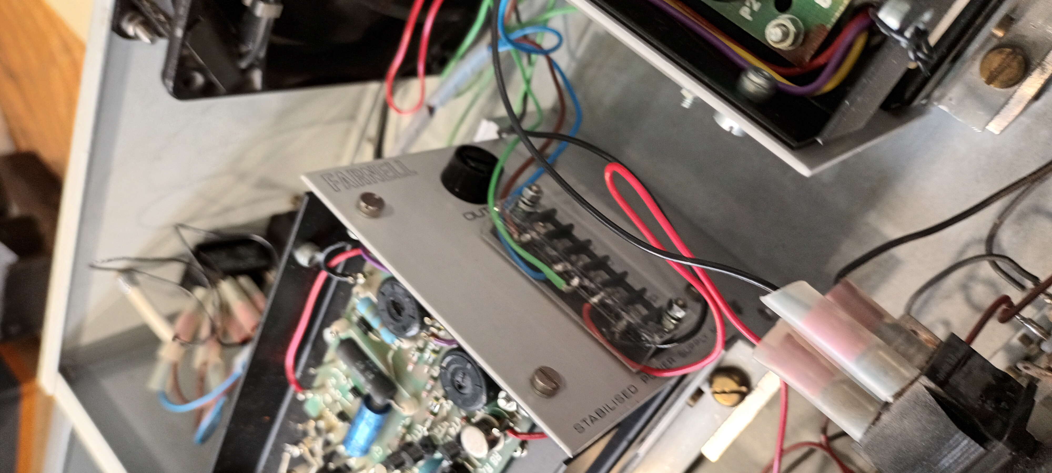
Following this test the same 2x RAL108 +/-15V PSUs were tested in the ISOLDE hall ( 19" rack adjacent to the HIE-ISOLDE GP scattering chamber ).


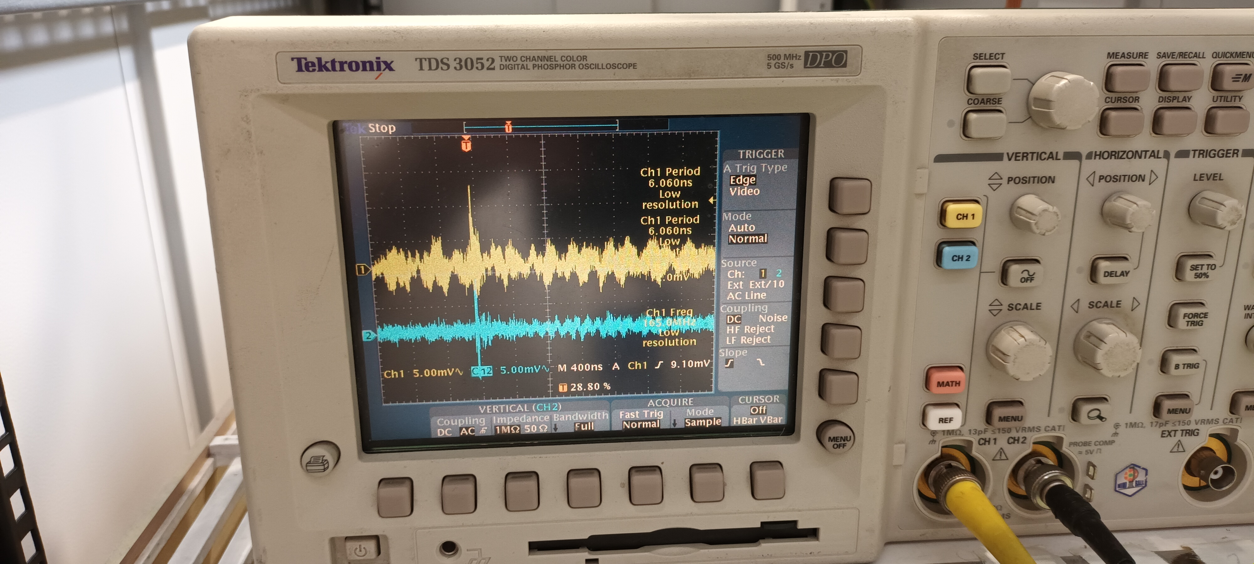
PSU #1 Coutant HSC15-3.0

Setup and PSU details - attachments 1-4

DSO ch#1 +15V AC/1M, ch#2 -15V AC/1M - y: 5mV/div x: 400ns, 4us & 40us/div - attachments 5-7


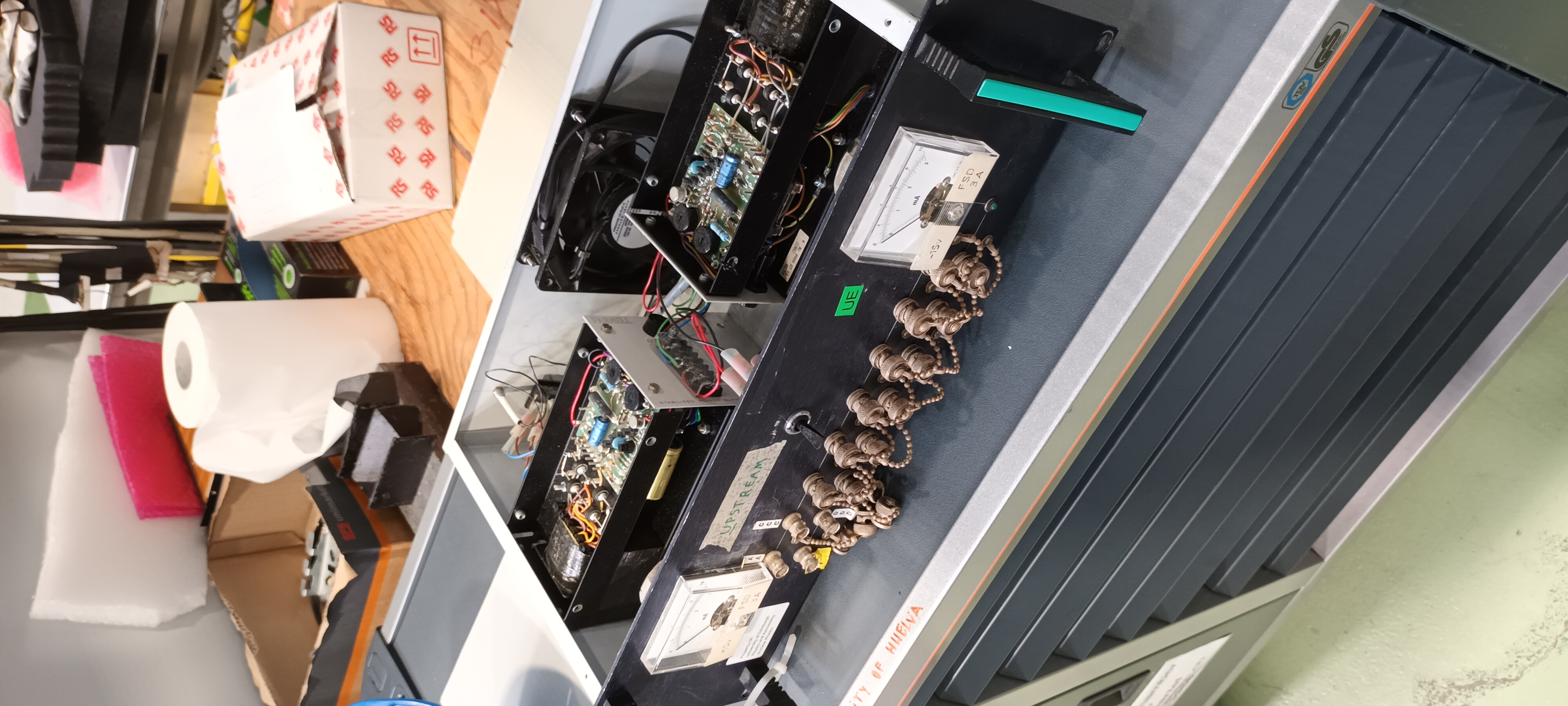
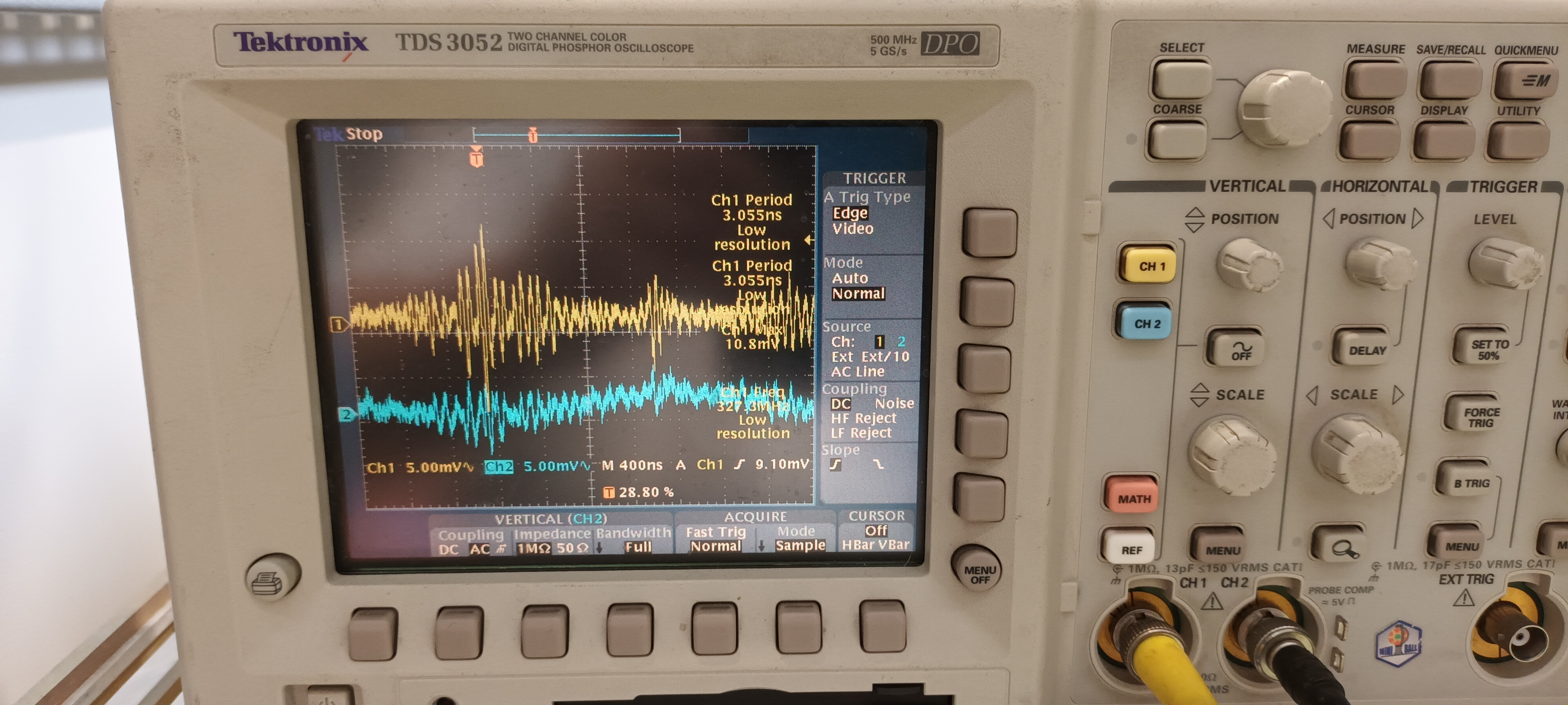
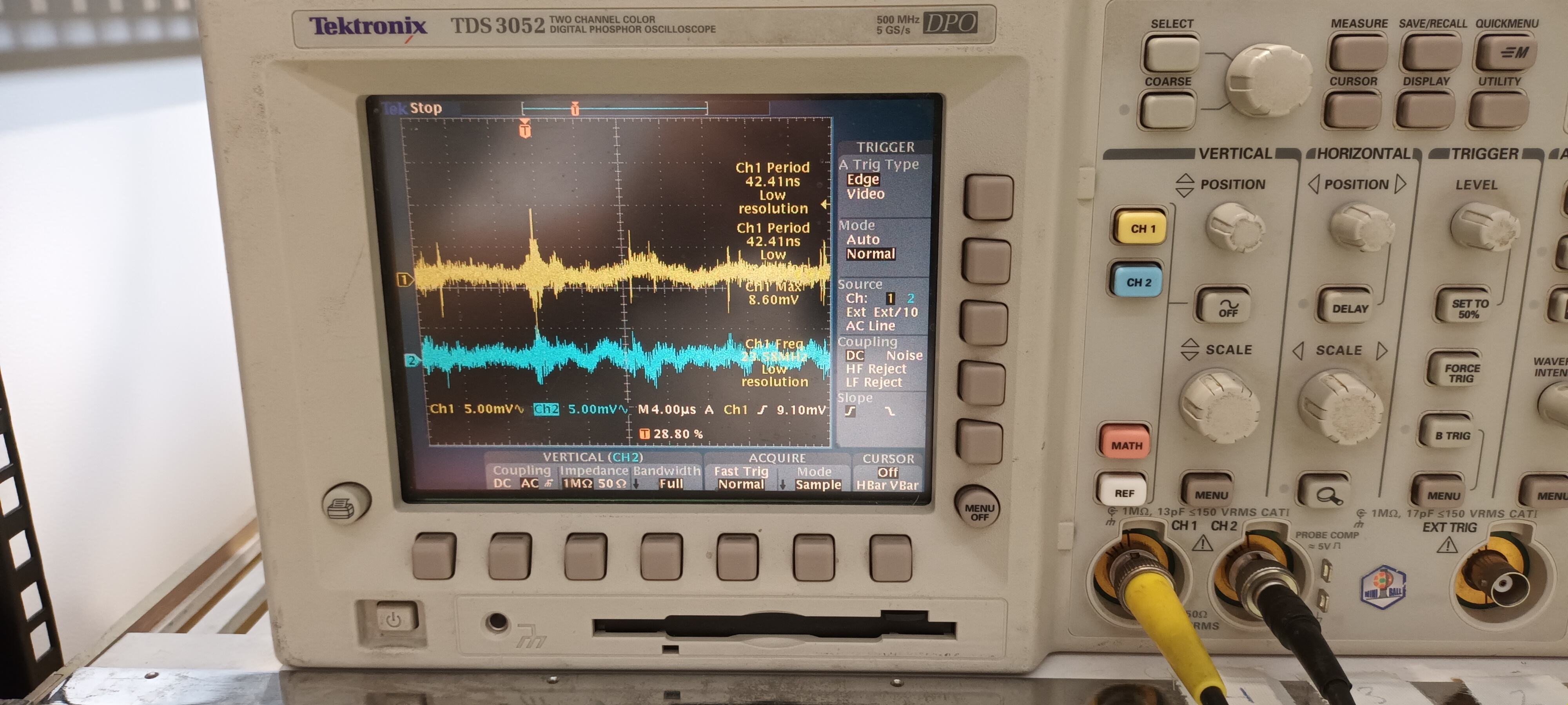
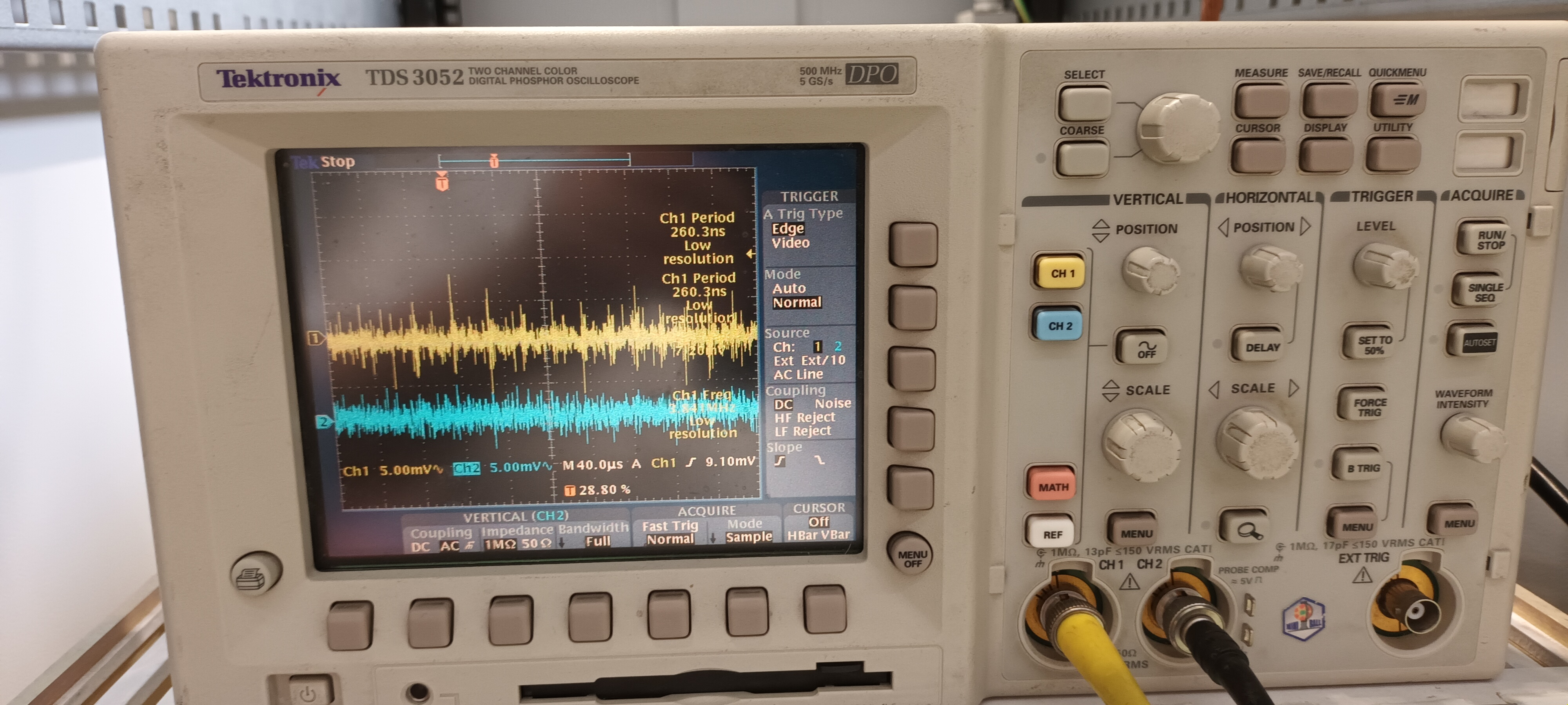
PSU #2 Farnell MX2

Setup and PSU details - attachments 8-10

DSO ch#1 +15V AC/1M, ch#2 -15V AC/1M - y: 5mV/div x: 400ns, 4us & 40us/div - attachments 11-13


Conclusion

The noise of the 2x RAL108 +/-15V PSUs differed somewhat ( frequency and structure of HF transients ) from each other in the ISOLDE test.

Compared to the EAR2, n_TOF test the amplitudes were c. 10x smaller and the HF transient frequency and structure differed.

This appears to confirm that the primary problem is the ac mains power in EAR2, n_TOF - input and/or output filtering is required. |
| Attachment 1: 20230814_110402.jpg
|
|
| Attachment 2: 20230814_111029.jpg
|
|
| Attachment 3: 20230814_111128.jpg
|
|
| Attachment 4: 20230814_111216.jpg
|
|
| Attachment 5: 20230814_110410.jpg
|
|
| Attachment 6: 20230814_110424.jpg
|
|
| Attachment 7: 20230814_110516.jpg
|
|
| Attachment 8: 20230814_110053.jpg
|
|
| Attachment 9: 20230814_110723.jpg
|
|
| Attachment 10: 20230814_110738.jpg
|
|
| Attachment 11: 20230814_110158.jpg
|
|
| Attachment 12: 20230814_110142.jpg
|
|
| Attachment 13: 20230814_110105.jpg
|
|
|
26
|
Fri Sep 2 12:03:40 2016 |
Sarah | SPD card changed |
14 bit card replaced for DEED 9-12, to prevent issue with pulser arriving before gamma flash. |
|
58
|
Fri Aug 11 13:06:54 2023 |
Annie | Signal Spreadsheet info |
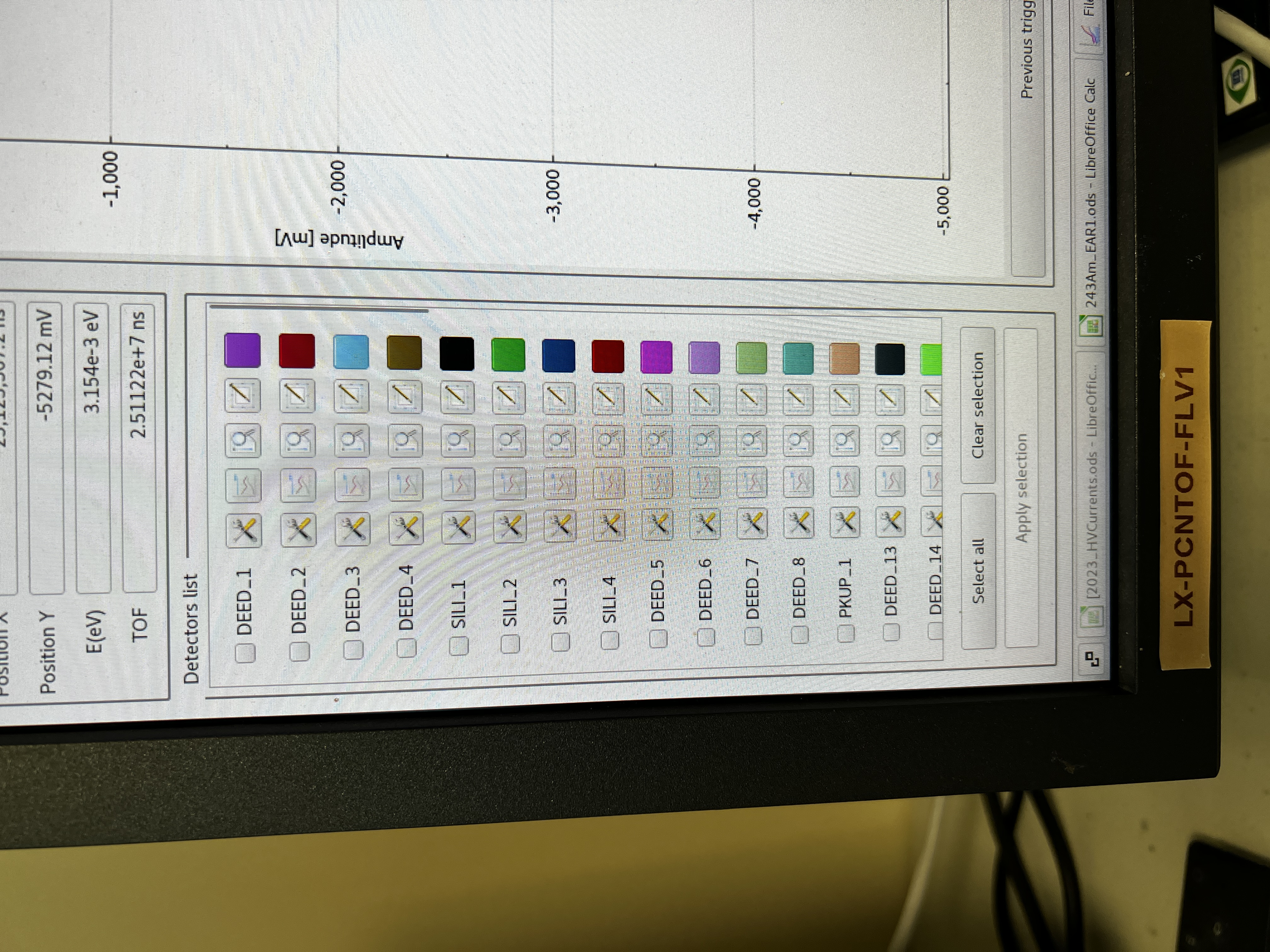
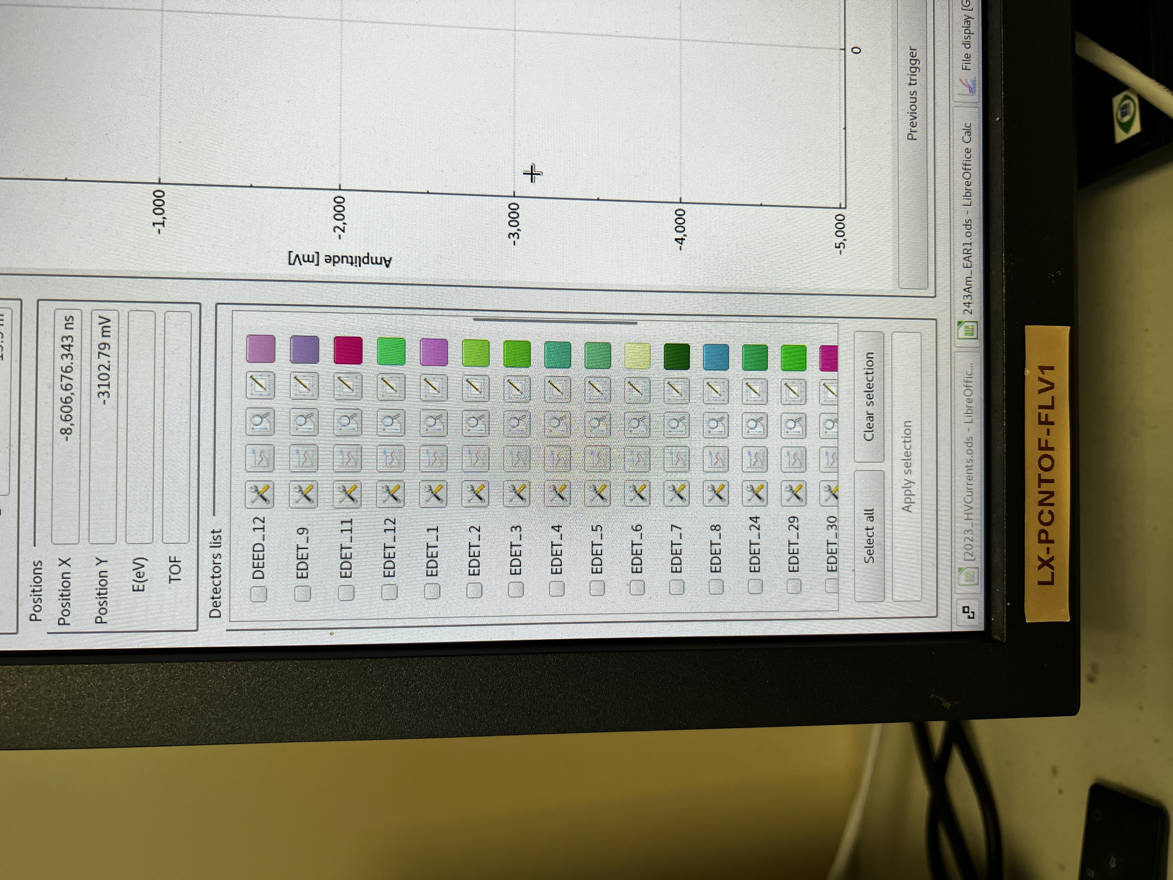
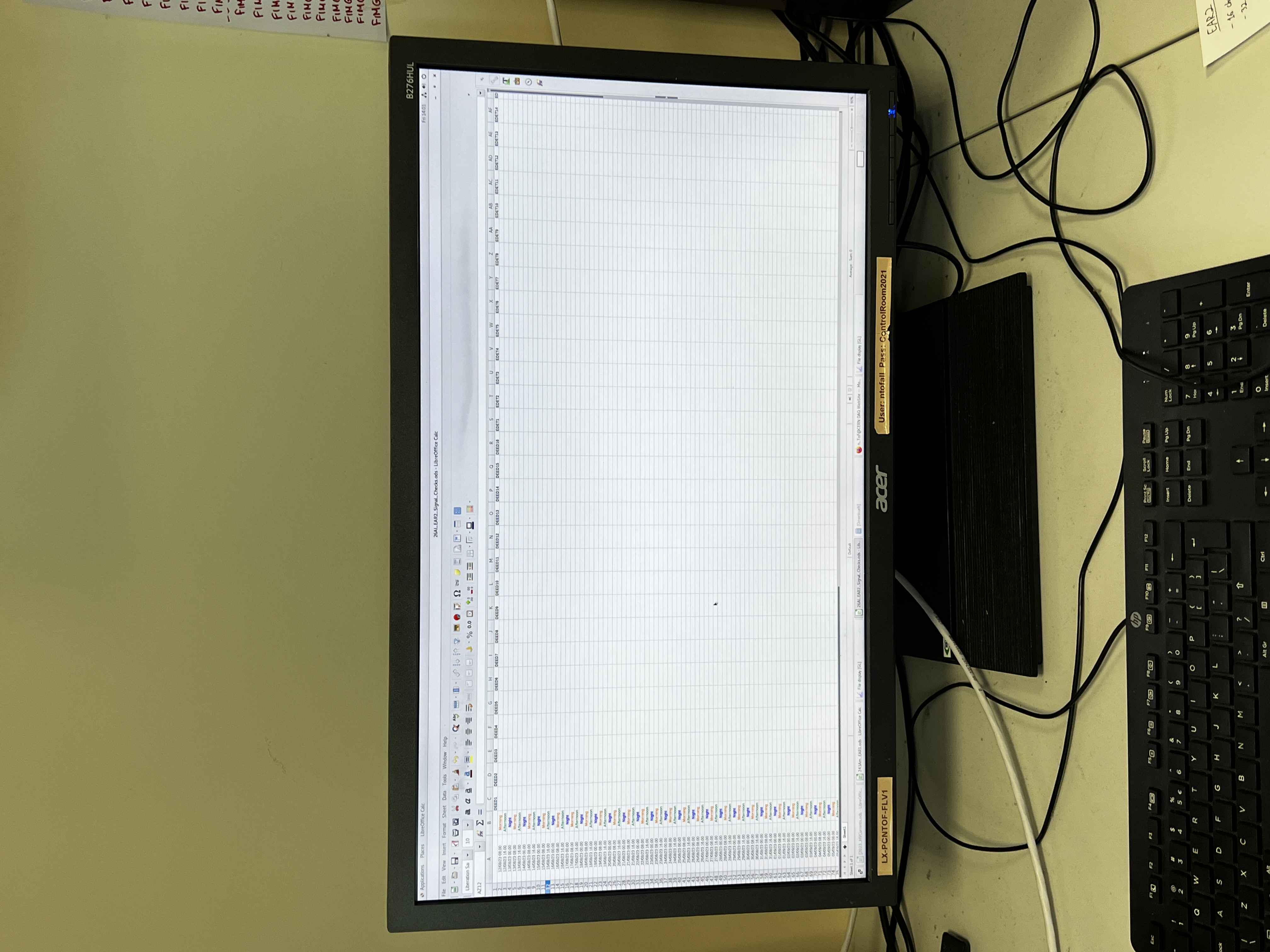
Spreadhseet made for shifters to manually enter that they have checked each signal and that they can see gamma-flashes. It is saved as "26Al_EAR2_Signal_Checks.ods", it is located on the second monitor on the right of the control room, next to the monitor used to see the beam intensity (same monitor used to see signals).
It will stay open throughout the campeign. Shifters have been told to check signals more than just the once to record that they're okay, and there is a comments box for shifters to add any comments/issues that arises after they have recorde that they have checked the signals at least once. |
| Attachment 1: IMG_2920.JPG
|
|
| Attachment 2: IMG_2921.JPG
|
|
| Attachment 3: IMG_2922.JPG
|
|
|
36
|
Sat Oct 8 11:56:49 2022 |
Nikolay Sosnin | Silicon Strips of Concern |
DEED 6 and 9 no signal throughout the campaign.
EFED 27 high oscillations in baseline throughout the campaign. |
|
51
|
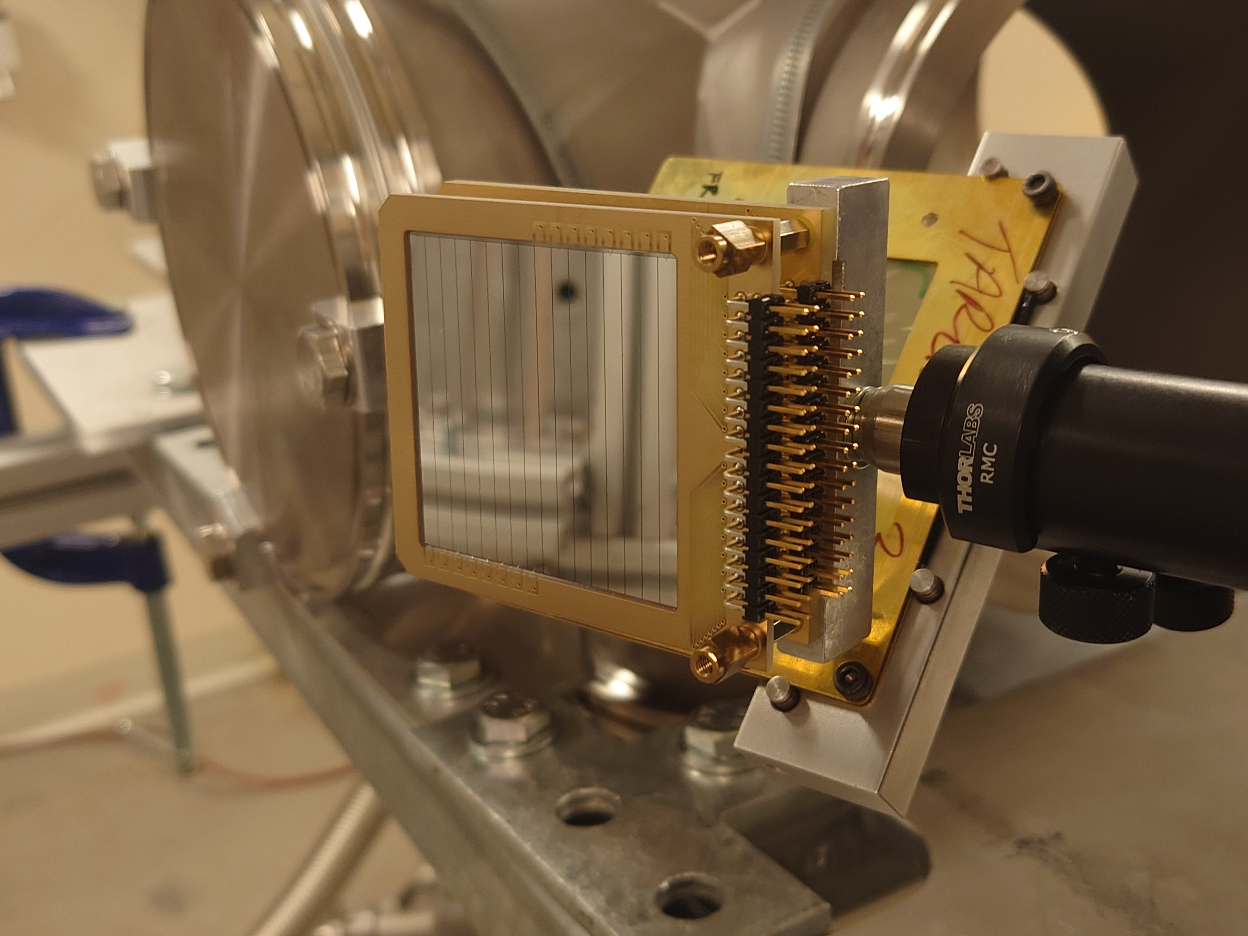
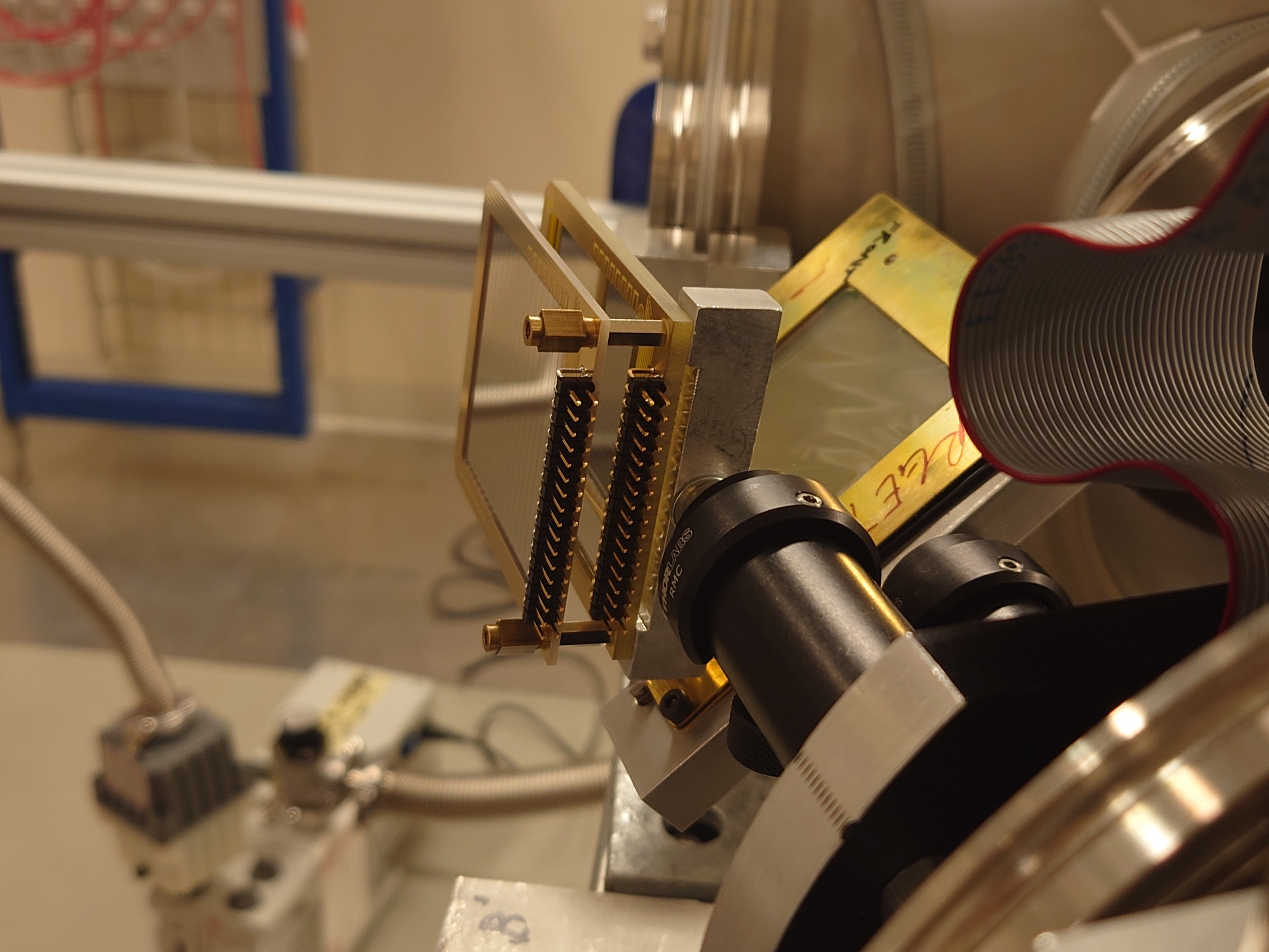
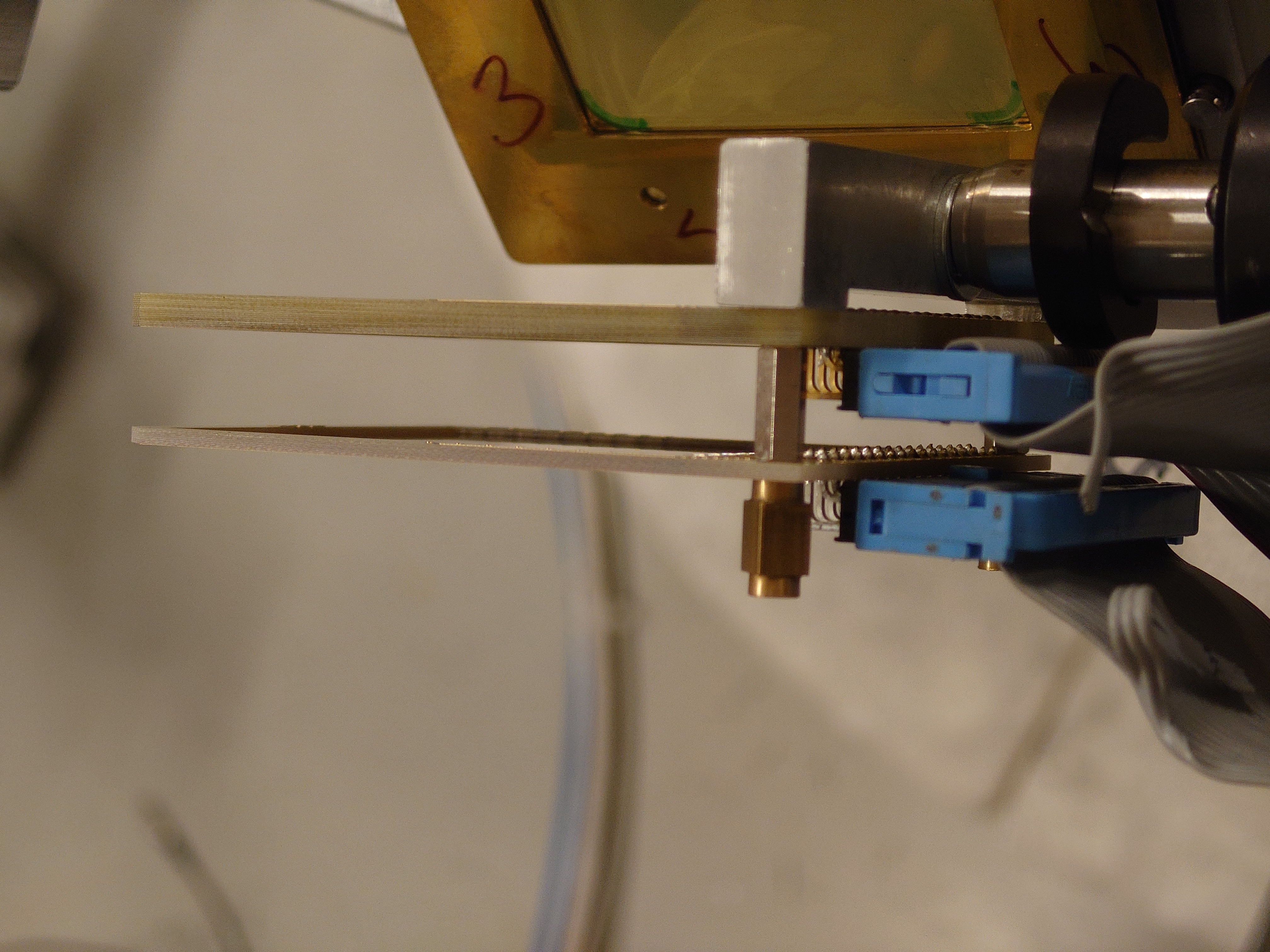
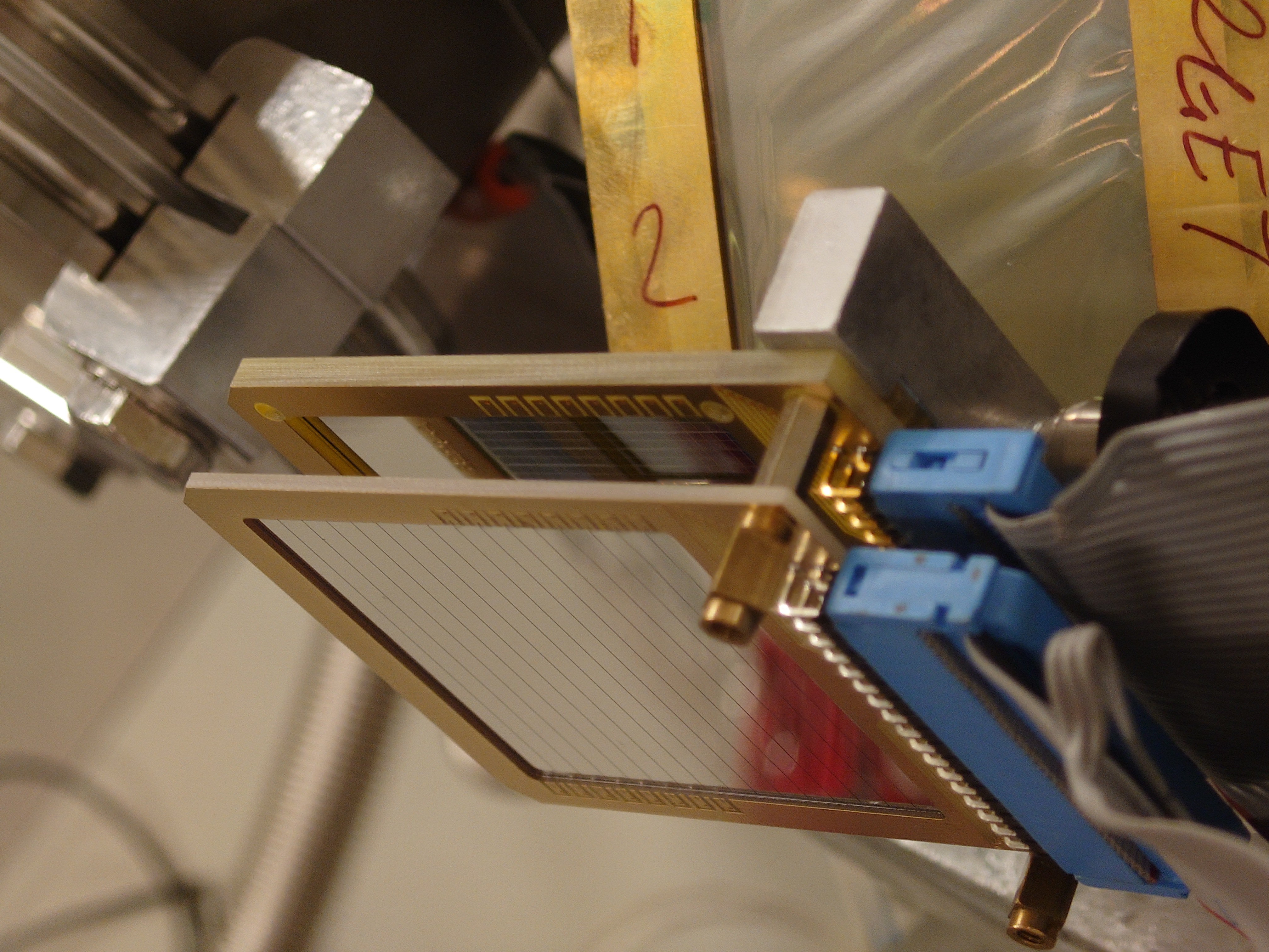
Thu Aug 10 11:30:32 2023 |
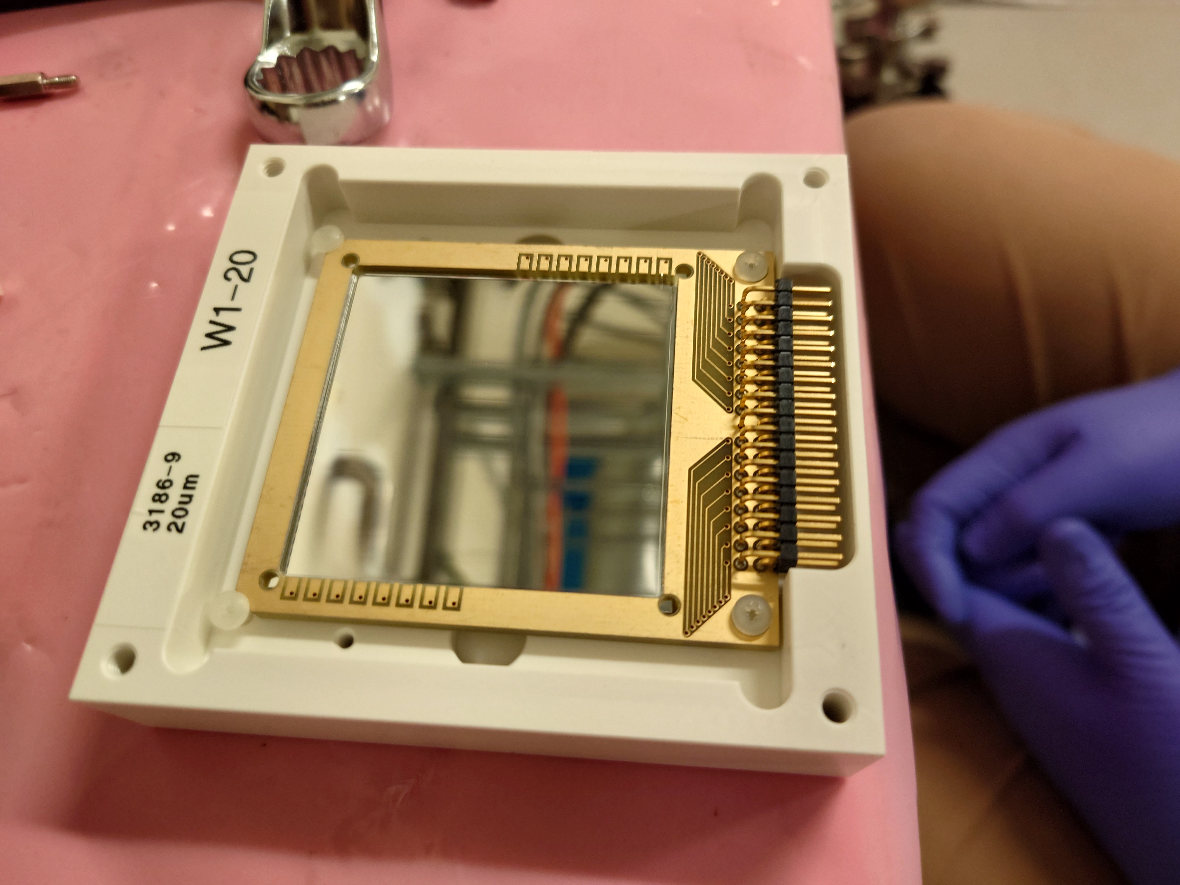
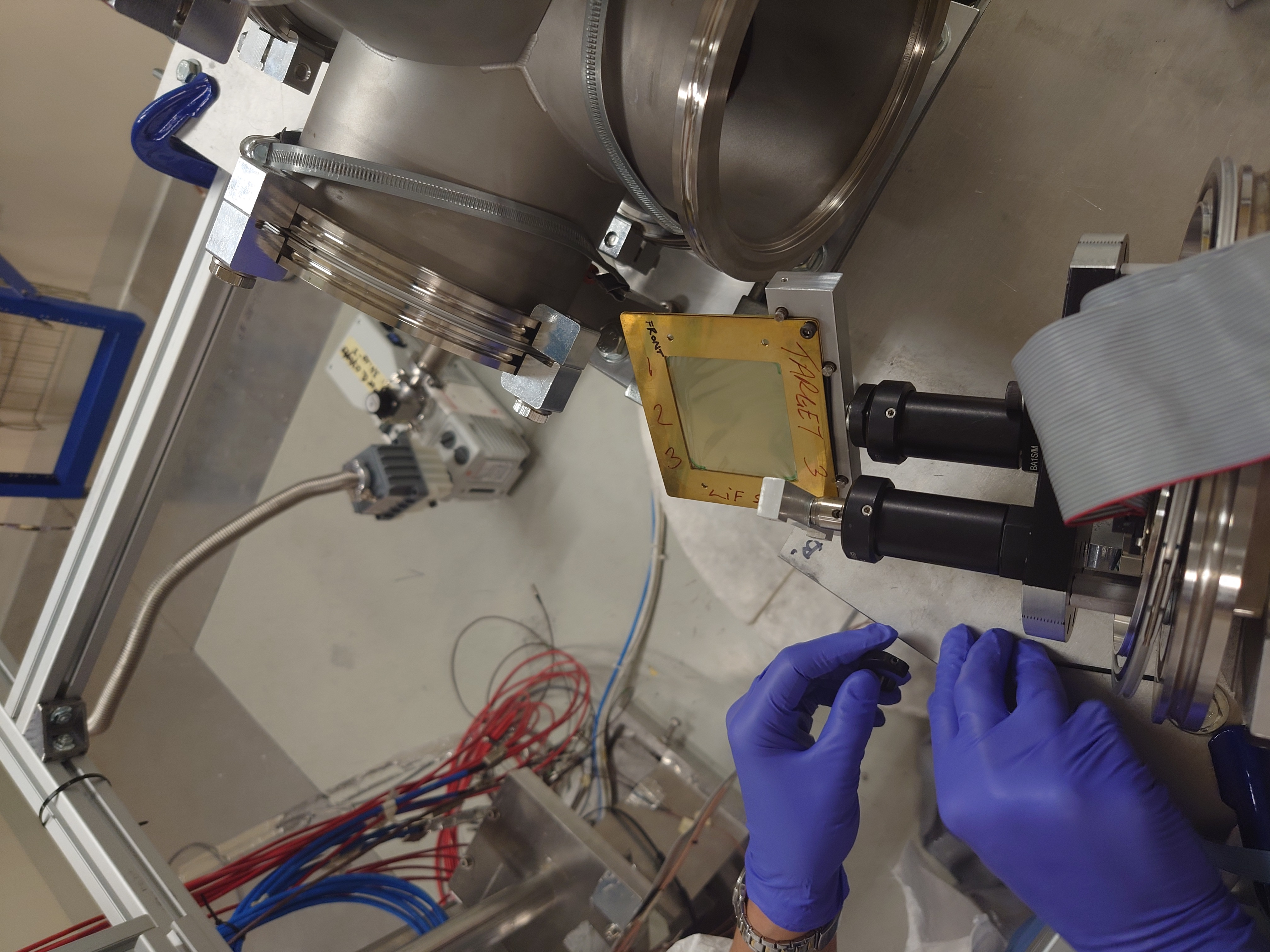
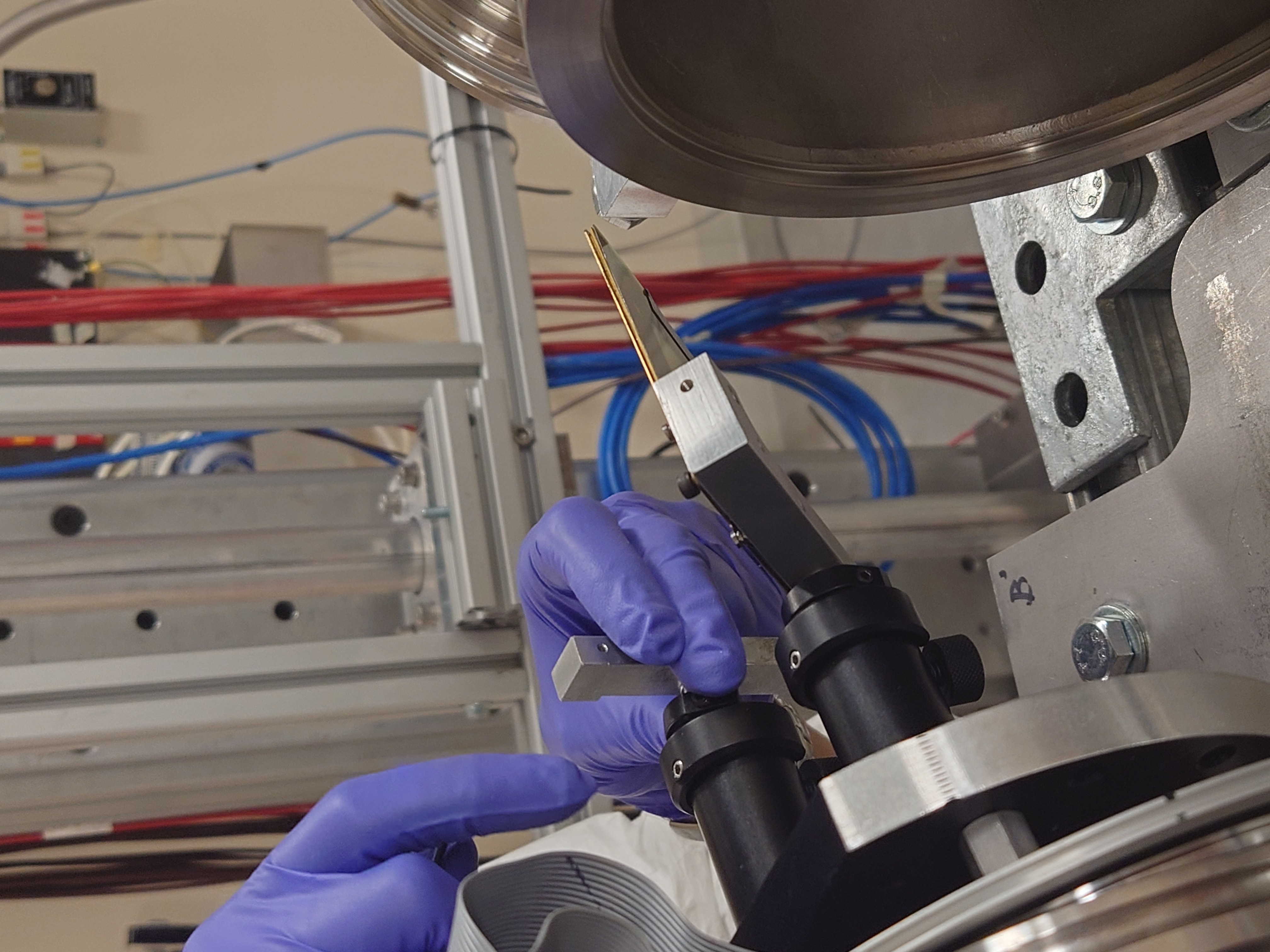
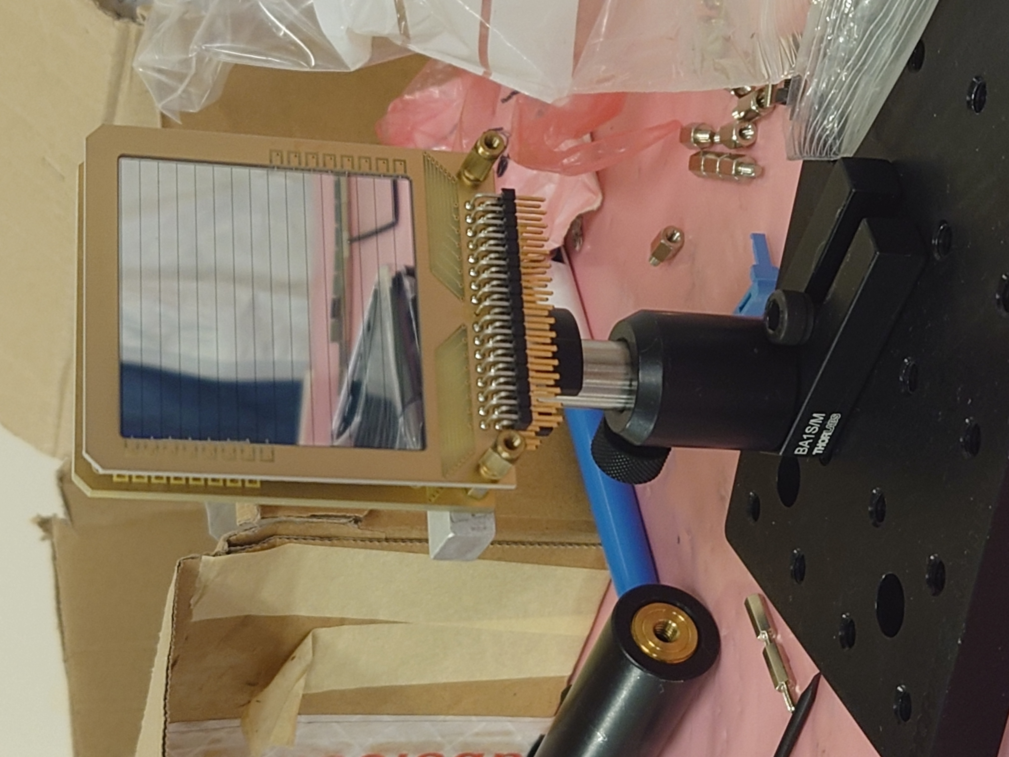
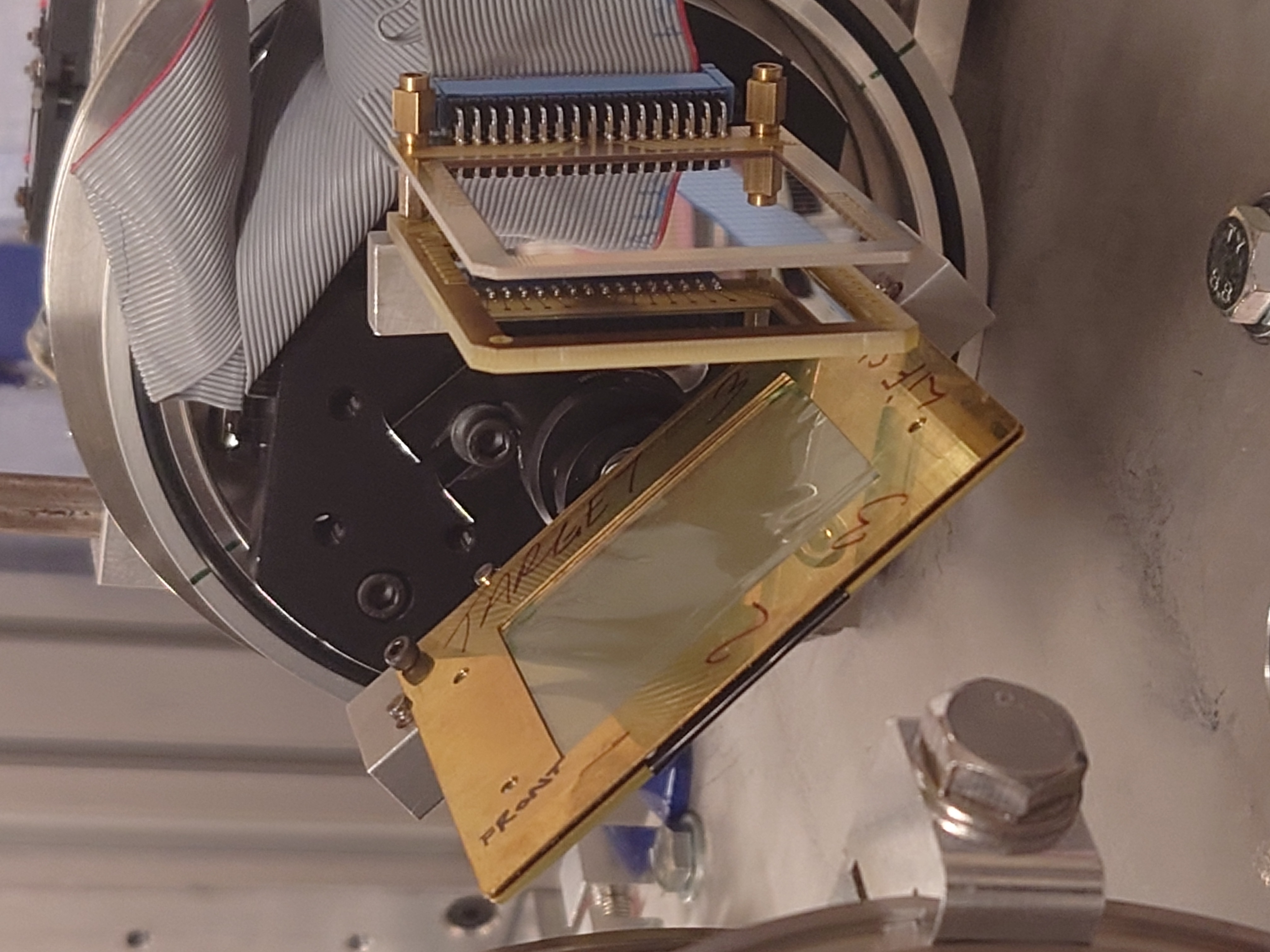
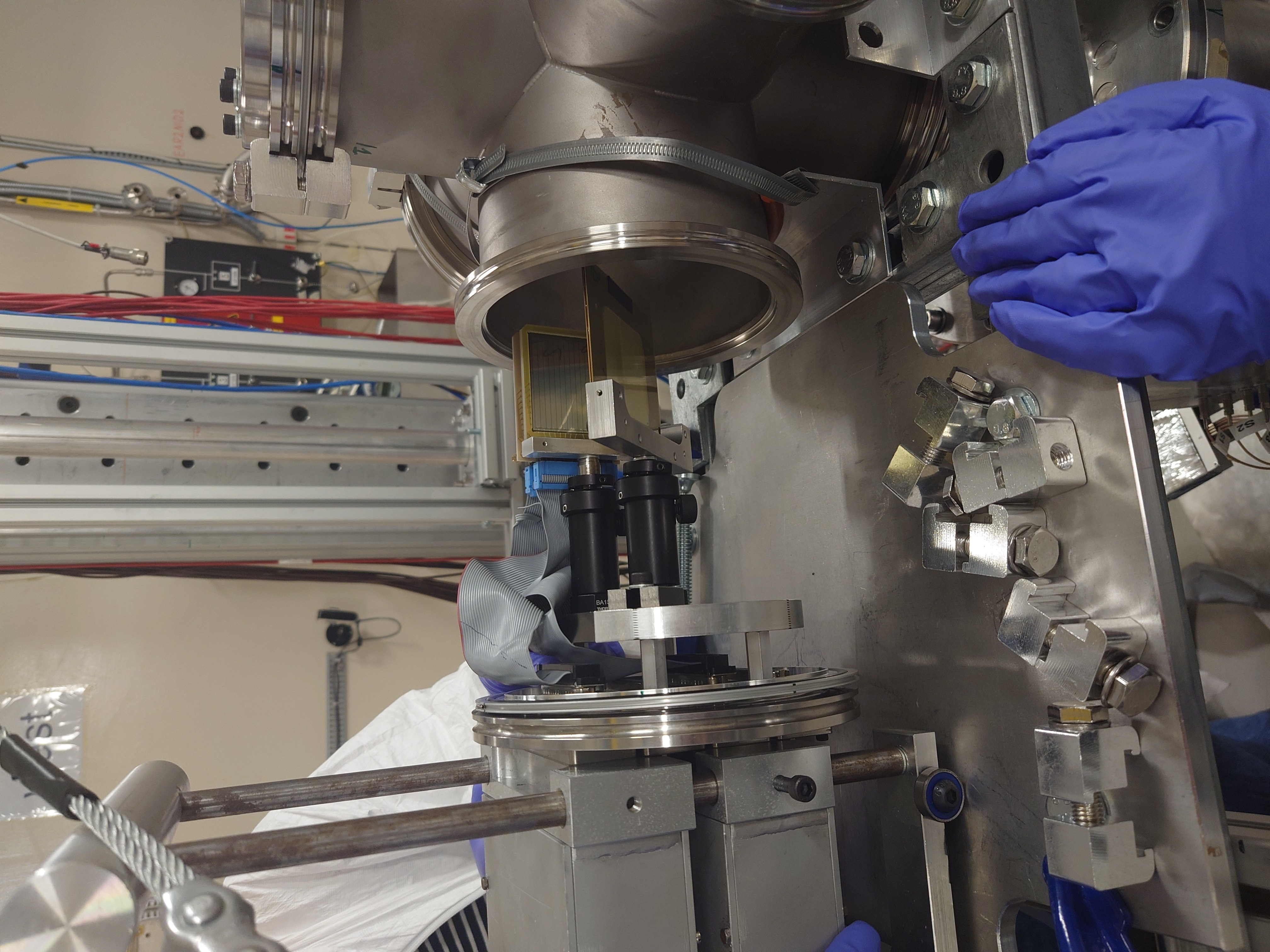
Nikolay Sosnin | Silicons and LiF3+Gafchromic Target |
|
| Attachment 1: EDET_150um_Box.JPG
|

|
| Attachment 2: EDET_150um.JPG
|

|
| Attachment 3: EDET_ID.JPG
|
|
| Attachment 4: DEED_20um_Box.JPG
|
|
| Attachment 5: LiF3_Gafchrmoic_Target_Mounted.JPG
|
|
| Attachment 6: LiF3_Gafchromic_Side.JPG
|
|
| Attachment 7: LiF3_Gafchromic_Front.JPG
|

|
| Attachment 8: Detector_Mount_and_LiF3.JPG
|

|
| Attachment 9: Detectors_Mounting.JPG
|

|
| Attachment 10: Detectors_Mounted_DEED.JPG
|

|
| Attachment 11: Detectors_Mounted_EDET.JPG
|
|
| Attachment 12: Detectors_and_LiF3_Gafchrmoic_TestPosition.JPG
|

|
| Attachment 13: Detectors_and_LiF3_Gafchrmoic_TestPosition_Back.JPG
|
|
| Attachment 14: Detectors_and_LiF3_Gafchrmoic_TestPosition_Below.JPG
|
|
| Attachment 15: Detectors_and_LiF3_Gafchrmoic_TestPosition_Above.JPG
|
|
| Attachment 16: Detectors_and_LiF3_Gafchrmoic_TestPosition_Tilt.JPG
|
|
| Attachment 17: Detectors_and_LiF3_Gafchrmoic_TestPosition_Front.JPG
|
|
| Attachment 18: Assembly_Insert.JPG
|
|
|
30
|
Thu Oct 6 09:34:30 2022 |
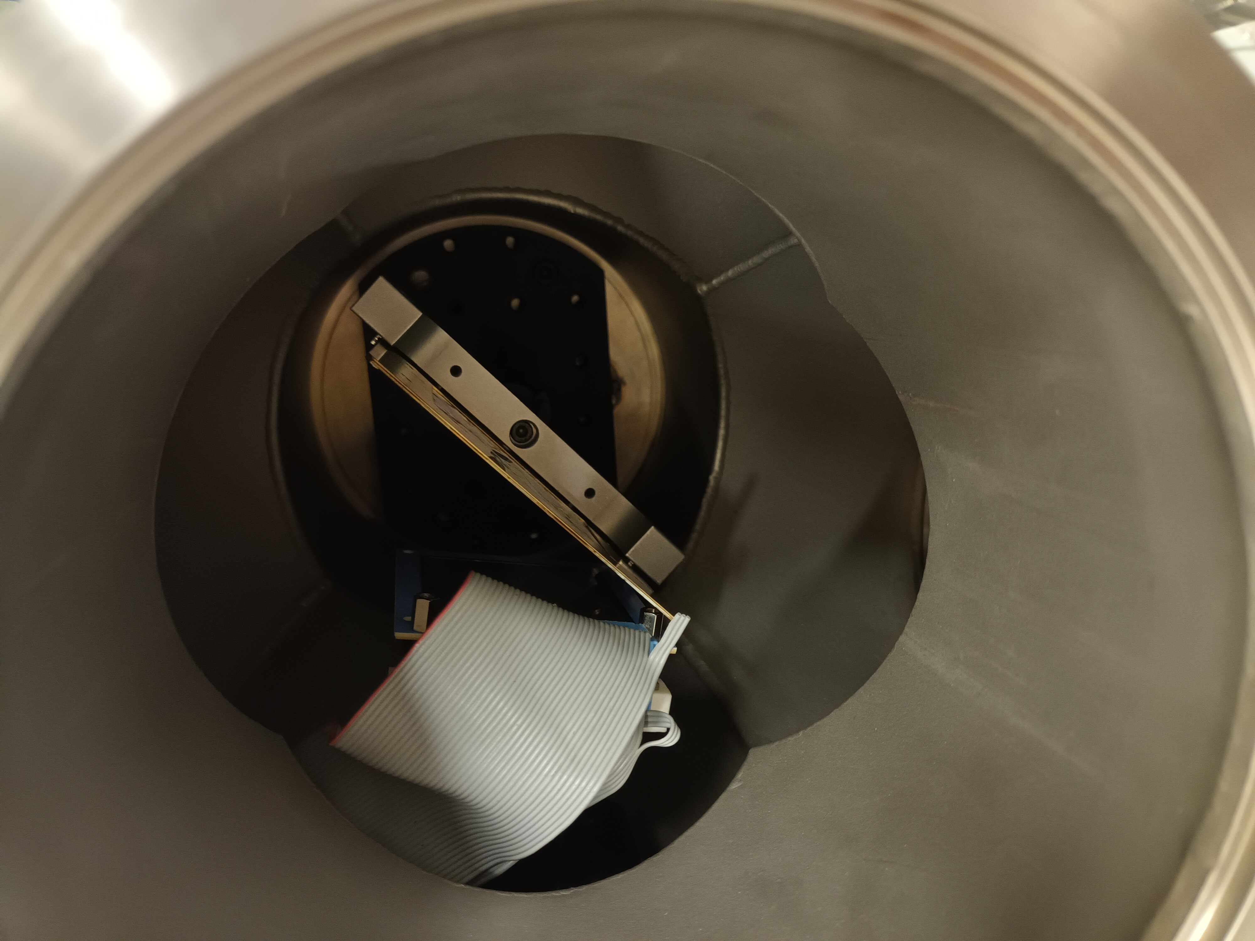
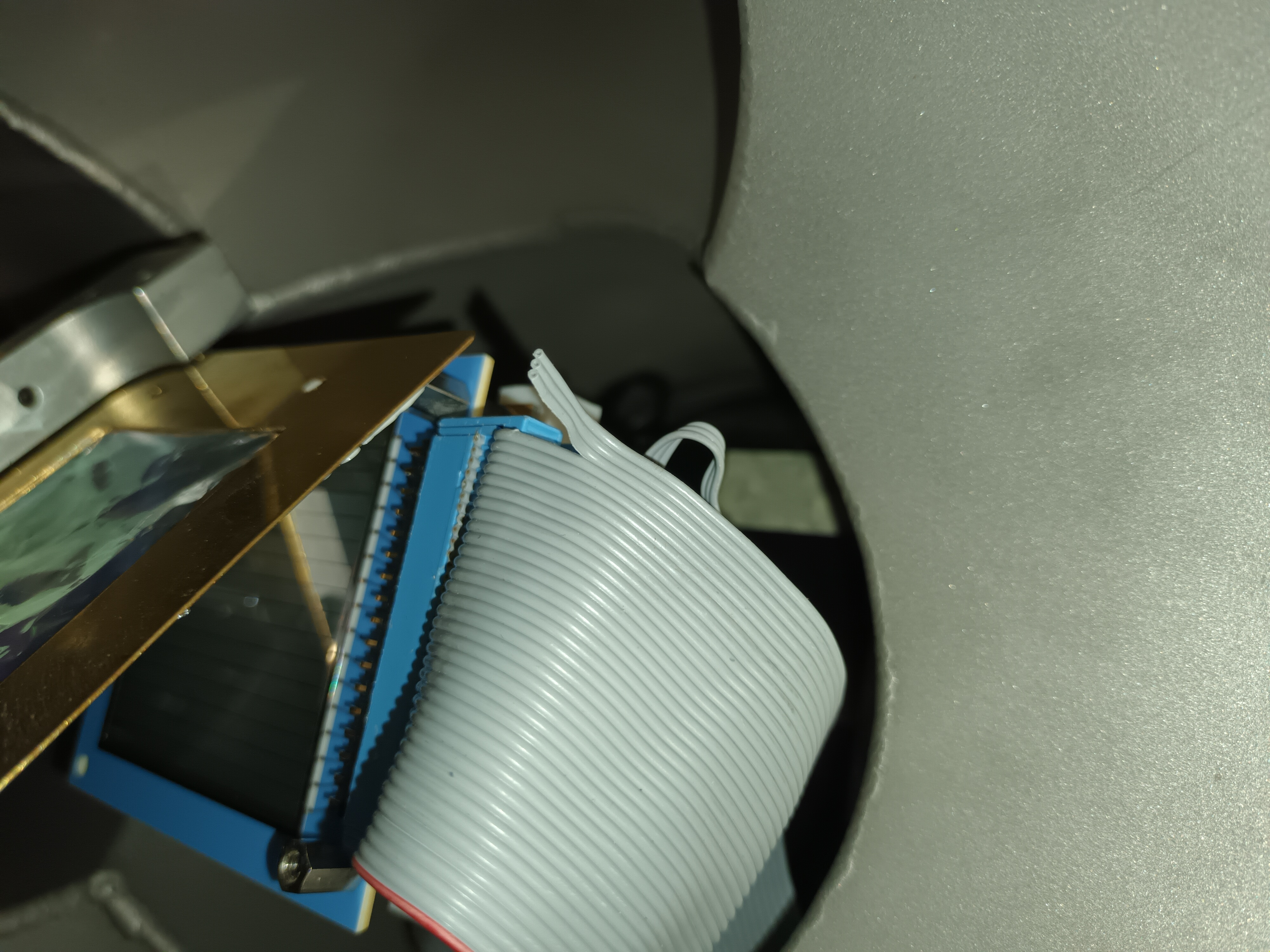
Claudia | Test setup Photos and cabling |
Setup 5.10.22
dE 20 um (ID 2837-33) and 494 um double sided (ID 1194-9)
46 channels (2 connectors missing)
LiF4 in beam
dE: Big flat cables from preamp 22 and 23 into 1A and 1B
E: from preamp 24+25 go into 2A, 2B and 3A 3B
LEMO converter box: Cable 1: dE
Cable 3: E n+n
unlabeled cable: E p+n
E detector voltage: -133 V, leakage current -0.53 micro-Amp
dE detector voltage -22 V, leakage current -0.03 micro-Amp
For the E detector one of the edge p+n strip bond-wires is suspected broken. |
| Attachment 1: 20221005_174742.jpg
|
|
| Attachment 2: 20221005_174759.jpg
|
|
| Attachment 3: 20221005_184752.jpg
|

|
| Attachment 4: 20221005_184801.jpg
|

|
| Attachment 5: 20221005_174742.jpg
|

|
|
44
|
Mon Jul 31 10:21:41 2023 |
Nikolay Sosnin | n_TOF Data and Filtering |
|
| Attachment 1: Al26_Filtering.pptx
|