| ID |
Date |
Author |
Subject |
|
52
|
Thu Aug 10 16:11:57 2023 |
TD, NS, AR | Noise |
Observe c. 2mV p to p noise with DSO ( Z_in = 50 Ohm ) c. 60us period with HF structure. DSO connected to junction box via 34-way IDC - 16x Lemo-00 adaptor.

Origin of noise upstream of 4x34-way to 8x16-way Junction Box. Not microphonics from Edwards RV5 Rotary Pump.
No change observed with simple ground connections between NIM bin/+/-15V PSU/Junction Box and MSL type W1 preamplifier units/vacuum chamber/support assembly.


Estimate of electronic noise

Pulser BNC PB-5

Amplitude 0.5V
Attenuation x1
Decay time 1ms
Frequency 50Hz

Preamplifier RAL108
Output impedance 100 Ohm
Sensitivity 20mV/MeV ( into high Z load ), 6.7mV/MeV ( into 50 Ohm load )

Amplifier EG&G Ortec 571
Input terminated by 50 Ohm
Gain x1 (internal) x 1.0 (fine gain) x 50 (coarse gain ) = 50
Shaping time 0.5us

MCA Amptek 8000D
Input FSR 10V
12 bit ADC


Nominal gain = 6.7mV/MeV x 50 = 335mV/MeV

12 bit ADC input FSR = 10V / 0.335V/MeV = 29.85MeV FSR or 7.3keV/channel


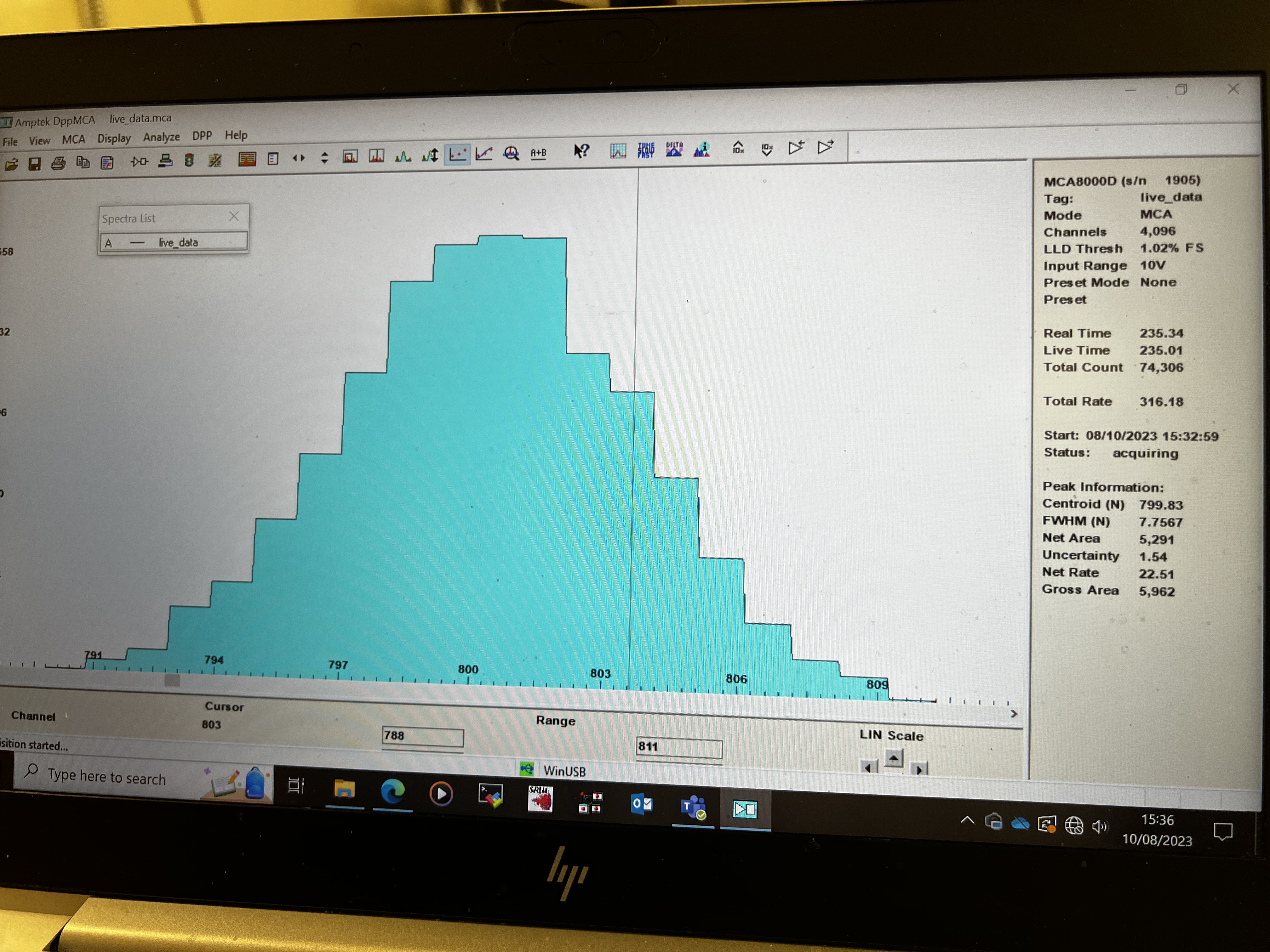
dE p+n junction strip # 4 ( of 0-15 )

pulser peak centroid = 799.8 ch
pulser peak width = 7.8 ch FWHM = 57 keV FWHM


E p+n junction strip # 4 ( of 0-15 )

pulser peak centroid = 864.8ch
pulser peak width = 3.5 ch FWHM = 26 keV FWHM


E n+n Ohmic strip # 4 ( of 0-15 )

pulser peak centroid = 913.0 ch
pulser peak width = 5.3 ch FWHM = 39 keV FWHM


Noise estimates are probably accurate to c. 10% level. |
| Attachment 1: 20230810_162959.JPG
|

|
| Attachment 2: IMG_2906.jpeg
|
|
| Attachment 3: 20230810_164219.JPG
|

|
|
56
|
Fri Aug 11 10:02:08 2023 |
TD, NS, AR | Noise |
Check RAL108 +/-15V PSU

Measured output voltages +15.21V -15.18V - OK

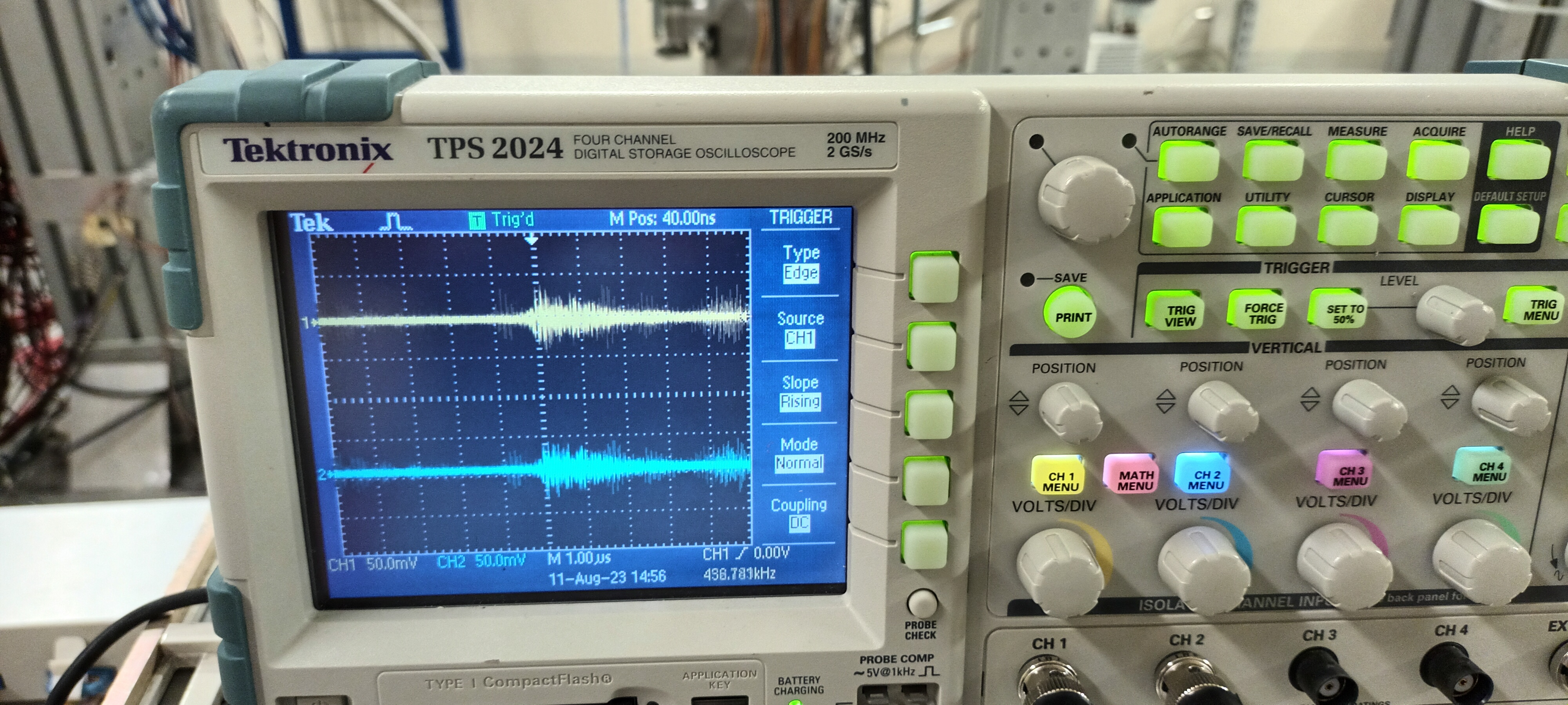
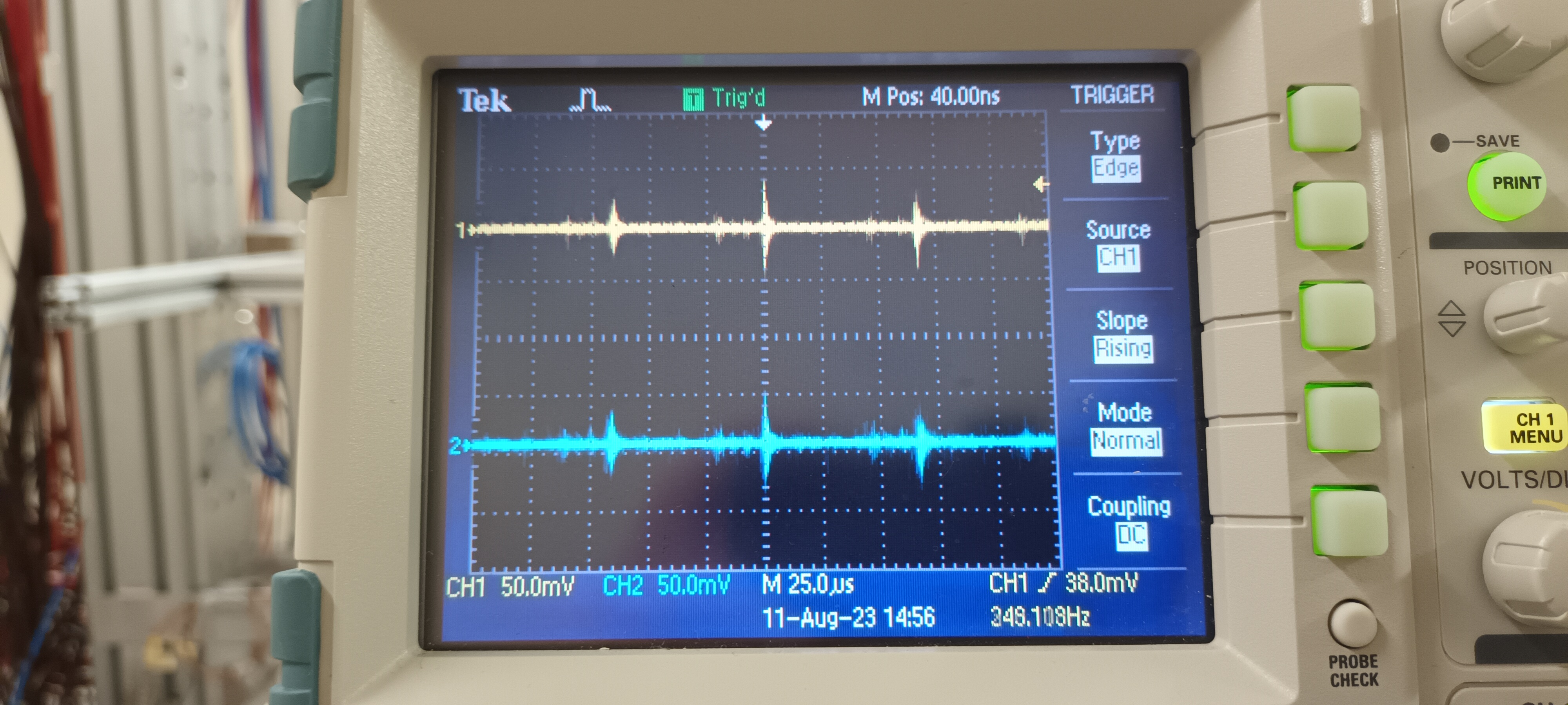
Observe output voltages with DSO ( ch #1 AC/1M +15V, ch #2 AC/1M -15V ) - see attachments 1 & 2

What we should observe is c. 1mV rms ( white ) noise but we clearly observe similar noise transients ( c. 60us period with HF structure ) to those observed at RAL108
outputs. The RAL108 preamplifier units do have RC filters on the +/-15V - typically c. 100 Ohm and 4.7uF. Some additional, inline filtering with a lower rolloff
frequency may be required.

>
> Observe c. 2mV p to p noise with DSO ( Z_in = 50 Ohm ) c. 60us period with HF structure. DSO connected to junction box via 34-way IDC - 16x Lemo-00 adaptor.
>
> Origin of noise upstream of 4x34-way to 8x16-way Junction Box. Not microphonics from Edwards RV5 Rotary Pump.
> No change observed with simple ground connections between NIM bin/+/-15V PSU/Junction Box and MSL type W1 preamplifier units/vacuum chamber/support assembly.
>
>
> Estimate of electronic noise
>
> Pulser BNC PB-5
>
> Amplitude 0.5V
> Attenuation x1
> Decay time 1ms
> Frequency 50Hz
>
> Preamplifier RAL108
> Output impedance 100 Ohm
> Sensitivity 20mV/MeV ( into high Z load ), 6.7mV/MeV ( into 50 Ohm load )
>
> Amplifier EG&G Ortec 571
> Input terminated by 50 Ohm
> Gain x1 (internal) x 1.0 (fine gain) x 50 (coarse gain ) = 50
> Shaping time 0.5us
>
> MCA Amptek 8000D
> Input FSR 10V
> 12 bit ADC
>
>
> Nominal gain = 6.7mV/MeV x 50 = 335mV/MeV
>
> 12 bit ADC input FSR = 10V / 0.335V/MeV = 29.85MeV FSR or 7.3keV/channel
>
>
> dE p+n junction strip # 4 ( of 0-15 )
>
> pulser peak centroid = 799.8 ch
> pulser peak width = 7.8 ch FWHM = 57 keV FWHM
>
>
> E p+n junction strip # 4 ( of 0-15 )
>
> pulser peak centroid = 864.8ch
> pulser peak width = 3.5 ch FWHM = 26 keV FWHM
>
>
> E n+n Ohmic strip # 4 ( of 0-15 )
>
> pulser peak centroid = 913.0 ch
> pulser peak width = 5.3 ch FWHM = 39 keV FWHM
>
>
> Noise estimates are probably accurate to c. 10% level. |
| Attachment 1: 20230811_104233.jpg
|
|
| Attachment 2: 20230811_104253.jpg
|
|
|
63
|
Tue Aug 15 10:17:39 2023 |
TD, NS | RAL108 +/-15V PSU test at EAR2, n_TOF Monday 14 August |
On the morning of Monday 14 August 2x RAL108 +/-15V PSUs were borrowed from the Edinburgh equipment in the ISOLDE hall to check whether the same transient
noise is observed at the +/-15V PSU outputs.


PSU #2 Farnell MX2

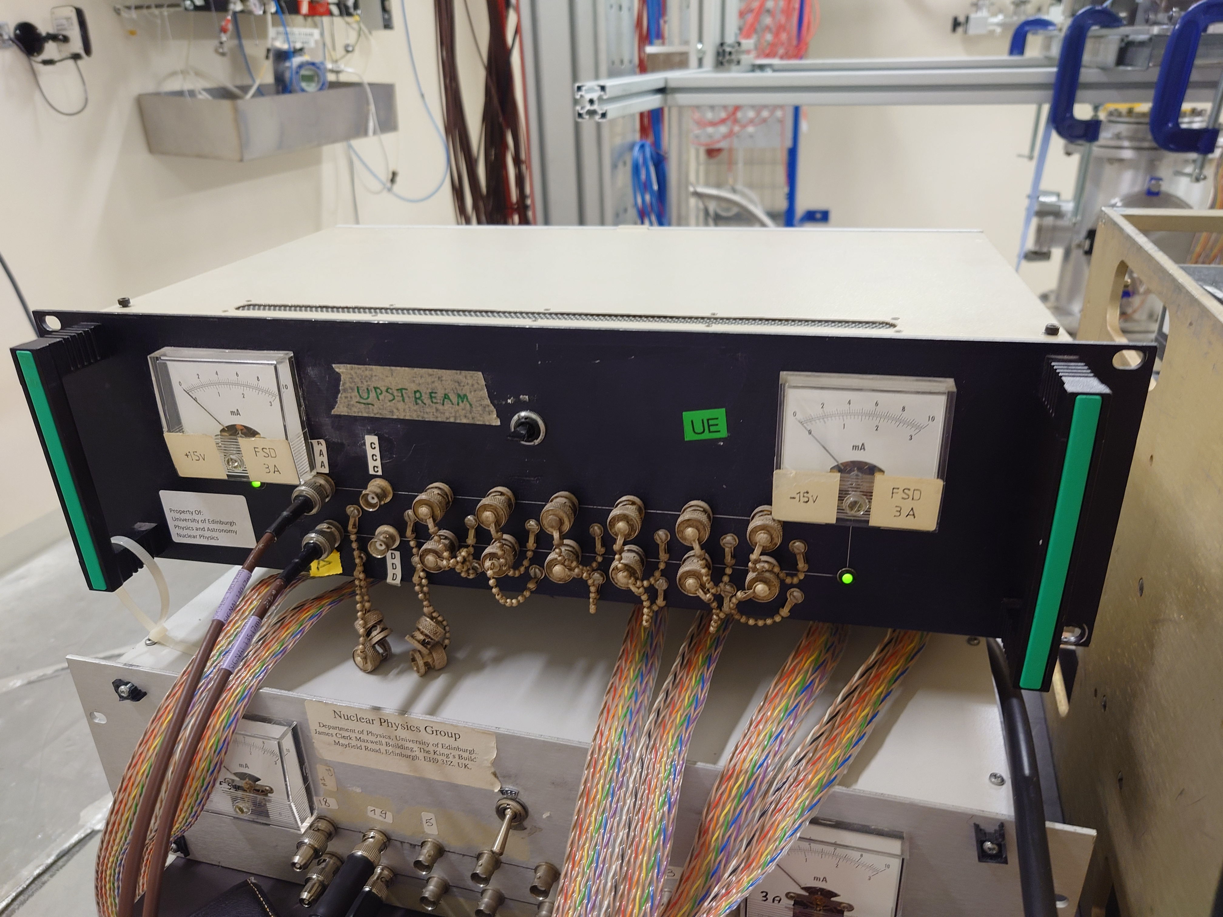
Setup - attachment 1

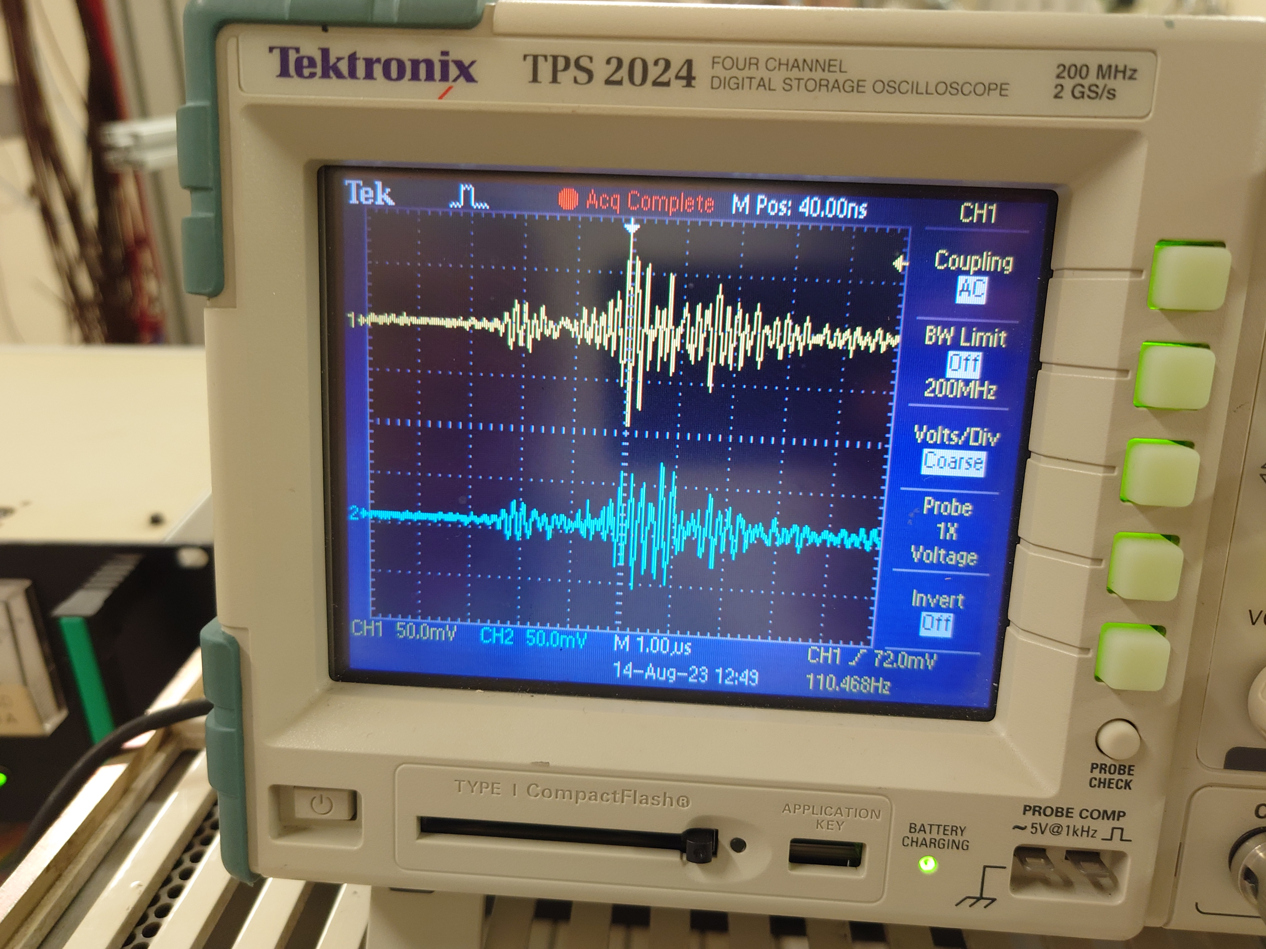
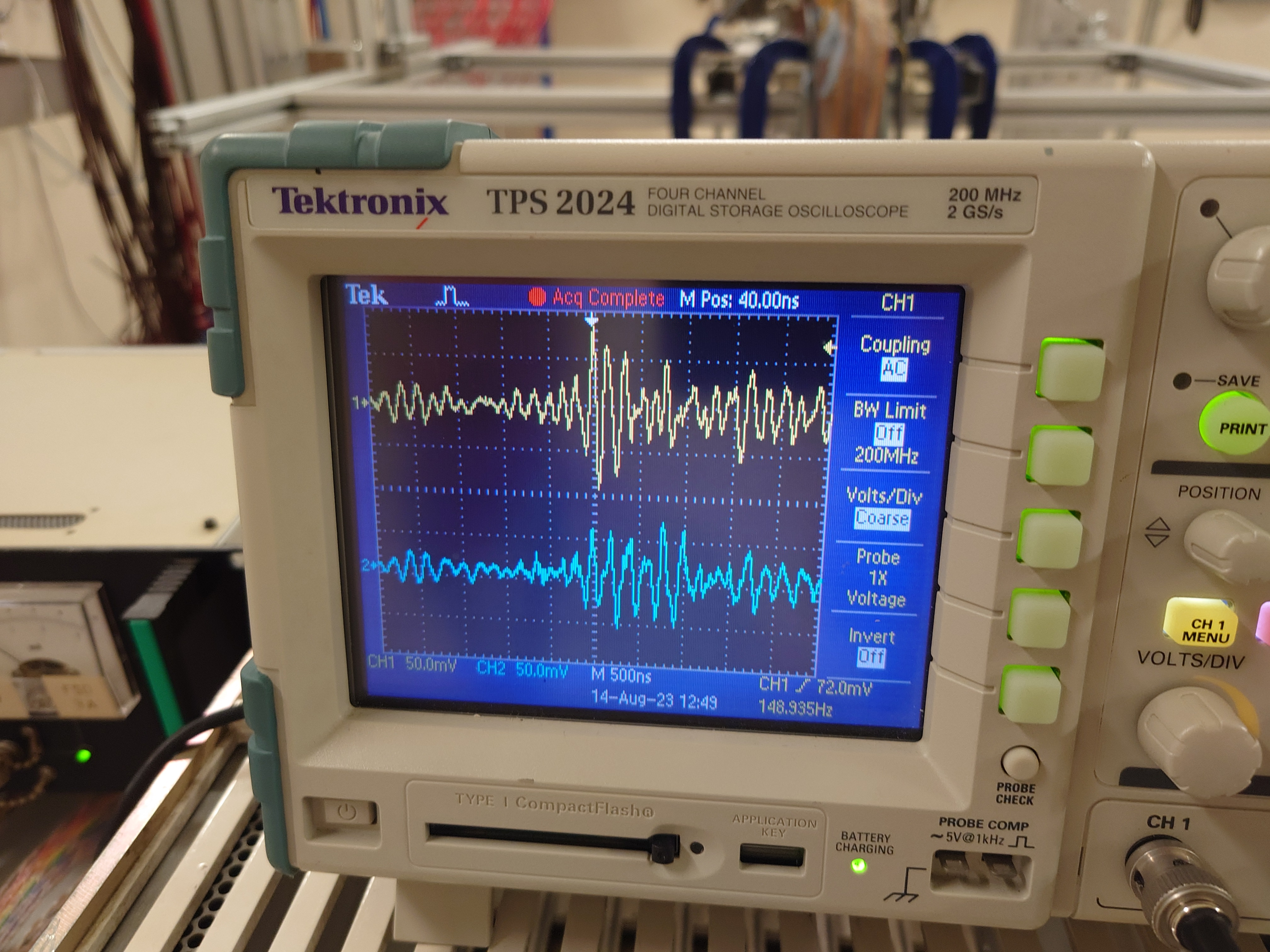
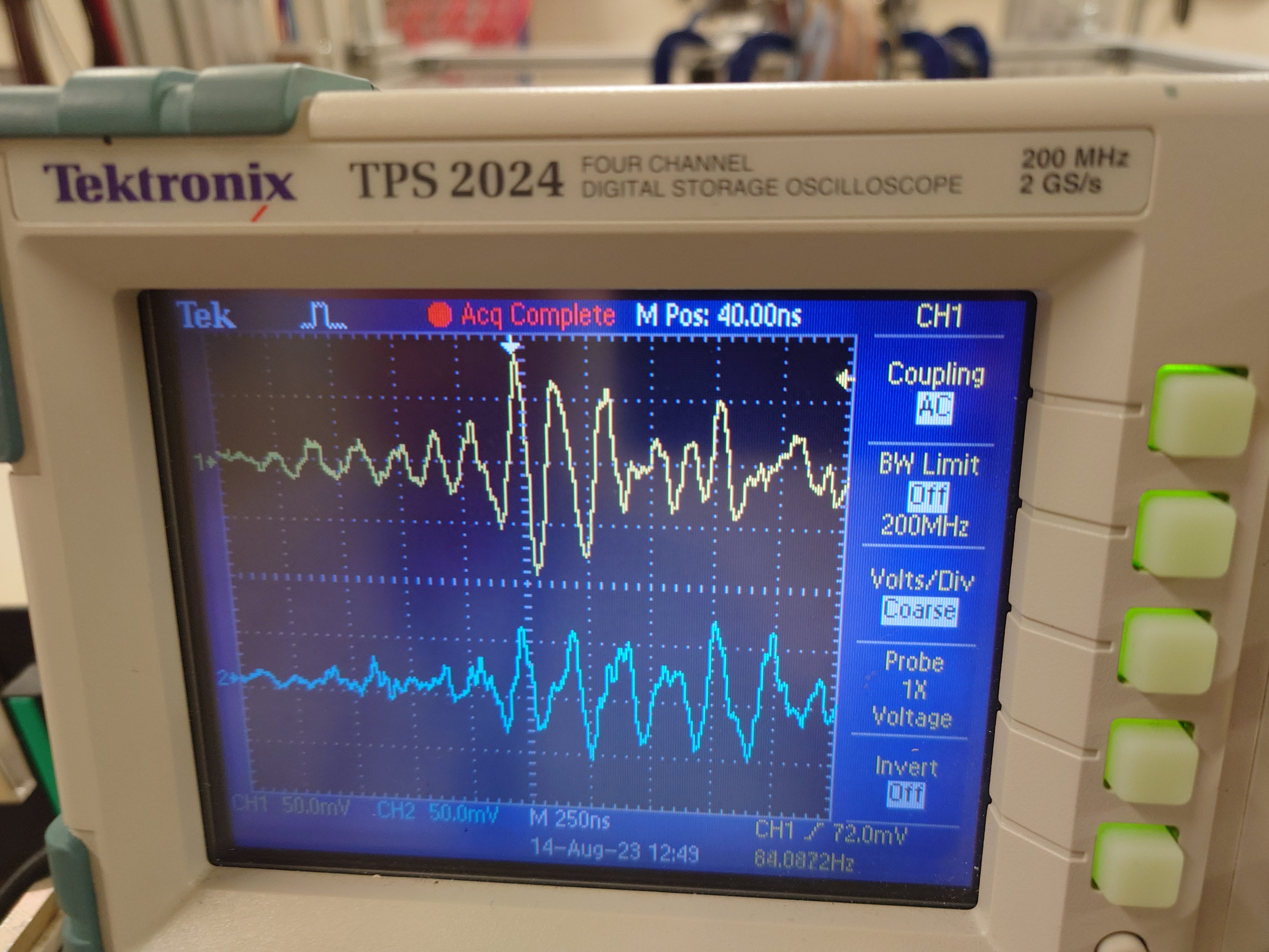
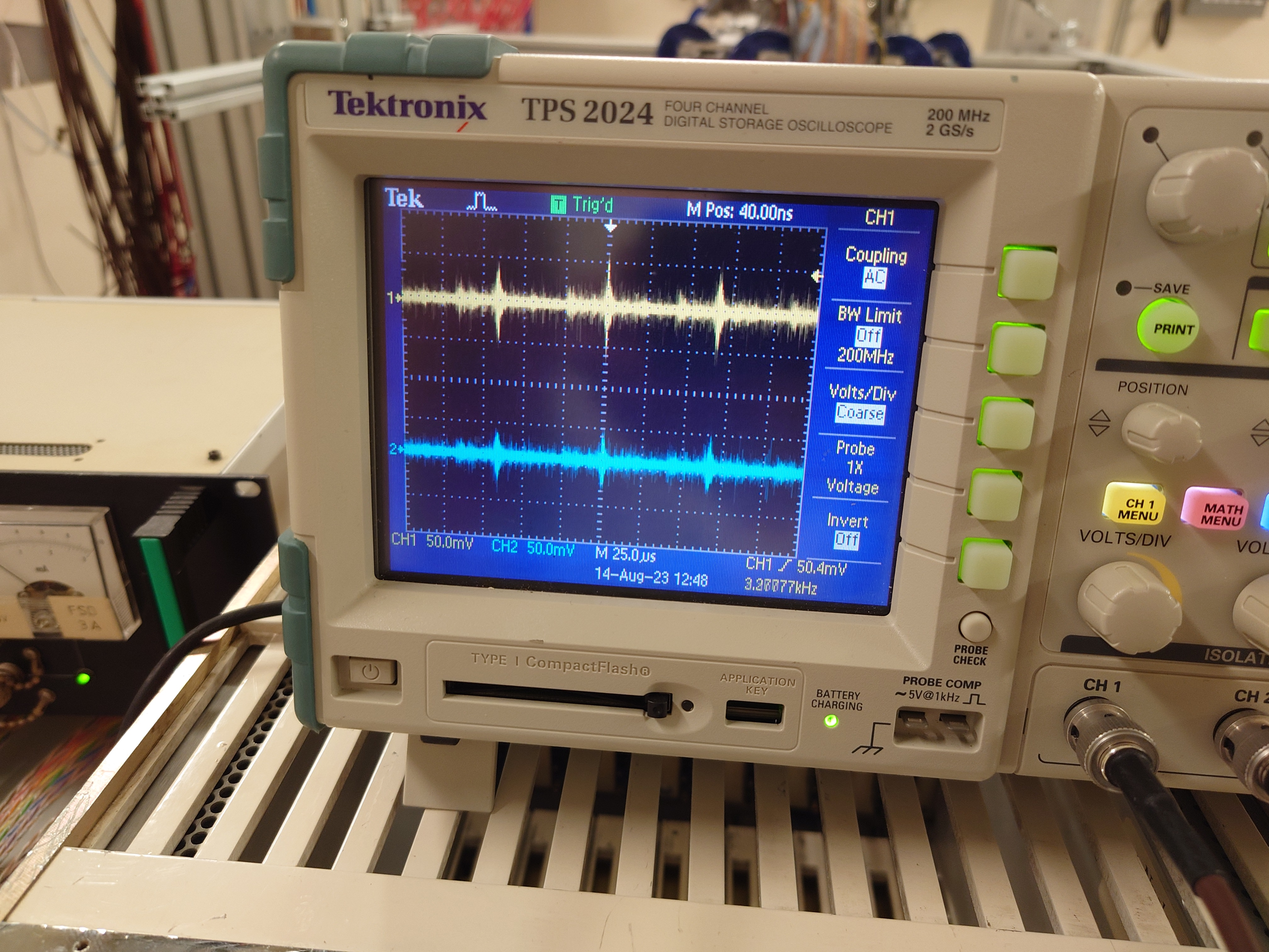
DSO ch#1 +15V AC/1M, ch#2 -15V AC/1M - y: 50mV/div x: 1us, 500ns, 250ns & 25us/div - attachments 2-5


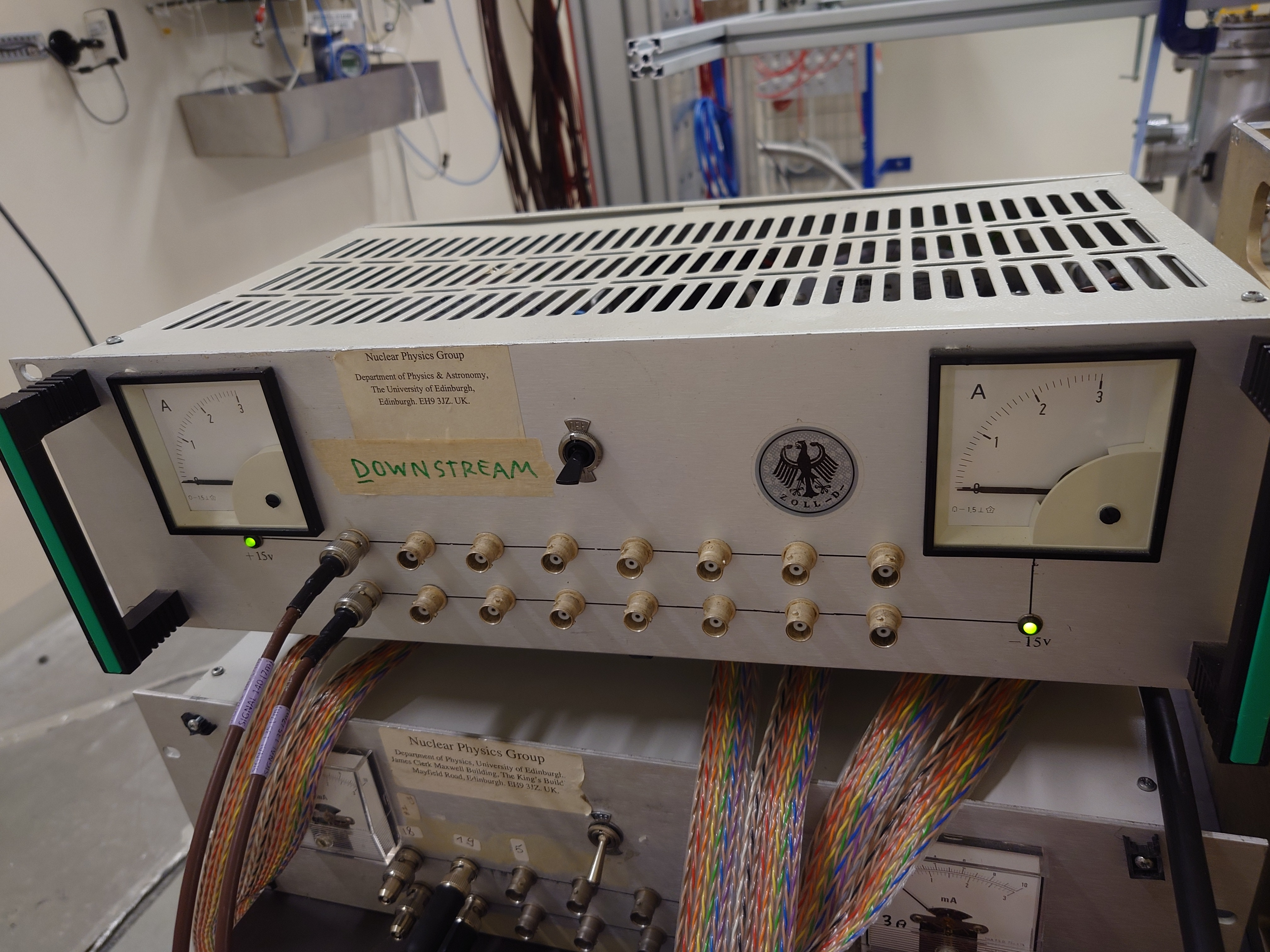
PSU #1 Coutant HSC15-3.0

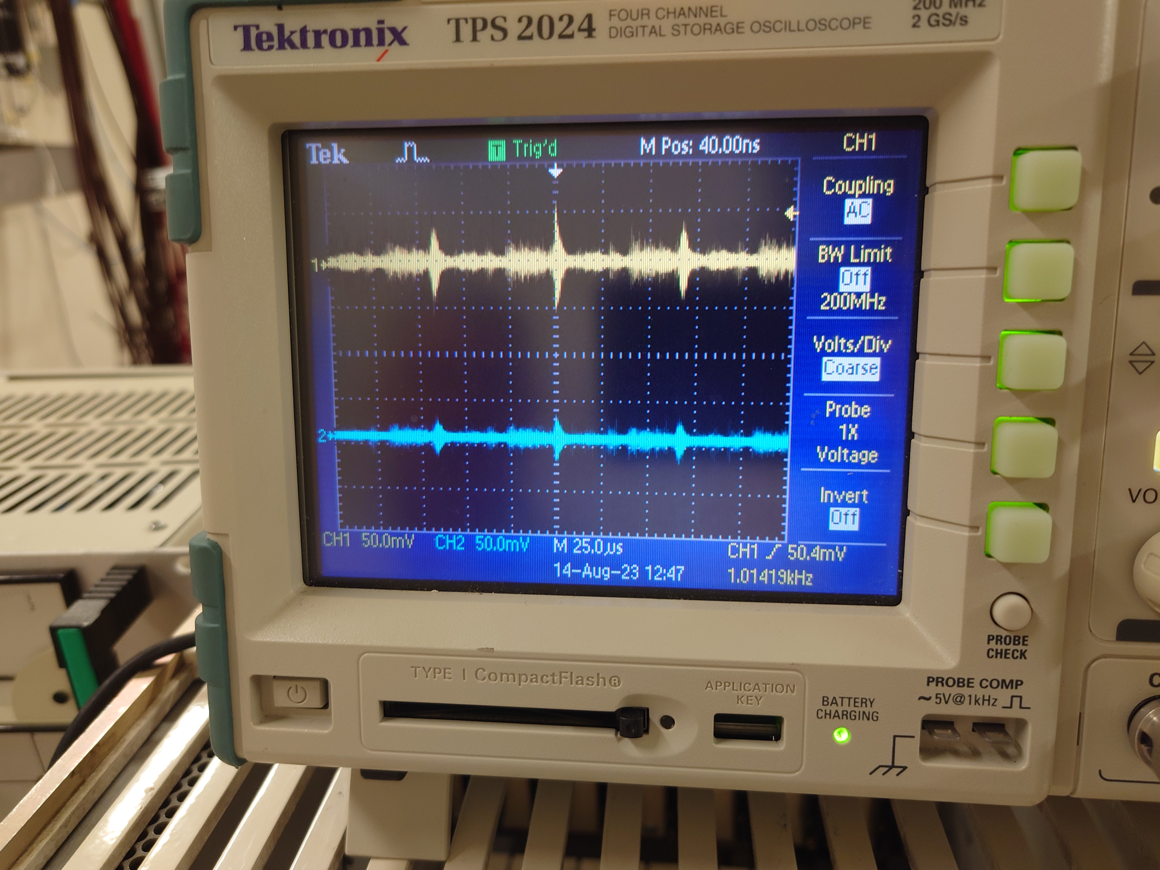
Setup - attachment 6

DSO ch#1 +15V AC/1M, ch#2 -15V AC/1M - y: 50mV/div x: 25us/div - attachment 7


Conclusion

Observe same amplitude and HF structure with all 3x RAL108 +/-15V PSUs |
| Attachment 1: 20230814_083448.jpg
|
|
| Attachment 2: 20230814_083549.jpg
|
|
| Attachment 3: 20230814_083556.jpg
|
|
| Attachment 4: 20230814_083601.jpg
|
|
| Attachment 5: 20230814_083445.jpg
|
|
| Attachment 6: 20230814_083323.jpg
|
|
| Attachment 7: 20230814_083319.jpg
|
|
|
64
|
Tue Aug 15 11:41:27 2023 |
TD, NS | Monday 14 August - vacuum chamber pressure |
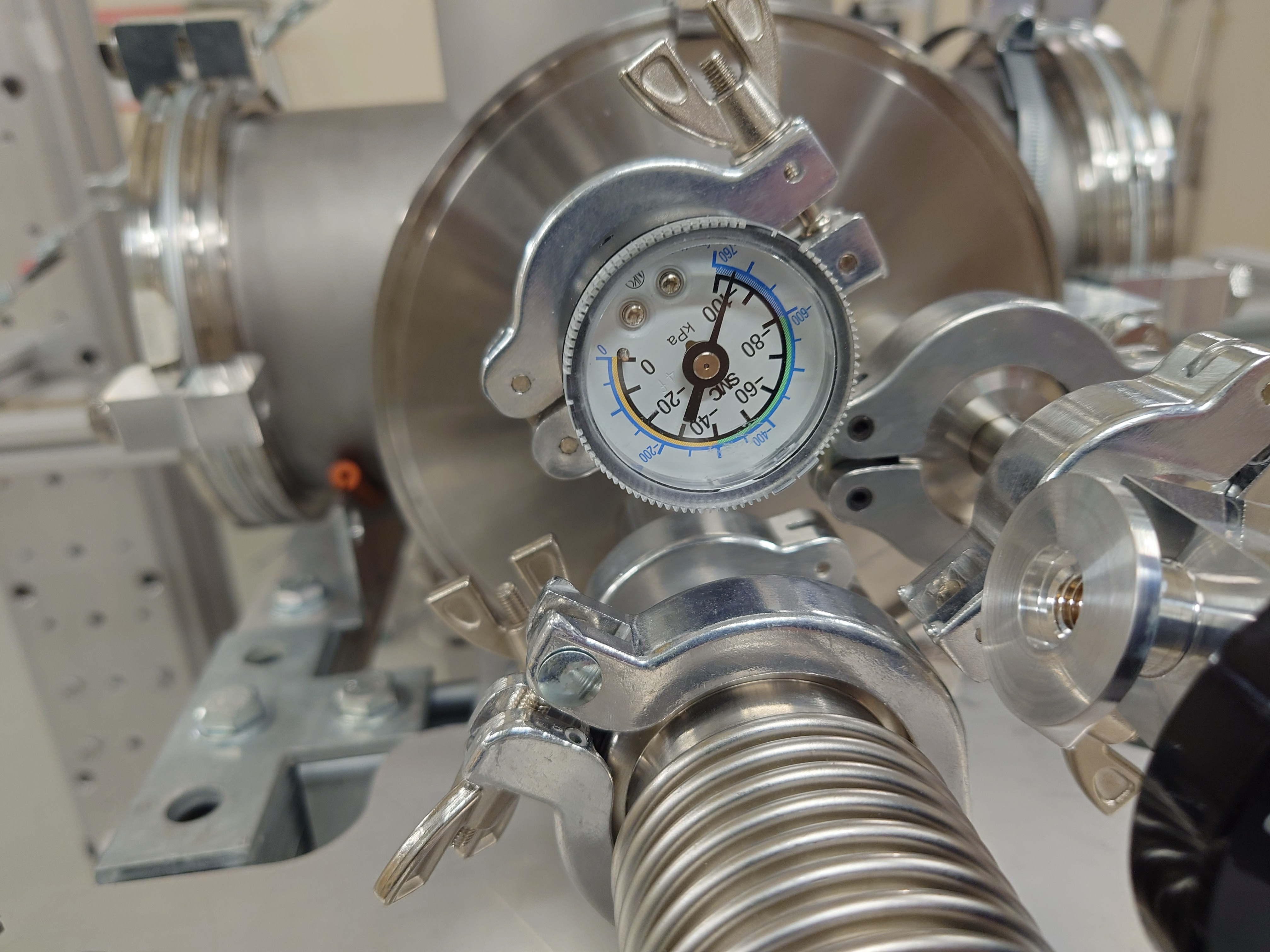
08.35 Vacuum chamber pressure OK - see attachment 1 |
| Attachment 1: 20230814_083514.jpg
|
|
|
43
|
Thu Jul 27 11:53:52 2023 |
TD | MSL type W1 detector data for 26Al(n,X) experiment EAR2, n_TOF |
MSL type W1(SS)-20

3186-9  20um Depletion voltage 3V Operating voltage 6V
3585-12 20um Depletion voltage 2V Operating voltage 4V

MSL type W1(DS)-150

3458-1 157um Depletion voltage 22V Operating voltage 52V
3458-4 144um Depletion voltage 18V Operating voltage 48V |
|
62
|
Mon Aug 14 11:00:13 2023 |
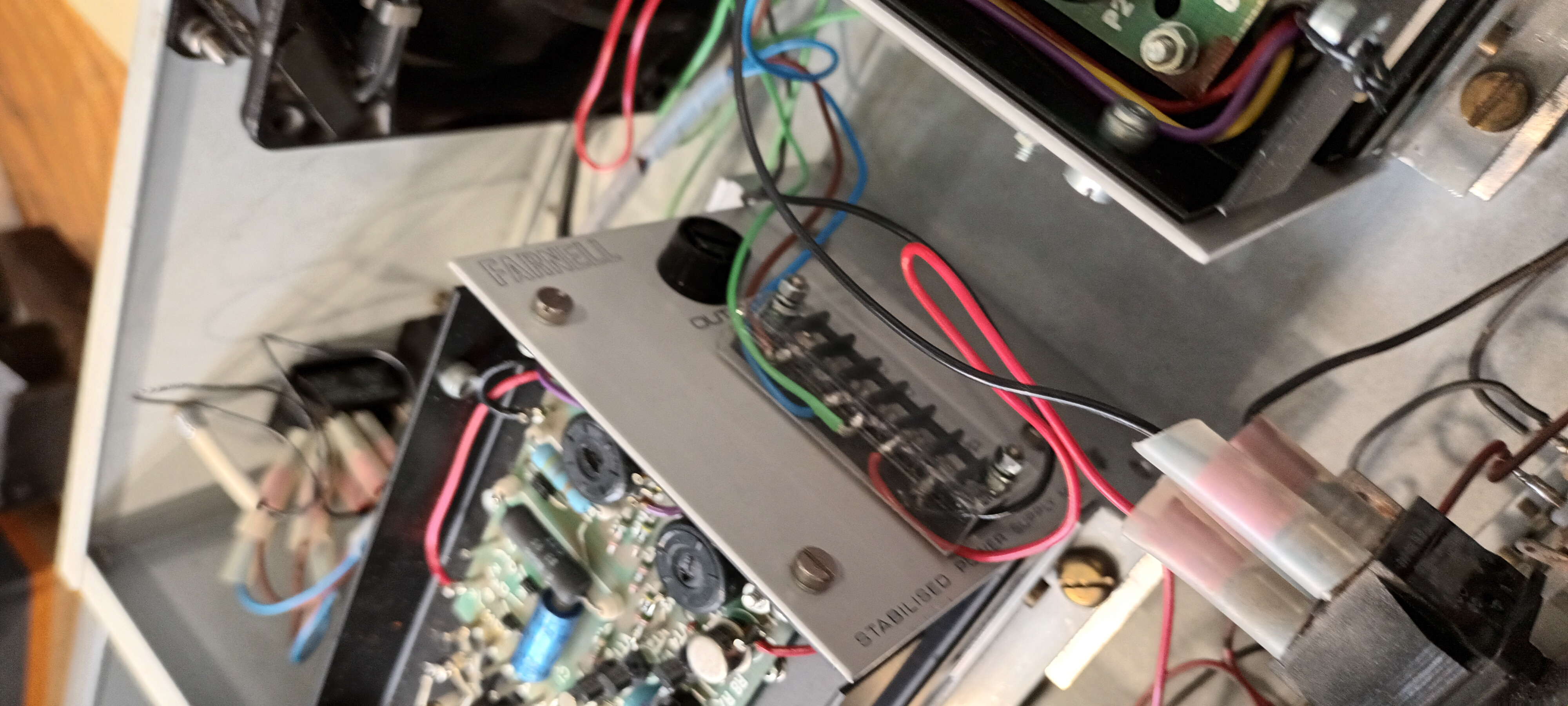
TD | RAL108 +/-15V PSU test in ISOLDE hall |
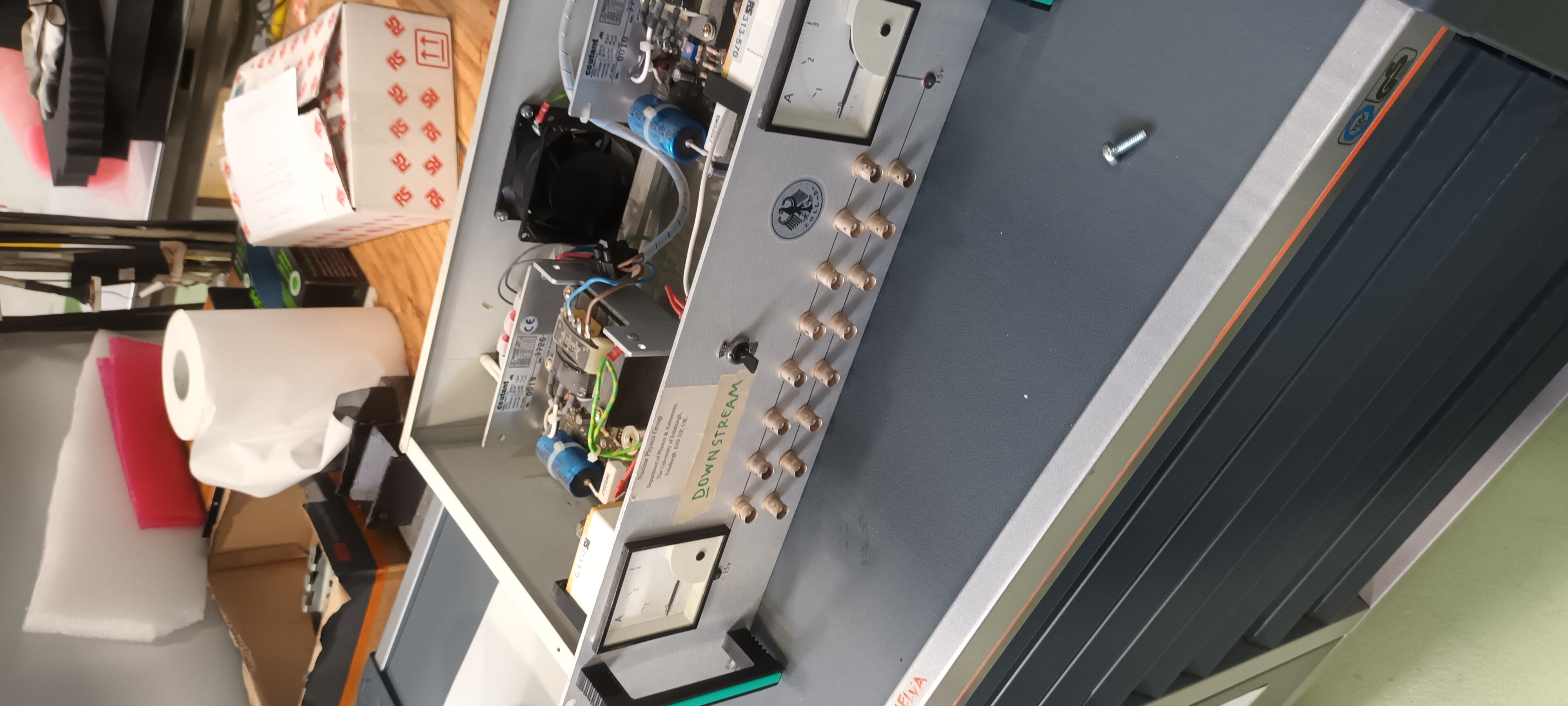
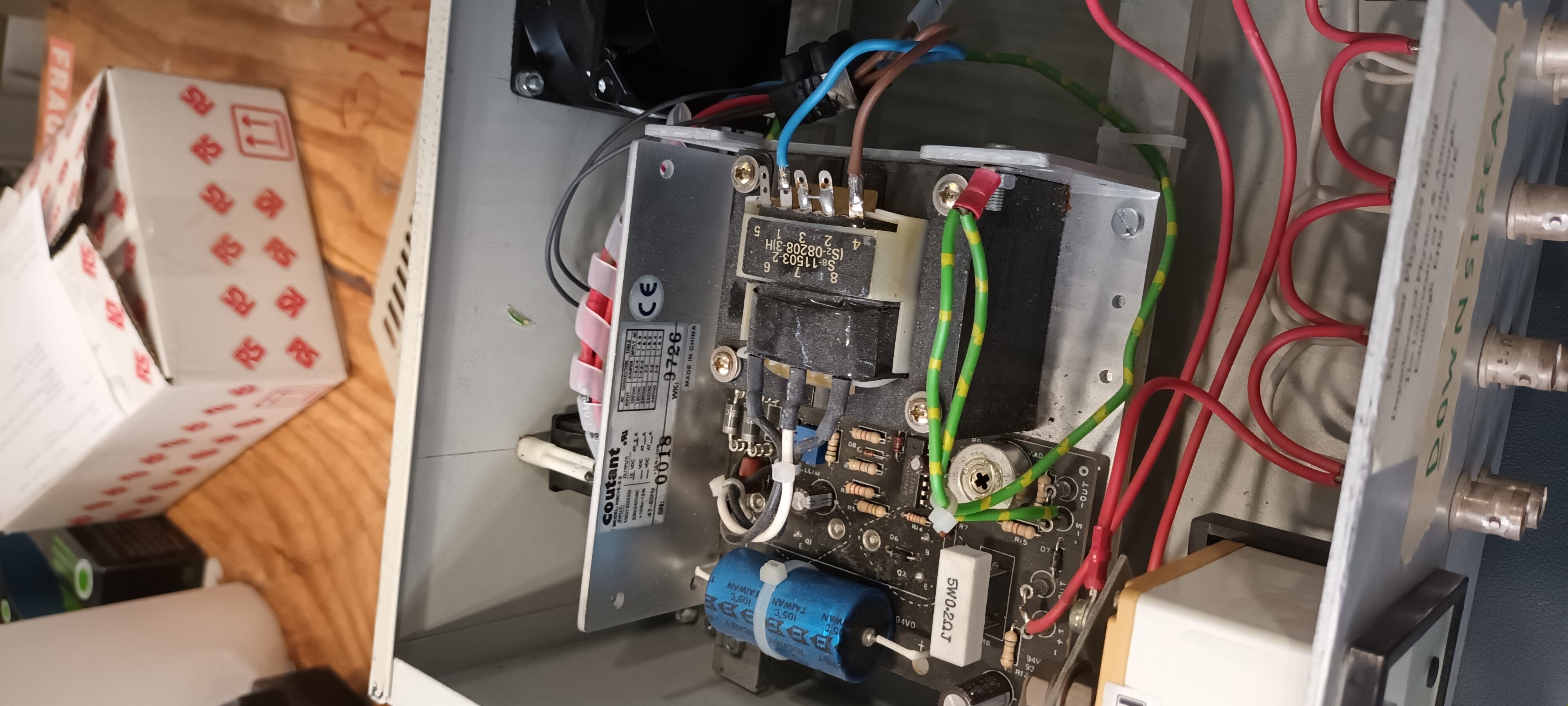
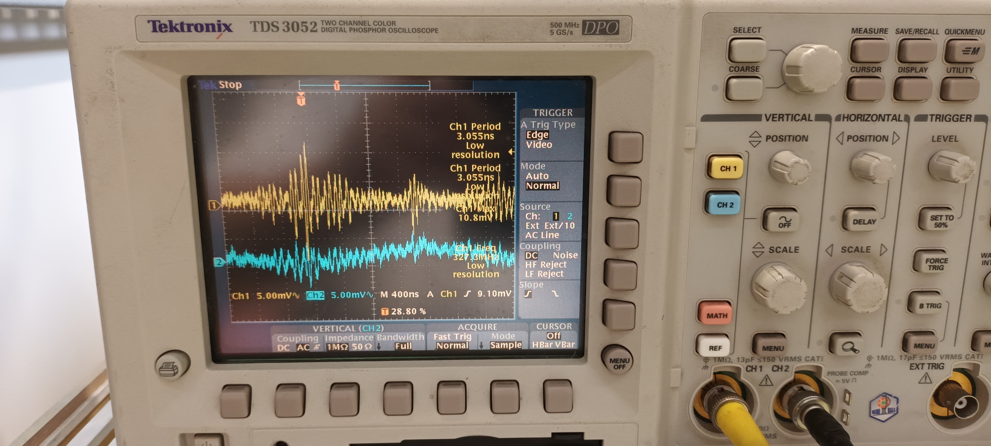
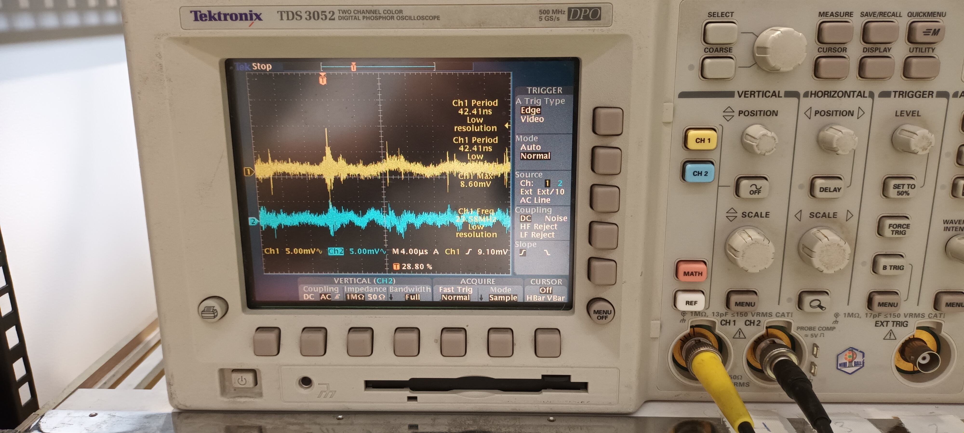
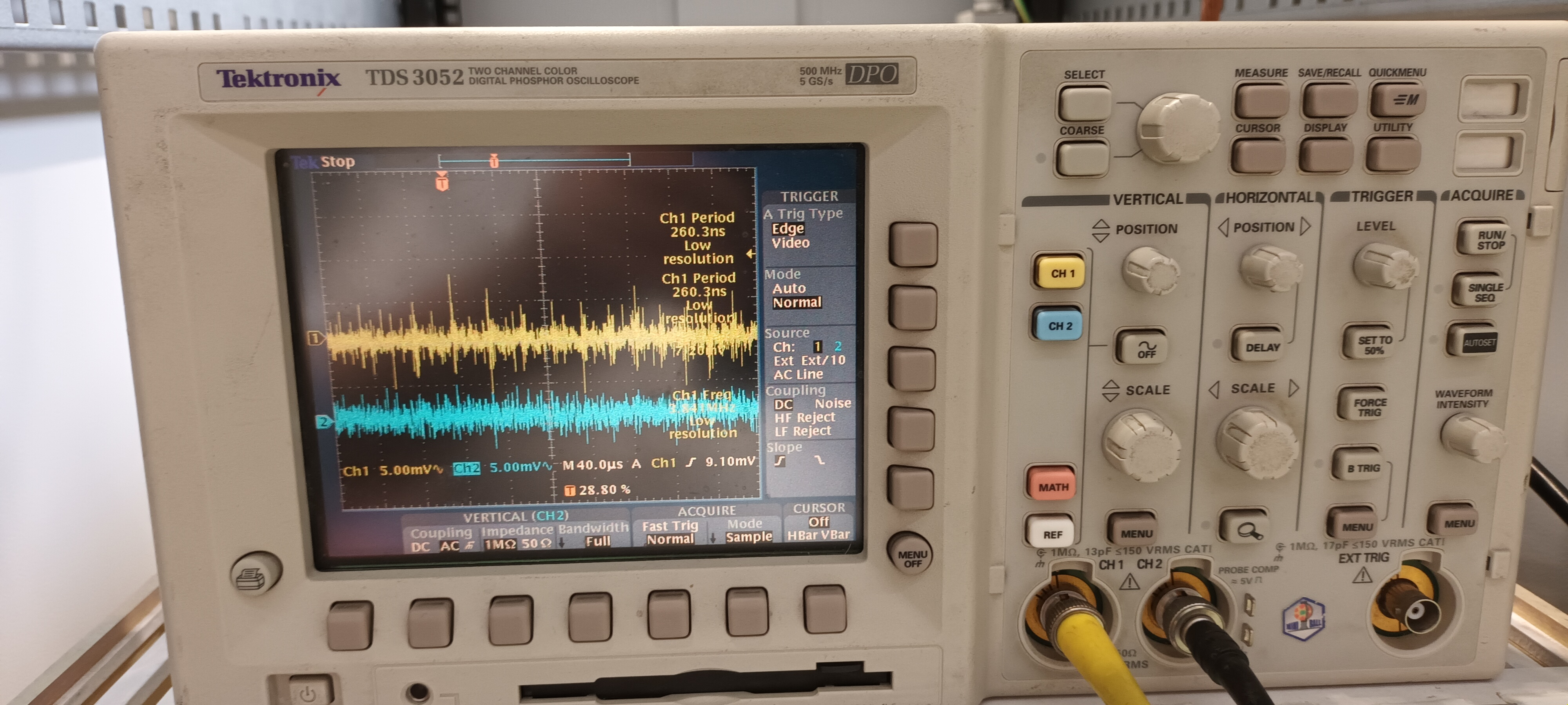
This morning 2x RAL108 +/-15V PSUs were borrowed from the Edinburgh equipment in the ISOLDE hall to check whether the same transient noise is observed at the +/-15V PSU
outputs - this was confirmed. See https://elog.ph.ed.ac.uk/nToF/63

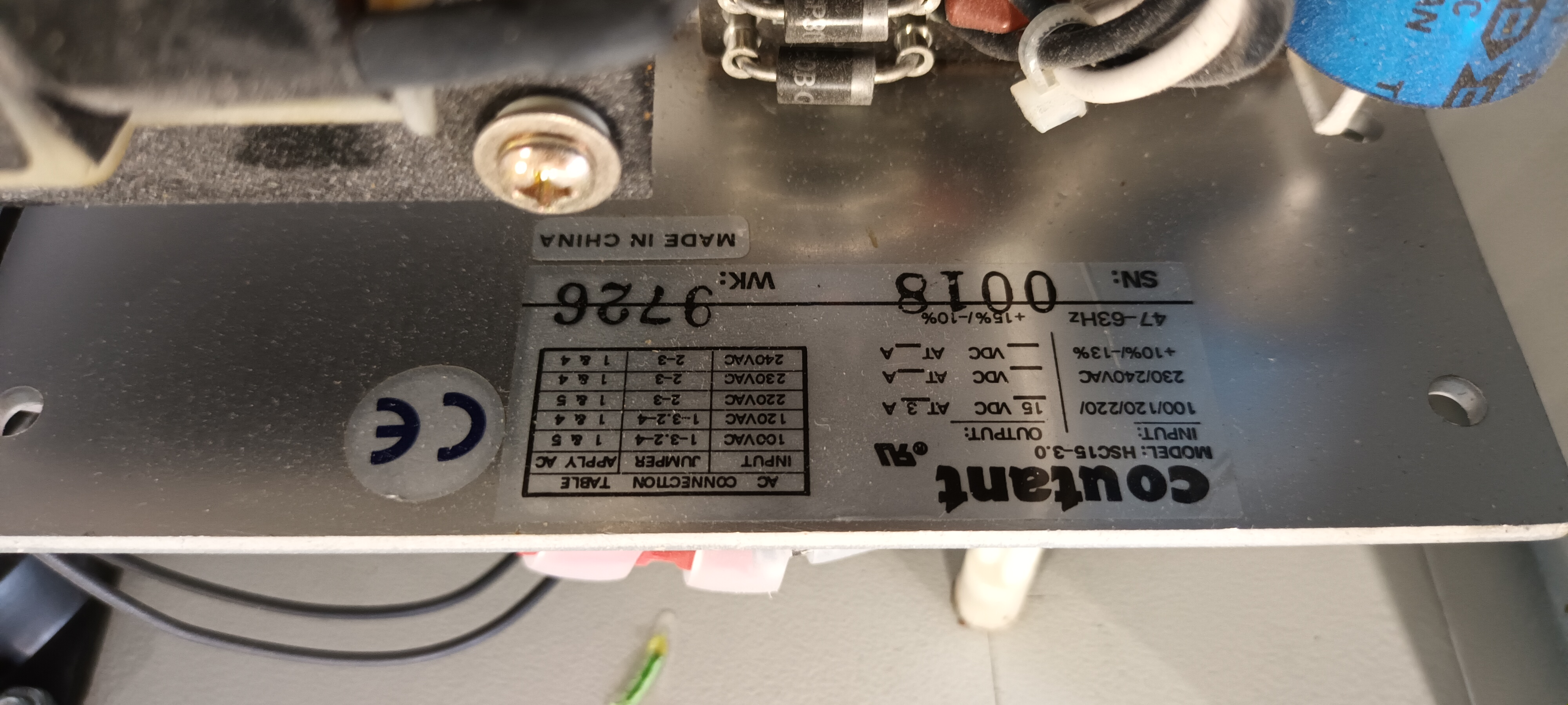
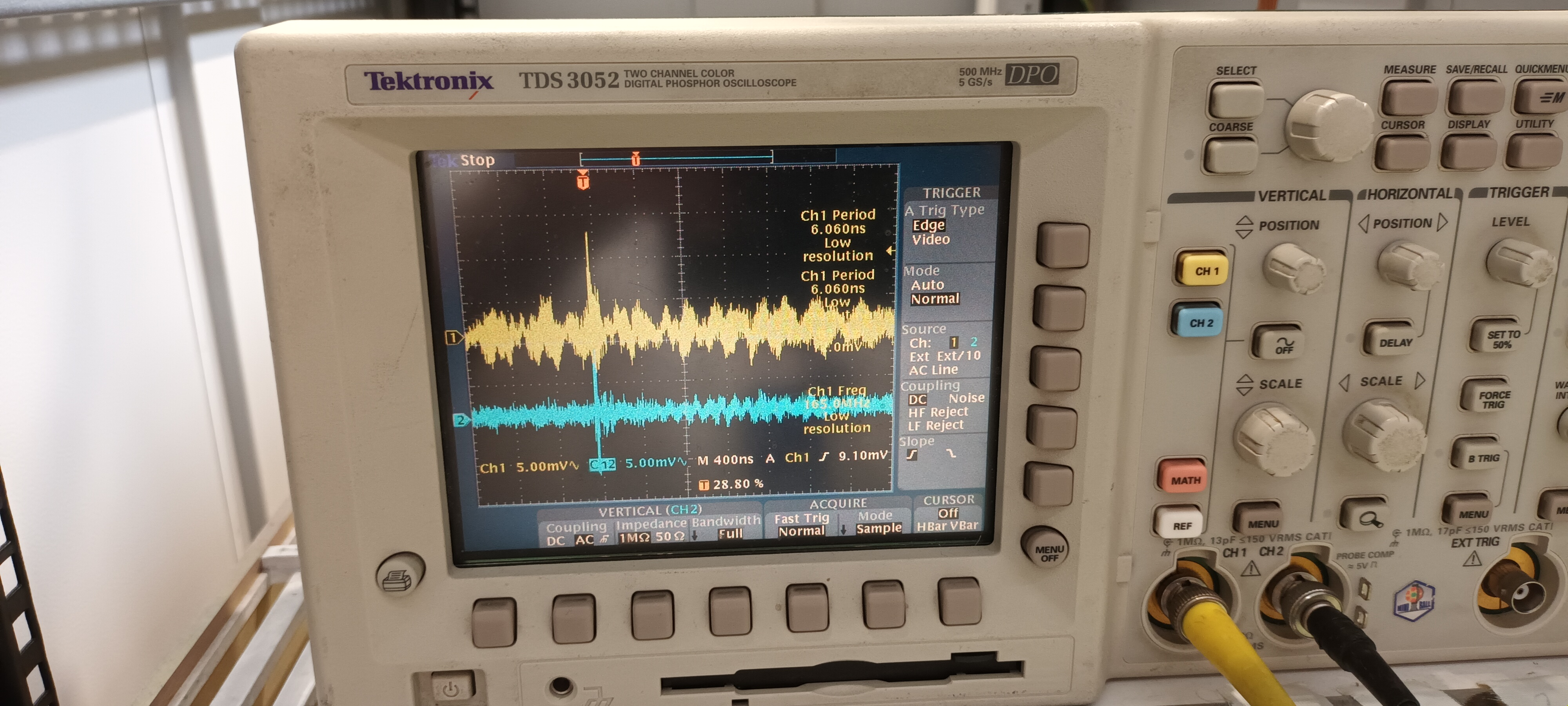
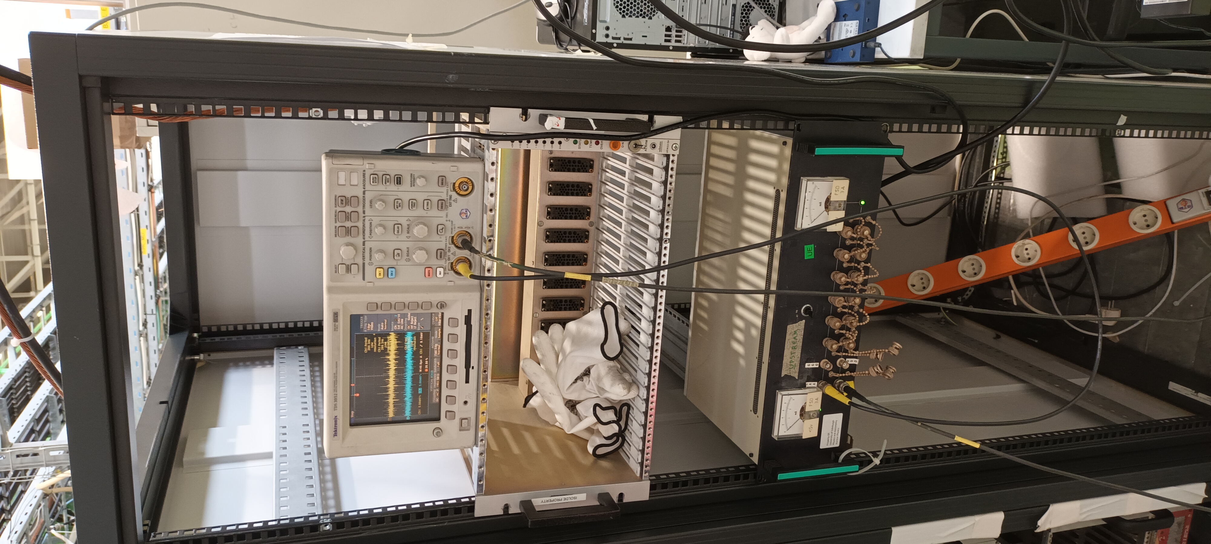
Following this test the same 2x RAL108 +/-15V PSUs were tested in the ISOLDE hall ( 19" rack adjacent to the HIE-ISOLDE GP scattering chamber ).


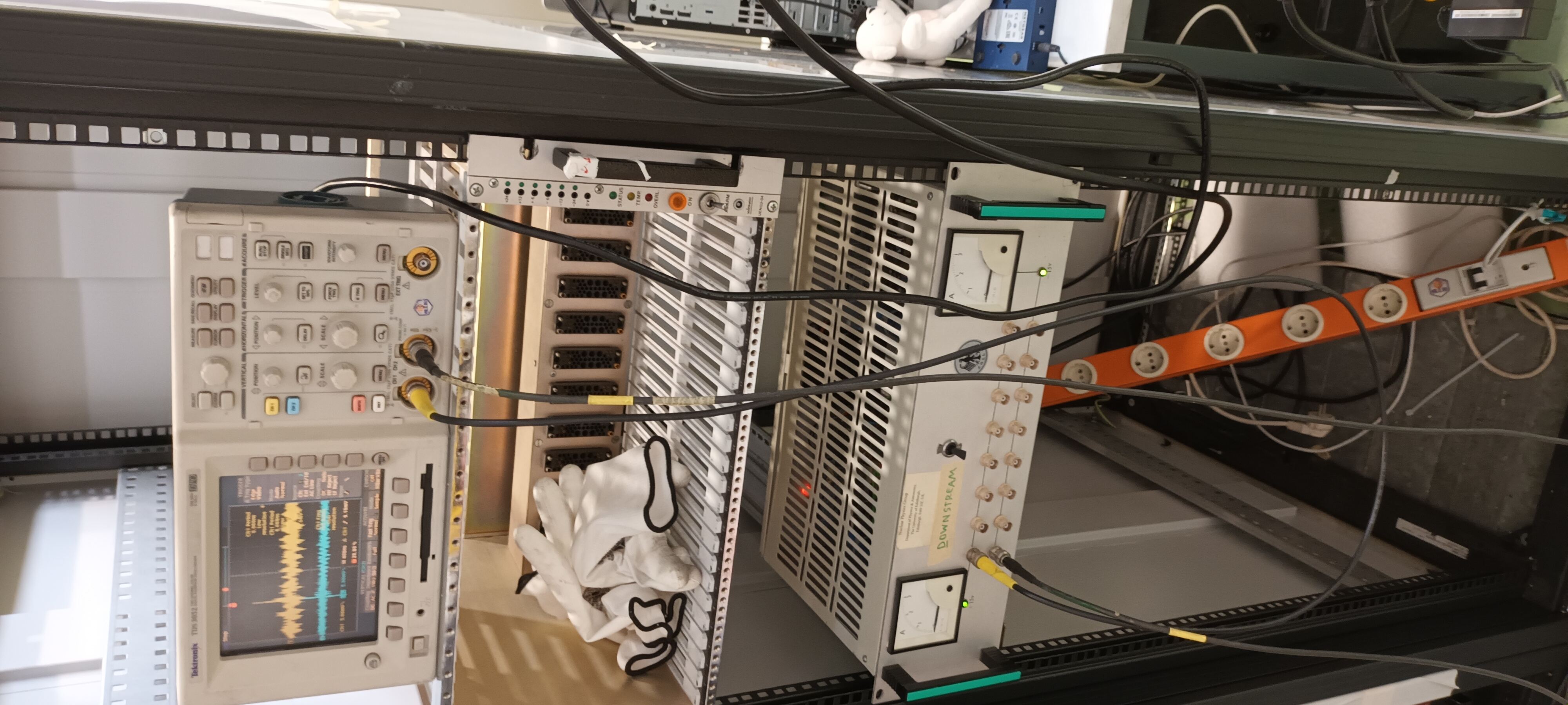
PSU #1 Coutant HSC15-3.0

Setup and PSU details - attachments 1-4

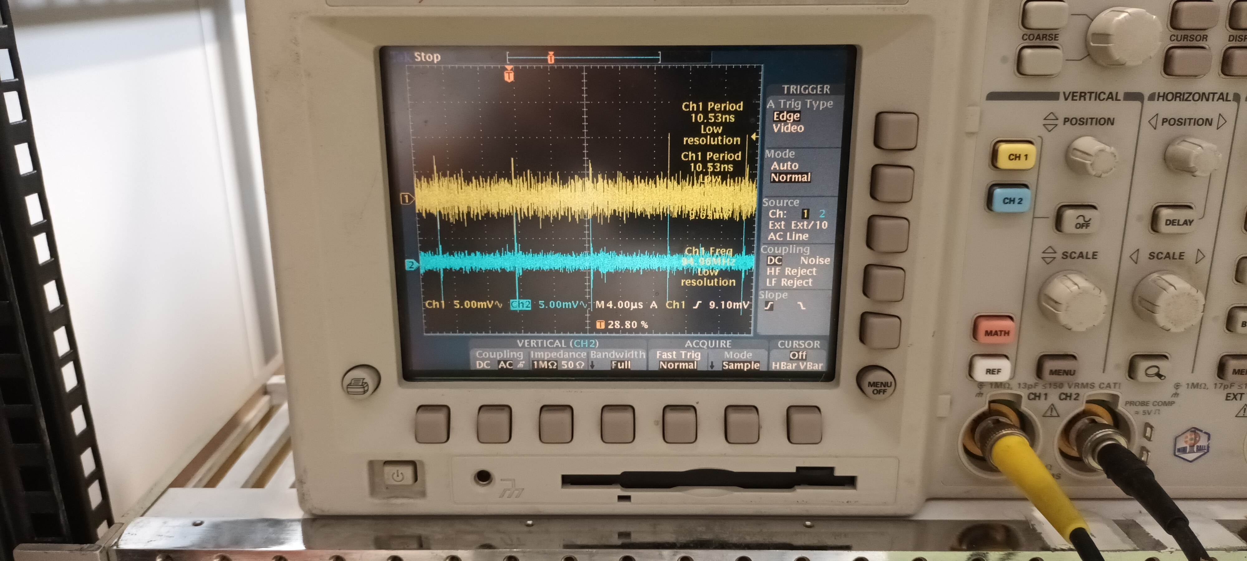
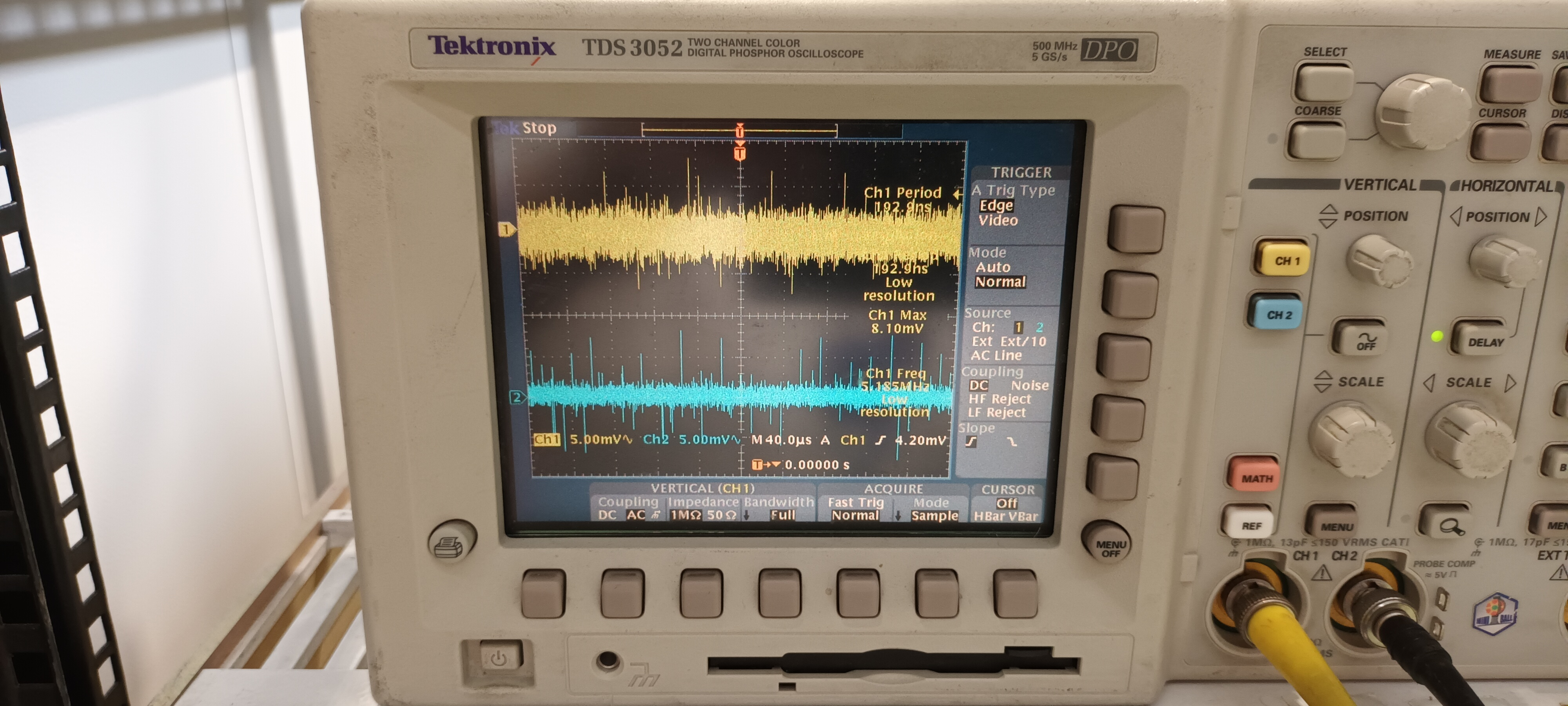
DSO ch#1 +15V AC/1M, ch#2 -15V AC/1M - y: 5mV/div x: 400ns, 4us & 40us/div - attachments 5-7


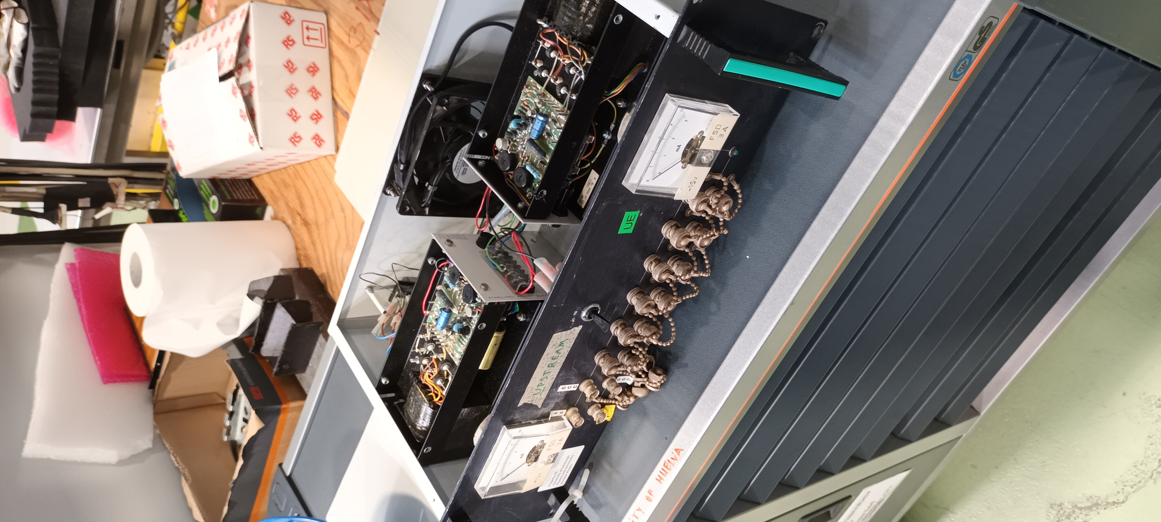
PSU #2 Farnell MX2

Setup and PSU details - attachments 8-10

DSO ch#1 +15V AC/1M, ch#2 -15V AC/1M - y: 5mV/div x: 400ns, 4us & 40us/div - attachments 11-13


Conclusion

The noise of the 2x RAL108 +/-15V PSUs differed somewhat ( frequency and structure of HF transients ) from each other in the ISOLDE test.

Compared to the EAR2, n_TOF test the amplitudes were c. 10x smaller and the HF transient frequency and structure differed.

This appears to confirm that the primary problem is the ac mains power in EAR2, n_TOF - input and/or output filtering is required. |
| Attachment 1: 20230814_110402.jpg
|
|
| Attachment 2: 20230814_111029.jpg
|
|
| Attachment 3: 20230814_111128.jpg
|
|
| Attachment 4: 20230814_111216.jpg
|
|
| Attachment 5: 20230814_110410.jpg
|
|
| Attachment 6: 20230814_110424.jpg
|
|
| Attachment 7: 20230814_110516.jpg
|
|
| Attachment 8: 20230814_110053.jpg
|
|
| Attachment 9: 20230814_110723.jpg
|
|
| Attachment 10: 20230814_110738.jpg
|
|
| Attachment 11: 20230814_110158.jpg
|
|
| Attachment 12: 20230814_110142.jpg
|
|
| Attachment 13: 20230814_110105.jpg
|
|
|
66
|
Sat Aug 19 14:14:26 2023 |
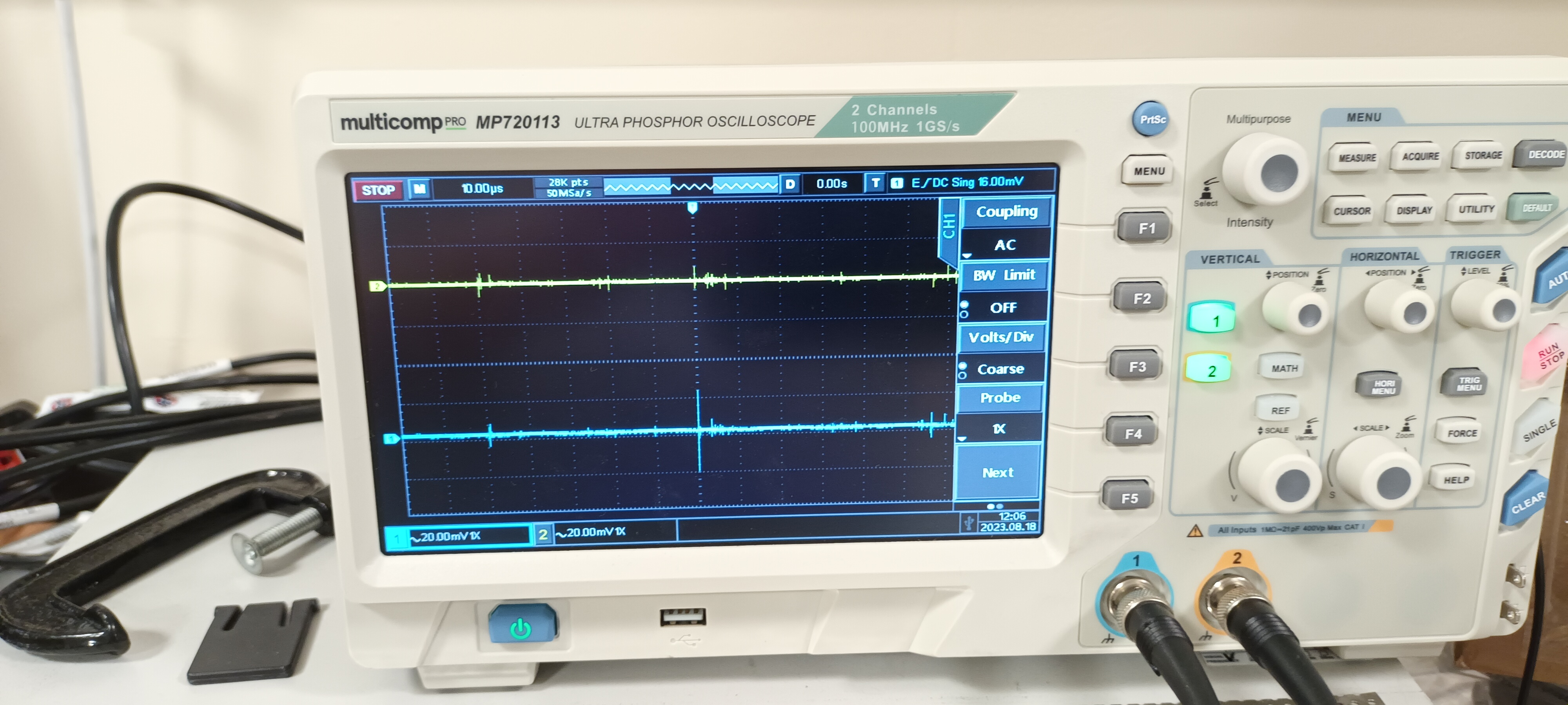
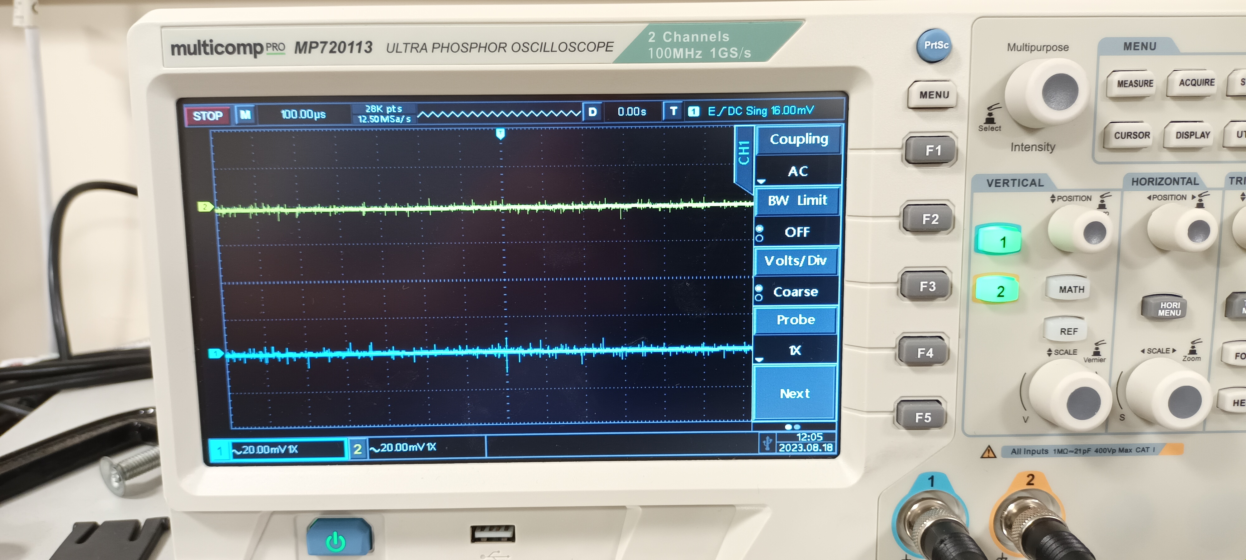
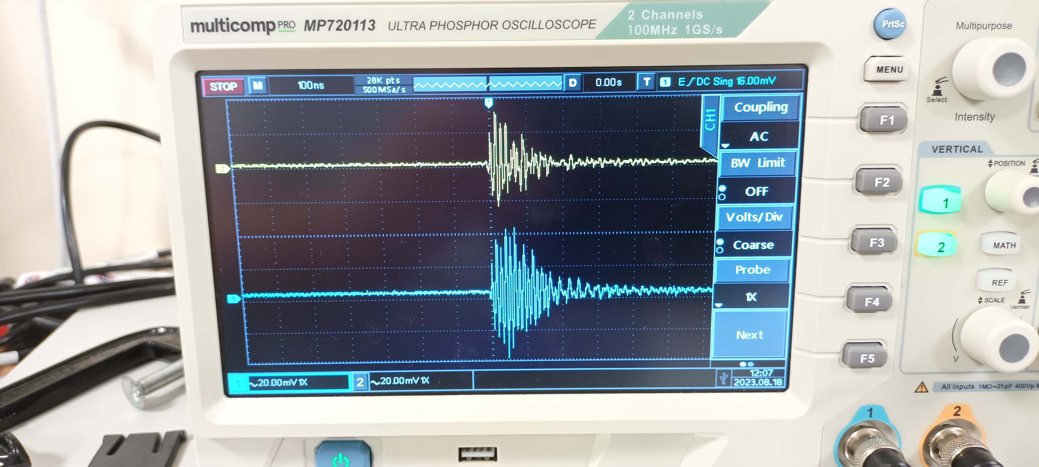
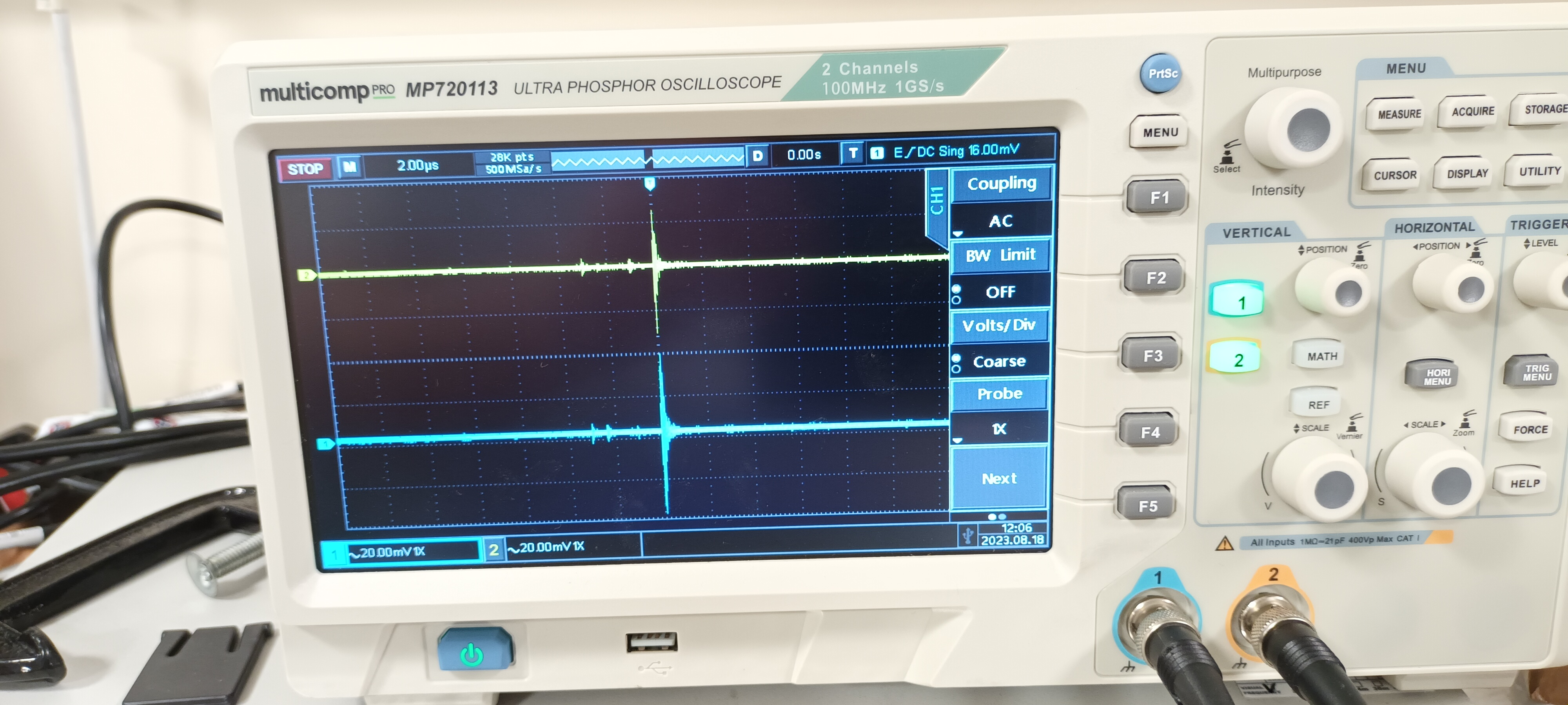
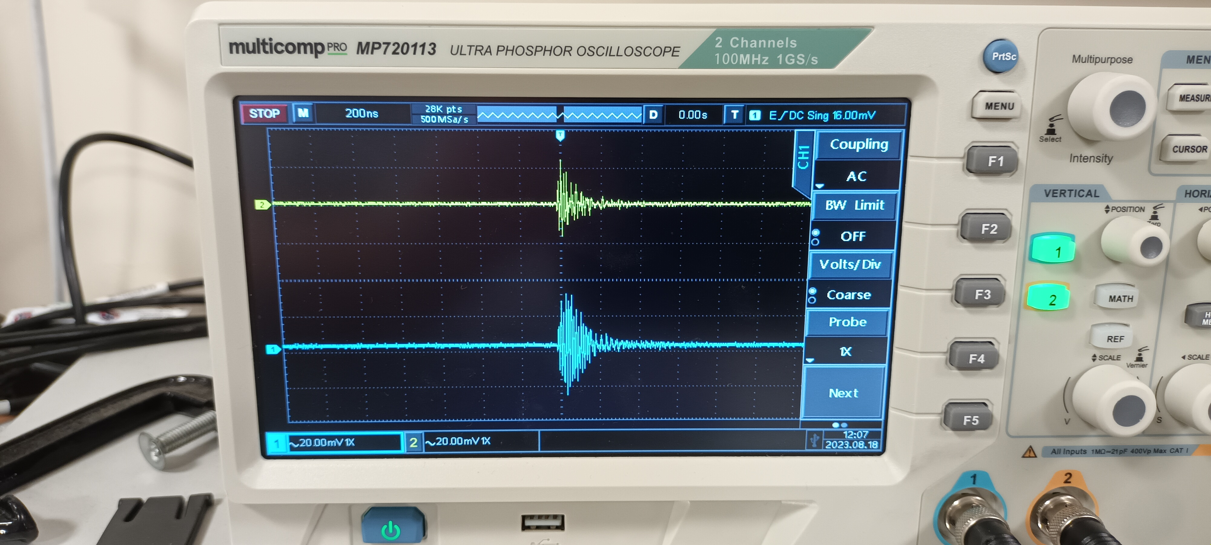
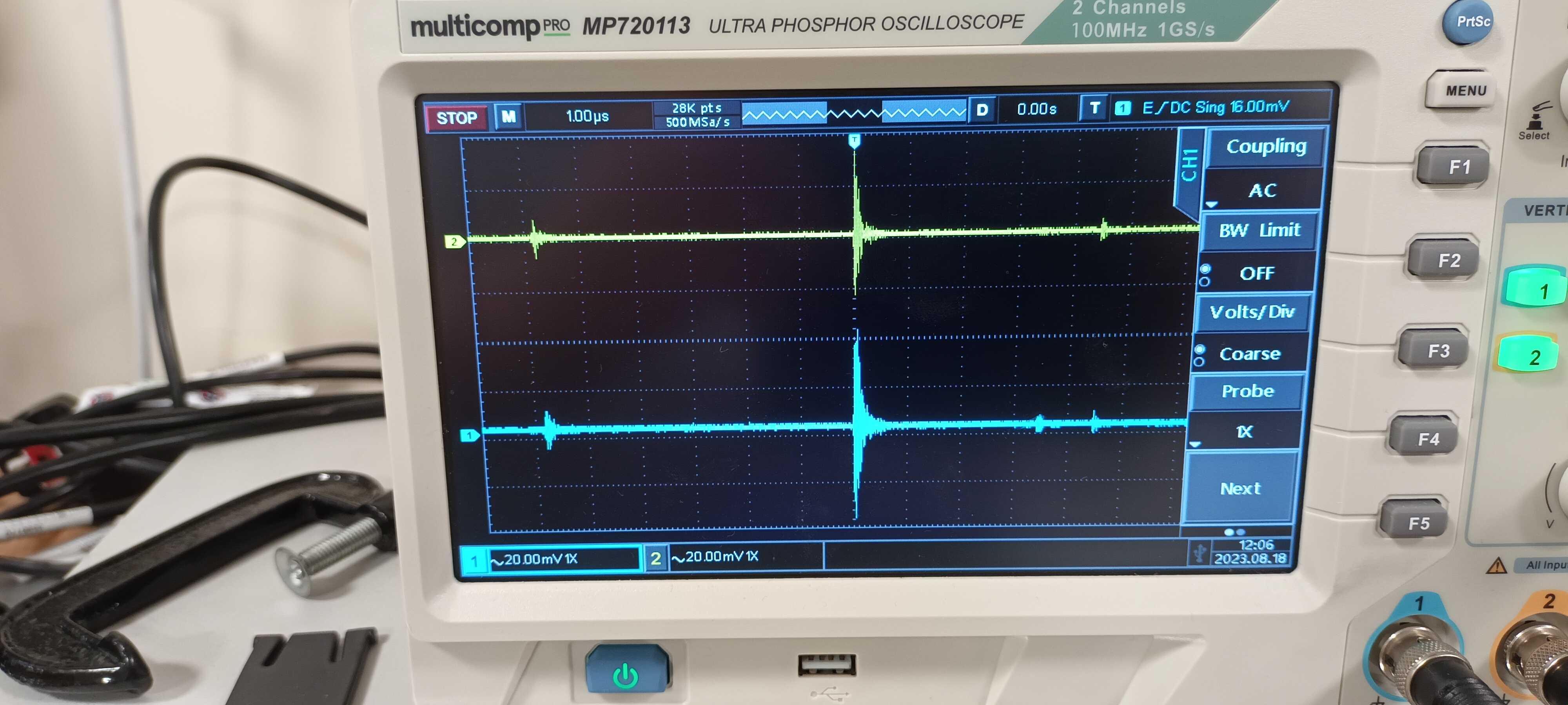
TD | RAL108 +/-15V PSU test - JCMB 18.8.23 |
PSU Calex

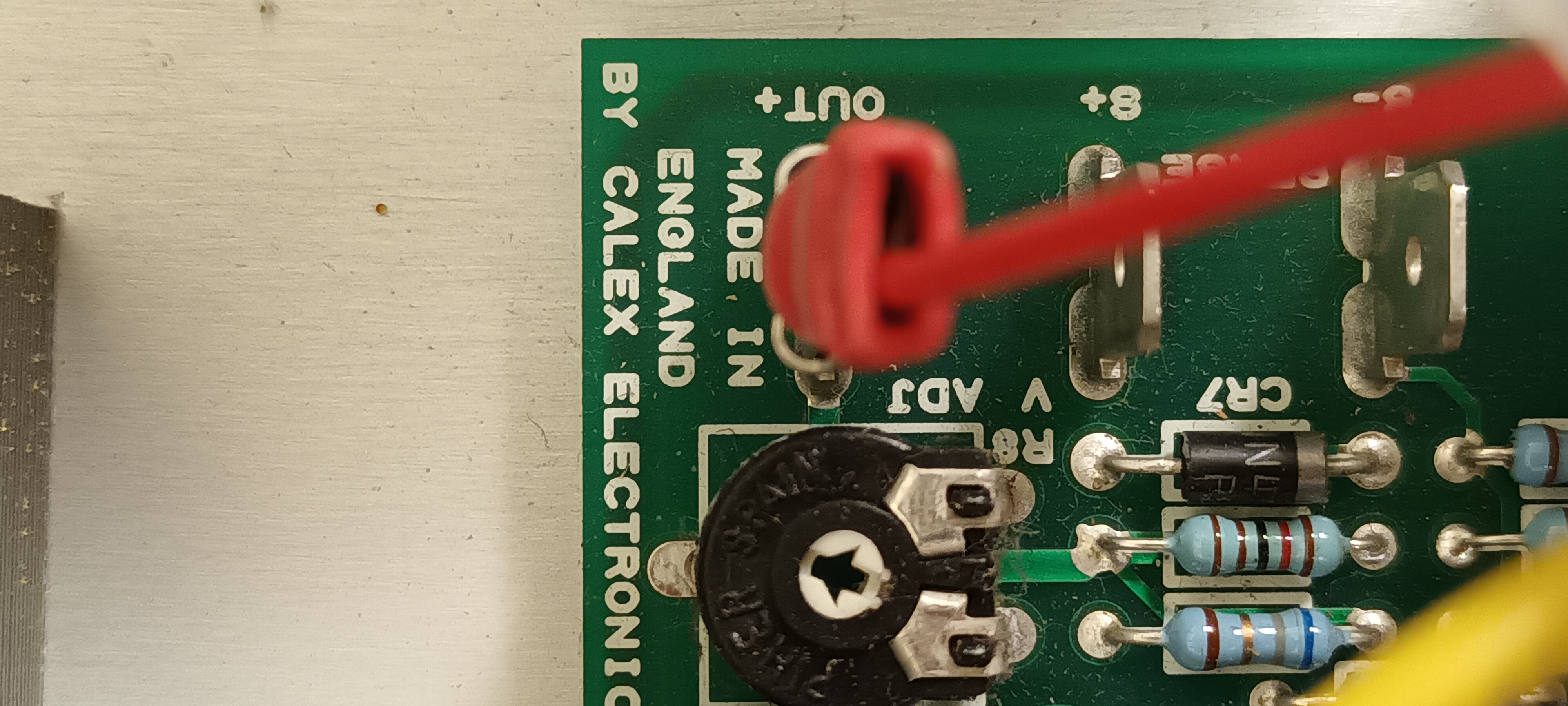
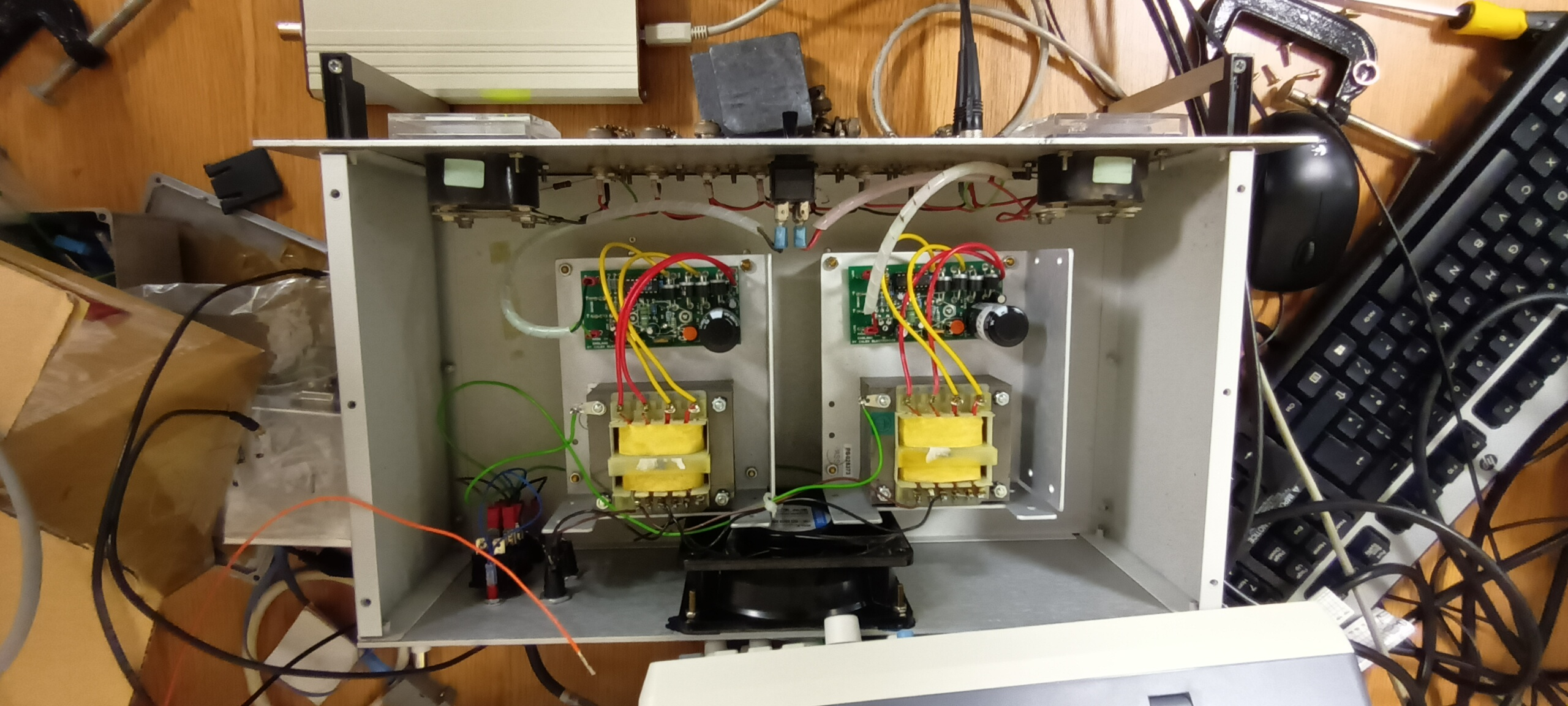
Setup and PSU details - attachments 1-3

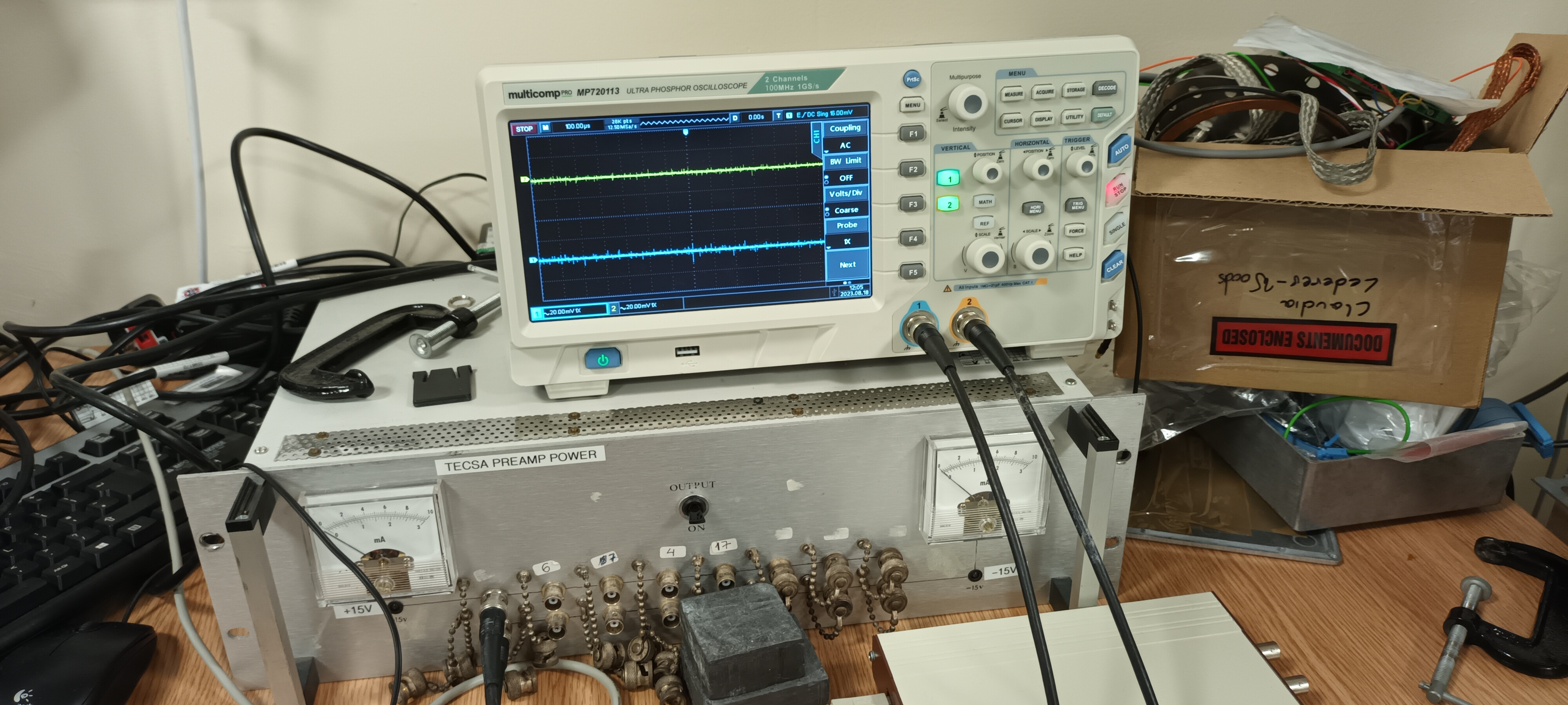
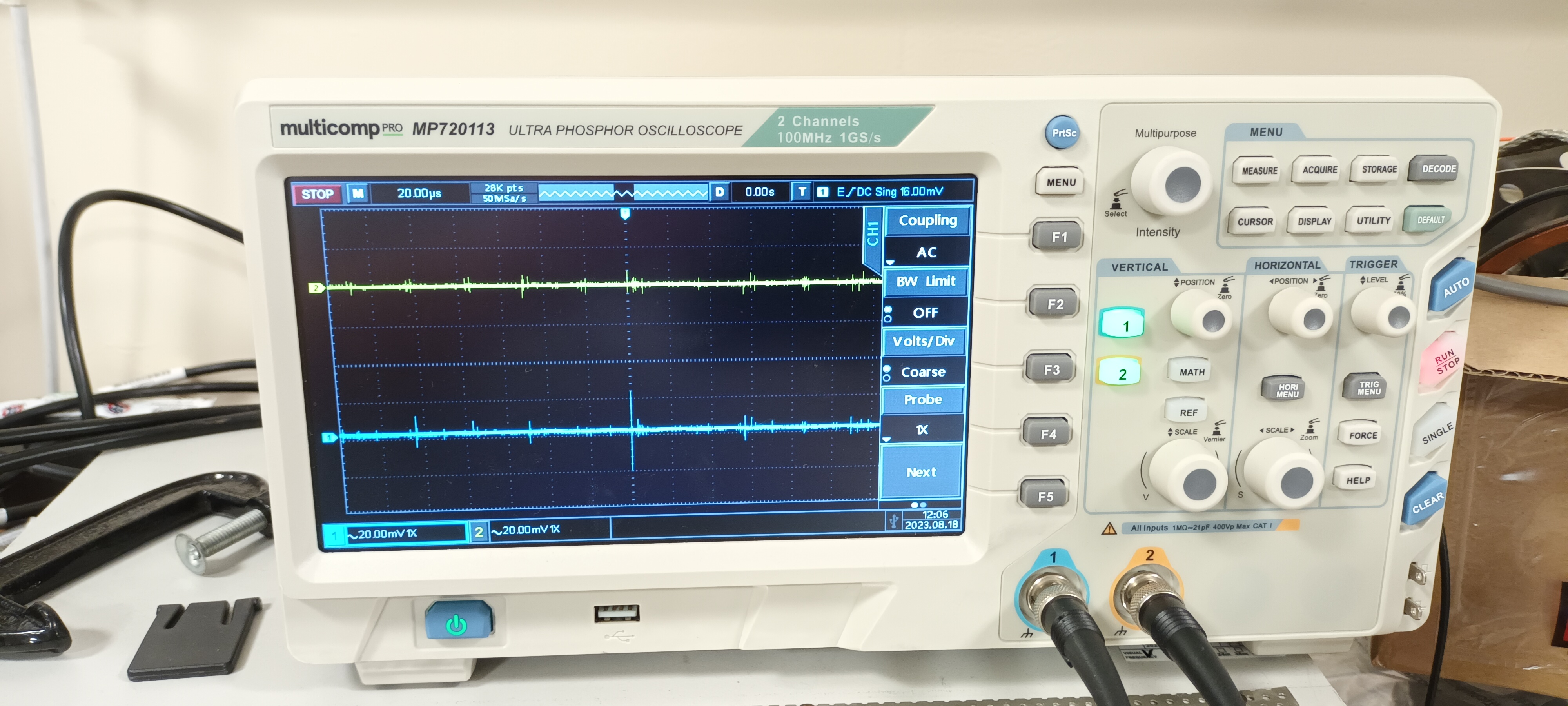
DSO ch#1 +15V AC/1M, ch#2 -15V AC/1M - y: 20mV/div x: 100ns, 200ns, 1us, 2us, 10us, 20us & 100us/div - attachments 4-10 |
| Attachment 1: 20230818_115256.jpg
|
|
| Attachment 2: 20230818_120358.jpg
|
|
| Attachment 3: 20230818_120127.jpg
|
|
| Attachment 4: 20230818_115311.jpg
|
|
| Attachment 5: 20230818_115329.jpg
|
|
| Attachment 6: 20230818_115250.jpg
|
|
| Attachment 7: 20230818_115421.jpg
|
|
| Attachment 8: 20230818_115341.jpg
|
|
| Attachment 9: 20230818_115409.jpg
|
|
| Attachment 10: 20230818_115352.jpg
|
|
|
67
|
Mon Aug 21 12:08:59 2023 |
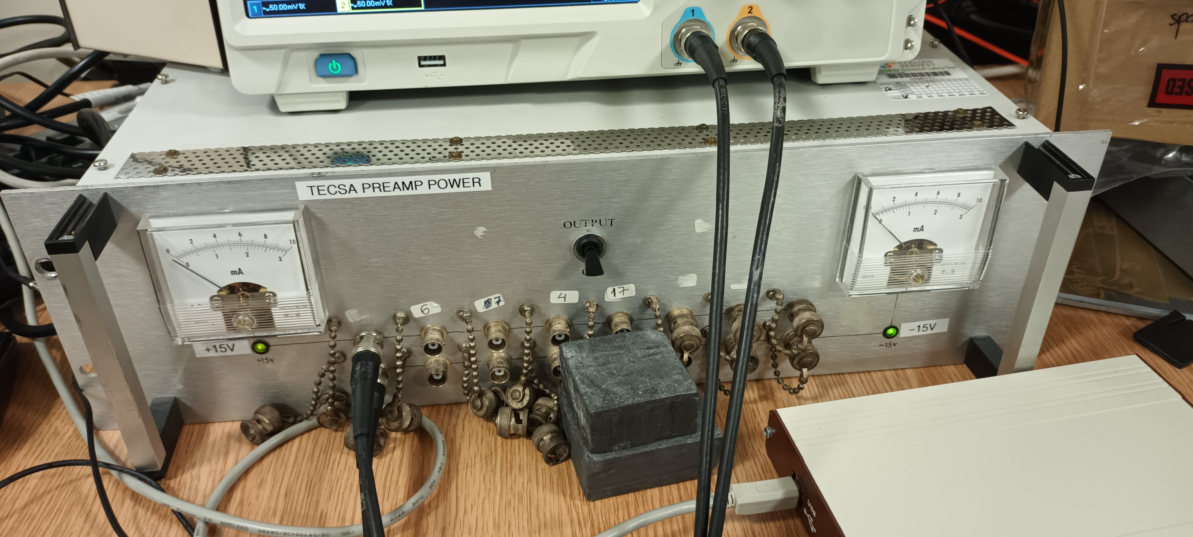
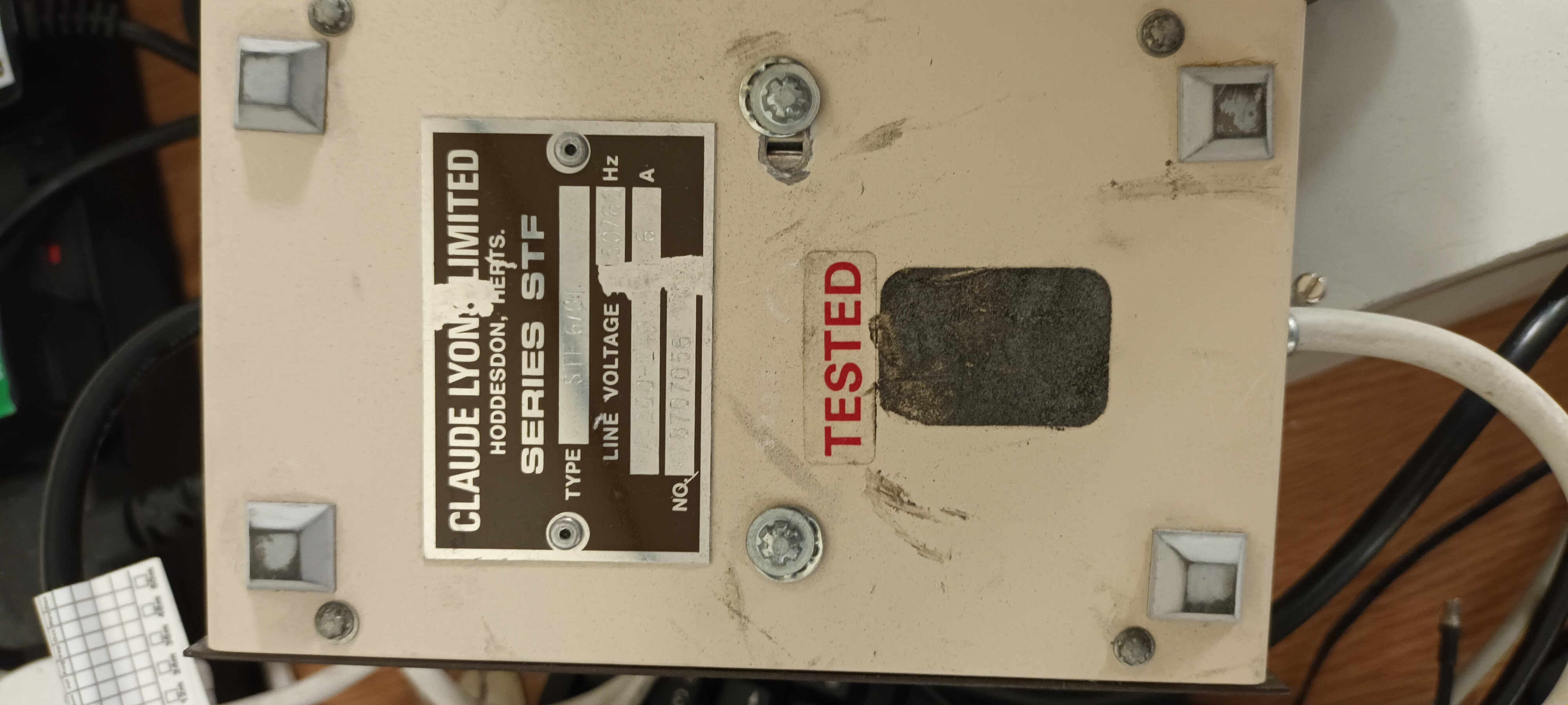
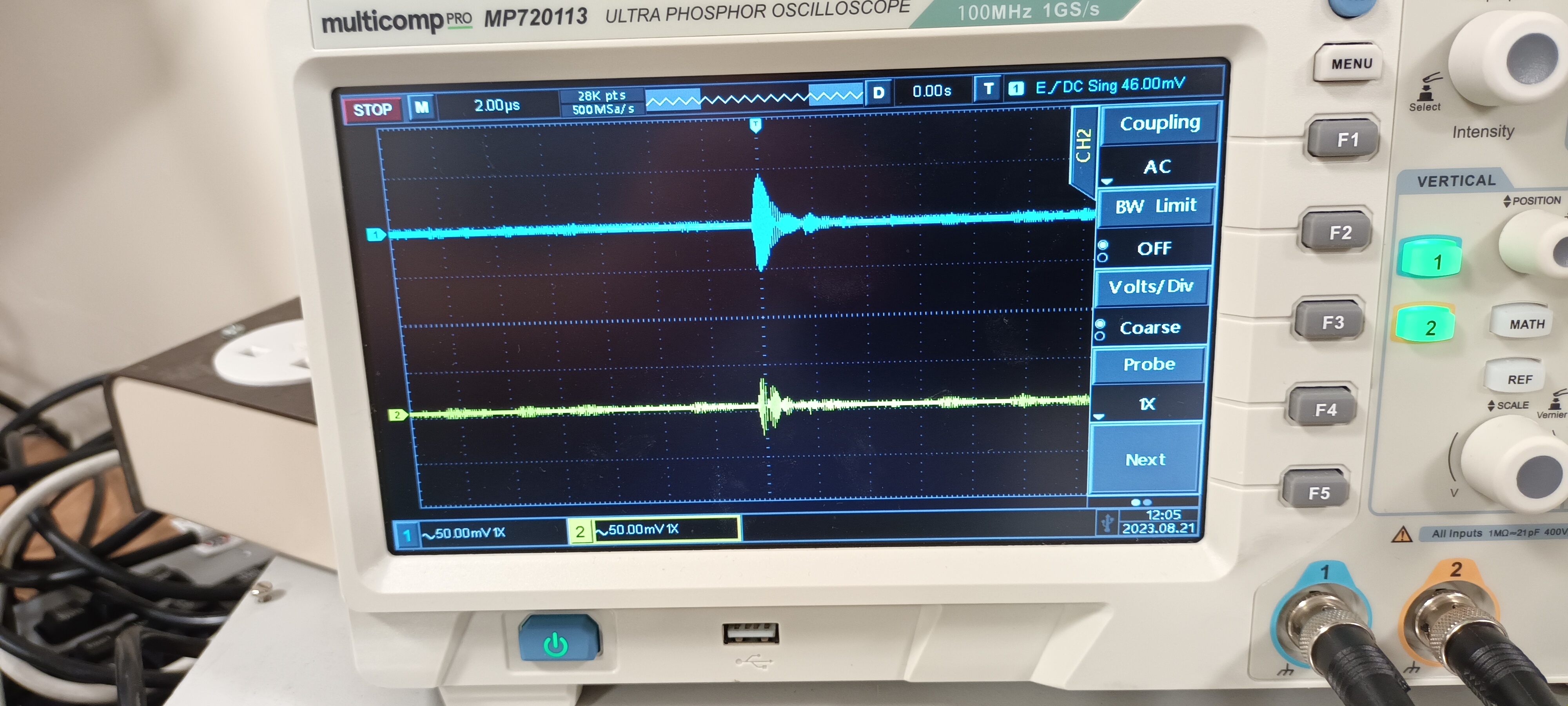
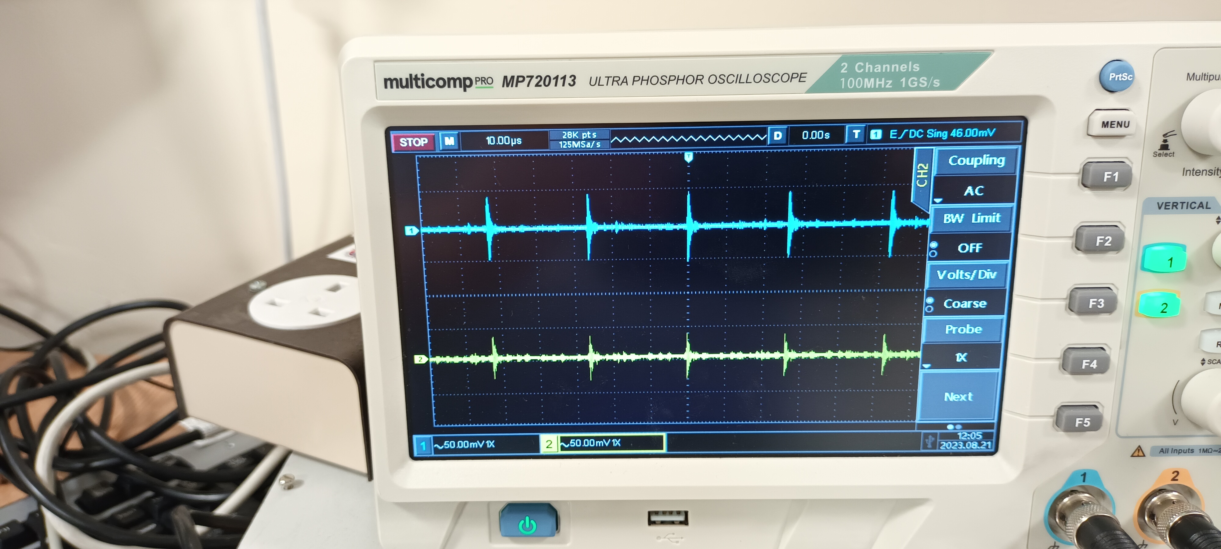
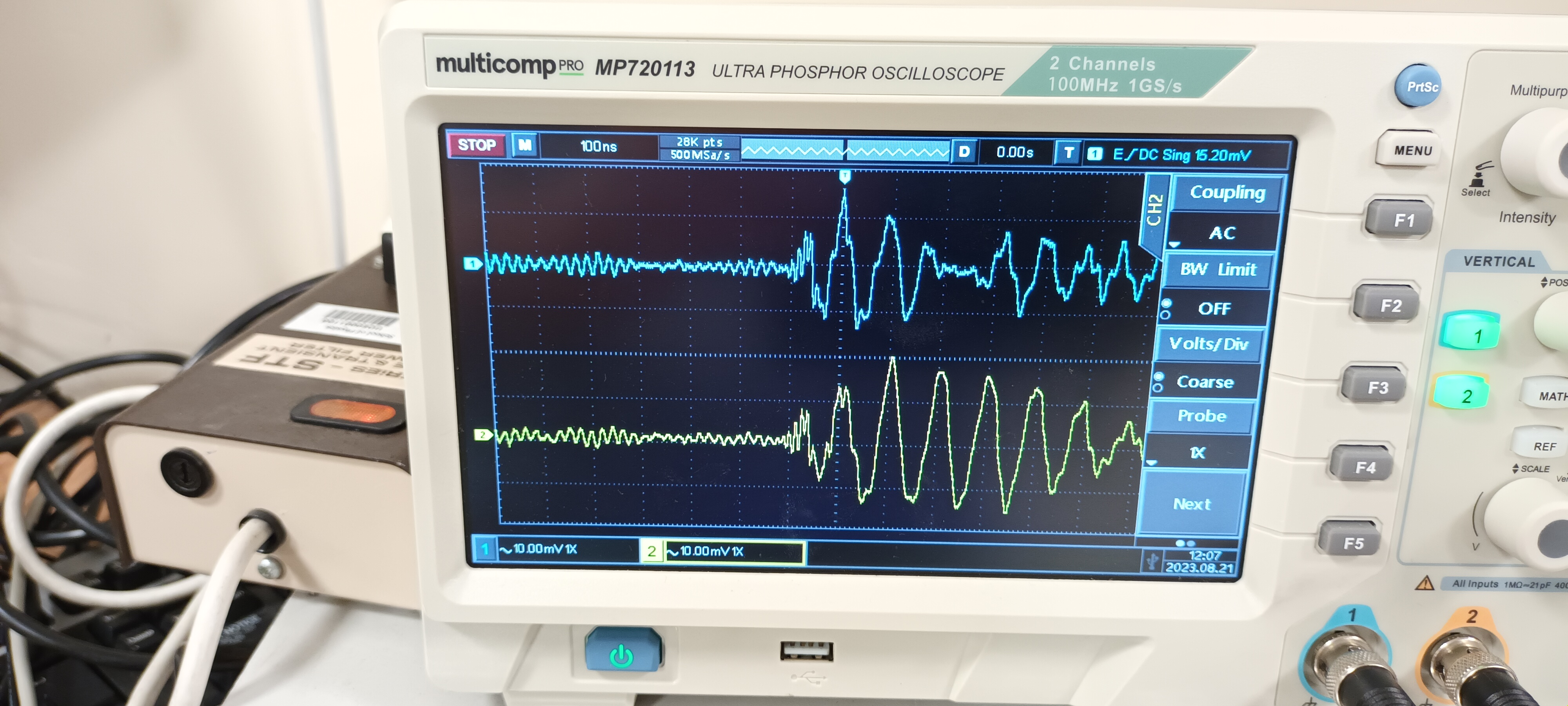
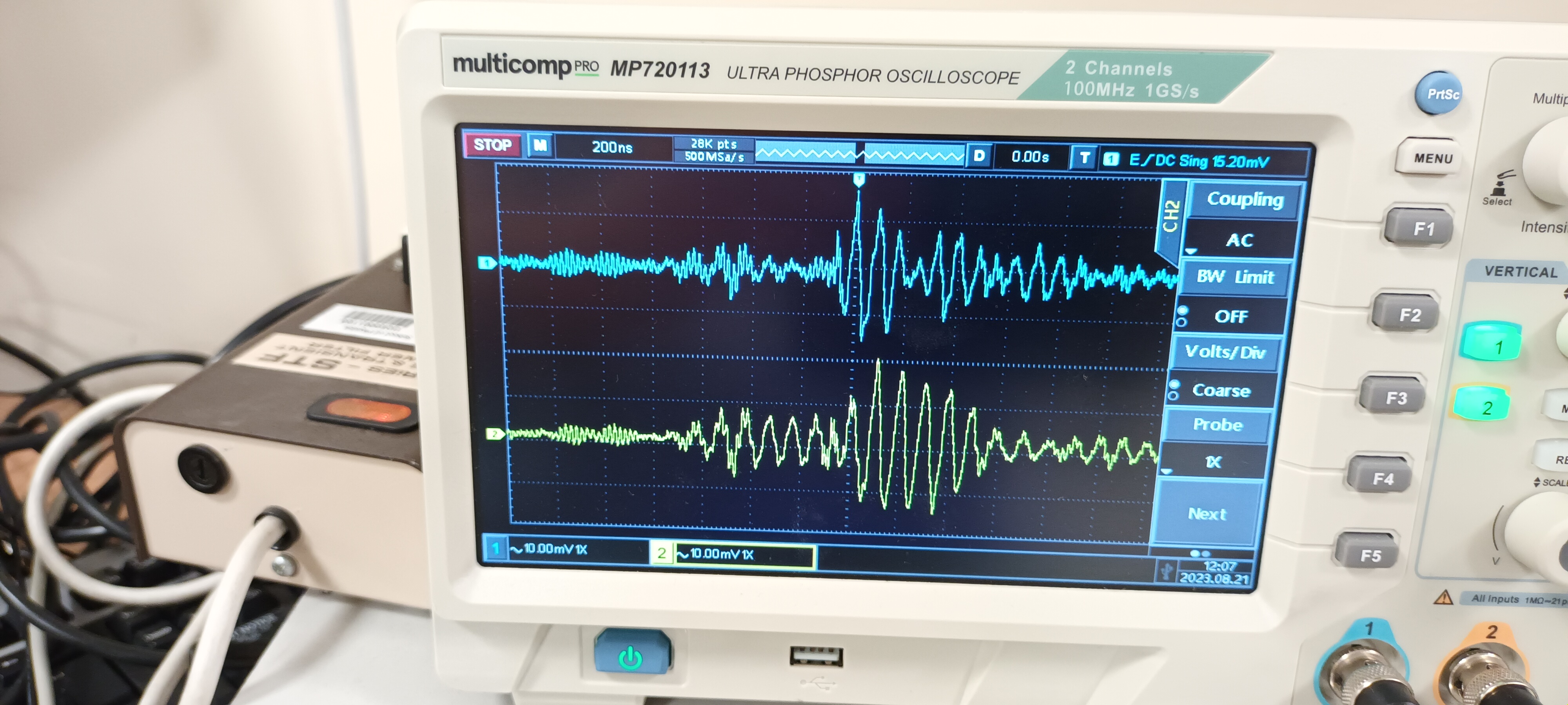
TD | RAL108 +/-15V PSU test - JCMB 21.8.23 |
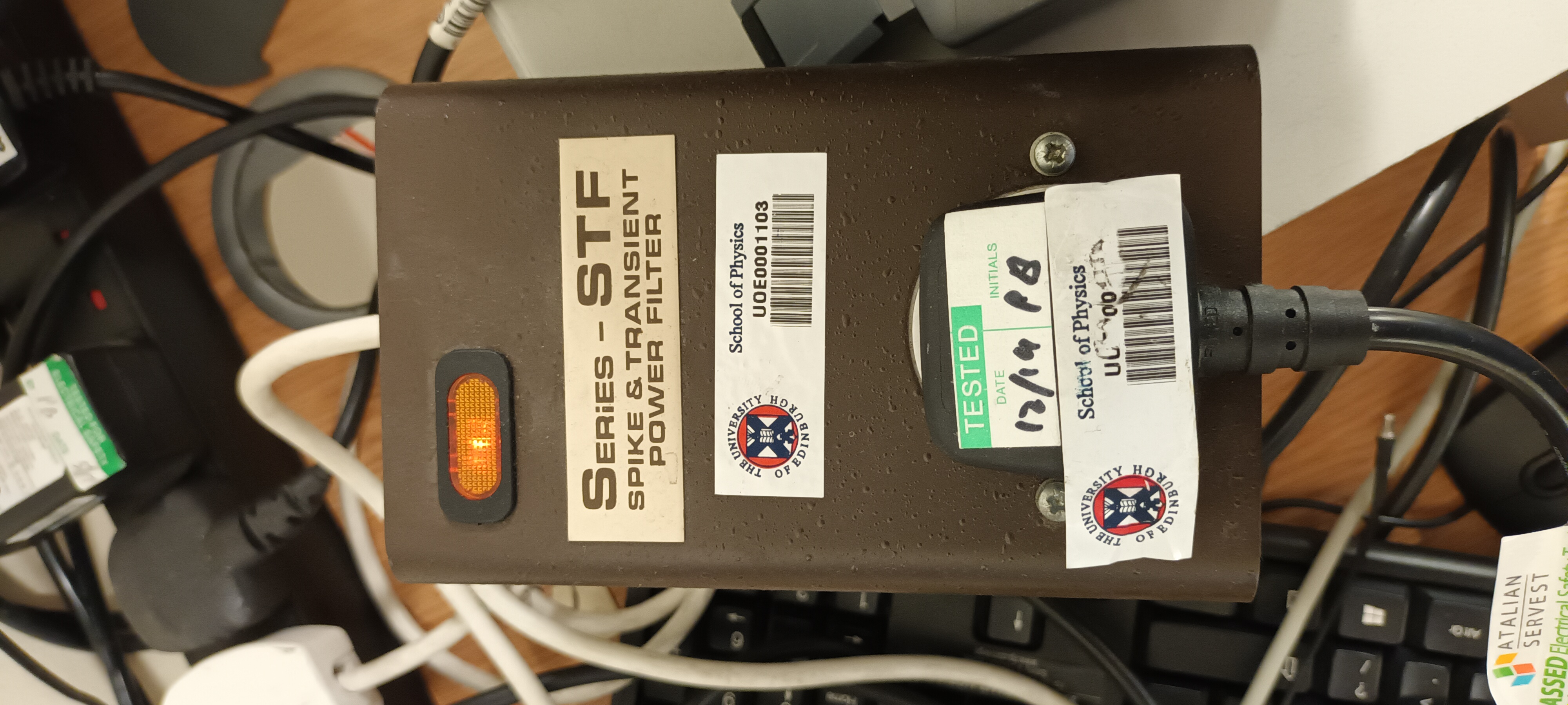
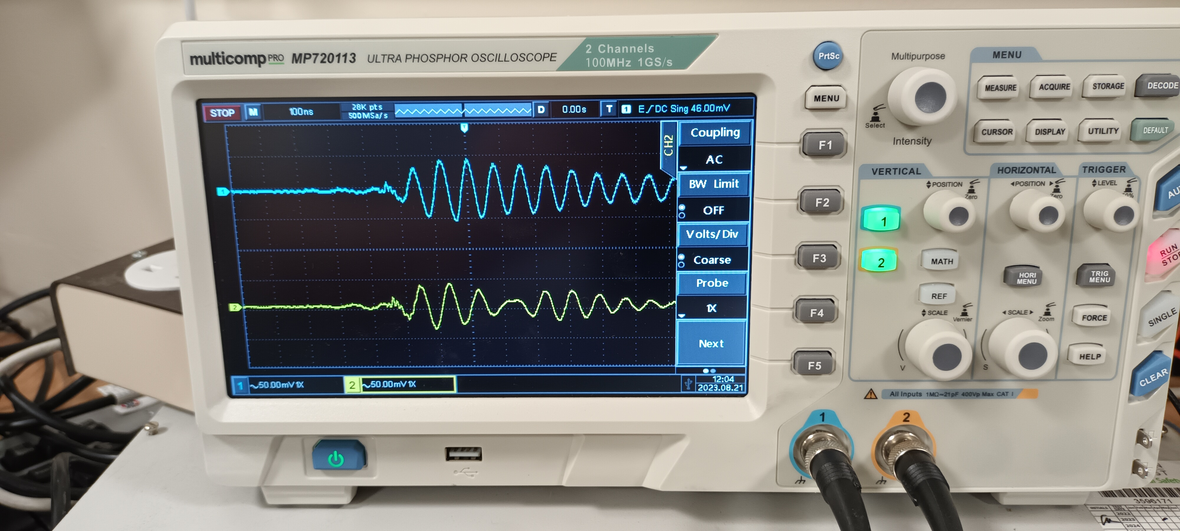
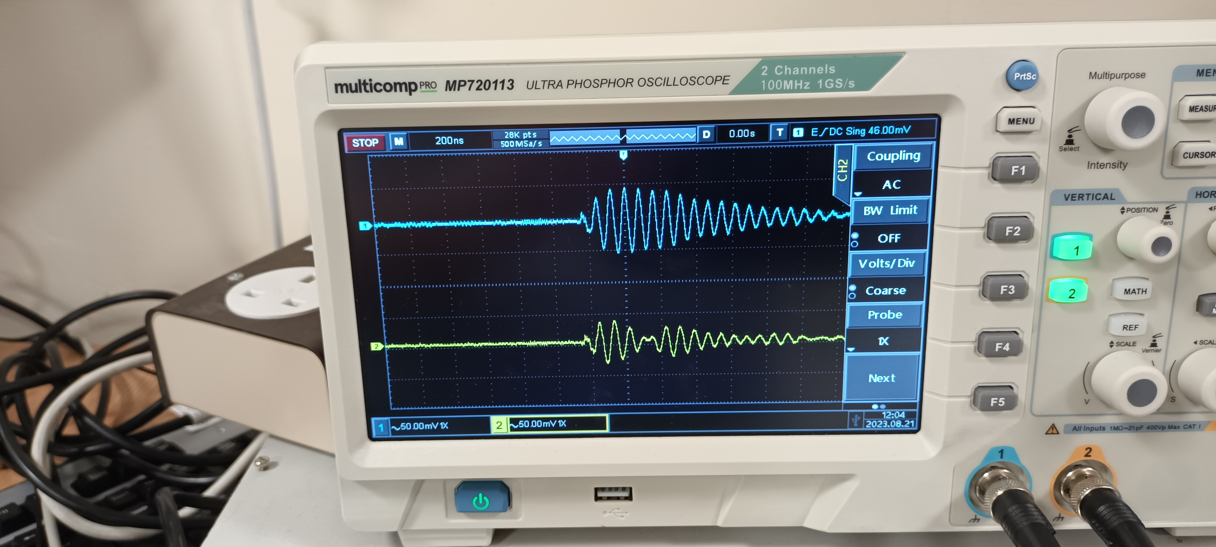
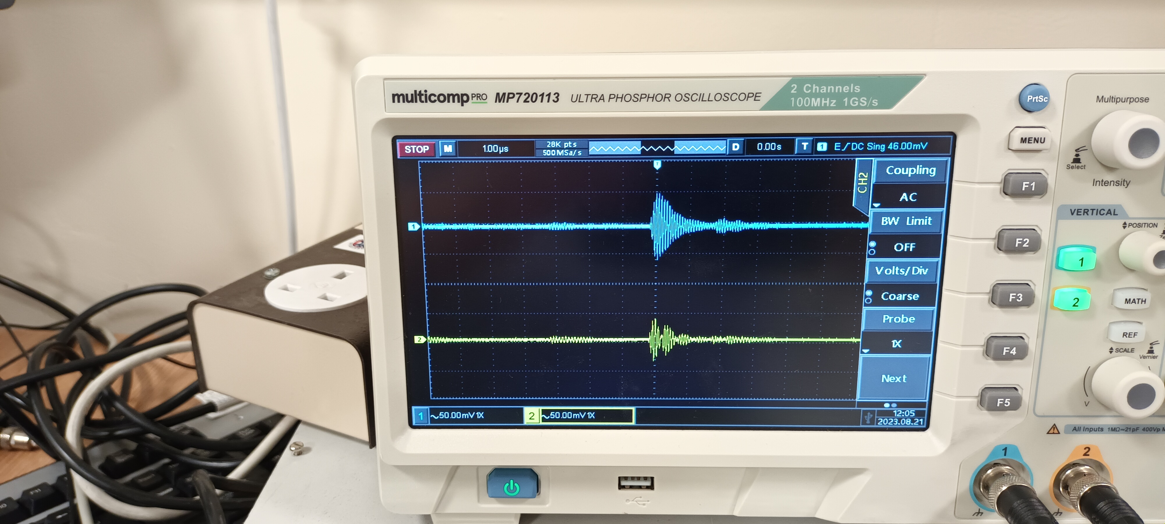
PSU Calex

Setup, PSU and ac mains filter - attachments 1-3


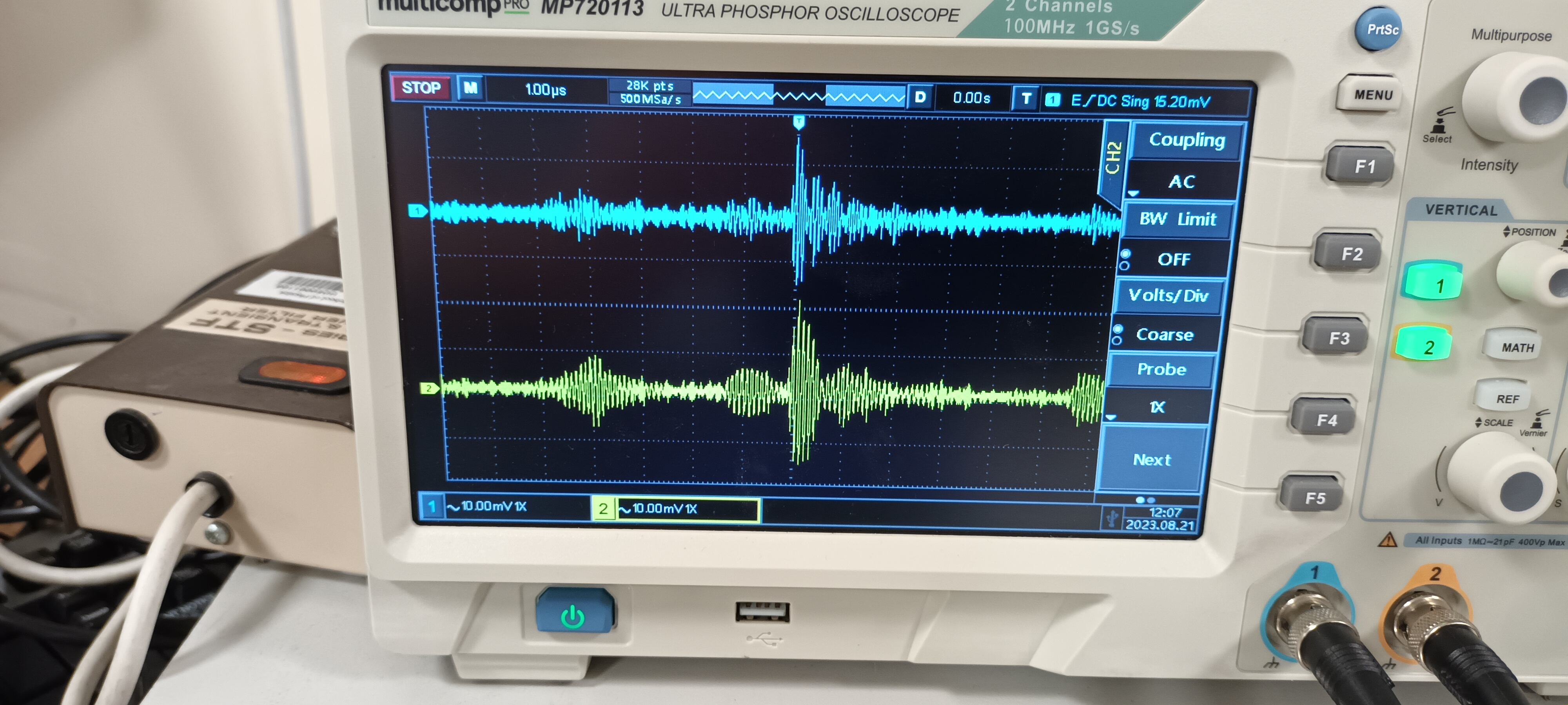
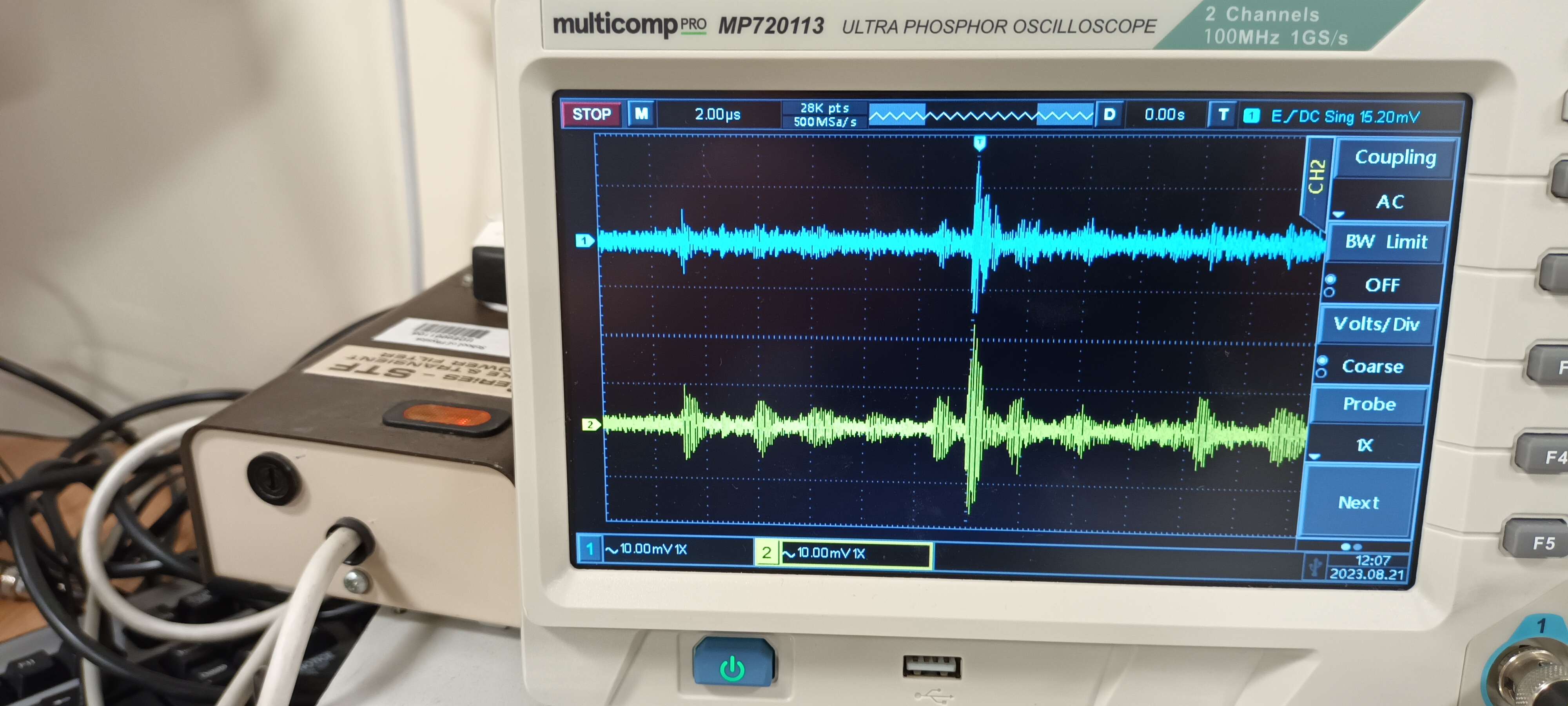
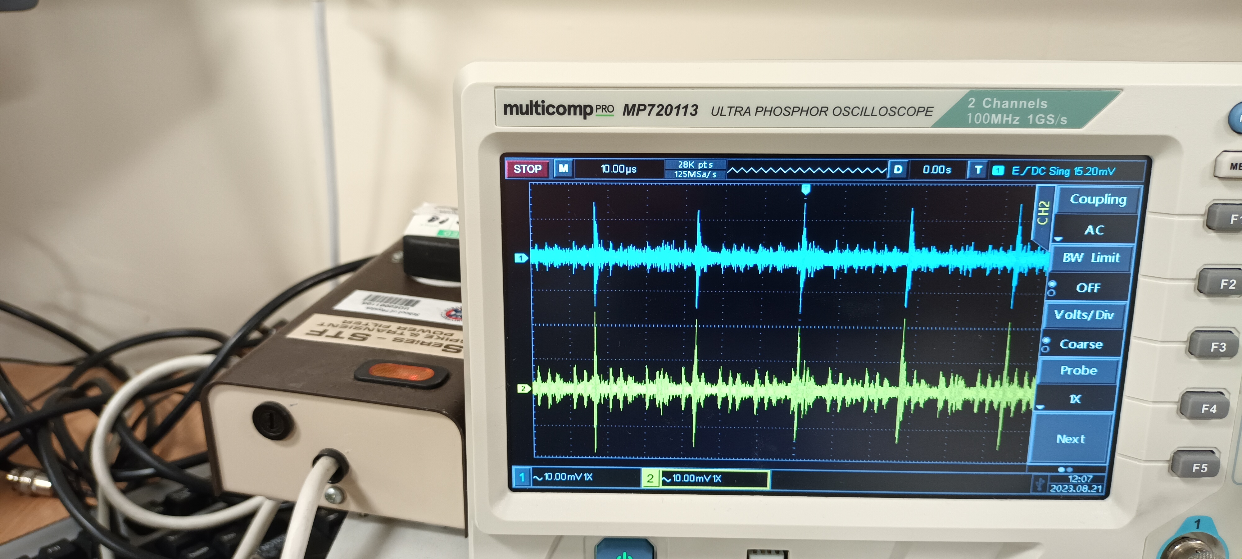
DSO ch#1 +15V AC/1M, ch#2 -15V AC/1M - y: 50mV/div x: 100ns, 200ns, 1us, 2us, 10us/div

Without ac mains filter - attachments 4-8


DSO ch#1 +15V AC/1M, ch#2 -15V AC/1M - y: 10mV/div x: 100ns, 200ns, 1us, 2us, 10us/div

With ac mains filter - attachments 9-13

Conclusion - Claud Lyons Ltd STF Series Surge & Transient Power Filter produces c. x 2 attenuation of HF noise transients |
| Attachment 1: 20230821_115139.jpg
|
|
| Attachment 2: 20230821_115314.jpg
|
|
| Attachment 3: 20230821_115259.jpg
|
|
| Attachment 4: 20230821_115144.jpg
|
|
| Attachment 5: 20230821_115156.jpg
|
|
| Attachment 6: 20230821_115206.jpg
|
|
| Attachment 7: 20230821_115216.jpg
|
|
| Attachment 8: 20230821_115229.jpg
|
|
| Attachment 9: 20230821_115415.jpg
|
|
| Attachment 10: 20230821_115424.jpg
|
|
| Attachment 11: 20230821_115438.jpg
|
|
| Attachment 12: 20230821_115447.jpg
|
|
| Attachment 13: 20230821_115457.jpg
|
|
|
79
|
Sat Sep 14 09:30:40 2024 |
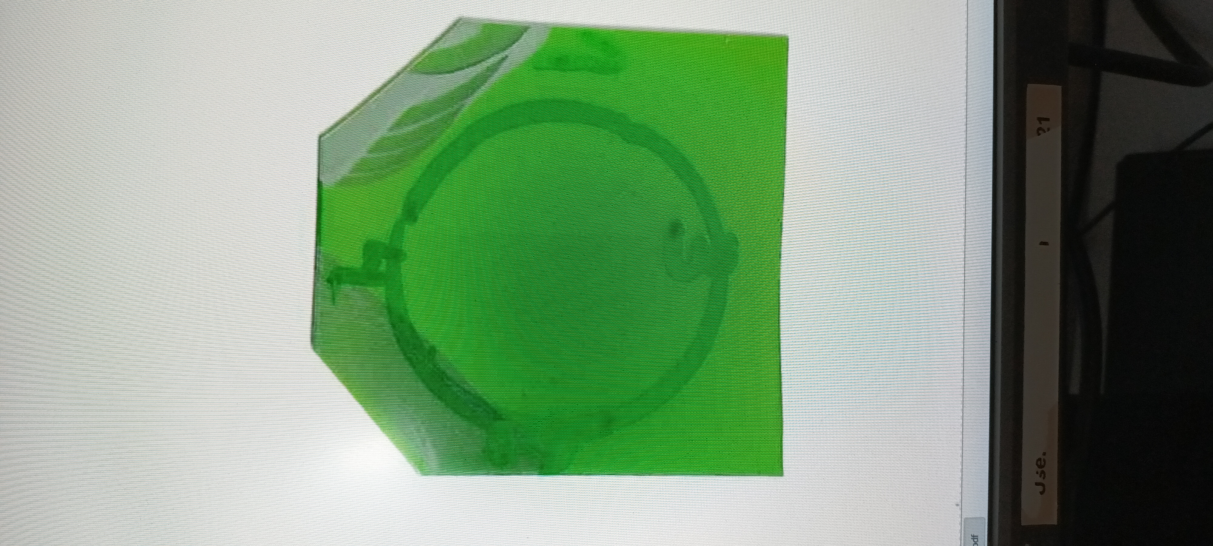
TD | Neutron beam profile |
Neutron beam profile - film exposure overnight 12/13.9.24 |
| Attachment 1: 20240914_101751.jpg
|
|
|
80
|
Mon Sep 16 12:36:45 2024 |
TD | 34-way IDC to 37-way D connector ribbon cables |
The 2x sets of 34-way IDC to 37-way D connctor ribbon cables used at GSI for the two-alpha decay measurement have been located - see attachments 1-4.

They have been packed for shipment to CERN and delivered to stores for shipment. Awaiting quotation and P&M PO. |
| Attachment 1: 20240916_121057_(1).jpg
|
.jpg.png)
|
| Attachment 2: 20240916_121052_(1).jpg
|
.jpg.png)
|
| Attachment 3: 20240916_121047_(1).jpg
|
.jpg.png)
|
| Attachment 4: 20240916_121003_(1).jpg
|
.jpg.png)
|
|
85
|
Fri Jul 11 09:16:18 2025 |
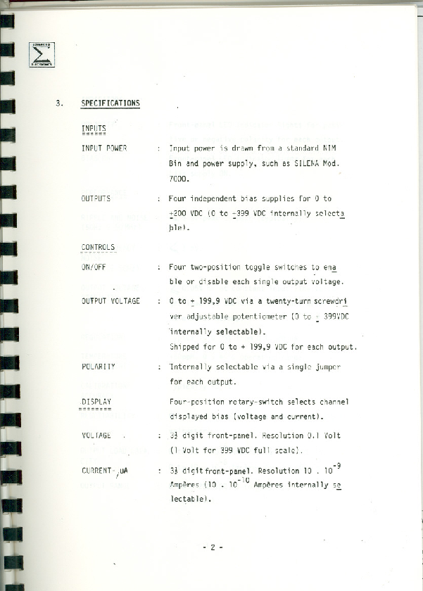
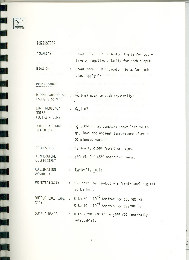
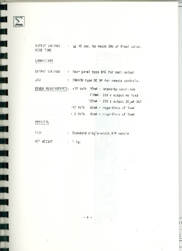
TD | Silena 7710 Quad Bias Supply manual and internal configuration |
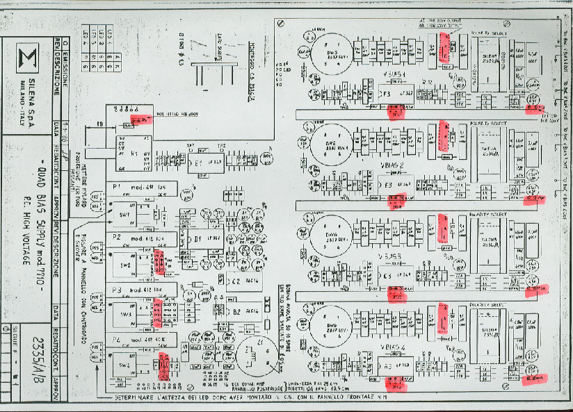
Manual - see attachment 1


Internal configuration

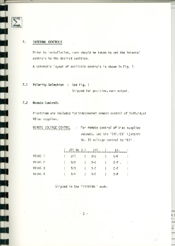
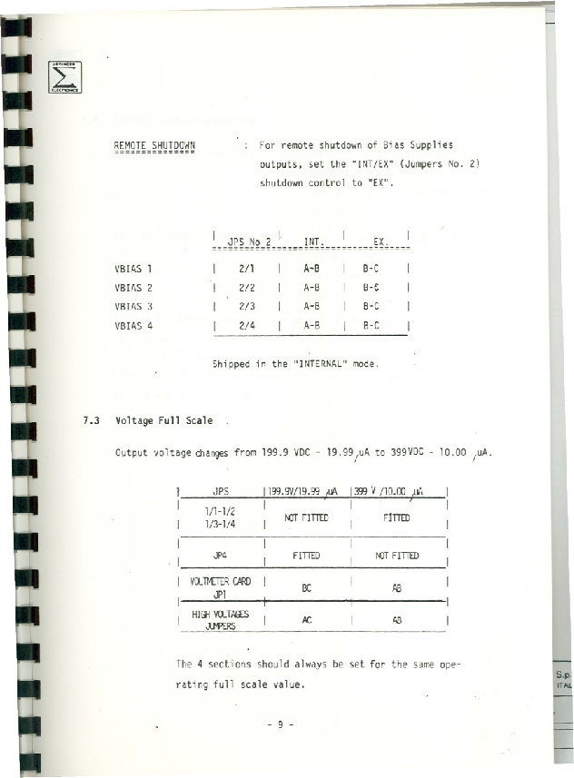
Voltage full scale - 400V/10uA

JP1/1-4 fitted
JP4 fitted *see note below
DVM card JP1 AB
HV jumpers AB

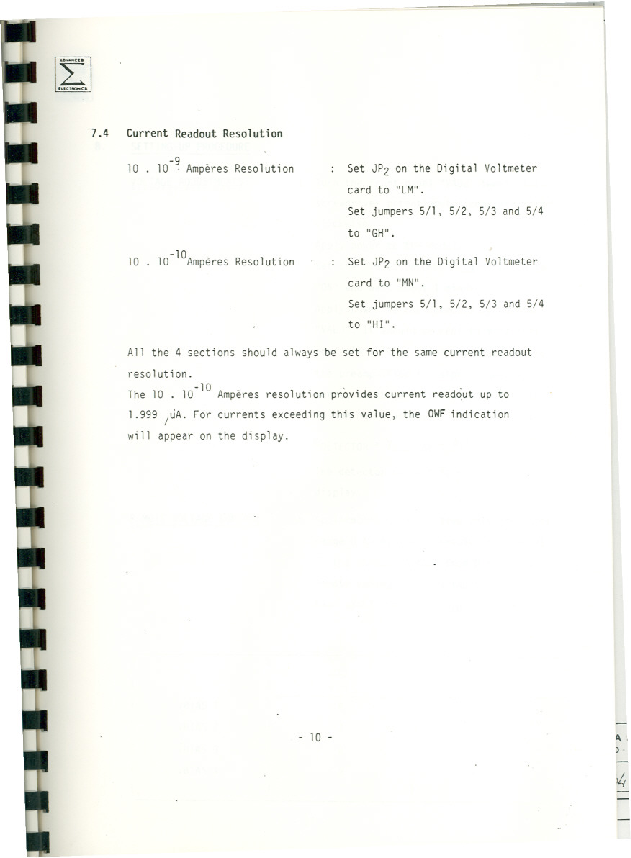
Current readout resolution - 10nA

DVM card JP2 LM
JP5/1-5 GH


Polarity - channels 1-4 negative

Note with channel 1 voltage set to -180V the output voltage measured by DMM is -40V.
The output impedance of the Silena 7710 outputs may be comparable to the input impedance of the DMM (DMM typically c. 20-40M) so the measured voltage will be a *lower*
limit.

With JP4 removed (per manual instructions for voltage full scale 400V/10uA) the front panel reads -20V with an output voltage measured by DMM of -40V.
Again, the measured voltage will be a lower limit.

By observation of the behaviour of the electronic noise of p+n junction and n+n Ohmic strips as a function of bias for MSL type W1 DSSSD 3353-4 (75um) the voltage
applied to the DSSSD is > depletion.
MSL QA tests report depletion voltage 28V and test/operating voltage 28+10V = 38V. |
| Attachment 1: Silena_7710_quad_bias_supply.pdf
|
|
|
87
|
Sat Jul 12 11:25:35 2025 |
Selin | The Detector Bias-Leakage Current Data |
This Excel sheet has the detector bias-leakage current data and plot for both detectors.
Detector 2 has lower leakage current and a flatter plateau region. |
| Attachment 1: Ca-VoltageCurrent.xlsx
|
|
88
|
Sat Jul 12 11:34:31 2025 |
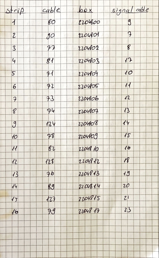
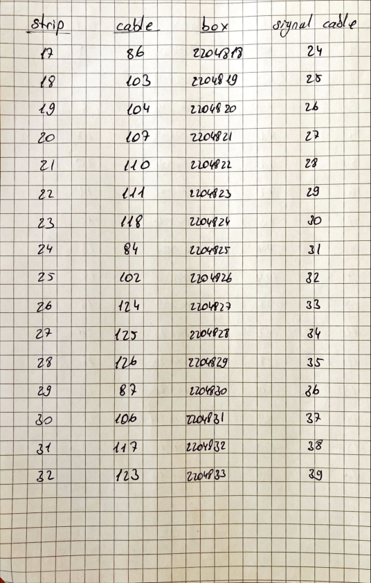
Selin | Detector-Cable Connections |
List of the detectors and the connections. |
| Attachment 1: Detector-Cable.pdf
|
|
|
89
|
Wed Jul 16 08:51:06 2025 |
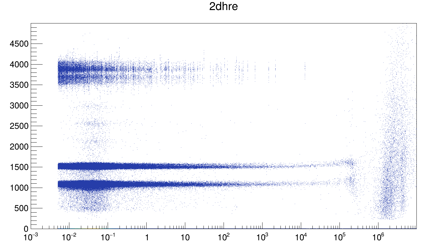
Selin | Run221136 Lithium Uncalibrated Data |
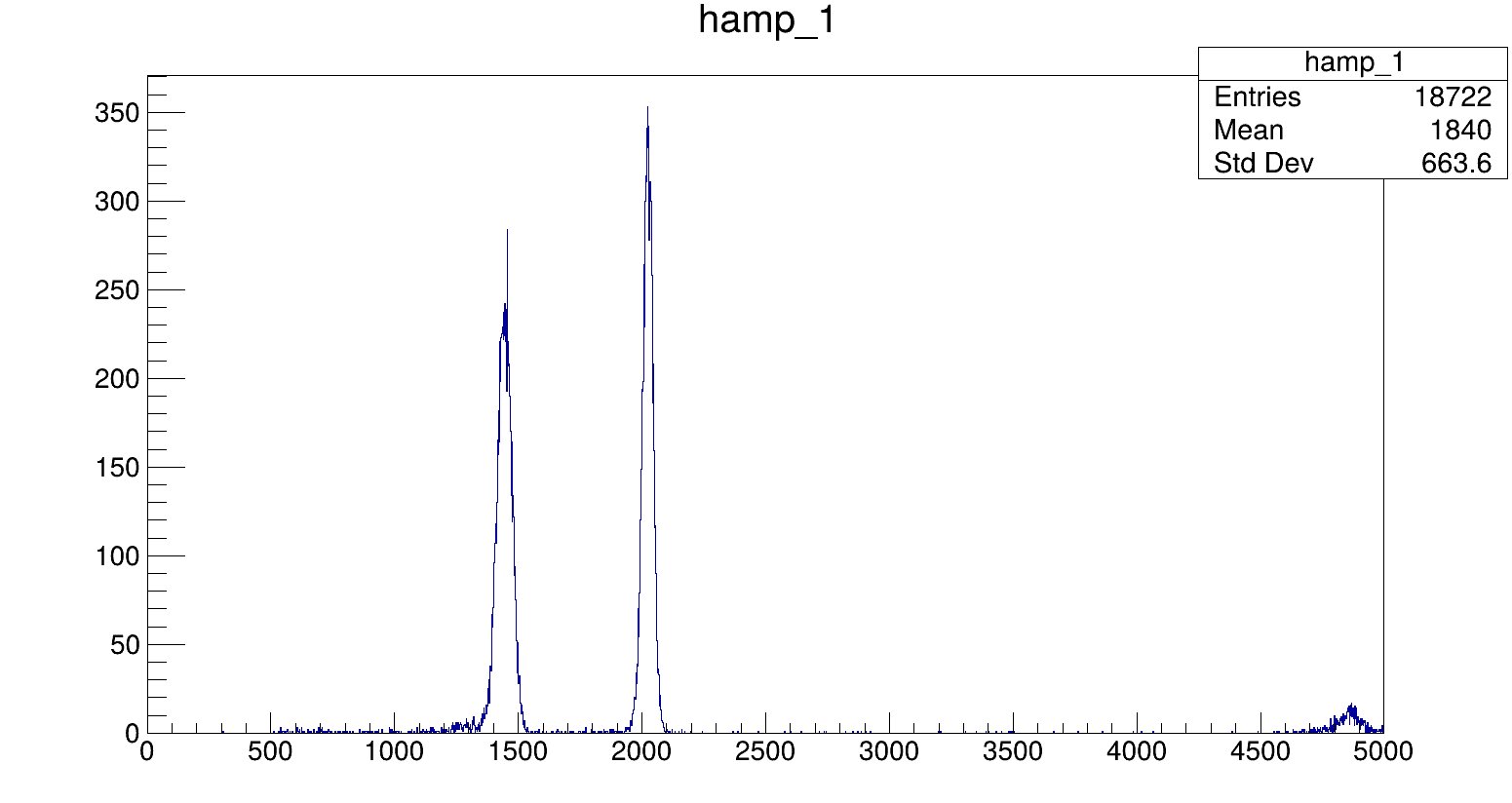
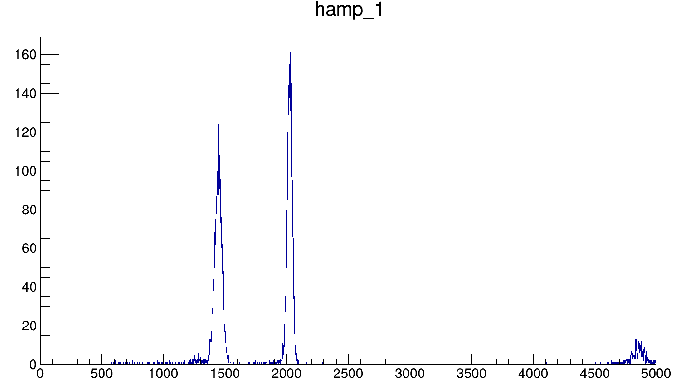
Plots of Lithium #3 run (221136) from the Ca41 campaign with the right voltage applied (11.07.2025).
1- Uncalibrated amplitude spectra of strip 1 (dedicated).
2- Uncalibrated amplitude spectra of strip 1 (parasitic).
3- Uncalibrated 2d energy plot of Lithium dedicated data. |
| Attachment 1: Li_Strip1.png
|
|
| Attachment 2: Li_Strip1_Par.png
|
|
| Attachment 3: Li_ded_2d.png
|
|
|
90
|
Wed Jul 16 08:55:22 2025 |
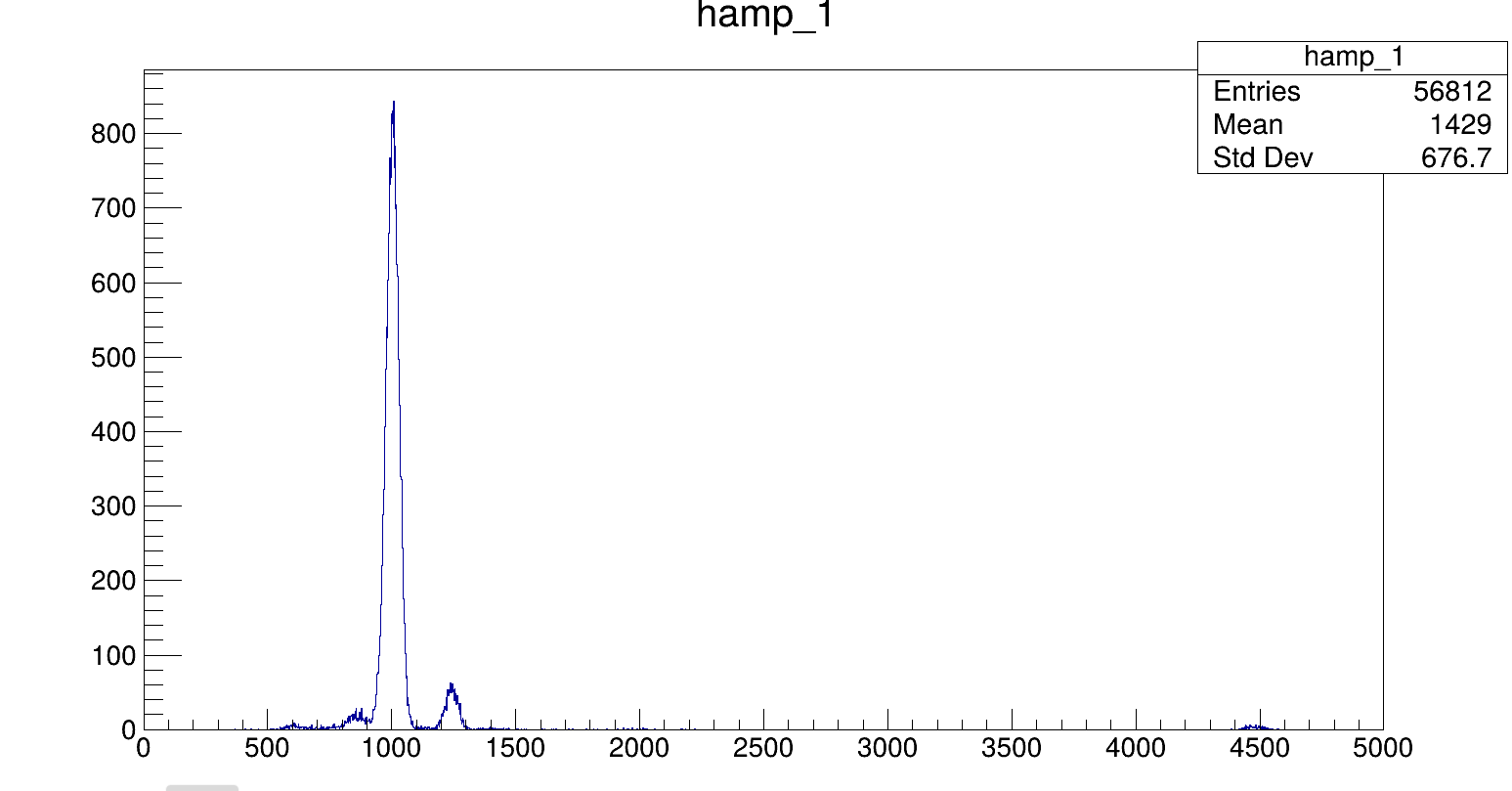
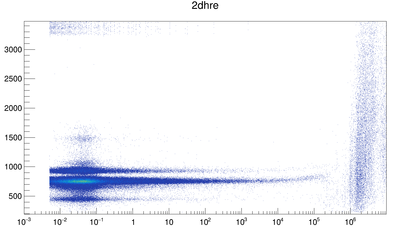
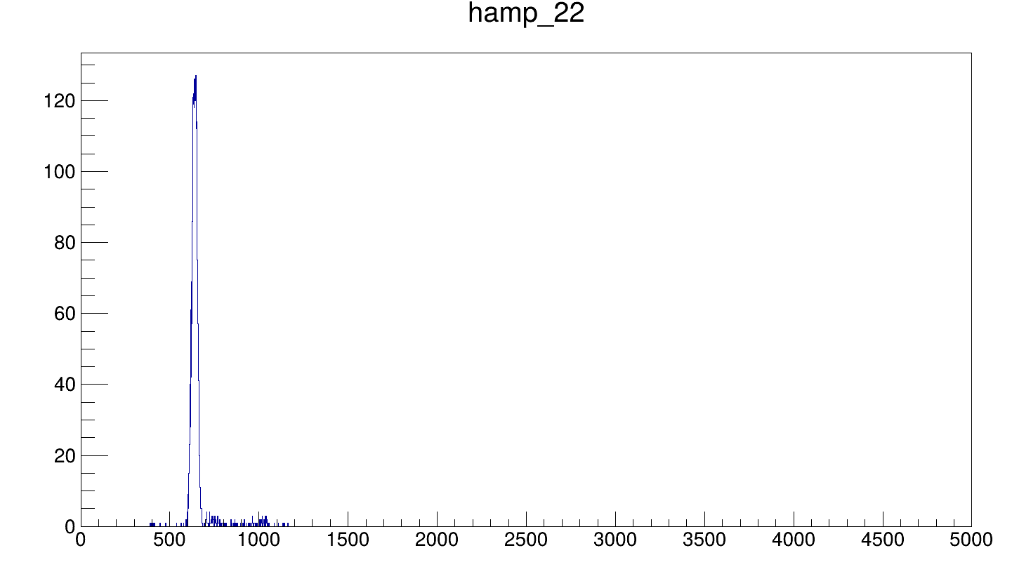
Selin | Run221141 Boron Uncalibrated Data |
Plots of Boron #1 run (221141) from the Ca41 campaign with the right voltage applied (11.07.2025).
1- Uncalibrated amplitude spectra of strip 1 (dedicated).
2- Uncalibrated 2d energy plot of Boron dedicated data.
3- Uncalibrated amplitude spectra of strip 22 (dedicated). The alpha-0 on the back strips has lower counts. |
| Attachment 1: B_Strip1.png
|
|
| Attachment 2: B_ded_2d.png
|
|
| Attachment 3: B_Strip22.png
|
|
|
92
|
Wed Jul 16 11:45:39 2025 |
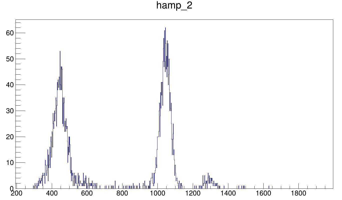
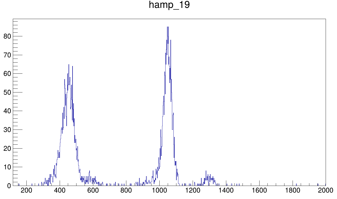
Selin | Boron Spectra Update After Setting Change + Pulser Removed |
Uncalibrated amplitude spectra of Boron (run221188) after the settings were changed, the pulser was removed, and the threshold in the UserInput has been lowered. Both alphas can be seen in the front and back strips. The ratios between the alphas are similar for front (0.066) and back (0.063) strips.
1- Uncalibrated amplitude spectra of strip 2.
2- 1- Uncalibrated amplitude spectra of strip 19. |
| Attachment 1: B_Strip2_ded.png
|
|
| Attachment 2: B_Strip19_ded.png
|
|
|
95
|
Mon Jul 21 10:30:01 2025 |
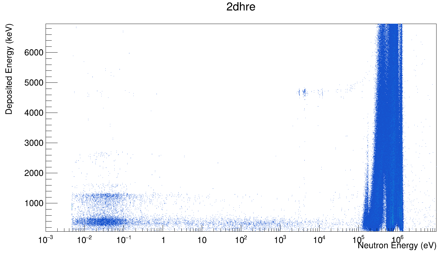
Selin | The 2D Energy Spectrum of Ca41 |
The 2D energy spectrum of Ca41 (36 runs). The expected alpha energies are 4.8 MeV (alpha_0) and 2.7 MeV (alpha_1). |
| Attachment 1: Screenshot_from_2025-07-21_08-51-09.png
|
|
|
96
|
Mon Aug 4 16:32:56 2025 |
Selin | Lithium Consistency Check |
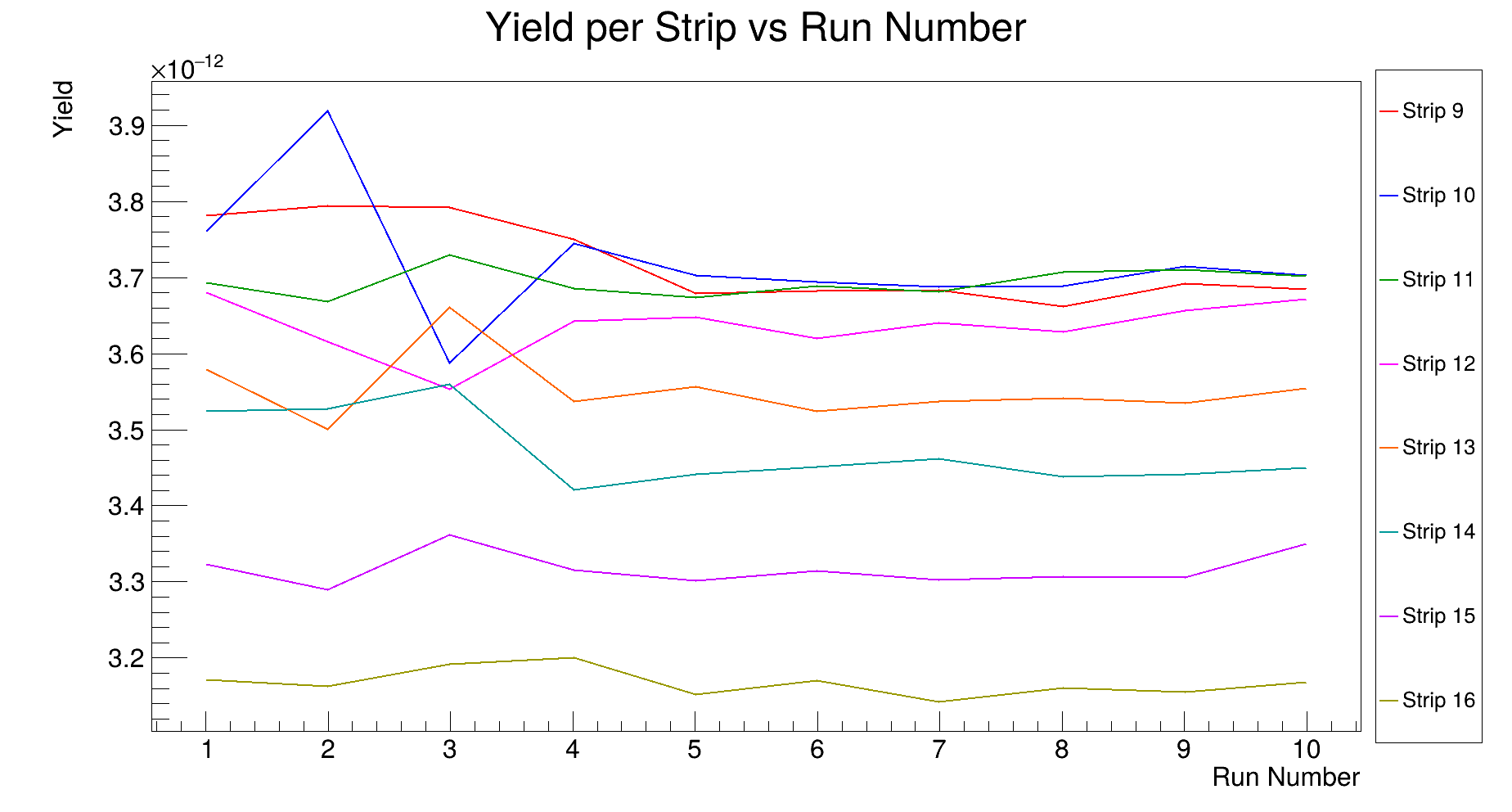
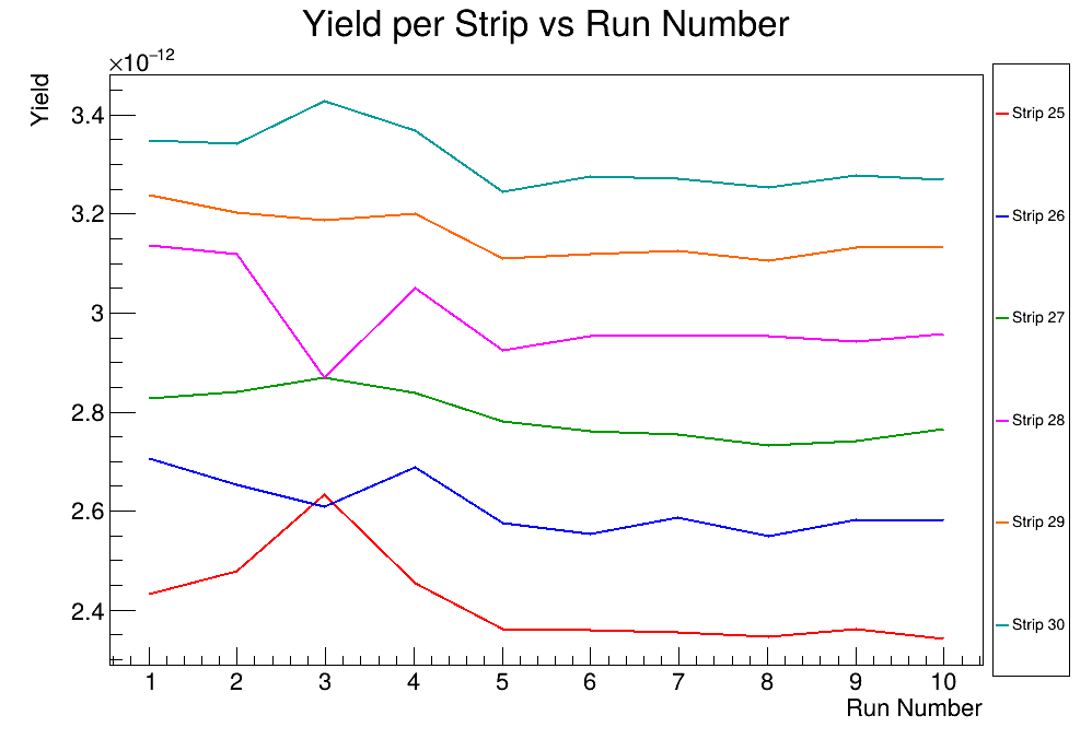
These are the consistency checks done for Lithium sample.
Please note that in the earlier runs, the cables 22 and 23 were switched. |
| Attachment 1: Li1-8.png
|

|
| Attachment 2: Li9-16.png
|
|
| Attachment 3: Li17-24.png
|

|
| Attachment 4: Li25-32.png
|
|
|
97
|
Mon Aug 4 16:44:06 2025 |
Selin | Boron-1 Consistency Check |
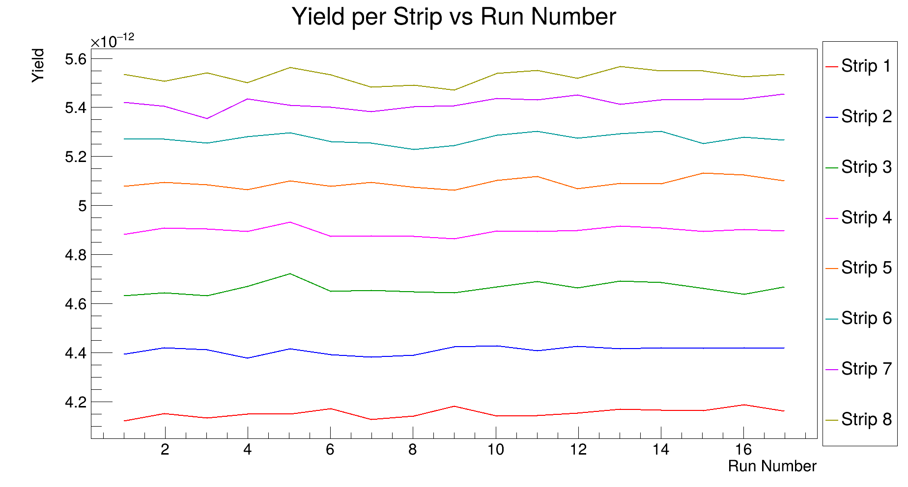
These are the consistency checks done for Boron-1 sample. |
| Attachment 1: B1-1-8.png
|
|
| Attachment 2: B1-9-16.png
|

|
| Attachment 3: B1-17-24.png
|

|
| Attachment 4: B1-25-32.png
|

|
|
98
|
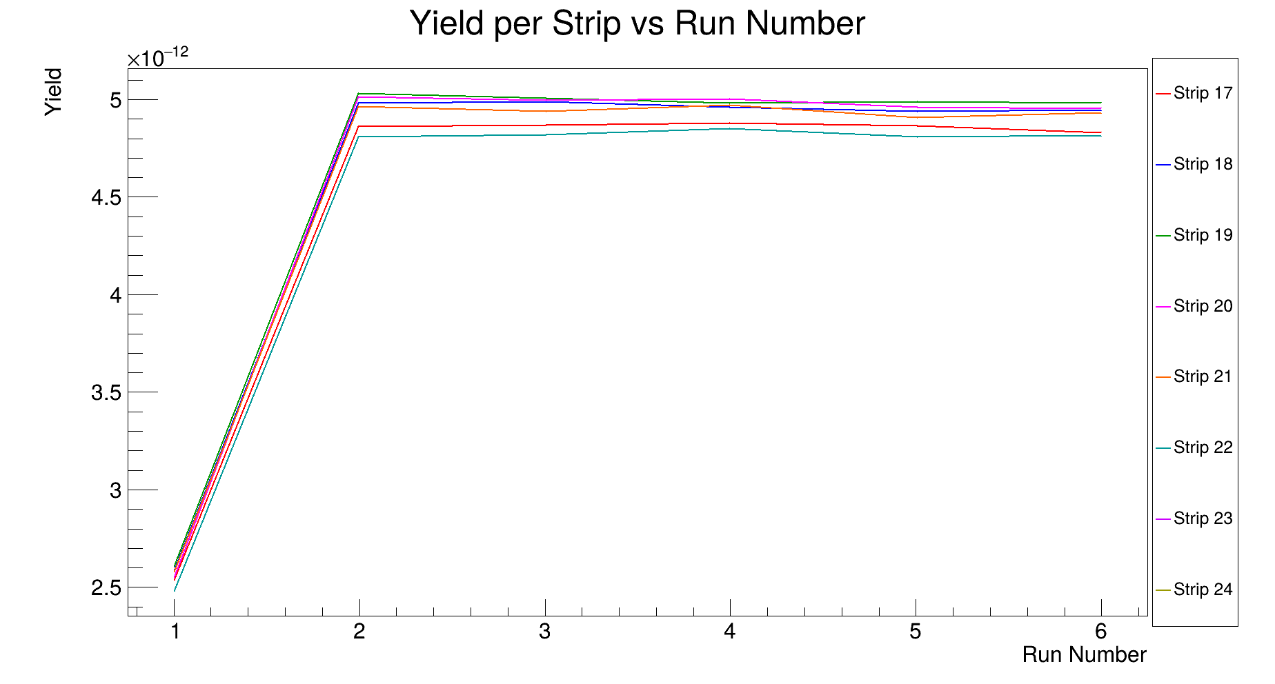
Mon Aug 4 16:45:43 2025 |
Selin | Boron-3 Consistency Check |
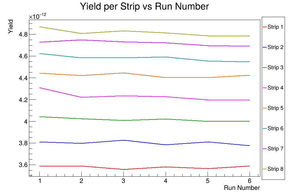
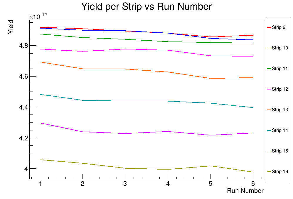
These are the consistency checks done for Boron-3 sample.
Please note that the back strips for the first run are mismatched due to the settings in DAQ. |
| Attachment 1: B3-1-8.png
|
|
| Attachment 2: B3-9-16.png
|
|
| Attachment 3: B3-17-24.png
|
|
| Attachment 4: B3-25-32.png
|

|