| ID |
Date |
Author |
Subject |
|
62
|
Mon Aug 14 11:00:13 2023 |
TD | RAL108 +/-15V PSU test in ISOLDE hall |
This morning 2x RAL108 +/-15V PSUs were borrowed from the Edinburgh equipment in the ISOLDE hall to check whether the same transient noise is observed at the +/-15V PSU
outputs - this was confirmed. See https://elog.ph.ed.ac.uk/nToF/63

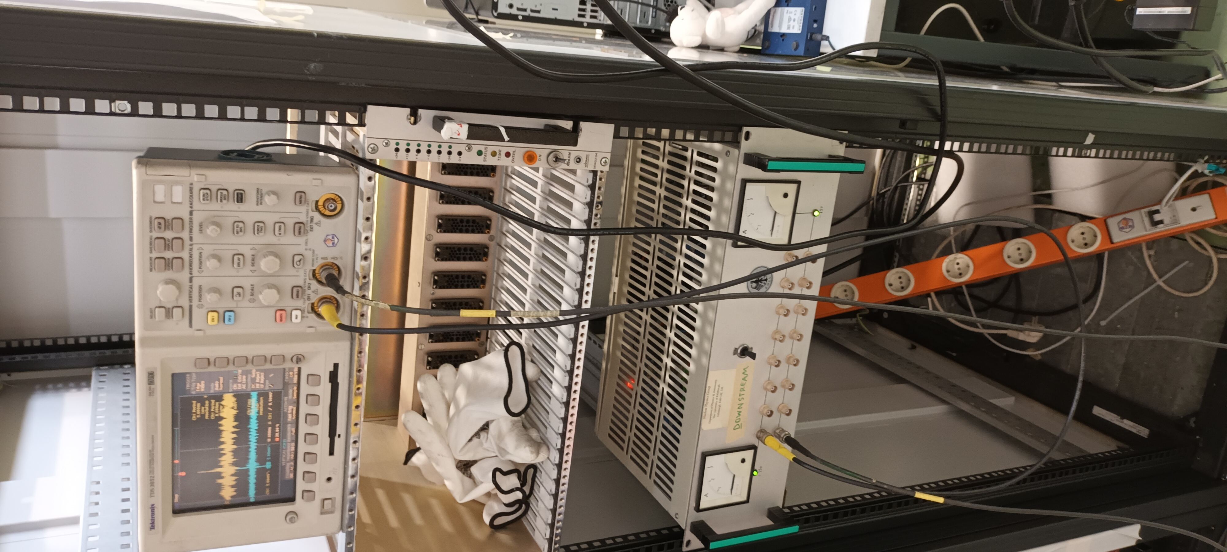
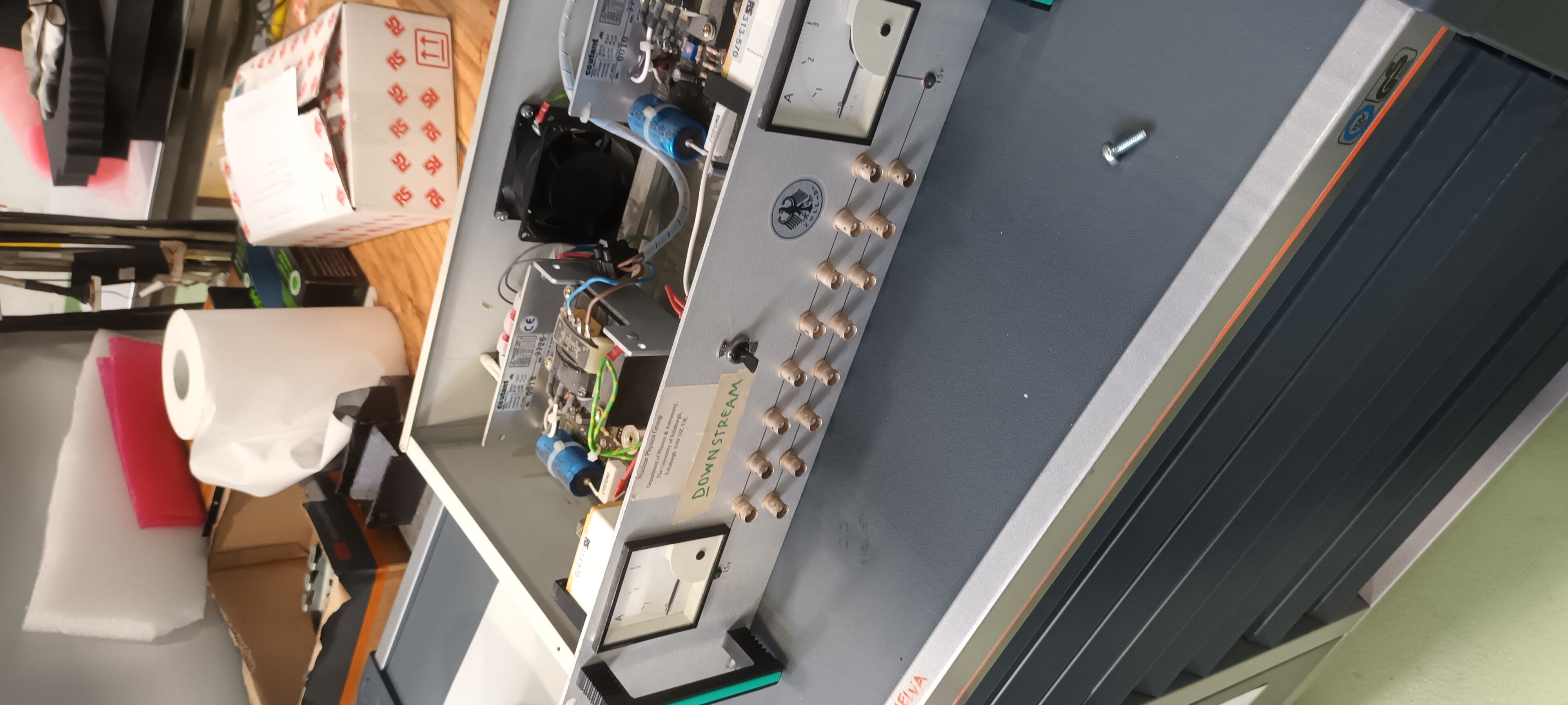
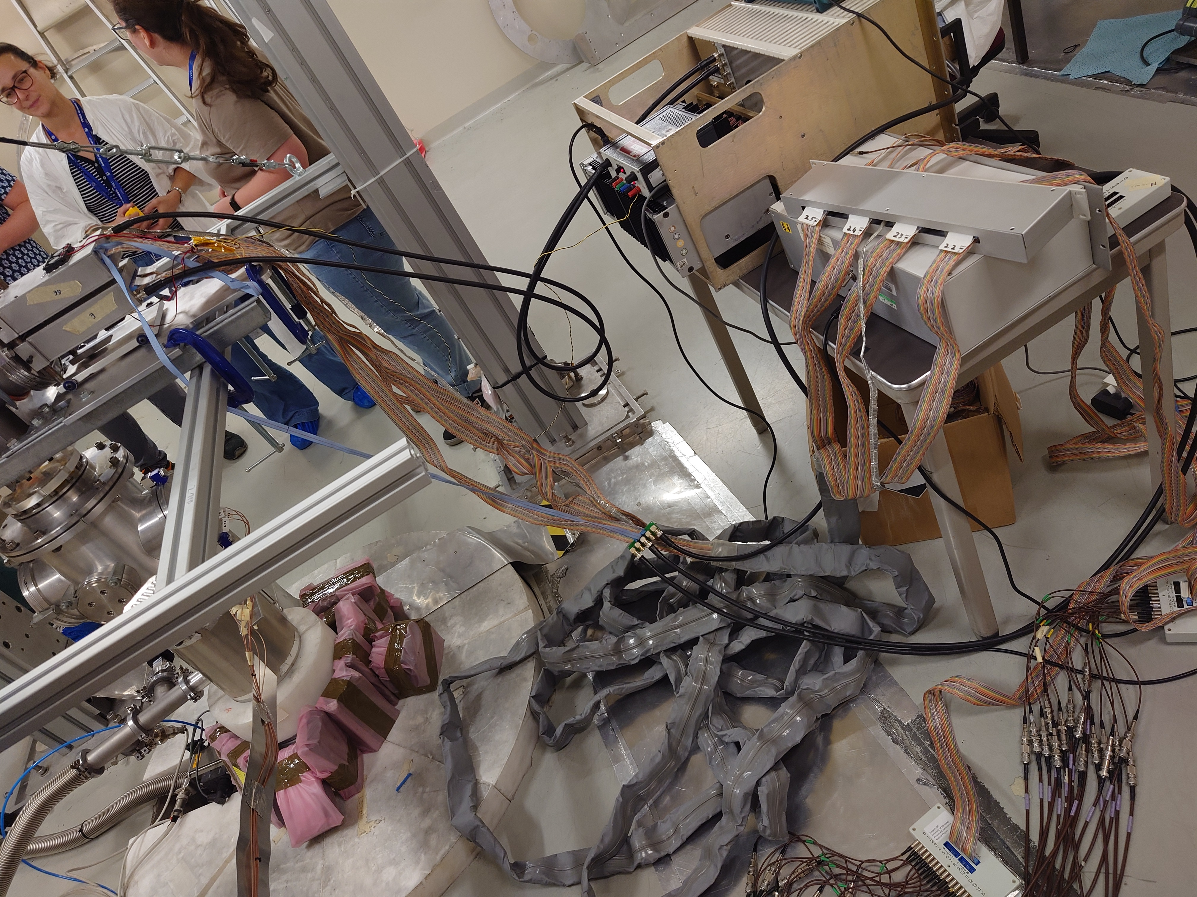
Following this test the same 2x RAL108 +/-15V PSUs were tested in the ISOLDE hall ( 19" rack adjacent to the HIE-ISOLDE GP scattering chamber ).


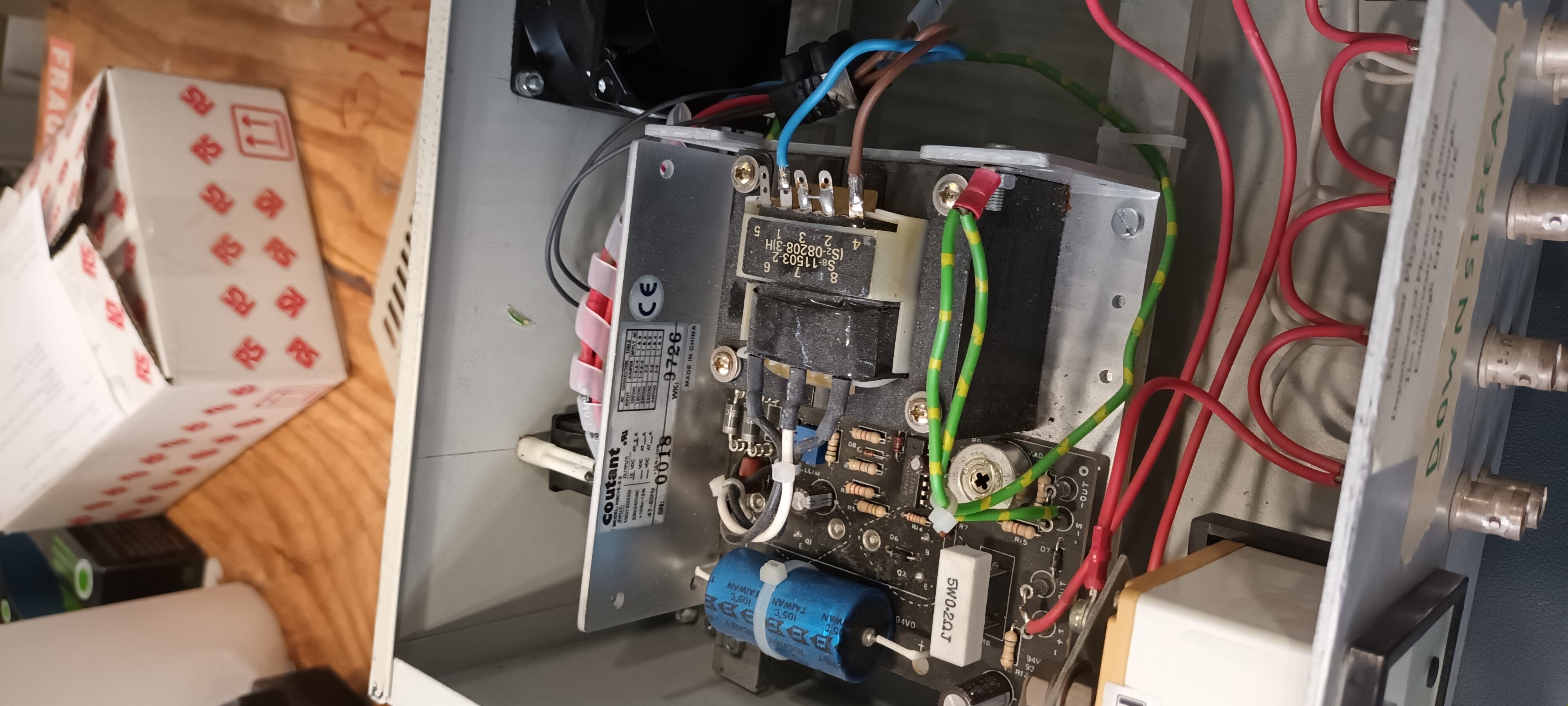
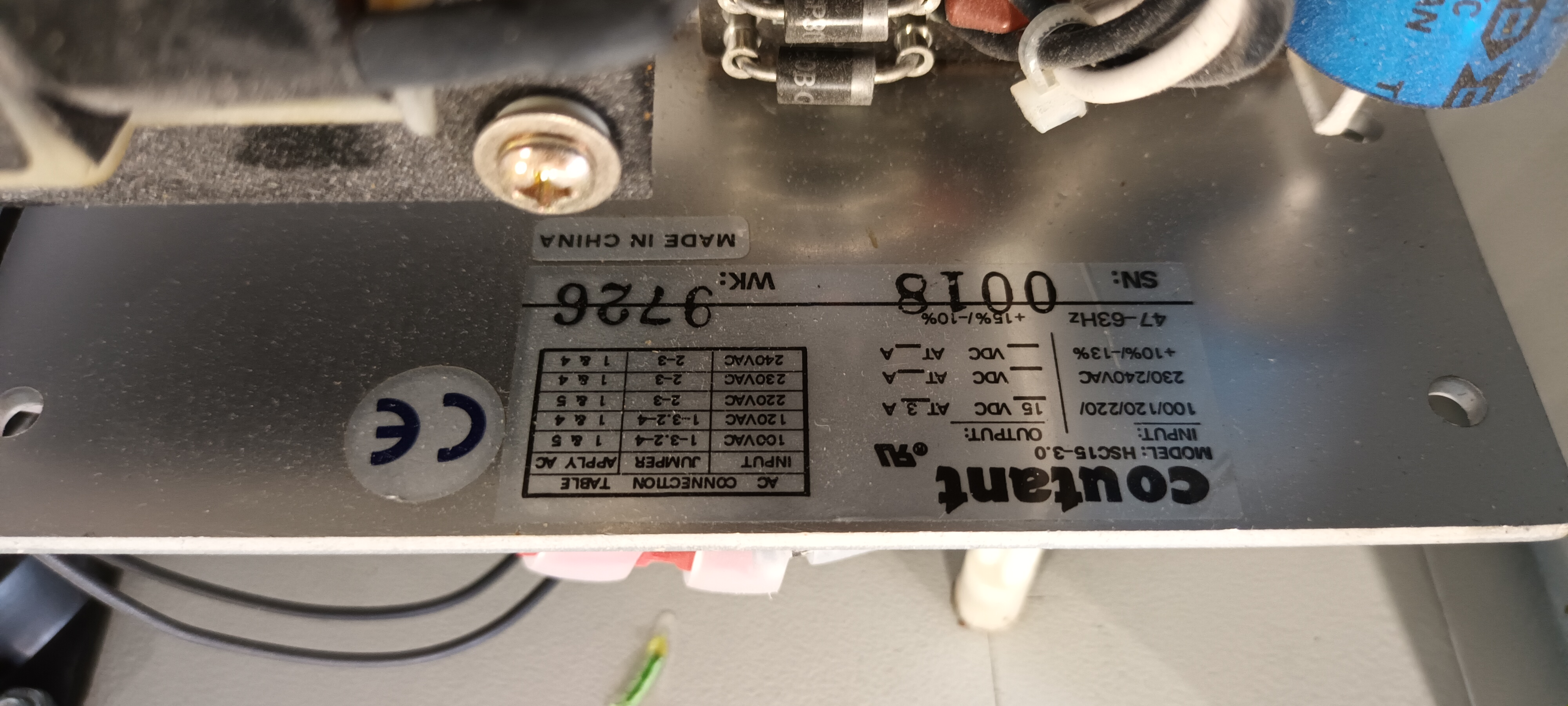
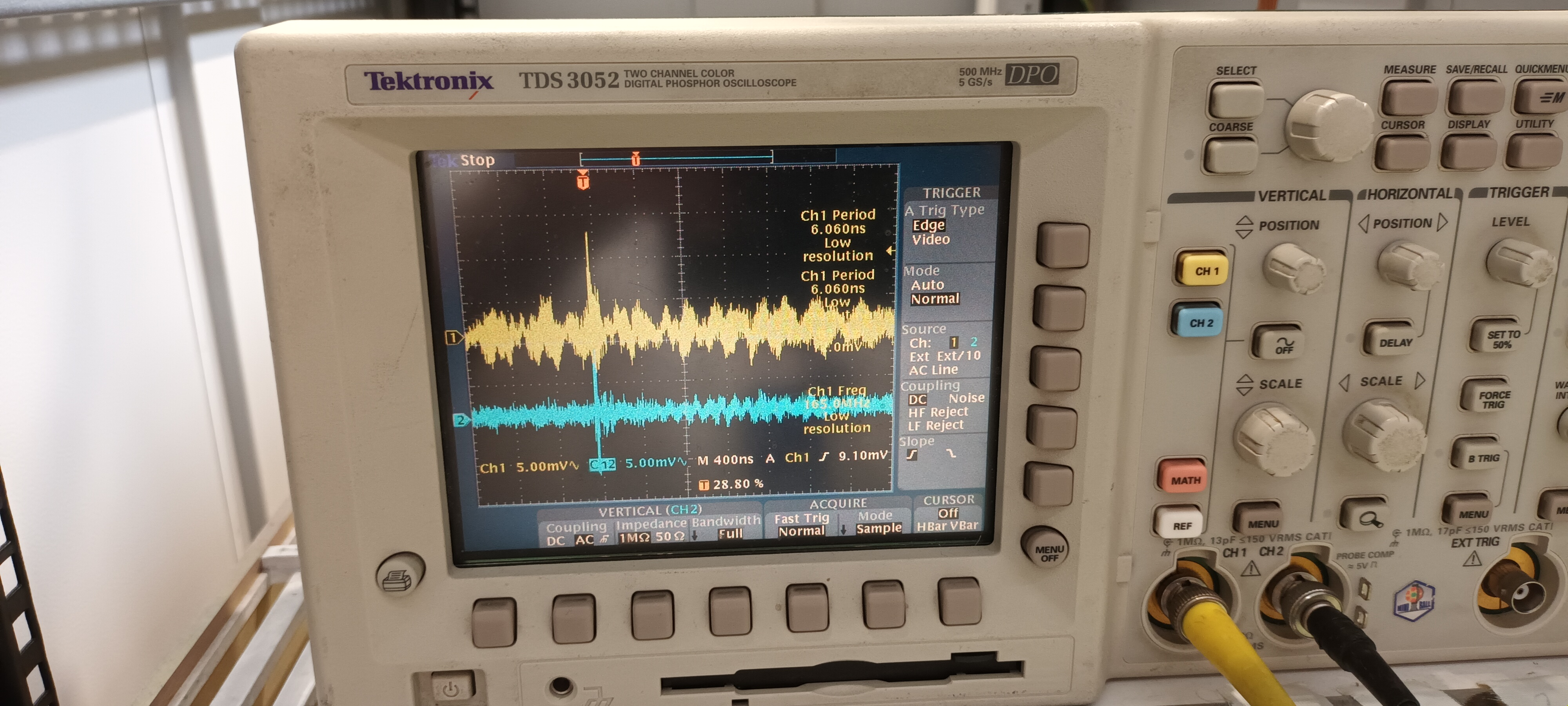
PSU #1 Coutant HSC15-3.0

Setup and PSU details - attachments 1-4

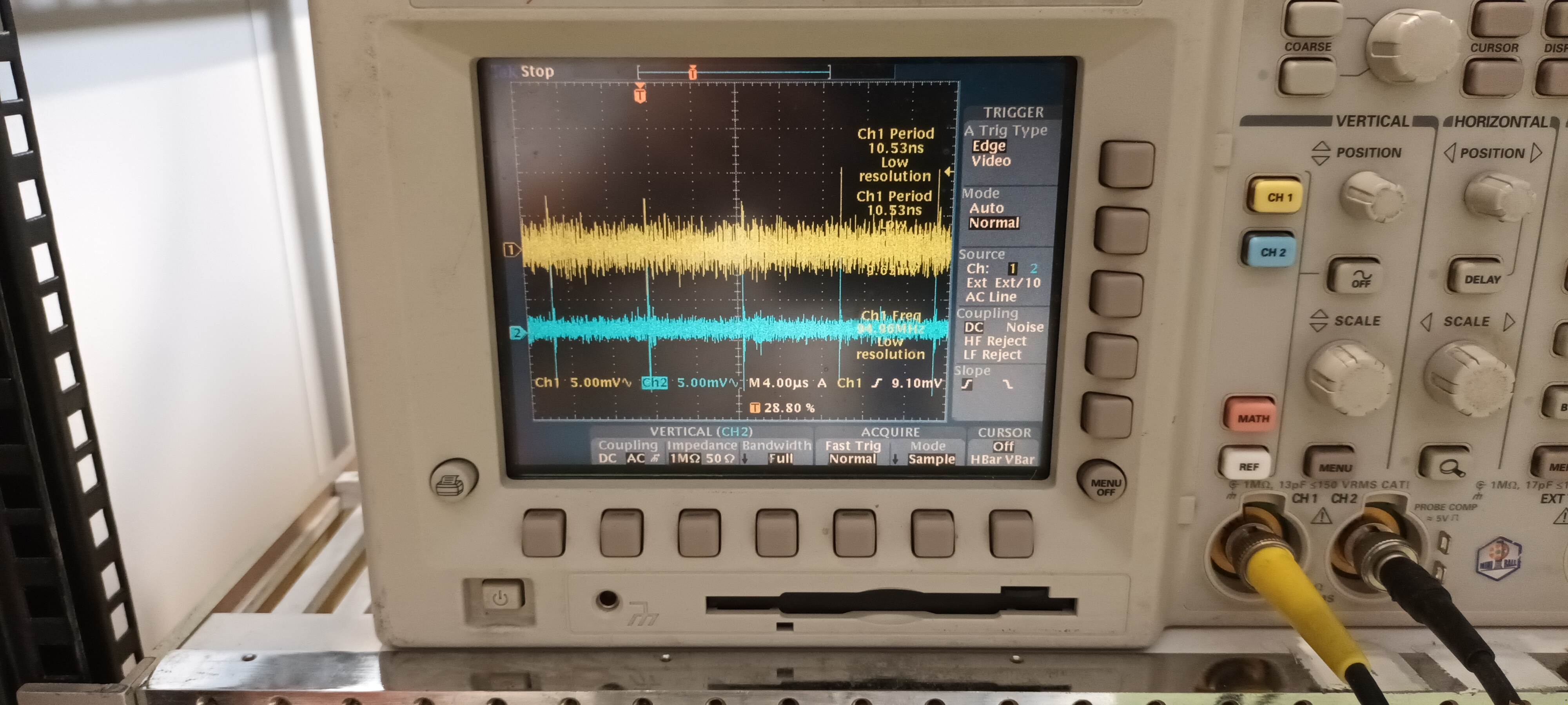
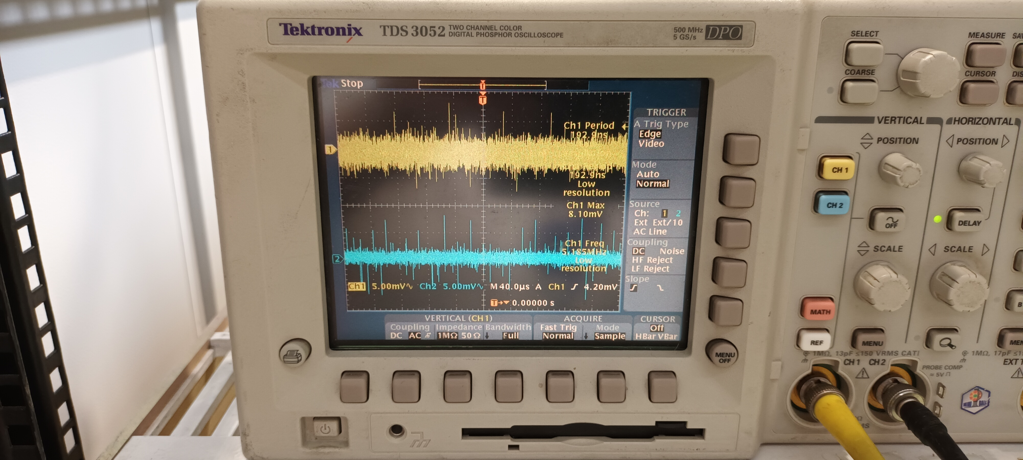
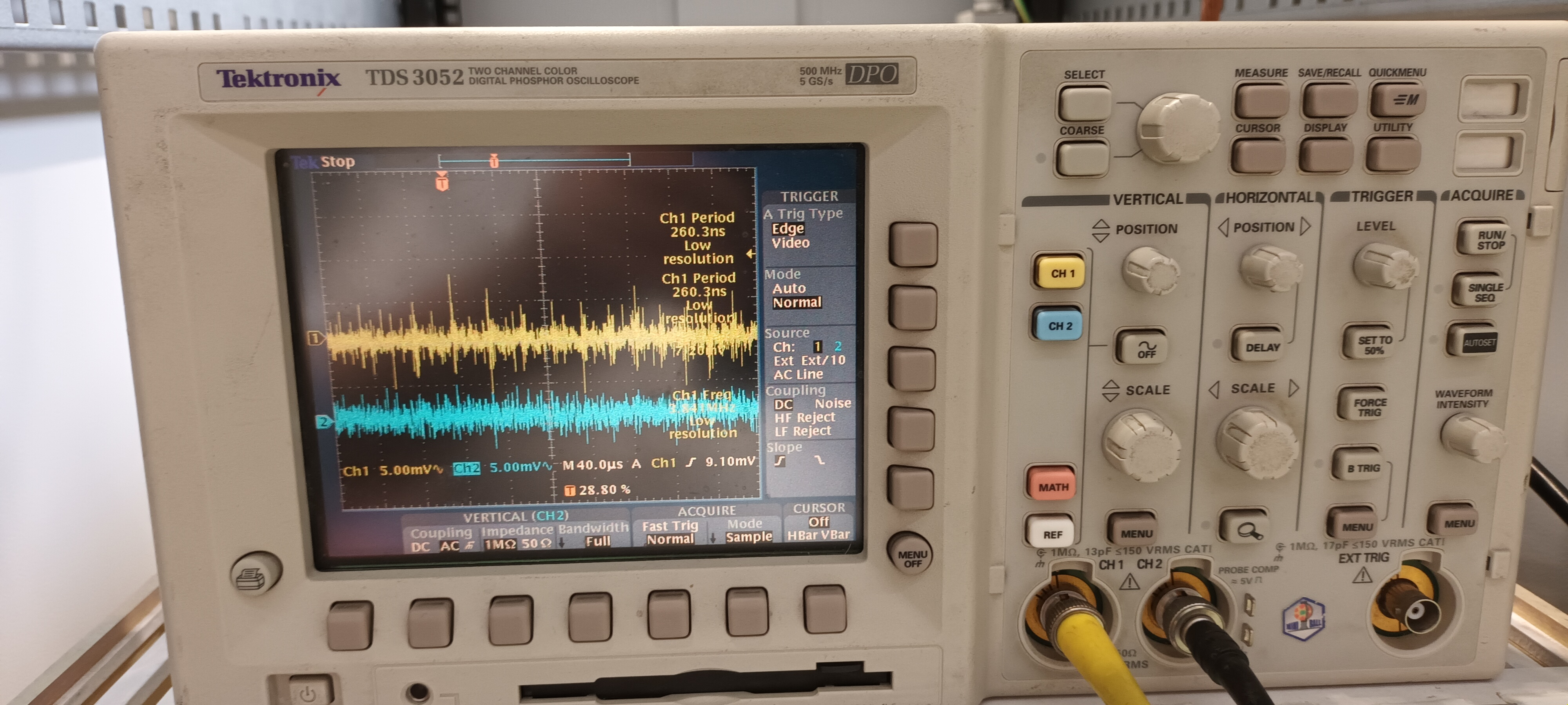
DSO ch#1 +15V AC/1M, ch#2 -15V AC/1M - y: 5mV/div x: 400ns, 4us & 40us/div - attachments 5-7


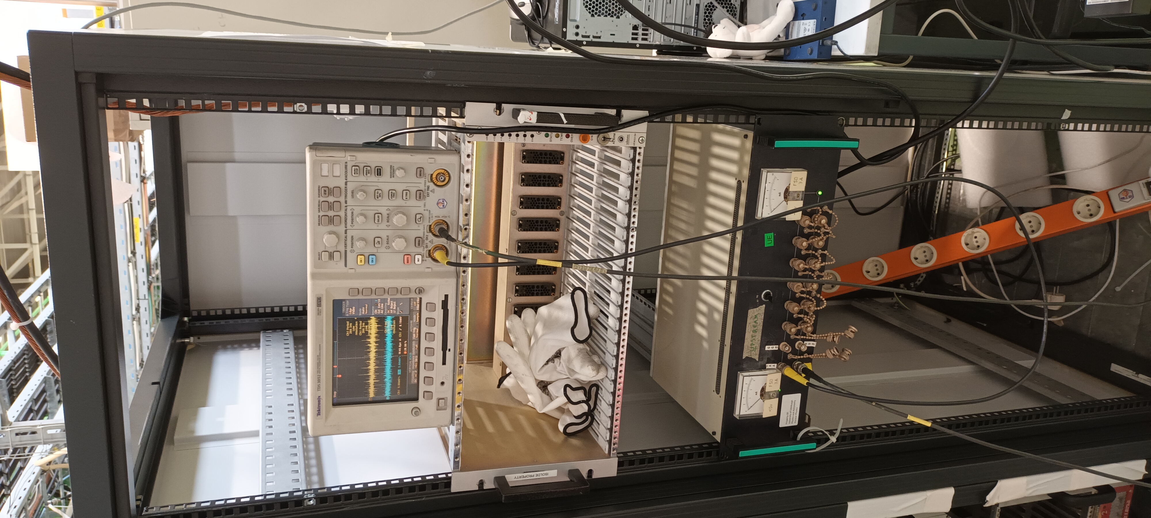
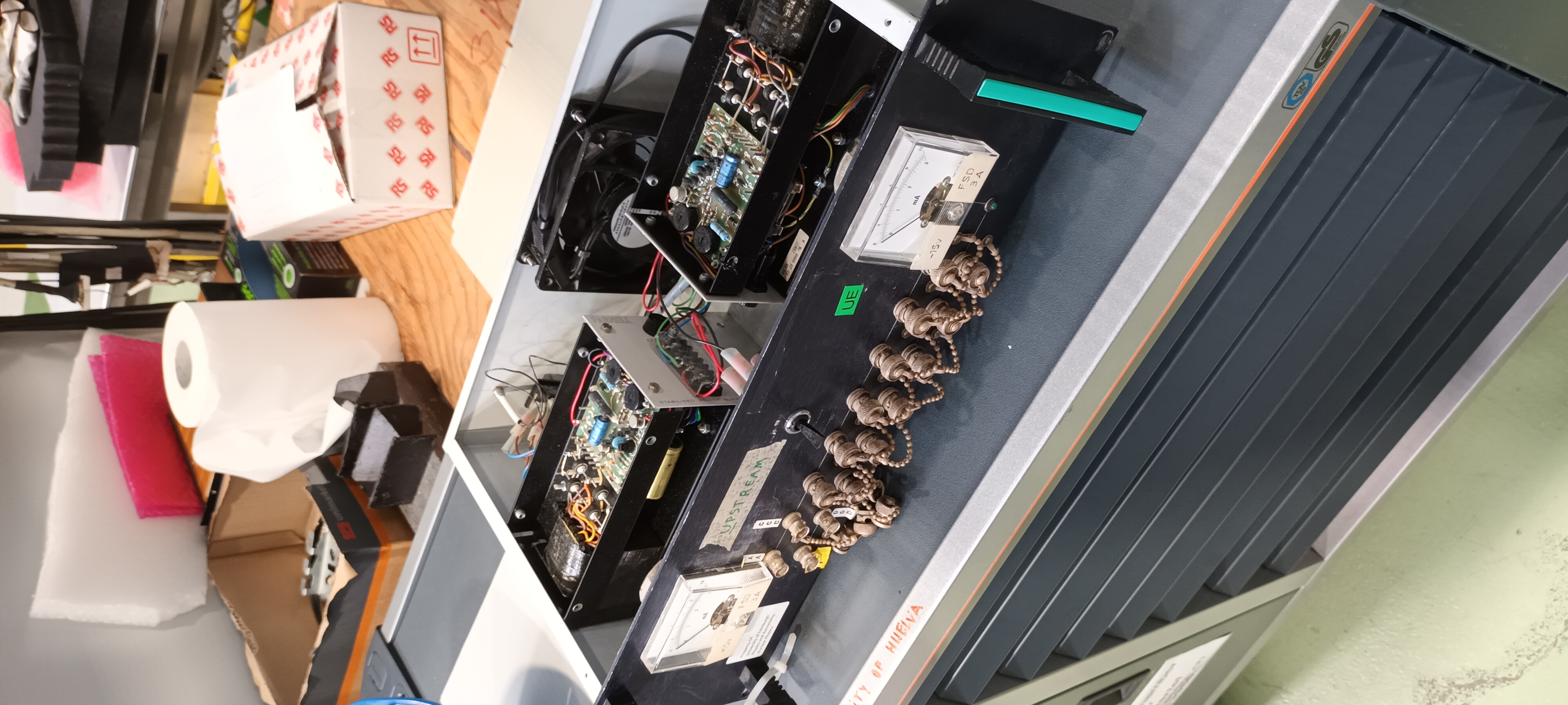
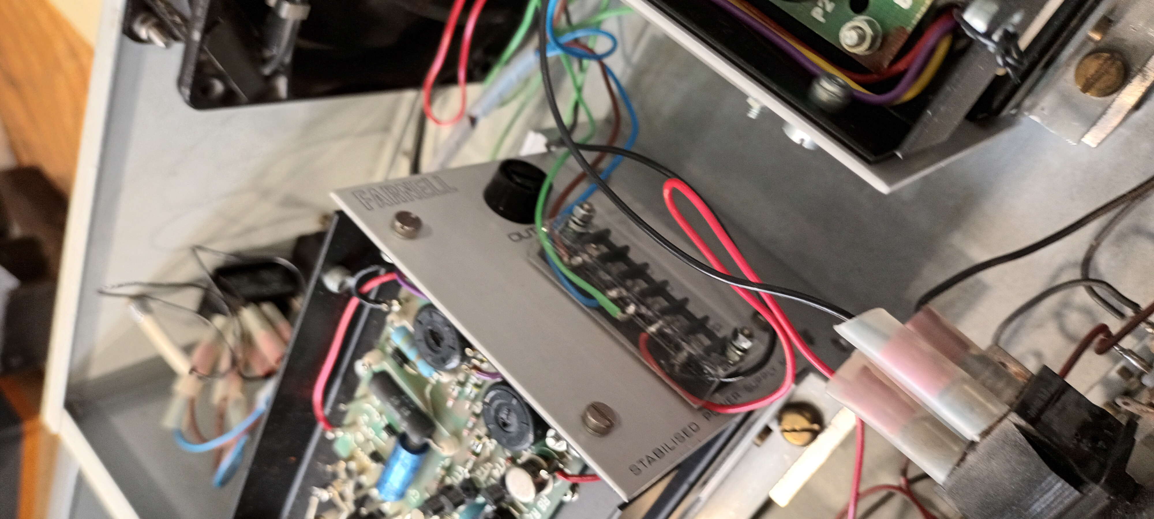
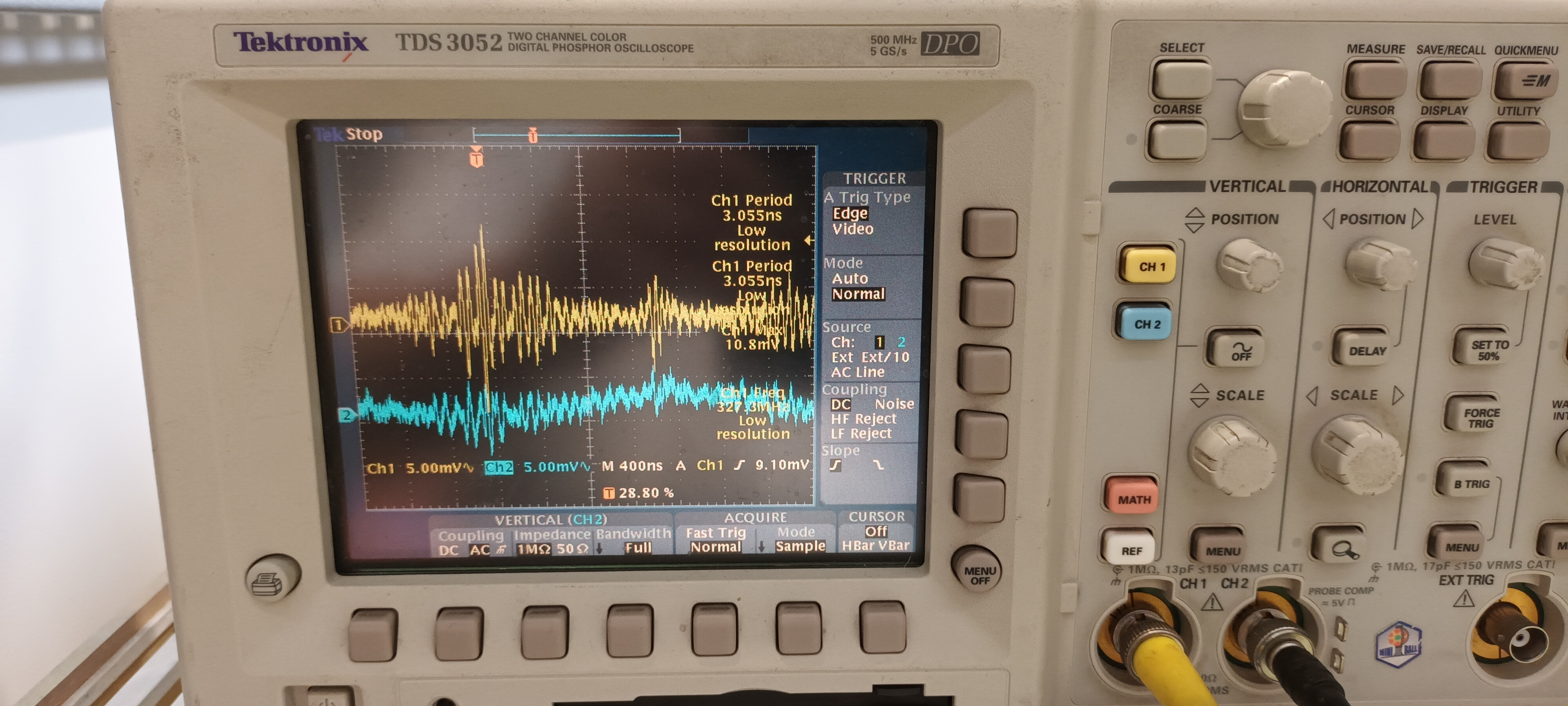
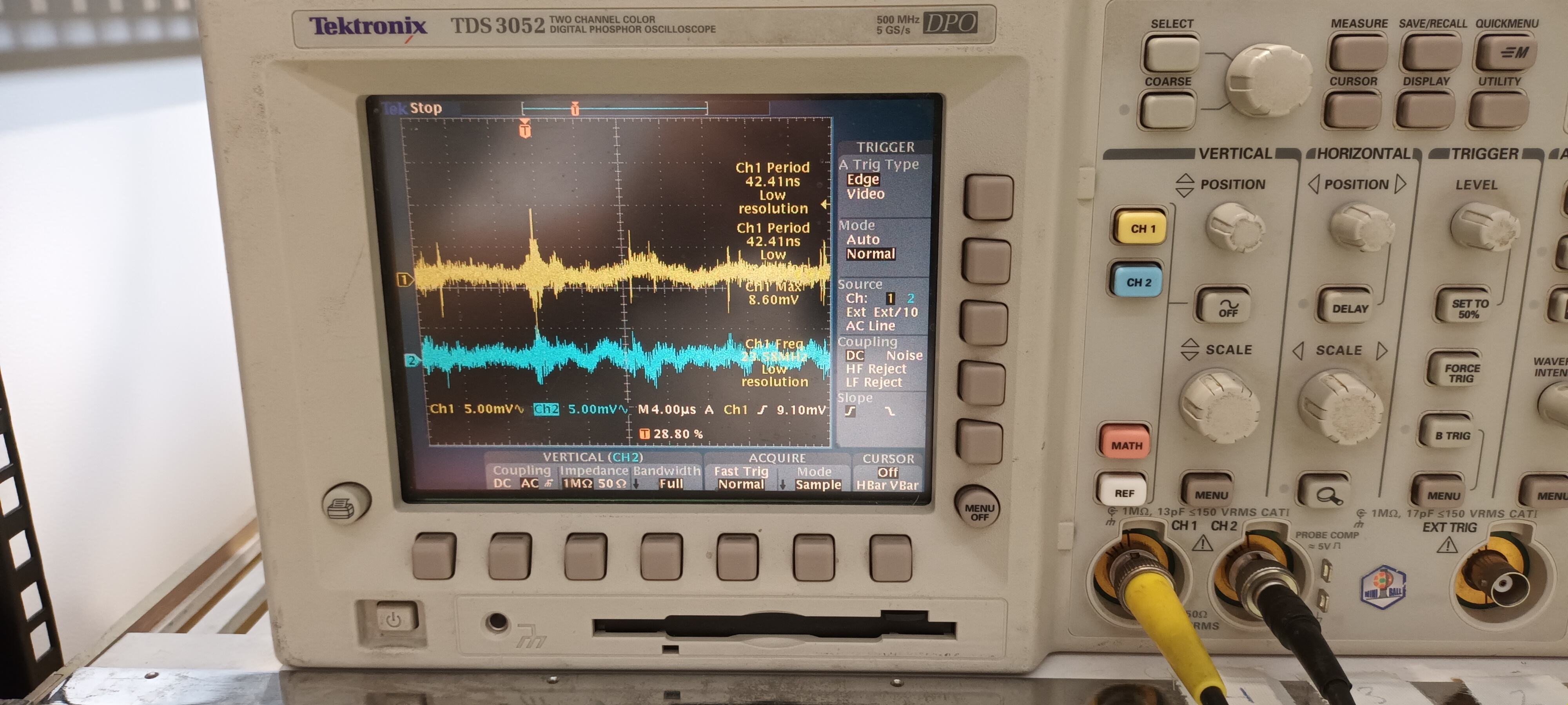
PSU #2 Farnell MX2

Setup and PSU details - attachments 8-10

DSO ch#1 +15V AC/1M, ch#2 -15V AC/1M - y: 5mV/div x: 400ns, 4us & 40us/div - attachments 11-13


Conclusion

The noise of the 2x RAL108 +/-15V PSUs differed somewhat ( frequency and structure of HF transients ) from each other in the ISOLDE test.

Compared to the EAR2, n_TOF test the amplitudes were c. 10x smaller and the HF transient frequency and structure differed.

This appears to confirm that the primary problem is the ac mains power in EAR2, n_TOF - input and/or output filtering is required. |
| Attachment 1: 20230814_110402.jpg
|
|
| Attachment 2: 20230814_111029.jpg
|
|
| Attachment 3: 20230814_111128.jpg
|
|
| Attachment 4: 20230814_111216.jpg
|
|
| Attachment 5: 20230814_110410.jpg
|
|
| Attachment 6: 20230814_110424.jpg
|
|
| Attachment 7: 20230814_110516.jpg
|
|
| Attachment 8: 20230814_110053.jpg
|
|
| Attachment 9: 20230814_110723.jpg
|
|
| Attachment 10: 20230814_110738.jpg
|
|
| Attachment 11: 20230814_110158.jpg
|
|
| Attachment 12: 20230814_110142.jpg
|
|
| Attachment 13: 20230814_110105.jpg
|
|
|
61
|
Sat Aug 12 09:24:19 2023 |
Nikolay Sosnin | 26Al Protons |
Here is a Google spreadsheet for counting protons for the runs:
https://docs.google.com/spreadsheets/d/1INX8G9GAu-M70SdZdz55qXnMZNXKXLW7xfFH-eaLuQw/edit?usp=sharing |
|
60
|
Fri Aug 11 16:50:58 2023 |
Nikolay Sosnin | EDET24 |
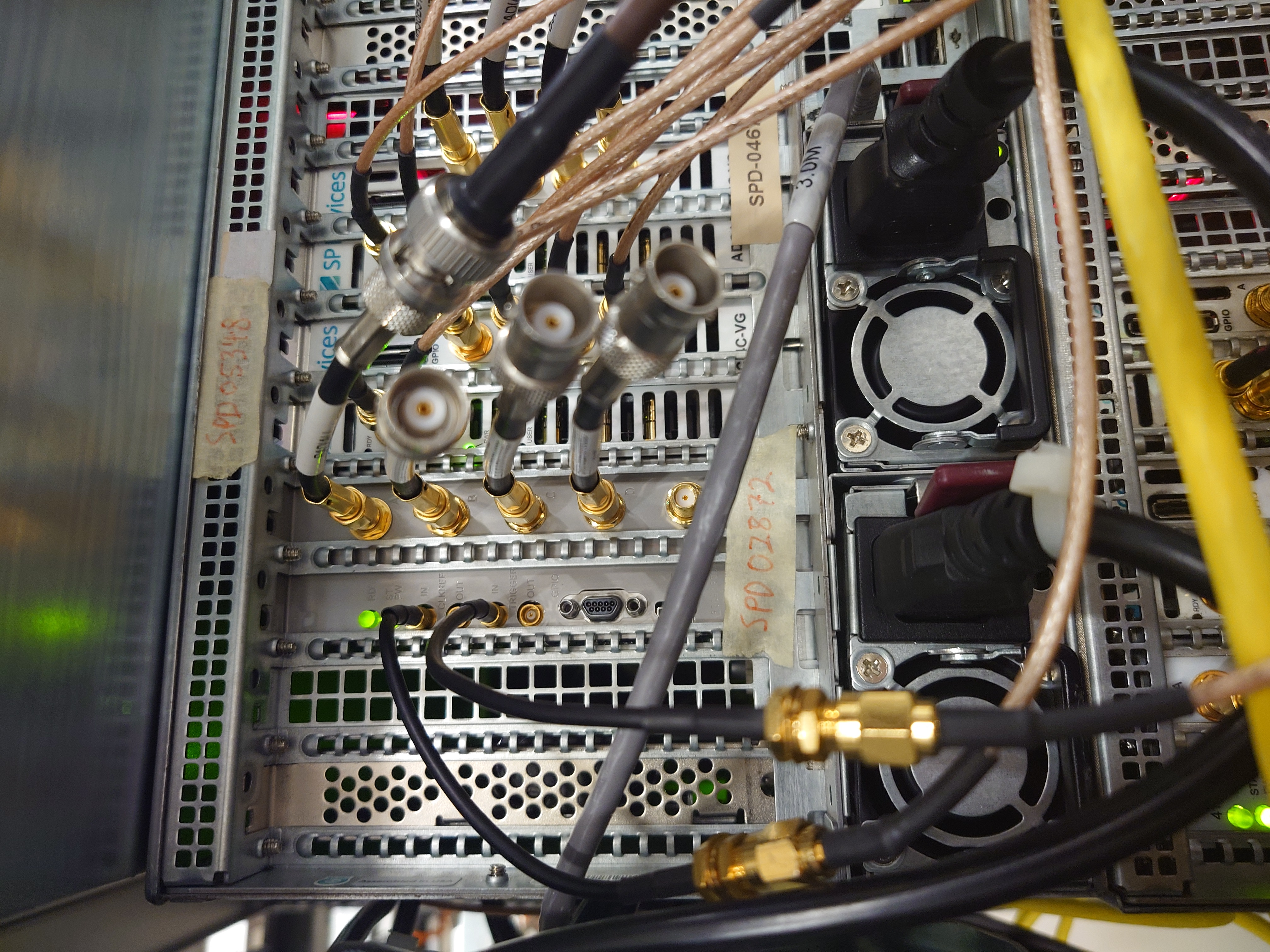
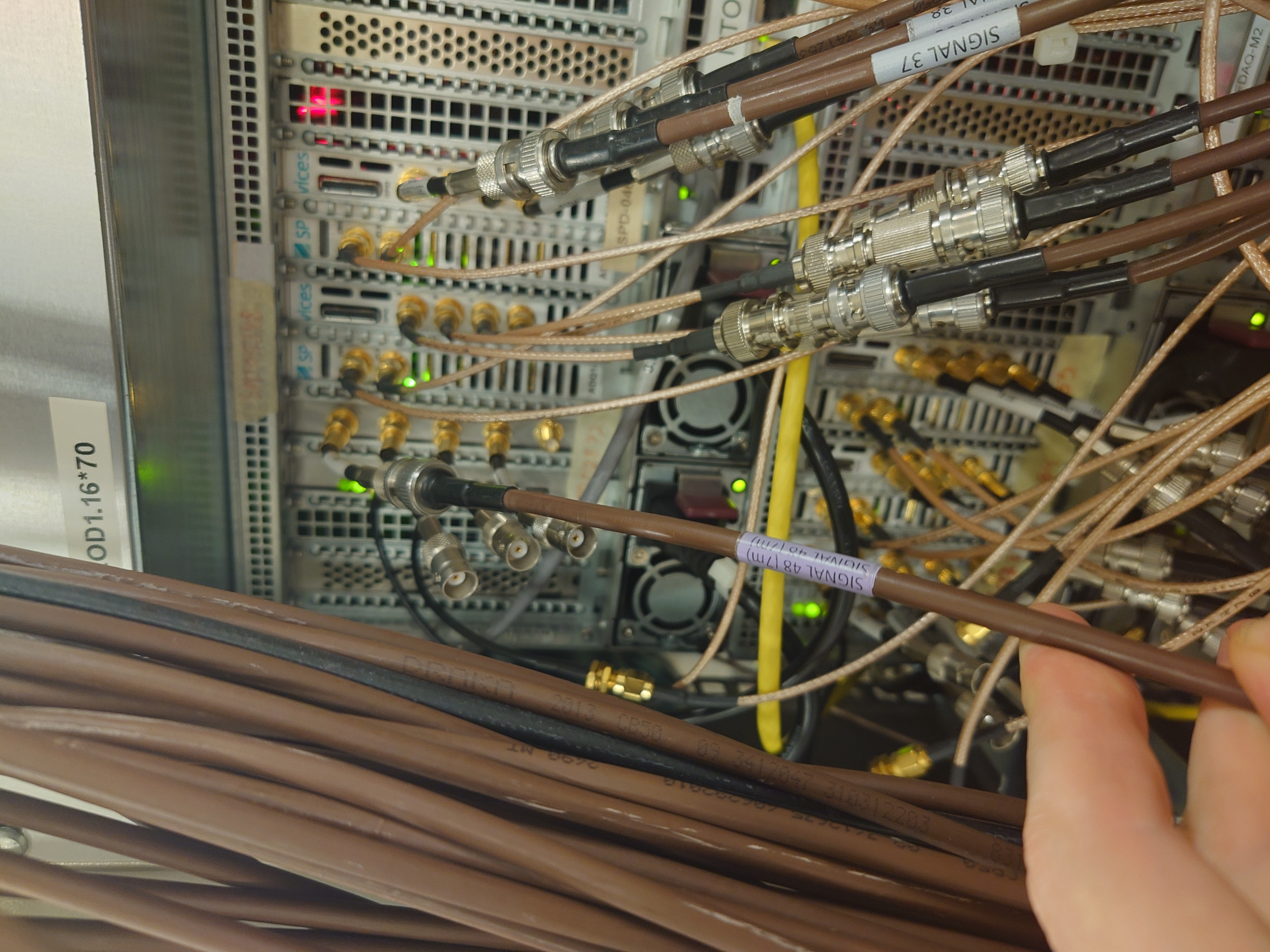
After inserting aluminium target, previously-dead channel 24 on EDET was re-plugged into a 12-bit card SPD02872. It is the only EDET on 12-bit card, the rest are on 14-bit. From pulsers, there appears to be a 90 ns offset from this EDET to others, with EDET24 preceeding the rest. The last channel on 14-bit cards was broken, hence havng to use 12-bit. |
| Attachment 1: EDET24_Card.JPG
|
|
| Attachment 2: EDET24_Cable.JPG
|
|
|
59
|
Fri Aug 11 13:16:56 2023 |
Nikolay Sosnin | E Front Incorrect Cabling |
E front 2x16-way to 1x34-way IDC cable from the Junction Box to the IDC-Lemo 00 adaptor was found to be inserted upside-down - the 16-way IDC connectors did not have polarisation keys - meaning the E detector p+n junction strip signals collected with 26Al for the first night are not working. Signals from the dE p+n junction strips and E n+n Ohmic strips will be OK. The mistake occurred at the conclusion of the noise tests yesterday - see https://elog.ph.ed.ac.uk/nToF/52
The 2x16-way to 1x34-way IDC cable without polarisation keys has now been replaced.
Run 216417 and onwards have correct cabling. For runs before that, E back and dE are still reliable. |
|
58
|
Fri Aug 11 13:06:54 2023 |
Annie | Signal Spreadsheet info |
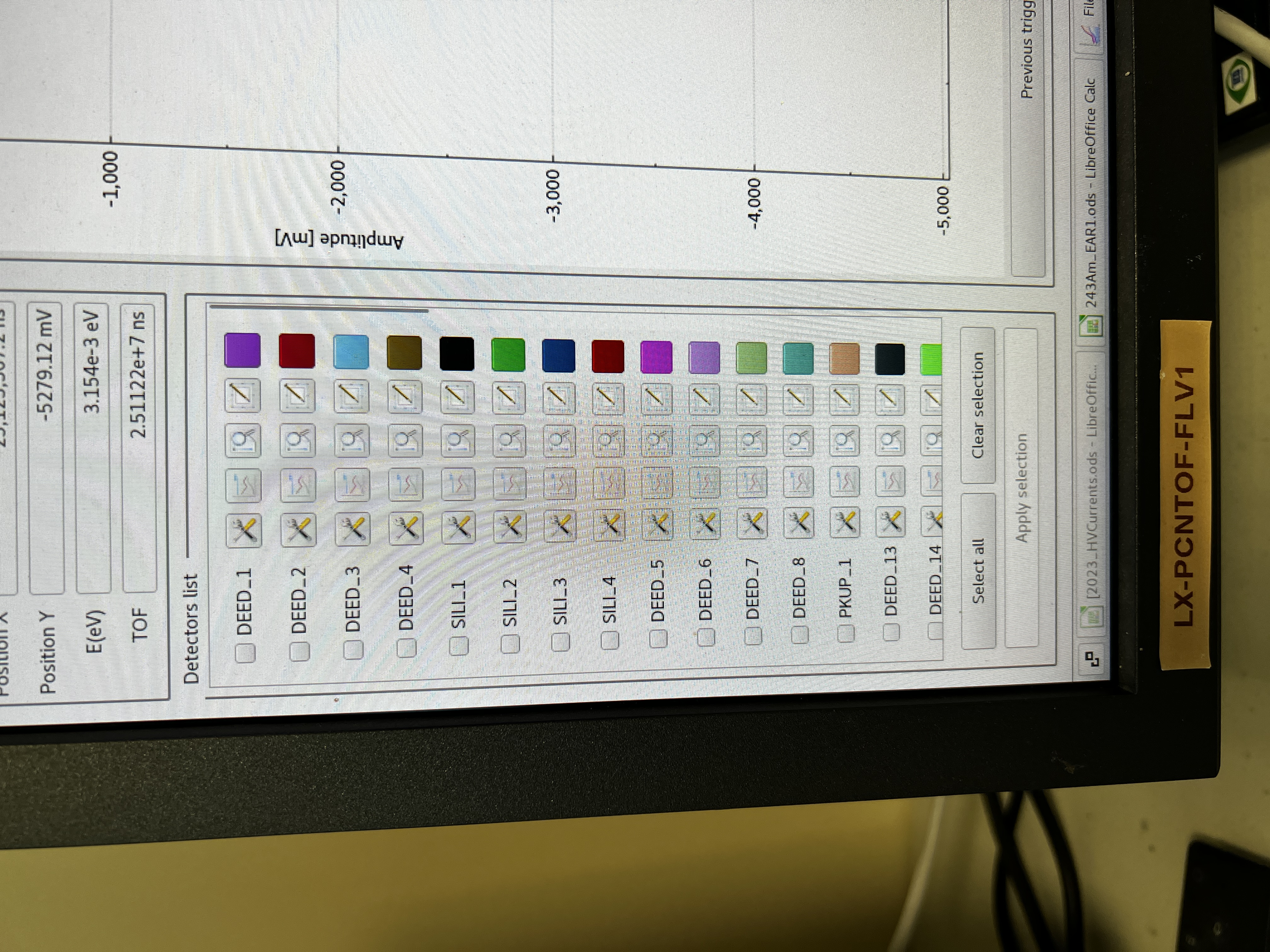
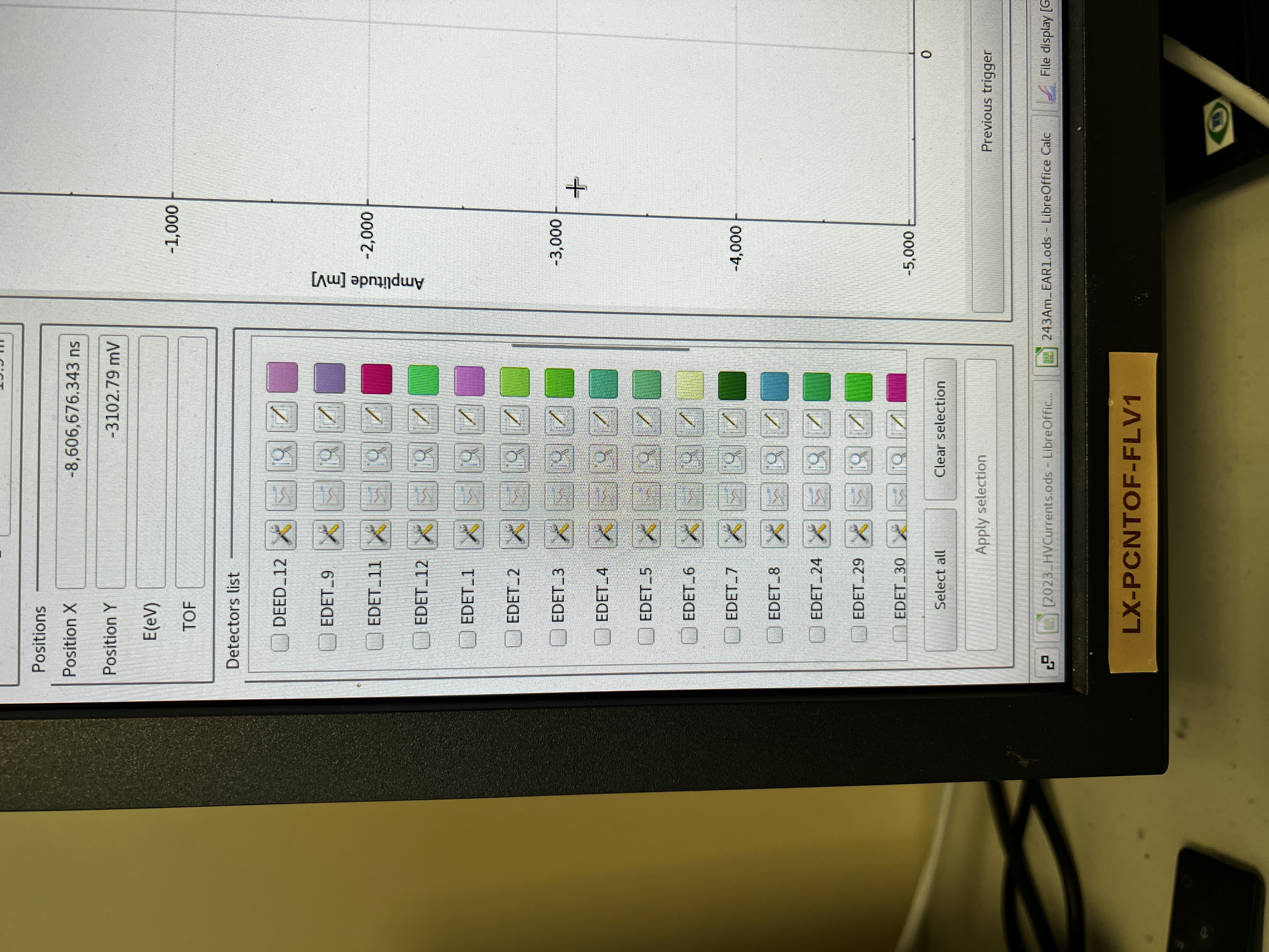
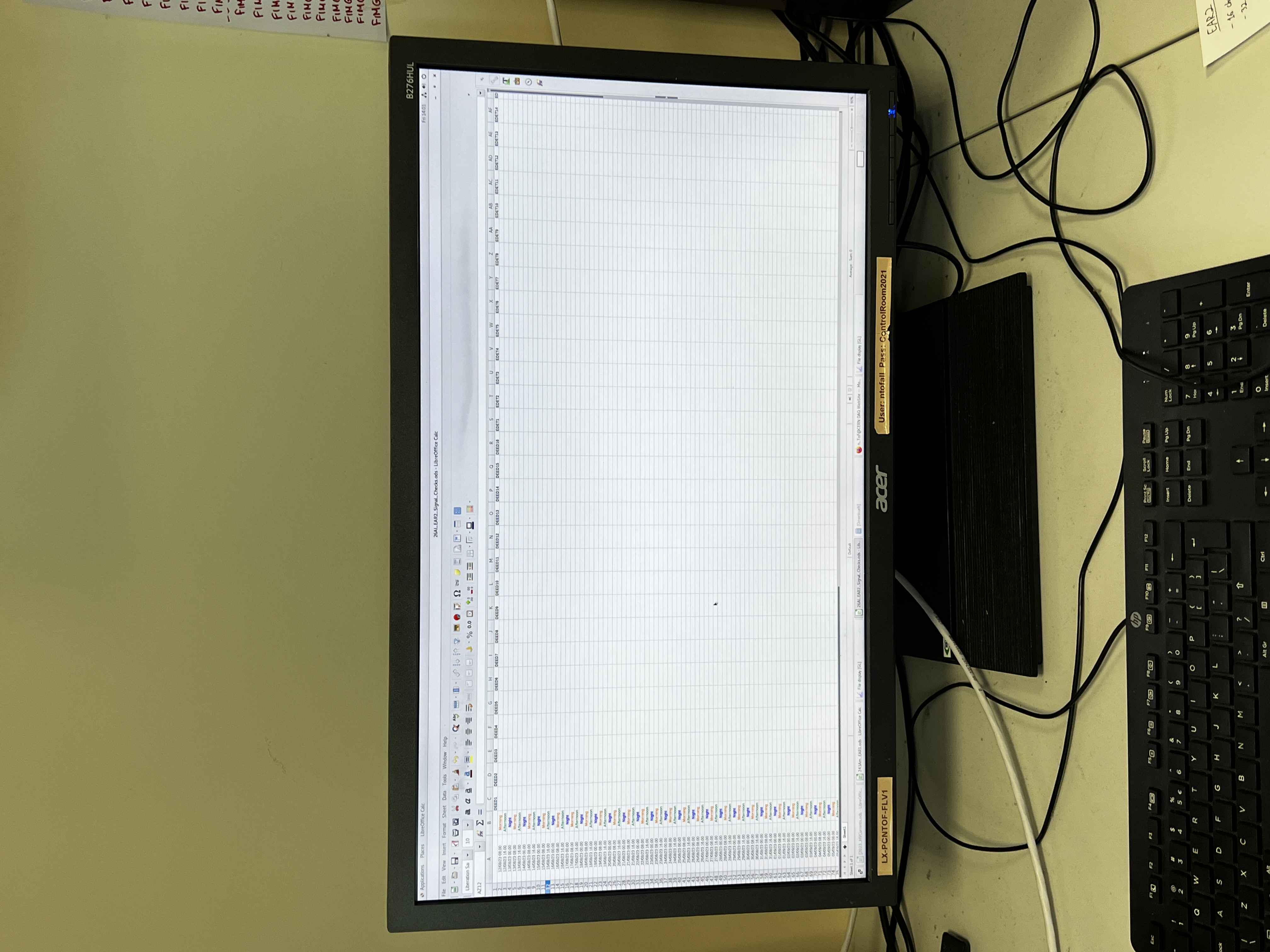
Spreadhseet made for shifters to manually enter that they have checked each signal and that they can see gamma-flashes. It is saved as "26Al_EAR2_Signal_Checks.ods", it is located on the second monitor on the right of the control room, next to the monitor used to see the beam intensity (same monitor used to see signals).
It will stay open throughout the campeign. Shifters have been told to check signals more than just the once to record that they're okay, and there is a comments box for shifters to add any comments/issues that arises after they have recorde that they have checked the signals at least once. |
| Attachment 1: IMG_2920.JPG
|
|
| Attachment 2: IMG_2921.JPG
|
|
| Attachment 3: IMG_2922.JPG
|
|
|
57
|
Fri Aug 11 10:12:02 2023 |
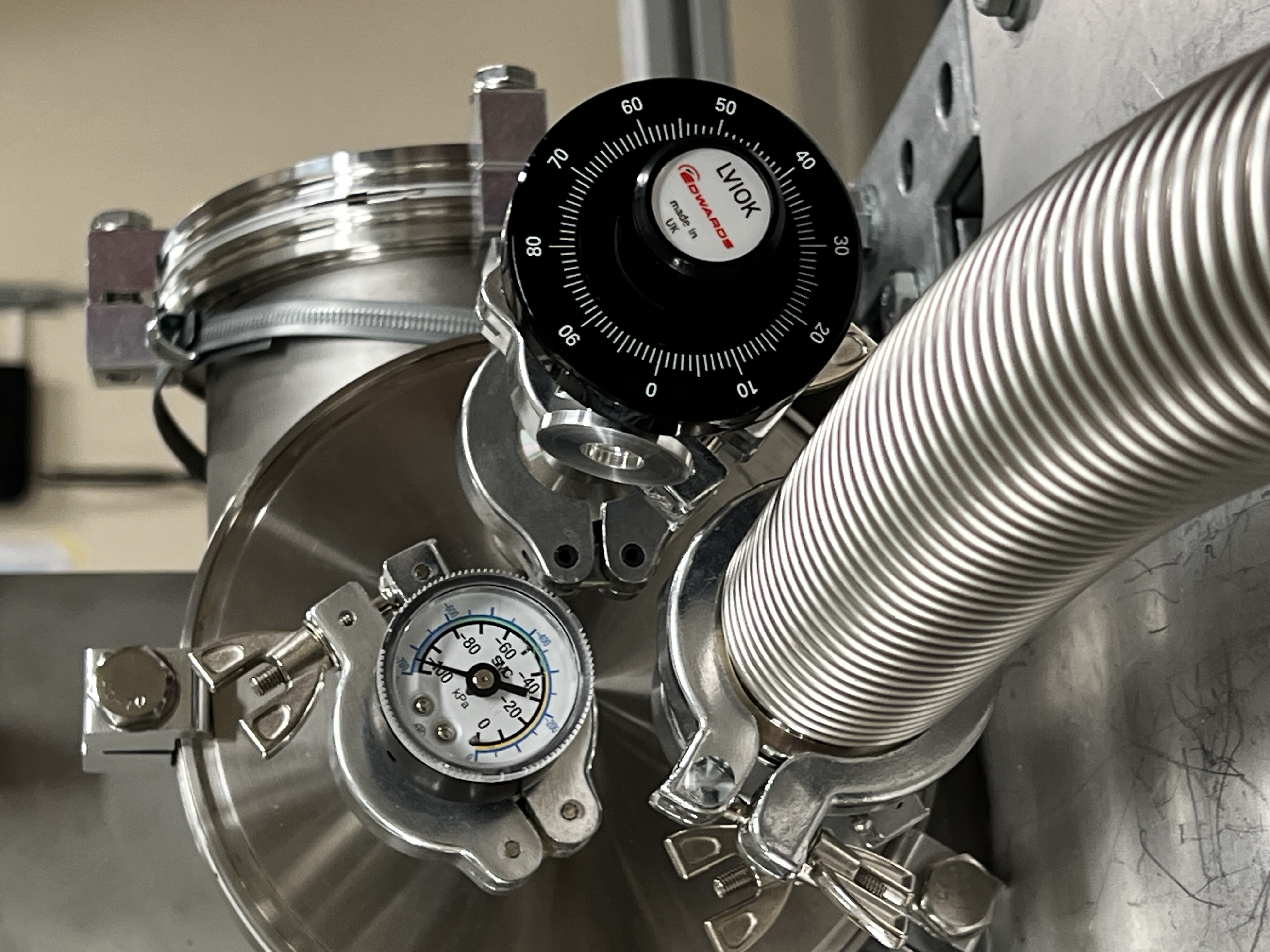
Annie | Pressure, voltage and current check |
|
| Attachment 1: IMG_2915.JPG
|
|
| Attachment 2: IMG_2916.JPG
|
|
| Attachment 3: IMG_2918.JPG
|
|
|
56
|
Fri Aug 11 10:02:08 2023 |
TD, NS, AR | Noise |
Check RAL108 +/-15V PSU

Measured output voltages +15.21V -15.18V - OK

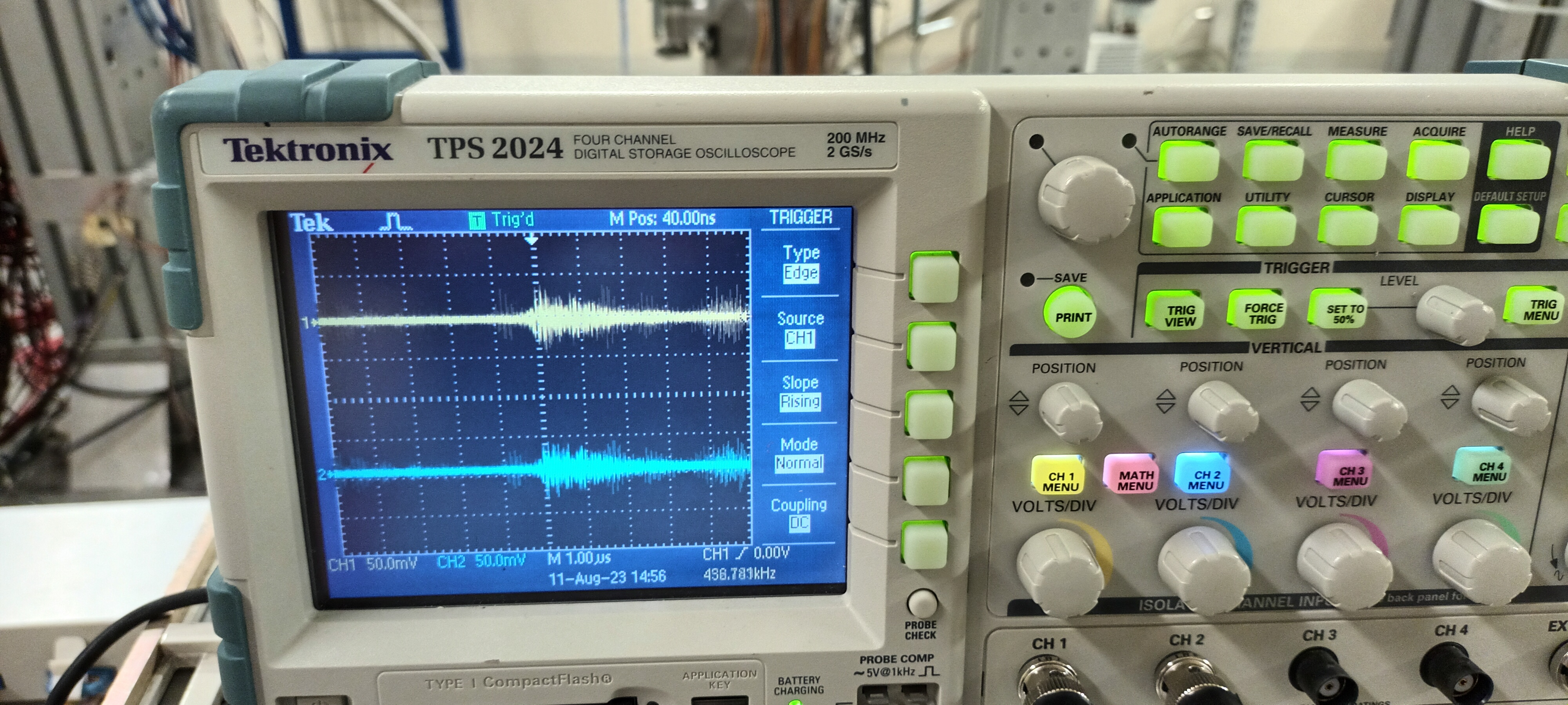
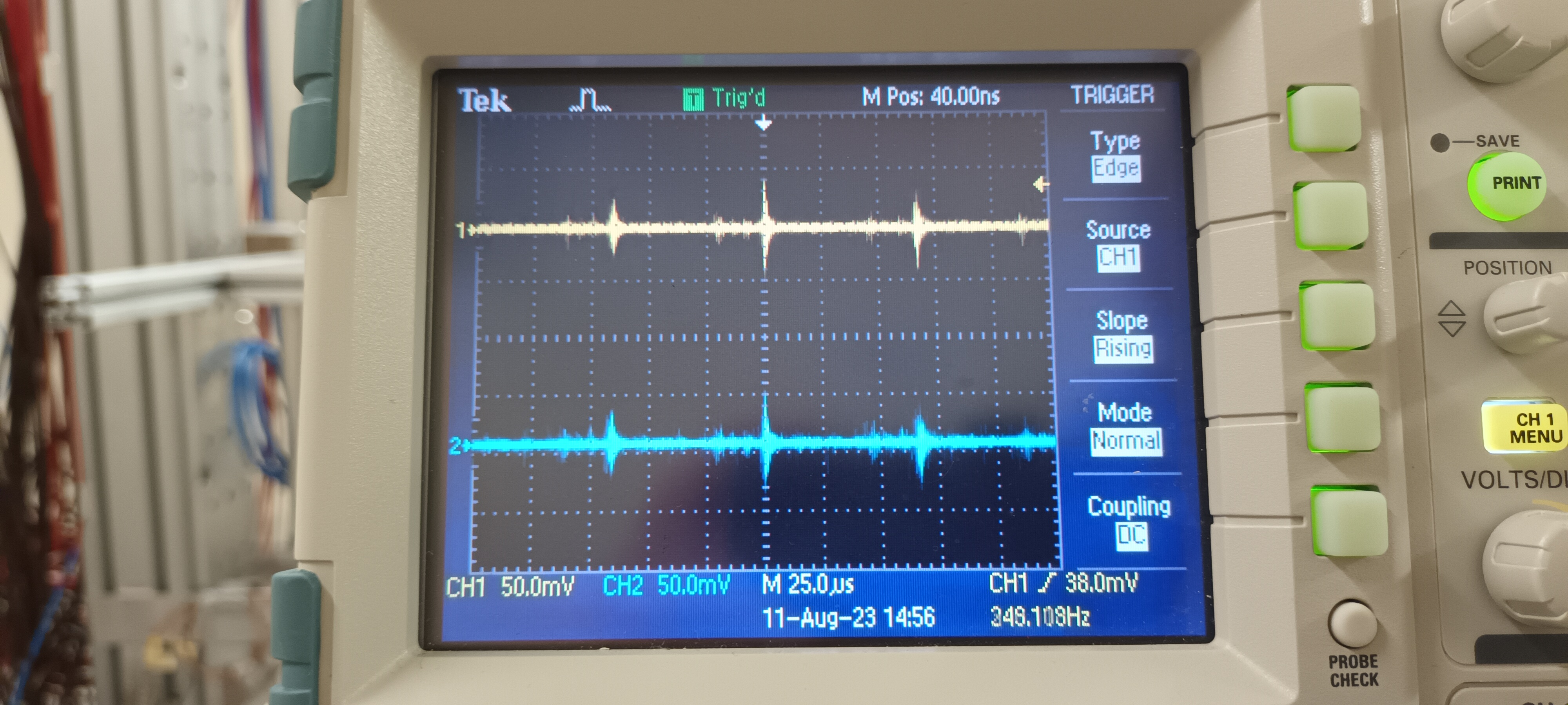
Observe output voltages with DSO ( ch #1 AC/1M +15V, ch #2 AC/1M -15V ) - see attachments 1 & 2

What we should observe is c. 1mV rms ( white ) noise but we clearly observe similar noise transients ( c. 60us period with HF structure ) to those observed at RAL108
outputs. The RAL108 preamplifier units do have RC filters on the +/-15V - typically c. 100 Ohm and 4.7uF. Some additional, inline filtering with a lower rolloff
frequency may be required.

>
> Observe c. 2mV p to p noise with DSO ( Z_in = 50 Ohm ) c. 60us period with HF structure. DSO connected to junction box via 34-way IDC - 16x Lemo-00 adaptor.
>
> Origin of noise upstream of 4x34-way to 8x16-way Junction Box. Not microphonics from Edwards RV5 Rotary Pump.
> No change observed with simple ground connections between NIM bin/+/-15V PSU/Junction Box and MSL type W1 preamplifier units/vacuum chamber/support assembly.
>
>
> Estimate of electronic noise
>
> Pulser BNC PB-5
>
> Amplitude 0.5V
> Attenuation x1
> Decay time 1ms
> Frequency 50Hz
>
> Preamplifier RAL108
> Output impedance 100 Ohm
> Sensitivity 20mV/MeV ( into high Z load ), 6.7mV/MeV ( into 50 Ohm load )
>
> Amplifier EG&G Ortec 571
> Input terminated by 50 Ohm
> Gain x1 (internal) x 1.0 (fine gain) x 50 (coarse gain ) = 50
> Shaping time 0.5us
>
> MCA Amptek 8000D
> Input FSR 10V
> 12 bit ADC
>
>
> Nominal gain = 6.7mV/MeV x 50 = 335mV/MeV
>
> 12 bit ADC input FSR = 10V / 0.335V/MeV = 29.85MeV FSR or 7.3keV/channel
>
>
> dE p+n junction strip # 4 ( of 0-15 )
>
> pulser peak centroid = 799.8 ch
> pulser peak width = 7.8 ch FWHM = 57 keV FWHM
>
>
> E p+n junction strip # 4 ( of 0-15 )
>
> pulser peak centroid = 864.8ch
> pulser peak width = 3.5 ch FWHM = 26 keV FWHM
>
>
> E n+n Ohmic strip # 4 ( of 0-15 )
>
> pulser peak centroid = 913.0 ch
> pulser peak width = 5.3 ch FWHM = 39 keV FWHM
>
>
> Noise estimates are probably accurate to c. 10% level. |
| Attachment 1: 20230811_104233.jpg
|
|
| Attachment 2: 20230811_104253.jpg
|
|
|
55
|
Fri Aug 11 09:17:28 2023 |
Annie | Li target scans |
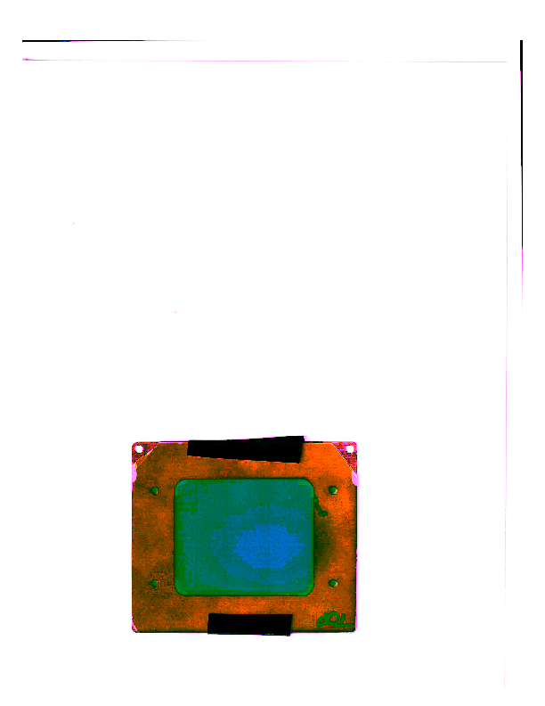
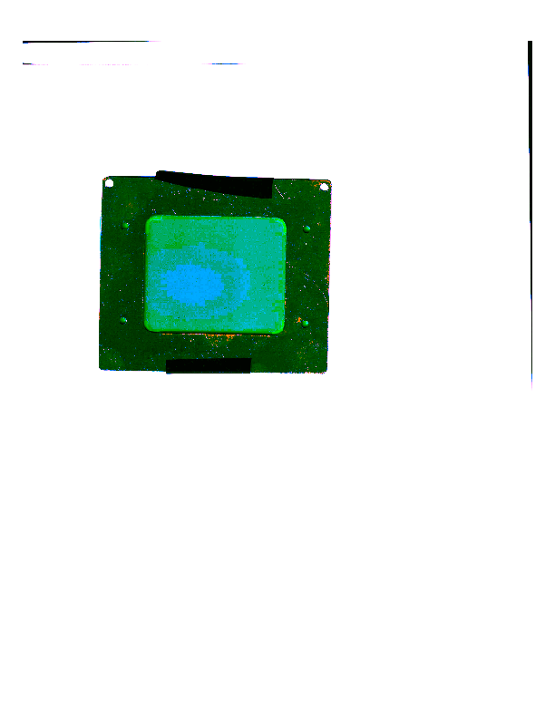
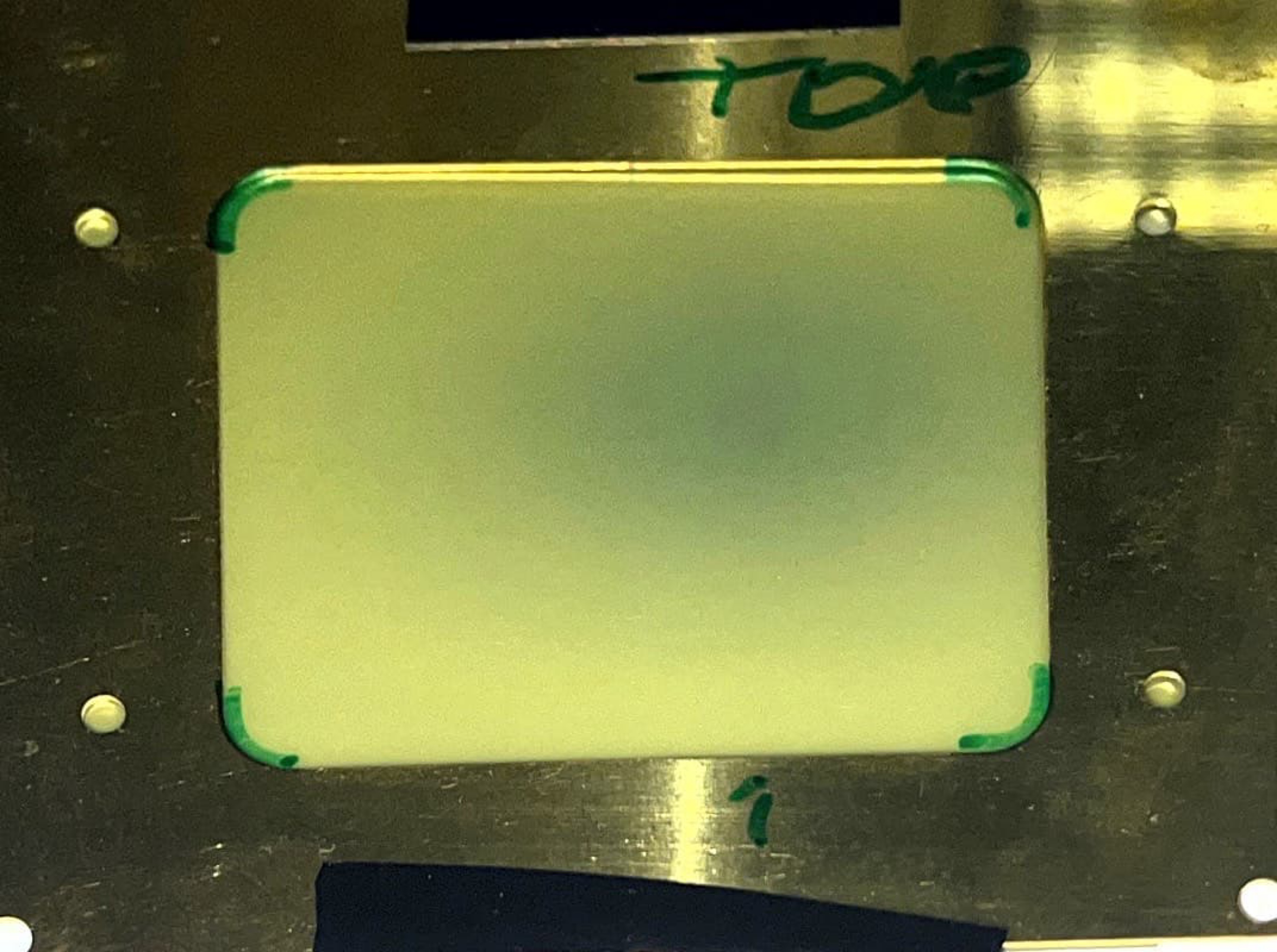
Processed scans of both sides of the Li target showing the beam spot, and an image showing what it looks like to the eye. |
| Attachment 1: 7Li_foil_side1_post_processed.pdf
|

|
| Attachment 2: 7Li_foil_side2_post_processed.pdf
|

|
| Attachment 3: IMG_2914.JPG
|
|
|
54
|
Fri Aug 11 09:11:04 2023 |
Annie | Pulse Settings |
|
| Attachment 1: IMG_2908.JPG
|

|
| Attachment 2: IMG_2909.JPG
|
|
| Attachment 3: IMG_2910.JPG
|

|
| Attachment 4: IMG_2911.JPG
|

|
|
53
|
Fri Aug 11 08:41:31 2023 |
Annie | Al target & chamber set up |
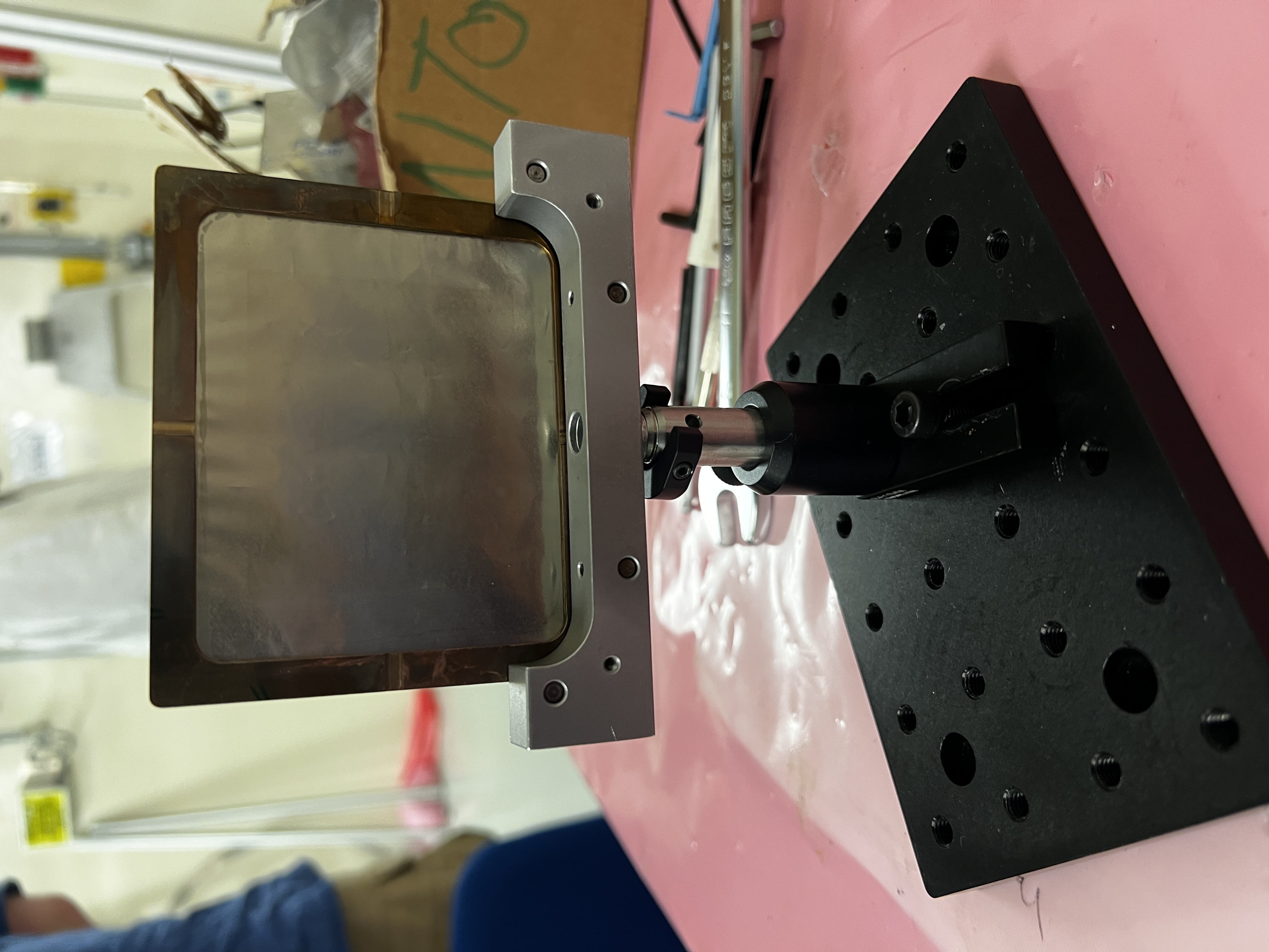
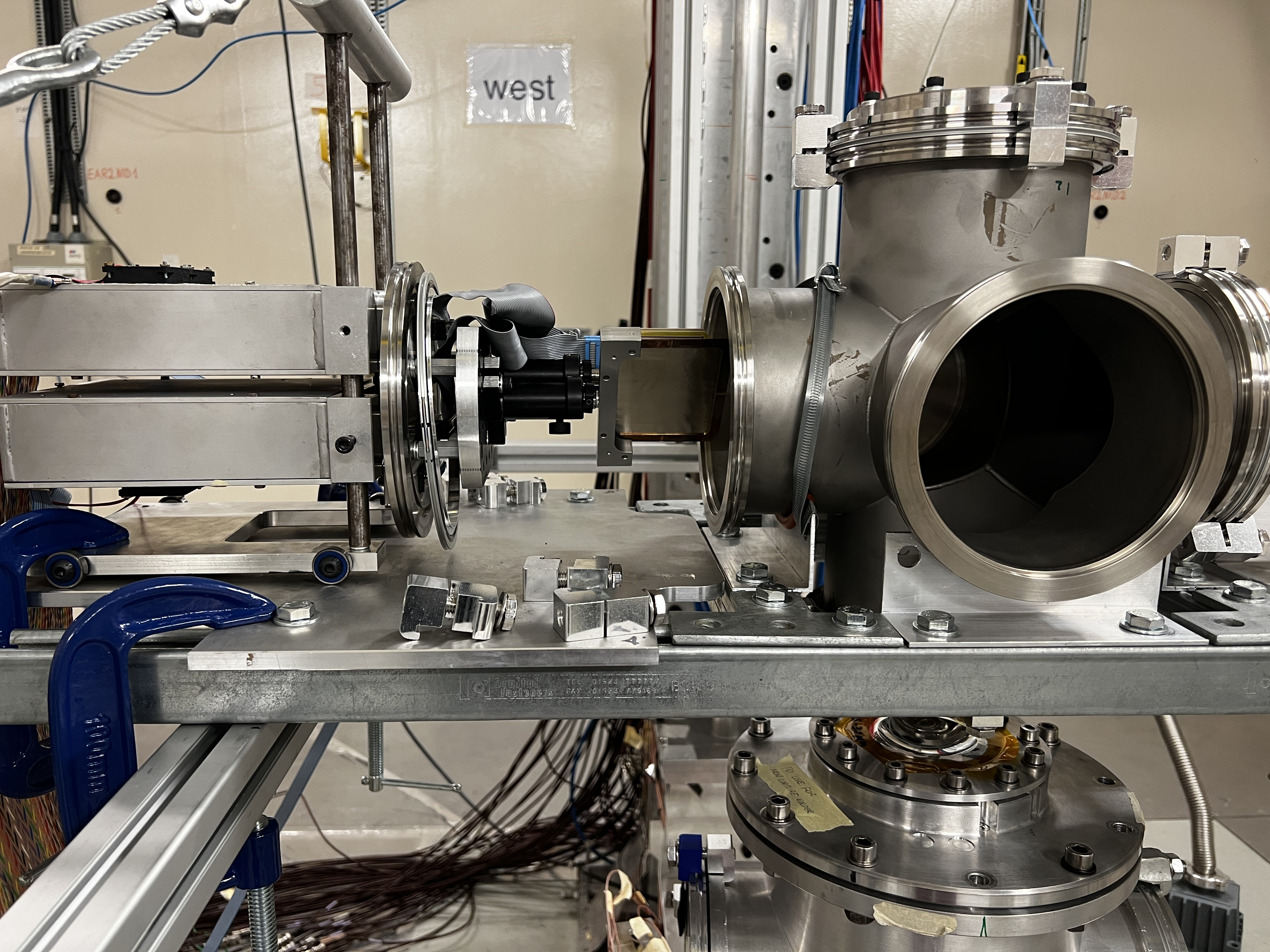
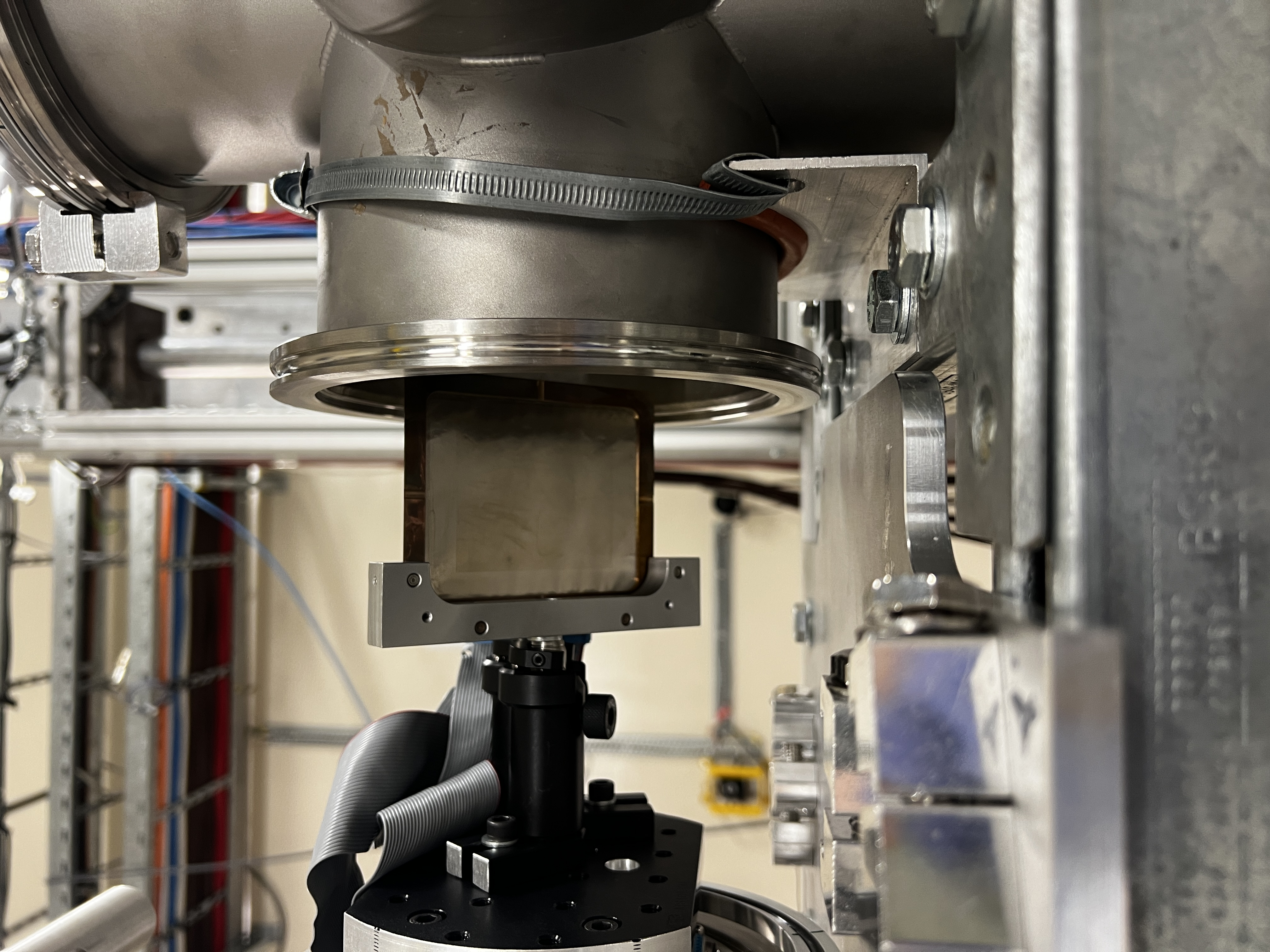
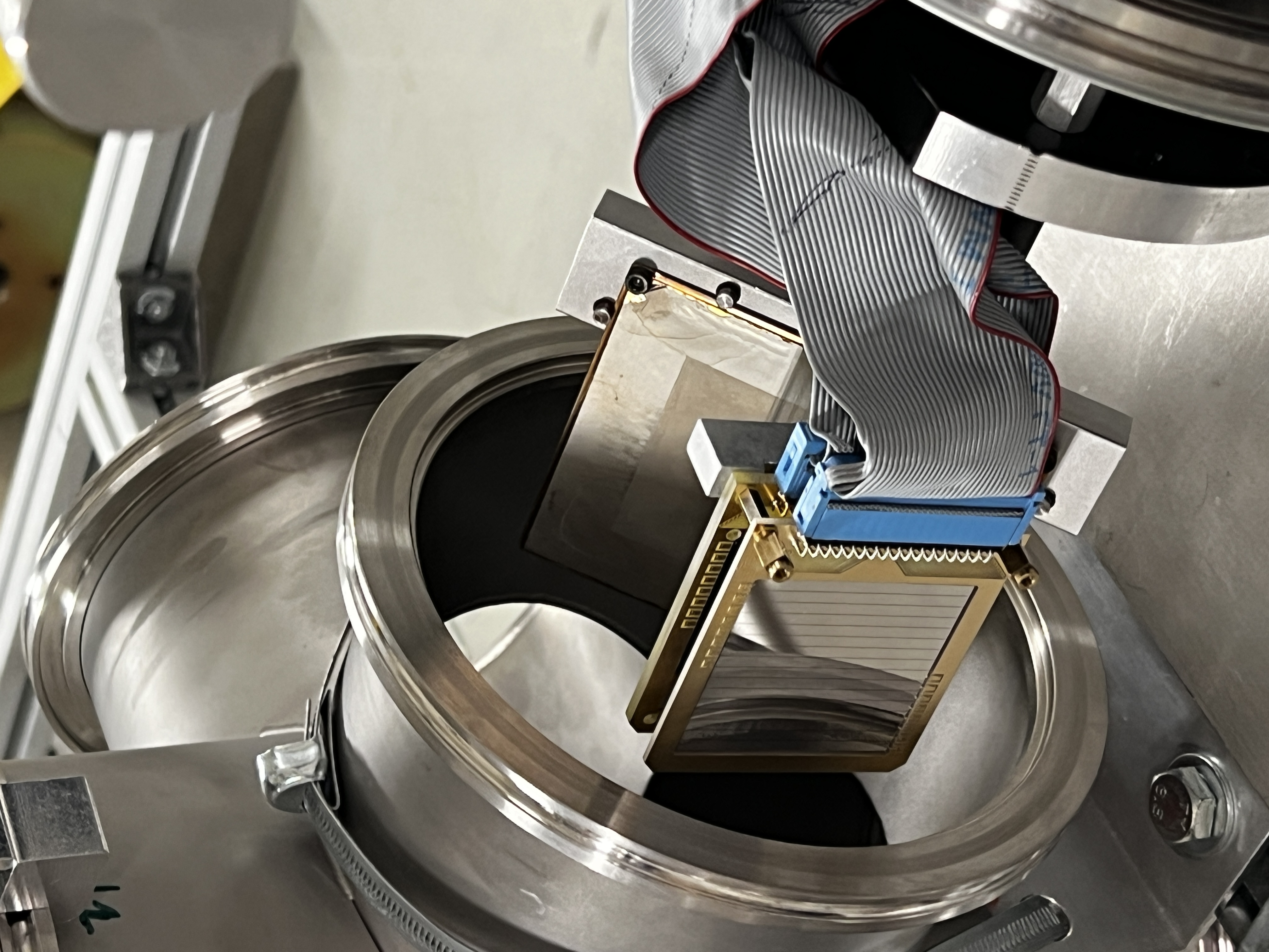
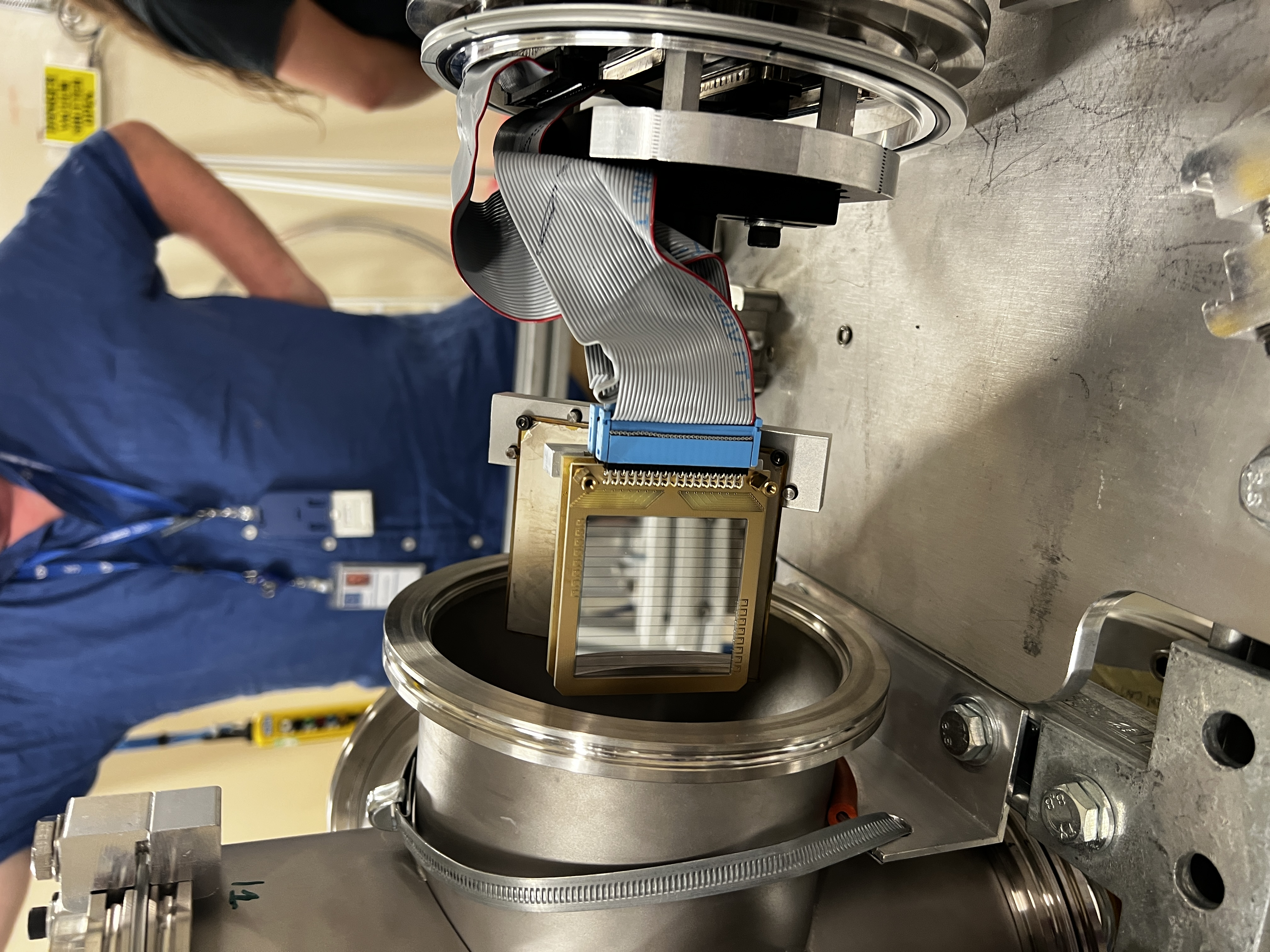
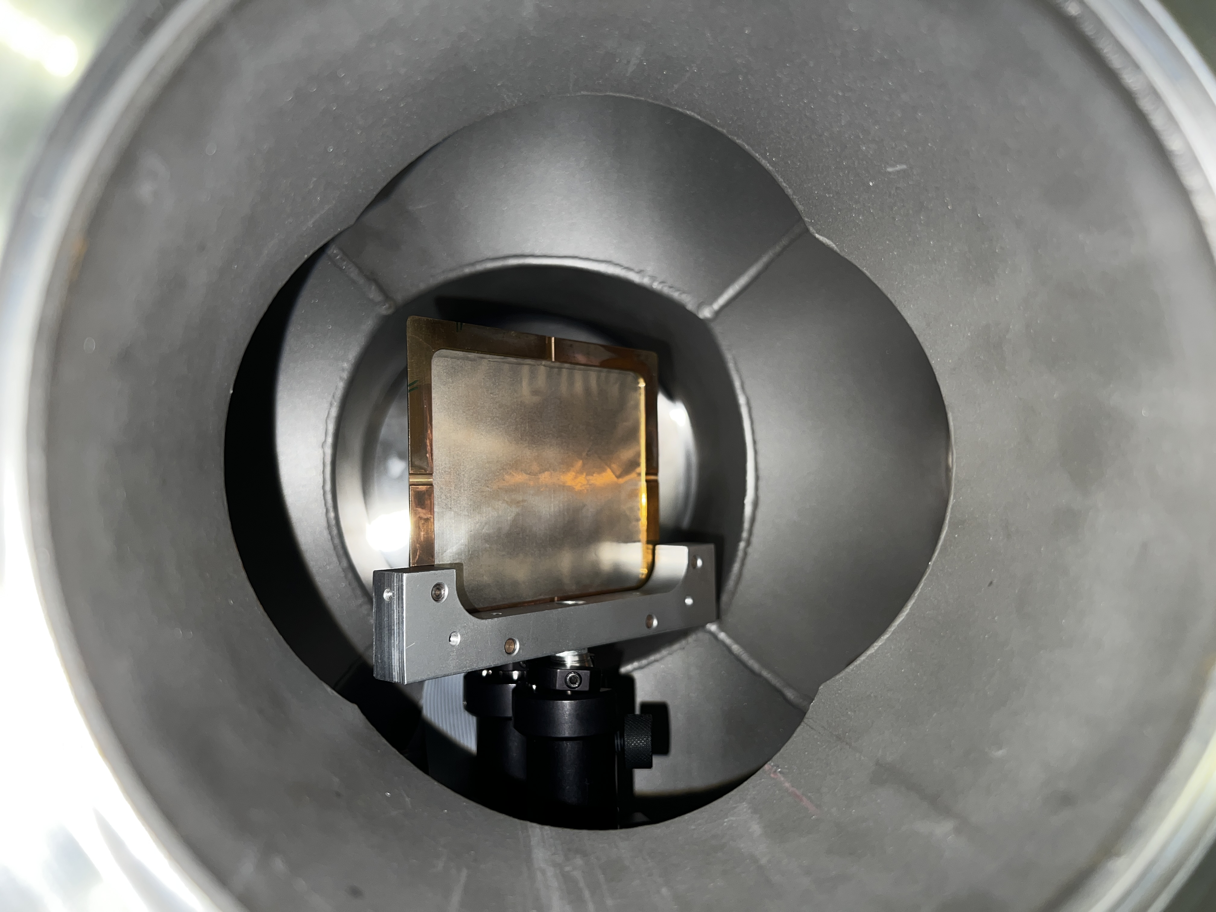
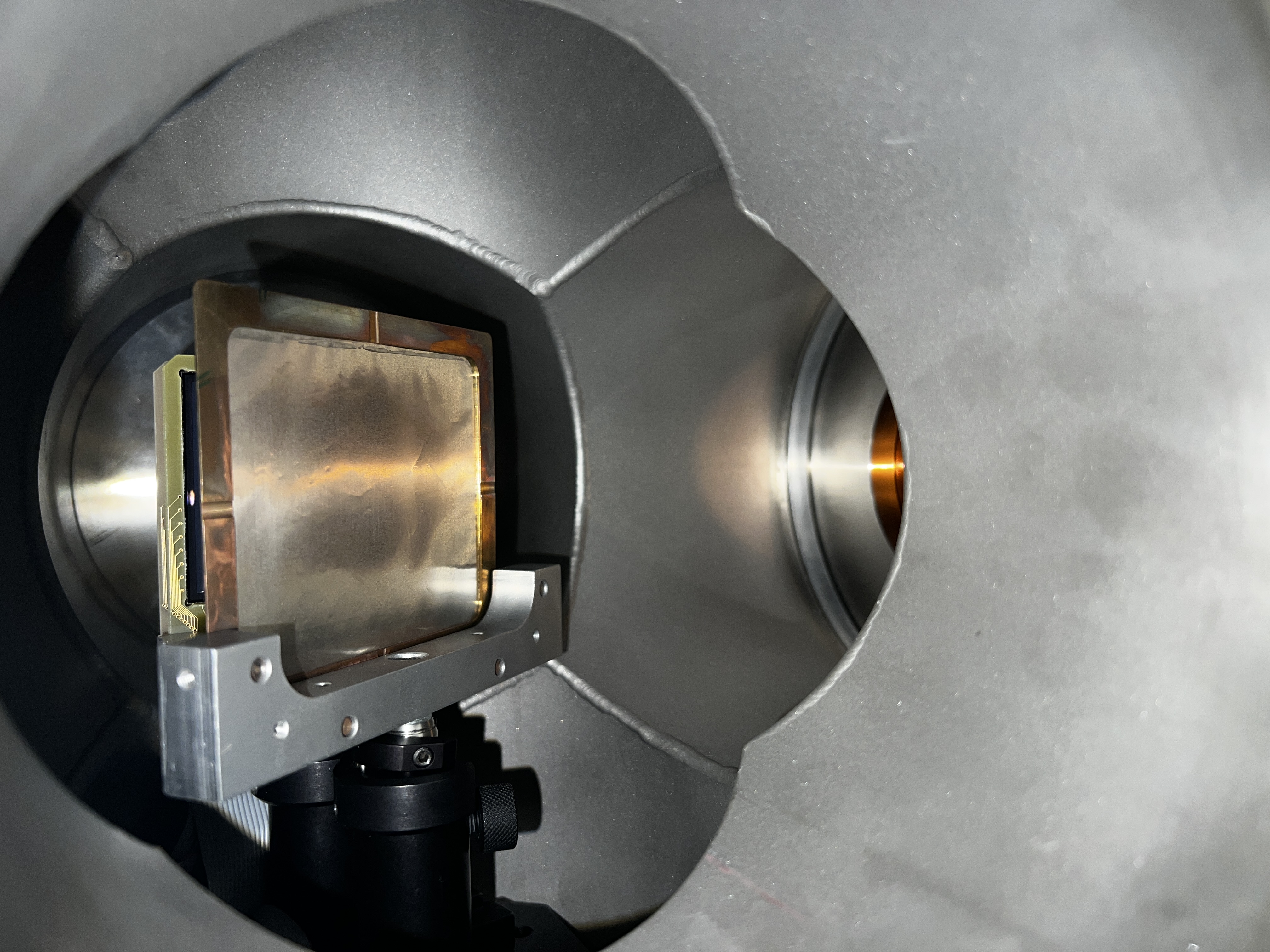
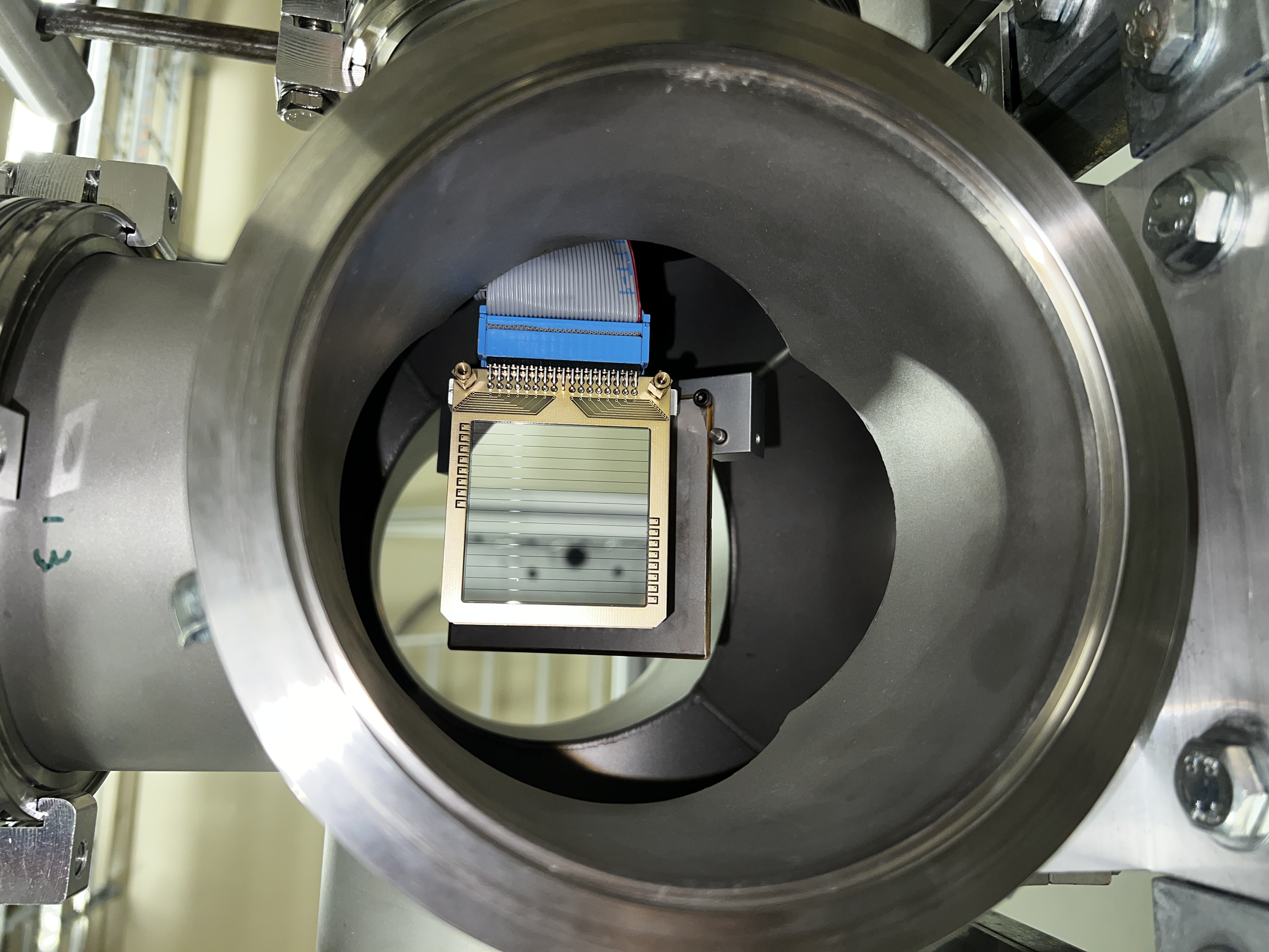
Phtotos of the front & back of the Al target and what it looked like once mounted and in the chamber. |
| Attachment 1: IMG_2860.JPG
|

|
| Attachment 2: IMG_2862.JPG
|

|
| Attachment 3: IMG_2867.JPG
|

|
| Attachment 4: IMG_2868.JPG
|
|
| Attachment 5: IMG_2874.JPG
|
|
| Attachment 6: IMG_2875.JPG
|

|
| Attachment 7: IMG_2877.JPG
|
|
| Attachment 8: IMG_2879.JPG
|

|
| Attachment 9: IMG_2880.JPG
|
|
| Attachment 10: IMG_2882.JPG
|

|
| Attachment 11: IMG_2884.JPG
|
|
| Attachment 12: IMG_2896.JPG
|
|
| Attachment 13: IMG_2897.JPG
|
|
| Attachment 14: IMG_2903.JPG
|
|
| Attachment 15: Al26_Target_Above.JPG
|

|
|
52
|
Thu Aug 10 16:11:57 2023 |
TD, NS, AR | Noise |
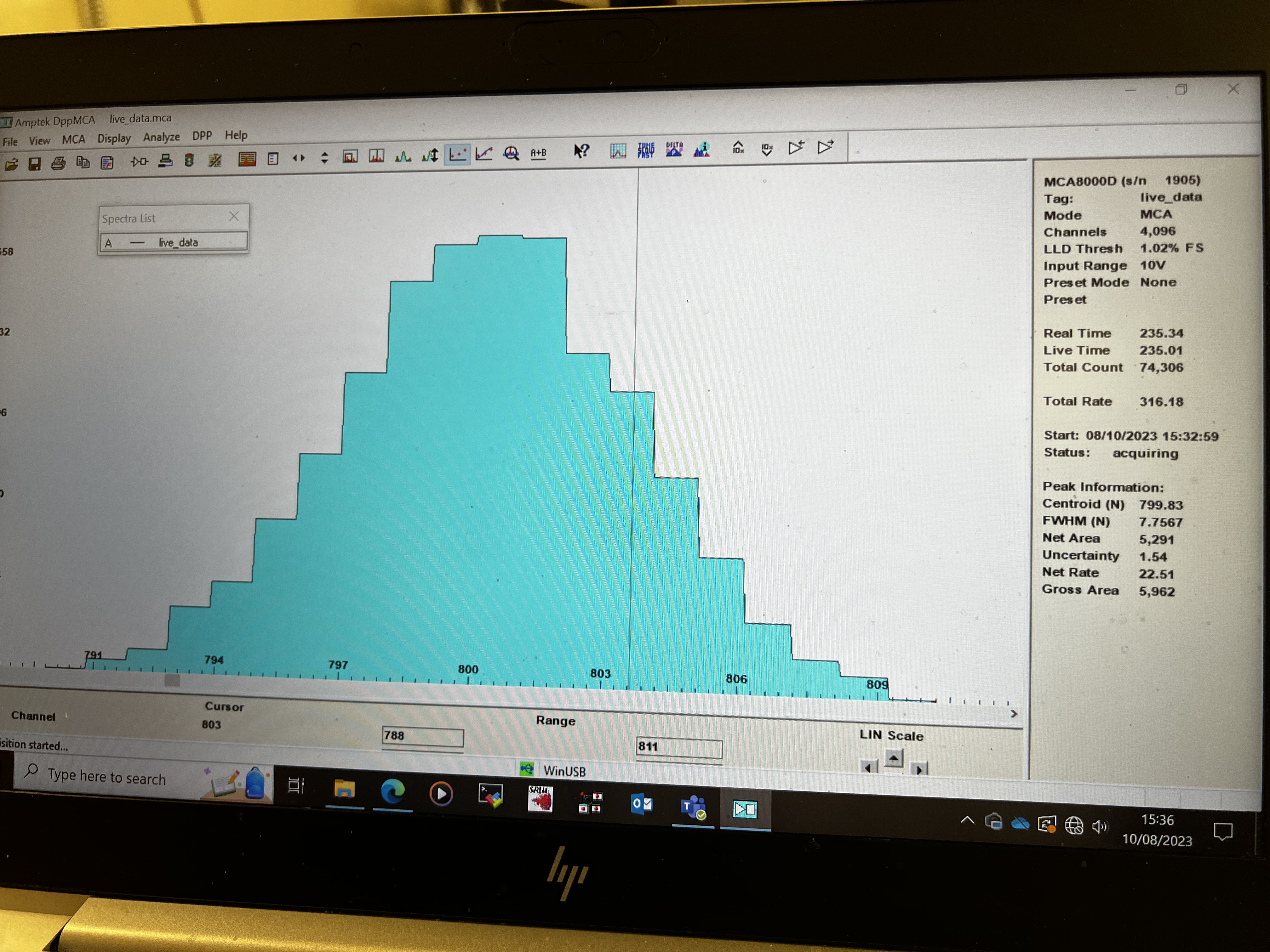
Observe c. 2mV p to p noise with DSO ( Z_in = 50 Ohm ) c. 60us period with HF structure. DSO connected to junction box via 34-way IDC - 16x Lemo-00 adaptor.

Origin of noise upstream of 4x34-way to 8x16-way Junction Box. Not microphonics from Edwards RV5 Rotary Pump.
No change observed with simple ground connections between NIM bin/+/-15V PSU/Junction Box and MSL type W1 preamplifier units/vacuum chamber/support assembly.


Estimate of electronic noise

Pulser BNC PB-5

Amplitude 0.5V
Attenuation x1
Decay time 1ms
Frequency 50Hz

Preamplifier RAL108
Output impedance 100 Ohm
Sensitivity 20mV/MeV ( into high Z load ), 6.7mV/MeV ( into 50 Ohm load )

Amplifier EG&G Ortec 571
Input terminated by 50 Ohm
Gain x1 (internal) x 1.0 (fine gain) x 50 (coarse gain ) = 50
Shaping time 0.5us

MCA Amptek 8000D
Input FSR 10V
12 bit ADC


Nominal gain = 6.7mV/MeV x 50 = 335mV/MeV

12 bit ADC input FSR = 10V / 0.335V/MeV = 29.85MeV FSR or 7.3keV/channel


dE p+n junction strip # 4 ( of 0-15 )

pulser peak centroid = 799.8 ch
pulser peak width = 7.8 ch FWHM = 57 keV FWHM


E p+n junction strip # 4 ( of 0-15 )

pulser peak centroid = 864.8ch
pulser peak width = 3.5 ch FWHM = 26 keV FWHM


E n+n Ohmic strip # 4 ( of 0-15 )

pulser peak centroid = 913.0 ch
pulser peak width = 5.3 ch FWHM = 39 keV FWHM


Noise estimates are probably accurate to c. 10% level. |
| Attachment 1: 20230810_162959.JPG
|

|
| Attachment 2: IMG_2906.jpeg
|
|
| Attachment 3: 20230810_164219.JPG
|

|
|
51
|
Thu Aug 10 11:30:32 2023 |
Nikolay Sosnin | Silicons and LiF3+Gafchromic Target |
|
| Attachment 1: EDET_150um_Box.JPG
|

|
| Attachment 2: EDET_150um.JPG
|

|
| Attachment 3: EDET_ID.JPG
|
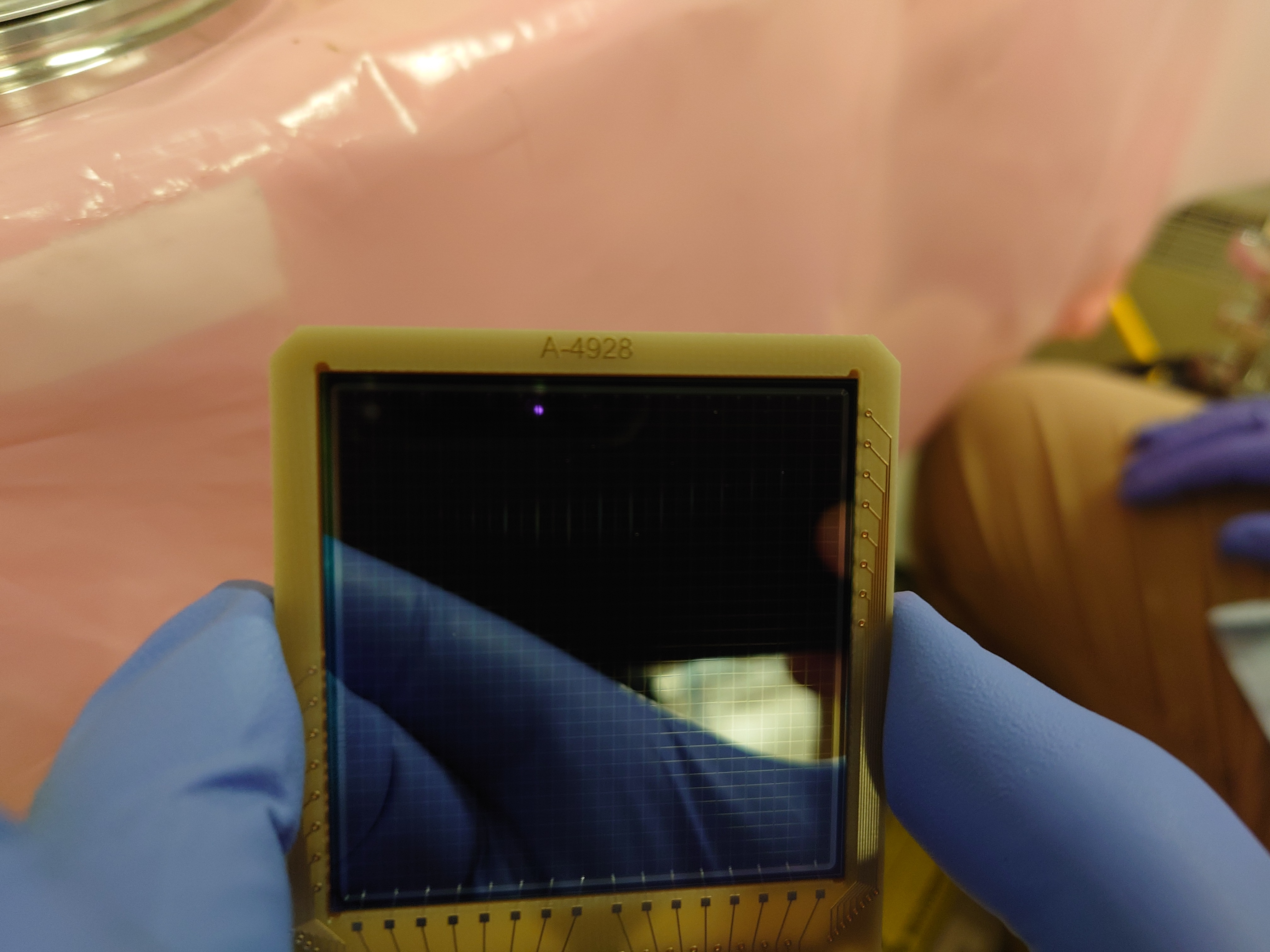
|
| Attachment 4: DEED_20um_Box.JPG
|
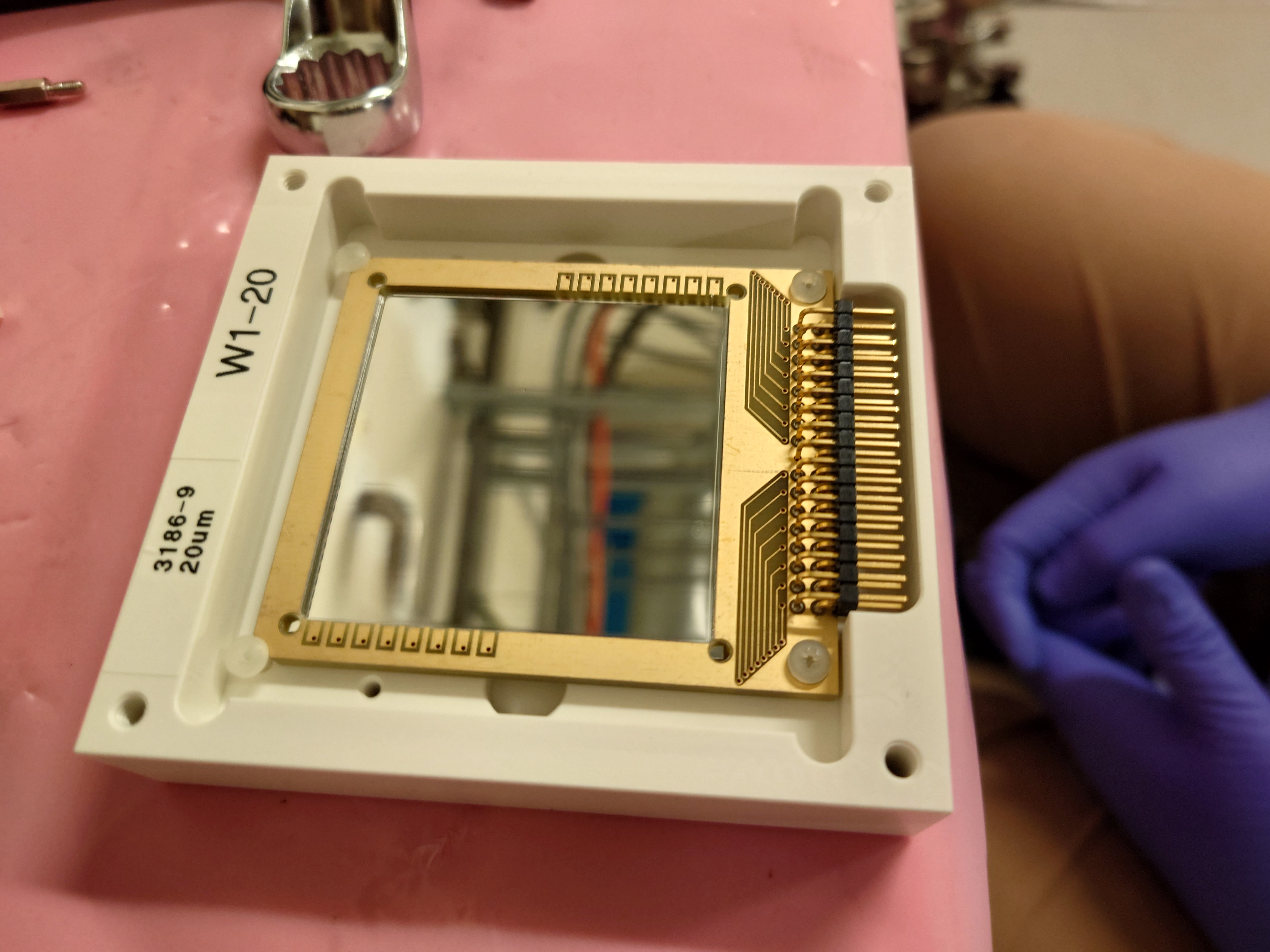
|
| Attachment 5: LiF3_Gafchrmoic_Target_Mounted.JPG
|
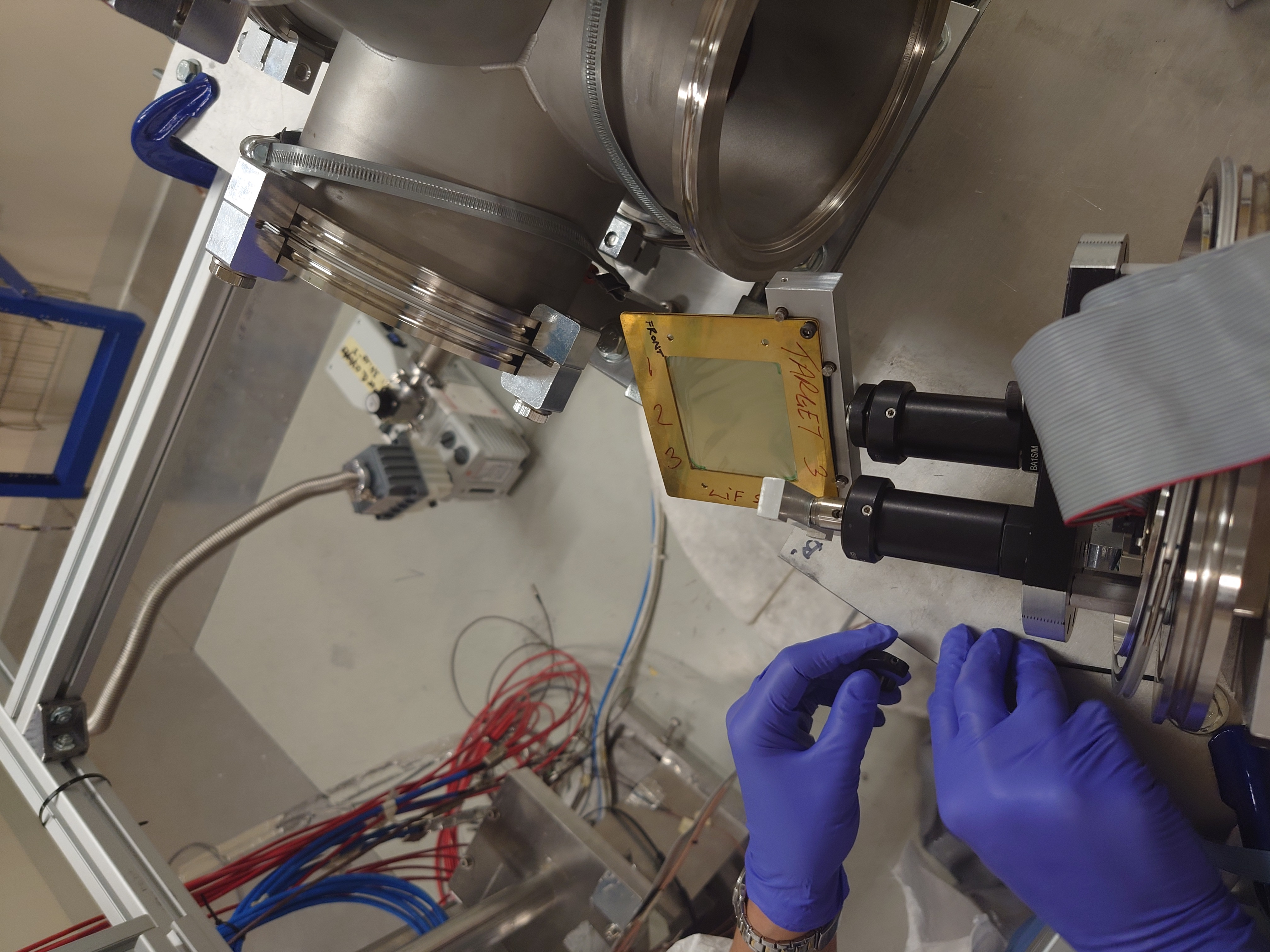
|
| Attachment 6: LiF3_Gafchromic_Side.JPG
|
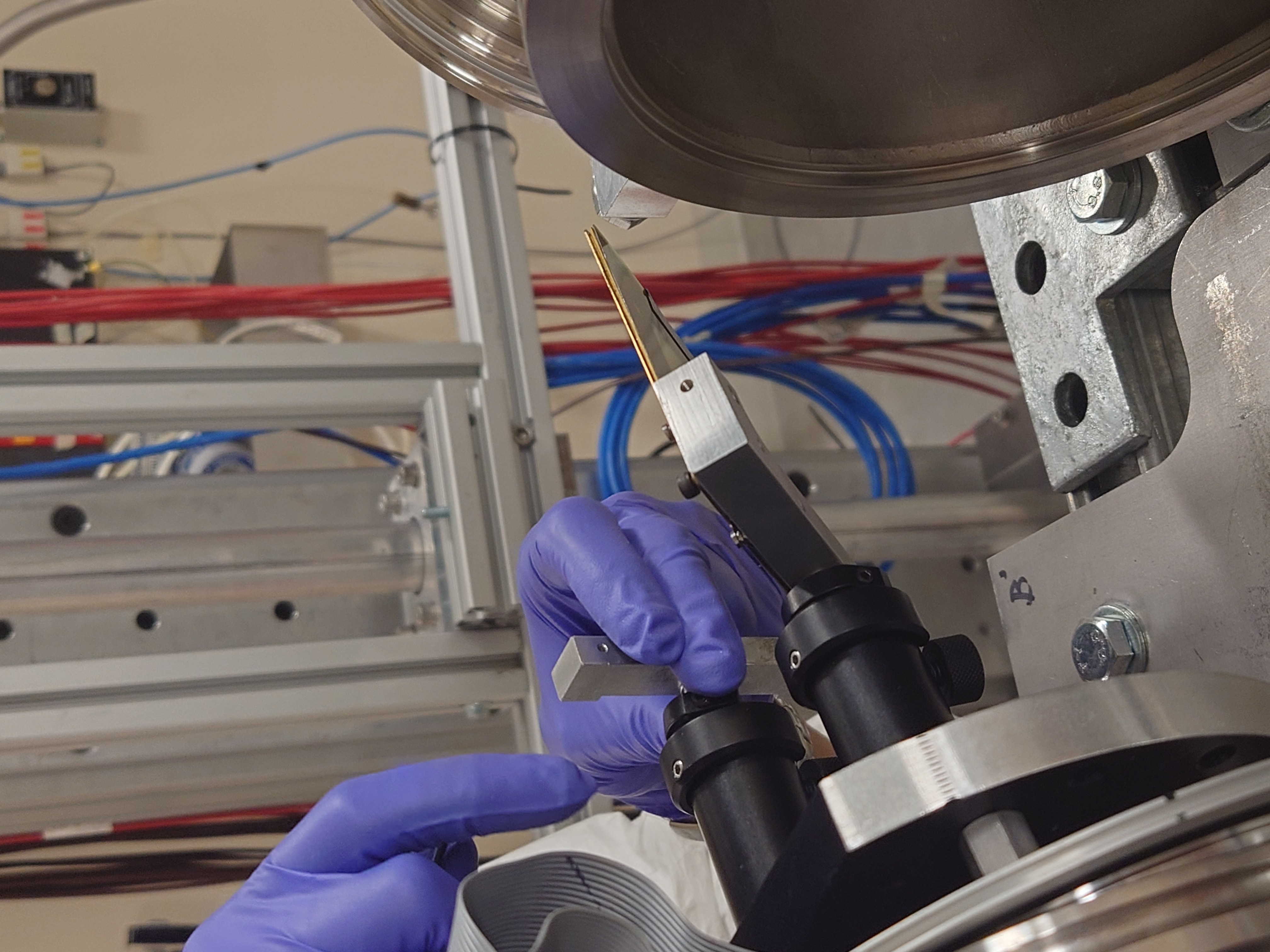
|
| Attachment 7: LiF3_Gafchromic_Front.JPG
|

|
| Attachment 8: Detector_Mount_and_LiF3.JPG
|

|
| Attachment 9: Detectors_Mounting.JPG
|

|
| Attachment 10: Detectors_Mounted_DEED.JPG
|

|
| Attachment 11: Detectors_Mounted_EDET.JPG
|
|
| Attachment 12: Detectors_and_LiF3_Gafchrmoic_TestPosition.JPG
|

|
| Attachment 13: Detectors_and_LiF3_Gafchrmoic_TestPosition_Back.JPG
|
|
| Attachment 14: Detectors_and_LiF3_Gafchrmoic_TestPosition_Below.JPG
|
|
| Attachment 15: Detectors_and_LiF3_Gafchrmoic_TestPosition_Above.JPG
|
|
| Attachment 16: Detectors_and_LiF3_Gafchrmoic_TestPosition_Tilt.JPG
|
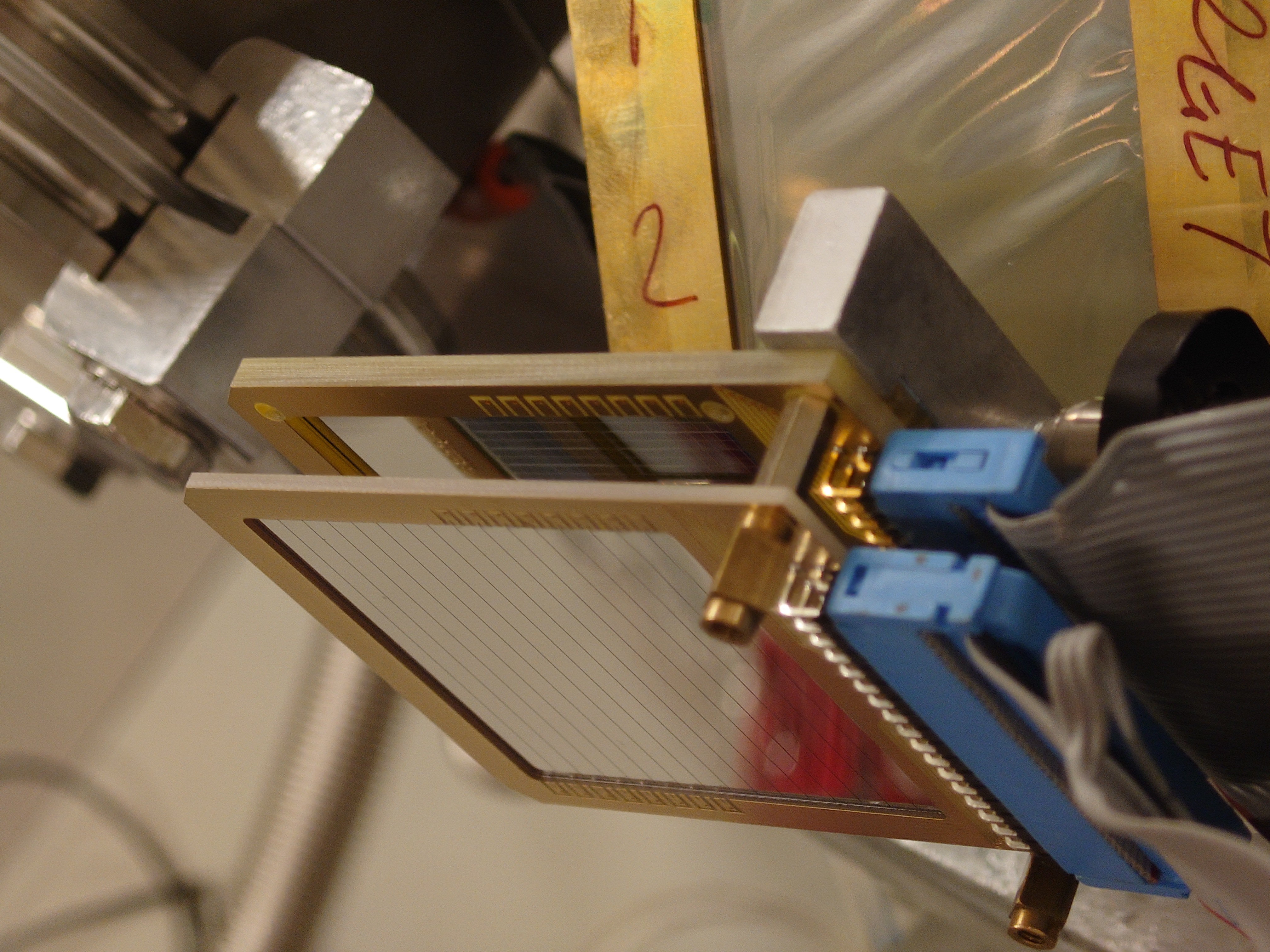
|
| Attachment 17: Detectors_and_LiF3_Gafchrmoic_TestPosition_Front.JPG
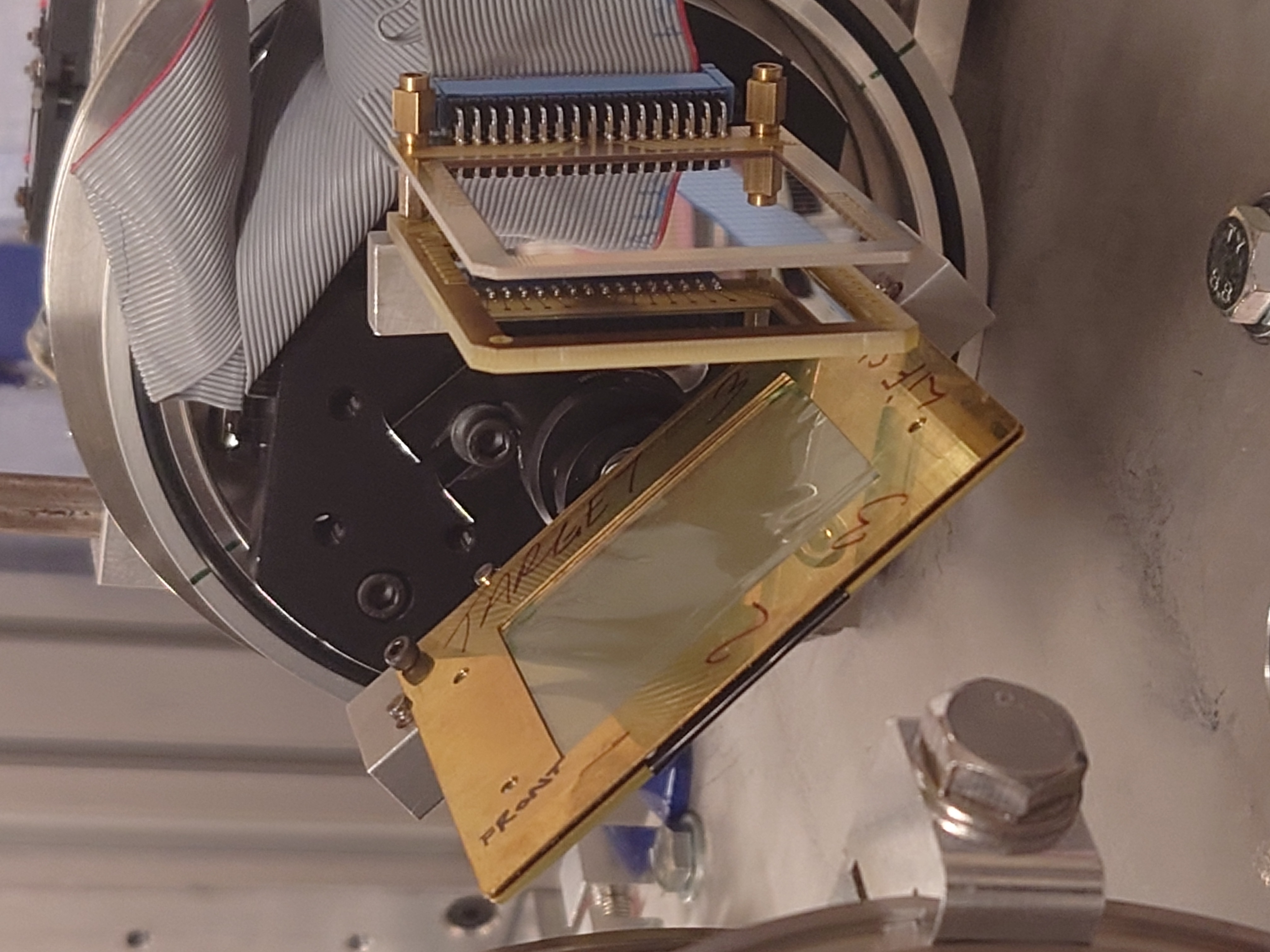
|
|
| Attachment 18: Assembly_Insert.JPG
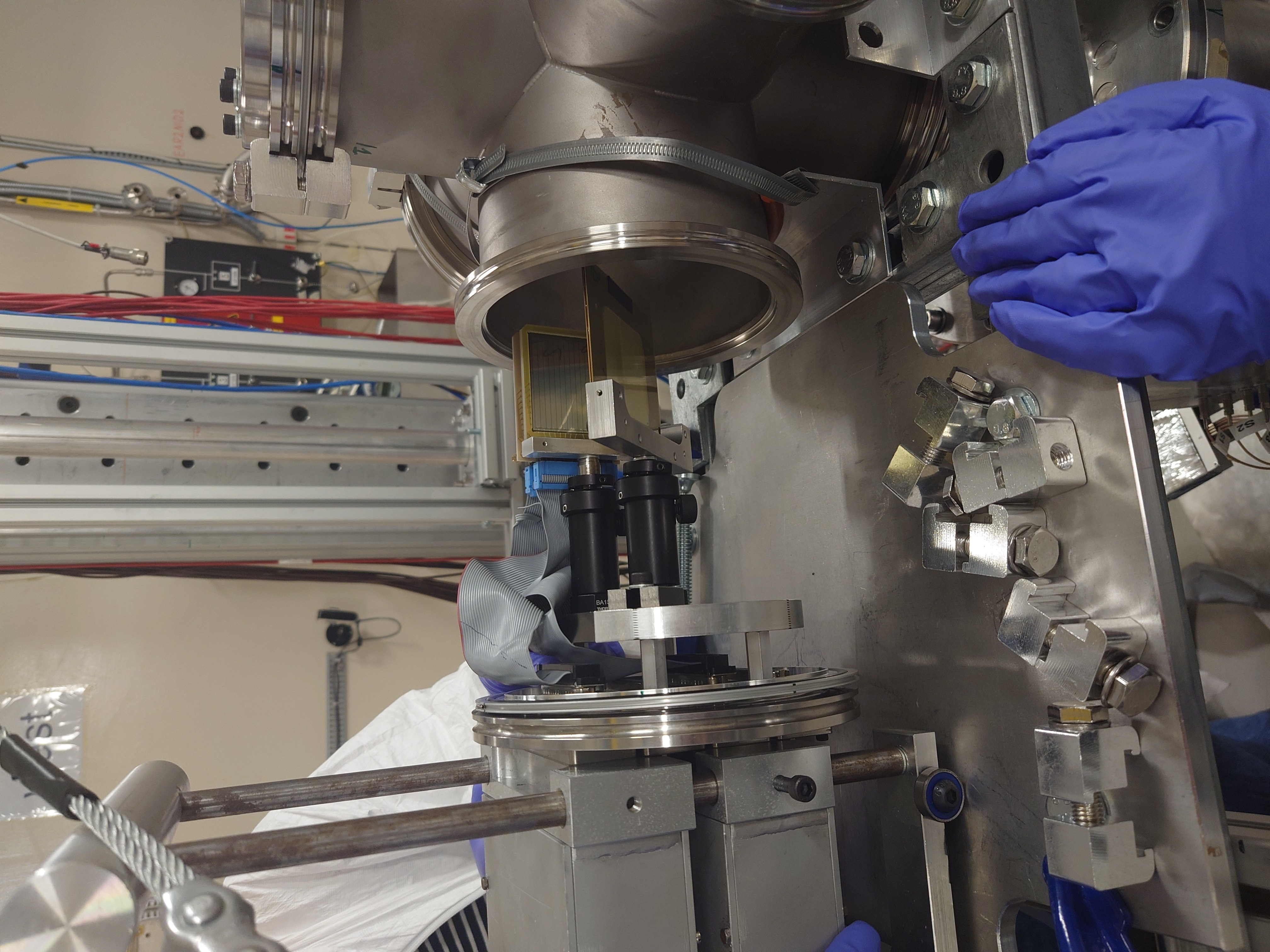
|
|
|
50
|
Thu Aug 10 10:50:15 2023 |
Nikolay Sosnin | Al26 Chamber Cabling/Vacuum/NIM |
|
| Attachment 1: Vacuum_Reading.JPG
|

|
| Attachment 2: Pulser_Settings3.JPG
|
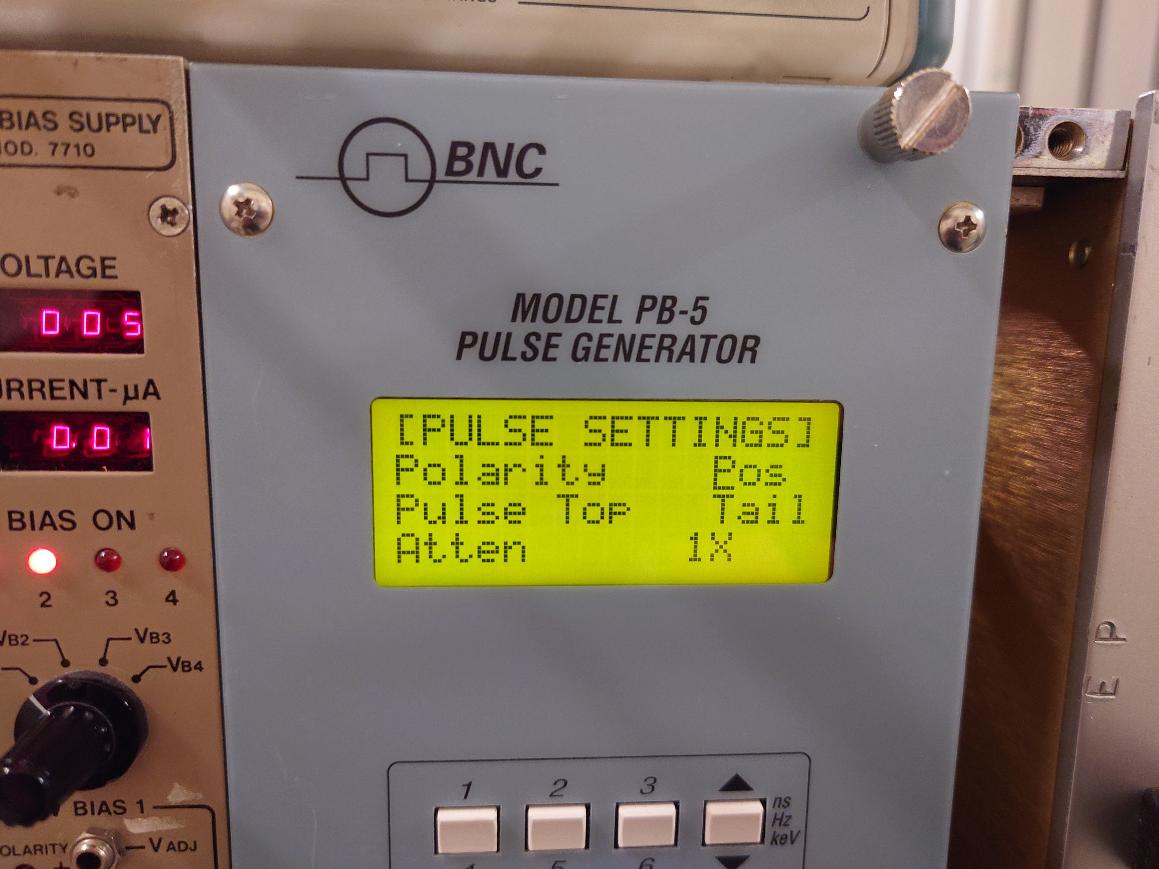
|
| Attachment 3: Pulser_Settings2.JPG
|

|
| Attachment 4: NIM_Bin.JPG
|

|
| Attachment 5: Currents.JPG
|
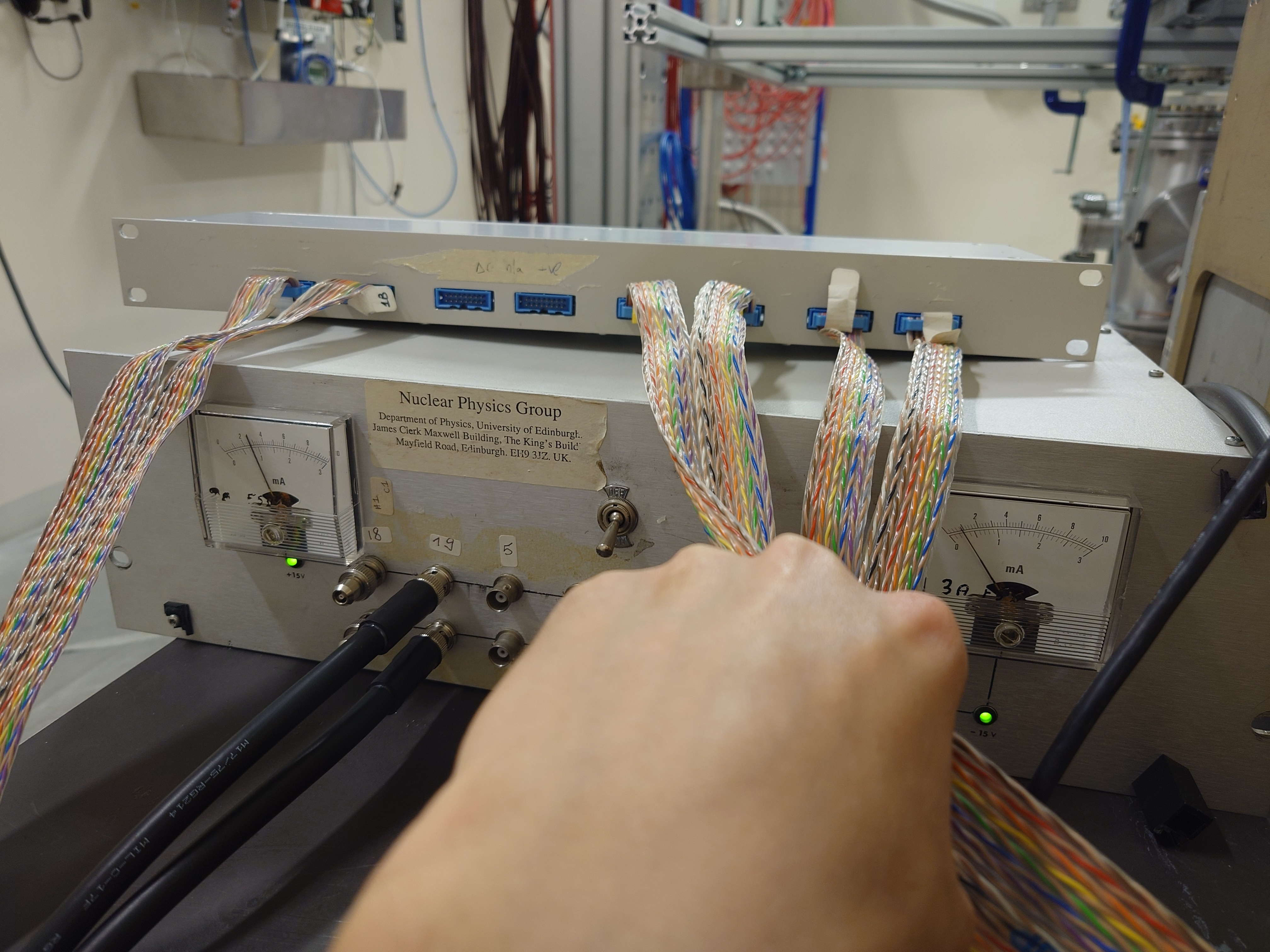
|
| Attachment 6: Amplifier_Settings.JPG
|
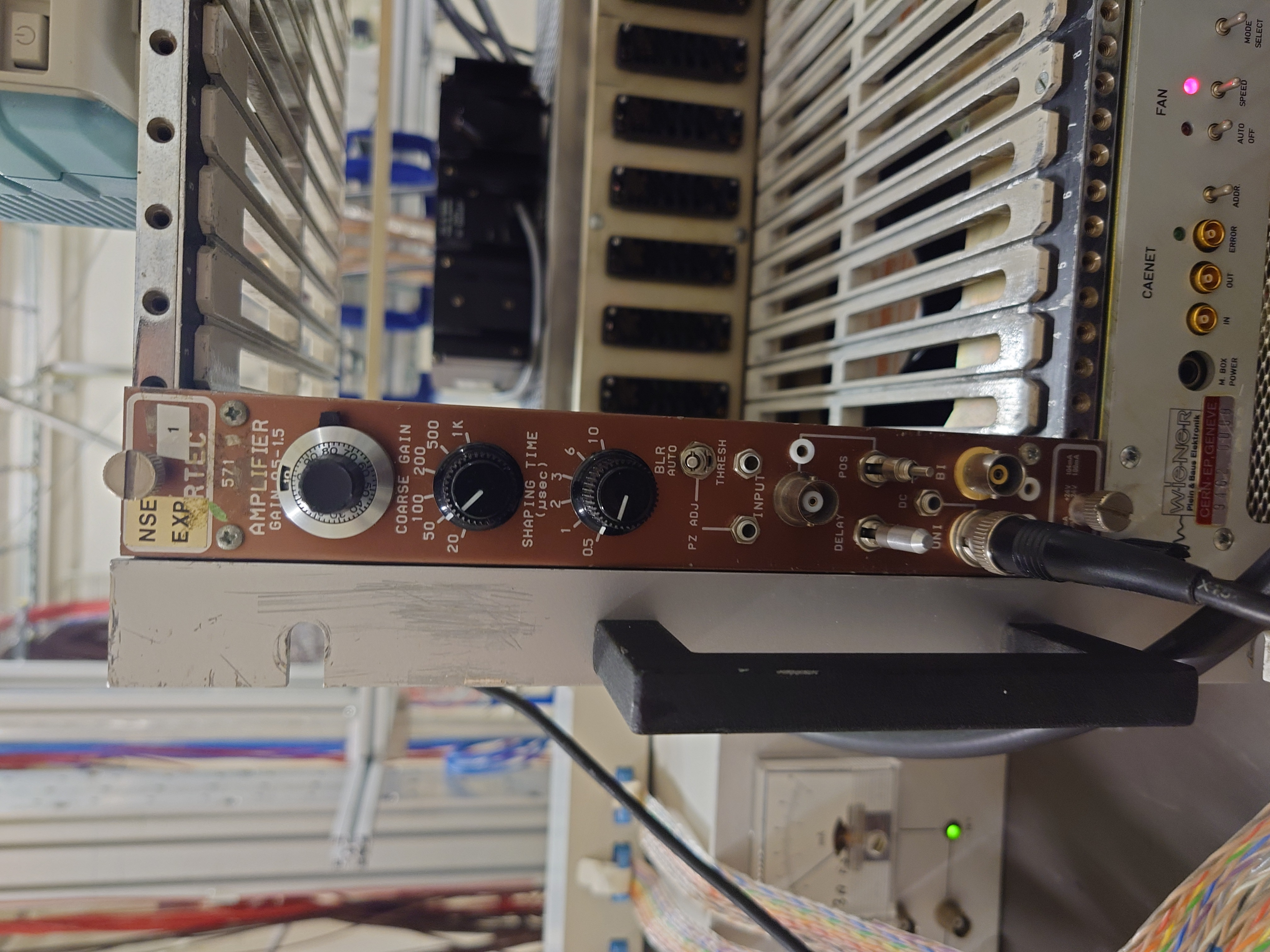
|
| Attachment 7: HV_EDET.JPG
|
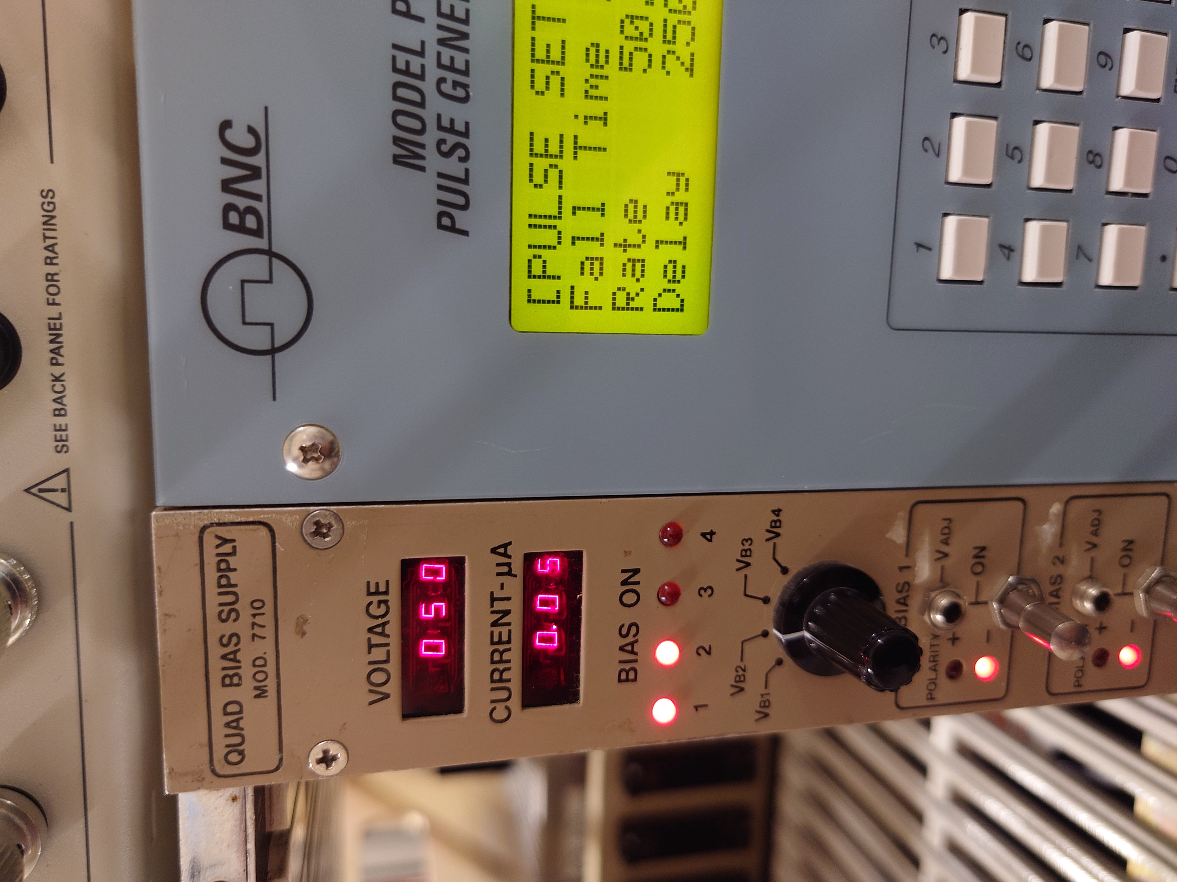
|
| Attachment 8: HV_DEED.JPG
|
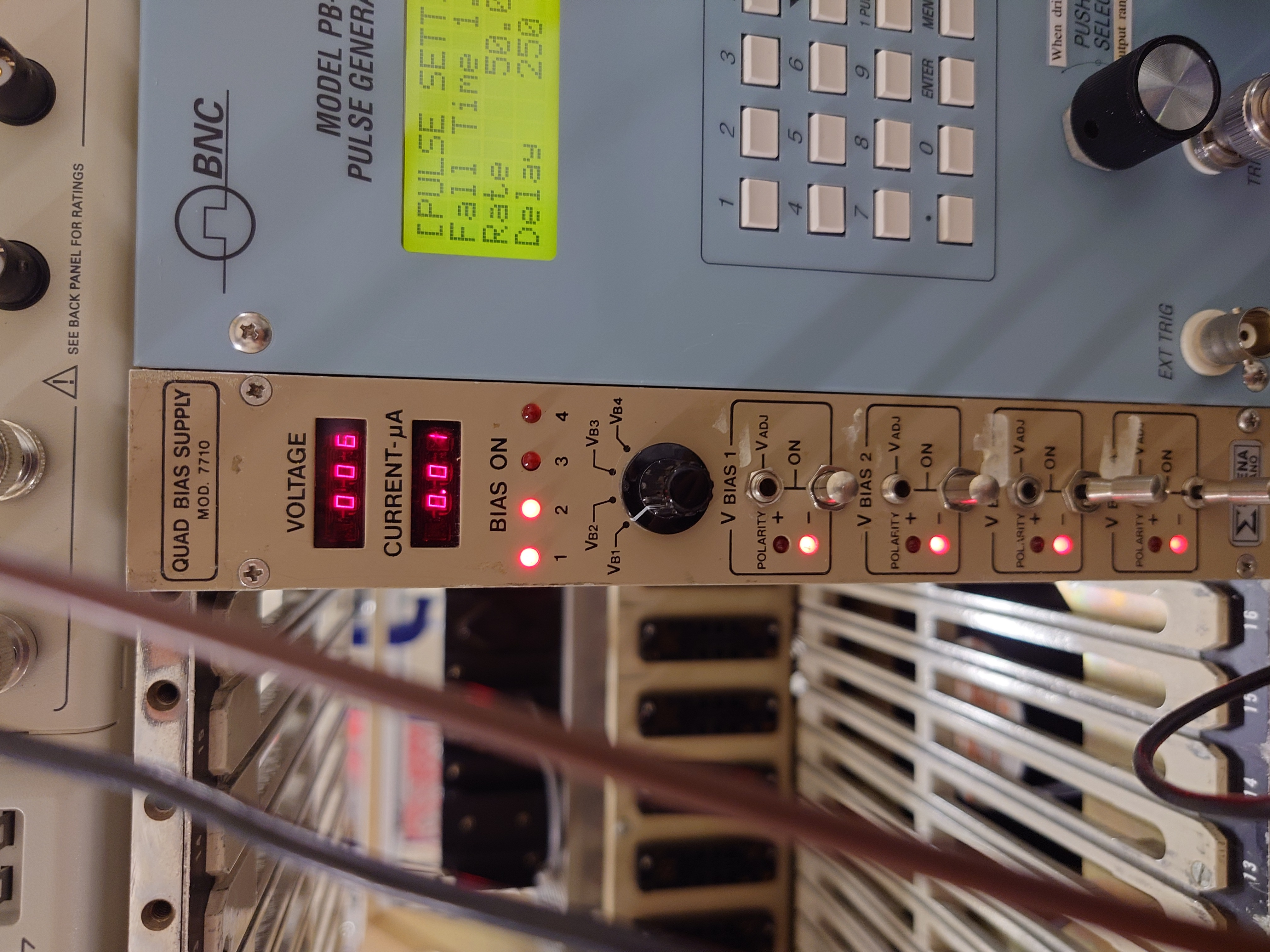
|
| Attachment 9: Pulser_Settings1.JPG
|

|
| Attachment 10: Cables_Full_View.JPG
|
|
| Attachment 11: Preamp_Cables.JPG
|
|
| Attachment 12: BNC_Converters.JPG
|

|
| Attachment 13: DAQ_Cable_Connection_BNC.JPG
|

|
| Attachment 14: Ribbon_Cables_DAQ.JPG
|
|
| Attachment 15: Ribbon_Cables_DAQ.JPG
|

|
| Attachment 16: NIM_Setup_Full.JPG
|

|
| Attachment 17: Vacuum_Pump.JPG
|

|
| Attachment 18: Vacuum_Pump_Exhaust.JPG
|
|
| Attachment 19: Vacuum_Pump_Attachment.JPG
|

|
| Attachment 20: Vacuum_Gauge.JPG
|
|
| Attachment 21: Vacuum_Valve_Lid.JPG
|

|
| Attachment 22: Ribbon_Cables_Back.JPG
|
|
| Attachment 23: Ribbon_Cables.JPG
|

|
|
49
|
Thu Aug 10 10:05:48 2023 |
CLW | Gafchromics Foil |
Gafchromics foil was mounted on empty brass frame back to back with Li sample
Neutron beam goes well through the sample. Centered ~1 cm from sample center. Conclusion: no changes needed (too risky to make it worse and it is ok now) |
| Attachment 1: 20230809_165433.jpg
|

|
| Attachment 2: 20230810_085457.jpg
|

|
| Attachment 3: 20230809_165436.jpg
|

|
|
48
|
Thu Aug 10 10:04:13 2023 |
CLW | Photos inside chamber Al26 run Aug2023 |
|
| Attachment 1: 20230809_174847.jpg
|

|
| Attachment 2: 20230809_174905.jpg
|
|
| Attachment 3: 20230809_174943.jpg
|
|
| Attachment 4: Empty_Frame_Inside_Front.JPG
|
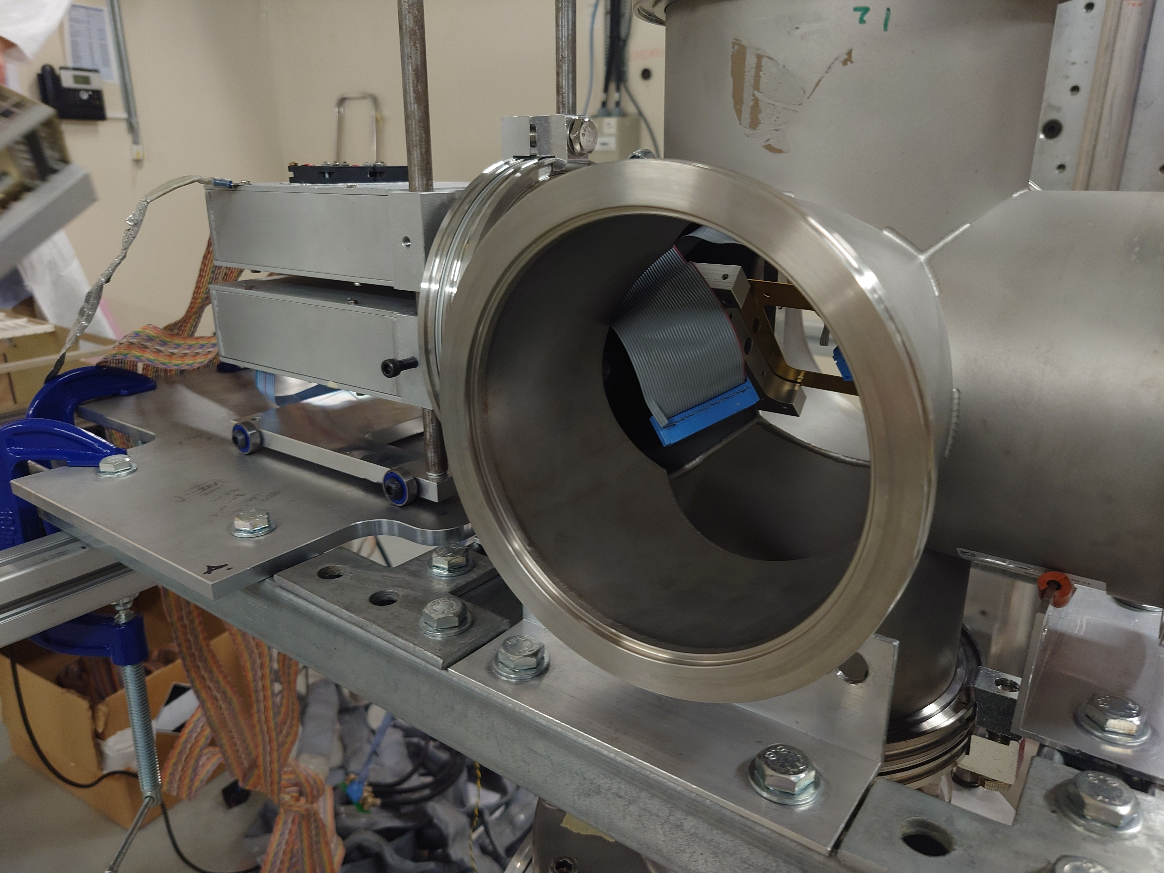
|
| Attachment 5: Empty_Frame_Inside_Sideview.JPG
|

|
| Attachment 6: Empty_Frame_Inside_Back.JPG
|
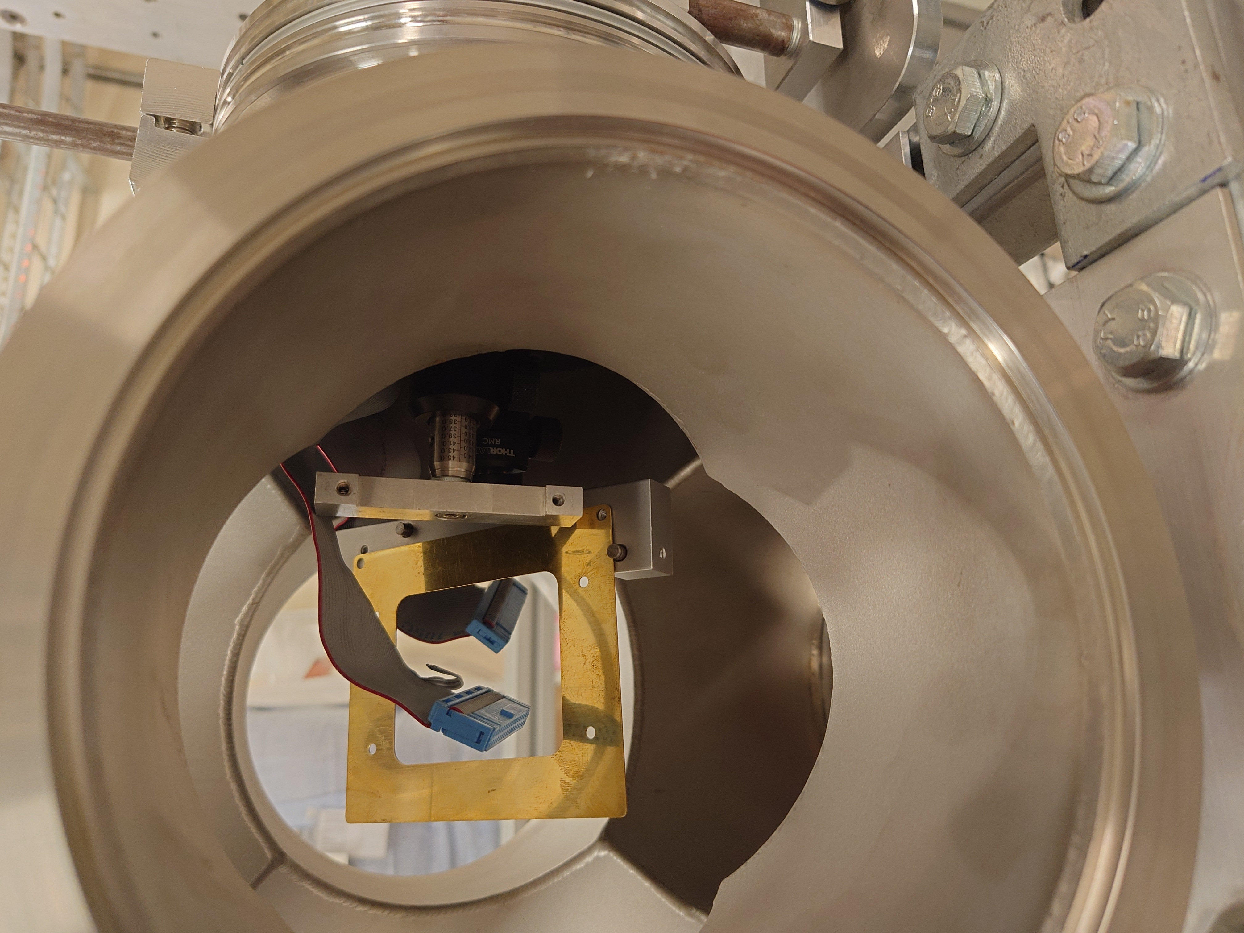
|
| Attachment 7: Assembly_Interior_Back.JPG
|
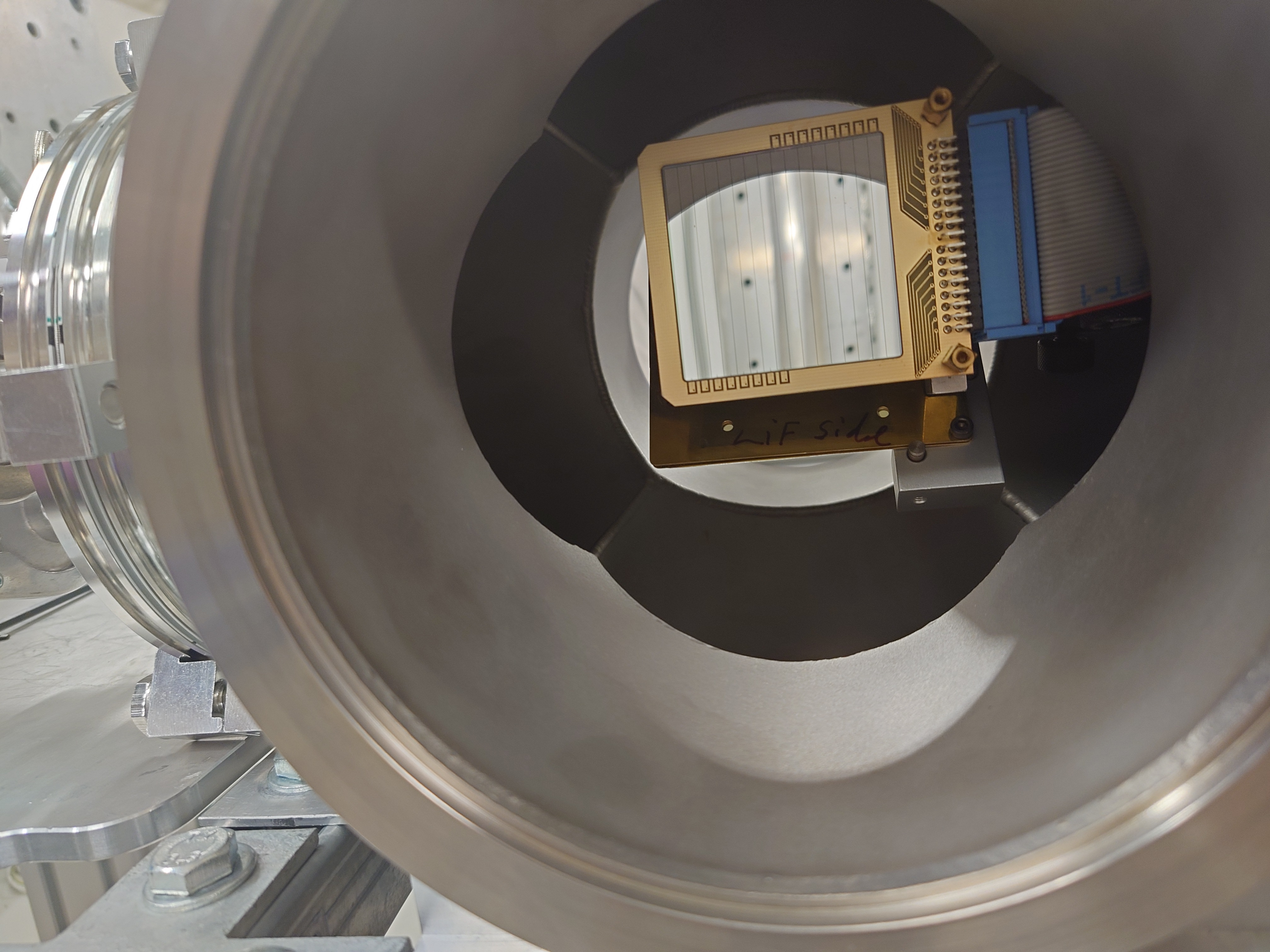
|
| Attachment 8: Assembly_Interior_Front.JPG
|
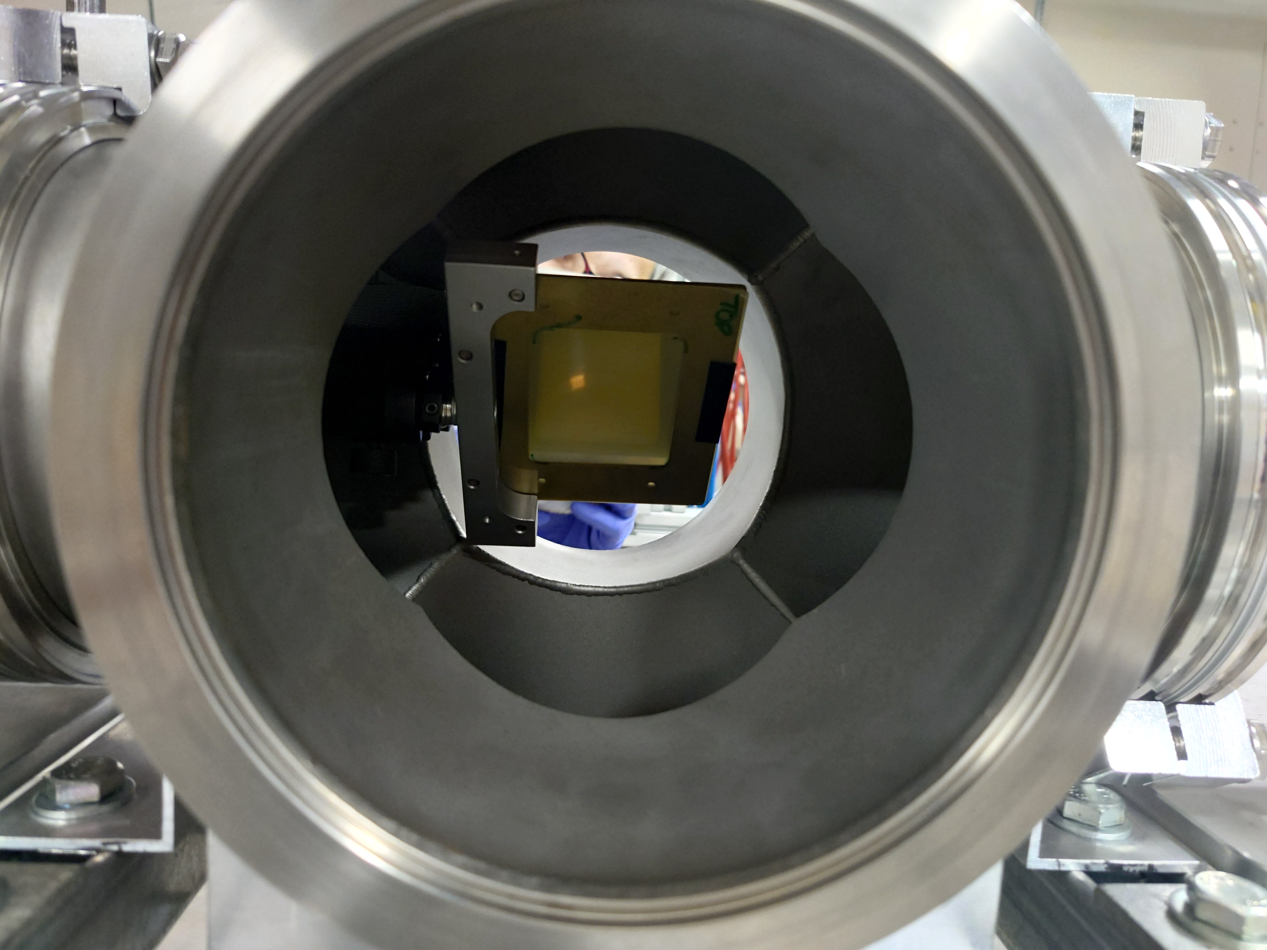
|
|
47
|
Thu Aug 10 09:55:50 2023 |
CLW | Photos of Chamber, Al26 Run Aug23 |
|
| Attachment 1: 20230809_120302.jpg
|

|
| Attachment 2: 20230809_120309.jpg
|

|
| Attachment 3: 20230809_153802.jpg
|

|
| Attachment 4: 20230809_153809.jpg
|

|
| Attachment 5: 20230809_153821.jpg
|
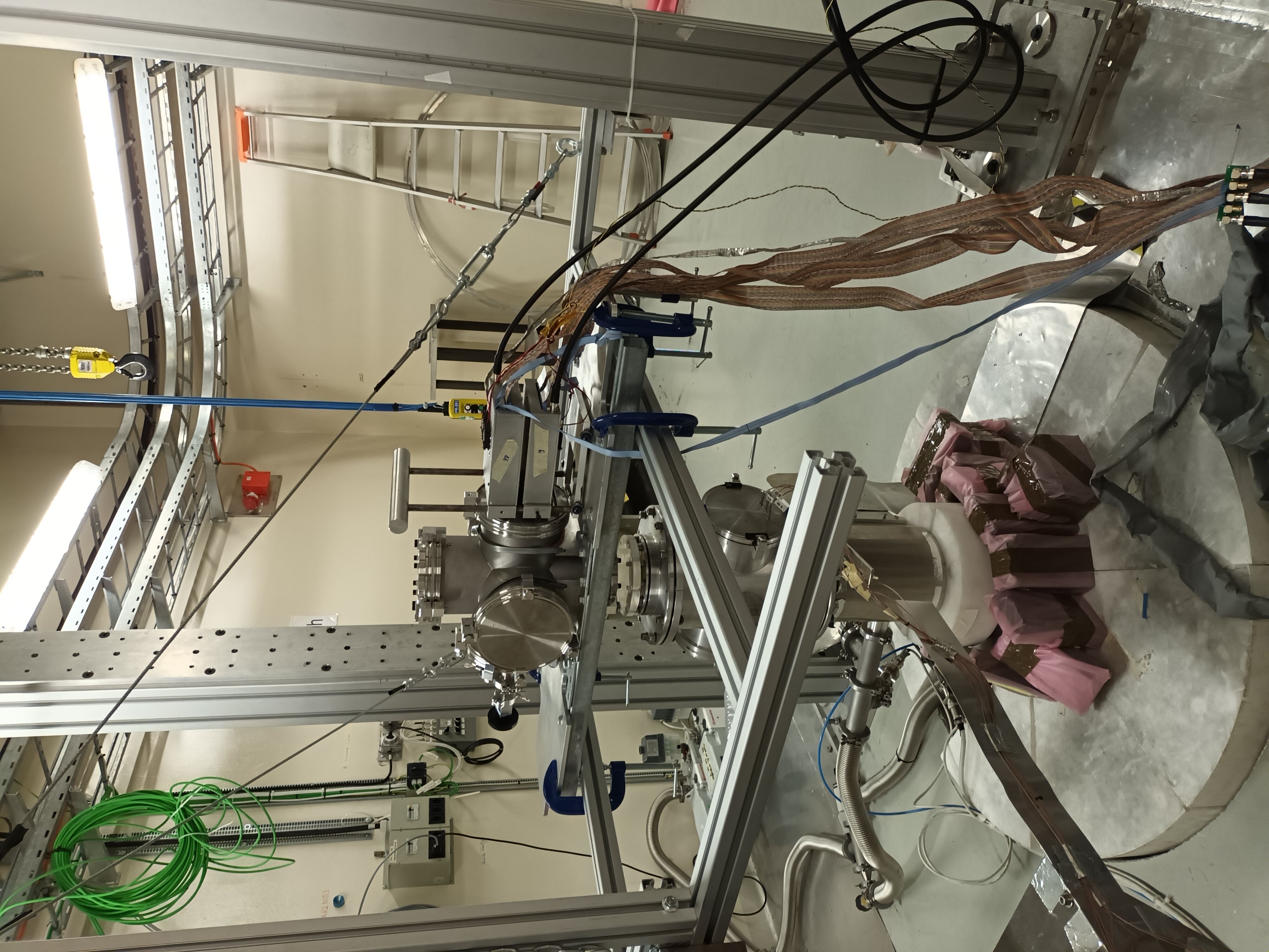
|
| Attachment 6: Beamline_Chamber_Spacing.JPG
|

|
| Attachment 7: Assembled_Setup_Back.JPG
|
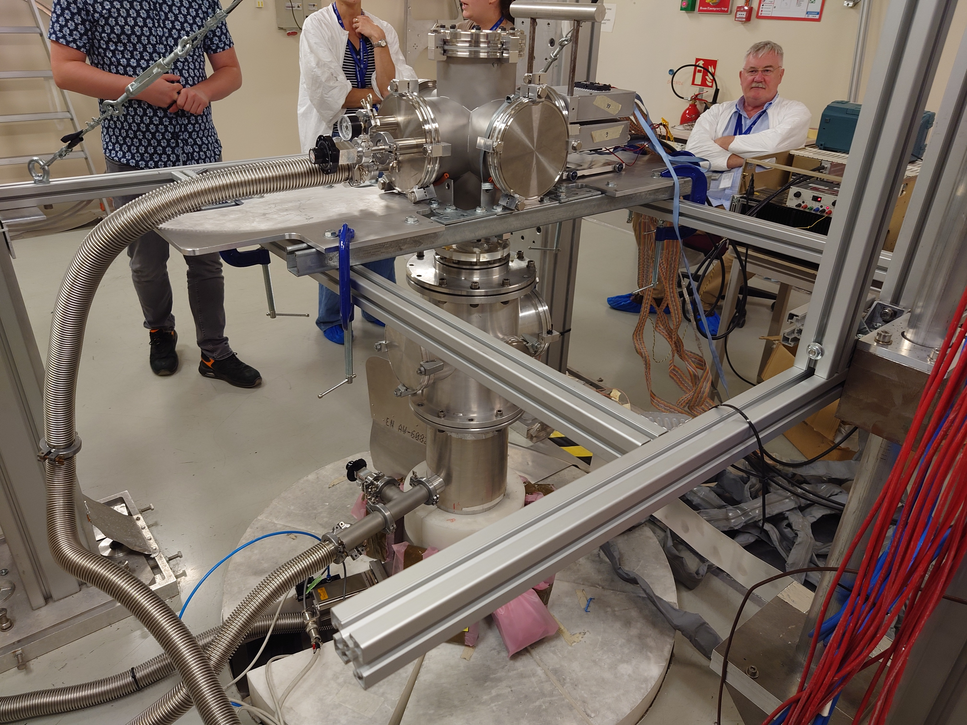
|
| Attachment 8: Assembled_Setup_Back_Zoom.JPG
|
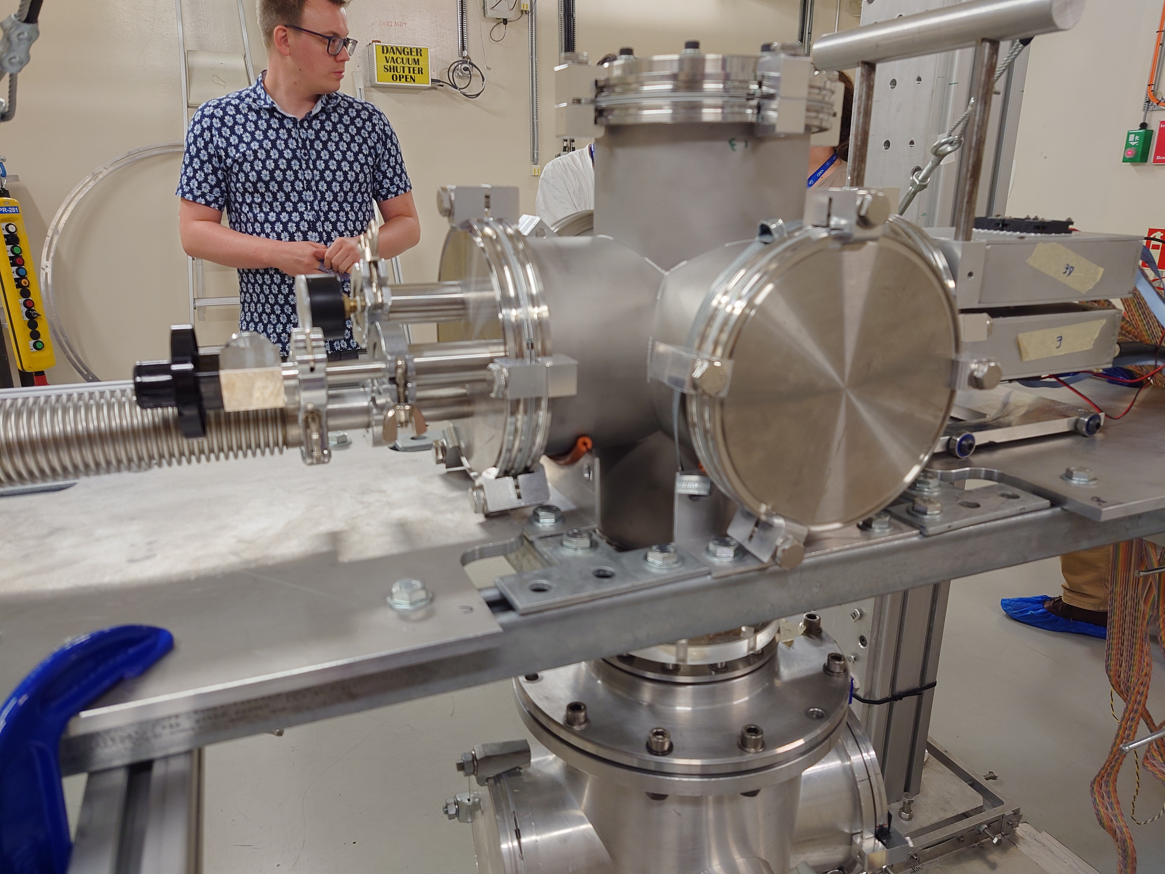
|
| Attachment 9: Final_Assembly_Front.JPG
|

|
| Attachment 10: Mounting_Bolts.JPG
|

|
| Attachment 11: Mounting_Clamps.JPG
|

|
| Attachment 12: EAR2_Pillars_Mount_Side.JPG
|

|
| Attachment 13: EAR2_Pillars_Mount_Front.JPG
|

|
|
46
|
Thu Aug 10 09:20:37 2023 |
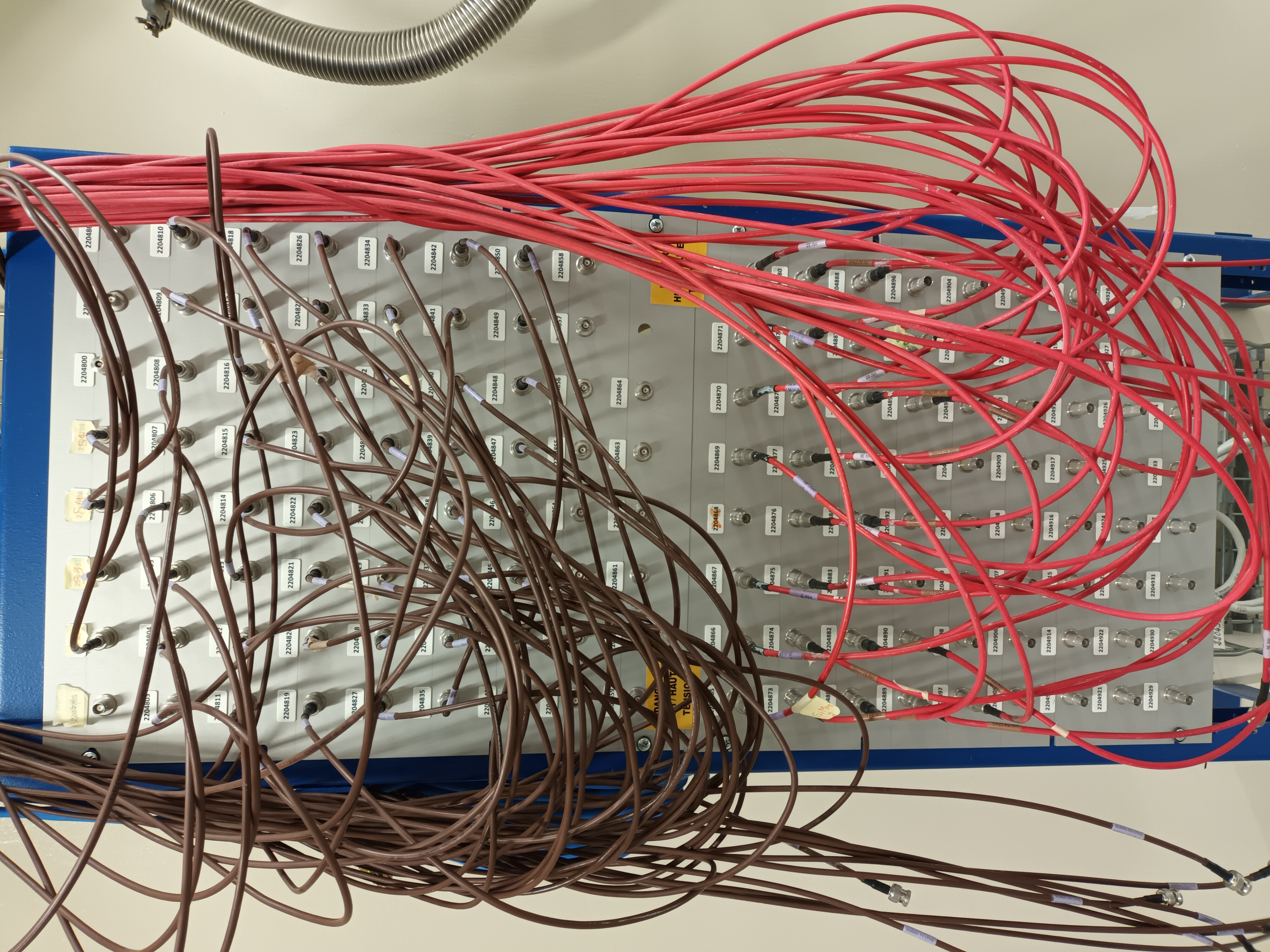
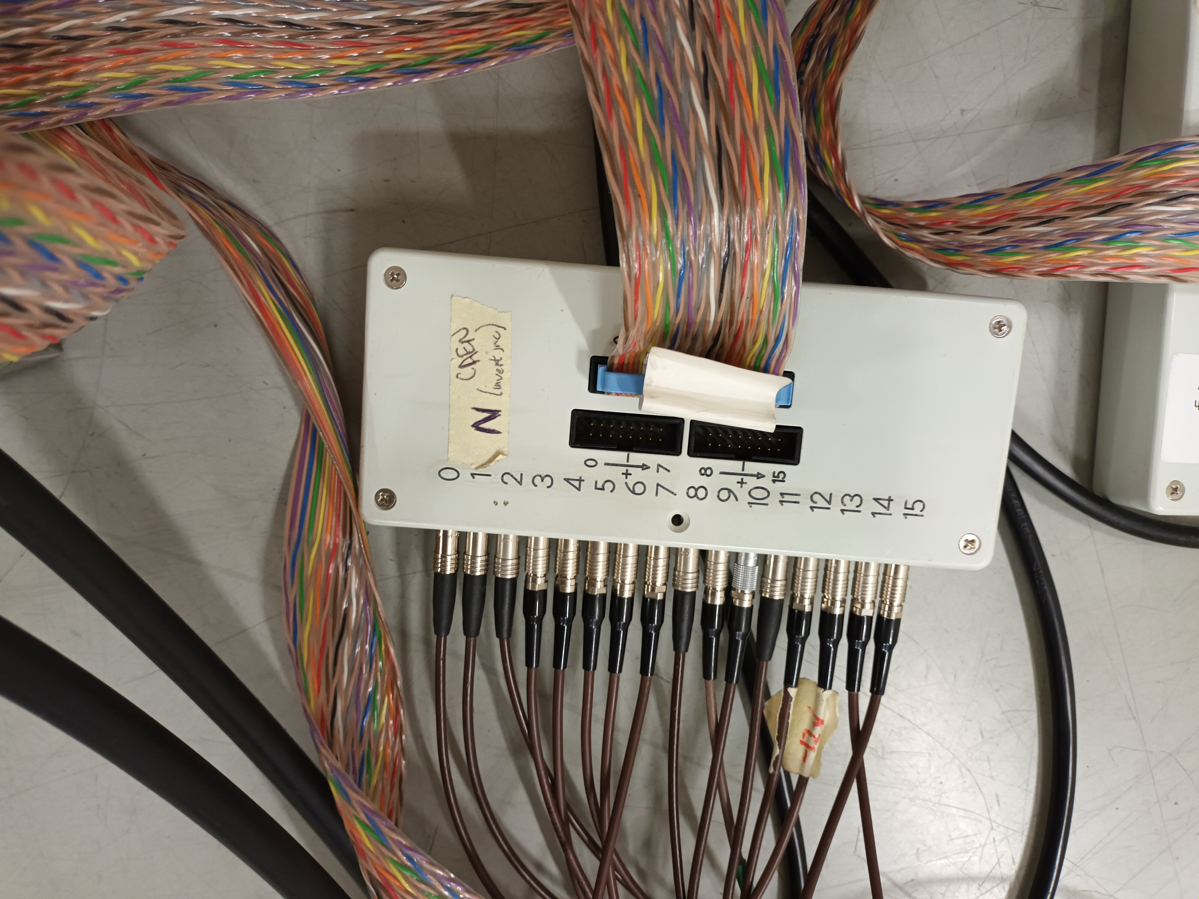
CLW | Detector Signal Cabling Al26 Aug 2023 |
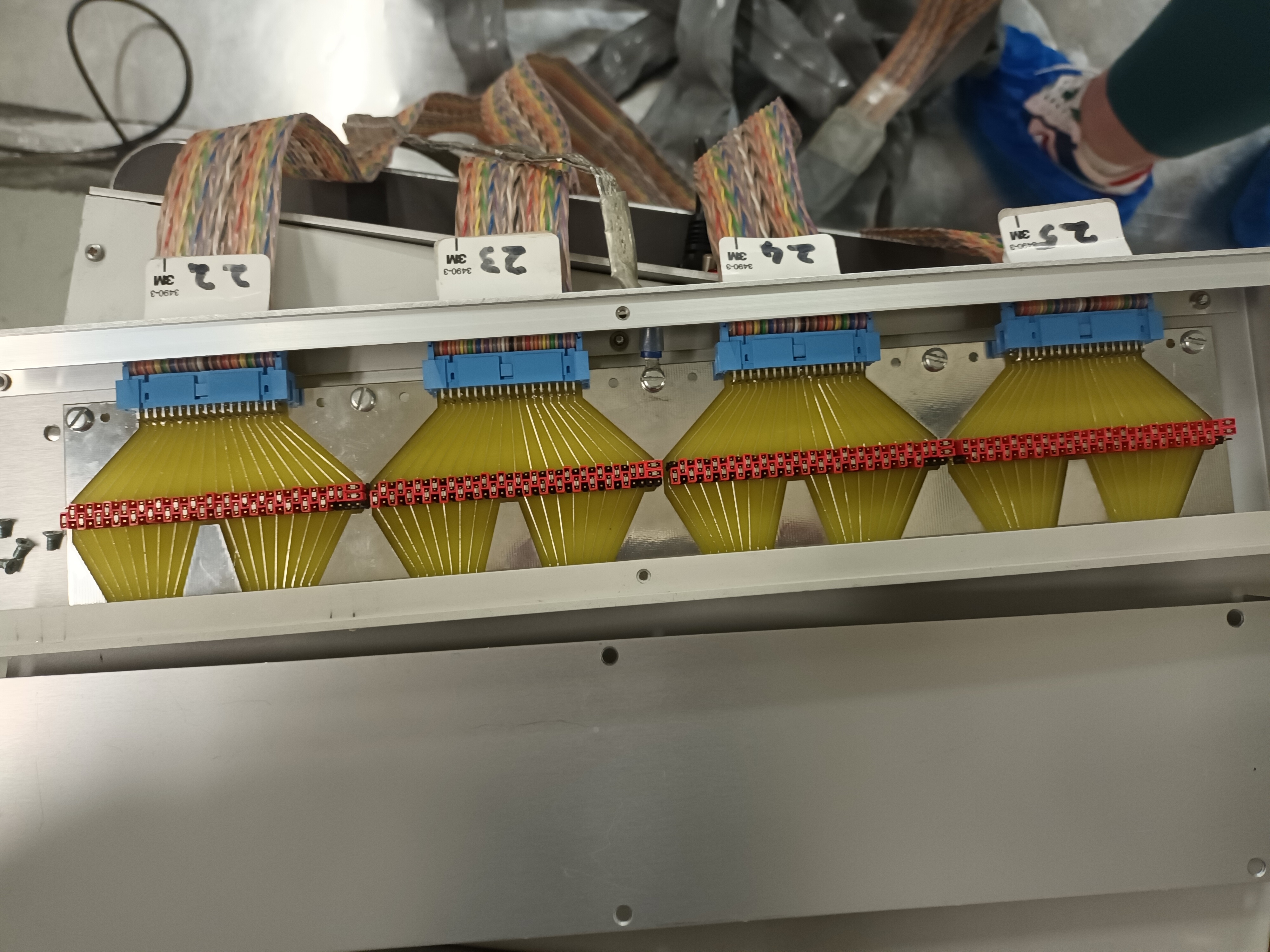
delta E detector Cabling
| Lemo Box Output Number |
Signal Cable Bunker |
Patch Panel Number |
Signal Cable Rack Area |
FADC Number |
DAQ Channel |
| 0 |
72 |
2204803 |
9 |
02911 |
DEED-1 |
| 1 |
73 |
2204804 |
10 |
02911 |
DEED-2 |
| 2 |
74 |
2204805 |
11 |
02911 |
DEED-3 |
| 3 |
75 |
2204806 |
12 |
02911 |
DEED-4 |
| 4 |
76 |
2204807 |
13 |
02914 |
DEED-5 |
| 5 |
77 |
2204808 |
14 |
02914 |
DEED-6 |
| 6 |
80 |
2204809 |
15 |
02914 |
DEED-7 |
| 7 |
81 |
2204810 |
16 |
02914 |
DEED-8 |
| 8 |
82 |
2204811 |
17 |
02917 |
DEED-9 |
| 9 |
85 |
2204812 |
18 |
02917 |
DEED-10 |
| 10 |
86 |
2204813 |
19 |
02917 |
DEED-11 |
| 11 |
87 |
2204814 |
20 |
02917 |
DEED-12 |
| 12 |
88 |
2204815 |
21 |
02916 |
DEED-13 |
| 13 |
90 |
2204816 |
22 |
02916 |
DEED-14 |
| 14 |
95 |
2204817 |
23 |
02916 |
DEED-15 |
| 15 |
96 |
2204818 |
24 |
02916 |
DEED-16 |
E p side cabling
| Lemo Box Output Number |
Signal Cable Bunker |
Patch Panel Number |
Signal Cable Rack Area |
FADC Number |
DAQ Channel |
| 0 |
97 |
2204819 |
25 |
4683 |
EDET-1 |
| 1 |
101 |
2204820 |
26 |
4683 |
EDET-2 |
| 2 |
103 |
2204821 |
27 |
4683 |
EDET-3 |
| 3 |
104 |
2204822 |
28 |
4683 |
EDET-4 |
| 4 |
105 |
2204823 |
29 |
4684 |
EDET-5 |
| 5 |
106 |
2204824 |
30 |
4684 |
EDET-6 |
| 6 |
107 |
2204825 |
31 |
4684 |
EDET-7 |
| 7 |
108 |
2204826 |
32 |
4684 |
EDET-8 |
| 8 |
109 |
2204827 |
33 |
4682 |
EDET-9 |
| 9 |
110 |
2204828 |
34 |
4677 |
EDET-10 |
| 10 |
111 |
2204829 |
35 |
4682 |
EDET-11 |
| 11 |
112 |
2204830 |
36 |
4682 |
EDET-12 |
| 12 |
113 |
2204831 |
37 |
4697 |
EDET-13 |
| 13 |
114 |
2204832 |
38 |
4697 |
EDET-14 |
| 14 |
116 |
2204833 |
39 |
4697 |
EDET-15 |
| 15 |
117 |
2204834 |
40 |
4697 |
EDET-16 |
E n side cabling
| Lemo Box Output Number |
Signal Cable Bunker |
Patch Panel Number |
Signal Cable Rack Area |
FADC Number |
DAQ Channel |
| 0 |
118 |
2204835 |
41 |
5348? |
EDET-17 |
| 1 |
119 |
2204836 |
42 |
5348? |
EDET-18 |
| 2 |
120 |
2204837 |
43 |
5348? |
EDET-19 |
| 3 |
121 |
2204838 |
44 |
5348? |
EDET-20 |
| 4 |
123 |
2204839 |
45 |
4677 |
EDET-21 |
| 5 |
124 |
2204840 |
46 |
4677 |
EDET-22 |
| 6 |
125 |
2204841 |
47 |
4677 |
EDET-23 |
| 7 |
126 |
2204842 |
48 |
2872 |
EDET-24 |
| 8 |
127 |
2204843 |
49 |
4636 |
EDET-25 |
| 9 |
128 |
2204844 |
50 |
4636 |
EDET-26 |
| 10 |
129 |
2204845 |
51 |
4636 |
EDET-27 |
| 11 |
130 |
2204846 |
52 |
4636 |
EDET-28 |
| 12 |
131 |
2204847 |
53 |
4674 |
EDET-29 |
| 13 |
132 |
2204848 |
54 |
4674 |
EDET-30 |
| 14 |
133 |
2204849 |
55 |
4674 |
EDET-31 |
| 15 |
134 |
2204850 |
56 |
4674 |
EDET-32 |
|
| Attachment 1: 20230809_120804.jpg
|
|
| Attachment 2: 20230809_121357.jpg
|

|
| Attachment 3: 20230809_153703.jpg
|
|
| Attachment 4: 20230809_153720.jpg
|
|
| Attachment 5: 20230809_153730.jpg
|

|
| Attachment 6: 20230809_153744.jpg
|

|
| Attachment 7: 20230809_192718.jpg
|

|
| Attachment 8: 20230810_090445.jpg
|

|
|
45
|
Thu Aug 10 09:10:02 2023 |
CLW | Detector Setup Al26 Run 2023 |
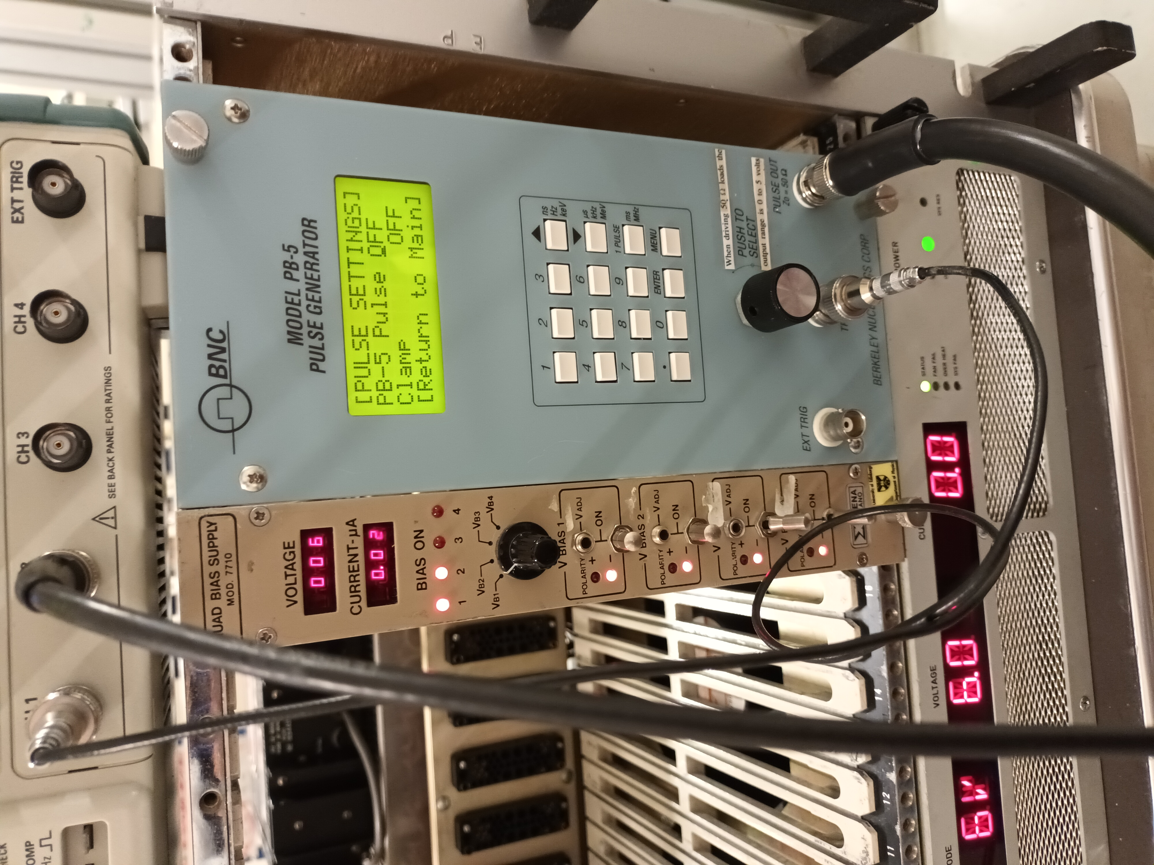
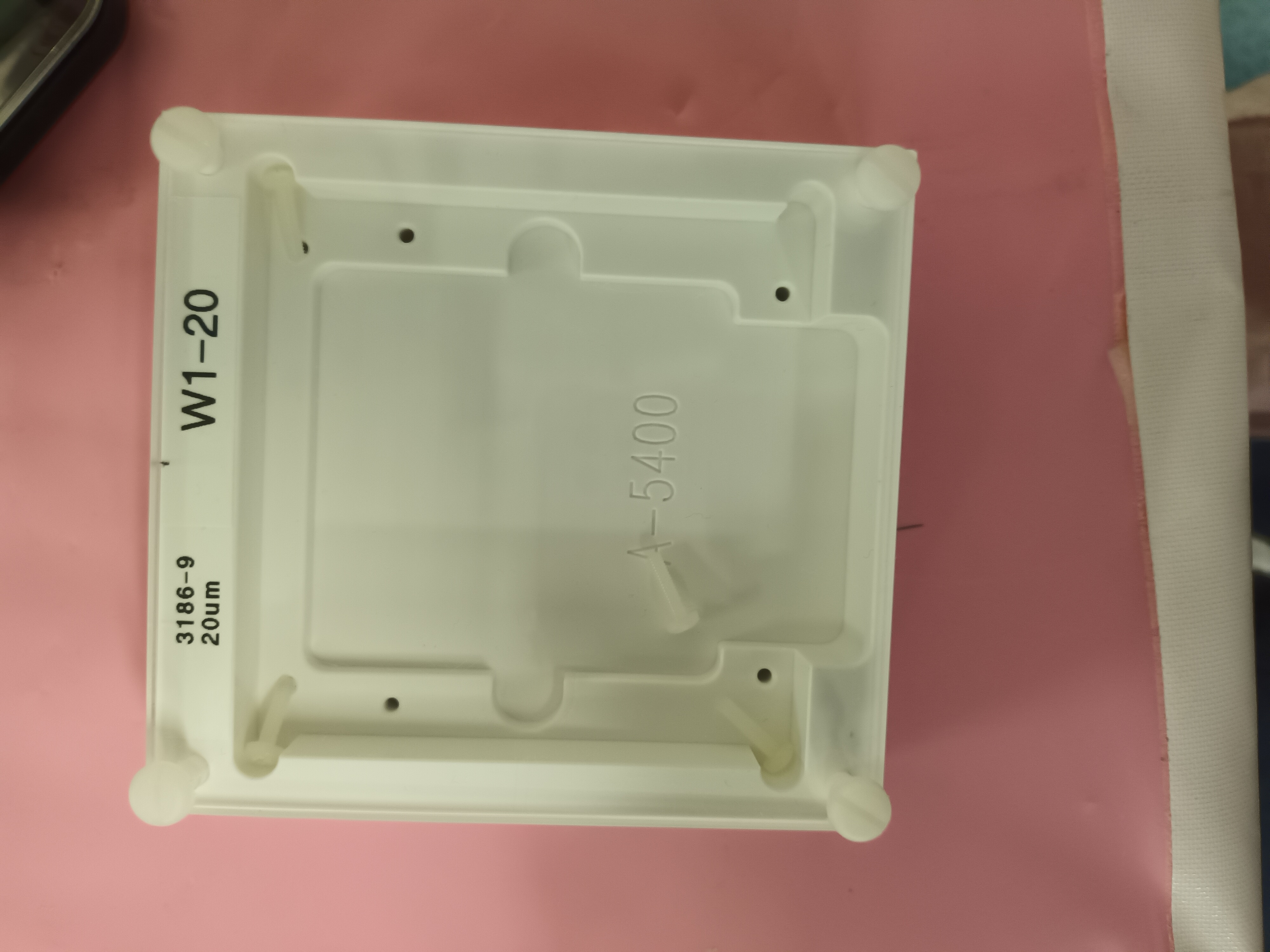
dE Detector: W1-20 3186-9 20 um
E Detector: W1-150 3458-4 144 um
Voltages and Leakage Currents:
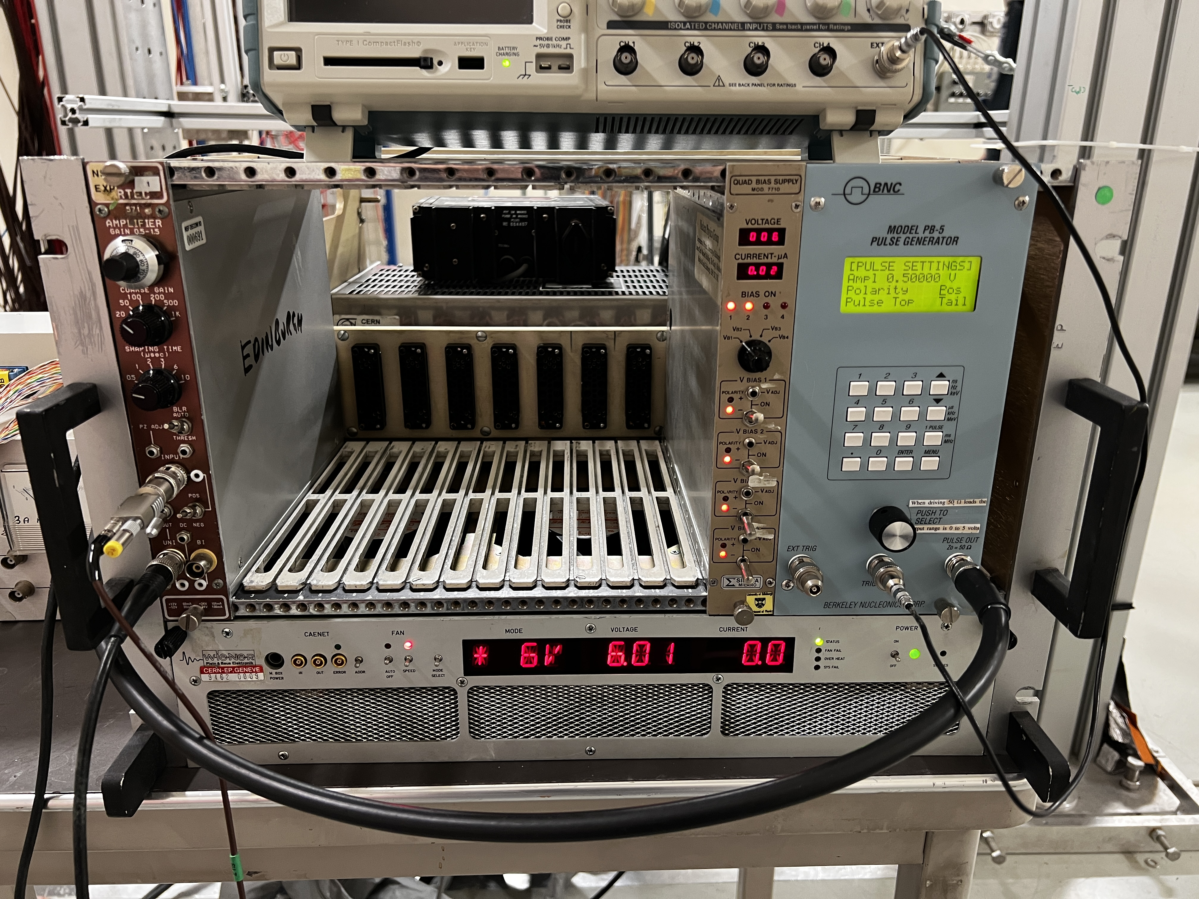
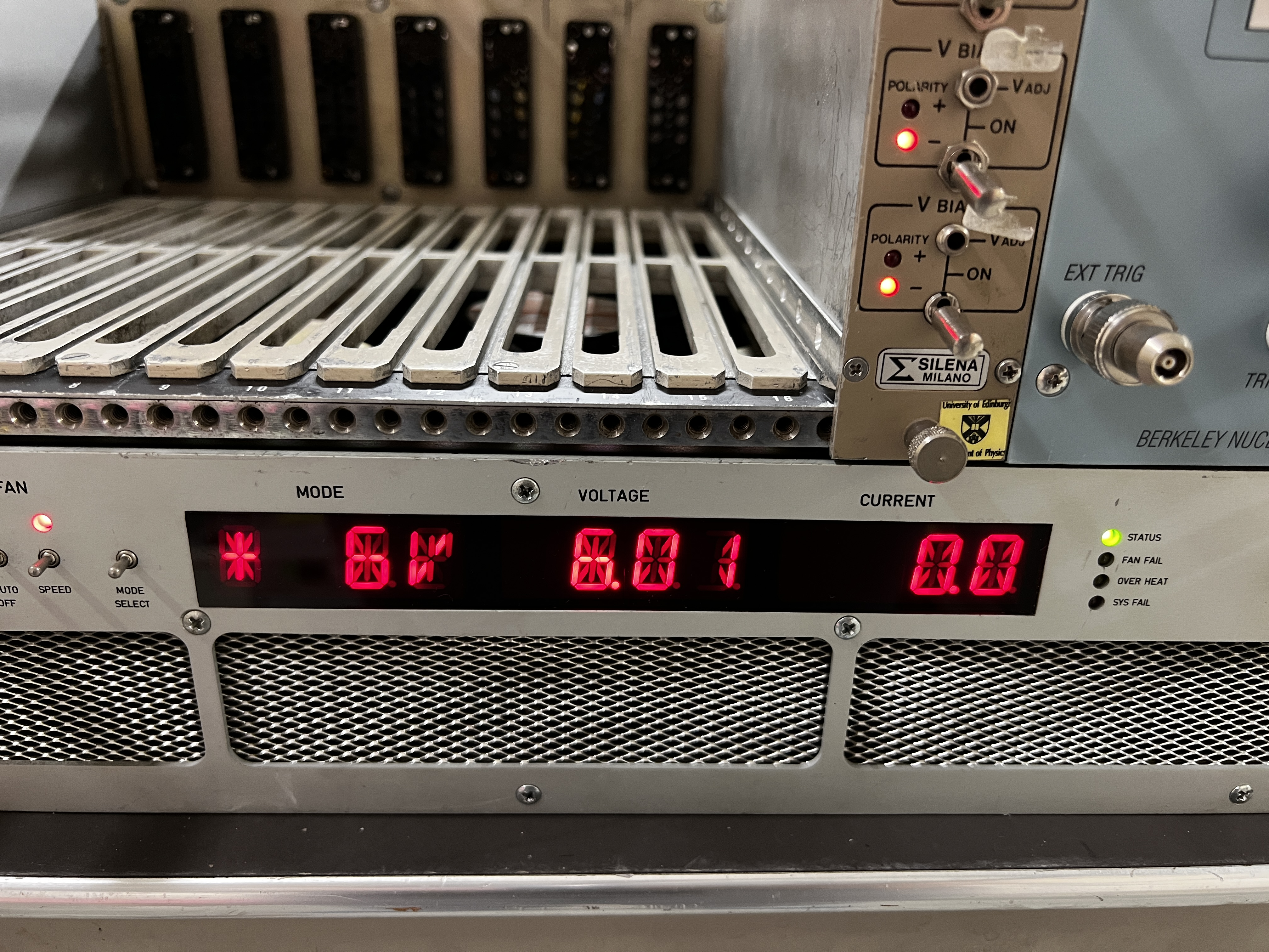
dE: 6 V, 0.02 muA
E: 50 V, 0.05 muA |
| Attachment 1: 20230809_181749.jpg
|
|
| Attachment 2: 20230809_181758.jpg
|

|
| Attachment 3: 20230809_172545.jpg
|

|
| Attachment 4: 20230809_172442.jpg
|
|
|
44
|
Mon Jul 31 10:21:41 2023 |
Nikolay Sosnin | n_TOF Data and Filtering |
|
| Attachment 1: Al26_Filtering.pptx
|
|
43
|
Thu Jul 27 11:53:52 2023 |
TD | MSL type W1 detector data for 26Al(n,X) experiment EAR2, n_TOF |
MSL type W1(SS)-20

3186-9  20um Depletion voltage 3V Operating voltage 6V
3585-12 20um Depletion voltage 2V Operating voltage 4V

MSL type W1(DS)-150

3458-1 157um Depletion voltage 22V Operating voltage 52V
3458-4 144um Depletion voltage 18V Operating voltage 48V |