| ID |
Date |
Author |
Subject |
|
25
|
Wed Jan 28 16:19:05 2015 |
Patrick Coleman-Smith | [How To] Loading new firmware into a FEE64 |
Log into the FEE64 module using telnet.
use root
enter => /usr/sbin/flash_unlock /dev/mtd2
enter => /usr/sbin/flashcp -v /MIDAS/Aida/< filename>.bin /dev/mtd2
then logout when done.
The flashcp program will erase the existing contents, then write the new file and finally verify the result.
Power cycle the FEE64 will load the new firmware.
The -v flag after the flashcp command ensures you can see what is going on.
There is a script in the /MIDAS/Aida directory called FlashPgm.csh which contains these commands and is used by the global re-programming command from the "Expert" menu on the RunControl page.
If you wish to program a lot of modules then alter the filename in the flashcp command in this script.
Please let me know if you see errors in this description.
|
|
26
|
Thu Jan 29 15:57:01 2015 |
Patrick Coleman-Smith | [How To] AIDA power supply alteration document |
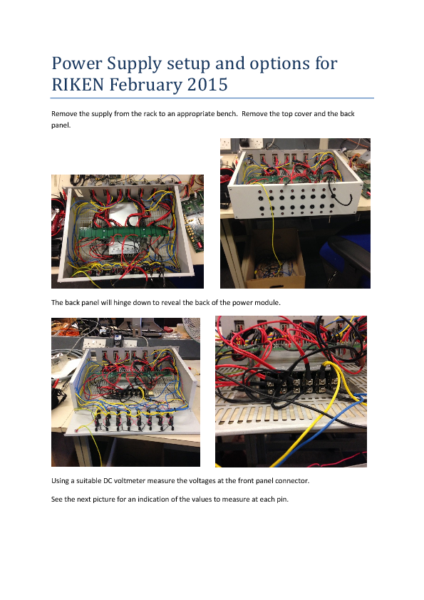
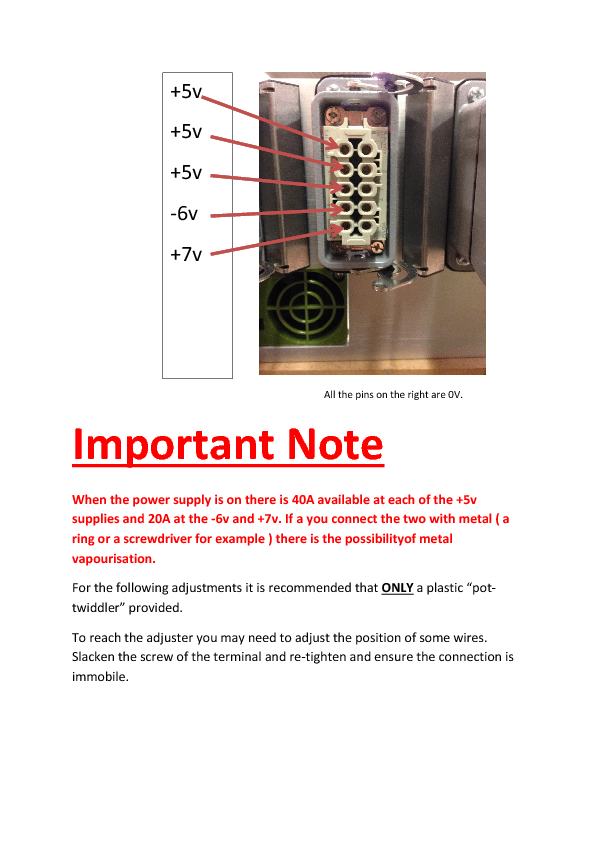
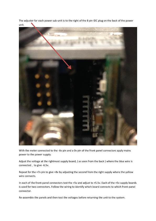
I've added the power supply change document.
Please have a look and let me know if it requires further clarification.
I have ordered some plastic "pot twiddlers".
I have run a simple test with the four FEE64 here + detector.
The sequence was :-
Run the system with filtered PSU and record FWHM for 1.4.L for each of the four FEE64 boards.
Replace the PSU with a standard but with outputs set as per the attachement.
Results were approx 1.5 x worse.
Replace filtered PSU..... back as expected.
Addition: For Filter PSU only :- Set +5v to +6v when the FEE64 is not attached.
This is required as the extar impedance of the filter drops the voltage too much by the time it reaches the FEE64. |
| Attachment 1: Power_Supply_setup_and_options_for_RIKEN_February_2015.pdf
|
|
|
29
|
Mon Feb 9 11:52:52 2015 |
Patrick Coleman-Smith | [ How To ] Integrating AIDA with other systems |
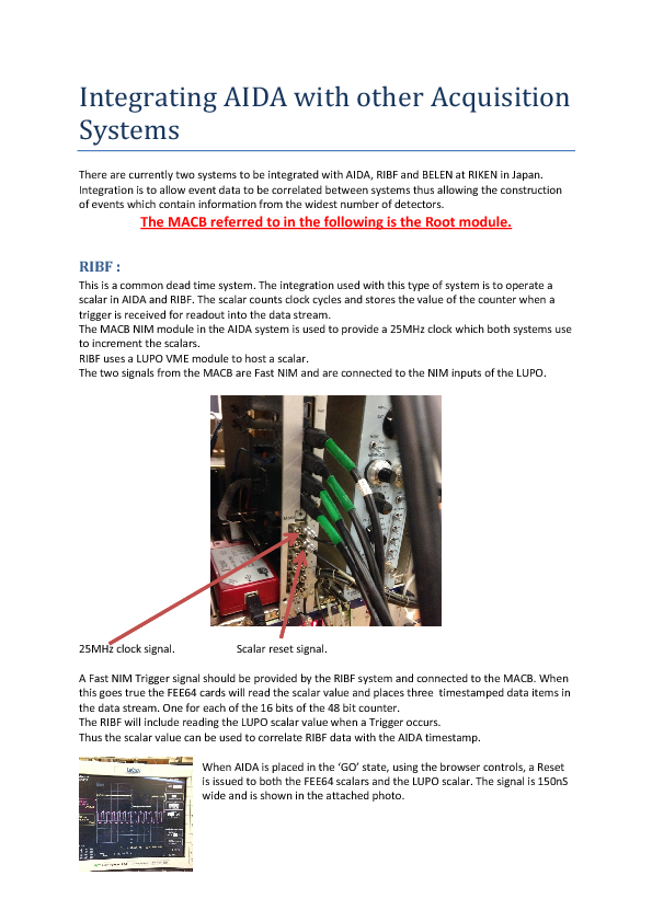
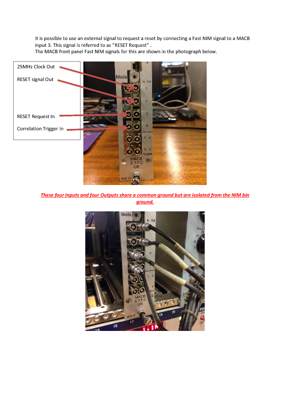
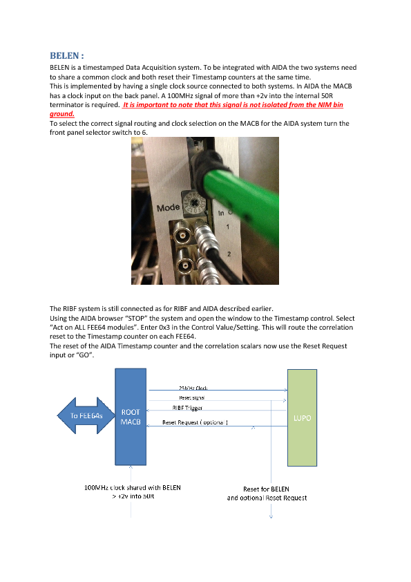
This document details how to integrate AIDA with other systems. |
| Attachment 1: Integrating_AIDA_with_other_Acquisition_Systems.pdf
|
|
|
34
|
Mon Feb 16 09:41:45 2015 |
Patrick Coleman-Smith | [How To] Set up the Raspberry Pi for PuTTY |
When logged in and before opening PuTTY open a cmdtool window.
cd /dev
sudo chmod 777 /dev/ttyUSB0
then you should be able to run PuTTY.
This is based on notes in my log-book.
|
|
35
|
Mon Feb 16 12:17:21 2015 |
Patrick Coleman-Smith | MACB update for 50Mhz external clock |
This version of the MACB has an additional selection at 5 for a ROOT module.
This will operate the Correlation Scalar signals used for RIBF and use the External Clock signal directly for the FEE64 50MHz distribution.
This has been tested at Daresbury with and external clock source and operates successfully with the merger.
|
| Attachment 1: macb_top_revB_16Feb15.jed
|
|
37
|
Tue Feb 17 08:03:32 2015 |
Patrick Coleman-Smith | [How To] Set up the Raspberry Pi for PuTTY |
| Quote: |
|
When logged in and before opening PuTTY open a cmdtool window.
cd /dev
sudo chmod 777 /dev/ttyUSB0
then you should be able to run PuTTY.
This is based on notes in my log-book.
|
Tried this when we got in this morning and successfully changed the permissions for /dev/ttyUSB0, but made no difference to the error received when opening the PuTTY session, which was:
PuTTy Fatal Error
Unable to open connection to:
Unable to open serial port. |
|
39
|
Wed Feb 18 11:25:54 2015 |
Patrick Coleman-Smith | Investigations into removing HV noise |
With the system in T9 and a Keithley Source Meter supplying HV to the detector.
The source meter supplies 200V and measures the current ....
I noticed that the current value was not stable... varying by +/-0.5uA. In conversation with Marcello i learnt that normally much more stable than this.
I have carried out the following changes.
added a 22nF X7R capacitor at the detector end of the Kapton cable from the HV connector pin ( G/R ) to the ground plane of the Kapton.
added a 14k resistor in series with the HV supply +ve signal before it connects to the adaptor board.
isolated the G/R connection on the second Kapton that would normally be connected to the HV on the detector.
The HV now is a lot quieter +/-0.01uA.
Next i disconnected the HV -ve input from ground at the adaptor board. This resulted in all the FEE64 being equally noisy!!
Next I connected a 22nF X7R capacitor between the HV negative and ground at the adaptor. This resulted in all FEE64 becoming equally calm.
The FWHM of the spectra is not good at 250 to 300 but the fact that all FEE64 are equal now is interesting.
I will update this post with pictures.
Update:-
This change was not stable and repeatable. I changed back to the original connections and things haven't gone back.
So power down and leave for today.... It doesn't make sense to me ... but then that's nothing new :-)
It appears that something is heating/charging up during the day and the noise becomes swamped by this effect ???? |
|
52
|
Mon Mar 9 09:02:03 2015 |
Patrick Coleman-Smith | Adding Filters to the AIDA PSU. |
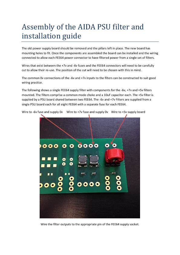
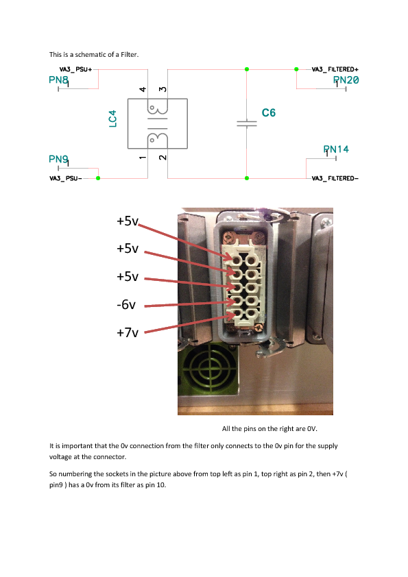
This guide is to help with the filter pcb assembly and installation into the AIDA power supply. |
| Attachment 1: Assembly_of_the_AIDA_PSU_filter_and_installation_guide.pdf
|
|
|
79
|
Wed Apr 29 10:01:27 2015 |
Patrick Coleman-Smith | Fast Trigger output fault in FEE64 FPGA logic |
The Fast Trigger output of the FEE64 is formed from the OR of the four OR16 signals ( one from each of the ASICs.
The logic levels of the OR16 signals are active low in the FPGA and so if the are OR'd together then the output is inactive if any one of the ASICs is inactive.
This is a problem when the Fast Trigger is being used by other DAQ systems.
A new FPGA program 0x1b4FE01A ( version 26 ) is being compiled.
The Fast Trigger output will provide the logic AND of the four OR16 signals which should give the correct signal. This setting is selected by "Setup".
The other settings available using the Trigger register are shown below. Note that OR64 is the logic OR of the masked outputs of the ASIC individual Discriminator outputs.
when 0 =>
trigger_hit <= ASIC1_data_ready ;
when 1 =>
trigger_hit <= ASIC1_rdo_range and ASIC1_data_ready ;
when 2 =>
trigger_hit <= ASIC2_rdo_range and ASIC2_data_ready ;
when 3 =>
trigger_hit <= led_trigger(0) ;
when 4 =>
trigger_hit <= led_raw(0) ;
when 5 =>
trigger_hit <= chan_reset(0) ;
when 6 =>
trigger_hit <= force_capture_sync ;
when 7 =>
trigger_hit <= force_capture ;
when 8 =>
trigger_hit <= ASIC1_OR_16 ;
when 9 =>
trigger_hit <= ASIC2_OR_16 ;
when 10 =>
trigger_hit <= ASIC3_OR_16 ;
when 11 =>
trigger_hit <= ASIC4_OR_16 ;
when 12 =>
trigger_hit <= ASIC4_OR_16 and ASIC3_OR_16 and ASIC2_OR_16 and ASIC1_OR_16;
when 13 =>
trigger_hit <= led_trigger(1) ;
when 14 =>
trigger_hit <= OR64 ;
when 15 =>
trigger_hit <= ASIC4_OR_16 or ASIC3_OR_16 or ASIC2_OR_16 or ASIC1_OR_16; |
|
81
|
Wed Apr 29 11:34:09 2015 |
Patrick Coleman-Smith | Fast Trigger timings against Pulser Input and LEC/MEC Fast Comparator threshold setting |
I have tried the latest version ( 26 ) of the FEE64 code and carried out some measurements of the Fast Trigger delay from the Pulser signal ( not the Pulser Trigger out ) and observed the following.
The pulser gives a centroid of 28217 in the histogram.
| Threshold setting |
Delay observed at MACB Fast Trigger output (nS) |
| 0x40 |
no Trigger |
| 0x38 |
no Trigger |
| 0x30 |
no Trigger |
| 0x28 |
1200 to 1800 |
| 0x20 |
690 to 860 |
| 0x18 |
505 to 600 |
| 0x10 |
320 to 385 |
| 0x8 |
210 to 270 |
This seems to me to be sensible as the discriminator is only a very simple comparator.
The OR64 ( 0xE ) signal works as True Fast NIM Logic. The OR16s ( 0xC ) logic works as inverse Fast NIM.
The OR64 is derived from the individual masked discriminator outputs. By default the Mask is not set.
|
|
86
|
Thu Apr 30 15:28:25 2015 |
Patrick Coleman-Smith | High Energy Spectra from LYCCA with pulser |
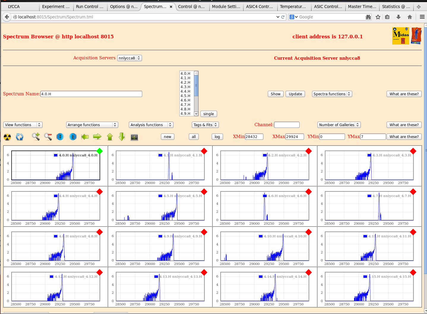
I have an eight FEE64 system now in place on the LYCCA chamber with a PB-5 pulser going into the adapter cards test input. The test capacitor is 30pF.
I was going to explore the effect of the thresholds on the pulser peak.
I notice that the spectra look like those taken in RIKEN and not a single peak. In the 1GeV range I would interpret this as noise but since this is such a high energy i don't quite understand what is happening in the ASIC.
I thought i would share it with you.
PB-5 input to 50R is 10v with no attenuation. Signal height on the inline 'scope is +5.2v
ASICs are set to "default" with 1GeV range and 3uS shaping time.
Let me know if anything useful can be gleaned by more tests on LYCCA. |
| Attachment 1: LYCCA_High_Energy.png
|
|
|
88
|
Thu Apr 30 17:43:36 2015 |
Patrick Coleman-Smith | High Energy Spectra from LYCCA with pulser |
I have an eight FEE64 system now in place on the LYCCA chamber with a PB-5 pulser going into the adapter cards
test input. The test capacitor is 30pF.

I was going to explore the effect of the thresholds on the pulser peak.

I notice that the spectra look like those taken in RIKEN and not a single peak. In the 1GeV range I would
interpret this as noise but since this is such a high energy i don't quite understand what is happening in the
ASIC.

I thought i would share it with you.

PB-5 input to 50R is 10v with no attenuation. Signal height on the inline 'scope is +5.2v

ASICs are set to "default" with 1GeV range and 3uS shaping time.

Let me know if anything useful can be gleaned by more tests on LYCCA.


Q = CV = 30pF * 5V = 150pC => ~ 3.42GeV => ADC channel ~ 27880

The spectra imply a positive test input. The spectra imply an inconsistency between the data
supplied and the peak position.

You display the spectra on a log scale ...  so the majority of events are in the peak ... but
why do some channels so a peak and others a peak plus a small number of higher amplitude/events?

What ASIC settings are you using?

What is the PB-5 frequency? ... PB-5 settings? |
|
89
|
Thu Apr 30 20:21:20 2015 |
Patrick Coleman-Smith | High Energy Spectra from LYCCA with pulser |
> I have an eight FEE64 system now in place on the LYCCA chamber with a PB-5 pulser going into the adapter cards
> test input. The test capacitor is 30pF.
>
> I was going to explore the effect of the thresholds on the pulser peak.
>
> I notice that the spectra look like those taken in RIKEN and not a single peak. In the 1GeV range I would
> interpret this as noise but since this is such a high energy i don't quite understand what is happening in the
> ASIC.
>
> I thought i would share it with you.
>
> PB-5 input to 50R is 10v with no attenuation. Signal height on the inline 'scope is +5.2v
>
> ASICs are set to "default" with 1GeV range and 3uS shaping time.
>
> Let me know if anything useful can be gleaned by more tests on LYCCA.
>
>
>
> Q = CV = 30pF * 5V = 150pC => ~ 3.42GeV => ADC channel ~ 27880
>
> The spectra imply a positive test input. The spectra imply an inconsistency between the data
> supplied and the peak position.
>
> You display the spectra on a log scale ...  so the majority of events are in the peak ... but
> why do some channels so a peak and others a peak plus a small number of higher amplitude/events?
>
> What ASIC settings are you using?
>
> What is the PB-5 frequency? ... PB-5 settings?

PB-5 is at 100Hz, fall time is 1 ms.
ASIC settings default from VHDL.
They are in the manual. See EDOC955 at npg.dl.ac.uk

29300 => 2.1GeV ( very approx )  so yes this doesn't make sense.
Hard to have a specific calibration or will your beam time give that.

I think the 30pF is correct but i can measure it on Wednesday...... |
|
111
|
Wed Jul 1 16:42:39 2015 |
Patrick Coleman-Smith | Testing Version 8 |
I have installed Version 8 of the AidaExec program and FEE_GF_Feb15_6.bin for the VHDL on the system in T9.
On the whole the new firmware operates successfully.
I am now pursuing a few niggles.
I have disconnected the detector in order to have a deterministic set of data through the system.
If the system is required for other tests please let me know and the V7 setup can be restored quite quickly.
|
|
113
|
Thu Jul 16 15:10:34 2015 |
Patrick Coleman-Smith | [DAQ and VHDL] Changes to the Discriminator Information data item |
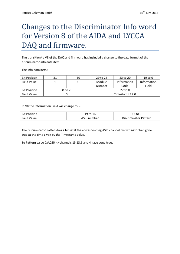
I have attached a document describing the new format of the Discriminator Information data item used in Version 8 |
| Attachment 1: Changes_to_the_Discriminator_Info_word_for_Version_8_of_the_AIDA_and_LYCCA_DAQ_and_firmware.pdf
|
|
|
225
|
Fri May 13 13:24:42 2016 |
Patrick Coleman-Smith | An idea that might help when everything grinds to a halt |
When using the T9 system and running with too much rate in one FEE64 so the system is unbalanced.
I found a good way to understand this and to be able to operate the controls of the FEE64s was to place the Merger in "Pause" mode.
Then the data is extracted from the busy FEE64 but it can still be controlled.
When there is unbalance in the system it is possible for one or more queue in the Merger to become full and so the communication with that FEE64 is not possible.
Placing the Merger in Pause mode will mean all the data is discarded, the links run at full speed and action can be taken on the problem FEE64(s) to help balance the system out better.
I hope this helps .... it is highly likely that this is already being done.....
Perhaps a wise sequence when starting the whole DAQ is to operate with the Merger in Pause mode and only switch it to merging when the user is happy with the rates.
In the statistics window of the FEE64 there is an indication of the data being transferred over the link.
When deciding how to run the experiment thought needs to be given to the various maximum rates. The rate from the FEE64 is 500k events/sec. If running with 26 FEE64 then this goes up to 13M events/sec. An event is 64 bits.
I'm not sure what the maximum rates are in the Merger and the TapeServer.
|
|
229
|
Mon May 23 09:17:55 2016 |
Patrick Coleman-Smith | Multiplicity Trigger Specification |
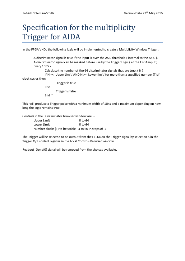
Please read and comment on the attached specification. |
| Attachment 1: Specification_for_the_multiplicity_Trigger_for_AIDA.pdf
|
|
|
230
|
Mon May 23 17:21:29 2016 |
Patrick Coleman-Smith | [HowTo] A solution to the problem of no SYNCs |
When starting Aida some FEE64 fail to provide SYNC data , or any data for that matter, on the ASIC data stream.
The problem is that the ASIC Readout is not starting properly and is becoming stuck waiting for an internal
event which will never arrive.
The chief source has been found to be the Correlation part of the VHDL. The reason is not yet clear but the work
around of disabling the Correlation part of all of the FEE64 at 'GO' except the Master has allowed the System to
start with all FEE64 producing SYNCs.

This change is now incorporated in the sys.tcl file which is used when 'GO' is activated in the RunControl window.

The Master is required as it provides the 25Mhz clock and the Reset pulse. The Correlation Trigger will cause a
correlation data item to be put in the Master ASIC data stream.
Only one Correlation data item is required in the data stream, so having just the Master should be fine.

If it is required to enable another FEE64 then do this after 'GO' by opening the Correlation Browser window from
the Control window and set the Control ( at offset 0 ) to 0x0001.

Should one of the FEE64s still fail to provide SYNCs first try to 'STOP' , 'GO' the system two times and see
if that works.

A further means of correcting the problem is to directly reset the ASIC Readout using the Data Readout Window
available through the Control window. In the ASIC Readout - buffer status & control (0x300) section enter 0x4000
into the Control register to reset the state machines. Then enter 0x0001 to re-enable them. This may solve the
problem.

This is all by no means an ideal situation and the source will be found and the problem solved. |
|
234
|
Tue May 24 08:28:28 2016 |
Patrick Coleman-Smith | [HowTo] Save power if not using the Waveforms and restart the Waveforms |
The USB controlled power Relays are near their AC fuse operating limit which has caused some Fuse failures.
To reduce the power consumption of each FEE64 it is possible to power down the Waveforms ADCs saving about 20W per FEE64.

To Powerdown the ADCs in a FEE64 use the 'Local Data' browser window from the 'Control' browser window. Change the setting of the ADC Control
Register at offset 2 from 0 to 0xFF. All the FEE64s can be thus controlled by using the 'Act on all' tick box.
Clearly, the System Check for ADC calibration will now fail for all those that are powered down.

To Power up the ADCs change the setting from 0xFF to 0. Then using the FADC Calibration browser window calibrate the FADCs.

The SYSTEM should be in the 'STOP' state during these procedures.

Should the SYSTEM be power cycled then the ADCs will be powered up.

Saving at the 16A AC fuse is estimated to be 3A as there are 16 FEE64 being powered through each. |
|
236
|
Wed May 25 18:51:54 2016 |
Patrick Coleman-Smith | [HowTo] Use the Multiplicity Trigger Firmware, V8.18, and update the files |
The attached firmware file, FEE_GF_Feb16_18.bin, should be saved to /MIDAS/Aida and the FlashPgm.csh file edited
to load "FEE_GF_Feb16_18.bin"

Use the Run Control Expert command to update the firmware on all the FEE64s.

Power cycle the FEE64s to load the new firmware.

Make a backup copy of the files in the directory /MIDAS/TclHttpd/Html/AIDA/DISC.

Unzip the files from DISC_25May16.zip and copy them into /MIDAS/TclHttpd/Html/AIDA/DISC to replace the existing
ones.

Make a backup copy of the file /MIDAS/TclHttpd/Html/AIDA/LOCAL.tml

Unzip the file from LOCAL_tml_25May16.zip and copy into /MIDAS/TclHttpd/Html/AIDA/LOCAL to replace the existing
file.

'RESET' and browser refresh the two updated control windows to load the new software.
-----------------------------------------------------

To use the Multiplicity Trigger:-
In the Local Controls select option 5 for the Trigger.

In the Discriminator window.

Set the 'Upper Limit'
Set the 'Lower Limit' ( always greater than 0 ..... or the Trigger will always be present )
Set the 'Time window'. The number of 10nS clocks. So 4 => 40nS. Register is 0 to 255.

-----------------------------------------------------

These registers are not in the Save/Restore set yet.

Tested on the T9 system using the pulser and setting/clearing Mask bits.

Please let me know how this works for you. |
| Attachment 1: FEE_GF_Feb16_18.bin
|
| Attachment 2: DISC_25May16.zip
|
| Attachment 3: LOCAL_tml_25May16.zip
|