ID |
Date |
Author |
Subject |
|
41
|
Fri Feb 20 10:04:29 2015 |
CG, AE, TD | Fri 20th progress |
20/02/15
1400: Measured leakage current as function of bias V for the Caen 1419B high voltage supply and detector BB18 2977-20. (see attachment #1)
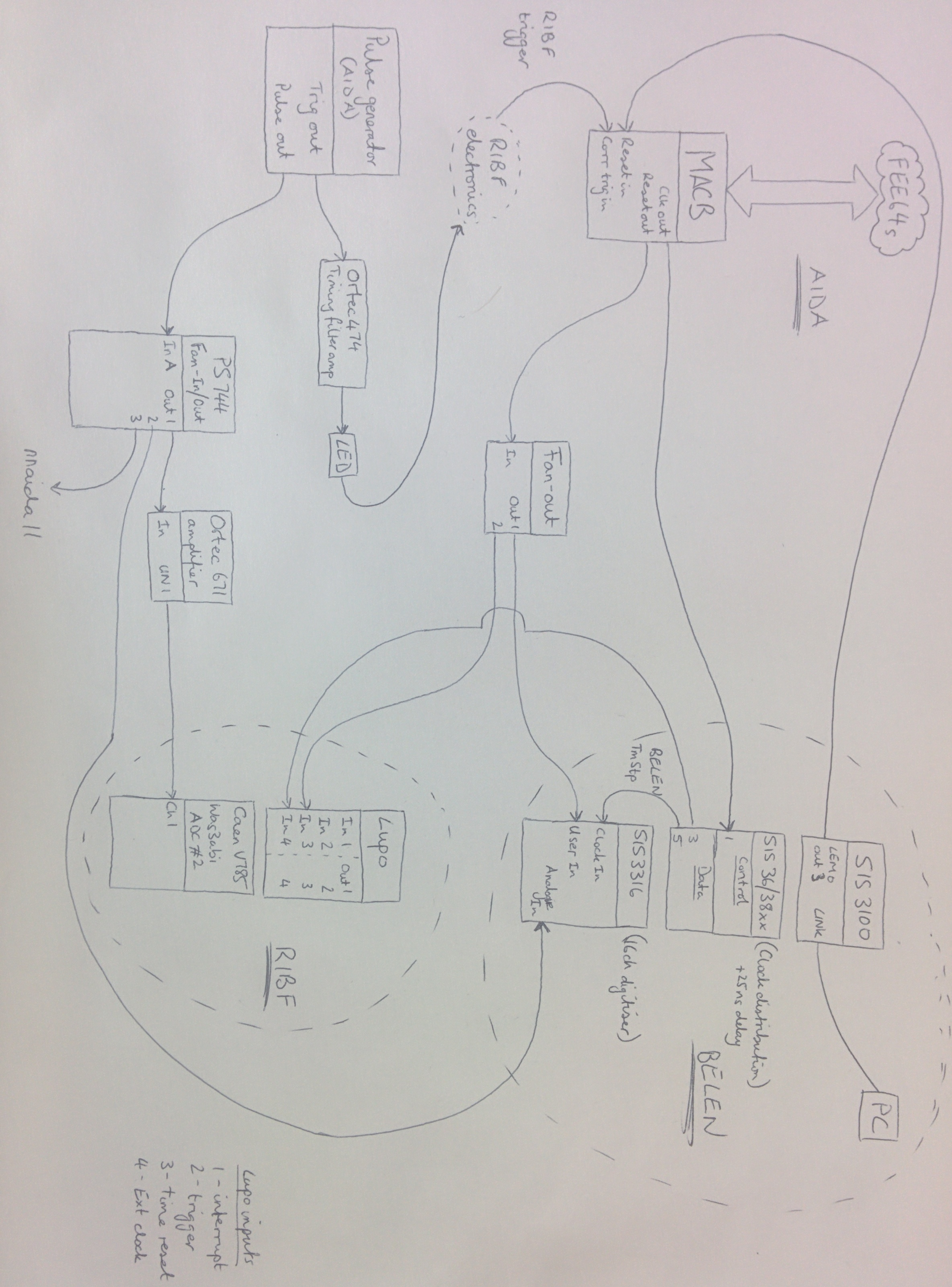
1500: Modified MACB installed and connected to BELEN and RIBF DAQs (see attachment #2 for signal flow diagram).
Increased noise in several nnaida, possibly due to grounding issues introduced by inclusion of modules for other DAQs. |
| Attachment 1: bias_voltage_vs_leakage_current_for_caen_n1419b_and_detector_bb18_2977-20(2).png
|
.png.png)
|
| Attachment 2: 2015-02-20_20.27.57.jpg
|
|
|
42
|
Fri Feb 20 10:48:09 2015 |
TD | How To Connect the FEE64 System Console Using PuTTY |
Set permissions for the USB-serial device using the command

sudo chmod 777 /dev/ttyUSB0

Note: Vic Pucknell reports that he has sometime observed the device
rotate between /dev/ttyUSB0, /dev/ttyUSB1, /dev/ttyUSB2 etc - make\
sure you are using the correct device name with the command:

ls -l /dev/ttyUSB*


Start PuTTY

Select Connection Type 'Serial'
Enter Serial Line (/dev/ttyUSB0 or /dev/ttyUSB1)
Enter speed (9600)
Select 'Open'

Note: permissions for the USB-serial device will revert to their
default (mode 440) when the OS notices the change but by then
the serial line connection will have been established. |
|
43
|
Sat Feb 21 06:37:52 2015 |
CG, AE, TD | Sat 21st Feb progress |
21/02/15
1230: Developing the software to check synchronisation between DAQs. Below line runs program on aidas1 - sends data from TapeServer to BELEN.
./DataRelayFilter -n 10.32.6.196 -p 10307 -I 2
1500: Investigating pulser peak FWHMs as function of bias voltage.
Constant shaping time of 0x3, slow comp thresh 0x20, fast comp thresholds of 0xff. All other setting as standard. Detector MSL BB18 2977-20.
Results summarised in table directly below.
| |
Pulser peak FWHM (ch) |
| |
|
nnaida1 |
nnaida3 |
nnaida6 |
nnaida8 |
| Bias (v) |
Leakage current (uA) |
1.9.L |
2.10.L |
1.9.L |
2.9.L |
2.10.L |
3.11.L |
2.10.L |
3.9.L |
| 75 |
10.700 |
166 |
133 |
174 |
156 |
176 |
168 |
271 |
285 |
| 100 |
10.905 |
165 |
131 |
174 |
158 |
168 |
166 |
272 |
285 |
| 125 |
11.090 |
167 |
151 |
175 |
158 |
167 |
160 |
271 |
285 |
| 150 |
11.410 |
179 |
140 |
178 |
158 |
169 |
166 |
271 |
283 |
| 200 |
12.275 |
----- |
------ |
175 |
159 |
------ |
------ |
272 |
286
|
At bias of -200V nnaida1+6 stopped outputting data but continued to produce SYNCs. Good event rate dropped from ~few thousand per sec to ~300 per sec.
After returning bias to -150V, nnaida1+6 started producing data again. No effect was seen in nnaida3+8.
nnaida8 peaks are not particularly Gaussian in shape. Look more skewed with one rolling edge and one side a relatively sharp drop.
No obvious trends with changing bias voltage. Will return to -100V.
1545: Investigating pulser peak FWHMs as function of shaping time.
Bias returned to -100V, with leakage current 11.000uA.
Settings for all nnaida: slow comp thresh = 0x20, fast comp thresh = 0xff, hold time = 0x4 if shaping time <= 0x8, 0x8 if shaping time > 0x8.
| Pulser peak FWHM (ch) |
| |
nnaida1 |
nnaida3 |
nnaida6 |
nnaida8 |
| Shaping time (Hex) |
1.9.L |
2.10.L |
1.9.L |
2.9.L |
2.10.L |
3.11.L |
2.10.L |
3.9.L |
| 0x0 |
254 |
172 |
151 |
160 |
172 |
164 |
287 |
293 |
| 0x1 |
237 |
167 |
176 |
172 |
184 |
176 |
328 |
367 |
| 0x2 |
193 |
146 |
184 |
168 |
180 |
175 |
306 |
321 |
| 0x4 |
149 |
119 |
171 |
152 |
159 |
155 |
252 |
261 |
| 0x8 |
129 |
122 |
154 |
147 |
139 |
137 |
195 |
201 |
| 0xb |
133 |
129 |
160 |
148 |
137 |
135 |
184 |
188 |
| 0xf |
139 |
139 |
169 |
159 |
141 |
142 |
184 |
183 |
Visual 'analysis' suggested 0xb to be the optimal value so used that as shaping time in further tests.
(Graph to follow)
1900: Investigating effect of changes to slow comparator thresholds.
Settings: bias = -100V, hold timing = 0x8, shaping time = 0xb, fast comp thresholds = 0xff. Otherwise, standard settings.
| Position of threshold (ch) |
| |
nnaida1 |
nnaida3 |
nnaida6 |
nnaida8 |
| Slow comp threshold |
1.9.L |
2.10.L |
1.9.L |
2.9.L |
2.10.L |
3.11.L |
2.10.L |
3.9.L |
| 0x20 |
32164 |
32378 |
33102 |
32990 |
32427 |
32261 |
33433 |
33433 |
| 0x18 |
32271 |
32481 |
32997 |
32890 |
32529 |
32369 |
33334 |
33349 |
| 0x10 |
32389 |
32589 |
32898 |
32788 |
32648 |
32449 |
33225 |
33260 |
| 0xd |
32420 |
32596 |
32858 |
32755 |
------ ? |
----- ? |
----- ? |
----- ? |
With threshold at 0xd, threshold position was very hard to determine for nnaida6+8, assume discirminator is running in the noise. Will ignore data for 0xd.
Assuming central position of 32768 and energy per channel of 0.7 keV, below table gives approximate position of threshold in keV.
| Position of threshold (ch) |
| |
nnaida1 |
nnaida3 |
nnaida6 |
nnaida8 |
| Slow comp threshold |
1.9.L |
2.10.L |
1.9.L |
2.9.L |
2.10.L |
3.11.L |
2.10.L |
3.9.L |
| 0x20 |
423 |
273 |
234 |
155 |
239 |
355 |
467 |
467 |
| 0x18 |
348 |
201 |
160 |
85 |
167 |
279 |
396 |
407 |
| 0x10 |
265 |
125 |
91 |
14 |
84 |
223 |
320 |
344 |
Thus (very roughly), between 0x10 and 0x20, the above table shows the threshold moving by about 10 keV per increment in the threshold.
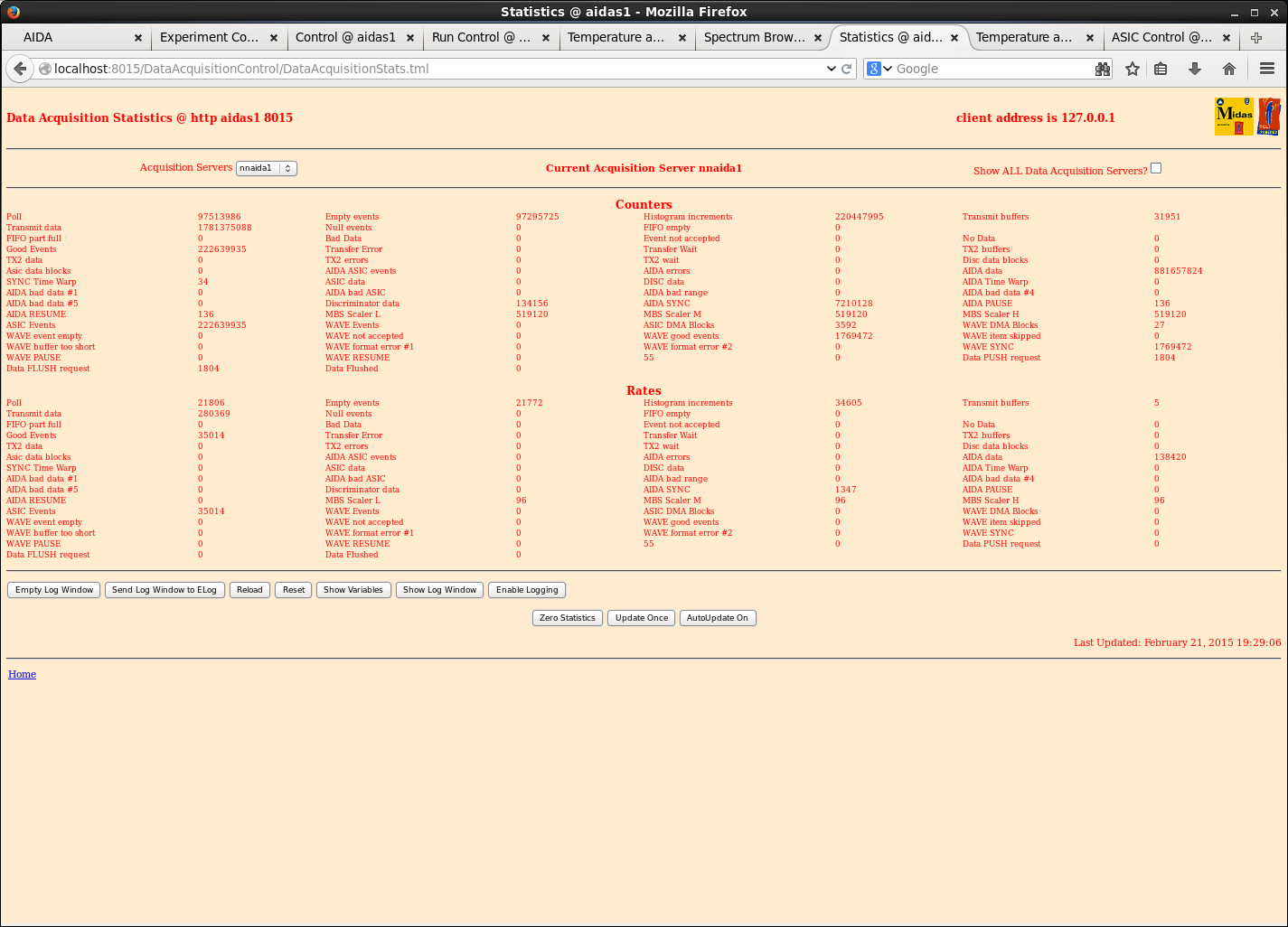
With the threshold at 0x10, the data rate show on the TapeServer window was ~3Mb/s (uncompressed?).
This was with 1 detector (BB18 2977-20) connected to 4 FEE64s with above settings, a 25Hz pulser and 241Am+207Bi sources (activities in ELog entry 40).
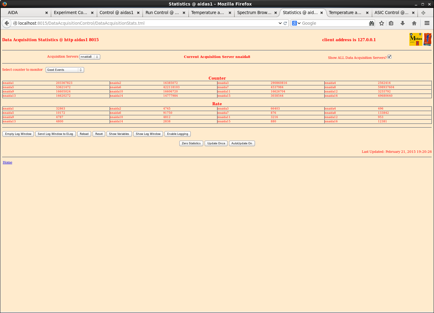
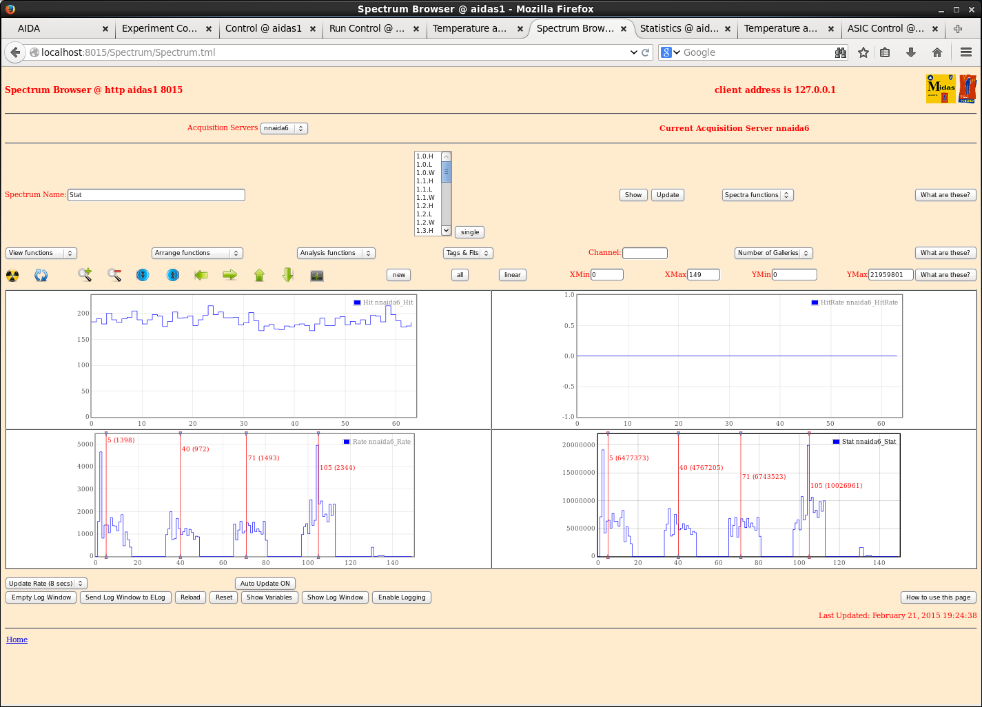
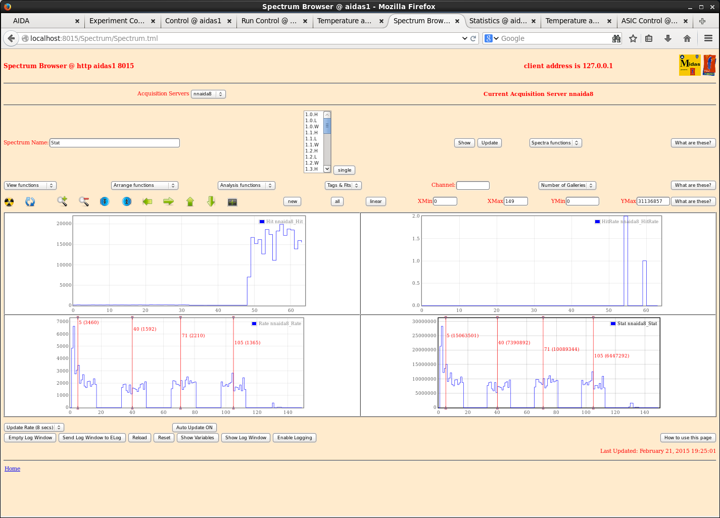
The Good Events rate averaged around 30,000-60,000/s per FEE64 card, with only a few Pause/Resumes coming through.
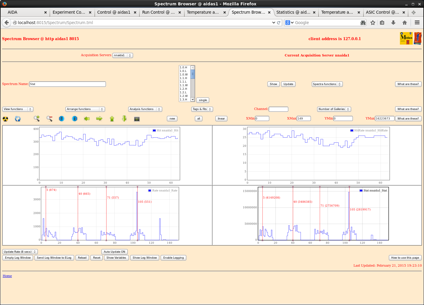
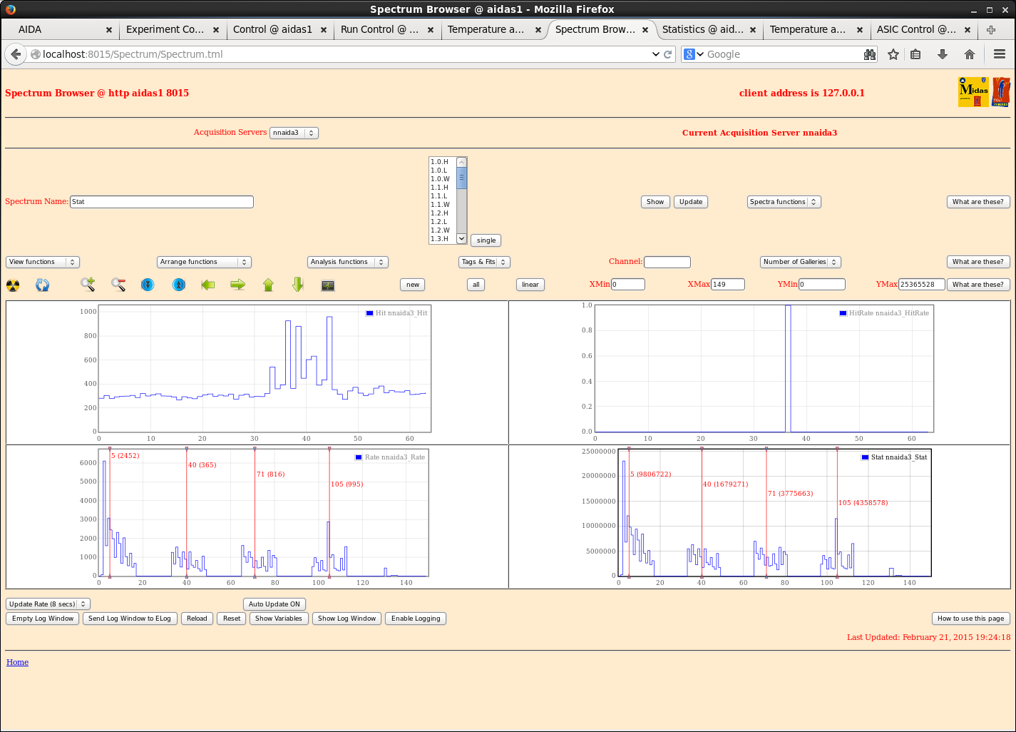
Example stats screen and hit patterns included below for final configuration. |
| Attachment 1: 21Feb_allStats.png
|
|
| Attachment 2: 21Feb_nnaida1_hits.png
|
|
| Attachment 3: 21Feb_nnaida3_hits.png
|
|
| Attachment 4: 21Feb_nnaida6_hits.png
|
|
| Attachment 5: 21Feb_nnaida8_hits.png
|
|
| Attachment 6: 21Feb_nnaida1_stats.png
|
|
|
44
|
Sun Feb 22 06:47:23 2015 |
CG, AE, TD | Sunday 22 February 2015 |
22/02/15
am Testing various grounding configurations for the connection between the DSSSD and the FEE64 modules.
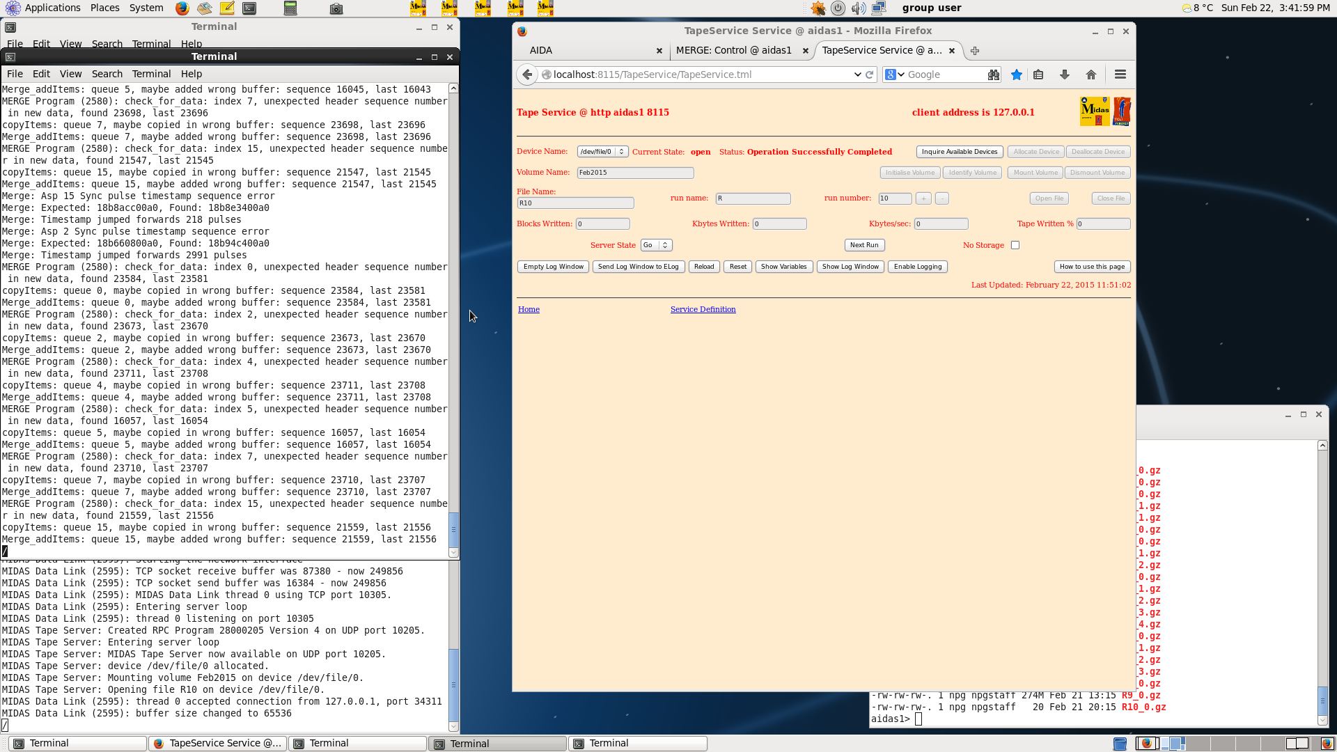
15.45 Obtaining error messages from Merger TTY console (see attachment 1)
1700: Summary of AM testing of grounding configurations.
Set up system as it was when we left last night to check reproducibility -> peak FWHMs all same to within 10%.
Throughout tests yesterday, nnaida8 was consistently worse than the other nnaida, why? Can it be improved?
Most obvious difference between 8 and the rest was that the nose was grounded through nnaida8.
Removed nose grounding cable and left to hang -> no appreciable difference in FWHMs.
It was then attached to the Cu piping using a croc clip -> no change.
Connected to nnaida6 -> no change.
The heavy duty Cu braiding was removed from all nnaida and the pulser FWHM in all nnaida increase significantly.
=> clearly the braiding is helping.
Put Cu braiding back in place and added shielding plates to nnaida1,3,8 (kapton in way on nnaida5/6, also useful as a reference point).
Each shield plate was fit onto the set screws with two spacers and sat over the kaptons, black tape was put over the vias to prevent them touching the plates.
No change with respect to the first measurements this morning.
=> the grounding changes implemented today have had no effect at the current noise level, but that is not to say they may not have an effect in combination with production detectors, new kaptons etc.
1715: Tested the new USB mains power switches for function (without load). All seem to function correctly and are controllable from the RPi.
|
| Attachment 1: Screenshot.png
|
|
|
45
|
Mon Feb 23 07:03:10 2015 |
TD, AE & CG | Monday 23 February 2015 |
14.30 Saved nnaida1-16 ASIC + Waveform configurations to directory (Data Base Key)
2015Feb23-12.11.40
(directory aidas1:/MIDAS/DB/EXPERIMENTS/AIDA/2015Feb23-12.11.40)
nnaida 1-2, 5-6, 9-10, 13-14 positive input ( front p+n junction strips )
nnaida 3-4, 7-8, 11-12, 15-16 negative input ( back n+n ohmic strips )
Standard ASIC configurations except
- shaping time 0xb (6,5us)
- peaking time 0x8 (16us)
- slow comparator 0x10 (~160keV)
- fast comparator (LEC/MEC) 0xff
- fast comparator (HEC) 0xff
nnaida 1-2, 5-6, 9-10, 13-14 negative input ( AIDA ASIC preamp output inverts input,
i.e. preamp with positive input produces negative input for sampling ADC )
nnaida 3-4, 7-8, 11-12, 15-16 positive input
Standard Waveform configurations except
- threshold 1000
- pre-trigger 0x100
- all channels disabled
2015Feb23-12.11.40 is now the default configuration file
Note: The directory (Data Base Key) which will contain the saved settings is created uid: npg, gid: npgstaff, perms 755.
However, its contents are written uid: nfsnobody, gid nfsnobody, perms 777. The default directory (Data Base Key) permissions
do not work - it is necessary to change the directory (Data Base Key) to perms 777 after its creation and before saving the
individual FEE64 configuration directories/files to it.
|
|
46
|
Mon Feb 23 07:23:08 2015 |
J. Agramunt, H. Baba, A. Estrade | DAQ correlation test |
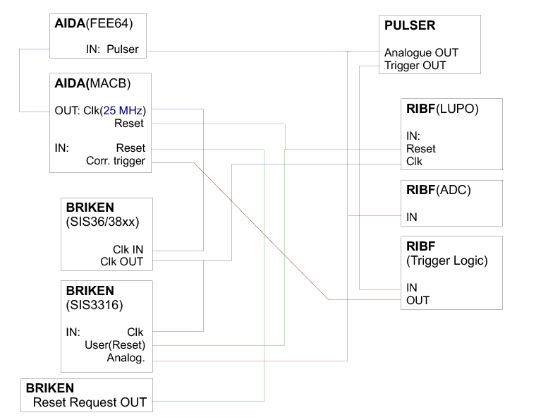
The attached figure shows the configuration used to test the synchronization of the DAQ systems using a
correlation scalar counted from a common clock signal (DAQcorrelation_diagram.pdf).

The chosen solution was to use a 25 MHz clock generated by the MACB modules of AIDA, which was distributed to
the other two systems by a SIS36/38xx module in the BRIKEN VME crate.

The correlation can be monitored online using the MIDAS DataXfer and DataSpy libraries
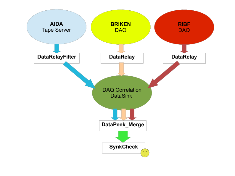
(http://npg.dl.ac.uk/MIDAS/DataAcq/Data.html). Each system operates a
DataRelay program that sends a data stream consisting only of IDs and time-stamps to a common DataSink (this
requires a DataRelay code that does some filtering of the raw data for each system). The scheme is shown in
attached diagram (DAQsoftware.pdf).

The DataPeek_Merge and SyncCheck codes use C++11 for parallelization of tasks, which is a helpful feature to
improve the efficiency of finding coincidences between the correlation pulses. Thus, the code will not run in
PCs with any Linux version. For example, it requires version 7 of ScientificLinux, which installed in the PC
being used for BRIKEN DAQ control that will stay at RIBF for the time being.


++ SYNCHRONIZATION RESULTS ++

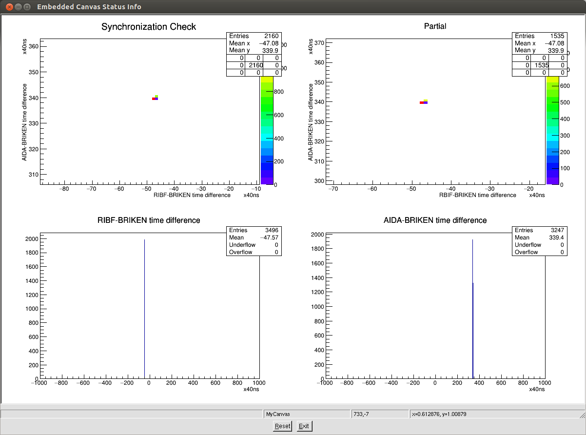
The figure correlation_25Hz.png shows a correlation plot for the BRIKEN+RIBF+AIDA running with correlations done
by a pulser at 25 Hz. A large fraction of the pulsers appear in the double-coincidence plots (top row; same plots,
except the 'Partial' one is automatically cleared every ~10seconds).

The bottom plots show the pair-wise correlations between BRIKEN and RIBF or AIDA. BRIKEN was defined as the
'master' in this test, but current version of the program is flexible to select any stream as the master one.

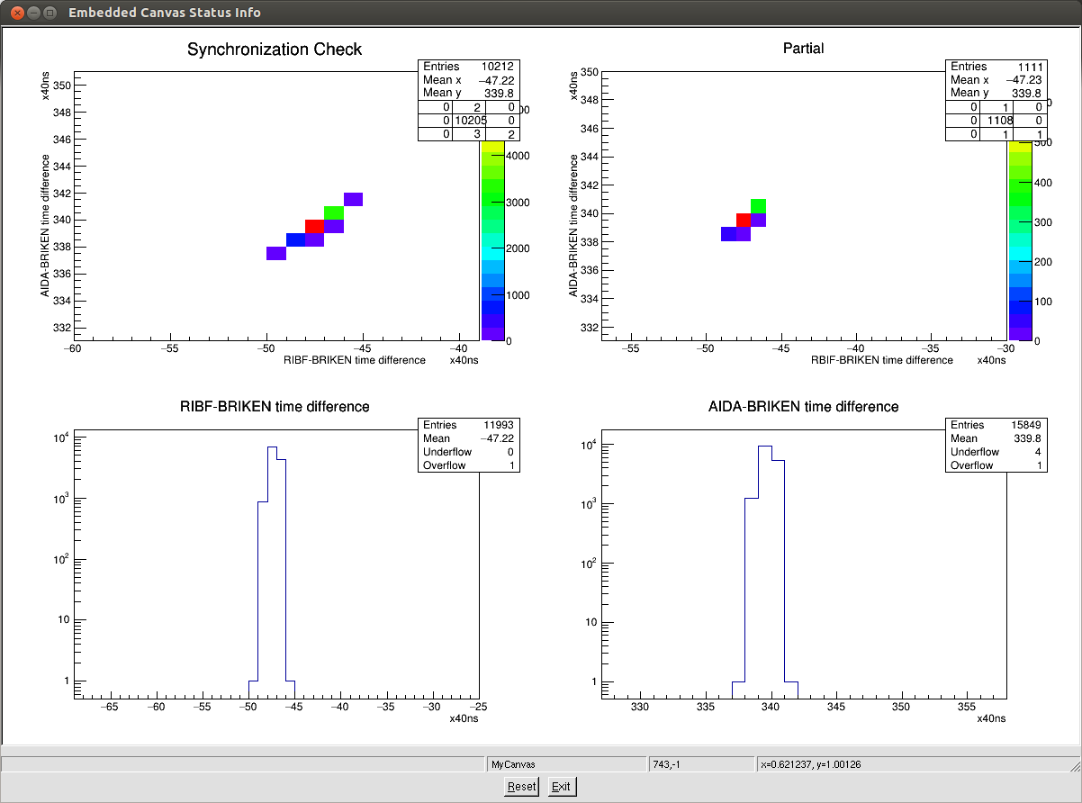
The second figure (correlation_random.png) shows the same test, but using a non-periodic pulser to trigger the
correlation scalar. We observed the same level of synchronization (peaks look brader just because of the zoom level). |
| Attachment 1: DAQcorrelation_diagram.pdf
|
|
| Attachment 2: DAQsoftware.pdf
|
|
| Attachment 3: correlation_25Hz.png
|
|
| Attachment 4: correlation_random.png
|
|
|
47
|
Mon Feb 23 11:10:44 2015 |
TD | Outline test plan - RIKEN - Feb 2015 |
With the exception of one AIDA FEE64 PSU configuration test (5) and the upgrades
of the AIDA FEE64 firmware (8) and MIDAS DAQ software (9) we have now completed all
of tasks described in the outline plan. |
| Attachment 1: RIKEN_test_-_Feb_2015.txt
|
Outline test plan - RIKEN - Feb 2015

1) Move Julabo FL006 recirculating chiller (plus ac mains transformer)
   and AIDA assembly stand into position.

   Consult Shunji Nishimura
   If we move equipment for the test, do we have to move it back before we leave?

2) Check 3-phase connection to ac mains transformer. Check chiller POST.

   TD - upload images from April/May 2014 to Elog

3) Re-connect Julabo FL006 recirculating chiller to AIDA assembly.
   Inspect coolant loop. Check coolant levels. Start chiller.
   Inspect for leaks. Check coolant levels.

4) Replace faulty USB-controlled ac mains switch. Test operation with
   FEE modules disconnected.

5) Connect 8x FEE modules to ?x FEE PSUs.

   PCS - default initial configuration?

6) Check MACB cabling. Power up 8x FEE modules.

7) Check setup & configuration (ASICs, FEE64).
   Default ASIC parameters (tau = 2us). Waveforms off.

8) Test FEE64 performannce with pulser and no input load.
   Expect pulser peak width < 15 ch FWHM.

*** Status quo ante re-established ***


Test 1

1) Install 1x MSL type BB18-1000 DSSSD with 3x modified 0.9m Kapton PCBs
   plus 1x unmodified 0.9m Kapton PCB. Install 207Bi source.

2) Bias DSSSD using Silena 7710 Quad Bias Supply (ground referenced bias)
   and confirm stability problems observed April/may 2014 are still present.

Test 2

1) Bias DSSSD using CAEN N1419B (floating bias) and confirm stability problems
   improve. Assess impact of preAmp reference setting - if possible, proceed
   with default setting.

2) Test FEE64 performance with pulser.
   Expectation pulser peak width < 120-150 ch FWHM.

Test 3

1) Adjust FEE64 PSU voltage levels per procedure described by PCS.

2) Test FEE64 performance with pulser. Compare to previous test.

Test 4

1) Attach heavy-duty grounding cable between FEE adaptor PCBs.

2) Test FEE64 performance with pulser. Compare to previous tests.

Test 5

1) Re-configure FEE PSU cabling per PCS request(s)

2) Test FEE64 performance with pulser. Compare to previous tests.

Test 6

1) Re-assess impact of preAmp reference setting.

Test 7

1) With optimum configuration obtain and analyse data files with pulser
   and 207Bi data.

Test 8

1) Update FEE firmware. Repeat test 7.

Test 9

1) Update MIDAS software. Repeat test 7.
|
|
48
|
Tue Feb 24 03:04:59 2015 |
CG, TD | Tues 24th Feb progress |
24/02/15
1200: Update the FEE firmware on nnaida1-16 without problem.
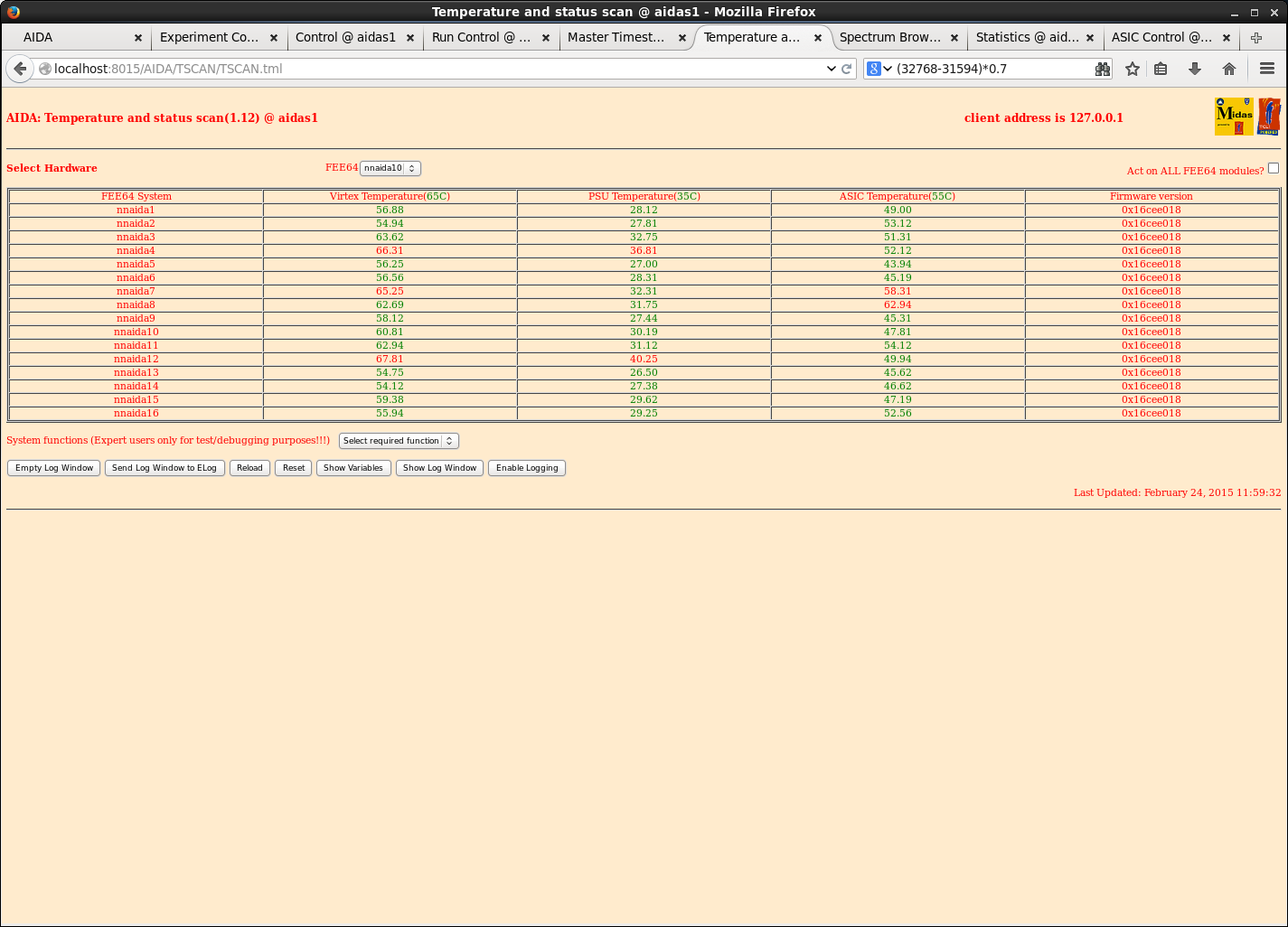
Gone from file FEE_Oct12_27Nov13.bin ----> FEE_Riken_Apr14_24.bin
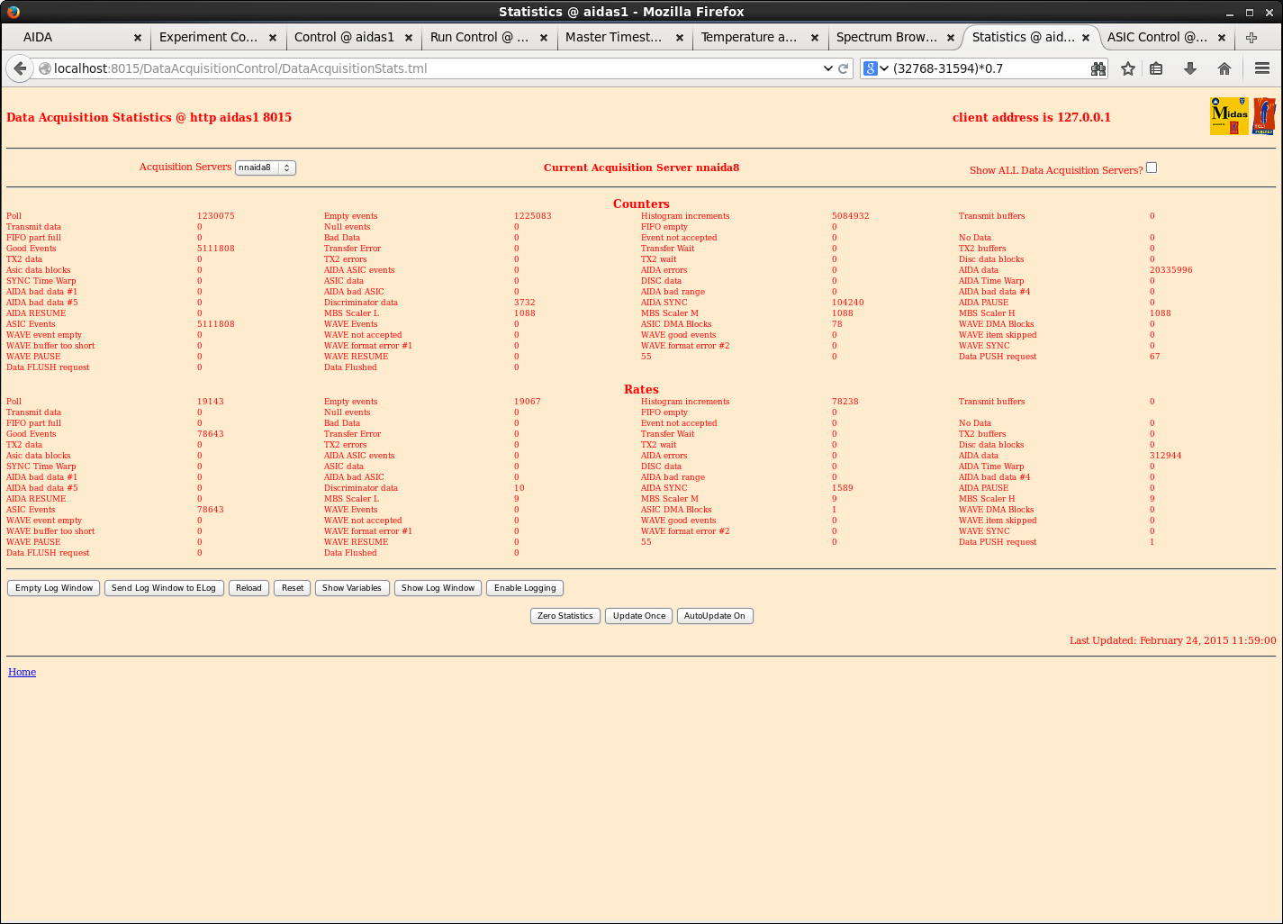
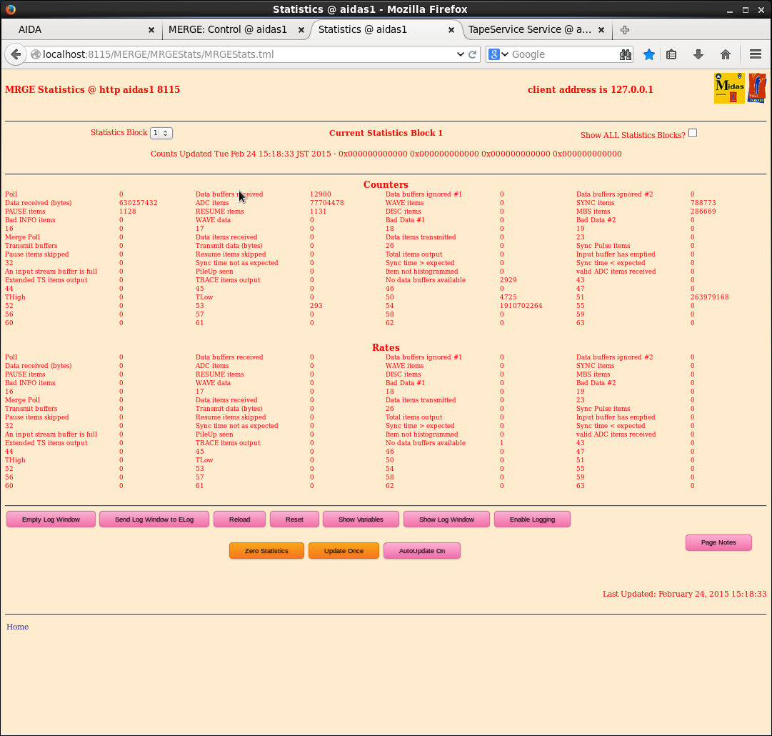
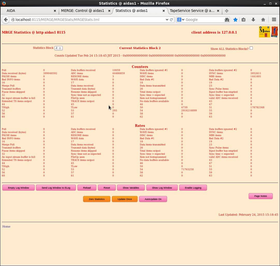
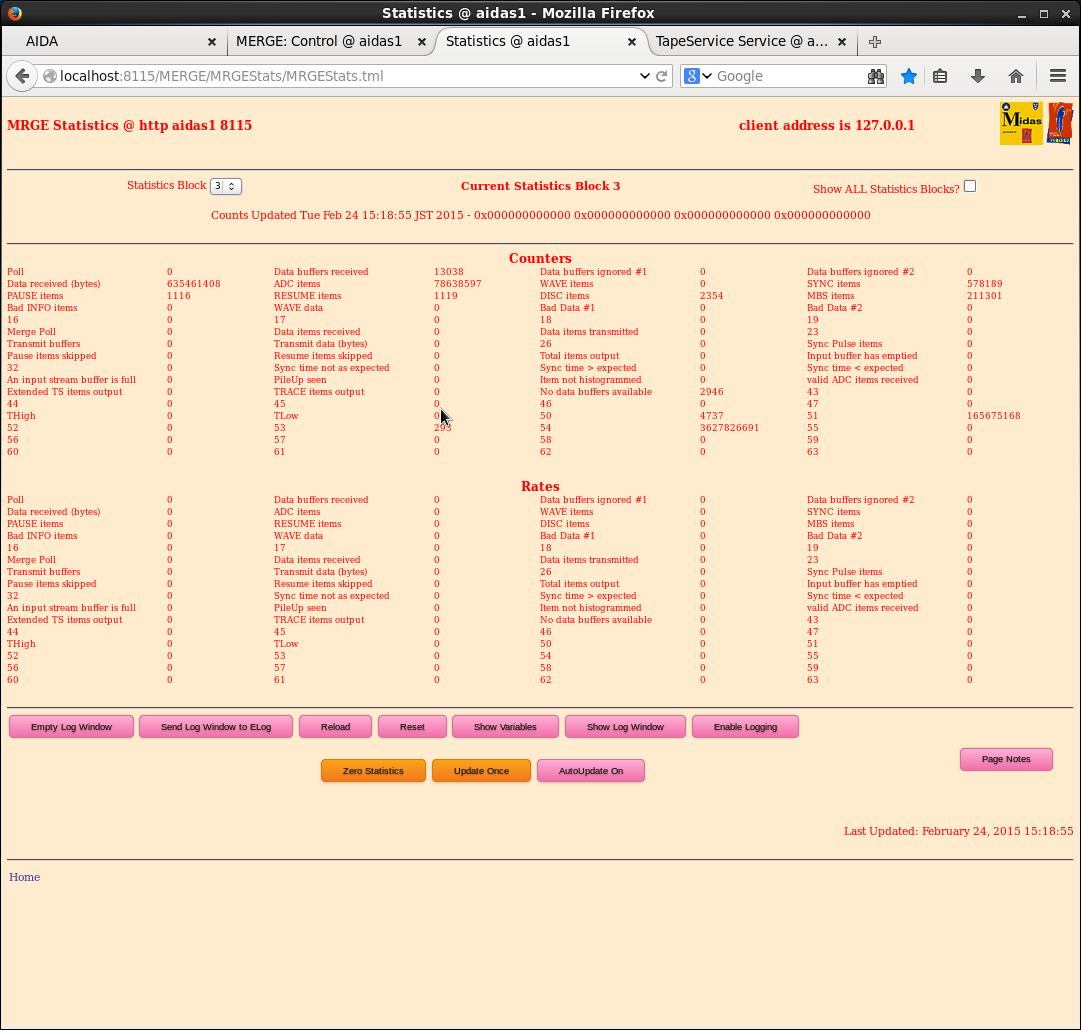
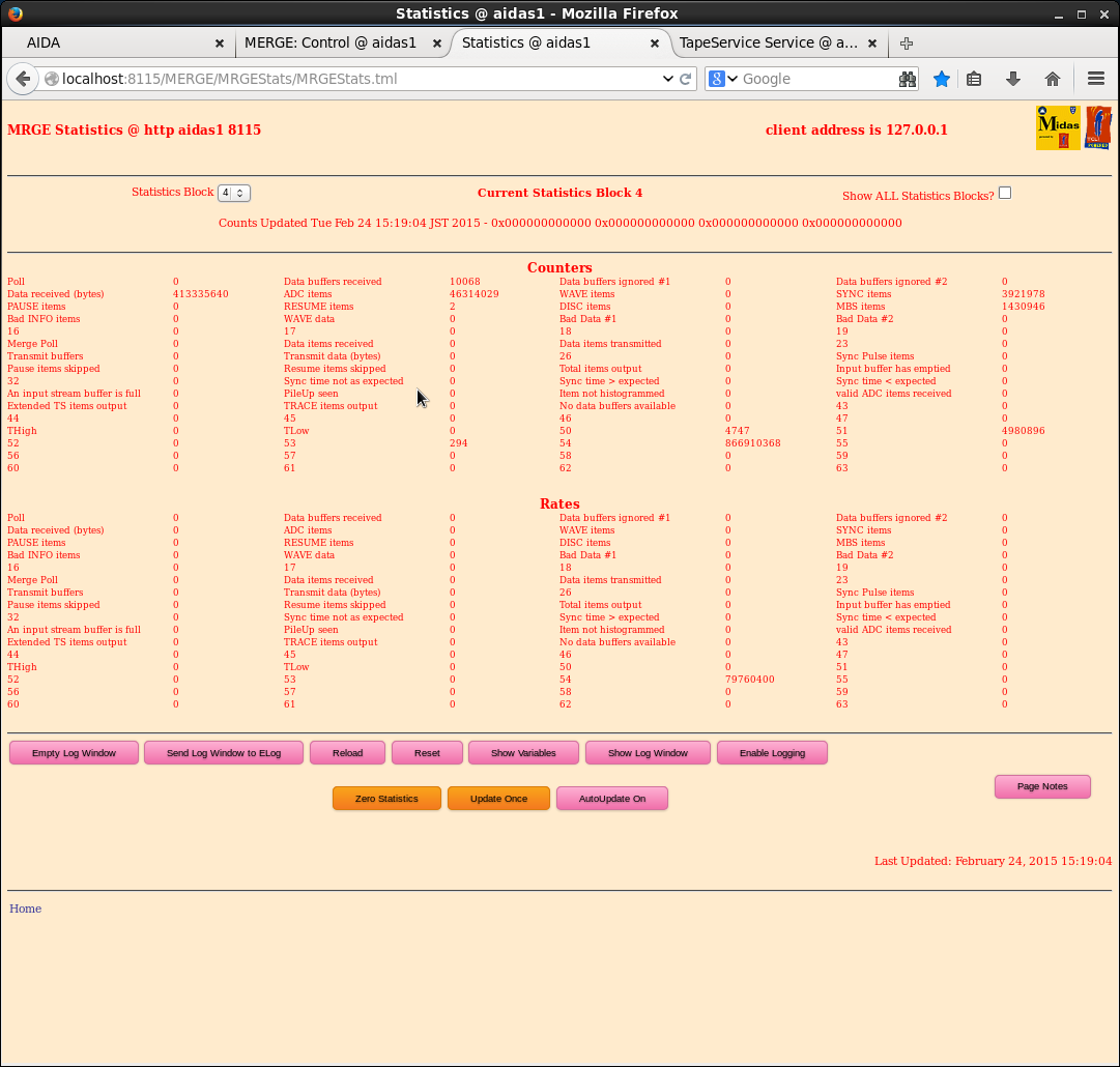
Included are a screen shot of the temperature window showing the new firmware versions and a stats screen.
12.15 Update MIDAS DAQ software
su
cp -r /MIDAS@aiidas /MIDAS@aidas.240214 ( /MIDAS is a link to /MIDAS@aidas )
exit
cd <update directory>
cp -r Data_Acq /MIDAS
cp -r Merger /MIDAS
cp -r TclHttpd /MIDAS
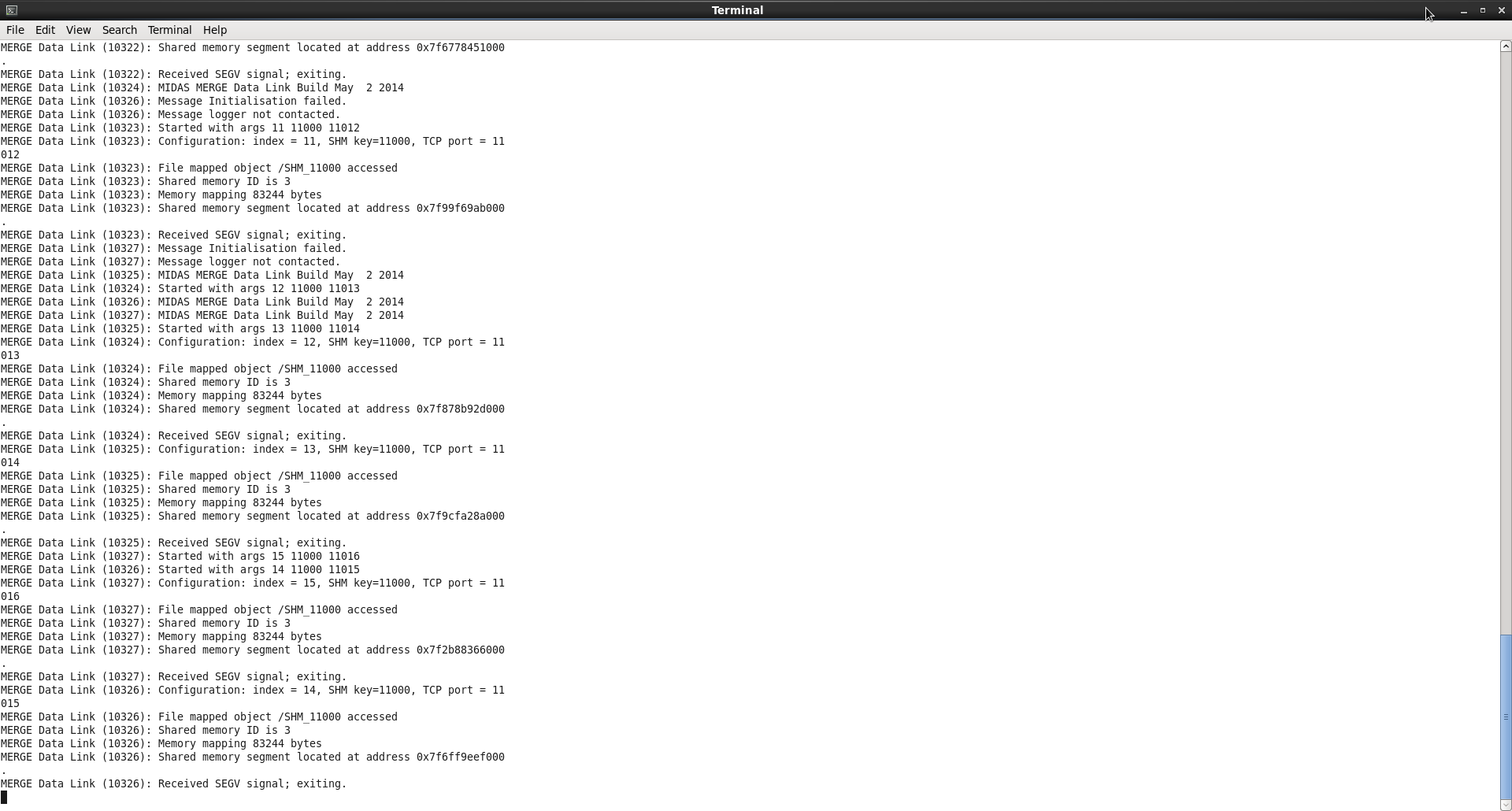
New versions of merge64.AD and master64 were installed in /MIDAS/Merger but the process crashed at startup
with multiple messages of the type:
MIDAS Data Link (12345) : Received SEGV signal; exiting.
(see attachment 3)
Is this related to the recent changes to the MIDAS TapeServer software to resolve problems with MIDAS Data
libraries libdataspy.so and libxfer.so ?
As a temporary workaround I have copied the backups of merge64.AD and master64 back to the install
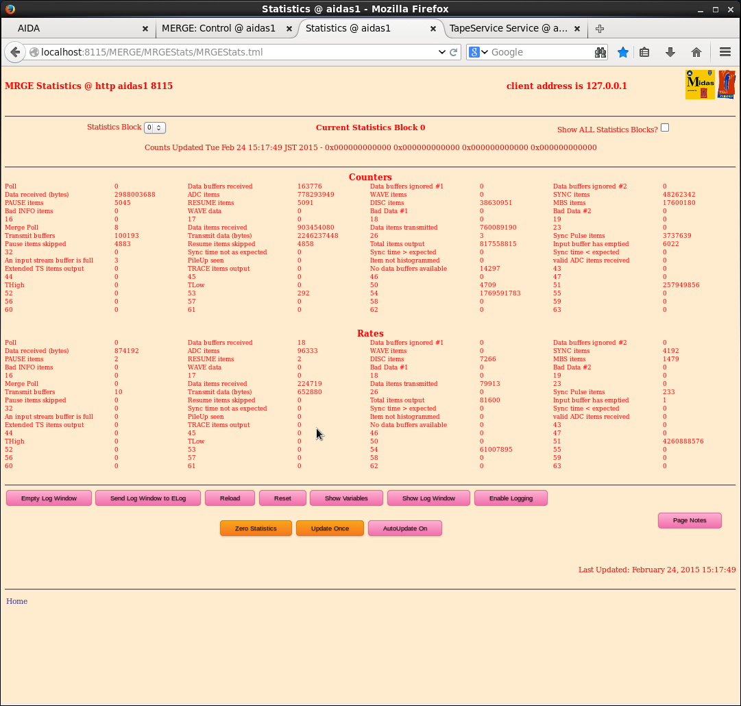
directory /MIDAS/Merger. With the old verison of the merger we continue to obtain error messages
(see attachments 4-8)
|
| Attachment 1: 24Feb_temps.png
|
|
| Attachment 2: 24Feb_allStats.png
|
|
| Attachment 3: 24Feb_mergerError.png
|
|
| Attachment 4: stats0.png
|
|
| Attachment 5: stats1.png
|
|
| Attachment 6: stats2.png
|
|
| Attachment 7: stats3.png
|
|
| Attachment 8: stats4.png
|
|
| Attachment 9: tty.png
|
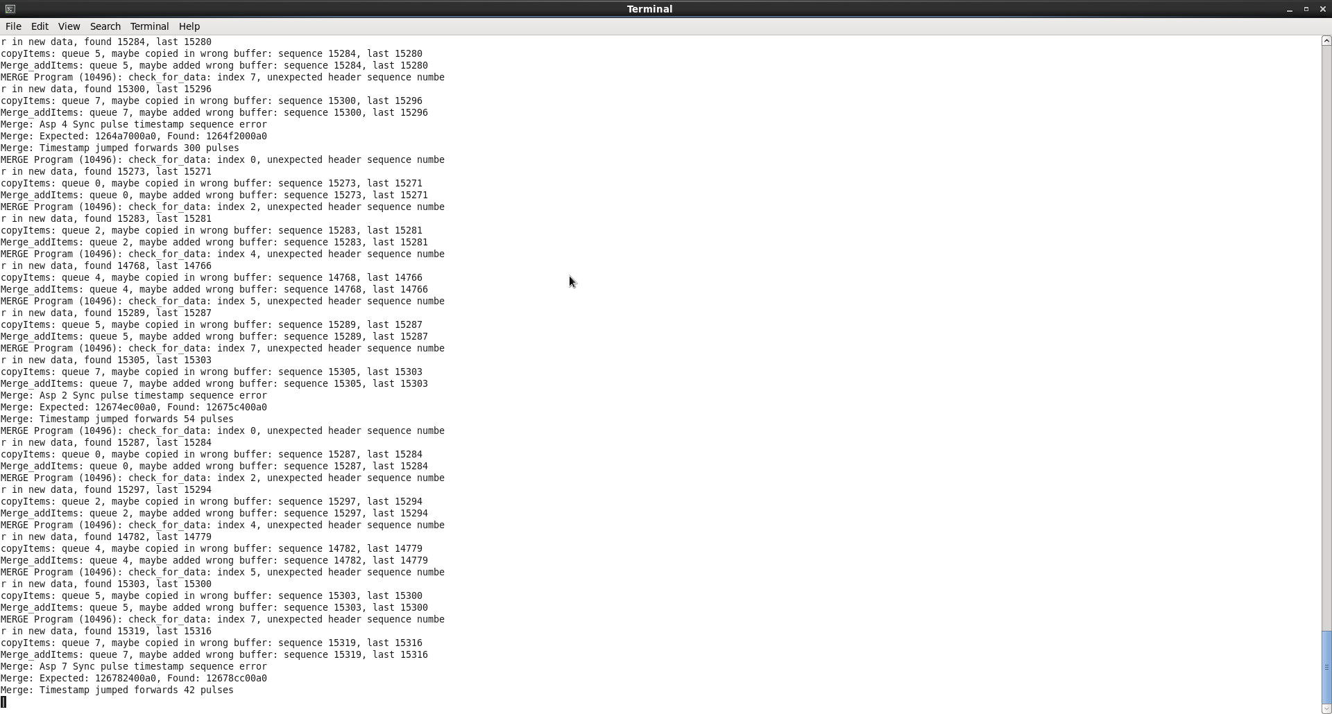
|
|
49
|
Wed Feb 25 09:59:28 2015 |
CG, AE | Weds 25th Feb progress |
25/02/15
1200: Swapped out old green power switch for new one from UoE (having previously tested them both yesterday and found them to work fine).
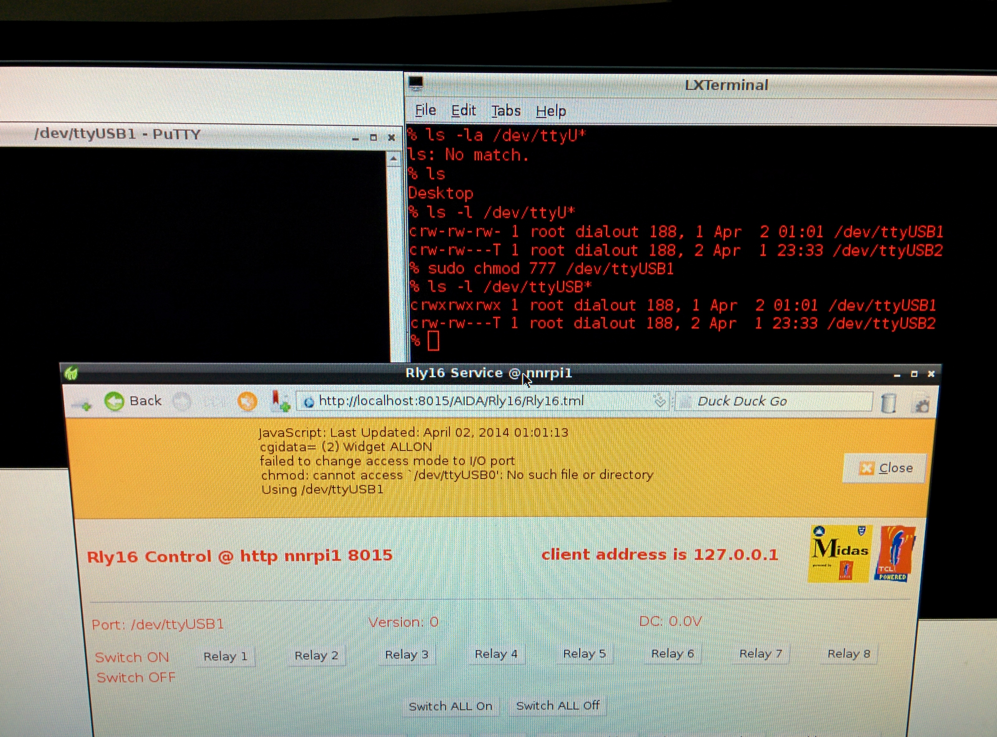
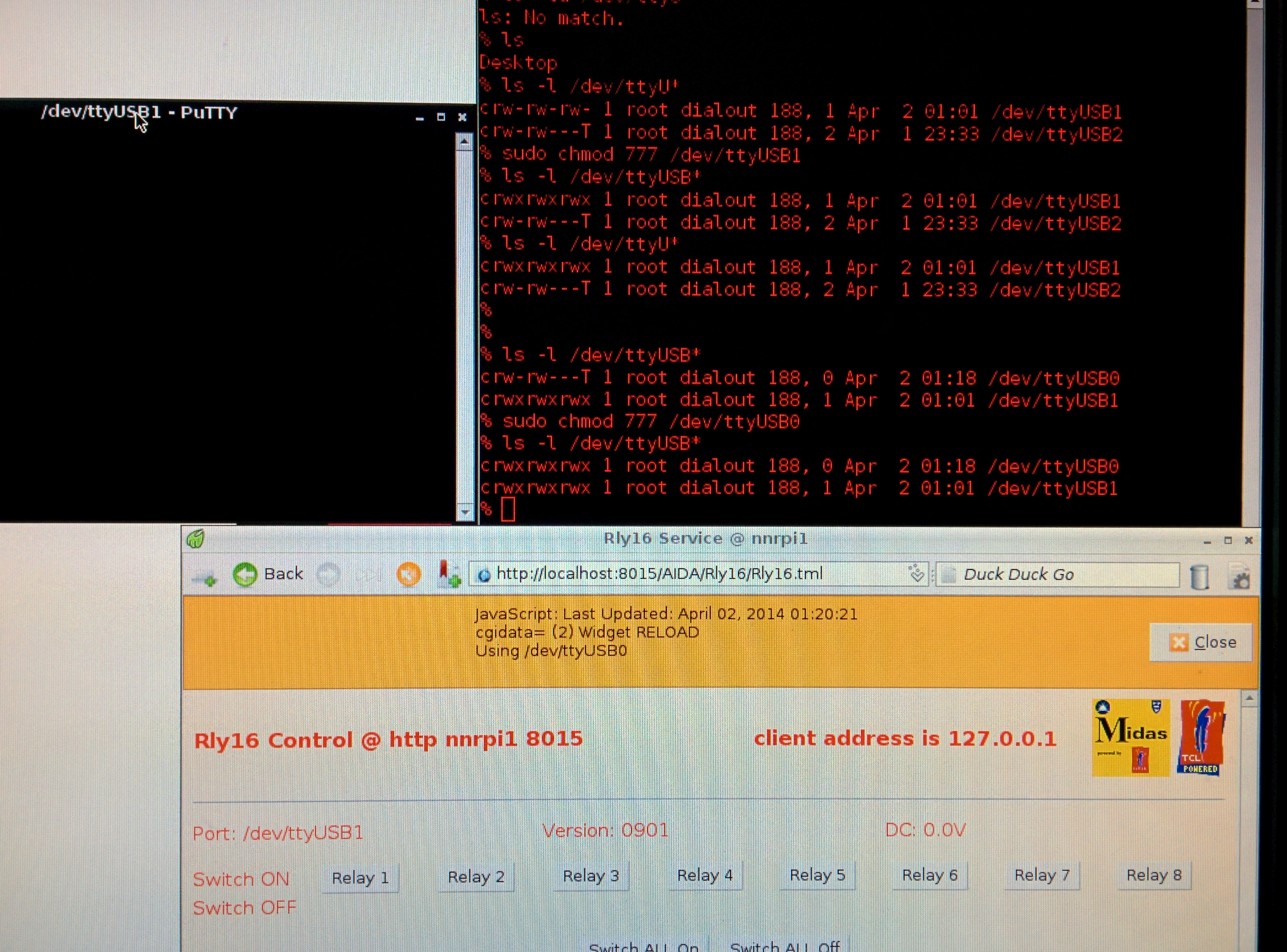
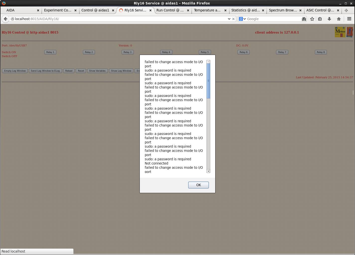
With first switch connected and PuTTY session opened cannot get RPi to connect to it. See (bodged) screen shots below.
Tried many permutations of trying to connect using ttyUSB0/1/2 with various permissions set, none yielded any results other than the error messages below.
1500: Swapped 1st UoE power switch out for the second. Plugged it straight in and it works... ???
Later unplugged it and when reconnected saw the same errors as before. We got rid of these by plugging in the USB cable once the unit was powered on. Does this make any sense, or was it just luck?
Carried out pulser walkthrough to file R22_0. Use same "best" settings as yesterday.
Changed polarity of detector bias (from -100V to +100) and observed a similar leakage current as previously (11.5uA) and normal rates/spectra for each detector. No obvious changes from -ve bias polarity. GOOD.
1830: Looked at effect of supplying each FEE64 from various power supplies (as per request PC-S email on Sun 22nd Feb).
Original configuration : | 1 2 | 4 3 | 5 7 | 8 6 | (all in one PSU)
Changed to: | 1 - | - - | - - | - - | PSU#1
| 3 - | - - | - - | - - | PSU#2
| 6 - | - - | - - | - - | PSU#3
| 8 - | - - | - - | - - | PSU#4
with PSUs #3+4 completely unplugged apart from nnaida6+8. In PSUs #1+2, the remainder of the slots were connected as previously (apart from for nnaida3,6,8, in which case they were swapped for another FEE64 at random).
Initially all PSUs were plugged into one half of the power switch, but the fuse blew. We replaced it with a spare fuse from the unused supply and distributed the PSUs 2 to each half of the switch.
This configuration yielded larger FWHM than original set up ---> worsened performance.
|
| Attachment 1: 2015-02-25_14.25.40.jpg
|
|
| Attachment 2: 2015-02-25_14.38.43.jpg
|
|
| Attachment 3: 25Feb_Rly16error.png
|
|
|
50
|
Wed Mar 4 17:38:06 2015 |
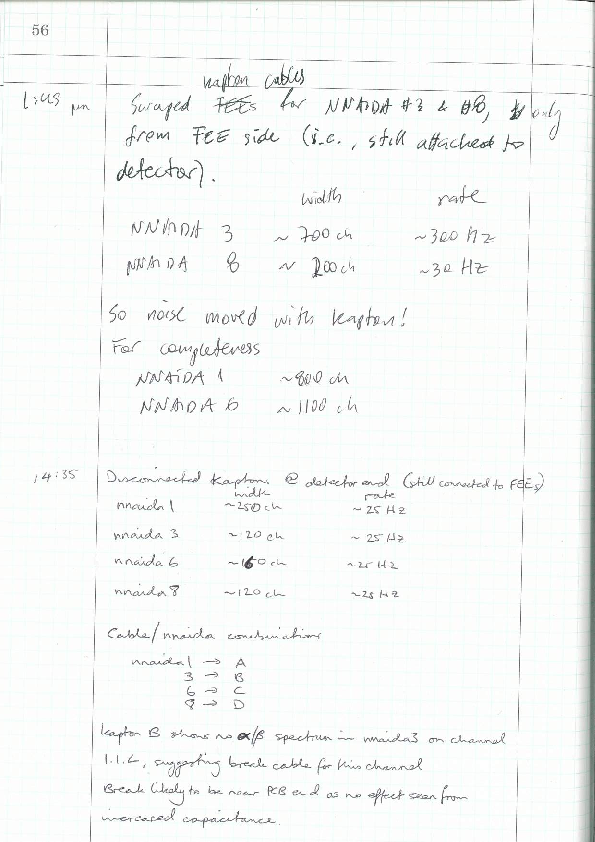
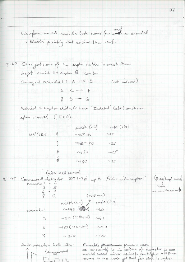
CG | Log book for Feb 2015 tests |
04/03/15
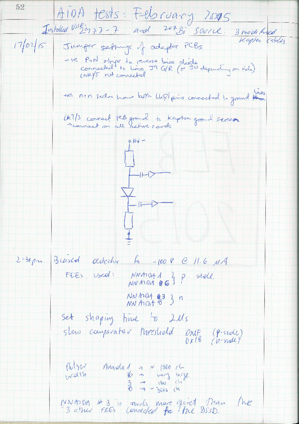
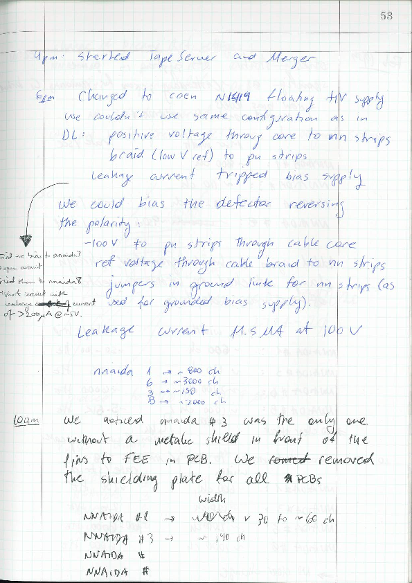
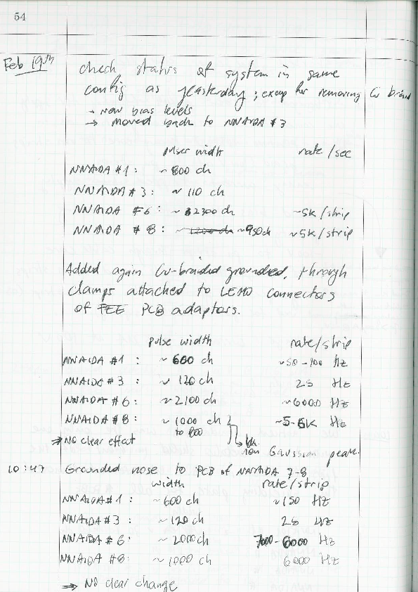
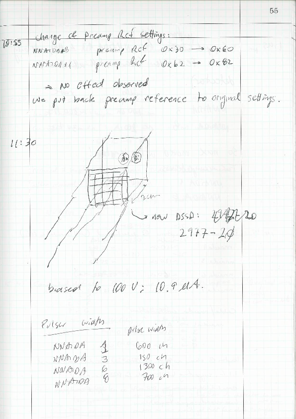
Please find attached a scan of the log book for the Feb 2015 AIDA tests at RIKEN. |
| Attachment 1: AIDA_Feb2015_labBook_comp.pdf
|


|
|
51
|
Thu Mar 5 12:11:44 2015 |
TD | To Do list - March 2015 |
A draft 'to do' list in preparation for further AIDA tests at RIKEN from mid-April.

Please feel free to add your comments, suggestions, other items etc.


High Priority

- [VP] fix problem with new merger program which crashes (SEGV) at startup
  see https://elog.ph.ed.ac.uk/AIDA/48

- [PCS/Edinburgh] fit 4x AIDA FEE64 PSUs with LCR filters and return to RIKEN

- [PM] transfer AIDA support assembly from original base to new RIKEN F11 base

Medium Priority

- [VP] TapeServer 'no storage' mode should not create files (cf. MIDAS VME DAQ TapeServer behaviour) ... ?

- [VP] TapeServer should check for existence of file before opening new file
  (and possibly overwriting an existing file) as a workaround for umode 022 file perms

- [VP] Define robust procedure for starting/stopping MIDAS DAQ/Merger/TapeService

- [VP/PCS] Critically review data synchronisation methodology
  see https://elog.ph.ed.ac.uk/BRIKEN/5 and https://elog.ph.ed.ac.uk/BRIKEN/6

Low Priority

- [Edinburgh] modify USB ac mains switches - relays default to off state - ship to RIKEN

- [Edinburgh] purchase 3x 3TB SATA disks for installation in aidas1 |
|
52
|
Mon Mar 9 09:02:03 2015 |
Patrick Coleman-Smith | Adding Filters to the AIDA PSU. |
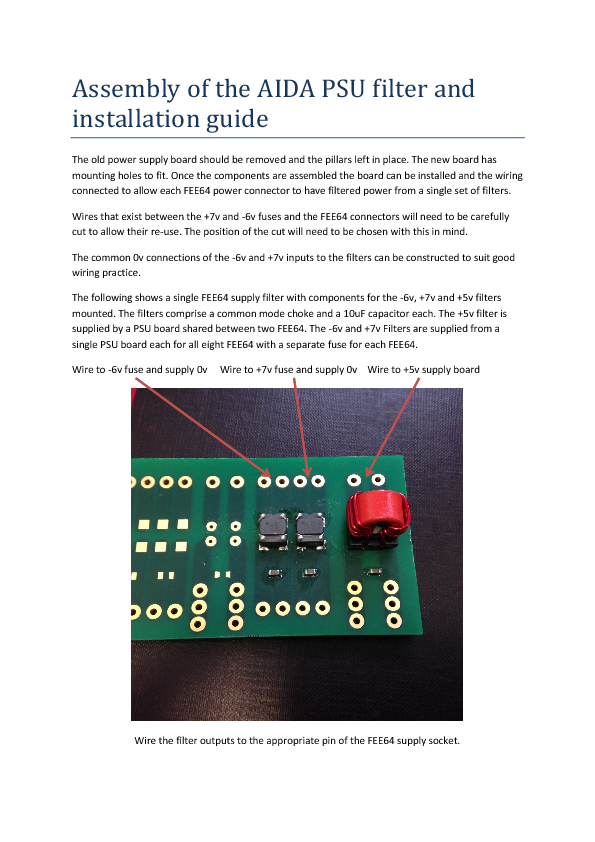
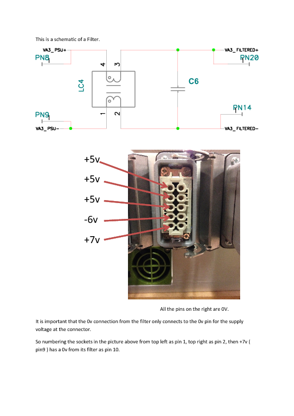
This guide is to help with the filter pcb assembly and installation into the AIDA power supply. |
| Attachment 1: Assembly_of_the_AIDA_PSU_filter_and_installation_guide.pdf
|
|
|
53
|
Mon Mar 9 13:59:32 2015 |
TD | New AIDA support frame for F11/F12 @ RIKEN |
|
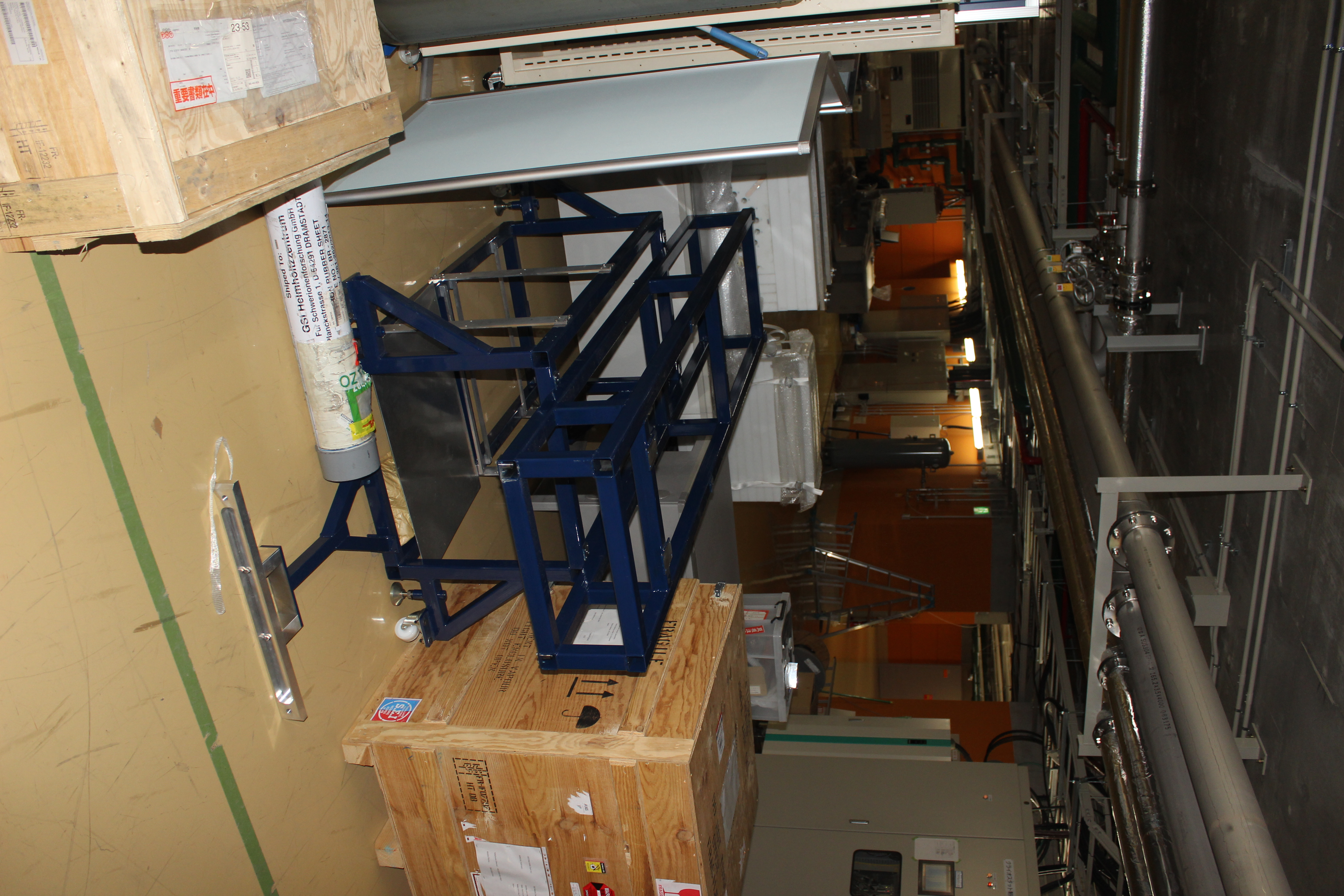
| Attachment 1: IMG_2798.JPG
|
|
|
54
|
Mon Mar 9 16:45:35 2015 |
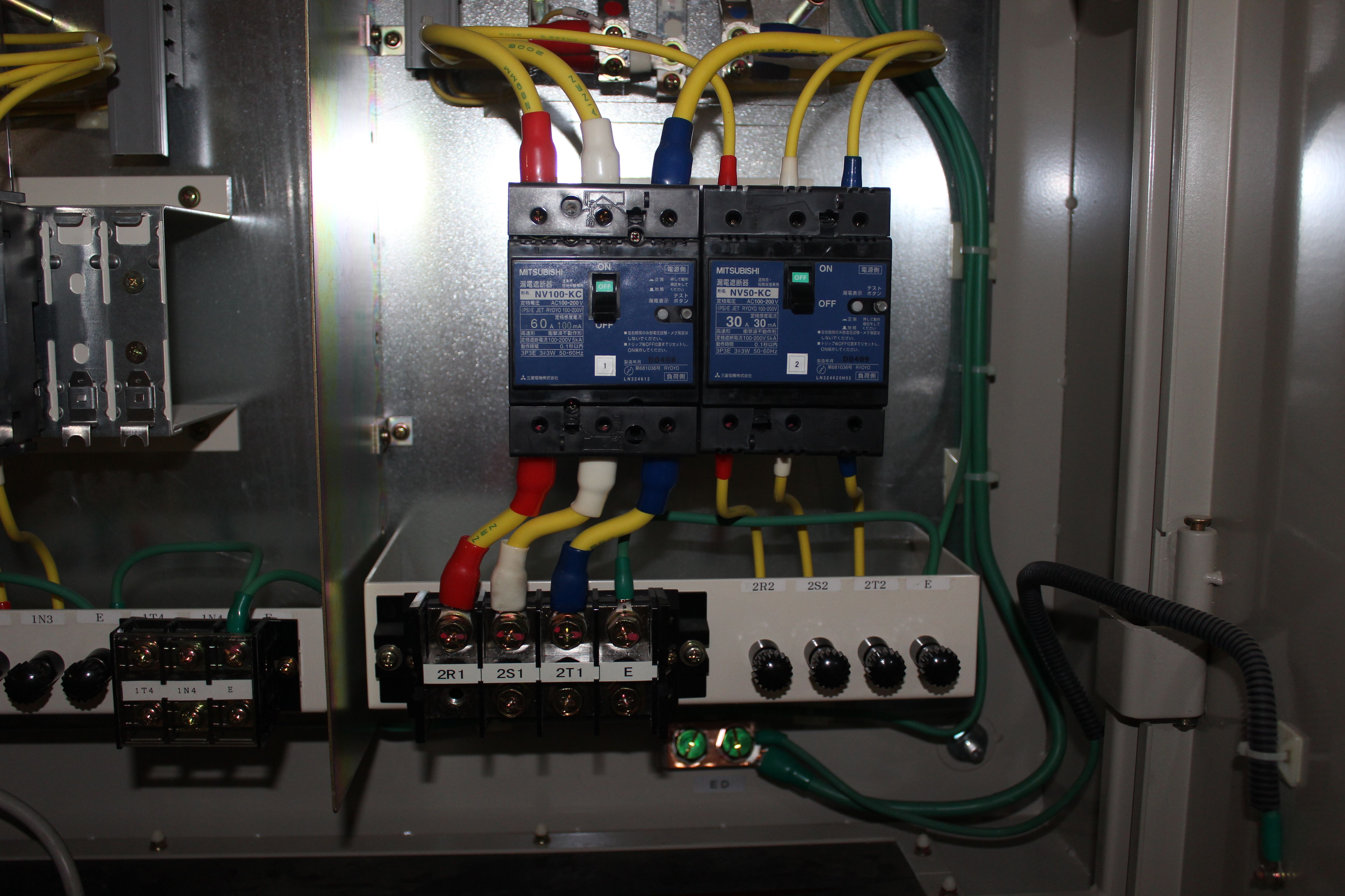
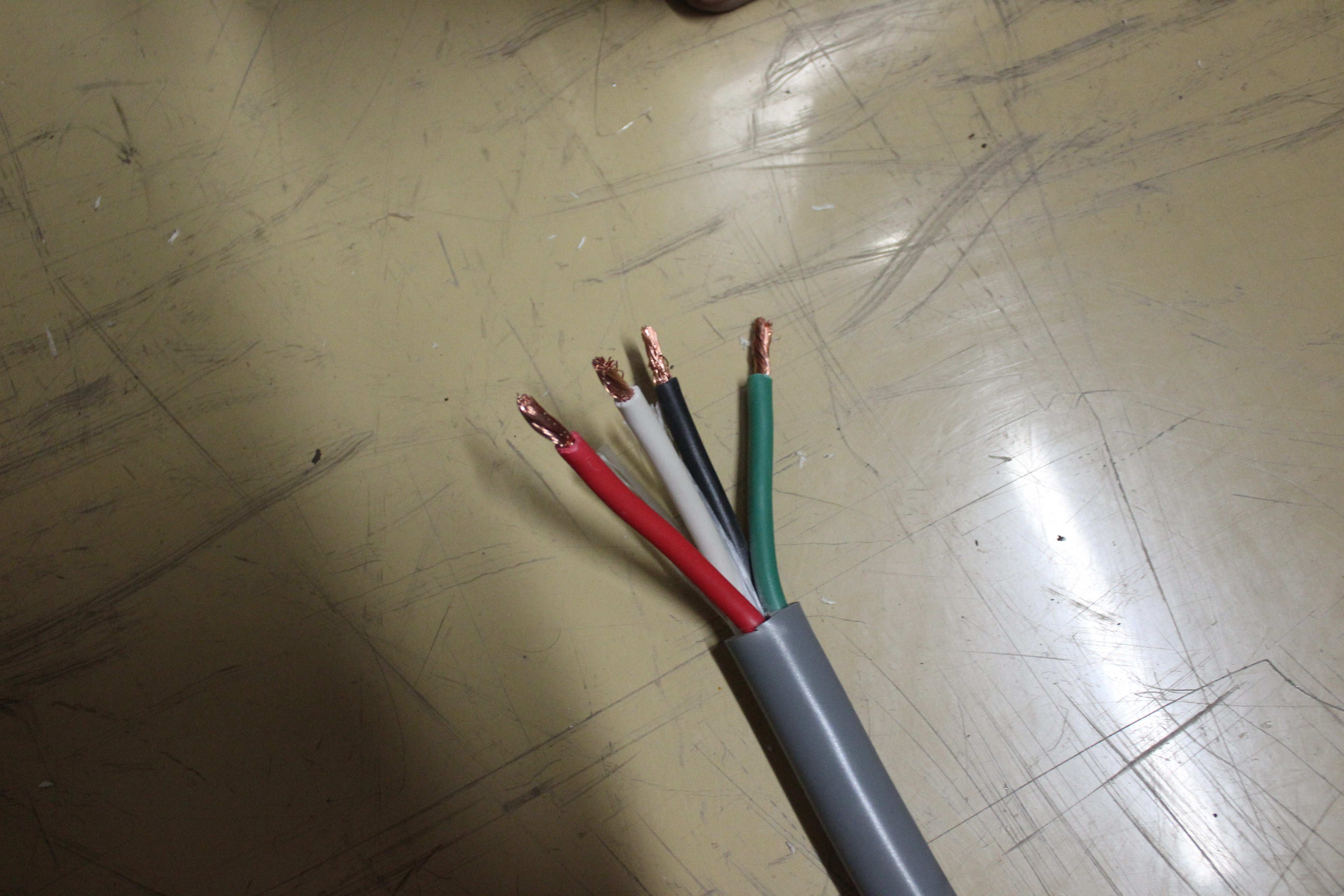
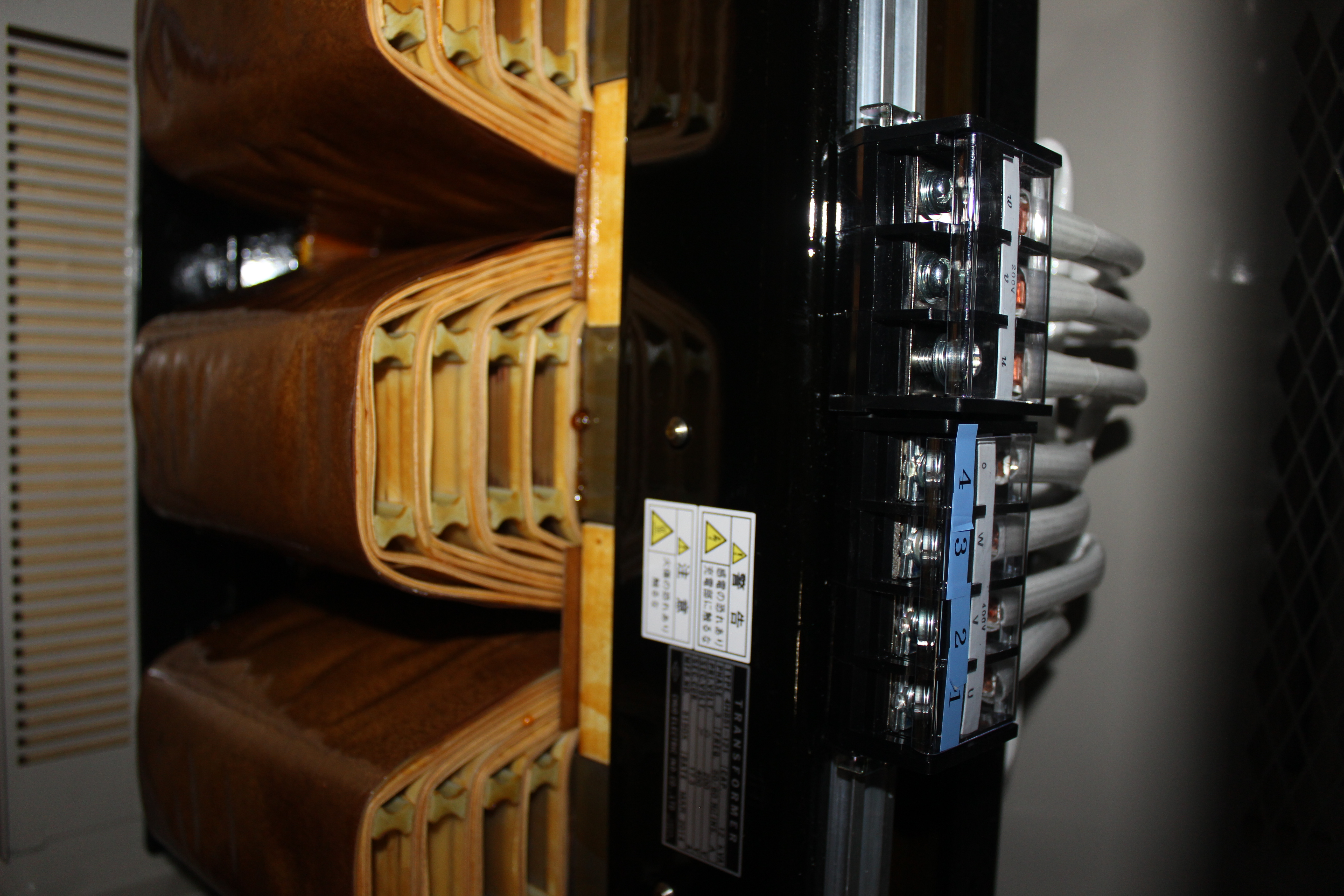
TD | Julabo FL11006 Recirculating Chiller: connection to 3ph ac mains |
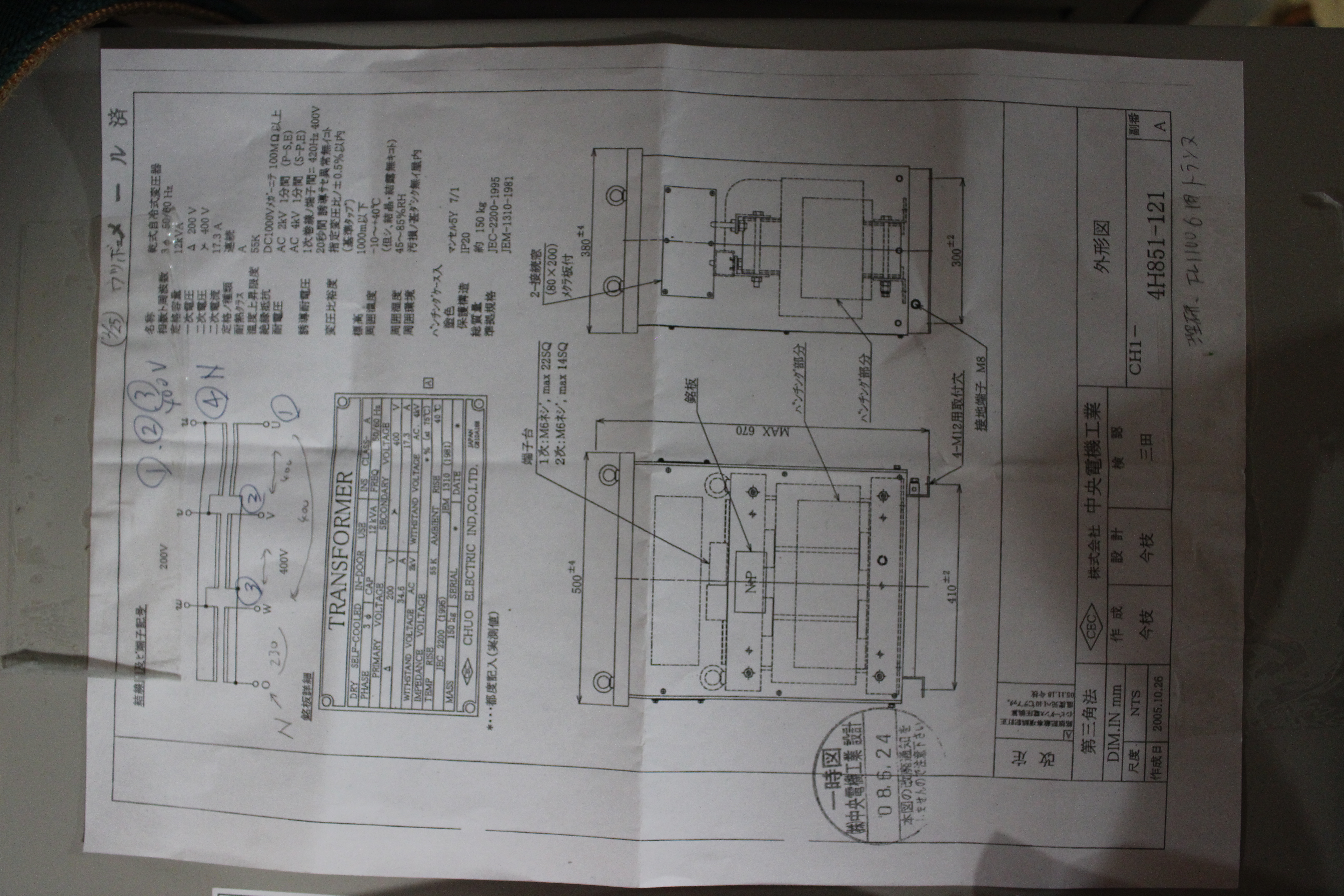
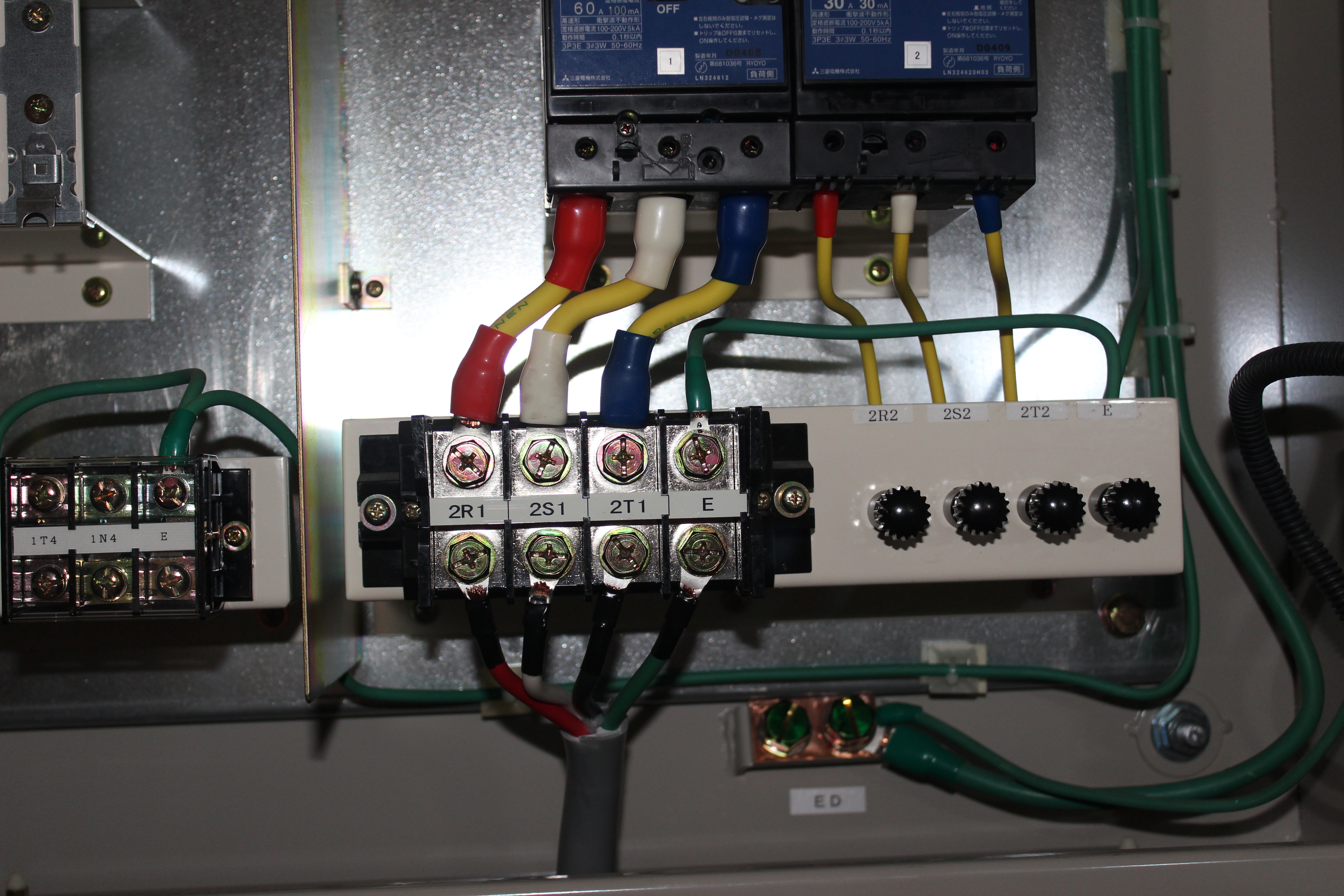
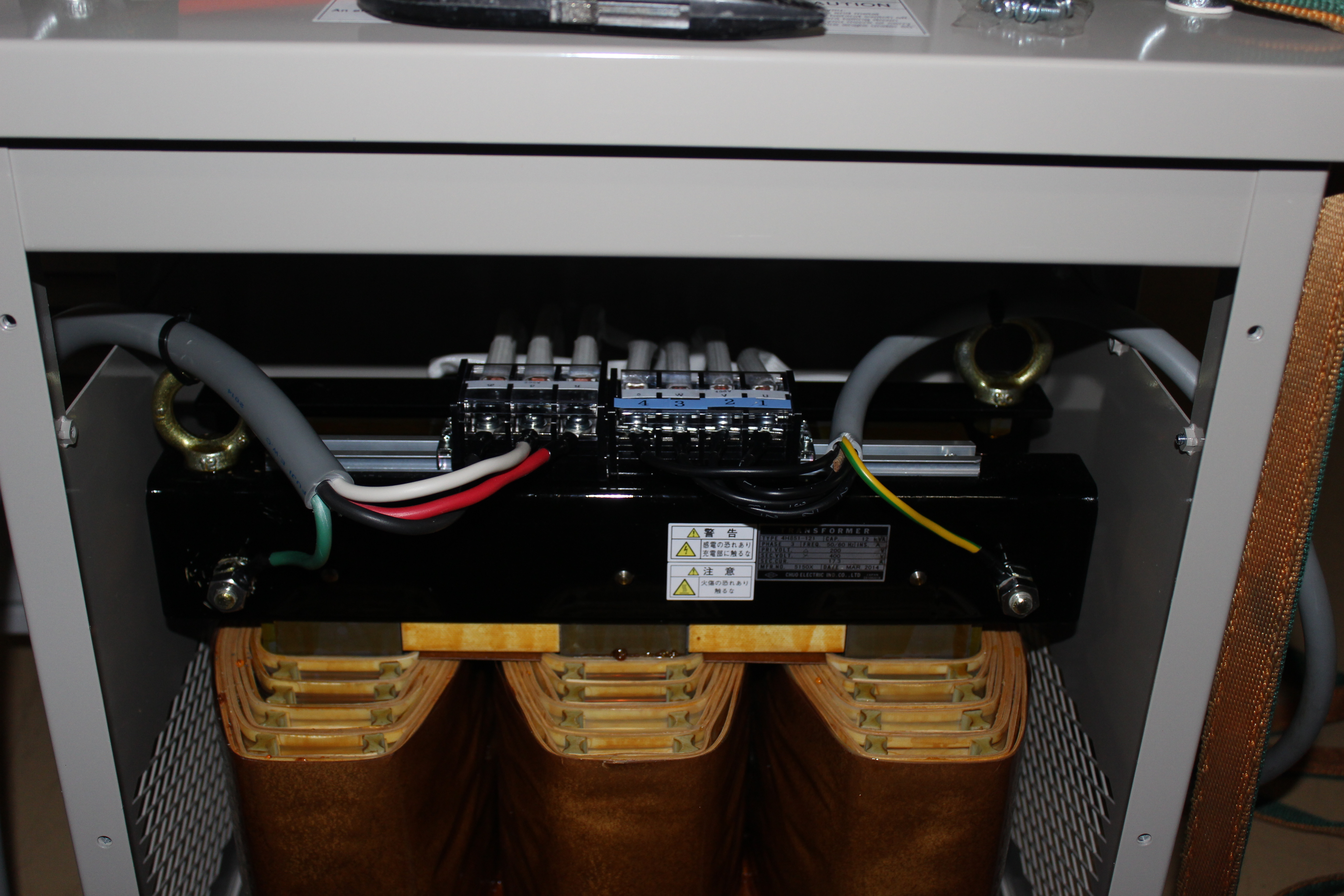
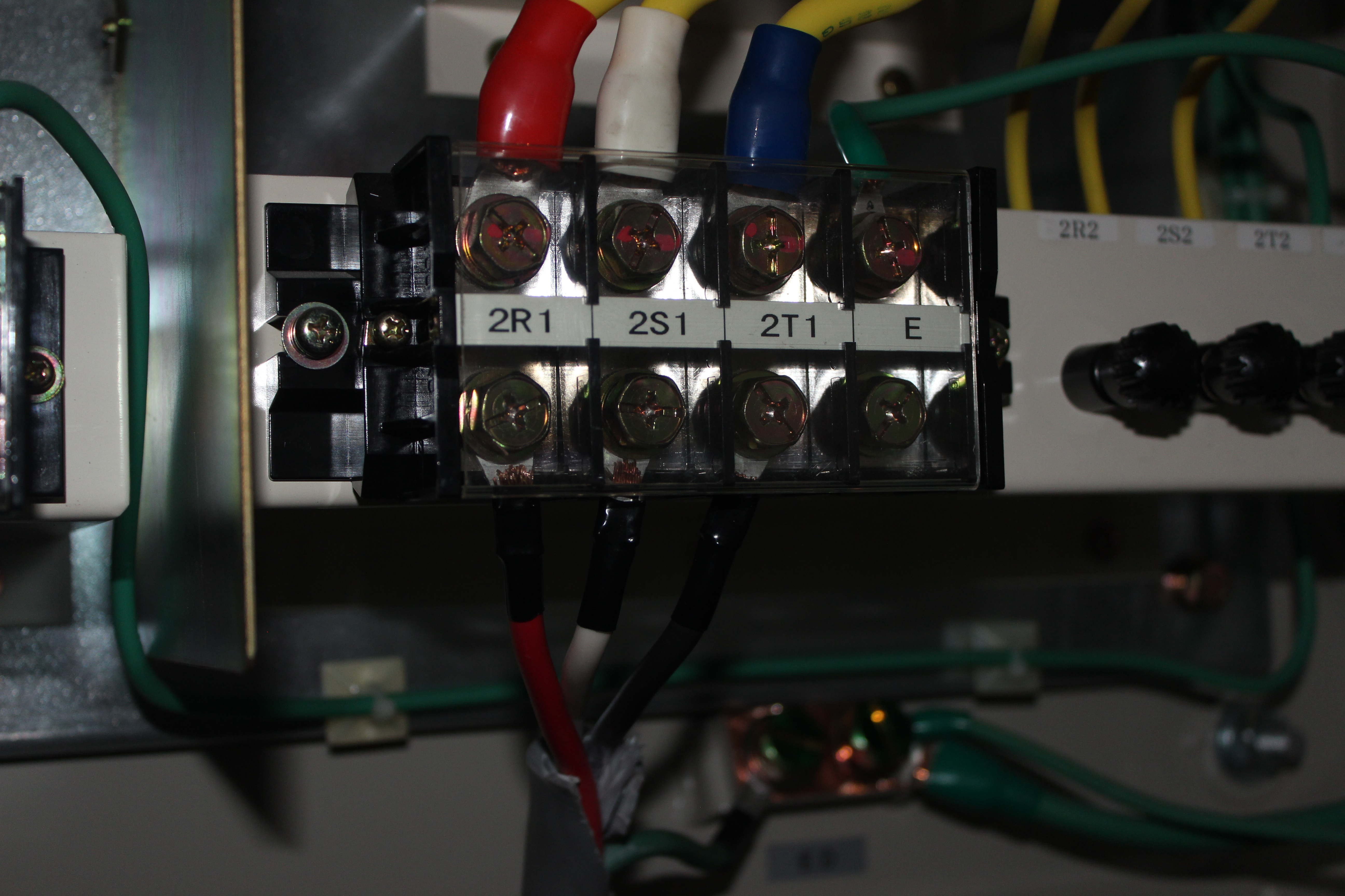
3ph 100VAC/50Hz to Julabo FL11006 3ph 230VAC/50Hz via local transformer |
| Attachment 1: IMG_2408.JPG
|
|
| Attachment 2: IMG_2409.JPG
|
|
| Attachment 3: IMG_2411.JPG
|
|
| Attachment 4: IMG_2413.JPG
|
|
| Attachment 5: IMG_2415.JPG
|
|
| Attachment 6: IMG_2419.JPG
|
|
| Attachment 7: IMG_2796.JPG
|
|
|
55
|
Mon Mar 9 16:51:26 2015 |
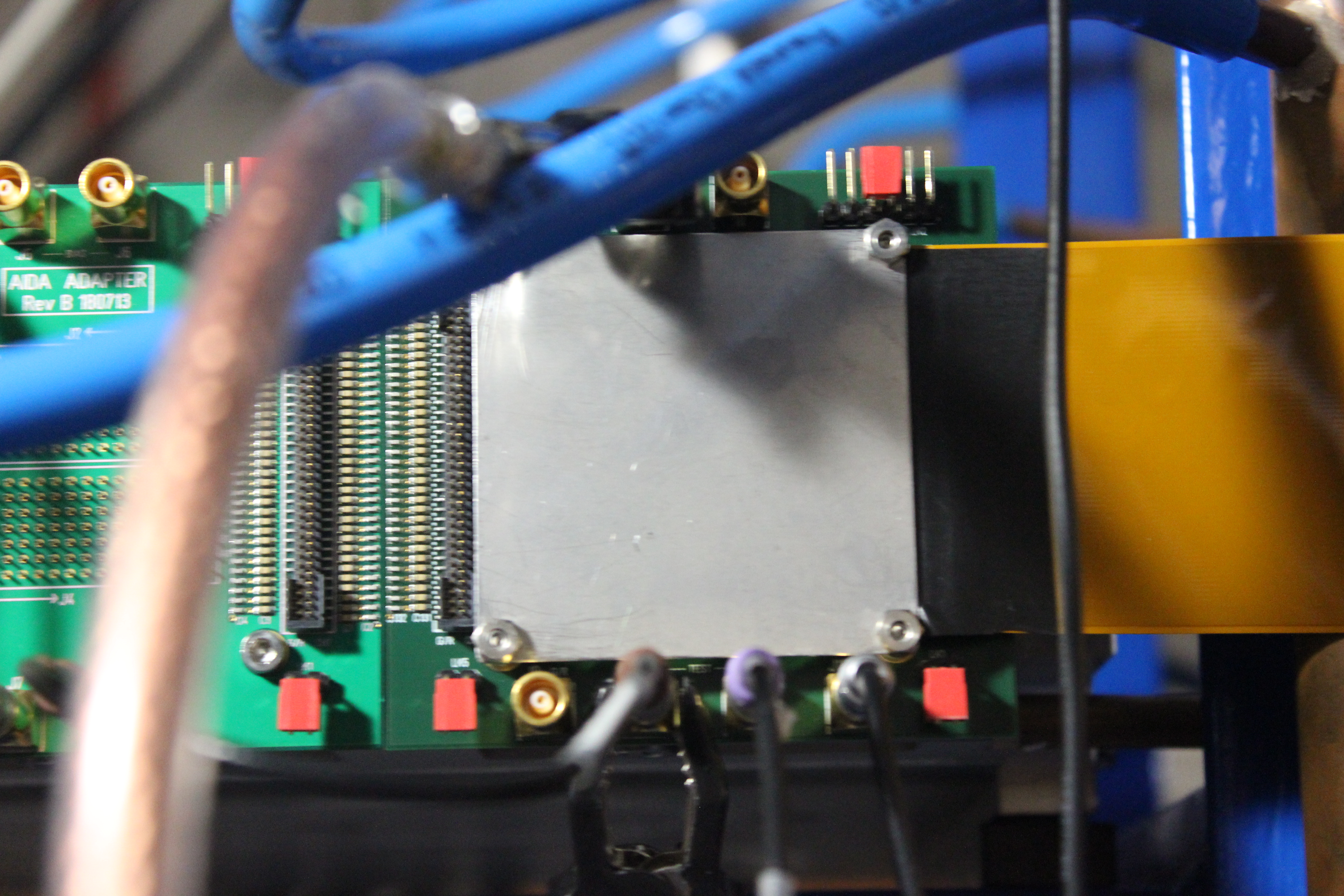
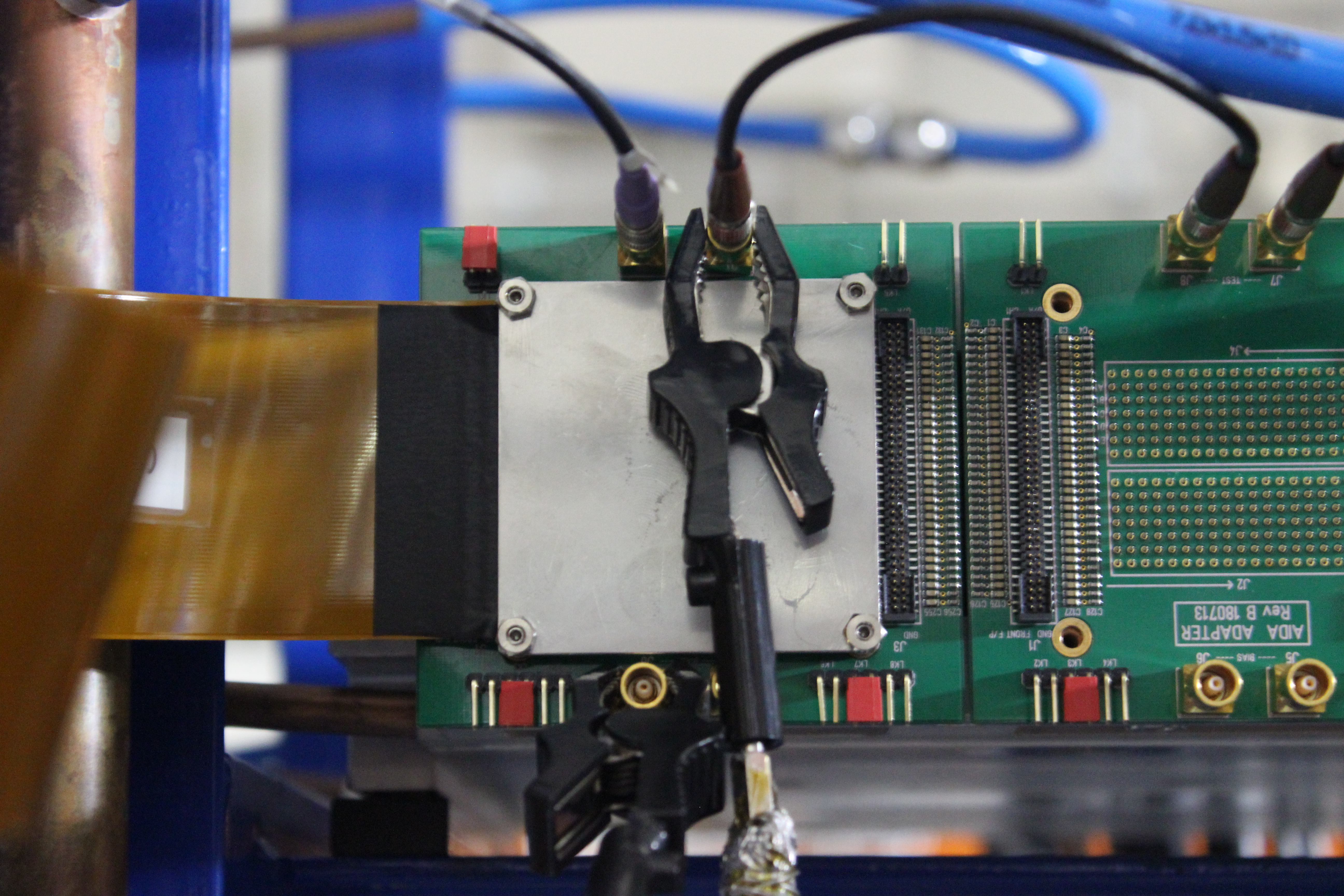
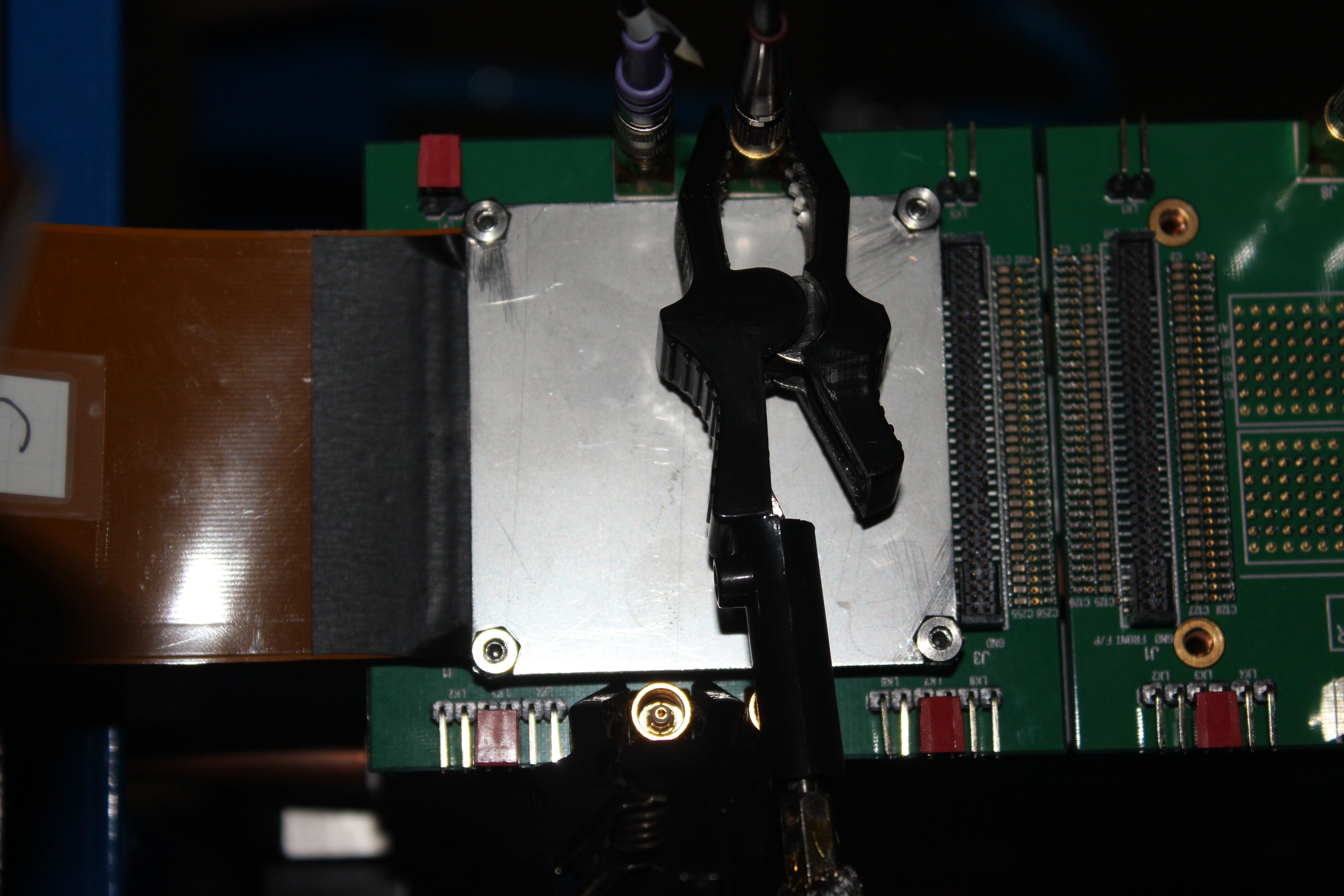
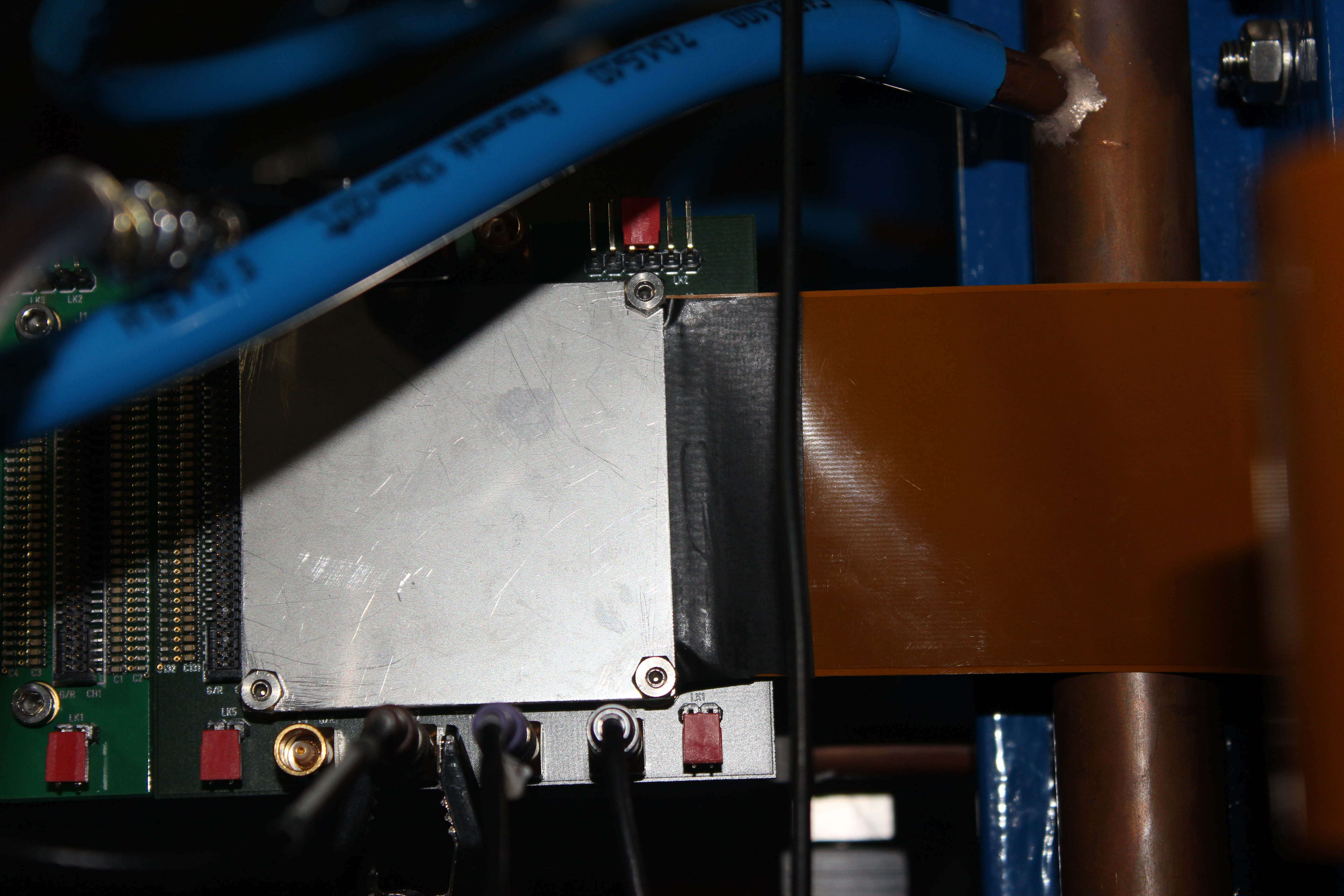
TD | AIDA adaptor PCB configuration - RIKEN - Feb 2015 |
|
| Attachment 1: IMG_2781.JPG
|
|
| Attachment 2: IMG_2782.JPG
|
|
| Attachment 3: IMG_2783.JPG
|
|
| Attachment 4: IMG_2784.JPG
|
|
| Attachment 5: IMG_2787.JPG
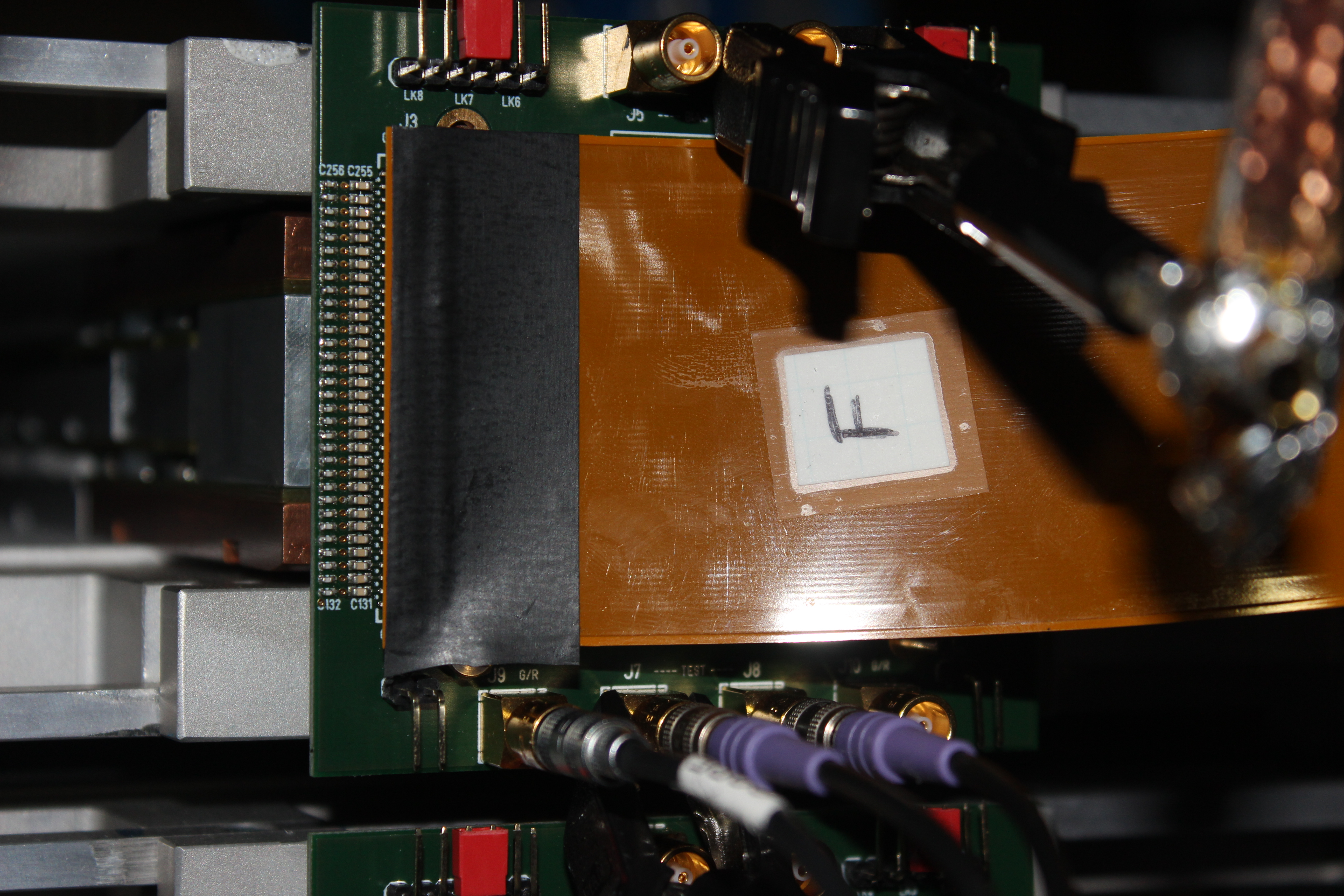
|
|
| Attachment 6: IMG_2796.JPG
|

|
|
56
|
Sat Apr 18 09:30:11 2015 |
CG | To do list 19/04/15 - 21/04/15 |
To do (roughly in order):
- Move shipped boxes down from Gabor's office to the experimental area. Check contents. Should include:
- 3x 3Tb HDD
- NIM floating HV supply
- 2x Si detector boxes, containing MSL type BB18 detectors 3131-9 + 3131-11 and 3058-9 + 3058-25
- flex circuit tester
- misc items including Al plates, grub nuts etc.
- Put everything back into working positions @ F11.
- Put computer table back to normal. Turn on/check aidas1.
- Reconnect power to chiller. Check water levels, fill if needed. Turn on and check for leaks.
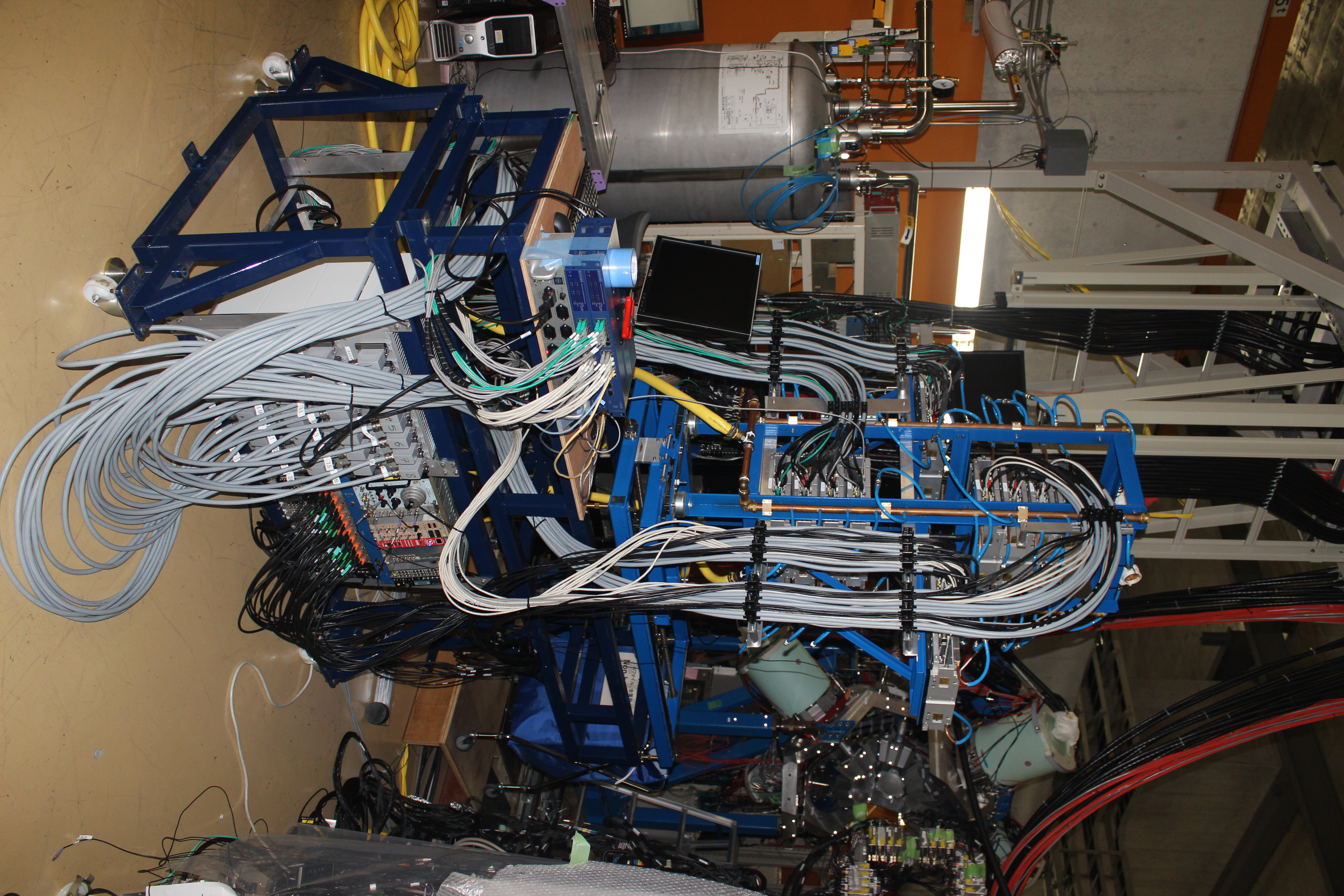
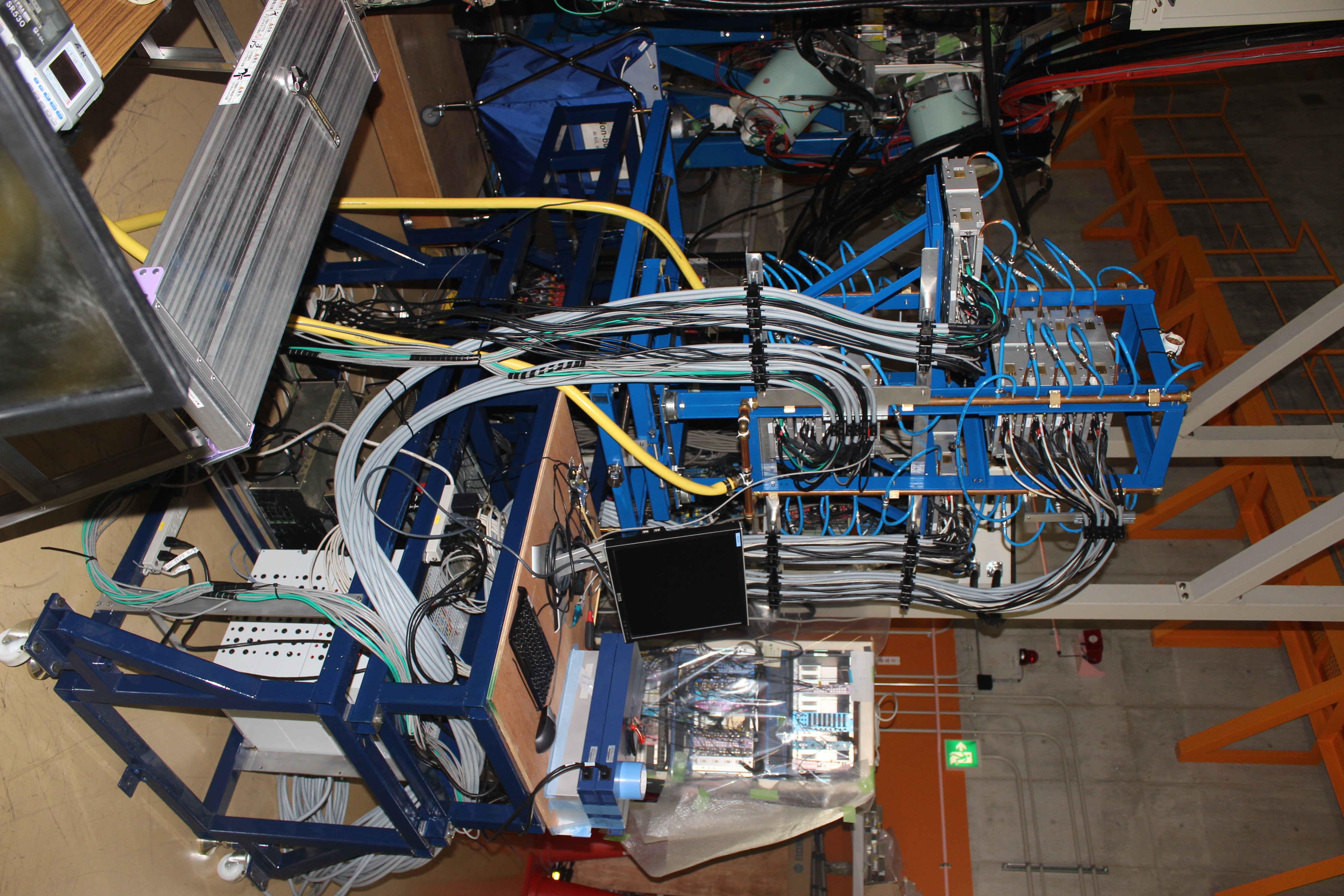
- Install PSUs, USB and network switches in new AIDA base.
- Set up Raspberry Pi.
- Check modified PSU voltages.
- Reconnect FEE64s (power/network/HDMI). Label everything.
- Power on. Check
- Basic pusler test to check function and server. Confirm FWHMs are as expected.
Late Monday or on Tuesday:
- Talk to Shunji re. AIDA/BRIKEN + EURICA setup requirements.
- Install Al/Si accordingly.
- Complete AIDA build with snout, kaptons etc.
- Acquire sources (Am/Bi) for source test ------> Speak to Gabor first thing about this.
|
|
57
|
Mon Apr 20 06:53:24 2015 |
CG, TD | Progress 20th April + RPi procedure |
20/04/15
1200: Complete all points on first part of check list, except checking the PSU voltages.
System now in powered and has all network/HDMI cables attached.
1300: Connect RPi to power switch but when powered on it didn't find the switch. A reliable procedure to start seems to be...
- connect USB power switch to RPI, make sure serial cable is disconnected from hub
- power up RPi and power switch
- check connection using dmesg, should see ...FT232RL for USB power switch on USB0
- check connection from aidas1 by pinging RPi inet address 10.1.1.251
- if good, Rly16 page should work from aidas1
- connect serial cable, open PuTTY session, select AIDA console settings, open
- should assign serial cable as USB1 an allow use of both the power switch and FEE console.
Currently this all works, we can control the power switch both from the RPi and aidas1, and see the FEE console via PuTTY session.
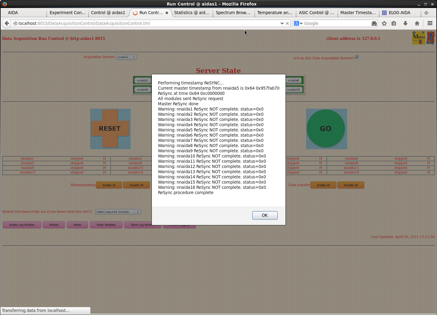
1400: Powered on system and tried to set up DAQ but received error (attachment 1) when doing the initial system reset in Run Control.
DAQ still usable for spectrum/temperature viewing, and all FEEs can be accessed to check ASIC control, but it seems timestamping will not be correct.
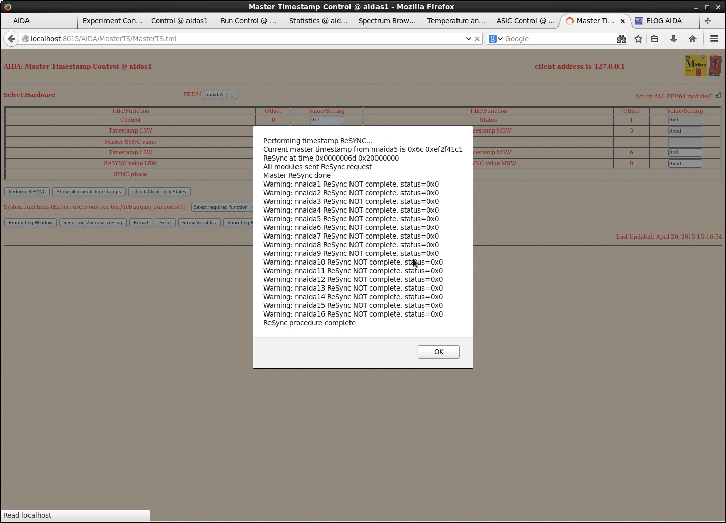
Tried to perform manual ReSync from master timestamp window and received similar error (attachment 2).
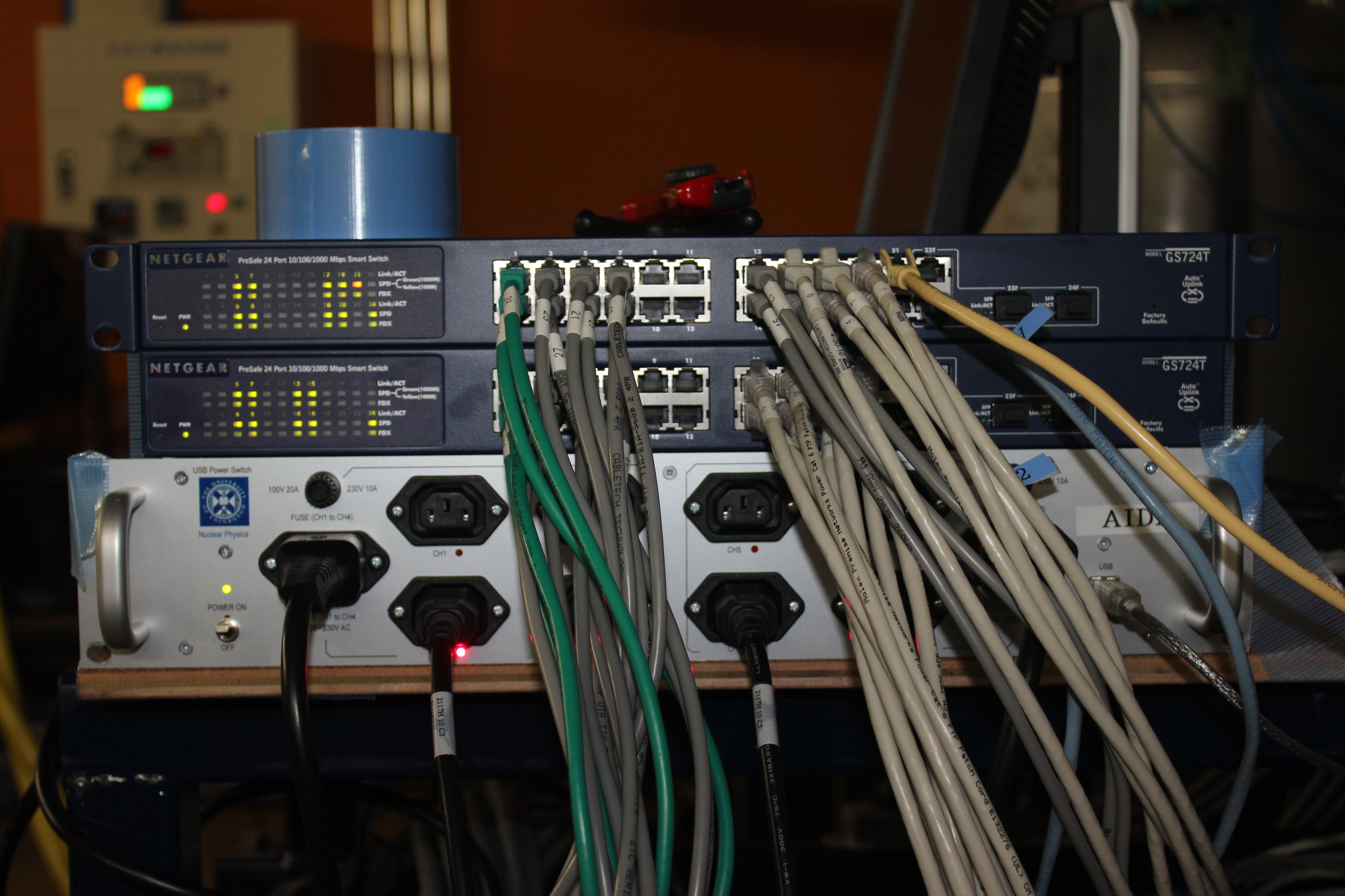
1430: nnaida8 running quite hot (ASIC temp ~65oC) and ASIC temp on nnaida7+15 read as 0.00oC. Otherwise, from pulser/stats data, both seem to be working correctly.
Unplugged power cable for nnaida7+8 at PSU end.
1600: Could timestamping issue originate from MACBs?
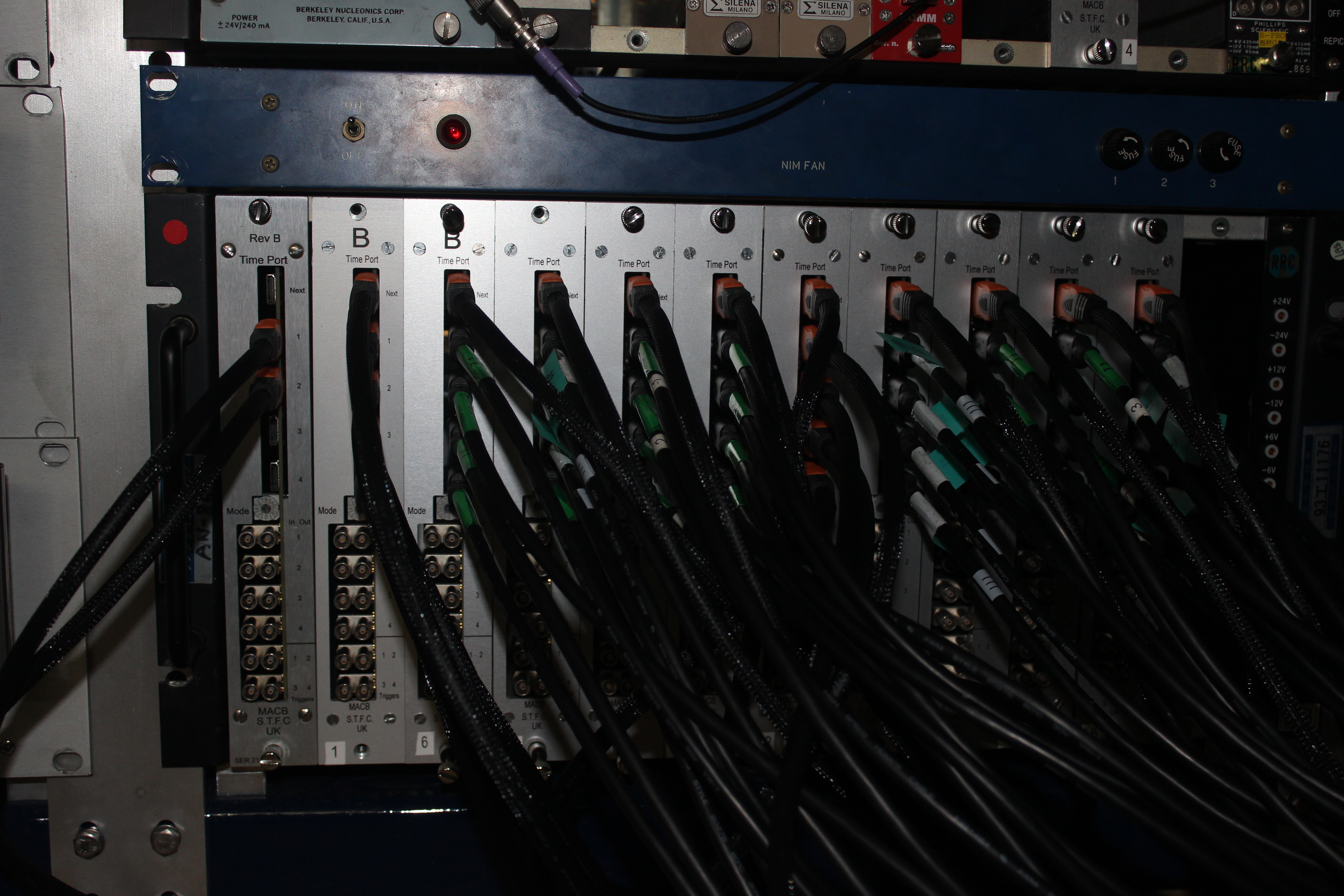
In rebuilding AIDA MACB -> FEE cabling redone. Should it follow a particular pattern/tree?
Current tree structure looks like (with MACB numbering going 1->11 L->R as you look at it):
MACB1(setting: 0) ------- out 1: MACB2 (setting: 2) ---------- out 1: MACB3 (setting: 2) -> nnaida3+4, 11+12
---------- out 2: MACB4 (setting: 3) -> nnaida19+20, 27+28
---------- out 3: MACB5 (setting: 3) -> nniada1+2, 9+10
---------- out 4: MACB6 (setting: 3) -> nnaida17+18, 25+26
--------- out 2: MACB7 (setting: 3) ---------- out 1: MACB8 (setting: 3) -> nnaida21+22, 29+30
---------- out 2: MACB9 (setting: 3) -> nnaida7+8, 15+16
---------- out 3: MACB10 (setting: 3) -> nnaida5+6, 13+14 -----> nnaida5 is the master and this comes from output2.
---------- out 4: MACB11 (setting: 3) -> nnaida23+24, 31+32
Patrick - Is this set up OK? Do certain FEEs need to receive the MACB signal from certain MACBs or just all at the same point in the tree?
Also, MACBs 2+3 are on setting 2 on the dial, whereas the others (except MACB1, the 'grandparent') are set to 3. It seems like a hard thing to change accidentally so are they supposed to be like this or should they all be on the same setting?
1630: Voltages to nnaida7+8 OK at PSU output (+6V, +6V, +6V, -6.5V, +8V). Issue with contact to cooling rack?
With pulser input to all FEEs, only see pulser data in spectra for n-side (nnaida3+4, 7+8, 11+12, 15+16) FEEs. Other FEEs all show zero statistics.
|
| Attachment 1: RunControl_error.png
|
|
| Attachment 2: MasterTSControl_error.png
|
|
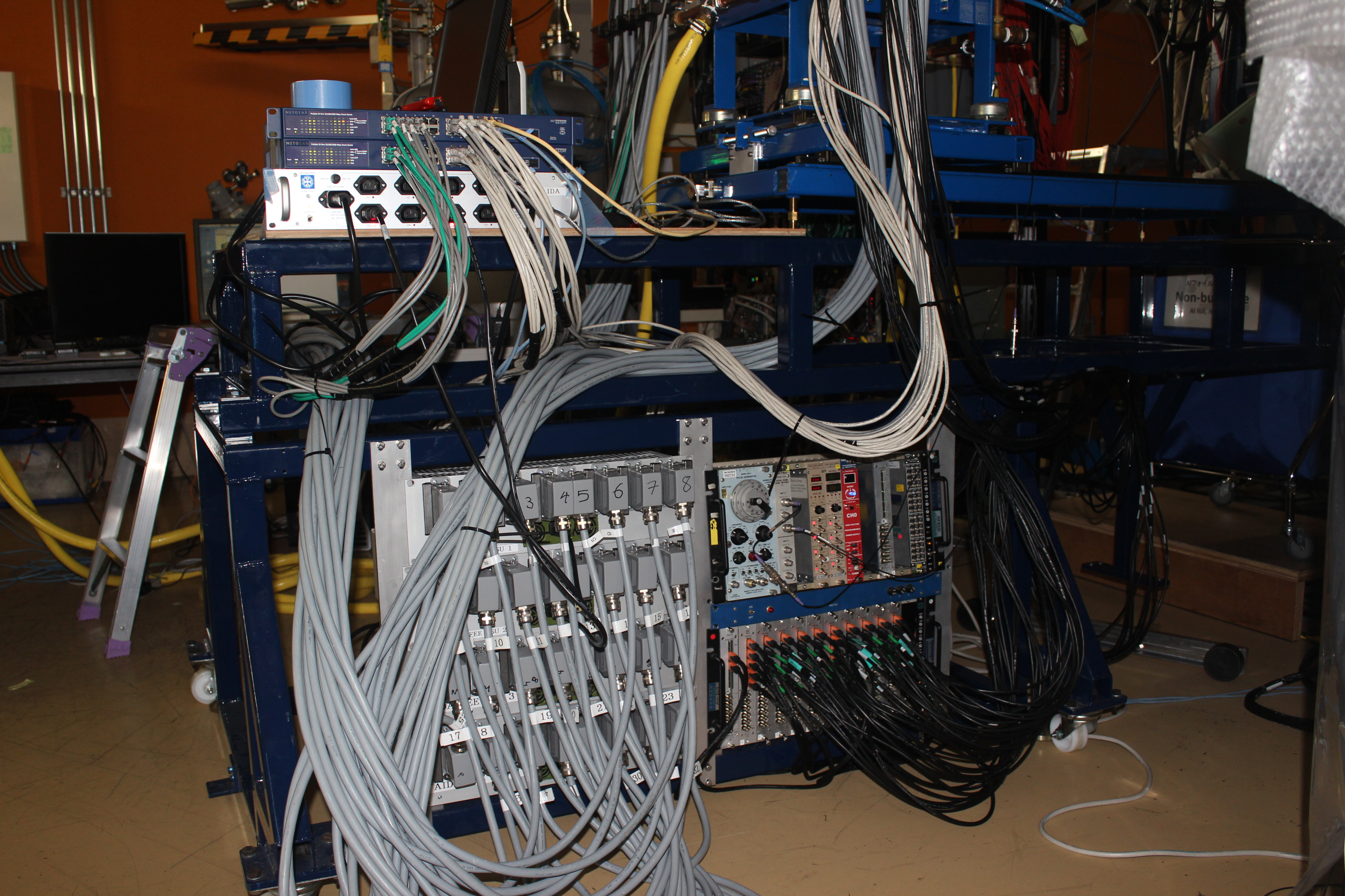
| Attachment 3: IMG_2841.JPG
|
|
| Attachment 4: IMG_2842.JPG
|
|
| Attachment 5: IMG_2843.JPG
|
|
| Attachment 6: IMG_2844.JPG
|
|
| Attachment 7: IMG_2845.JPG
|
|
|
58
|
Mon Apr 20 07:39:49 2015 |
CG, TD | Rasberry Pi : USB ac mains switch + USB serial link to FEE64 console |
It would appear that you cannot reliably startup the Raspberry Pi (nnrpi1)
connected to both the USB ac mains switch *and* the USB-serial link to FEE64
console. This is because the Rly16 Service to the USB ac mains switch expects
to use /dev/ttyUSB0. However this is often assigned (at Raspberry Pi startup)
to the USB-serial link.

You can use the command 'dmesg' to observe device assignments.

Workaround

- connect USB cable from USB ac mains witch to powered USB hub socket
- switch off & disconnect USB-serial cable from powered USB hub socket to FEE64 console
- power up Raspberry Pi (nnrpi1)

At startup the USB ac mains switch should be assigned to the first available
device /dev/ttyUSB0 - as required.

- connect & switch on USB-serial cable from powered USB hub socket to FEE64 console

The USB-serial connection should be assigned to the next available devoce /dev/ttyUSB1
- as required. Further instructions can be found at:

https://elog.ph.ed.ac.uk/AIDA/42 |
|
59
|
Mon Apr 20 09:07:59 2015 |
CG, TD, Patrick Coleman-Smith | Progress 20th April + RPi procedure + reply |
| Quote: |
|
20/04/15
1200: Complete all points on first part of check list, except checking the PSU voltages.
System now in powered and has all network/HDMI cables attached.
1300: Connect RPi to power switch but when powered on it didn't find the switch. A reliable procedure to start seems to be...
- connect USB power switch to RPI, make sure serial cable is disconnected from hub
- power up RPi and power switch
- check connection using dmesg, should see ...FT232RL for USB power switch on USB0
- check connection from aidas1 by pinging RPi inet address 10.1.1.251
- if good, Rly16 page should work from aidas1
- connect serial cable, open PuTTY session, select AIDA console settings, open
- should assign serial cable as USB1 an allow use of both the power switch and FEE console.
Currently this all works, we can control the power switch both from the RPi and aidas1, and see the FEE console via PuTTY session.
1400: Powered on system and tried to set up DAQ but received error (attachment 1) when doing the initial system reset in Run Control.
DAQ still usable for spectrum/temperature viewing, and all FEEs can be accessed to check ASIC control, but it seems timestamping will not be correct.
Tried to perform manual ReSync from master timestamp window and received similar error (attachment 2).
1430: nnaida8 running quite hot (ASIC temp ~65oC) and ASIC temp on nnaida7+15 read as 0.00oC. Otherwise, from pulser/stats data, both seem to be working correctly.
Unplugged power cable for nnaida7+8 at PSU end.
1600: Could timestamping issue originate from MACBs?
In rebuilding AIDA MACB -> FEE cabling redone. Should it follow a particular pattern/tree?
Current tree structure looks like (with MACB numbering going 1->11 L->R as you look at it):
MACB1(setting: 0) ------- out 1: MACB2 (setting: 2) ---------- out 1: MACB3 (setting: 2) -> nnaida3+4, 11+12
---------- out 2: MACB4 (setting: 3) -> nnaida19+20, 27+28
---------- out 3: MACB5 (setting: 3) -> nniada1+2, 9+10
---------- out 4: MACB6 (setting: 3) -> nnaida17+18, 25+26
--------- out 2: MACB7 (setting: 3) ---------- out 1: MACB8 (setting: 3) -> nnaida21+22, 29+30
---------- out 2: MACB9 (setting: 3) -> nnaida7+8, 15+16
---------- out 3: MACB10 (setting: 3) -> nnaida5+6, 13+14 -----> nnaida5 is the master and this comes from output2.
---------- out 4: MACB11 (setting: 3) -> nnaida23+24, 31+32
Patrick - Is this set up OK? Do certain FEEs need to receive the MACB signal from certain MACBs or just all at the same point in the tree?
Also, MACBs 2+3 are on setting 2 on the dial, whereas the others (except MACB1, the 'grandparent') are set to 3. It seems like a hard thing to change accidentally so are they supposed to be like this or should they all be on the same setting?
1630: Voltages to nnaida7+8 OK at PSU output (+6V, +6V, +6V, -6.5V, +8V). Issue with contact to cooling rack?
With pulser input to all FEEs, only see pulser data in spectra for n-side (nnaida3+4, 7+8, 11+12, 15+16) FEEs. Other FEEs all show zero statistics.
|
The MACB system of clock and SYNC pulse distribution does have to follow some rules.
The Master needs to be in a very particular place. The rest are less important as long as they are all at the same level in the tree.
In the tree you report above and using the numbering you report. The Master should be in MACB3:out1.
The settings you have shown are correct if the Master is placed correctly ...
I will input a separate Elog entry detailing the settings for the MACB and the rules for the tree.
Regarding nnaida7+8. I agree the issue to tackle first is the cooling plate contact to the module. Where do they feature in the layout ?
Is the plate tightened up correctly ?
Regarding the P side FEE64s ... sorry about this ... but is the P pulser working ... well i did have to ask ;-)
|
|
60
|
Mon Apr 20 09:38:15 2015 |
CG, TD, Patrick Coleman-Smith | Progress 20th April + RPi procedure + reply |
| Quote: |
|
| Quote: |
|
20/04/15
1200: Complete all points on first part of check list, except checking the PSU voltages.
System now in powered and has all network/HDMI cables attached.
1300: Connect RPi to power switch but when powered on it didn't find the switch. A reliable procedure to start seems to be...
- connect USB power switch to RPI, make sure serial cable is disconnected from hub
- power up RPi and power switch
- check connection using dmesg, should see ...FT232RL for USB power switch on USB0
- check connection from aidas1 by pinging RPi inet address 10.1.1.251
- if good, Rly16 page should work from aidas1
- connect serial cable, open PuTTY session, select AIDA console settings, open
- should assign serial cable as USB1 an allow use of both the power switch and FEE console.
Currently this all works, we can control the power switch both from the RPi and aidas1, and see the FEE console via PuTTY session.
1400: Powered on system and tried to set up DAQ but received error (attachment 1) when doing the initial system reset in Run Control.
DAQ still usable for spectrum/temperature viewing, and all FEEs can be accessed to check ASIC control, but it seems timestamping will not be correct.
Tried to perform manual ReSync from master timestamp window and received similar error (attachment 2).
1430: nnaida8 running quite hot (ASIC temp ~65oC) and ASIC temp on nnaida7+15 read as 0.00oC. Otherwise, from pulser/stats data, both seem to be working correctly.
Unplugged power cable for nnaida7+8 at PSU end.
1600: Could timestamping issue originate from MACBs?
In rebuilding AIDA MACB - > FEE cabling redone. Should it follow a particular pattern/tree?
Current tree structure looks like (with MACB numbering going 1->11 L->R as you look at it):
MACB1 (setting: 0) ------- out 1: MACB2 (setting: 2) ---------- out 1: MACB3 (setting: 2) -> nnaida3+4, 11+12
&nb sp; &nb sp; ---------- out 2: MACB4 (setting: 3) -> nnaida19+20, 27+28
&nb sp; &nb sp; ---------- out 3: MACB5 (setting: 3) -> nniada1+2, 9+10
&nb sp; &nb sp; ---------- out 4: MACB6 (setting: 3) -> nnaida17+18, 25+26
&nb sp; --------- out 2: MACB7 (setting: 3) ---------- out 1: MACB8 (setting: 3) -> nnaida21+22, 29+30
&nb sp; &nb sp; ---------- out 2: MACB9 (setting: 3) -> nnaida7+8, 15+16
&nb sp; &nb sp; ---------- out 3: MACB10 (setting: 3) -> nnaida5+6, 13+14 -----> nnaida5 is the master and this comes from output2.
&nb sp; &nb sp; ---------- out 4: MACB11 (setting: 3) -> nnaida23+24, 31+32
Patrick - Is this set up OK? Do certain FEEs need to receive the MACB signal from certain MACBs or just all at the same point in the tree?
Also, MACBs 2+3 are on setting 2 on the dial, whereas the others (except MACB1, the 'grandparent') are set to 3. It seems like a hard thing to change accidentally so are they supposed to be like this or should they all be on the same setting?
1630: Voltages to nnaida7+8 OK at PSU output (+6V, +6V, +6V, -6.5V, +8V). Issue with contact to cooling rack?
With pulser input to all FEEs, only see pulser data in spectra for n-side (nnaida3+4, 7+8, 11+12, 15+16) FEEs. Other FEEs all show zero statistics.
|
The MACB system of clock and SYNC pulse distribution does have to follow some rules.
The Master needs to be in a very particular place. The rest are less important as long as they are all at the same level in the tree.
In the tree you report above and using the numbering you report. The Master should be in MACB3:out1.
The settings you have shown are correct if the Master is placed correctly ...
I will input a separate Elog entry detailing the settings for the MACB and the rules for the tree.
Thanks
Regarding nnaida7+8. I agree the issue to tackle first is the cooling plate contact to the module. Where do they feature in the layout ?
Is the plate tightened up correctly ?
As far as I am aware this module/crate has not recently been opened so the 'contact' should be as good (or bad) as it ever was.
But it would, of course, bear checking.
Regarding the P side FEE64s ... sorry about this ... but is the P pulser working ... well i did have to ask ;-
According to a DSO the positive and negative pulser inputs and cabling are OK
|
|