| ID |
Date |
Author |
Subject |
|
20
|
Wed Dec 3 12:13:03 2014 |
Alfredo Estrade | IV curve with CAEN N1419 |
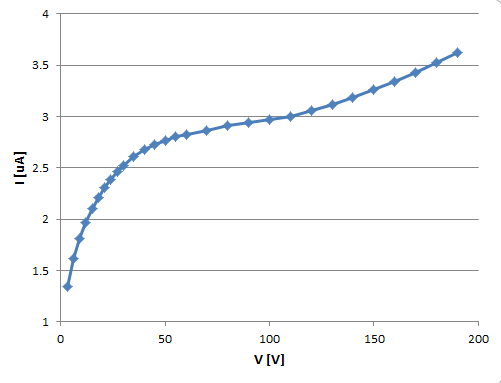
Measured IV curve for BB18 DSSD with new CAEN HV supply. Settings as in previous elog entry:

Detector bias CAEN N1419 Programmable HV Power Supply
  - FAGND isolated from AGND (AGND = NIM chassis ground)
  - floating HV supply, <5mV pp noise specification
  - configured + polarity, i.e. core to nnaida11 & nnaida12 MSL type BB18 n+n ohmic strips
                                braid to nnaida12 & nnaida13 MSL type BB18 p+n junction strips


Data (see attachment):
V [V]	I [uA]
3	1.34
6	1.62
9	1.81
12	1.97
15	2.1
18	2.21
21	2.31
24	2.39
27	2.46
30	2.52
35	2.61
40	2.68
45	2.73
50	2.77
55	2.8
60	2.82
70	2.86
80	2.91
90	2.94
100	2.97
110	3
120	3.06
130	3.12
140	3.18
150	3.26
160	3.34
170	3.43
180	3.53
190 3.62 |
| Attachment 1: IV_dec14.PNG
|
|
|
19
|
Thu Nov 20 14:05:21 2014 |
Tom Davinson | AIDA Tests at STFC DL - PCS, TD |
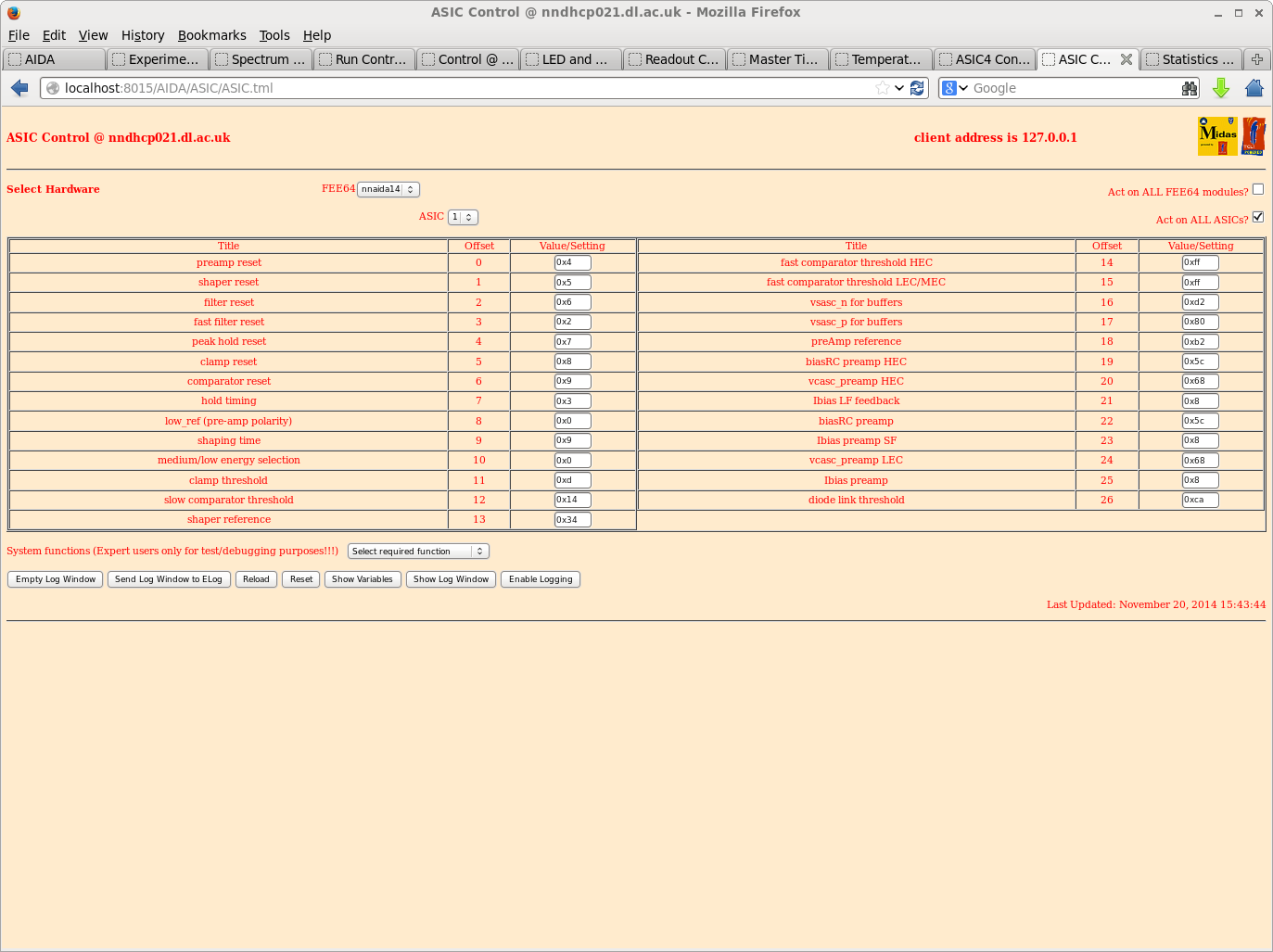
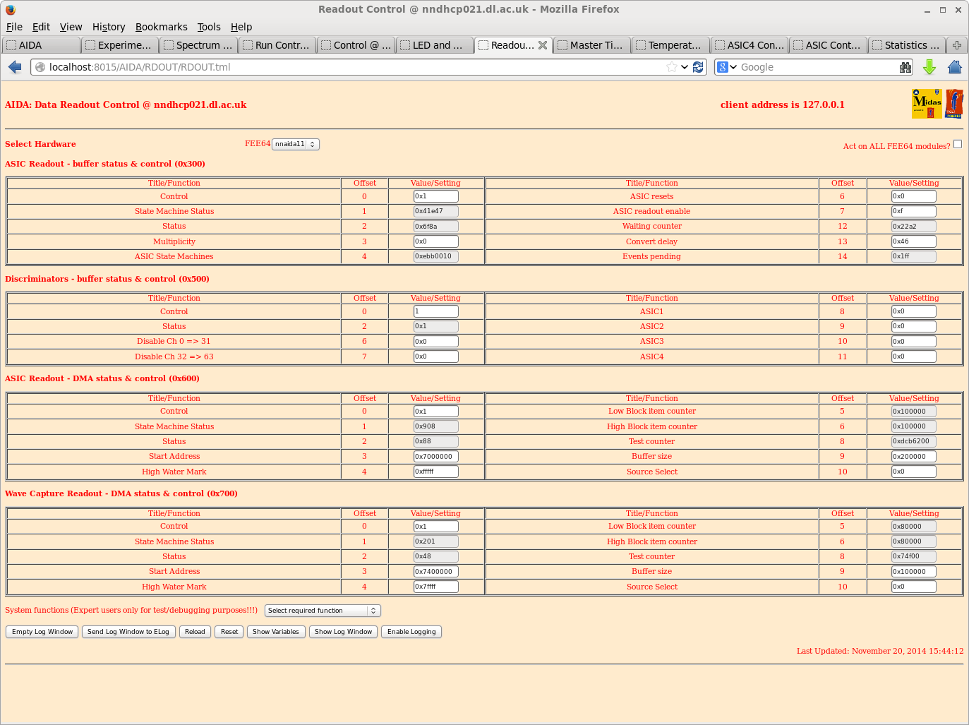
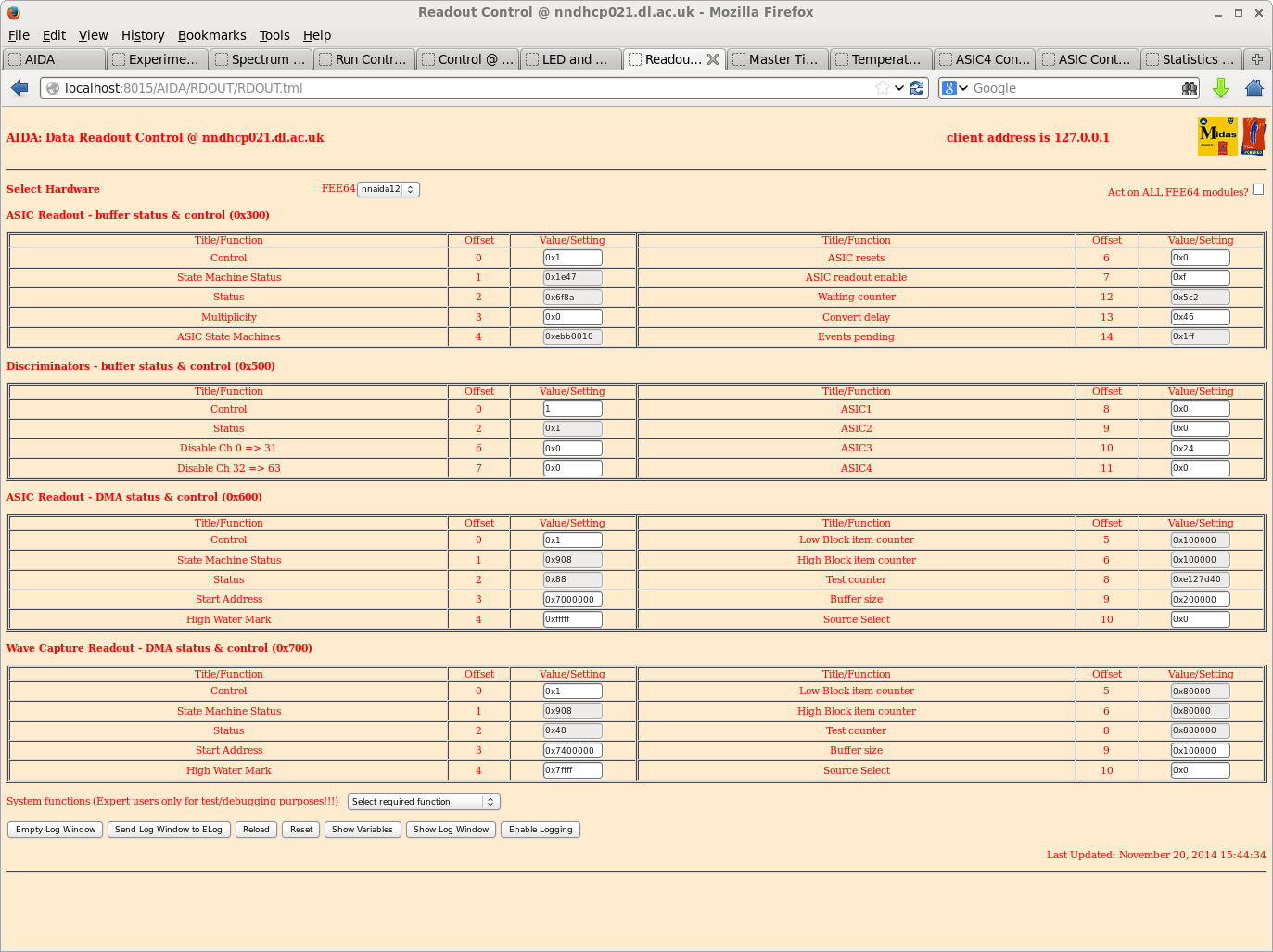
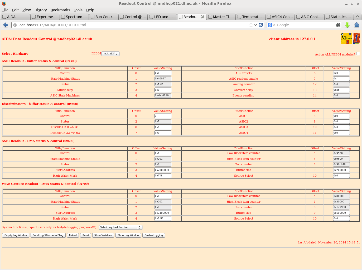
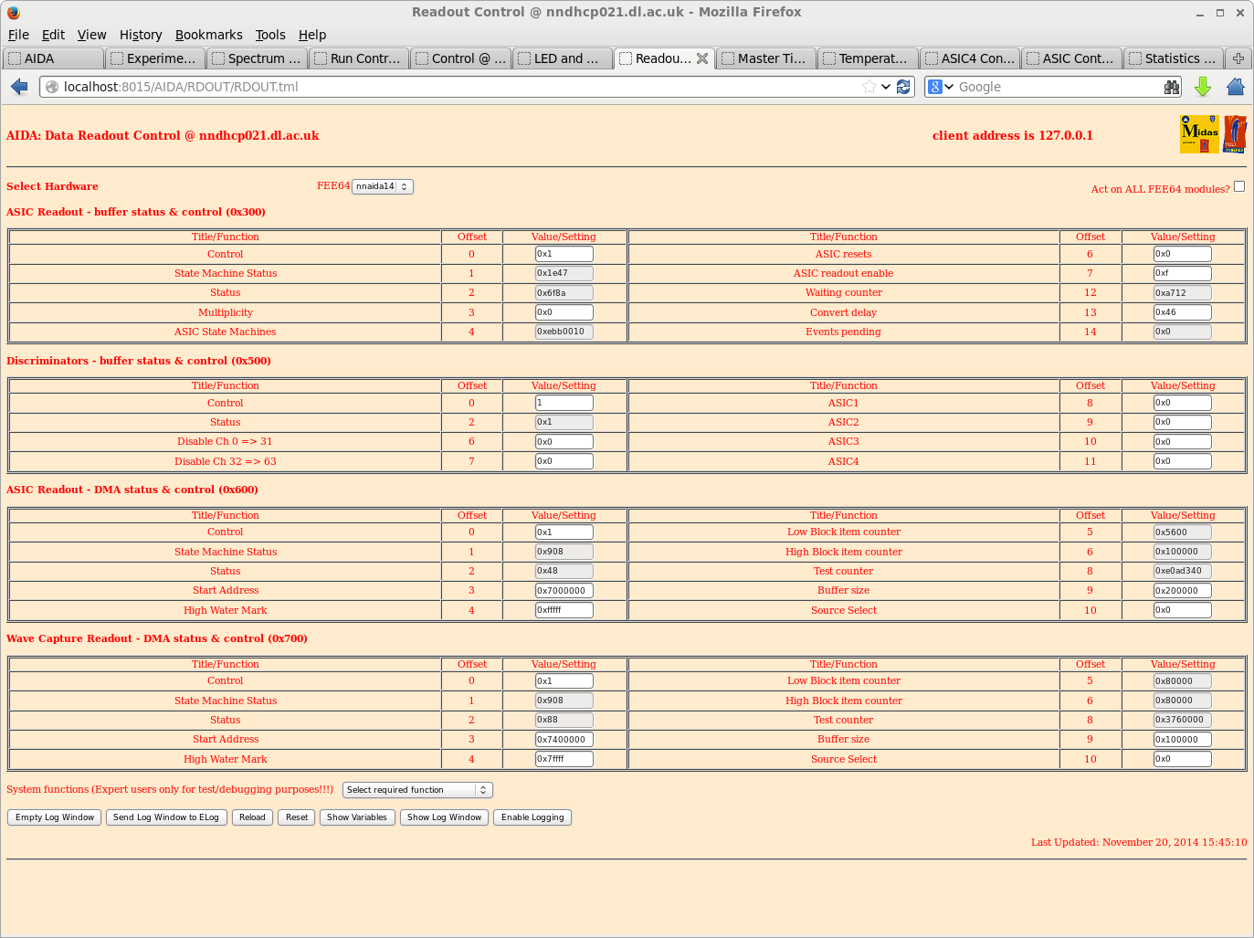
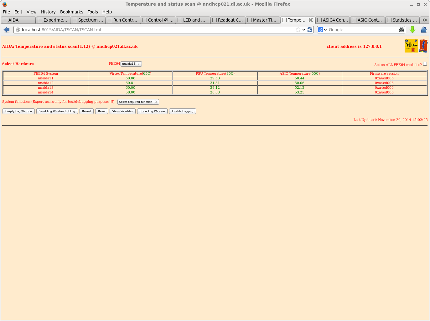
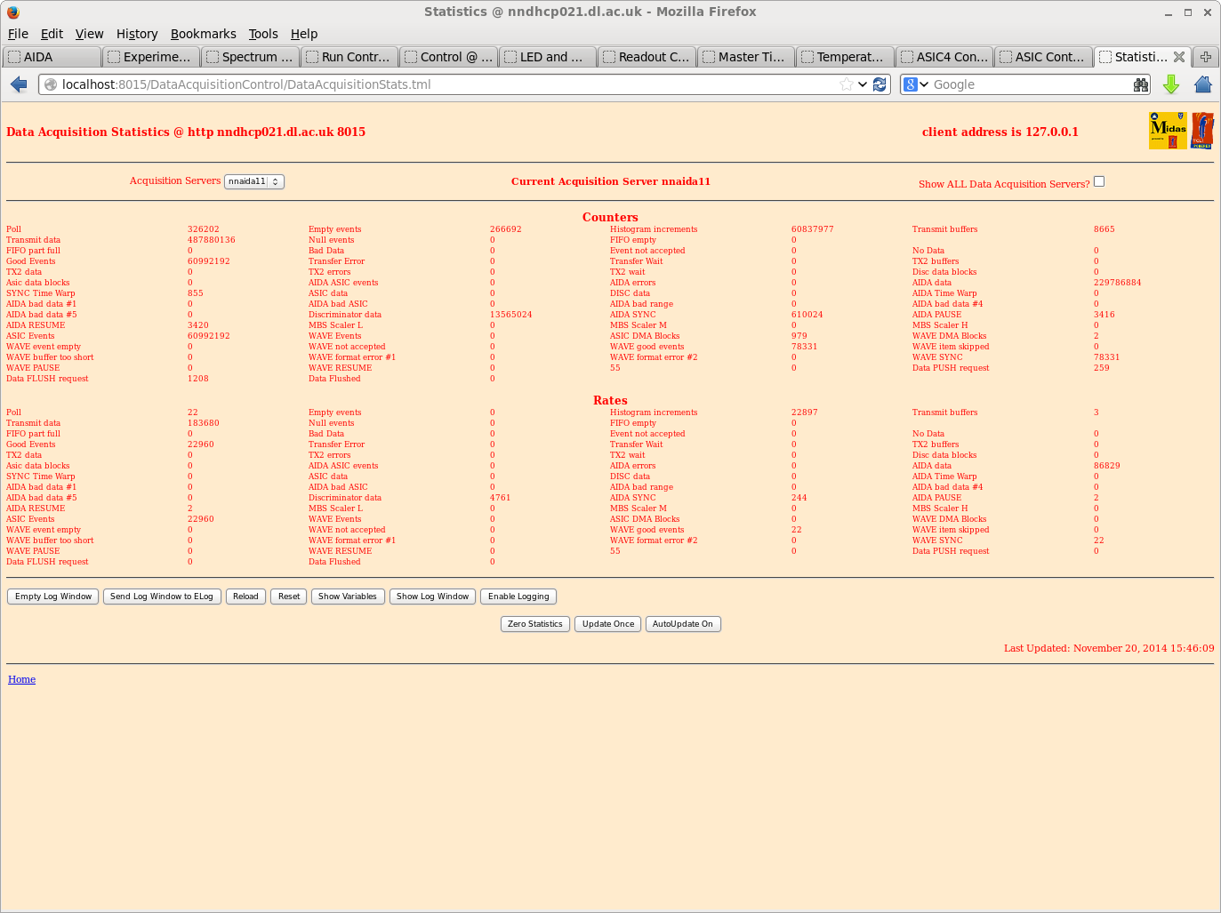
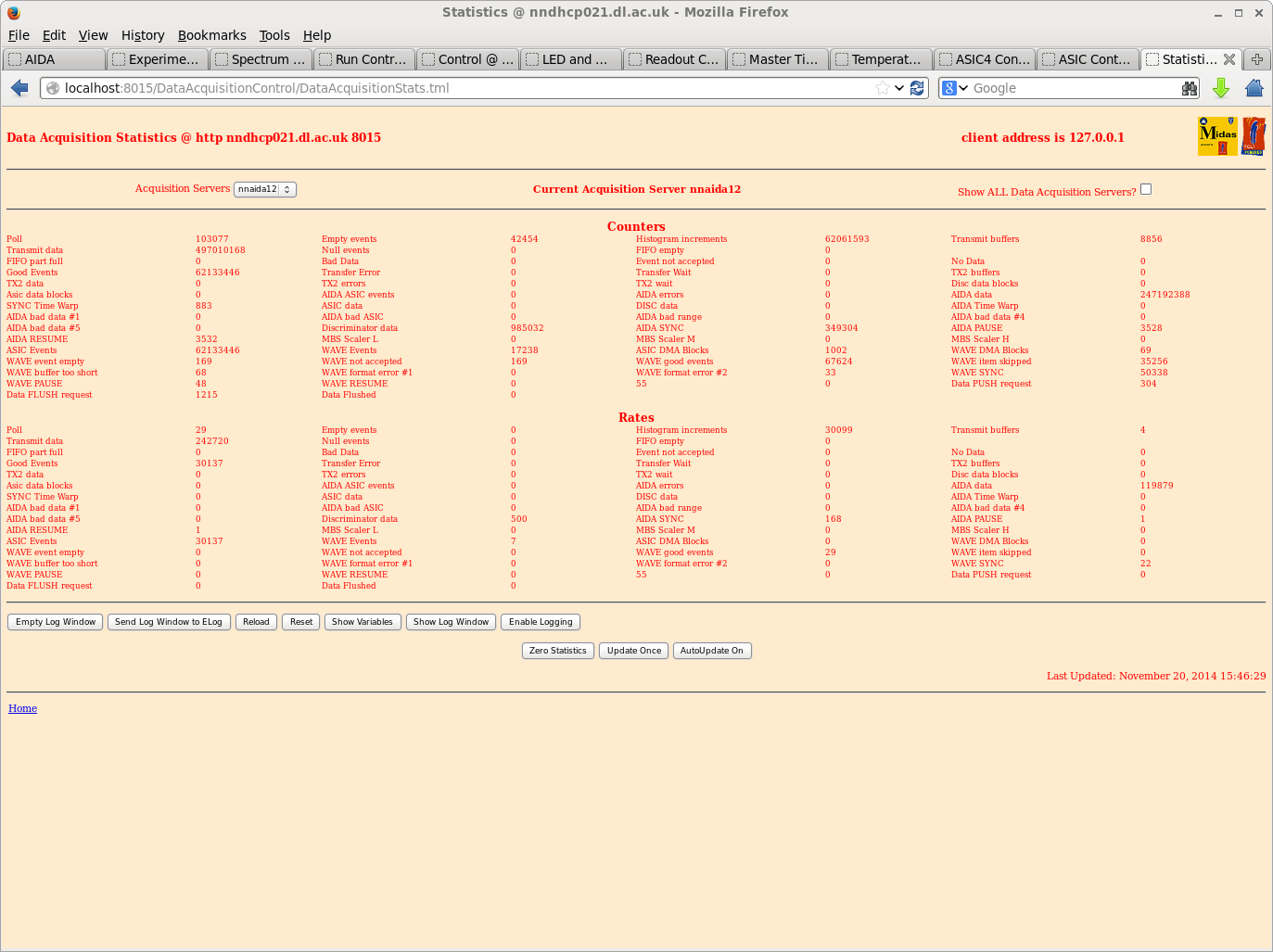
Configuration per Elog entries:

https://elog.ph.ed.ac.uk/AIDA/3
https://elog.ph.ed.ac.uk/AIDA/4

- except -

FEE firmware
  - reverted release 0xa4ed006
    as used at RIKEN due to stability/data issues with most recent releases

Detector bias CAEN N1419 Programmable HV Power Supply
  - FAGND isolated from AGND (AGND = NIM chassis ground)
  - floating HV supply, <5mV pp noise specification
  - configured + polarity, i.e. core to nnaida11 & nnaida12 MSL type BB18 n+n ohmic strips
                                braid to nnaida12 & nnaida13 MSL type BB18 p+n junction strips
  - configured bias voltage to 200V, max bias voltage 200V, max leakage current 20uA,
    trip 10s, ramp up/down 1V/s
  - bias 200V, leakage current 4.9-5.1uA

ASIC parameters

  Default ASIC parameters (EXPERIMENT/AIDA/2014Aug13-13.44.58) except
  - shaping time 5us
  - slow comparator 20 (hex 14)

R31

  - 207Bi source (serial AD6201) mounted c. 3cm from MSL type BB18 DSSSD
  - p+n junction side faces 207Bi source
  - source serial number *away* from DSSSD

  - Pulser BNC PB-5
    fall time 1ms
    rate 10Hz
    delay 250ns
    ampl 1.00000V
    polarity -
    pulse top tail
    atten x1

    positive polarity test input via EG&G Ortec 433A

R32

  - 207Bi source (serial AD6201) mounted c. 3cm from MSL type BB18 DSSSD
  - p+n junction side faces 207Bi source
  - source serial number faces DSSSD

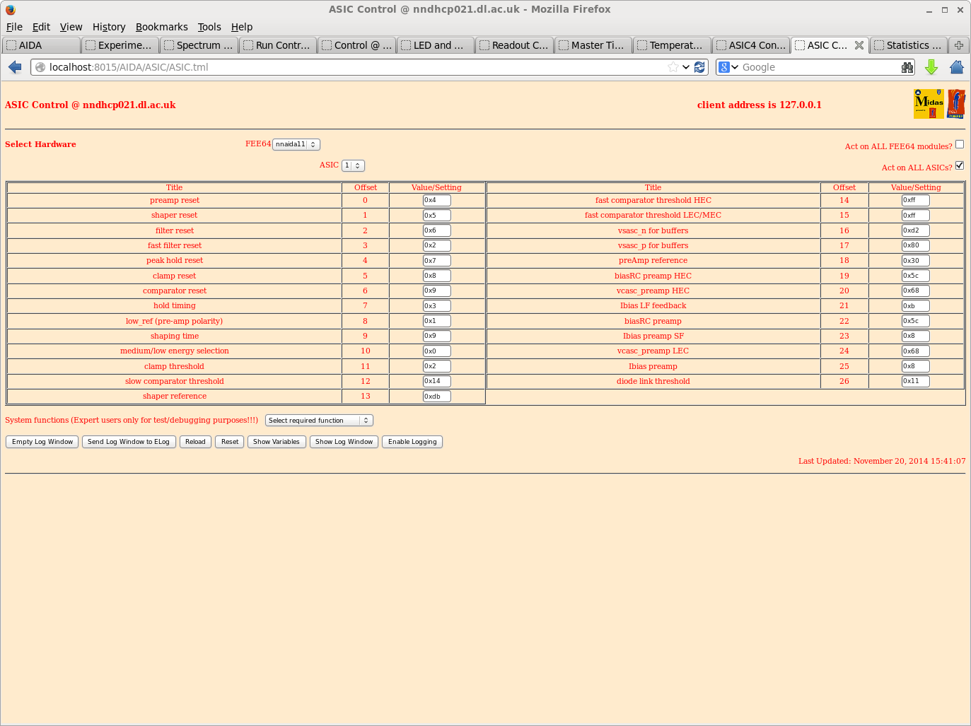
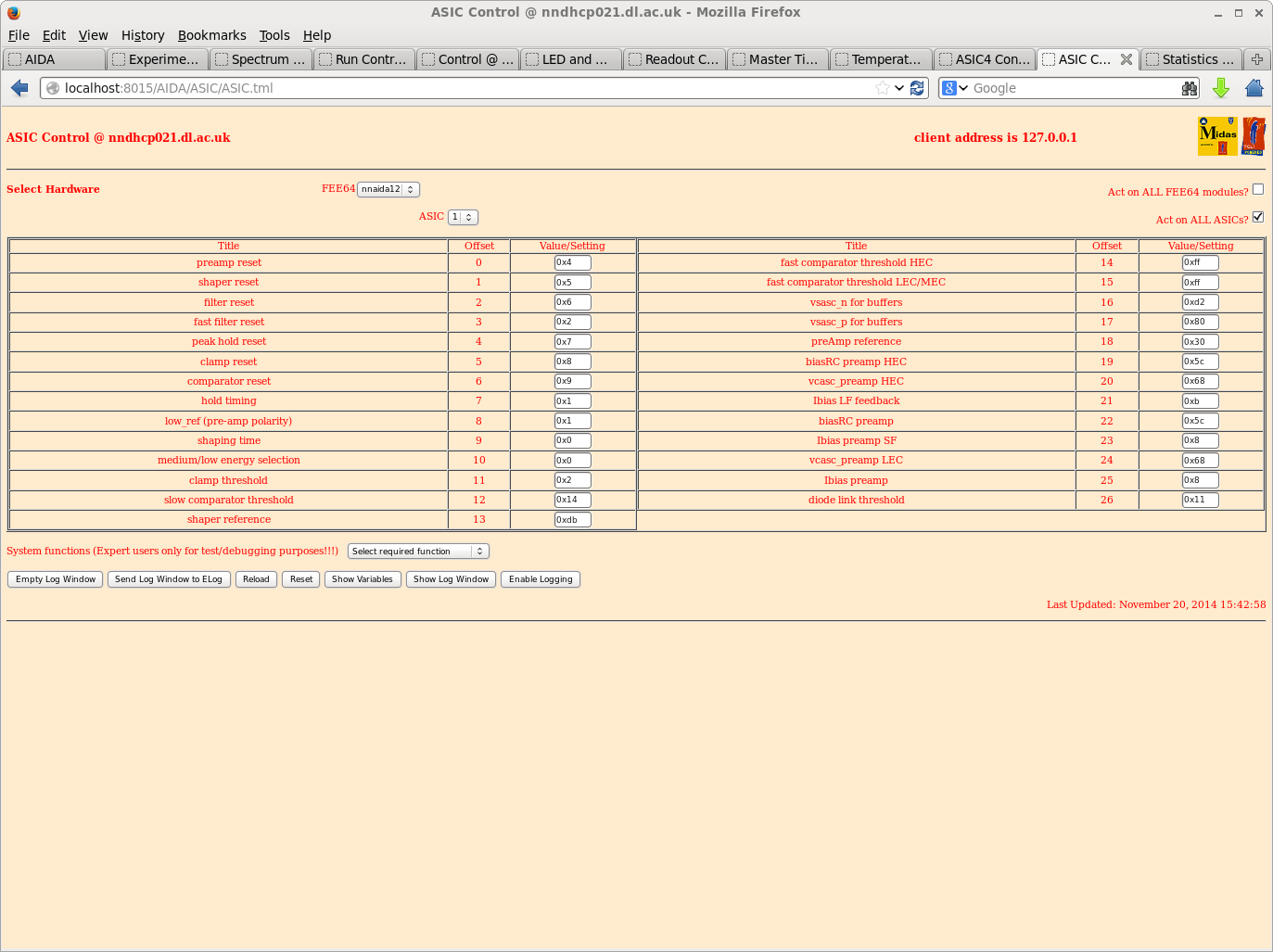
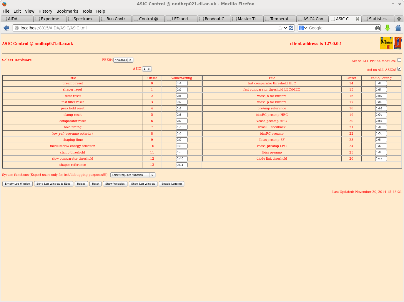
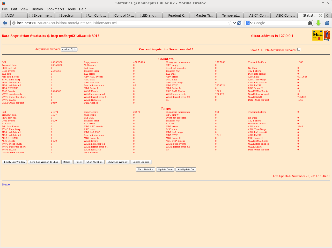
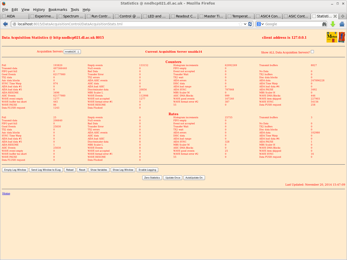
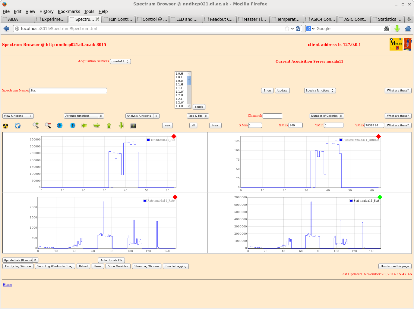
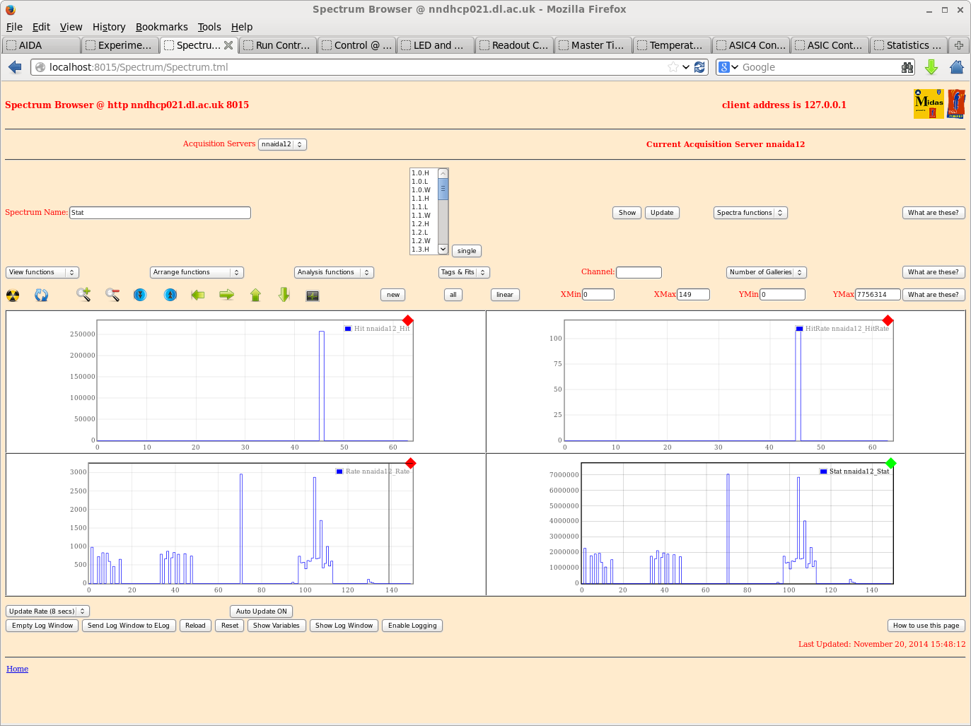
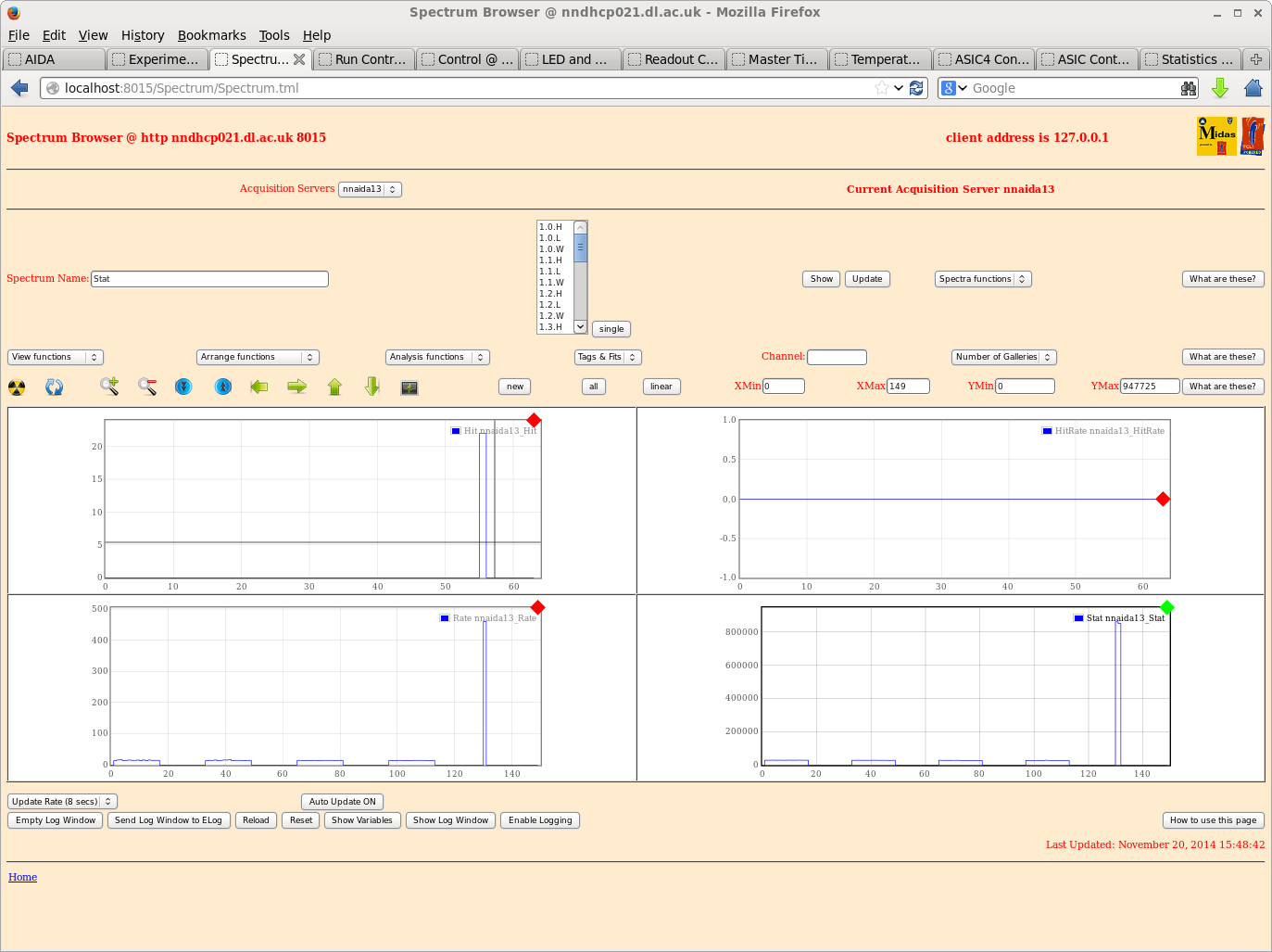
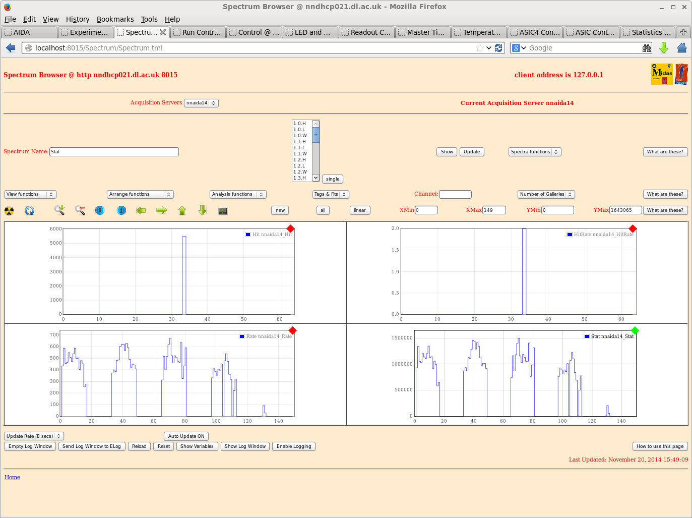
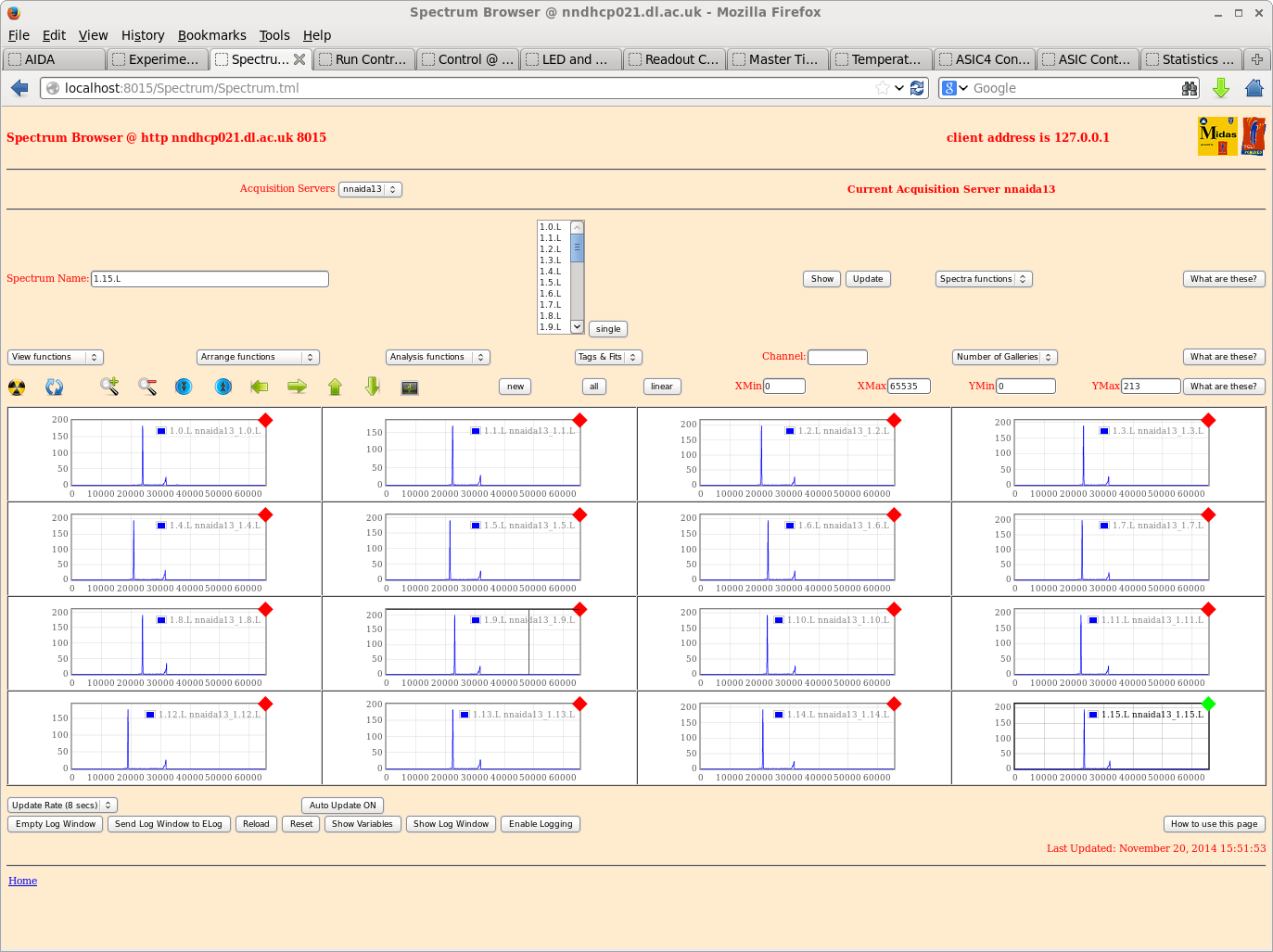
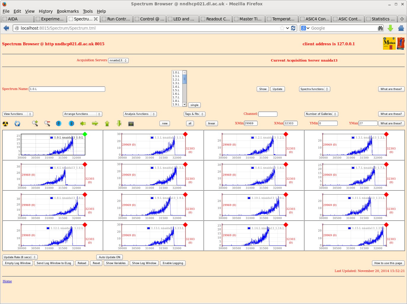
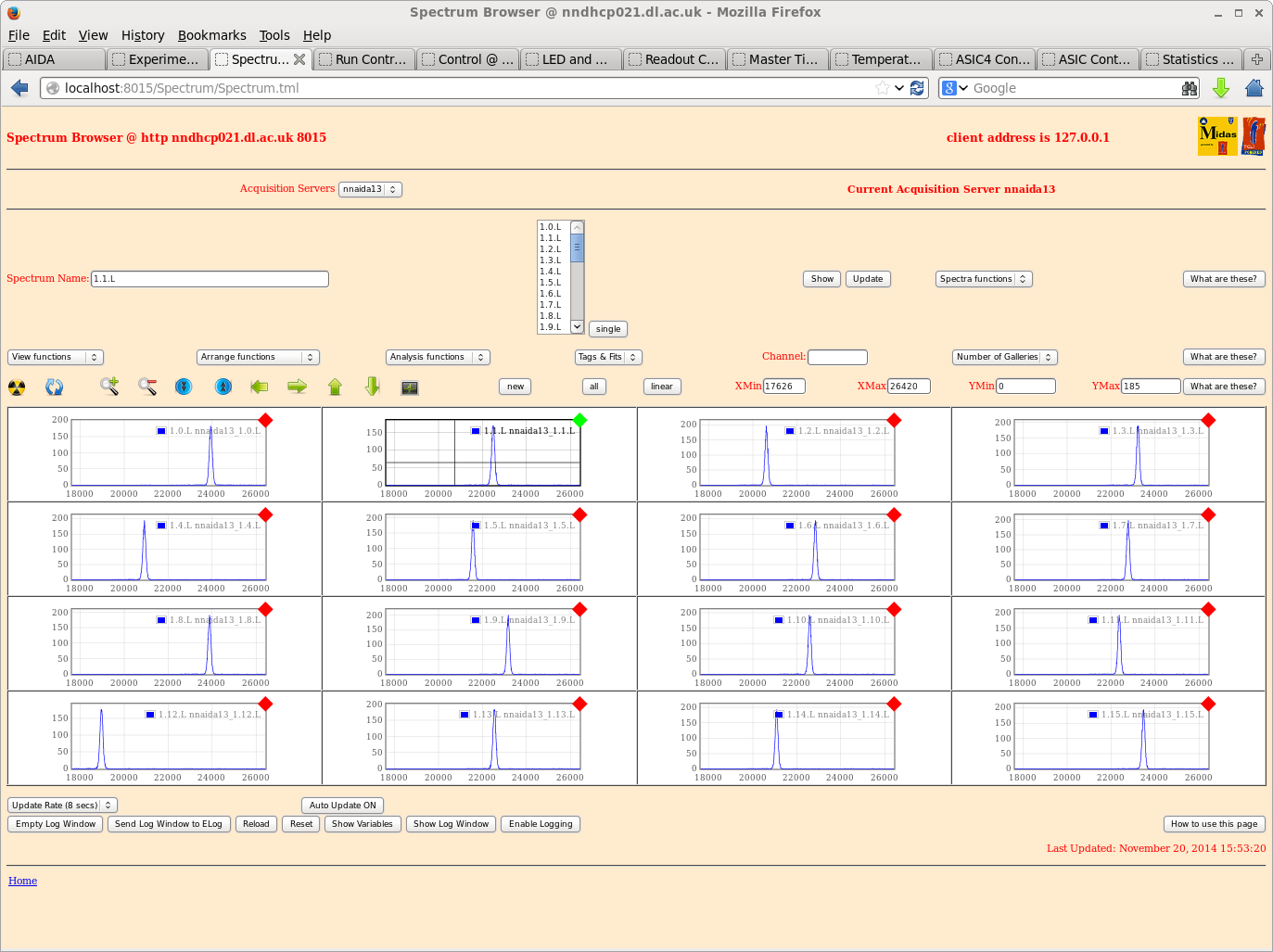
Attachments 1-20 from R32 |
| Attachment 1: 1.png
|
|
| Attachment 2: 2.png
|
|
| Attachment 3: 3.png
|
|
| Attachment 4: 4.png
|
|
| Attachment 5: 5.png
|
|
| Attachment 6: 6.png
|
|
| Attachment 7: 7.png
|
|
| Attachment 8: 8.png
|
|
| Attachment 9: 9.png
|
|
| Attachment 10: 10.png
|
|
| Attachment 11: 11.png
|
|
| Attachment 12: 12.png
|
|
| Attachment 13: 13.png
|
|
| Attachment 14: 14.png
|
|
| Attachment 15: 15.png
|
|
| Attachment 16: 16.png
|
|
| Attachment 17: 17.png
|
|
| Attachment 18: 18.png
|
|
| Attachment 19: 19.png
|
|
| Attachment 20: 20.png
|
|
|
18
|
Fri Oct 24 16:02:26 2014 |
Alfredo Estrade | bench tests with pulser |
Performed pulser measurements with test setup at Daresbury lab, with main purpose of remembering how to operate the system! The status is similar to what Chris observed in Elog entry #14. Confirmed ASIC settings as in entry#4 of elog.
The pulser spectra shows FWHM of ~ 13.5 ch for all FEE64 cards with no DSSD connected to the system (i.e. Kapton cables unplugged). Some channels in a few FEE64 cards show two peaks on the pulse spectra, but still narrow and only slightly wider distribution for the two peak combined (~ 15 ch, see Figure 1).
With the DSSD connected, the pulser spectra shows a double peak structure with FWHM ~ 250 ch for each peak (Figure 2).
However, for NNAIDA#11 and #12 a few ASICs had high level of noise, and were therefore used in the 1GeV range to become quiet (ASIC3 for nnaida#11, ASIC1 and 2 for nnaida#12). Figure 3 and 4 show sample of these noisy channels.
A good question brought up by Patrick is if the true noise level with a biased DSSD corresponds to these 'noisy' ASICs, or to the ones that are much more quiet (maybe some signal path disconnected for these?). Measurements with a radioactive source could clarify this.
Figure 1: pulser, no DSSD connected
Figure 2: double peak structure for pulser spectra for NNAIDA13 (similar spectra seen in the other FEE64 cards)
Figure 3: spectra for NNAIDA#11 with biased DSSD connected, and no pulser signal going into the system (only noise)
Figure 4: spectra for NNAIDA#12 with biased DSSD connected, and no pulser signal going into the system (only noise)
|
|
17
|
Fri Oct 24 15:05:28 2014 |
Patrick and Alfredo | new VHDL: FEE_Riken_Apr14_21.bin |
New VHDL loaded in NNAIDA#11,#12,#13,#14: /MIDAS/Aida/FEE_Riken_Apr14_21.bin
The code introduces the feature of turning ON or OFF individual ASICs in a FEE64 card. This is achieved by turning off the clock signal to a individual ASIC, which then will not produce any data.
Feature controled through "ASIC readout bugger and control", by register onn base address 0x300 and offset 7 (until now 'ASIC readout enable').
Only basic tests of new VHDL were done, but the system seems to be working as before and the operation of turning off individual ASICs works as expected. Screenshot is sample of turning off ASIC3 in NNAIDA#12.
|
|
16
|
Sun Oct 5 22:42:56 2014 |
Chris Griffin | DL tests on 02/10/14 |
A late entry for the work I carried out on Thursday.
With the Emco box providing the HV, the pulser peak showed double (or triple) peaks. This was not seen with the SY1527 so I thought this would be better for looking at peak widths.
Same ASIC settings my previous entry, and a HV of 200V with leakage current 3.8uA.
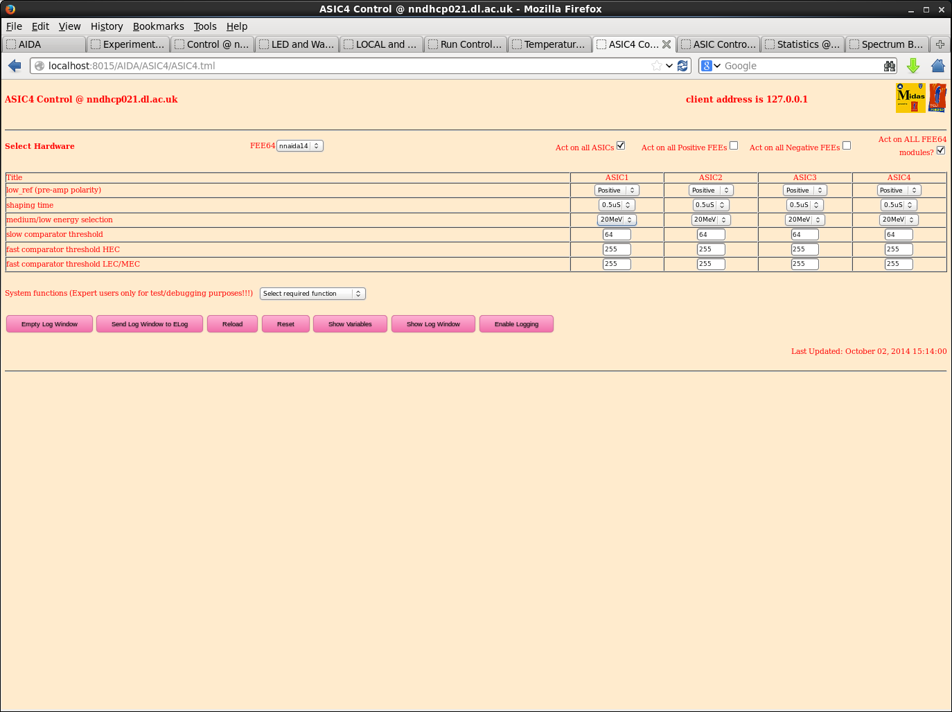
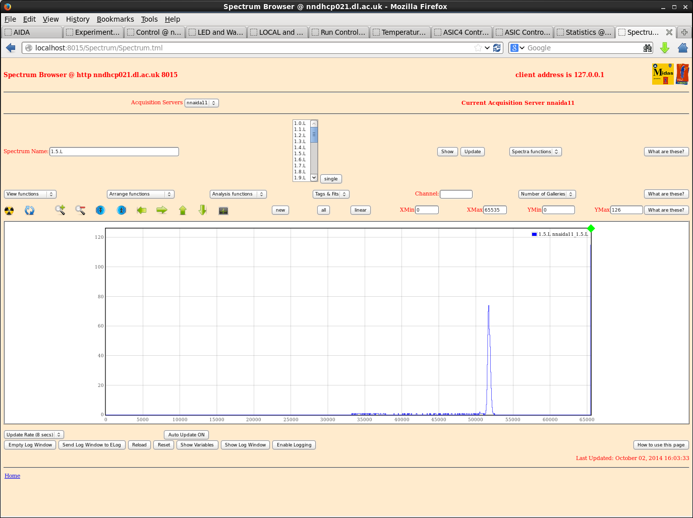
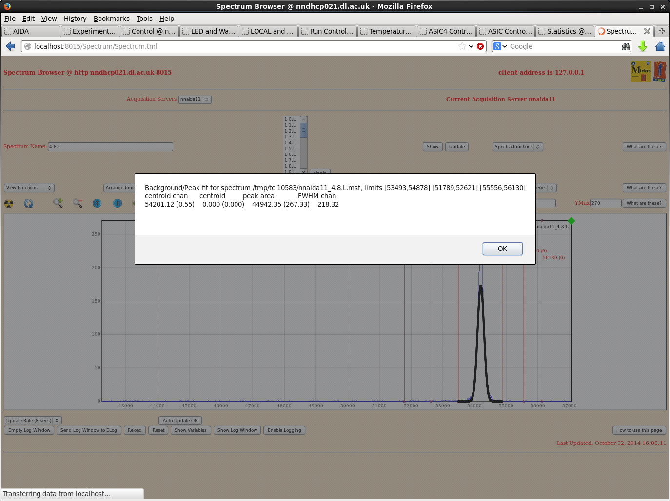
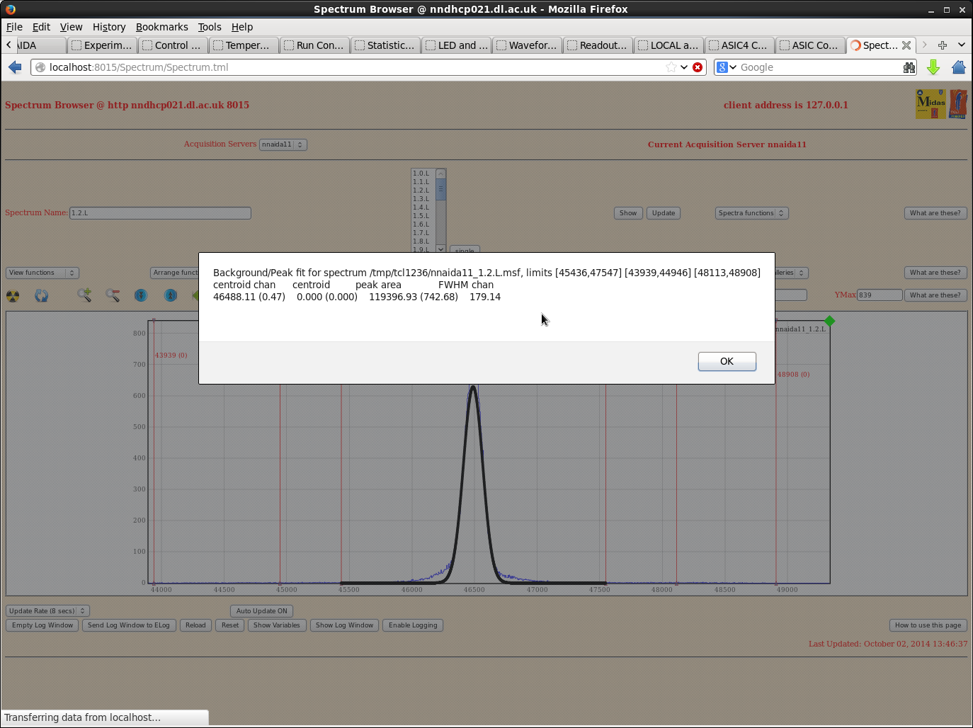
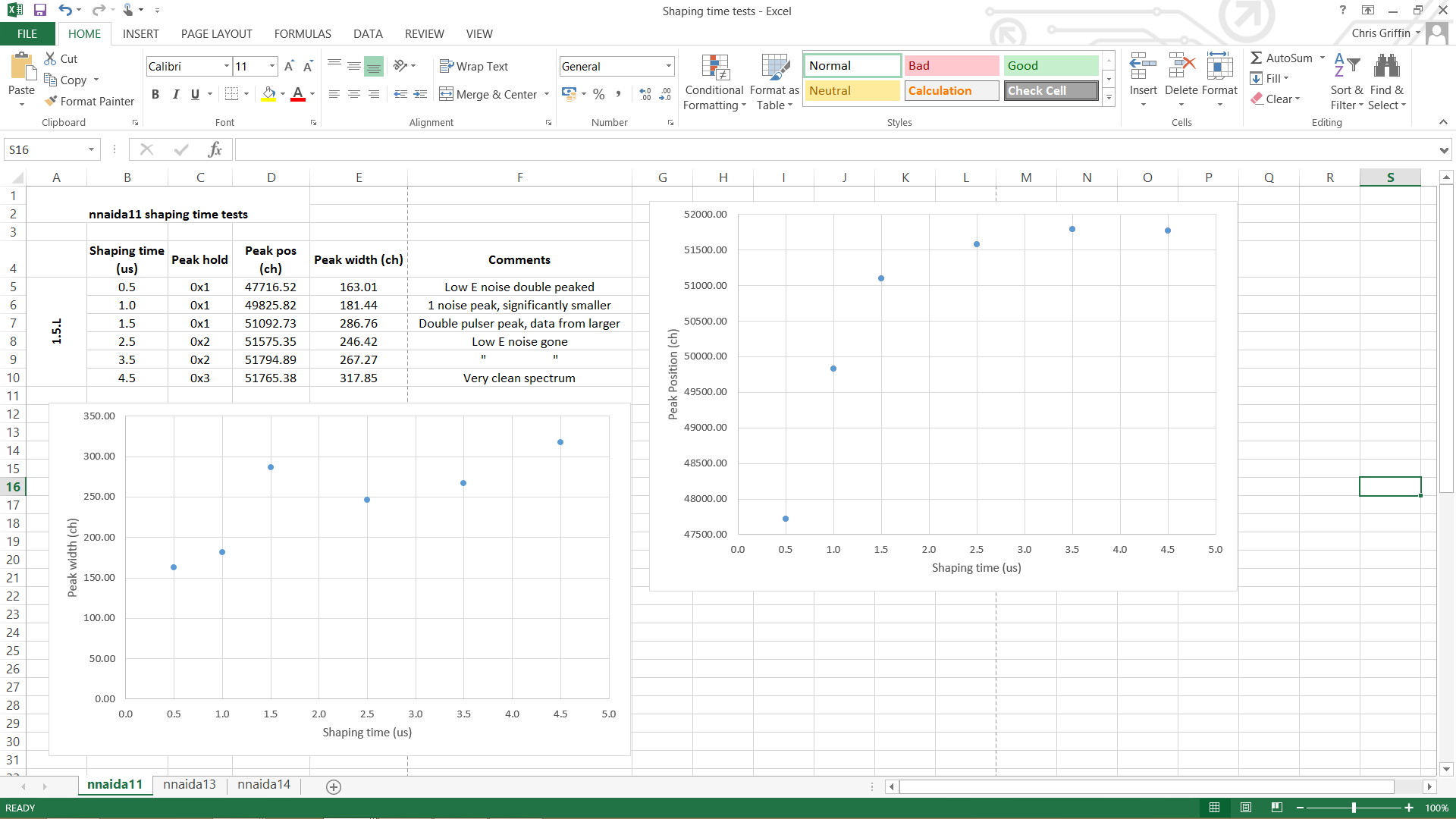
I varied the shaping time in each module using the ASIC4 control page as this also changes the hold time automatically. Slow comparitor threshold of 64.
Checked each module and took sample channels from a couple of ASICs in each but made qualitative comparisons with random channels in all ASICs to make sure the chosen ones were representative of the ASIC/module as a whole.
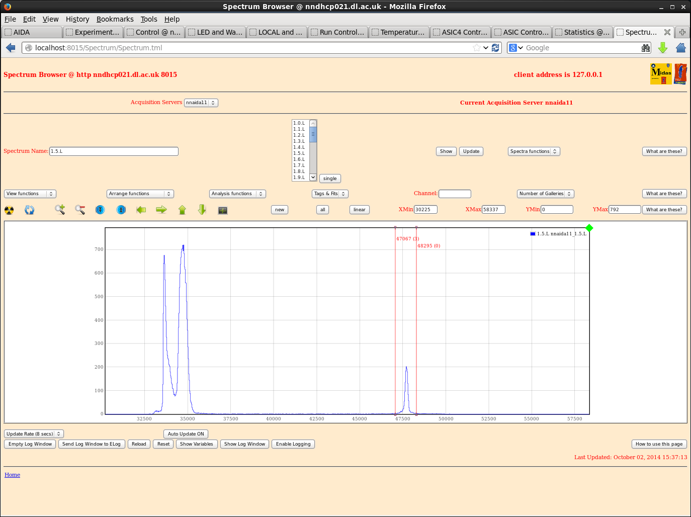
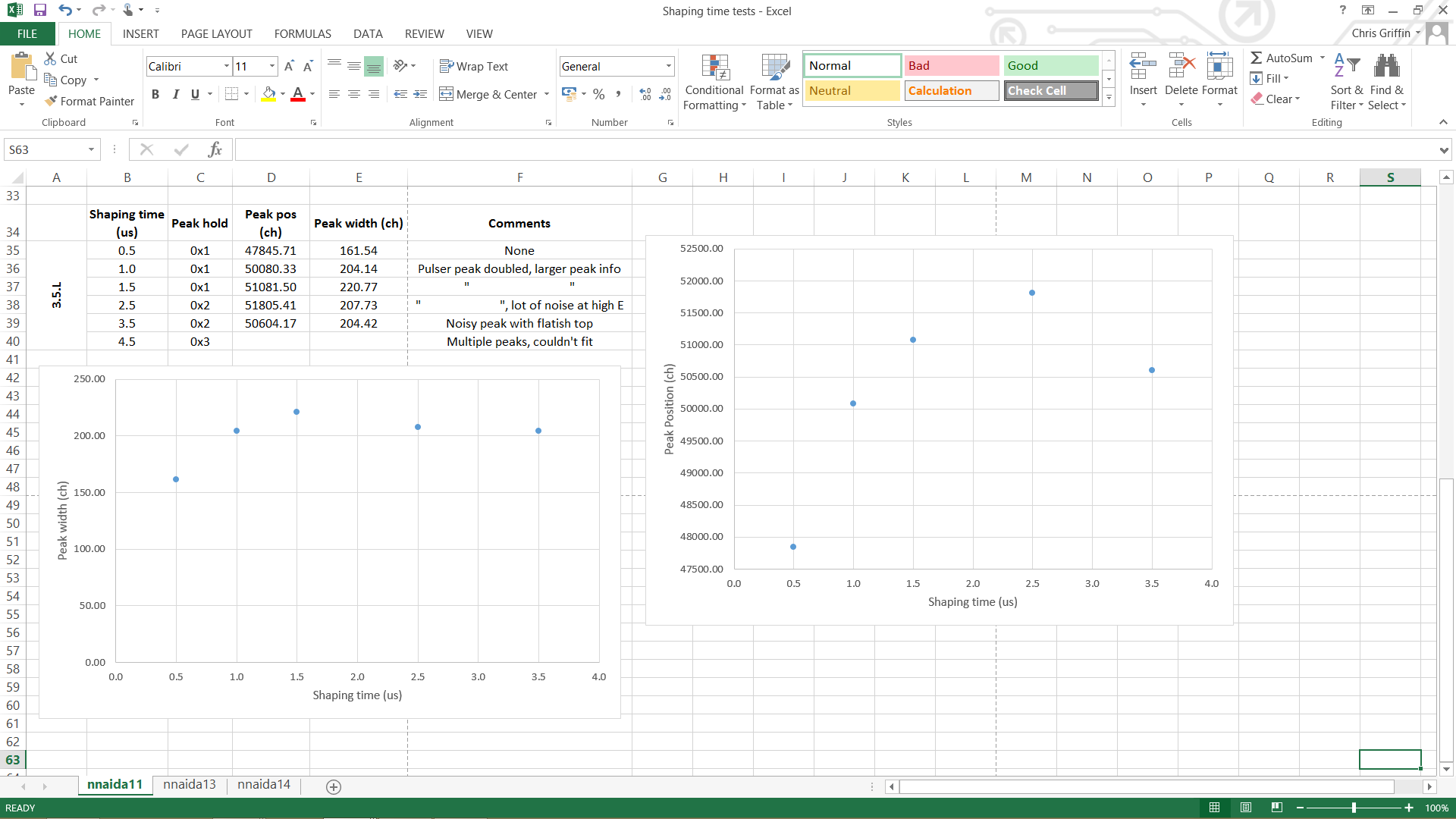
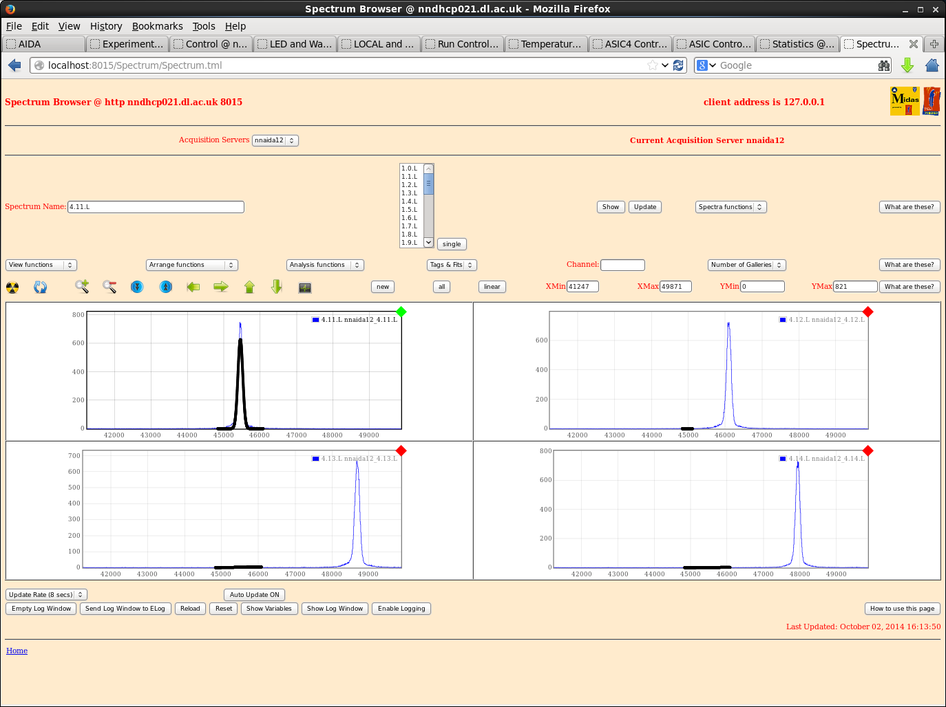
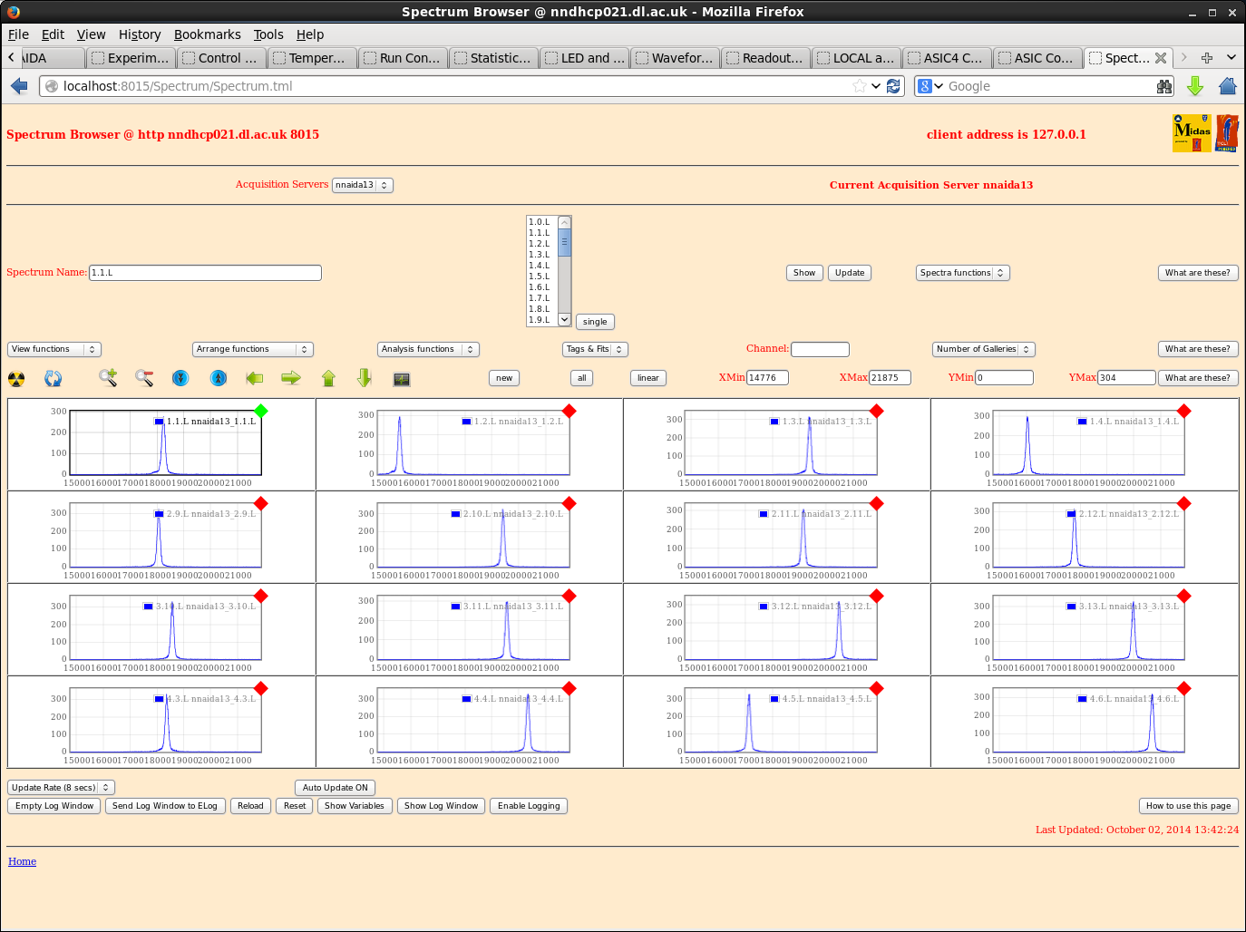
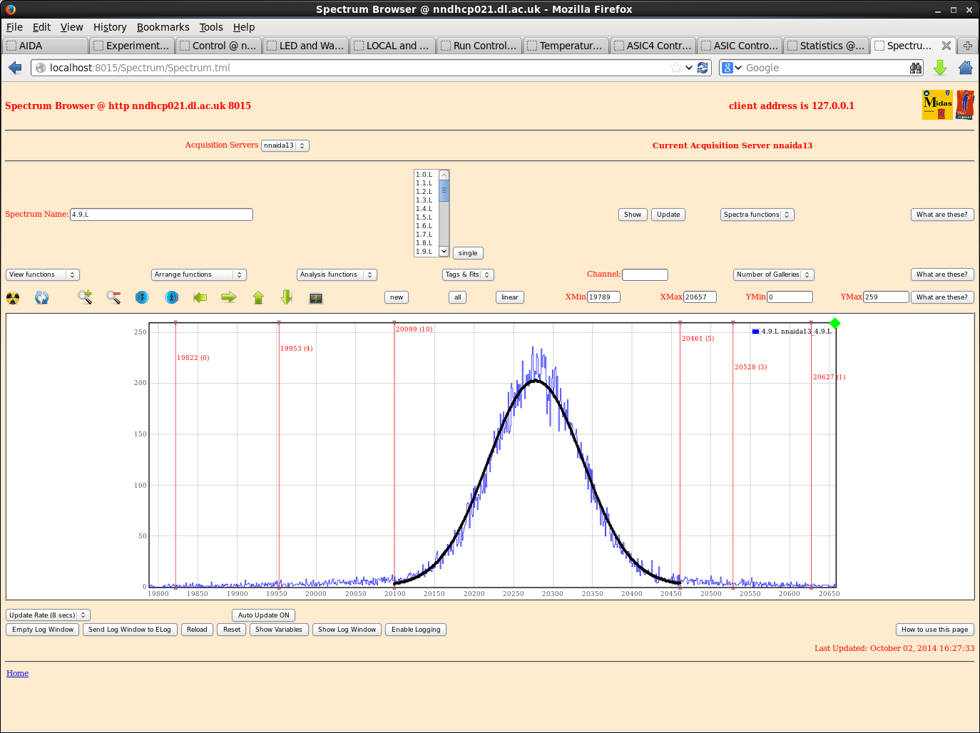
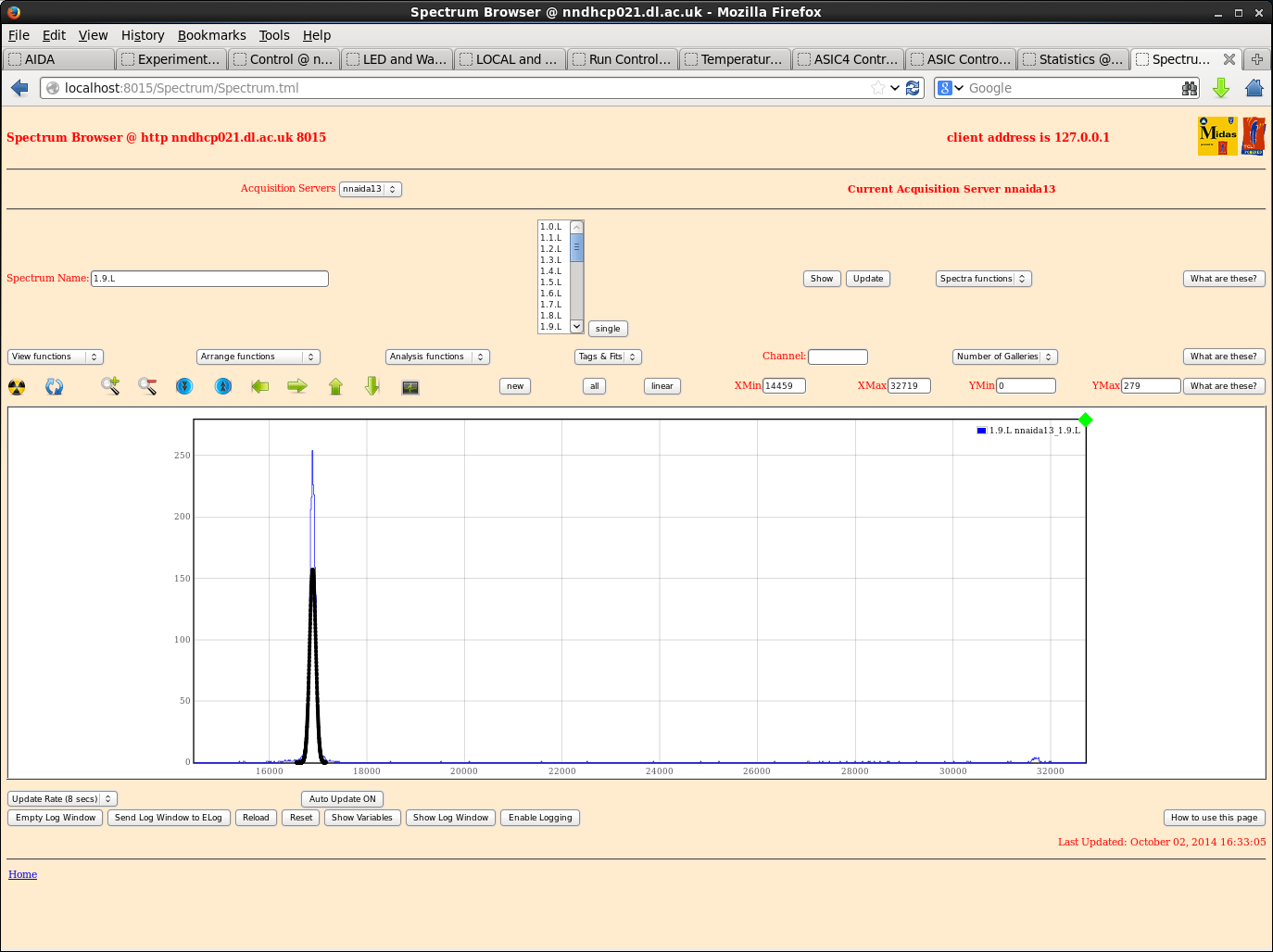
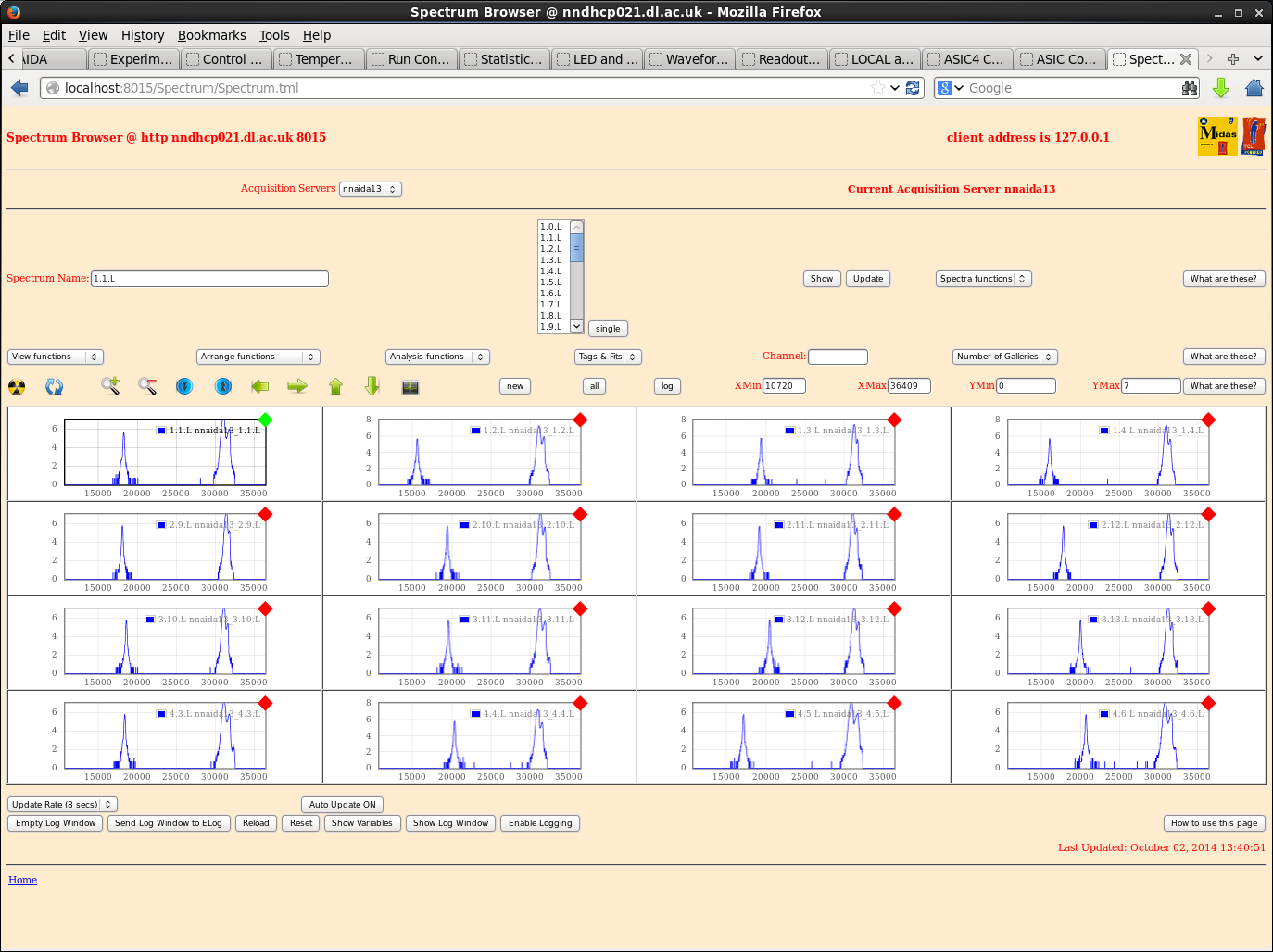
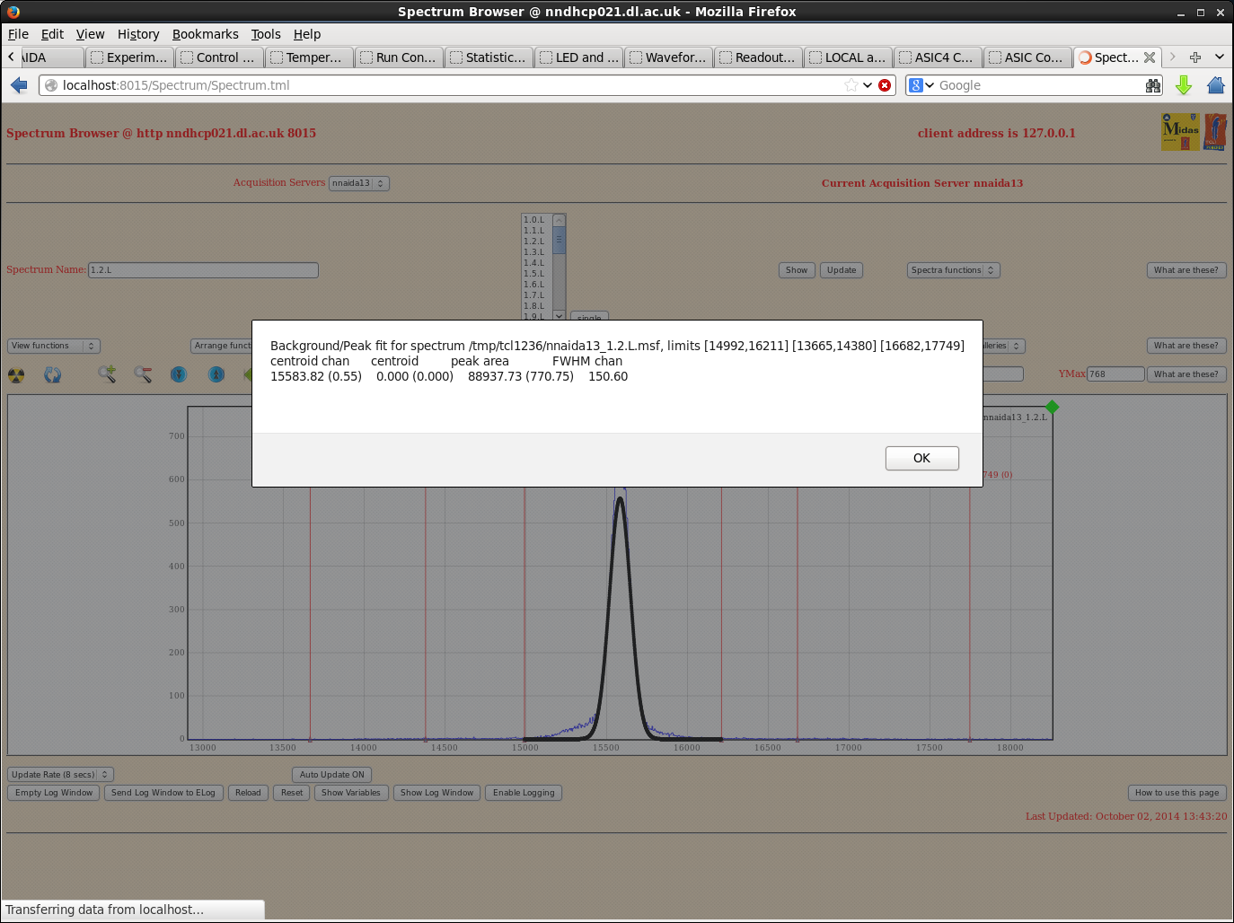
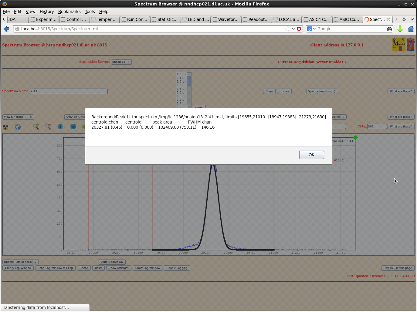
Tables and graphs are included below for nnaida11 and 13. nnaida13 showed a high level of low E noise on some spectra, but the pulser peaks were always well defined single peaks.
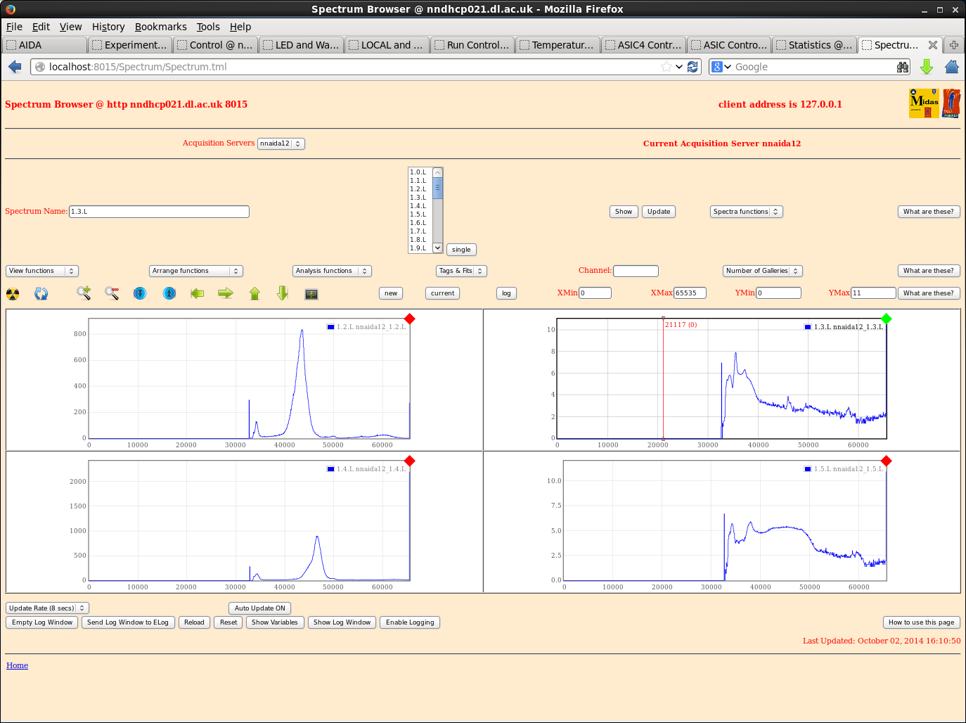
nnaida12 showed noises across the full range of many spectra in all ASICs apart from ASIC4. Patrick suggested this module may possibly be suffering and need replacing. A quick scan through some channels showed:
- average peak width @ shaoing time of 0.5us of ~150-180 ch
- same at shaping times of 2.5 and 4.5us. Noise present over full range throughout
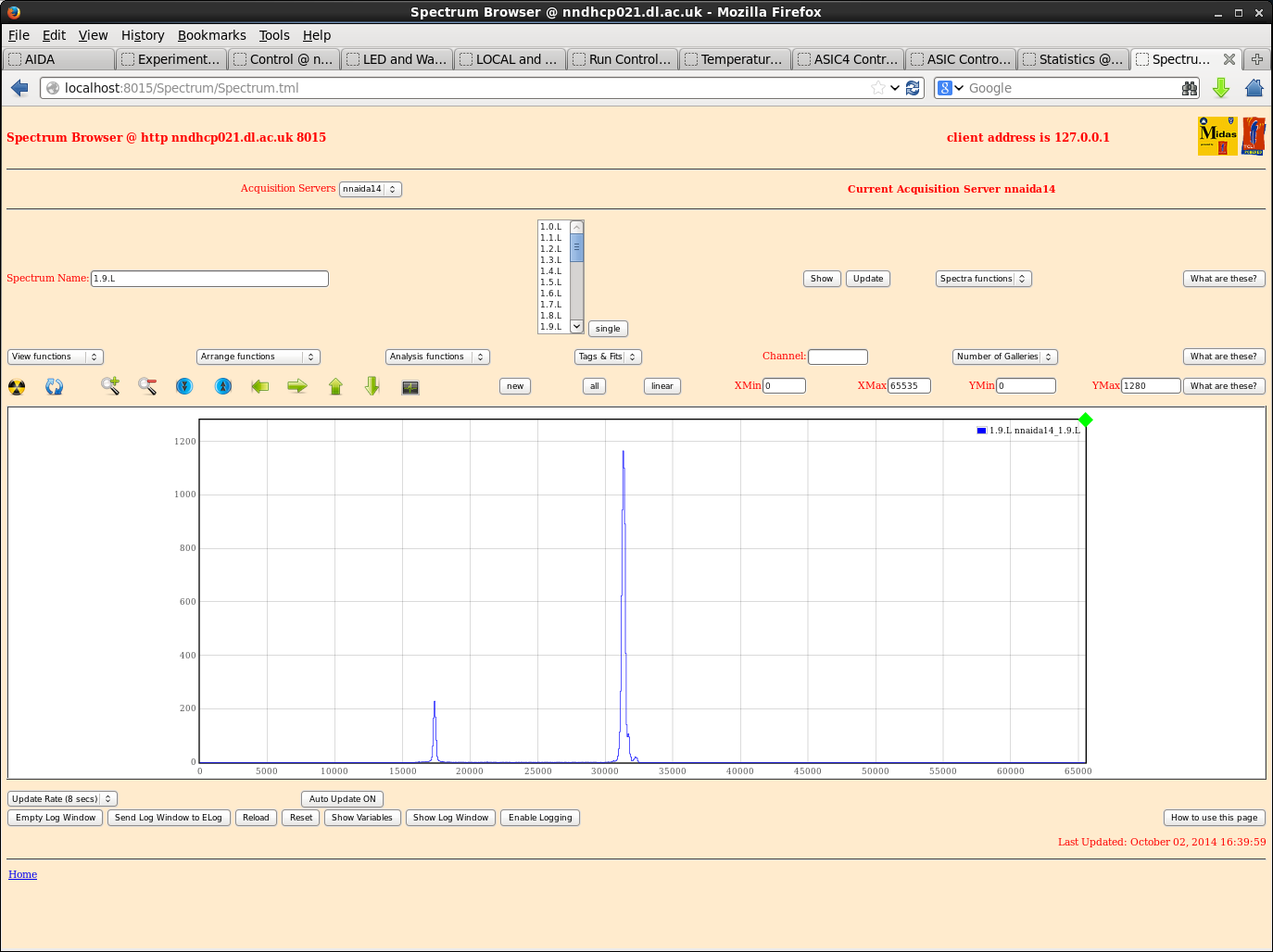
My taxi was arriving so I didn't have chance to go through nnaida14 in depth, but a quick scan showed peak widths within ~10-15ch of those seen in nnaida13. |
| Attachment 1: ASIC4control-orig.png
|
|
| Attachment 2: nnaida11-SY1527spec.png
|
|
| Attachment 3: nnaida11-SY1527_2.5stWide.png
|
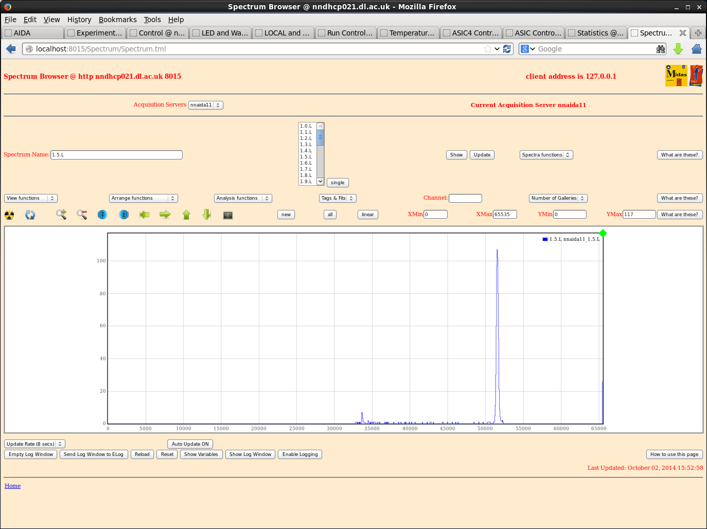
|
| Attachment 4: nnaida11-SY1527_4.5st.png
|
|
| Attachment 5: nnaida11-SY1527_4.8.Lpeak3.5st.png
|
|
| Attachment 6: nnaida11-Sy1527peakEx.png
|
|
| Attachment 7: nnaida11-1.5.L-excel.png
|
|
| Attachment 8: nnaida11-3.5.L-excel.png
|
|
| Attachment 9: nnaida12-SY1527_FSnoise.png
|
|
| Attachment 10: nnaida12-SY1527good.png
|
|
| Attachment 11: nnaida13-SY1527peaks.png
|
|
| Attachment 12: nnaida13-SY1527_0.5st.png
|
|
| Attachment 13: nnaida13-SY1527_1.5st.png
|
|
| Attachment 14: nnaida13-SY1527noise.png
|
|
| Attachment 15: nnaida13-SY1527peakEx.png
|
|
| Attachment 16: nnaida13-SY1527peakEx2.png
|
|
| Attachment 17: nnaida14-SY1527_1st.png
|
|
|
15
|
Thu Oct 2 15:23:38 2014 |
Patrick Coleman-Smith and Chris Griffin | Trial with Filtered AIDA PSU |
Assembled three more of the filter boards and installed them in the AIDA PSU with the first, wired to use the switchmode power supply.
Powered up nnaida14 first and went fine. Just the boot sequence and measure the voltages for stability.
Powered up the remainder and all was well.
Setup and go..... the rates were way too high in all of them.
nnaida12 was running at 200k/sec+ most of the time.
The other three could be reduced in rate by changing the slow comp thresh as would be expected but 12 wasn't any good.
Tried:
Remove MACB HDMI.... no good
isolate psu earth from NIM crate ( put psu on foam support ) ..... no good
Checked the filter output and the sine wave reported yesterday ( nnaida2 ) was present on all voltage rails but no evidence of high frequency noise.
Set all channels to 1GeV, with Slow comp thresh of 10, and 11,13 & 14 showed roughly the same rate of 10 to 15k/sec. Peaks in the spectra were FWHM 12 at a random sample. nnaida12 would not conform.
Changed back to the bench power supply connections so Chris can continue. |
|
14
|
Wed Oct 1 18:37:42 2014 |
Chris Griffin | 01/10/2014 Tests @ DL |
Kept largely the same settings at the entry https://elog.ph.ed.ac.uk/AIDA/4
Same ASIC settings
Emco used to provide HV
HV+ --> nnaida11 & nnaida12 (p+n strips, -ve pulser input)
HV- --> nnaida13 & nnaida14 (n+n strips, +ve pulser input)
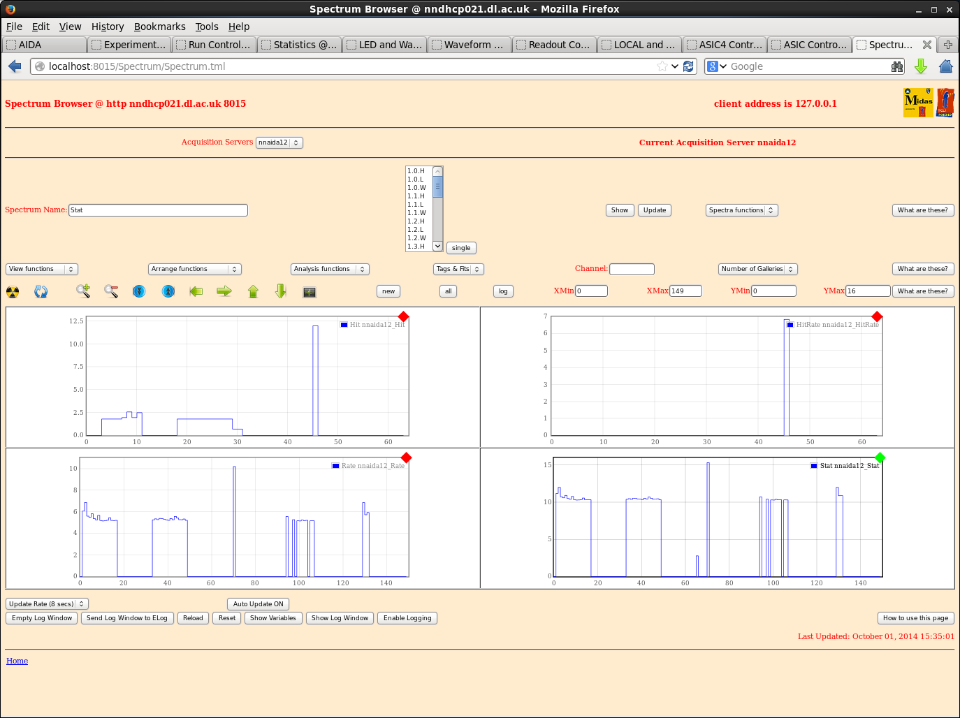
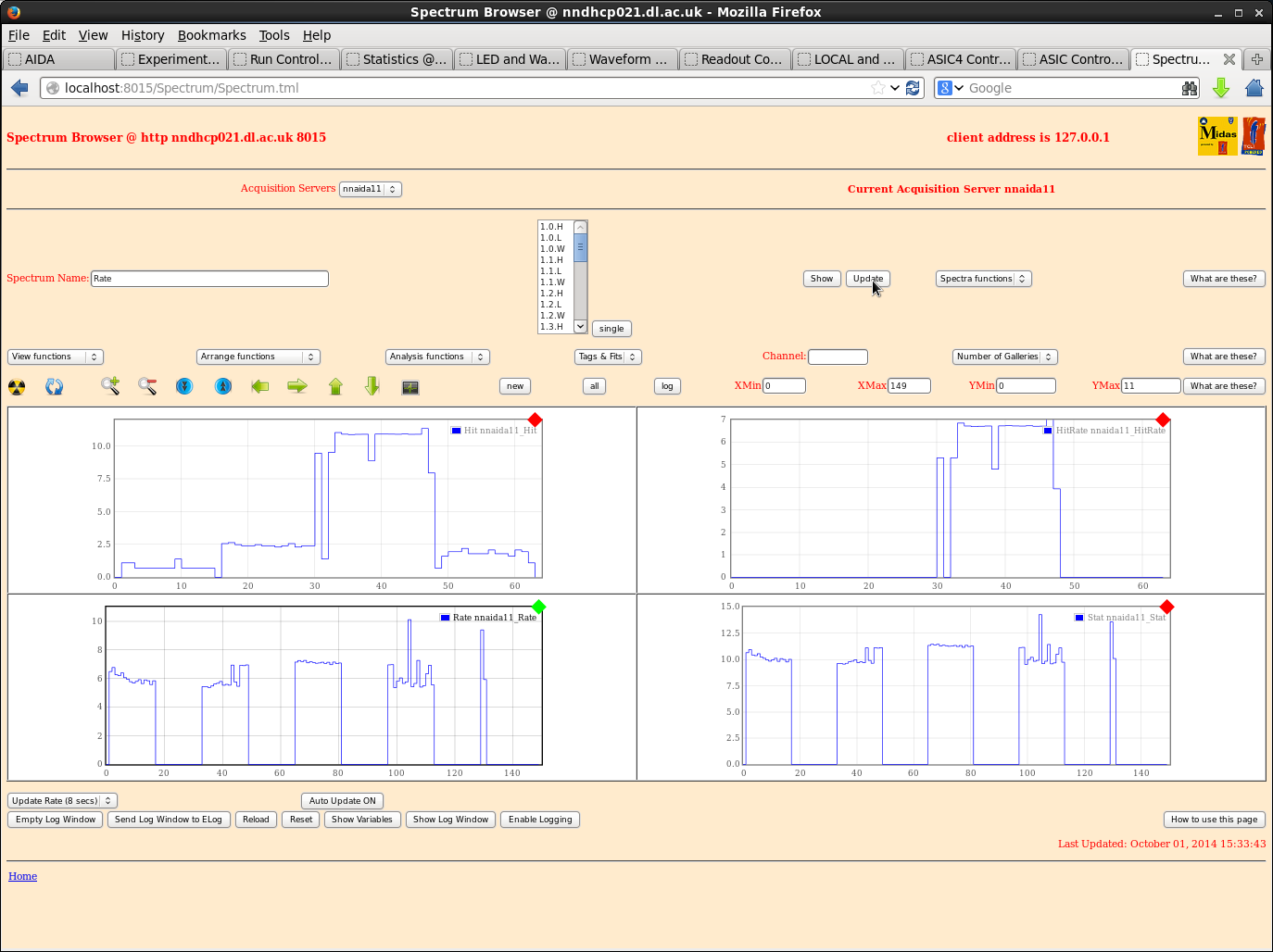
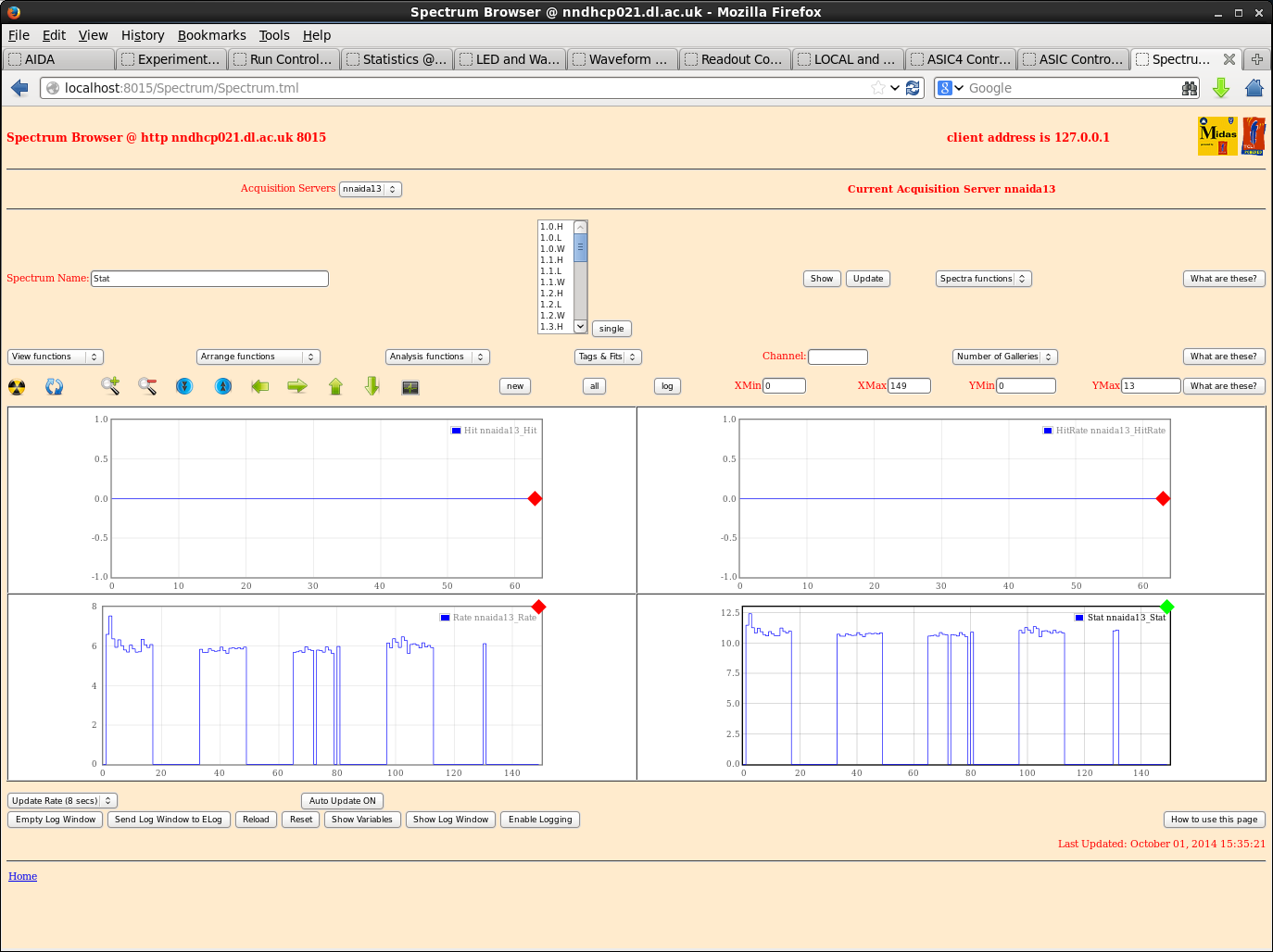
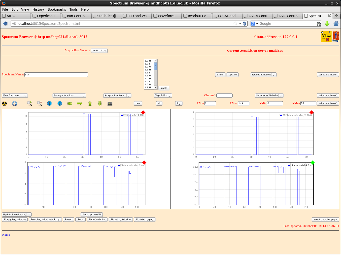
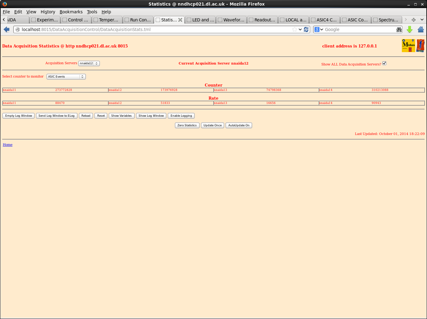
Stat spectra look roughly the same as those included in the above entry.
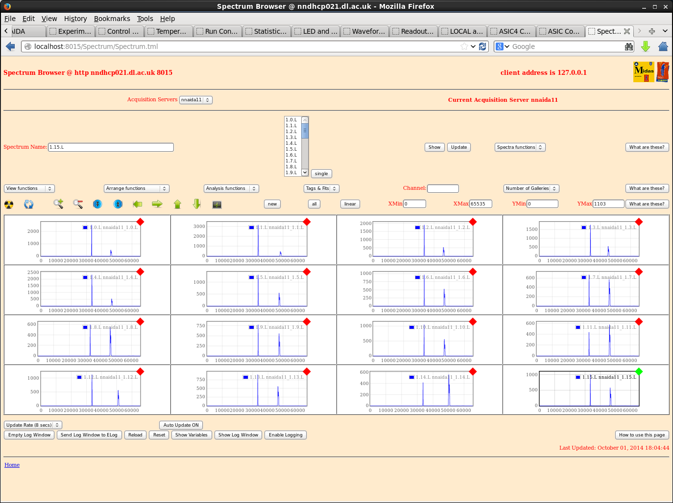
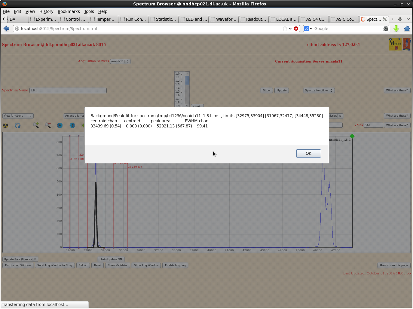
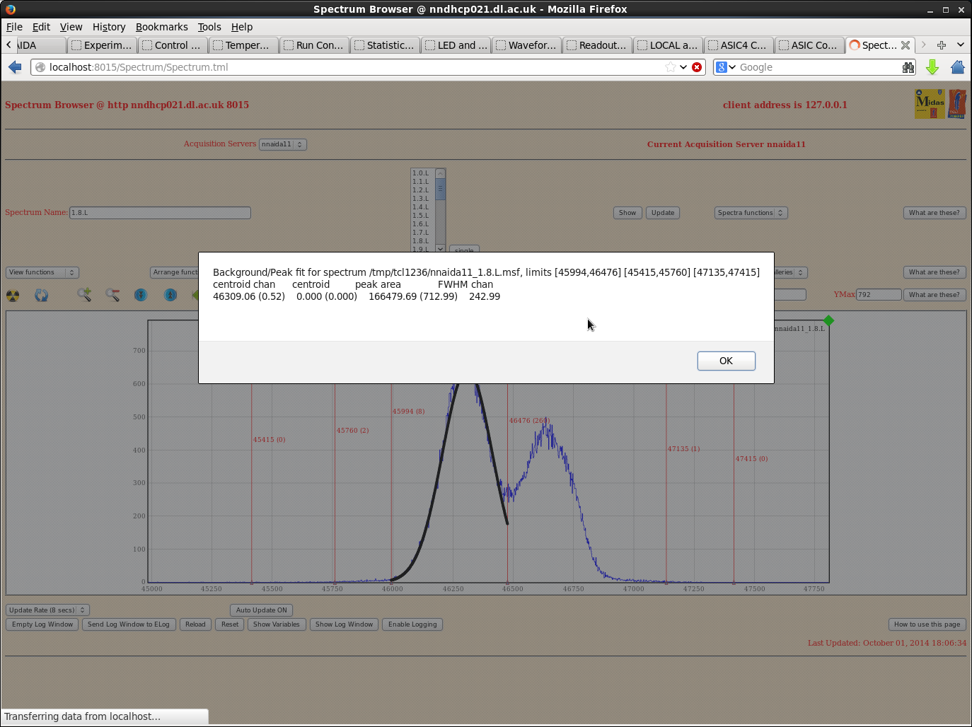
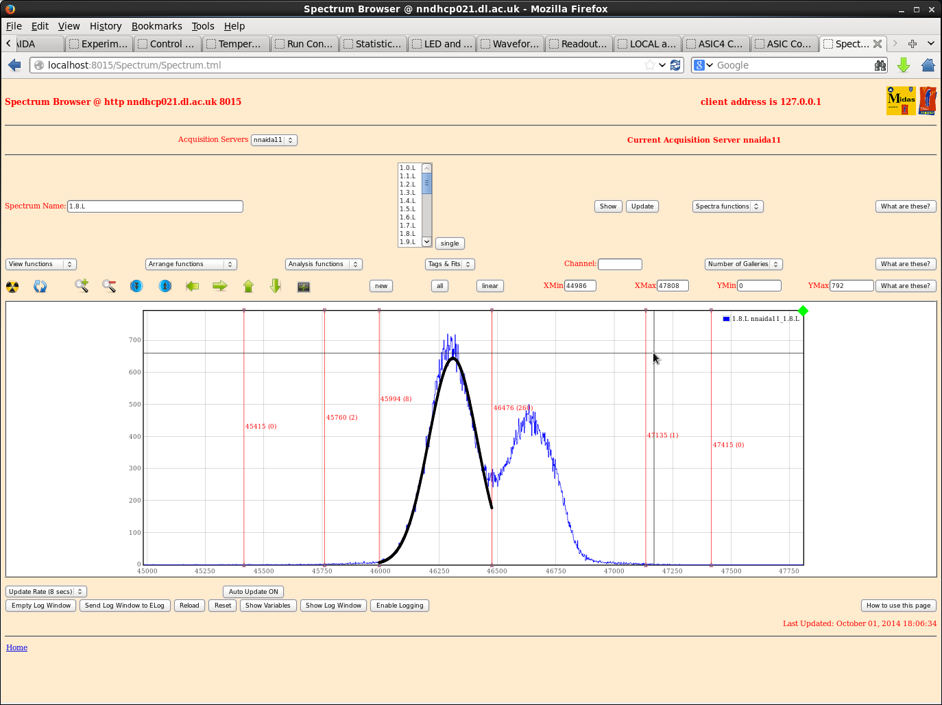
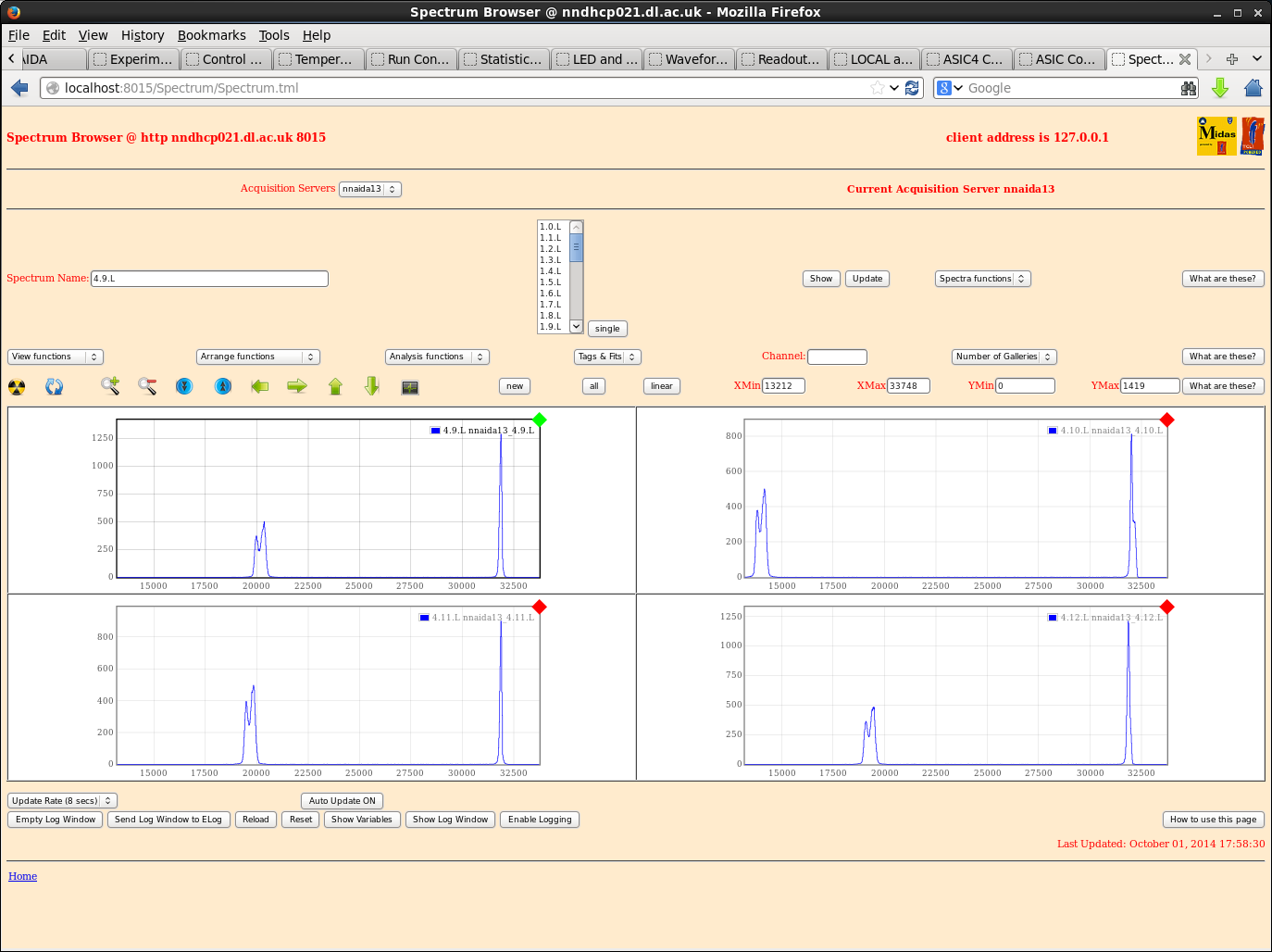
Now see large peak around ~32k, present in all spectra to some degree. Mostly larger than corresponding pulser peak.
Power cycled several times, reloaded+checked ASIC settings etc., no change. Any ideas? Have I forgotten something?
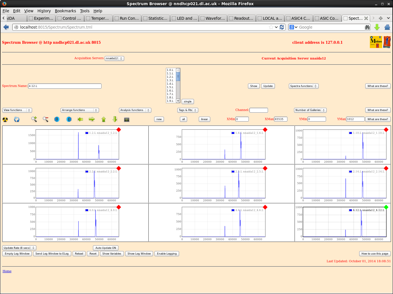
The ASIC events stats rate is also very high on nnaida11,12,14. 13 is high but not excessively.
Pulser peak shows double peaking on all ASIC channels with individual widths of ~250ch and total width of ~500ch.
Noise peak has width ~50ch. This has reduced somewhat (was ~100s ch) with my last power cycle, but clearly still not gone.
I'll try again in the morning, but if no change will proceed with the shaping time tests with the spectra as they are.
|
| Attachment 1: nnaida12_stats.png
|
|
| Attachment 2: nnaida11_stats.png
|
|
| Attachment 3: nnaida13_stats.png
|
|
| Attachment 4: nnaida14_stats.png
|
|
| Attachment 5: nnaida11_allnoise.png
|
|
| Attachment 6: nnaida11_noisefit.png
|
|
| Attachment 7: nnaida11_peakfit.png
|
|
| Attachment 8: nnaida11_peakfit2.png
|
|
| Attachment 9: nnaida12_few.png
|
|
| Attachment 10: nnaida13_asic4_noise.png
|
|
| Attachment 11: ASICevents_stats.png
|
|
|
13
|
Wed Oct 1 15:41:07 2014 |
Patrick Coleman-Smith | Power supply filters #3 |
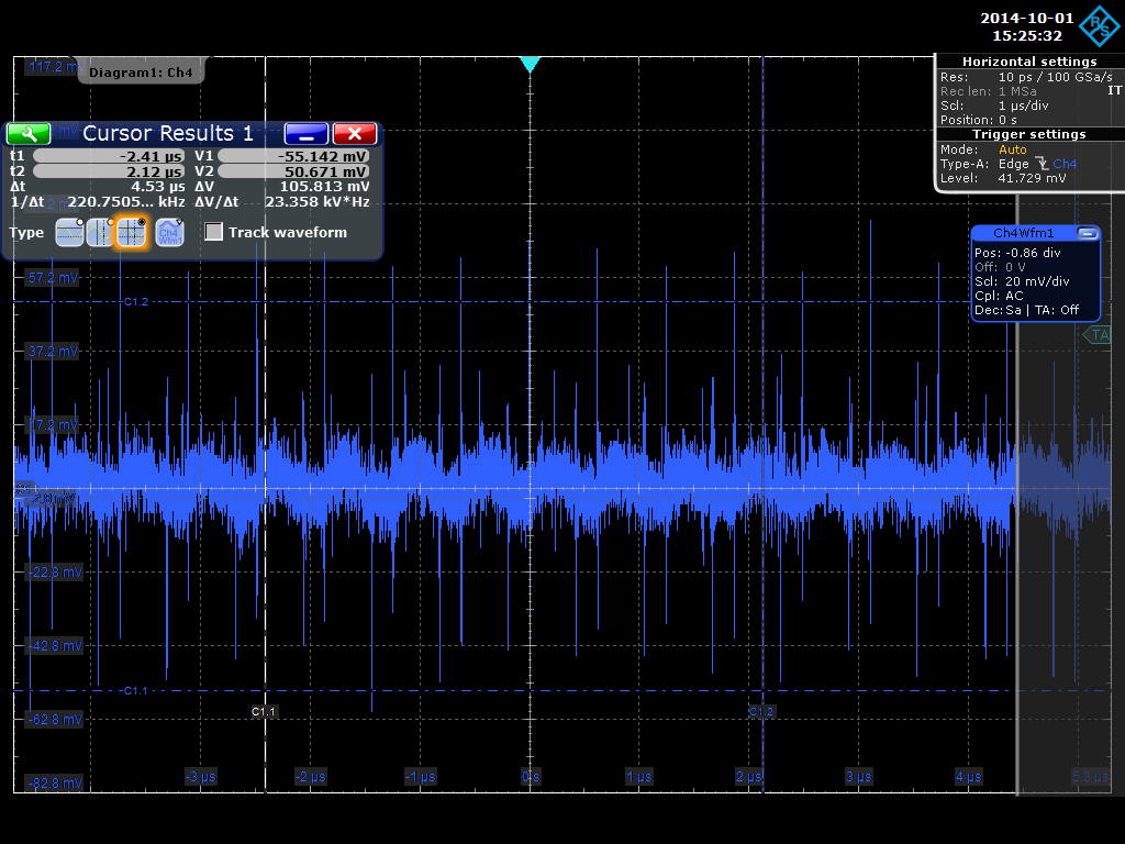
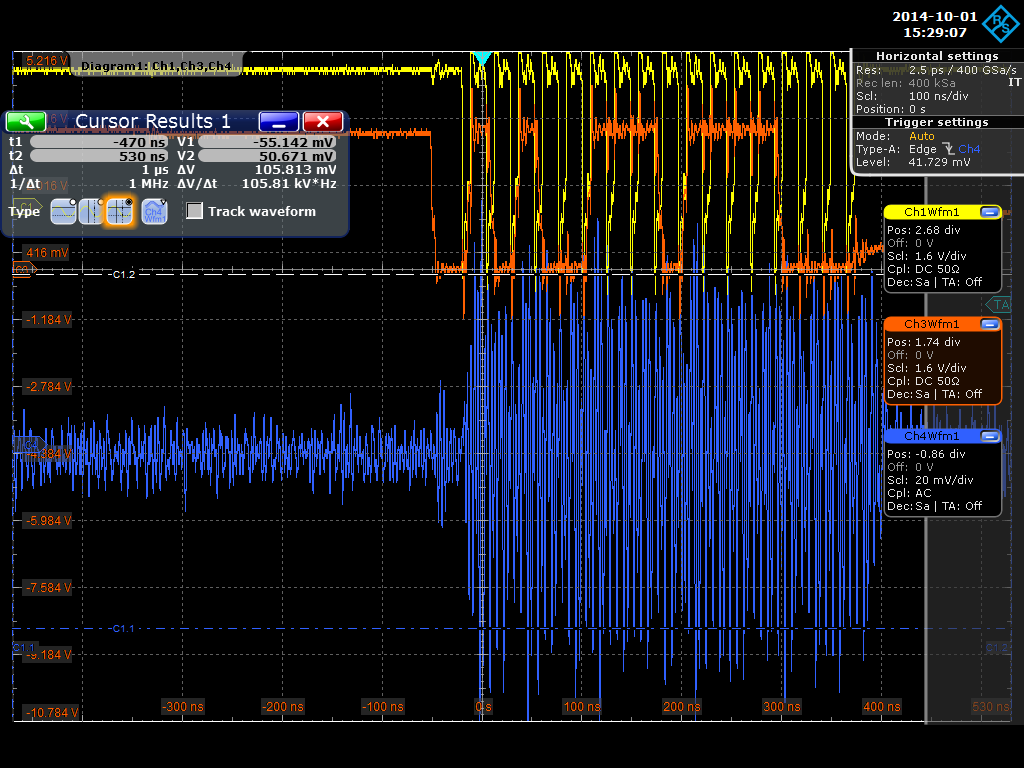
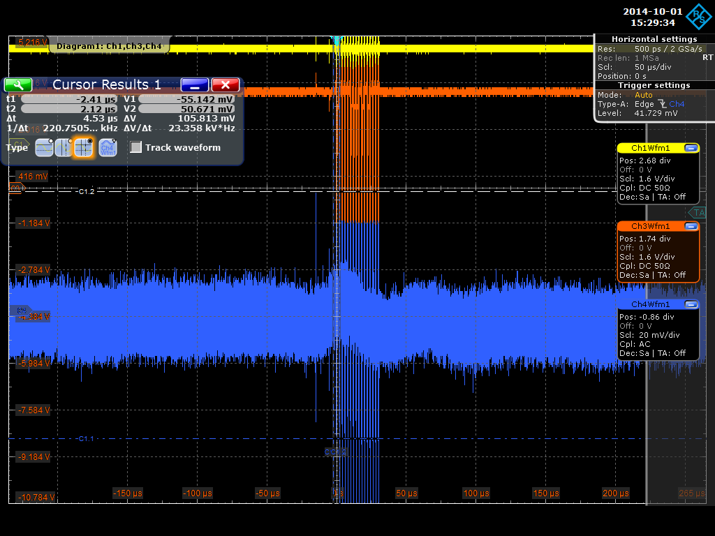
Measuring the signal at the FEE64 end.
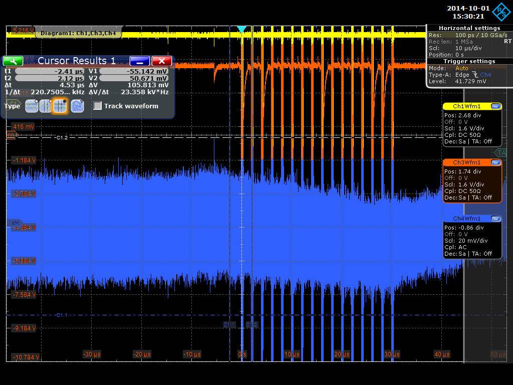
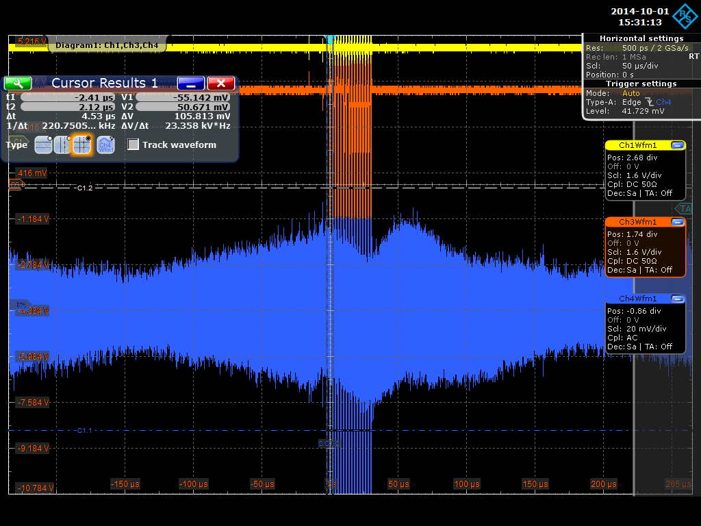
+5v , -6v , +7v, +7v
The two other 'scope channels are connected by FET probes to the FEE64. I now see there is a ground connection.... so i will remove it and re-measure the signals in the filter.
No real difference.
Measuring at the FEE64 and the spikes when the Mux ADC is reading out have disappeared. |
| Attachment 1: RTOScreenshot_2014-10-01_17_152532.png
|
|
| Attachment 2: RTOScreenshot_2014-10-01_18_152907.png
|
|
| Attachment 3: RTOScreenshot_2014-10-01_19_152935.png
|
|
| Attachment 4: RTOScreenshot_2014-10-01_20_153021.png
|
|
| Attachment 5: RTOScreenshot_2014-10-01_21_153113.png
|
|
|
12
|
Wed Oct 1 15:15:32 2014 |
Patrick Coleman-Smith | Power supply filters |
2.0.L FWHM:14.26
2.15.L ( 270pF ) FWHM : 119.04
(ooops found the 'scope channel was on 20Mhz BW filter )
DC measurements.
At FEE64 :- +7.822 , -6.36, +4.937
at Filter output ( AIDA Cable input ) :- +7.96, -6.46, 5.37
at filter input:- +7.97, -6.476, +5.488
Set supply with these voltages and add filter.
Measured earth point to mains earth pin as 0.095ohms.
Power-up with nnaida2. ADCs Calibrate fine....successful boot.
Voltages at FEE64:- +7.802, -6.324, +4.887. I will adjust the power supply voltages to match the FEE64 previous setup.
2.0.L FWHM :13.83
2.15.L FWHM:116.6
So not really a difference in performance at this simple level.
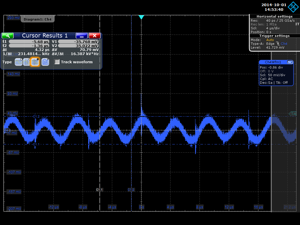
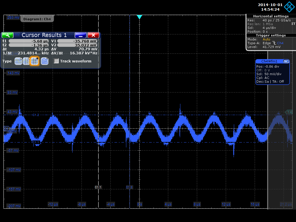
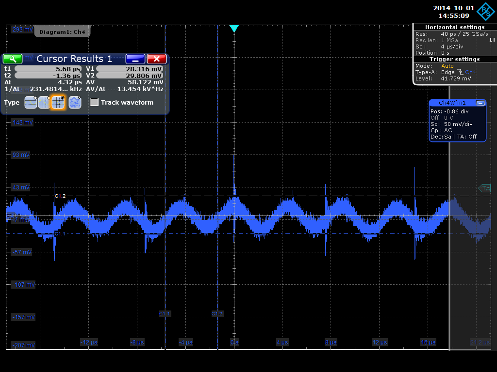
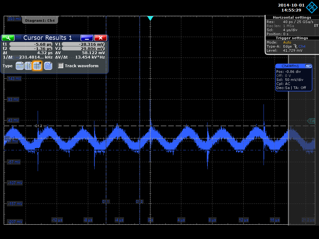
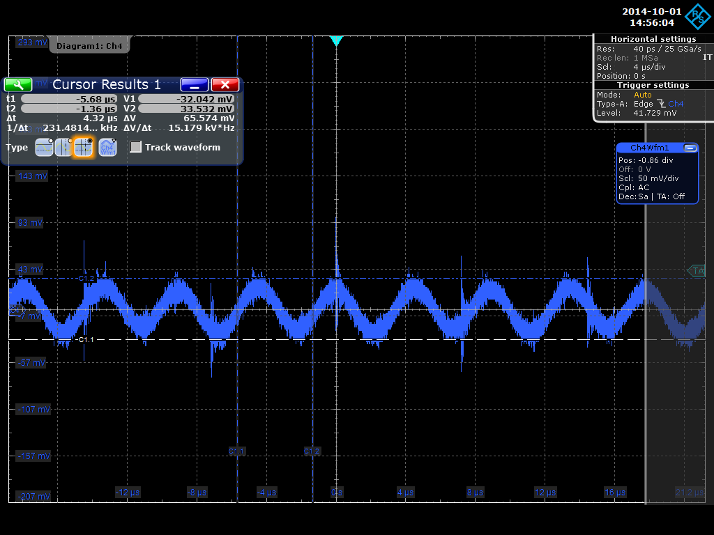
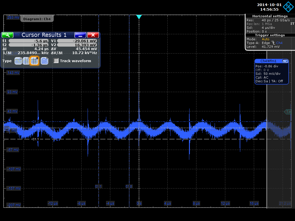
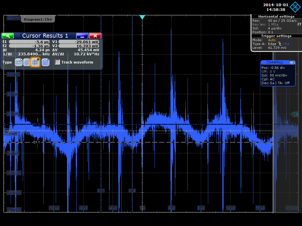
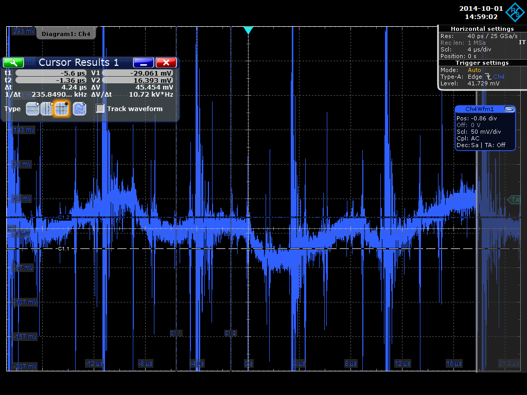
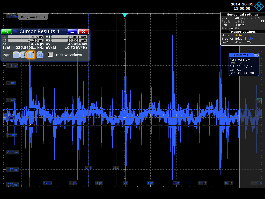
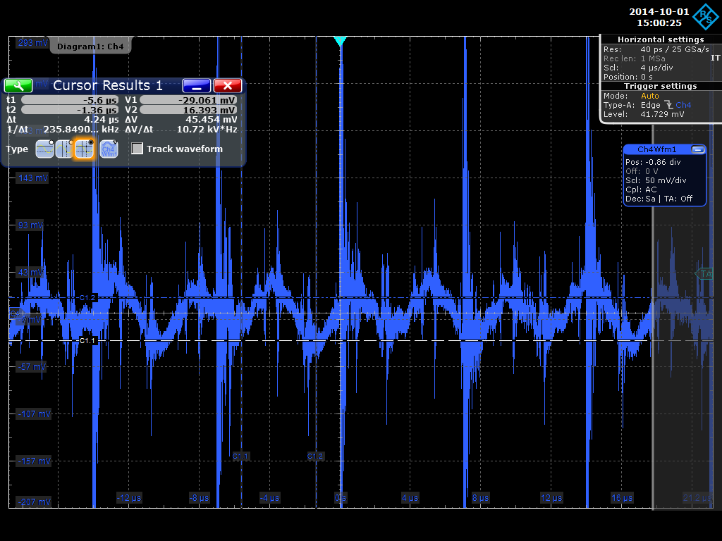
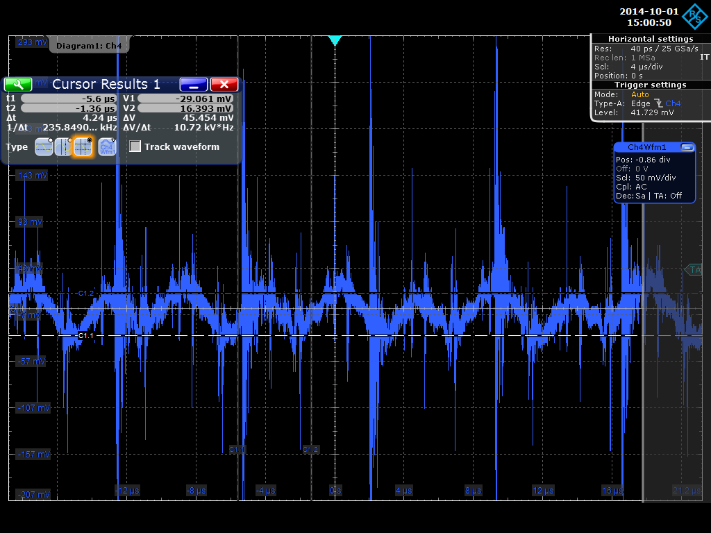
Attached are some oscilloscope traces of the six voltage rails after the filter on the filter board. +5v & 0v , -6v & 0v, +7v & 0v relative to the earth on the filter board.
Attached are some oscilloscope traces of the six voltage rails before the filter on the filter board. +5v & 0v , -6v & 0v, +7v & 0v relative to the earth on the filter board.
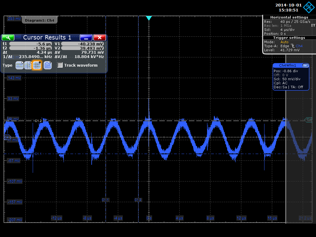
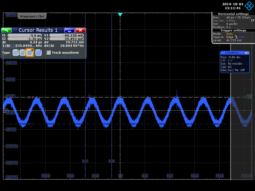
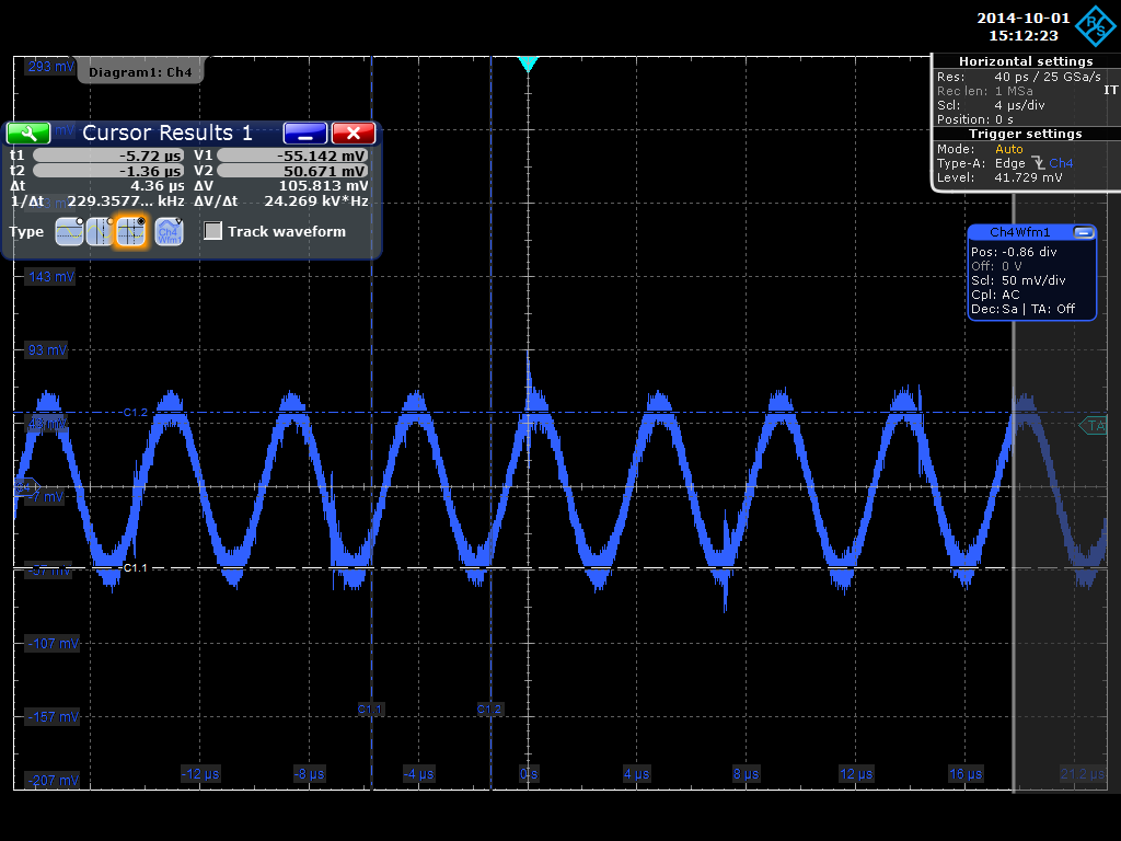
There is a nice sine wave at 235KHz that needs to be finished off perhaps. Otherwise the filter seems to be doing well.
Next set of 'scope traces are across the three supplies. +7v, -6v, +5v.
Sine wave is present ( 220KHz ) at 80mv, 80mv, 105mv.
Next I'll try this supply on nnaida12 ( detector negative ) ...... next entry ....
|
| Attachment 1: RTOScreenshot_2014-10-01_2_145340.png
|
|
| Attachment 2: RTOScreenshot_2014-10-01_3_145424.png
|
|
| Attachment 3: RTOScreenshot_2014-10-01_4_145509.png
|
|
| Attachment 4: RTOScreenshot_2014-10-01_5_145529.png
|
|
| Attachment 5: RTOScreenshot_2014-10-01_6_145604.png
|
|
| Attachment 6: RTOScreenshot_2014-10-01_7_145655.png
|
|
| Attachment 7: RTOScreenshot_2014-10-01_8_145838.png
|
|
| Attachment 8: RTOScreenshot_2014-10-01_9_145902.png
|
|
| Attachment 9: RTOScreenshot_2014-10-01_11_150000.png
|
|
| Attachment 10: RTOScreenshot_2014-10-01_12_150025.png
|
|
| Attachment 11: RTOScreenshot_2014-10-01_13_150050.png
|
|
| Attachment 12: RTOScreenshot_2014-10-01_14_151051.png
|
|
| Attachment 13: RTOScreenshot_2014-10-01_15_151141.png
|
|
| Attachment 14: RTOScreenshot_2014-10-01_16_151223.png
|
|
|
11
|
Wed Oct 1 13:28:03 2014 |
Patrick Coleman-Smith | Power supply filters |
The new pcb for the power supply filter arrived.
I assembled the components ( after finding the whoops ) and connected it to the bench power supply for nnaida2.
nnaida2 functions just about the same as before but the power supply filter results seem amazing.
I have measured the signals on the power supply before and after the filter.
The 'scope is referenced to earth on the filter board and this earth is connected to earth through the +5v@10A supply.
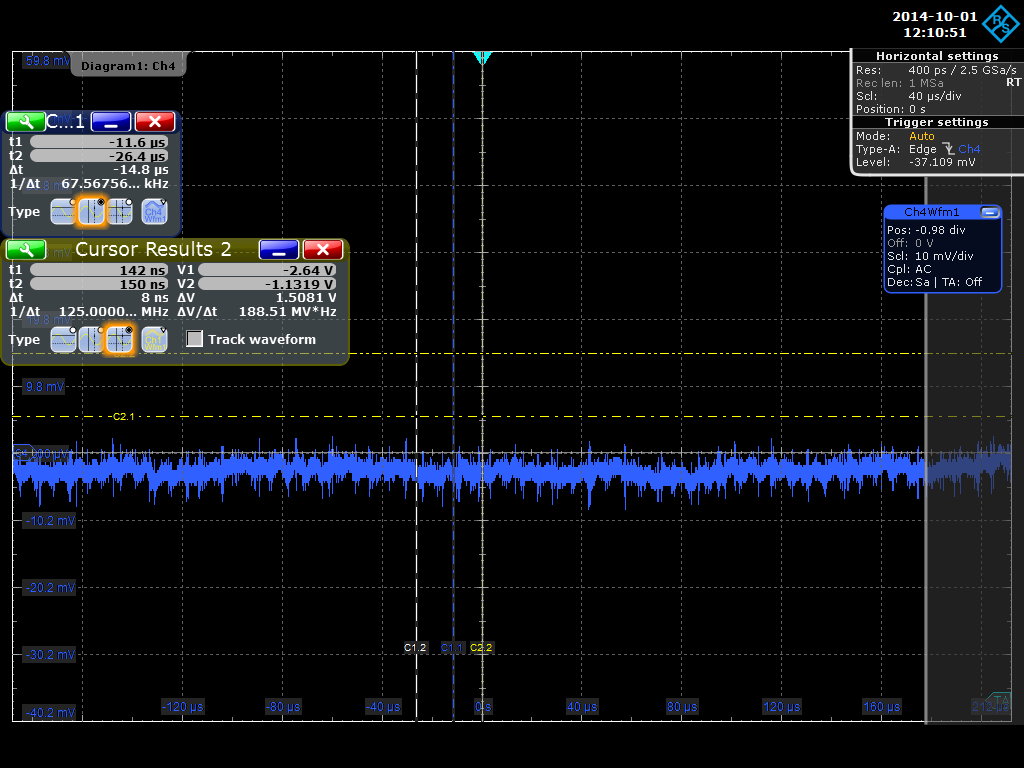
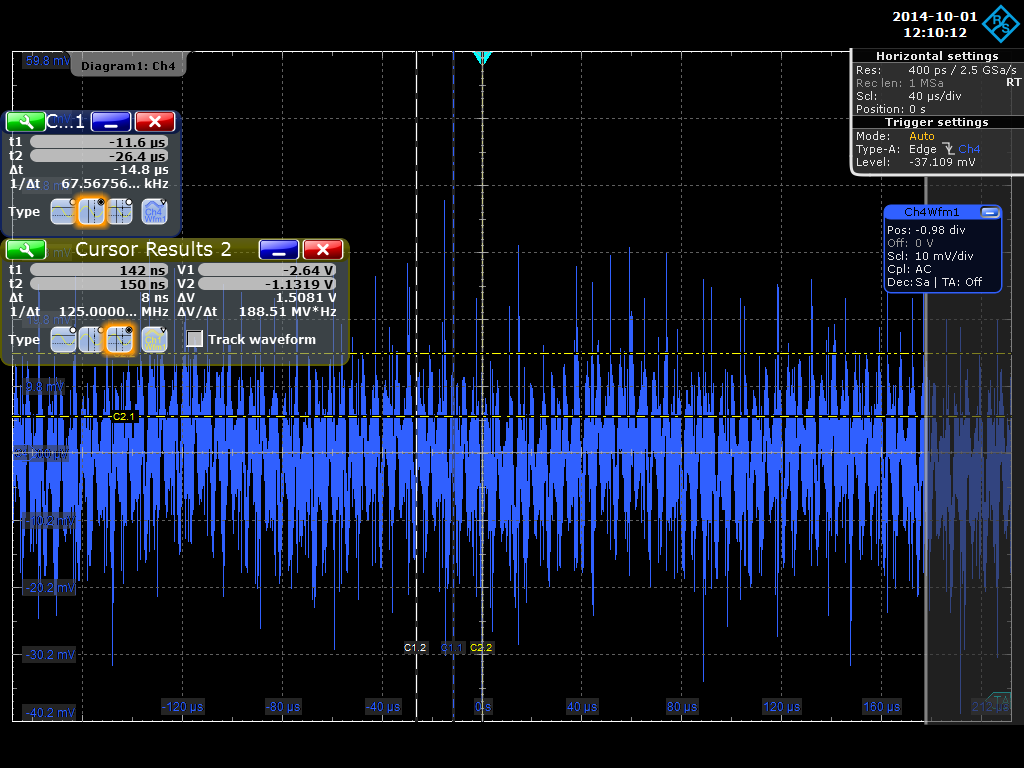
Before the filter the average noise on the rail ( AC coupled ) is 33mV and after is ....... 5mV pretty exciting stuff.
I have attached the two 'scope pictures.
The same measurements on the +7v, -6v and 0v rails give similar improvements.
The choke on the +5v rail measures 34 degrees C so care will need to be taken.
Next I will measure the voltage drops across the filter and decide on the correct voltage settings for the AIDA switch mode power supply.
Then install the filter into the supply and check ..... and check ......
|
| Attachment 1: RTOScreenshot_2014-10-01_1_121051.png
|
|
| Attachment 2: RTOScreenshot_2014-10-01_0_121012.png
|
|
|
10
|
Thu Sep 25 11:53:34 2014 |
Patrick Coleman-Smith | Backup a step to check ASICs |
Disconnected the adaptors with the detector.
Added the adaptors with the kapton cables only attached.
Connected the pulser outputs ( pos and neg ).
nnaida11,13 & 14 : Stat spectra are normal. Rates are 10k to 16k
nnaida12 has normal stat spectrum with ASIC3 only showing channel 5.
Power cycle and re-try.
No different.
Suggest change the Mezzanine on nnaida12 and ask for the ASIC to be replaced..... maybe visible signs of problem ? |
|
9
|
Thu Sep 25 11:35:18 2014 |
Patrick Coleman-Smith | Removing the MACB from the system |
I have been wondering if the 0v path from the FEE64s to the MACB where they are joined is a possible problem.
I have been contemplating an isolated LVDS interface for the 50Mhz clock to test the idea.
Fortunately i recalled the 50Mhz internal oscillator in each FEE64.
I have disconnected the FEE64s from the MACB and run them using their internal 50Mhz clok.
No apparent change in performance.....
With Detector on. Using 'little block' HV supply. 11&12 with pre-amp ref set at 0x30.
The rates are as follows:-
nnaida11: 19k
nnaida12: 52k
nnaida13: 10k
nnaida14: 10k
The stat spectra of 13 & 14 look ok.
The stat spectra of 11 and 12 are strange and noisy but not "mad".
Maybe when the power supply filters are in place this can be revisited
|
|
8
|
Mon Sep 22 09:34:37 2014 |
Patrick Coleman-Smith | Clue to difference between ASICs 1&2 and 3&4 |
While investigating a VHDL conundrum I have noticed that the Mux ADC serial readout clock has a 'FAST' slew rate on ASICs 1&2 and a normal slew rate on ASICs 3&4.
Is it possible that the higher slew rate is actually better filtered by the ASIC de-coupling etc than the slower one.
Unfortunately I can't try this out yet as the "conundrum" means the VHDL version isn't good enough just yet.
Hopefully today.....
Patrick |
|
7
|
Thu Sep 18 11:18:46 2014 |
Patrick Coleman-Smith | Trying the Liverpool HV supply |
The SY1527 supply was delivered with three modules.
A cable has been made with LEMO00 connectors to connect to the detector adaptor HV inputs.
The SY1527 needed an external VGA display and ps2 keyboard. The software appears to be windows 98 based and won't boot until the bios is told to ignore drive D.
On boot the Drive A must be skipped. I will provide training when others wish to use the system 
Channel 0 is being used and has been tested with a voltmeter to provide the correct voltage at the LEMO00 connections. The control seems to be reliable and trips with over current.
200 volts has been applied to the detector with a final current of 3.9uA. The ramp up/down rate is 1V/second.
The acquisition system was run with pulser OFF and reference setting of 0x30 on the two negative modules nnaida11 and 12.
The rates were 130K/sec + on both the 11 and 12.
Run down the HV and add a 'scope probe ( 10MR and 11pF ) .
Run up and the 'scope shows 20mv pk-pk mushy noise with occasional 200mV+ bursts.
The acquisition performance did not improve.
Changed the reference on 11 and 12 to 0x90 and switch on the pulser then the rate became 20K to 25K. Stat spectra show that ASIC3 and 4 on these boards are still more active than 1 & 2.
Changed the reference on 11 down to 0x40 and Stat spectrum shows ASIC 3 and 4 become more active.
Added an R/C filter at the HV iput to the adaptor board. Removed the 'scope probe. The filter is the same as used with the HV supply in a box block from PorgamRays.
No real improvement.
Changed 11 & 12 reference back to 0x90.
Waveforms in 12 seem normal.
Back to working on the VHDL changes now.
|
|
6
|
Mon Sep 15 13:51:28 2014 |
Patrick | Odd spectra from running nnaida2 for 3 hours |
I'm running nnaida2 with the PB-5 and an old adaptor.(1pF)
I've seen spectra like this before but previously they have shown apparent digital relationship between the troughs.
So maybe they show 3 peaks ?
If so I don't quite understand the mechanism......
I just realised that the shaping time is 0.5uS so maybe that is why ??
|
| Attachment 1: nnaida2_3hours
|
|
5
|
Thu Sep 11 17:29:59 2014 |
Tom Davinson | AIDA Tests at STFC DL - To Do list |
In no particular order of priority:

1) Vary ASIC V_DD=3.3V within +/-10% operating range

2) Use 'clean' floating high voltage detector bias
    - check polarity
    - is there a difference between detector local
      ground on p+n junction or n+n ohmic sides of DSSSD?
    - common or isolated detector local ground for multiple DSSSDs?
    - RFQ submitted for 1x CAEN N1419
    - additional filtering for Emco Q05-5?
    - other?

3) Backtrack changes to date
     - Kapton PCB mods
     - PSU set points
     - Standard FEE64 PSUs -> linearly regulated PSUs

4) Evaluate effect of ASIC parameters 'Ibias preamp SF' and 'Ibias preamp' on noise

5) Evaluate effect of ASIC parameter 'preAmp reference' on stability of positive and
   negative input configurations

Comments and corrections welcome! |
|
4
|
Thu Sep 11 16:12:06 2014 |
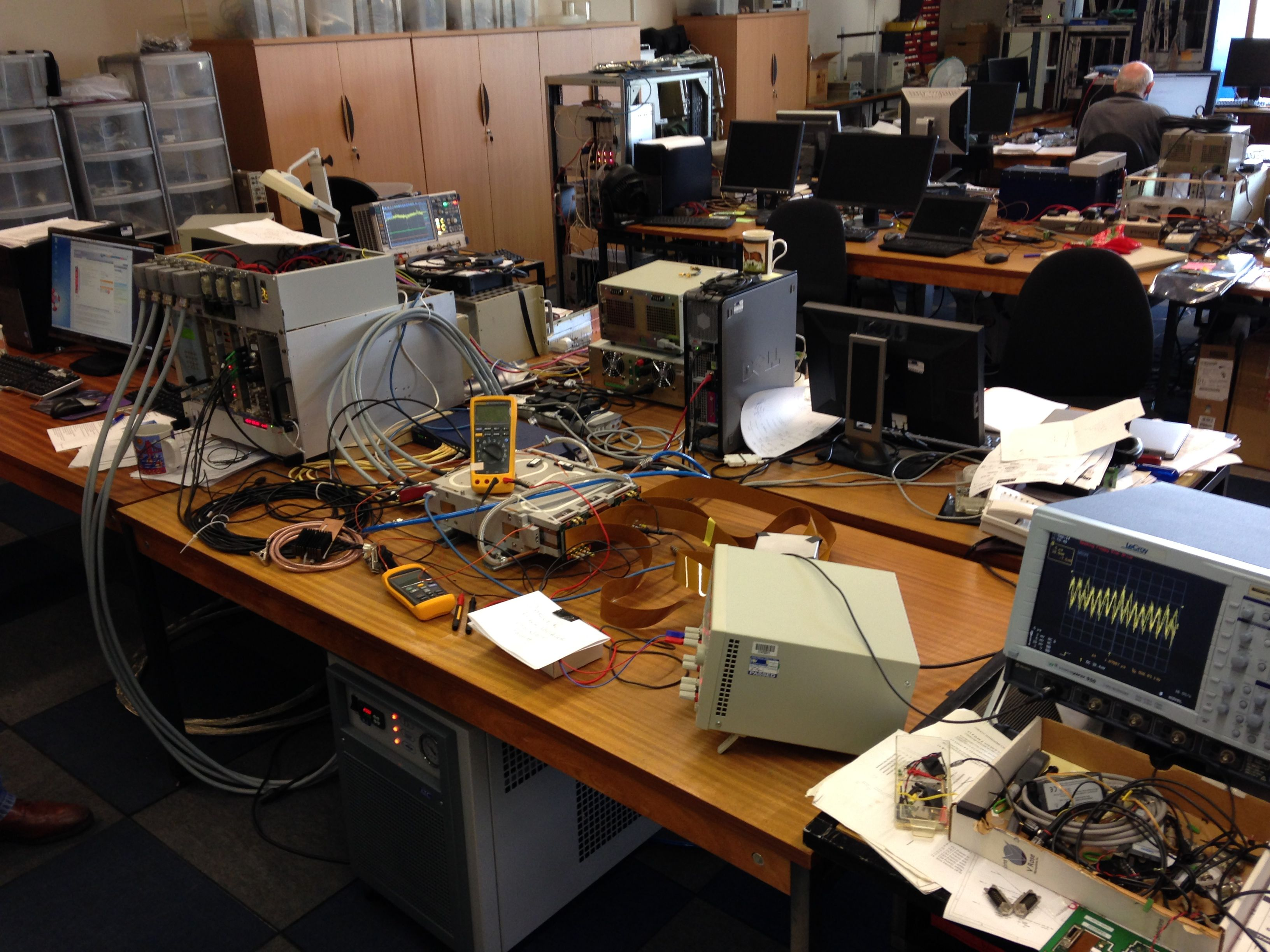
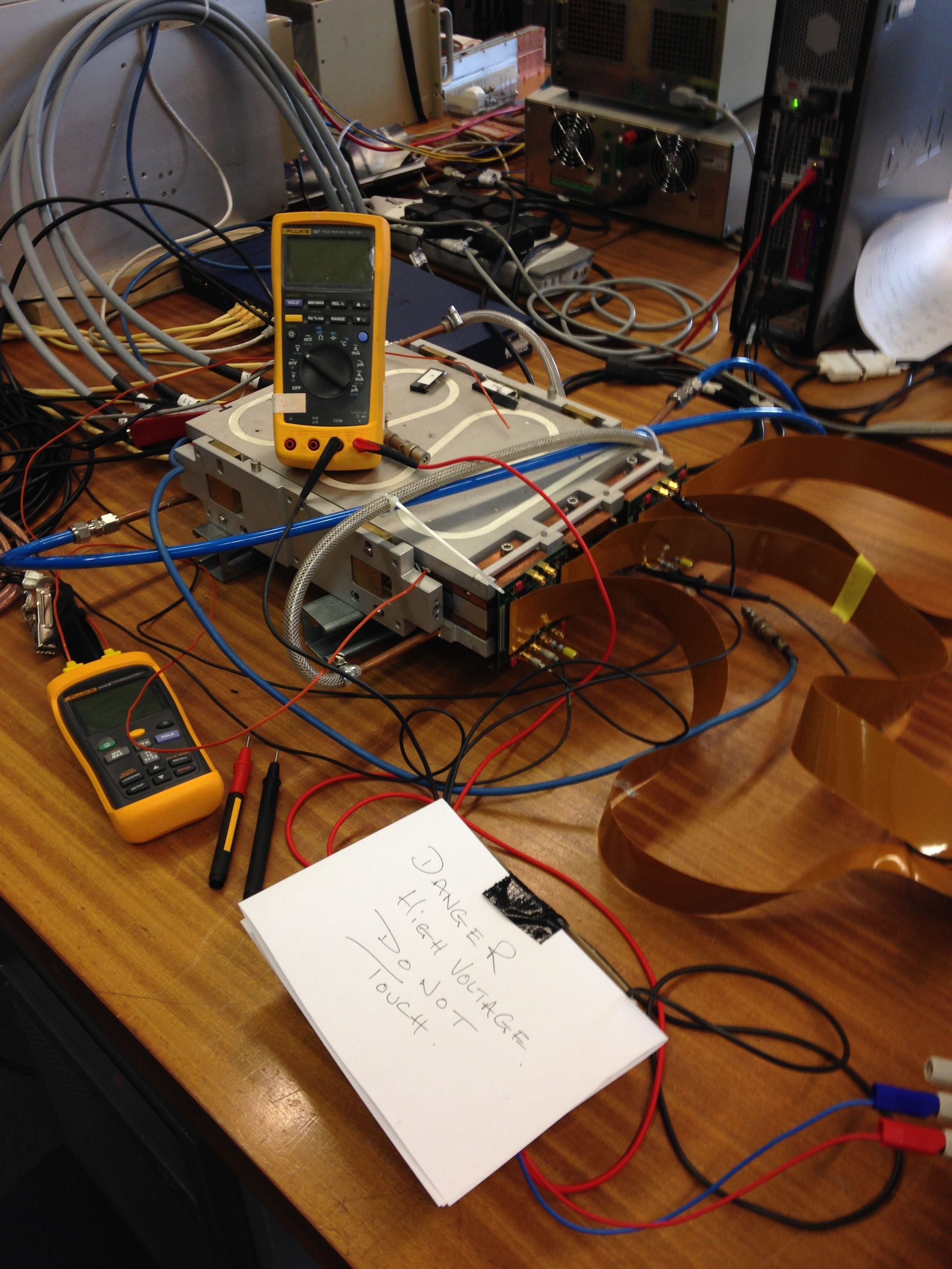
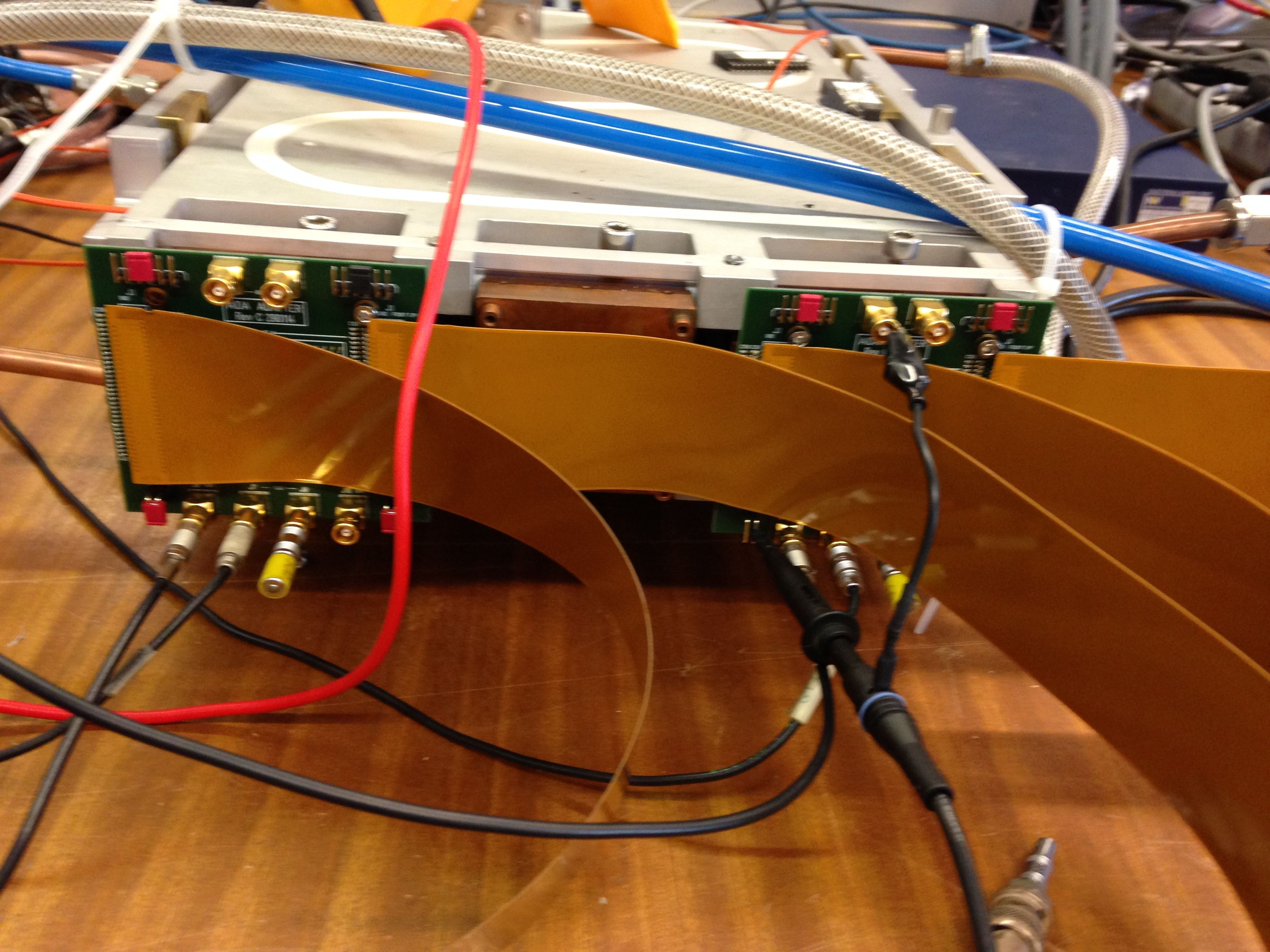
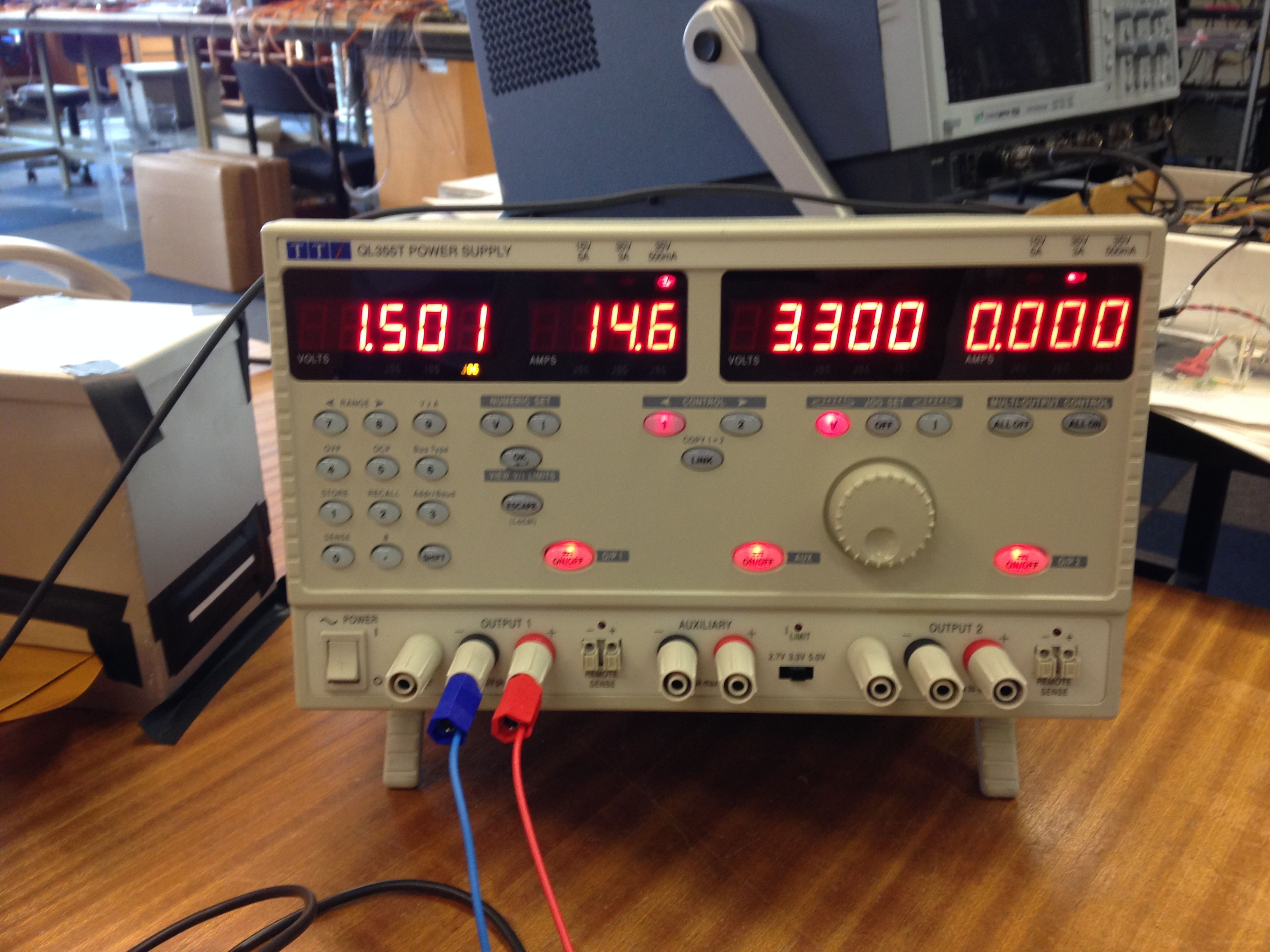
Tom Davinson and photos by Patrick | AIDA Tests at STFC DL - PCS, SLT, TD |
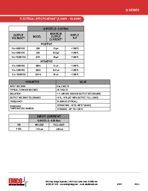
Changes from configuration described by Elog entry https://elog.ph.ed.ac.uk/AIDA/3
are as follows:


HV

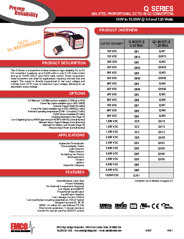
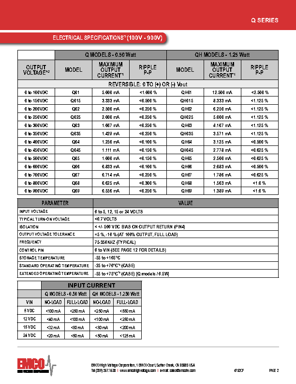
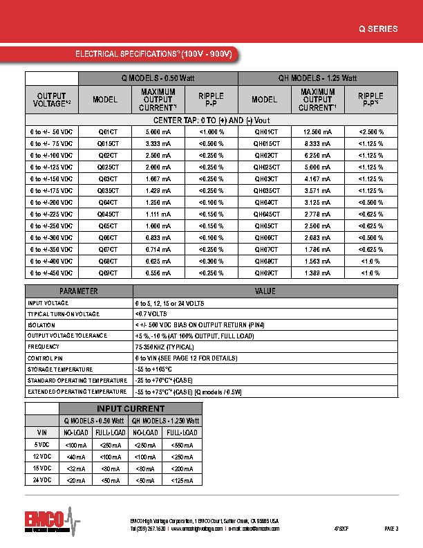
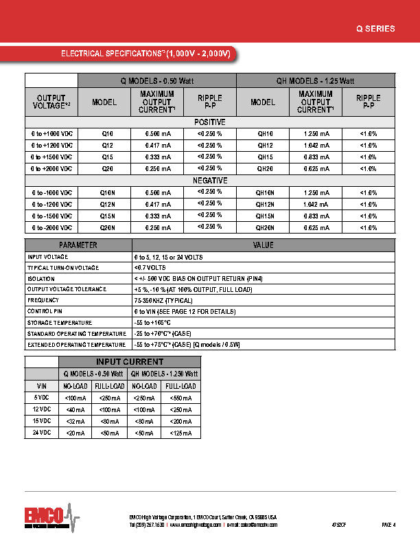
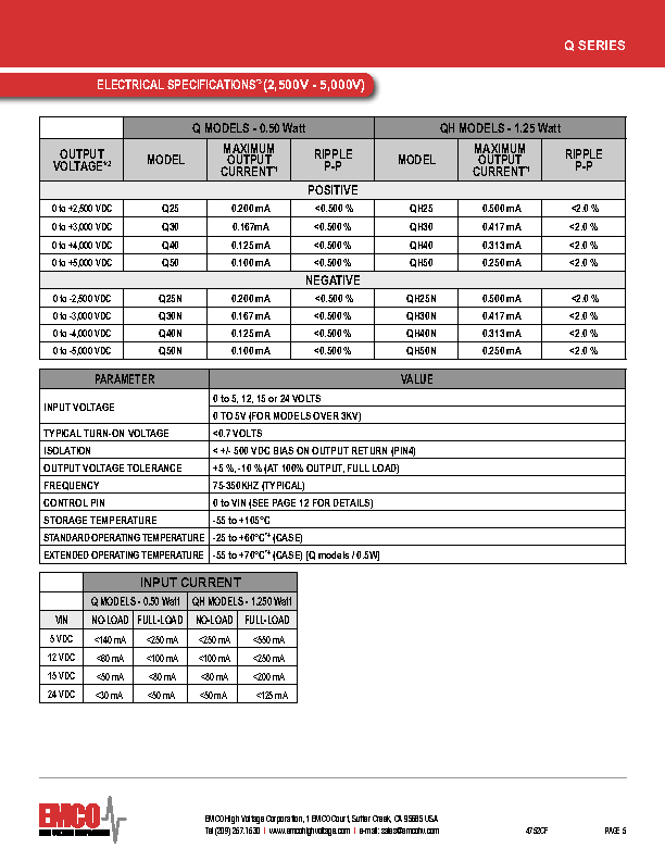
Emco Q05-5 ISOLATED, PROPORTIONAL DC TO HV DC CONVERTER

Input TTi QL355T set +1.5V, Emco Q05-5 output +194.6V

Output RC filter 1uF x 1MOhm

i.e. a filtered, floating high voltage detector bias supply
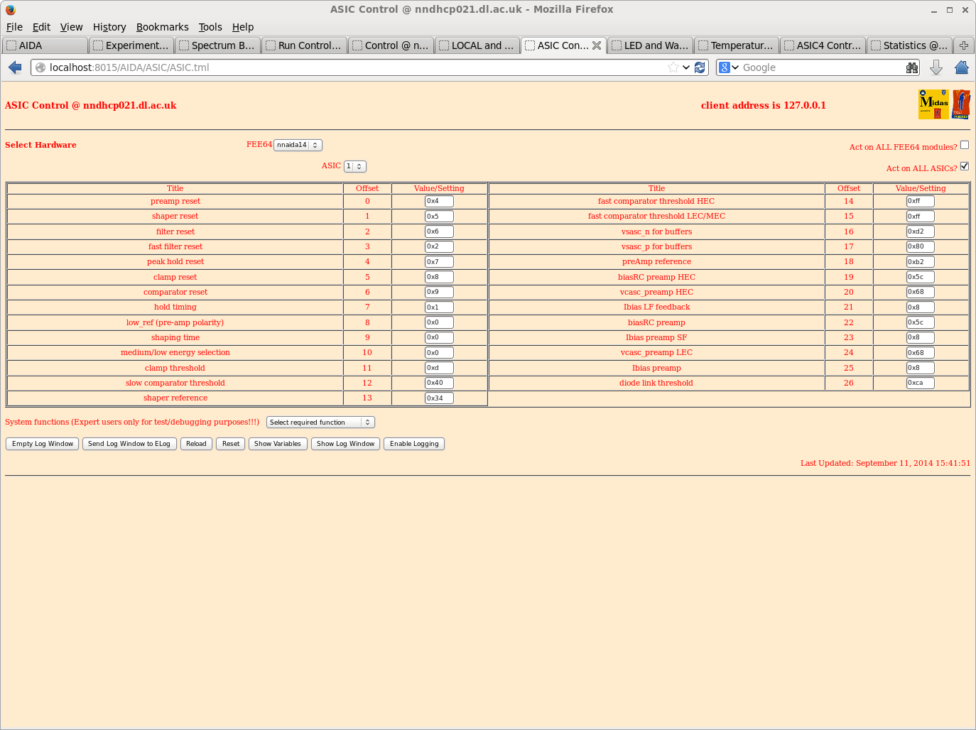
cf. NIM-bin grounded Silena 7710 Quad Bias used previously


ASIC Adaptor PCB

nnaida11 & nnaida12 LK 3 & 7
nnaida13 & nnaida13 LK 1, 3, 5, & 7

HV + -> nnaida11 & nnaida12
HV - -> nnaida13 & nnaida14
DSSSD grounded locally at nnaida12 & nnaida13 adaptor PCBs
by ground links LK 1 & 5 (cf. Silena 7710 Quad Bias Supply
used previously).


ASIC settings

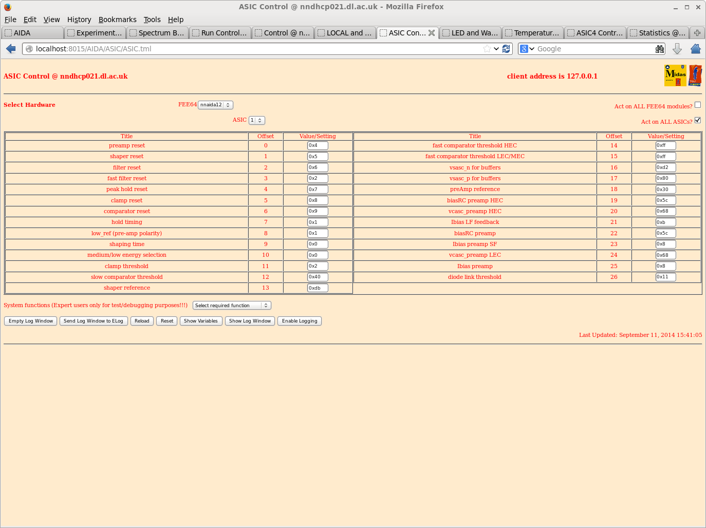
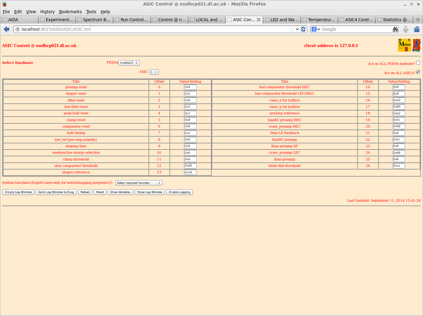
Default ASIC settings (see attachments 1-4)


Observe stable operation of both positive and negative polarity
FEE64s using default ASIC parameters and a floating HV detector
bias supply


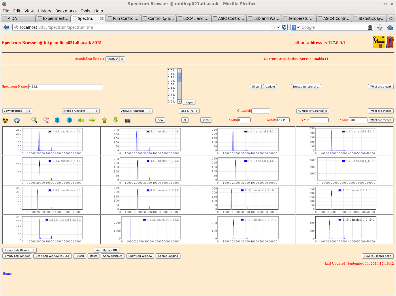
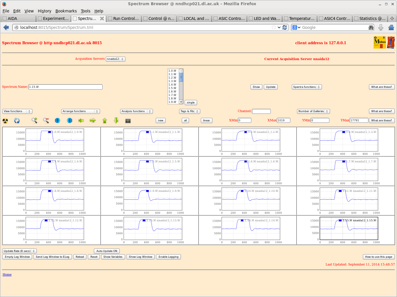
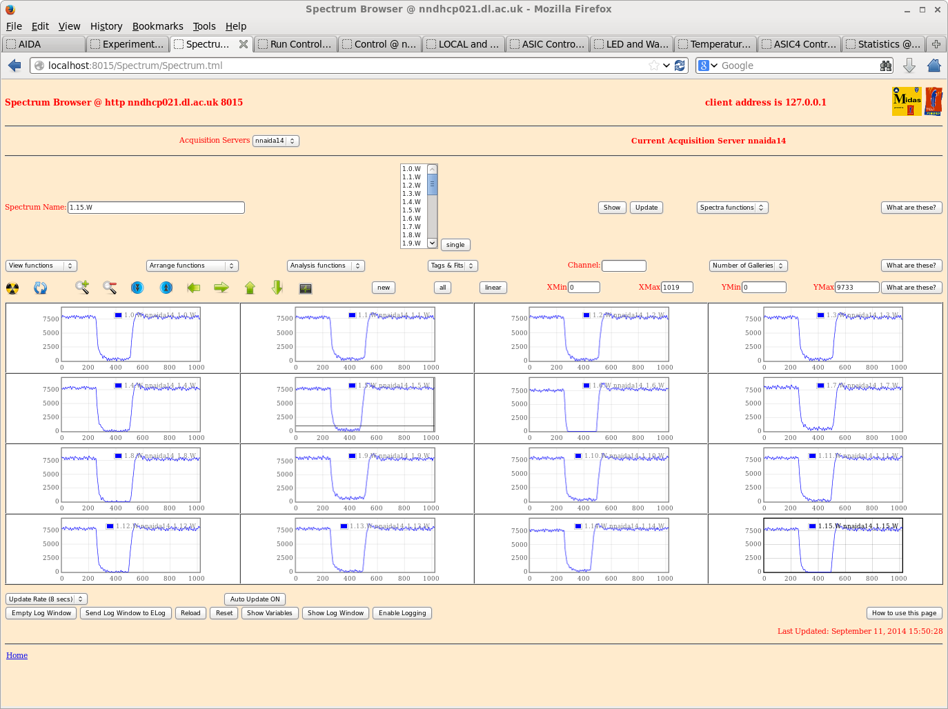
Attachments
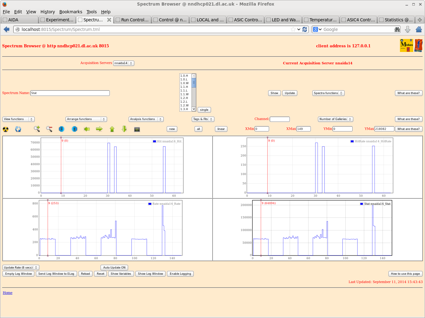
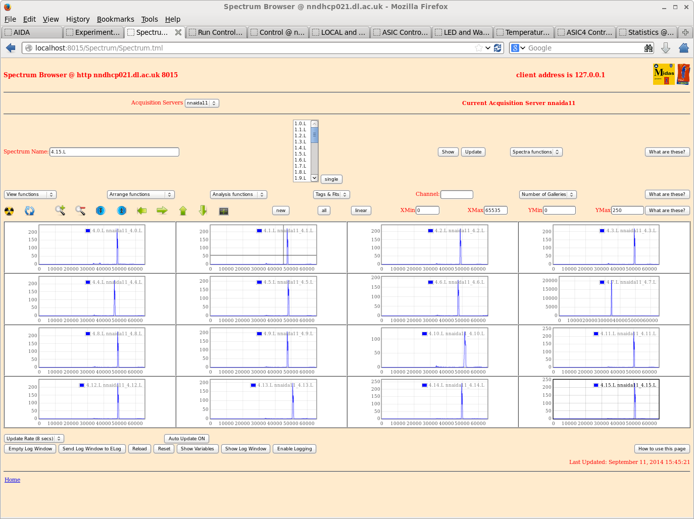
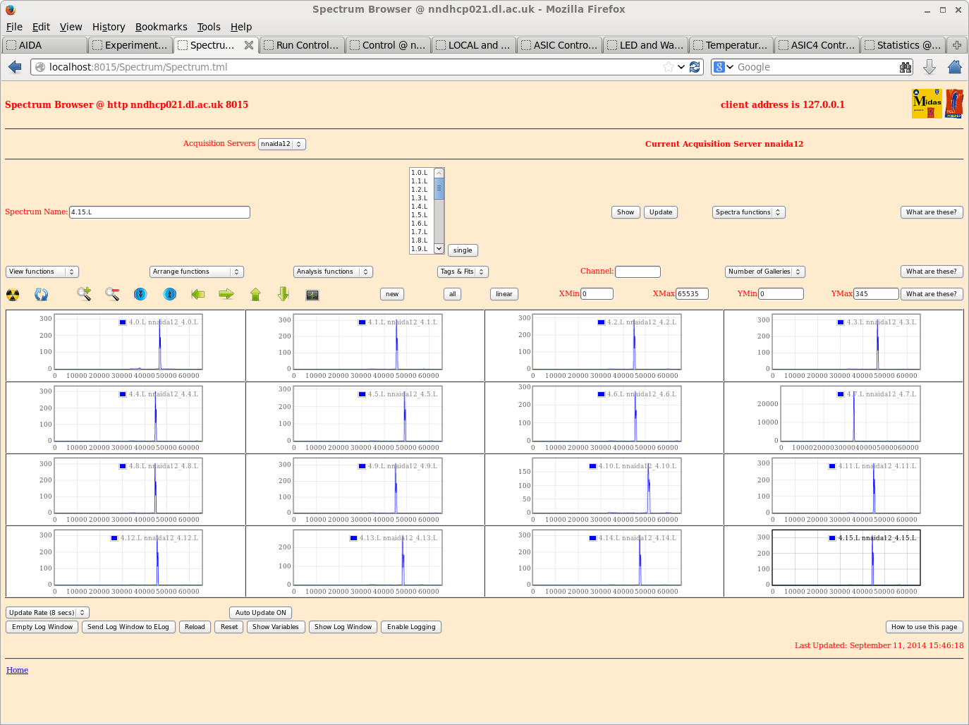
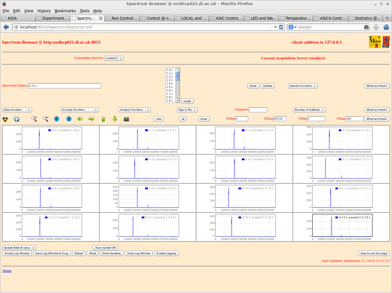
1-4 nnaida11, 12, 13, & 14 ASIC settings
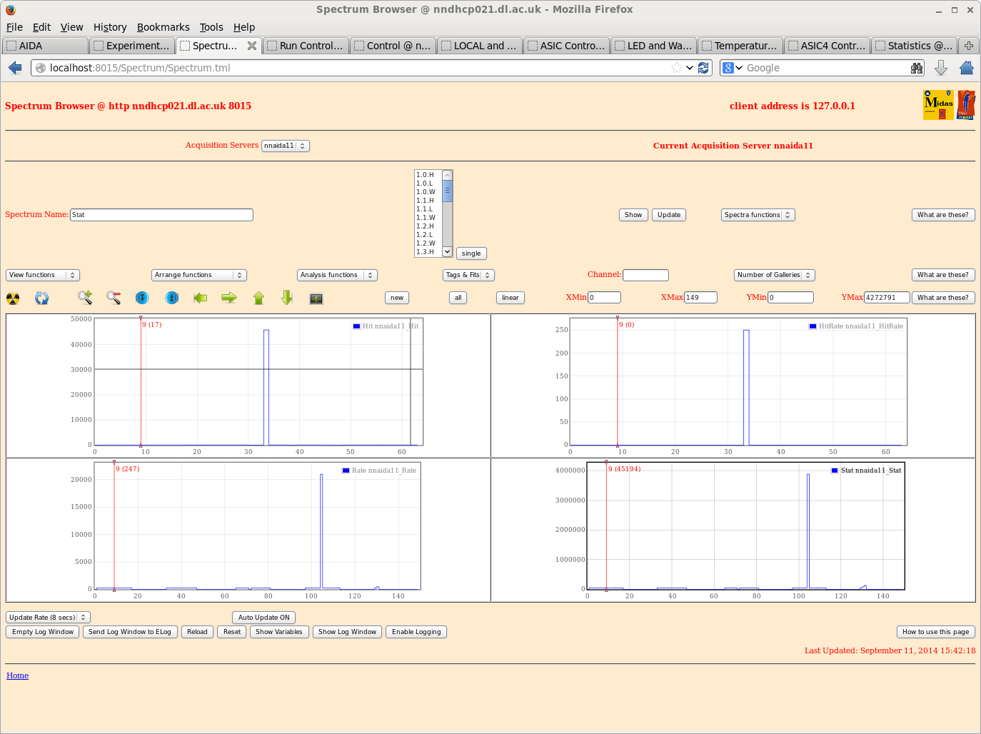
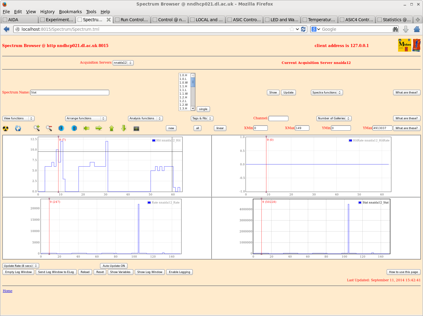
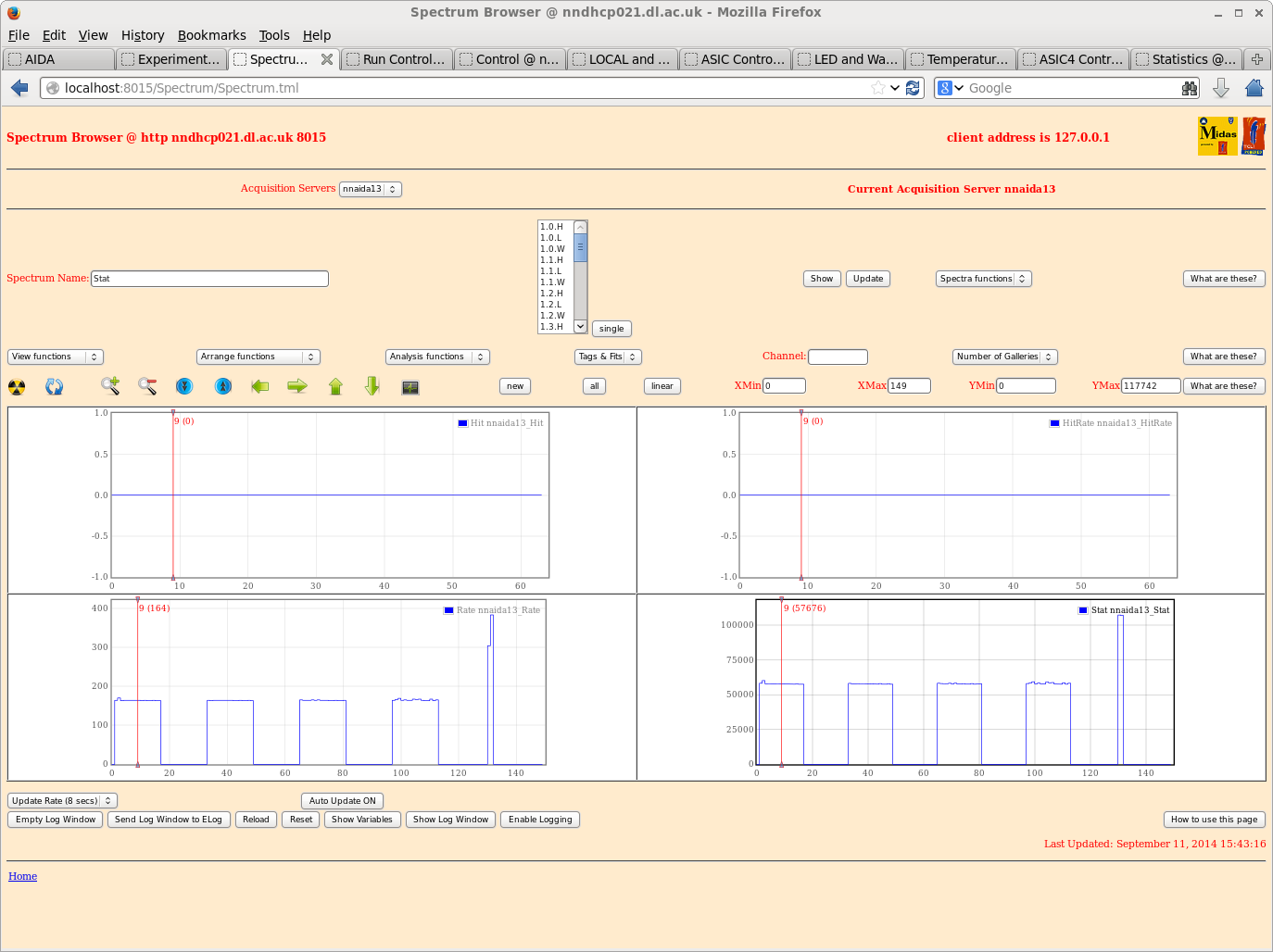
5-8 nnaida11, 12, 13, & 14 hit/rate patterns
9-12 nnaida11, 12, 13, & 14 ASIC # 4 ADC spectra
13 nnaida12 ASIC # 1 waveforms
14 nnaida14 ASIC # 1 waveforms
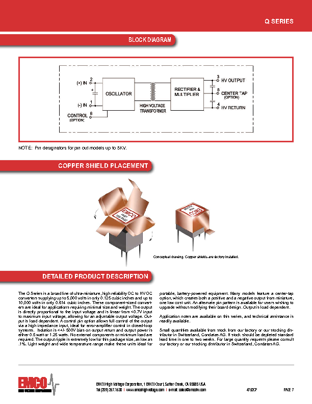
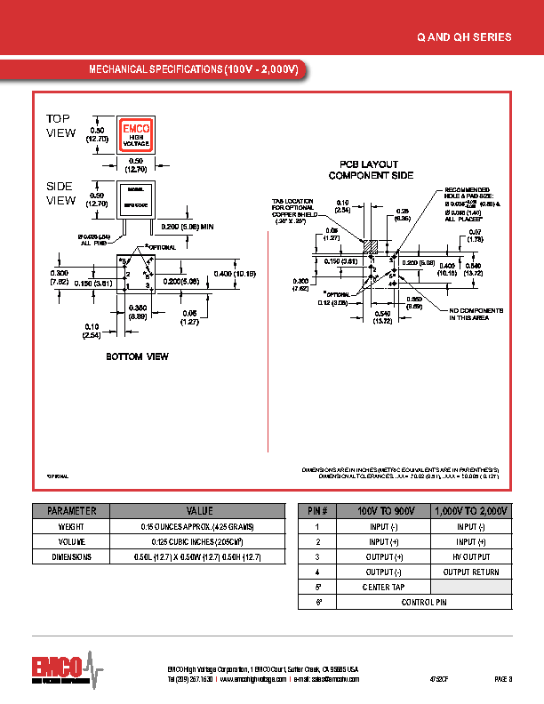
15 Emco Q-series catalogue |
| Attachment 1: 20.png
|

|
| Attachment 2: 21.png
|
|
| Attachment 3: 22.png
|
|
| Attachment 4: 23.png
|
|
| Attachment 5: 24.png
|
|
| Attachment 6: 25.png
|
|
| Attachment 7: 26.png
|
|
| Attachment 8: 27.png
|
|
| Attachment 9: 28.png
|
|
| Attachment 10: 29.png
|
|
| Attachment 11: 30.png
|
|
| Attachment 12: 31.png
|
|
| Attachment 13: 32.png
|
|
| Attachment 14: 33.png
|
|
| Attachment 15: qseries.pdf
|
|
| Attachment 16: IMG_0760.jpg
|
|
| Attachment 17: IMG_0761.jpg
|
|
| Attachment 18: IMG_0762.jpg
|
|
| Attachment 19: IMG_0763.jpg
|
|
|
3
|
Thu Sep 11 10:16:57 2014 |
Tom Davinson | AIDA Tests at STFC DL - PCS, SLT, TD |
MSL type BB18-1000 2998-22 bias +200V I_L +3.27uA

BNC PB-5

amp 2.0V
atten x1
tau_d 1ms
freq 200Hz
pol - (output split via EG&G Ortec 433A to generate + polarity too)

PSU

TTi QL355TP  "-6V & +7V" output set @ -7V & +8V, @ FEE64 -6.7V & +7.3V
TTi QPX1200S "5V" output set @ +6.2V, @ FEE64 +5.3V
 'linearly regulated output' PSUs  connected via standard FEE64 PSU chassis

Adaptor

nnaida11 & nnaida12 - polarity input (n+n ohmic strips)
  MSL type BB18 adaptor PCB rev 180713 LK 3 & 7
nnaida13 & nnaida14 + polarity input (p+n junction strips)
  MSL type BB18 adaptor PCB rev 180713 LK 1, 3, 5 & 7

FEE64

Note nnaida11 has been modified to remove the 470 Ohm resistors
linking the buffered preamp outputs from the ASICs to the buffer
amplifiers at the sampling ADC inputs. This effectively reduces
to zero the switching current load on the buffered preamp outputs.

ASIC parameters

  standard *except* nnaida11 & nnaida12 preAmp reference 0x20 -> 0x90
  which will reduce linear output range by c. x2 but significantly stabilises
  negative polarity input ASICs

  varying nnaida11 & nnaida12 'Ibias Preamp SF' and 'Ibias Preamp' from 0x8 -> 0x0
  had marginal effect on stability and degraded ADC spectra

Typical pulser peak widths for nnaida11, 12 (ASICs #1-3) and nnaida13, 14 (ASICs #1-4)
c. 130-150ch FWHM.

Attachments

1-4 nnaida11, 12, 13, & 14 ASIC parameters
5-8 nnaida11, 12, 13, & 14 hit/rate patterns
9-12 nnaida11 ASICs # 1-4
13-16 nnaida12 ASICs # 1-4
17 nnaida13 ASIC # 4
18 nnaida14 ASIC # 4
19 nnaida11, 12, 13 & 14 'good events' statistics |
| Attachment 1: 15.png
|

|
| Attachment 2: 16.png
|

|
| Attachment 3: 17.png
|

|
| Attachment 4: 18.png
|

|
| Attachment 5: 11.png
|

|
| Attachment 6: 12.png
|

|
| Attachment 7: 13.png
|

|
| Attachment 8: 14.png
|

|
| Attachment 9: 5.png
|

|
| Attachment 10: 6.png
|

|
| Attachment 11: 7.png
|

|
| Attachment 12: 8.png
|

|
| Attachment 13: 1.png
|

|
| Attachment 14: 2.png
|

|
| Attachment 15: 3.png
|

|
| Attachment 16: 4.png
|

|
| Attachment 17: 9.png
|

|
| Attachment 18: 10.png
|

|
| Attachment 19: 19.png
|

|
|
2
|
Wed Sep 10 09:27:43 2014 |
Patrick | Elog appreciation |
This is very interesting. Look forward to many happy interactions. |
|
1
|
Wed Sep 10 08:42:03 2014 |
Tom Davinson | Welcome to the AIDA Elog |
The AIDA Elog is now operational and can be found at

https://elog.ph.ed.ac.uk/AIDA/ |