| ID |
Date |
Author |
Subject |
|
78
|
Tue Feb 18 14:39:26 2020 |
Thomas Chillery | Target Thicknesses |
Excel spreadsheet showing CH2 and natC target thicknesses attached |
| Attachment 1: Target_List.xls
|
|
77
|
Wed Sep 18 14:01:13 2019 |
Thomas Chillery | Logbook Spreadsheet |
See attached for the logbook |
| Attachment 1: 181123_Logbook.xls
|
|
76
|
Tue Dec 4 11:23:29 2018 |
Thomas Chillery | Chamber Dimensions |
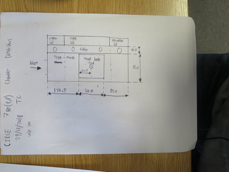
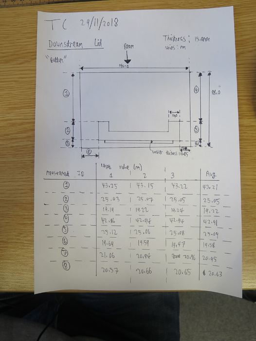
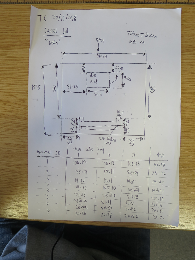
See attached pictures for measurements of the 7Be(p,p) chamber dimensions.
The target ladder center - Far S2 distance = 50 + 95 + 0.85 - (19.22+19.58)/2 = 126.45 mm |
| Attachment 1: IMG_3397.JPG
|
|
| Attachment 2: IMG_3398.JPG
|
|
| Attachment 3: IMG_3399.JPG
|
|
|
75
|
Tue Dec 4 09:40:31 2018 |
Thomas Chillery | Preliminary measurements of target activation using geiger counter |
On 29/11/2018 at 17:40 a rough measurement of the irradiated target activity was performed using a geiger counter.
The geiger counter was a calibrated Berthold LB124, which was placed a fixed 15mm distance from each target.
The calibration was such that 1cps = 37kBq.
The LB124 counter measured a background count of 0.5cps
| Target |
Irradiated with |
Berthold LB124 [cps] |
| CH2 XV |
7Li 4.0MeV |
0.0 |
| CH2 XVI |
7Li and 7Be 4.0MeV, 7Li 6.0MeV |
6.8 |
| CH2 XVIII |
7Li and 7Be 6.0MeV |
0.9 |
| CH2 XX |
Not used |
0.5 |
| natC III |
7Li and 7Be 3.0MeV, 4.0MeV, and 6.0MeV |
0.0 |
| CH2 XIX |
7Li and 7Be 3.0MeV |
11.5 |
|
|
74
|
Tue Dec 4 09:38:18 2018 |
Thomas Chillery | 181122 Electronics Map |
See attached for S2 electronics map, following channels from S2 outputs to ADC inputs
For the 19/11/2018 - 29/11/2018 beamtime only the Far S2 was in operation |
| Attachment 1: 181122_Electronics_Channel_Map.ods
|
| Attachment 2: 181122_Electronics_Channel_Map.xls
|
|
73
|
Mon Dec 3 19:04:20 2018 |
Thomas Chillery, Raffaele Buompane | End of beamtime - Items to be shipped back to Edinburgh |
To be shipped back to Edinburgh for repair:
|
Item
|
Quantity |
| ECL - NIM Convertor |
2 |
| Quad HV Supply |
1 |
| Quad TFA |
1 |
| SMC - SMC Cable |
1 |
| Central lid iris arm |
1 |
| Central lid - with iris |
1 |
| Diode mount |
1 |
| S2 2623-26 (505um) |
1 |
| PB-4 Pulser |
1 |
| BNC - SMC Bulkhead Connector (from close preamp box) |
1 |
| Lecroy 622 NIM module |
1 |
|
|
72
|
Mon Dec 3 18:55:31 2018 |
Thomas Chillery, Raffaele Buompane | End of beamtime - Cleanup |
On 29/11/2018:
Dismounted S2 2323-18 (496um), 12um mylar, diode, and diodes 0.9um mylar.
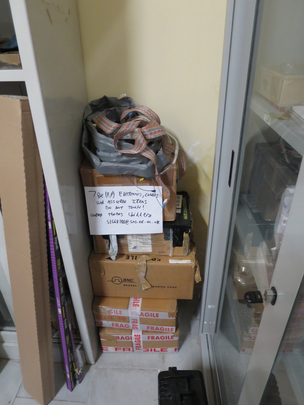
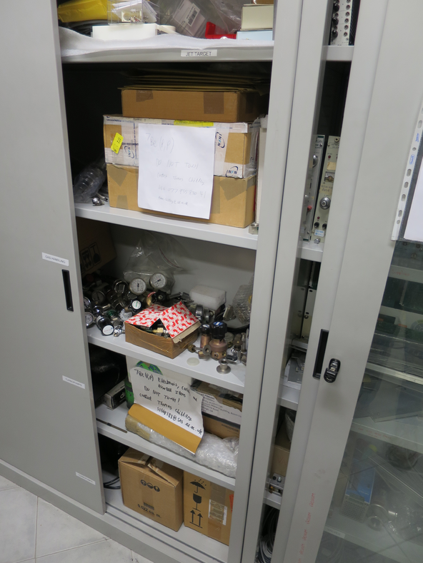
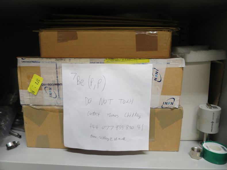
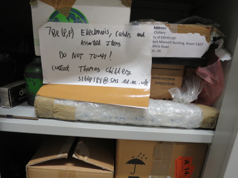
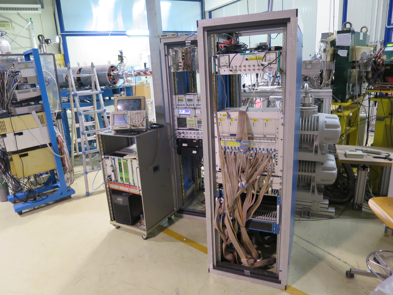
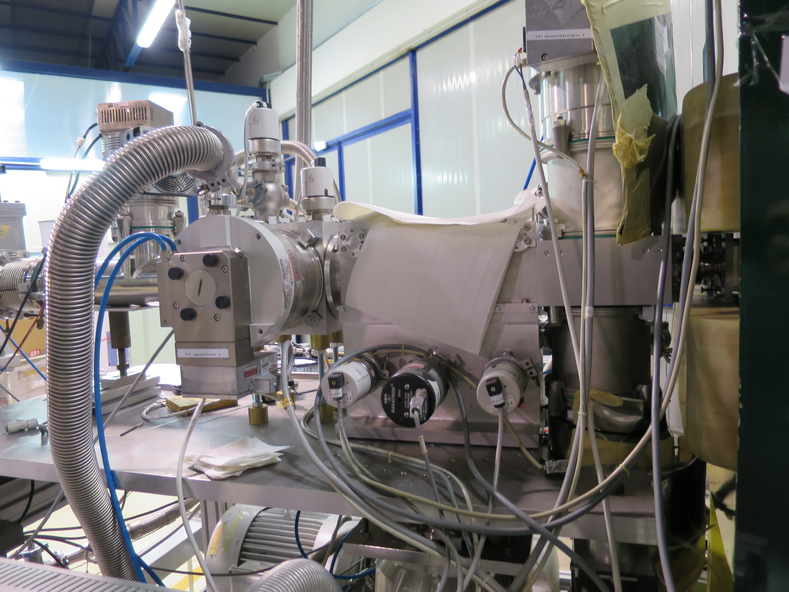
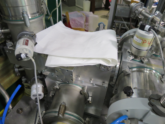
Performed general cleanup of lab. Boxed away cables and other parts. See attached pictures 1, 2, 3, and 4.
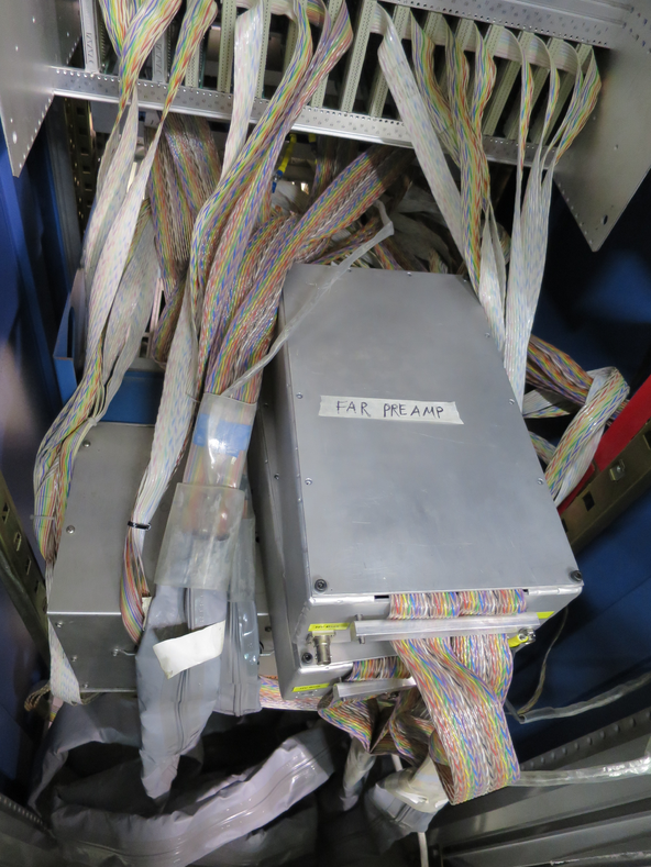
See attached picture 5, 6, 7, and 8 for status of electronics and target chamber at end of beamtime.
|
| Attachment 1: IMG_3381.JPG
|
|
| Attachment 2: IMG_3385.JPG
|
|
| Attachment 3: IMG_3383.JPG
|
|
| Attachment 4: IMG_3384.JPG
|
|
| Attachment 5: IMG_3386.JPG
|
|
| Attachment 6: IMG_3387.JPG
|
|
| Attachment 7: IMG_3388.JPG
|
|
| Attachment 8: IMG_3389.JPG
|
|
|
71
|
Mon Dec 3 18:45:17 2018 |
Thomas Chillery, Raffaele Buompane | End of beamtime - Module settings |
Diode Ortec 571 Amplifier Settings:
- Fine gain: 10 (0.5 ->1.5)
- Course gain: 50
- Shaping time: 0.5us
- BLR AUTO: ON
- NEG: ON (Instead of POS)
- OUT: ON (Instead of Delay)
- Internal fine gain: 1X
Diode quad TFA settings:
- No clipping cable attached
- Internal jumpers:
- W1: Invert
- W2 and W3: 200ns differentiation
- W4: T2 (not set to 50ns or OUT)
- W5: X5 course gain
Diode quad CFD settings:
- Threshold at minimum: -177.6mV
- Short delay cable attached (1ns)
- Internal jumpers:
- W1: no jumper
- W2: Top
- W3: no jumper
Oscilloscope used: Tektronix TDS 3054B
RAL Crate Configuration:
| RAL Crate Position (from left) |
RAL Module ID |
| 1 |
XV |
| 2 |
II |
| 3 |
XI |
| 4 |
IV |
| 5 |
V |
| 6 |
VI |
| 7 |
VII |
| 8 |
VIII |
| 9 |
X |
| 10 |
XII |
| 11 |
XIII |
| 12 |
R |
| 13 |
S |
| 14 |
Q |
| 15 |
U |
| 16 |
W |
|
|
70
|
Mon Dec 3 18:30:53 2018 |
Thomas Chillery, Raffaele Buompane | Calibration with alpha source - 12um mylar on Far S2 |
On 28/11/2018:
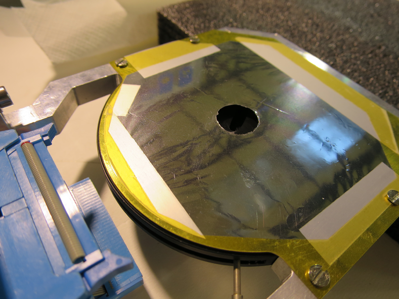
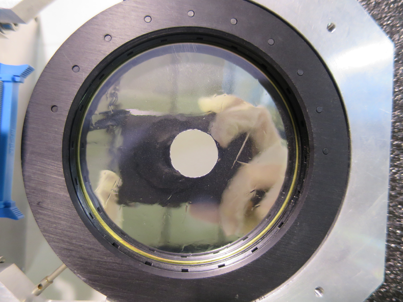
Mounted 12um mylar in front of far S2 - see attached pictures 1 and 2
In air: Far S2 biased to -130.0V, leak I = 1.61uA. Diode biased to -70.1V, leak I = 0.01uA -> 0.00uA. Rate meter ~ 4500Hz.
Detectors switched off
17:50 started Ecodry 1 and 2, started opening manual valve.
18:00 Manual valve fully opened, T1600 backing valve opened, Turbos switched on.
Once pressures ~ 1e-5mBar, far S2 bias = -130.0V, leak I = 1.59uA. Diode bias = -70.1V, leak I = 0.00uA.
18:08 Pressures (mBar):
- TPU1 = 3.0e-5
- TPU2 = 6.0e-5
- TPD1 = 5.2e-6
- TPD2 = 8.7e-6
- CHUP = Sensor Off
- CHDW = No Sensor
Run # 181128181421
- Run time: 1799s
- Pulser ON, as before
- Alpha source
- S2 mylar: 12um
- DT ~ 12%
Started overnight run:
Run # 181128184505
- Run time: 51706s
- Pulser ON, as before
- Alpha source
- S2 mylar: 12um
- DT ~ 8%
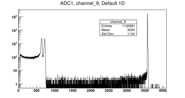
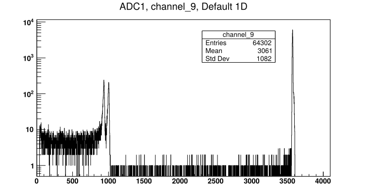
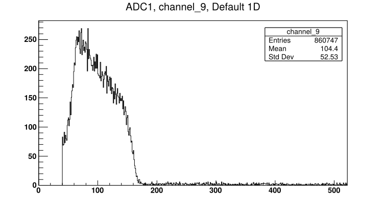
- See attached picture 3 for sample far S2 front strip spectrum
18:50 End of day check:
Far S2 bias = -130.0V, leak I = 1.60uA.
Diode bias = -70.1V, leak I = 0.00uA.
Pressures (mBar):
- TPU1 = 3.8e-6
- TPU2 = 1.2e-6
- TPD1 = 1.4e-6
- TPD2 = 1.6e-6
- CHUP = Sensor Off
- CHDW = No Sensor
On 29/11/2018: Alpha run stopped
9:05: Far S2 bias = -130.0V, leak I = 1.70uA. Diode bias = -70.1V, leak I = 0.00uA.
Detector biases and preamps off.
Pressures (mBar):
- TPU1 = 7.6e-7
- TPU2 = 3.5e-7
- TPD1 = 7.7e-7
- TPD2 = 7.3e-7
- CHUP = Sensor Off
- CHDW = No Sensor
Closed manual and T1600 backing valves. Stopped turbos. Stopped Ecodry 1 and 2.
Switched off Nim bin, RAL crate, and CAMAC crate
9:45 Opened venting valve |
| Attachment 1: IMG_3356.JPG
|
|
| Attachment 2: IMG_3363.JPG
|
|
| Attachment 3: 181128184505_ADC1_Ch9.png
|
|
|
69
|
Mon Dec 3 18:15:42 2018 |
Thomas Chillery, Raffaele Buompane | Calibration with alpha source - no mylar on Far S2 |
On 28/11/2018:
At 13:35: Far S2 bias = -130.0V, leak I = 1.55uA. Diode bias = -70.1V, leak I = 0.00uA.
Pressures (mBar):
- TPU1 = 3.3e-6
- TPU2 = 9,3e-7
- TPD1 = 1.2e-6
- TPD2 = 1.3e-6
- CHUP = Sensor Off
- CHDW = No Sensor
Switched off detectors, switched off pumps, closed manual and T1600 backing valves. Vented chamber.
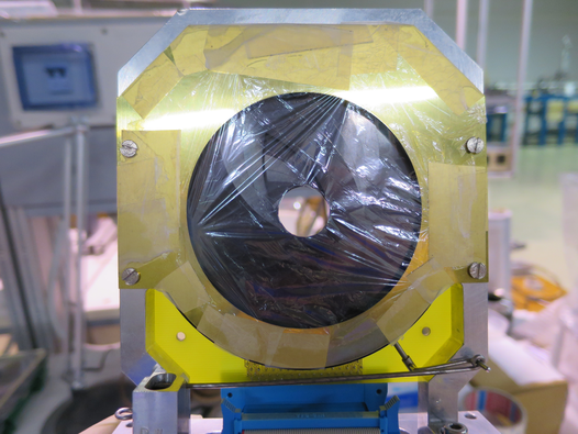
Removed 0.9um mylar from far S2 - see attached picture 1 for mylar pre-removal. Removed far iris arm from downstream lid -> set iris to open position. Replaced far iris actuator with blank flange.
Remounted far S2 and far preamp - preamp still draws correct currents.
In air: Far S2 bias = -130.0V, leak I = 1.65uA. Diode bias = -70.1V, leak I = 0.01uA. Rate meter ~ 5500Hz.
Detectors bias off.
15:05 Ecodry 1 and 2 on, started opening manual valve.
15:20 Manual valve fully opened, T1600 backing valve opened, turbos on
15:30 Pressures (mBar):
- TPU1 = 2.2e-5
- TPU2 = 4.4e-6
- TPD1 = 4.0e-6
- TPD2 = 4.7e-6
- CHUP = Sensor Off
- CHDW = No Sensor
Far S2 biased to 130.0V, leak I = 1.59uA. Diode biased to -70.1V, leak I = 0.00uA. Ratemeter ~ 7000Hz.
Run numbers 181128153642, 181128161647, and 181128161758 are all alpha calibration runs. However DAQ connection was lost before the first run was started so the run time is not recorded for these.
Run # 181128162552
- Run time: 1408s
- Pulser ON, as before
- Alpha source
- S2 mylar: NONE
- DT ~ 20%
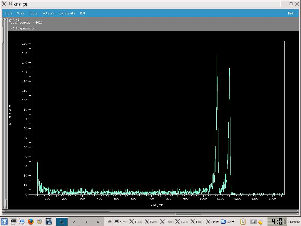
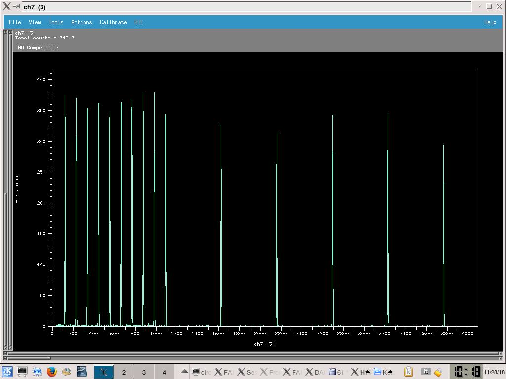
- See attached picture 2 for sample spectra from ADC2 Ch7 (ADC 3 in FAIR DAQ file browser)
16:45 Far S2 bias = -130.0V, leak I = 1.61uA. diode bias = -70.1V, leak I = 0.00uA.
Pressures (mBar):
- TPU1 = 2.8e-6
- TPU2 = 8.8e-7
- TPD1 = 1.2e-6
- TPD2 = 1.2e-6
- CHUP = Sensor Off
- CHDW = No Sensor
Switched off detectors, closed valves, turned off pumps, vented chamber.
|
| Attachment 1: IMG_3337.JPG
|
|
| Attachment 2: 182812_S2_Alpha_NoMylar.jpg
|
|
|
68
|
Mon Dec 3 17:59:48 2018 |
Thomas Chillery, Raffaele Buompane | Calibration with alpha source - 0.9um mylar on Far S2 |
On 28/11/2018:
After pulser walkthrough (see eLog entry #67)
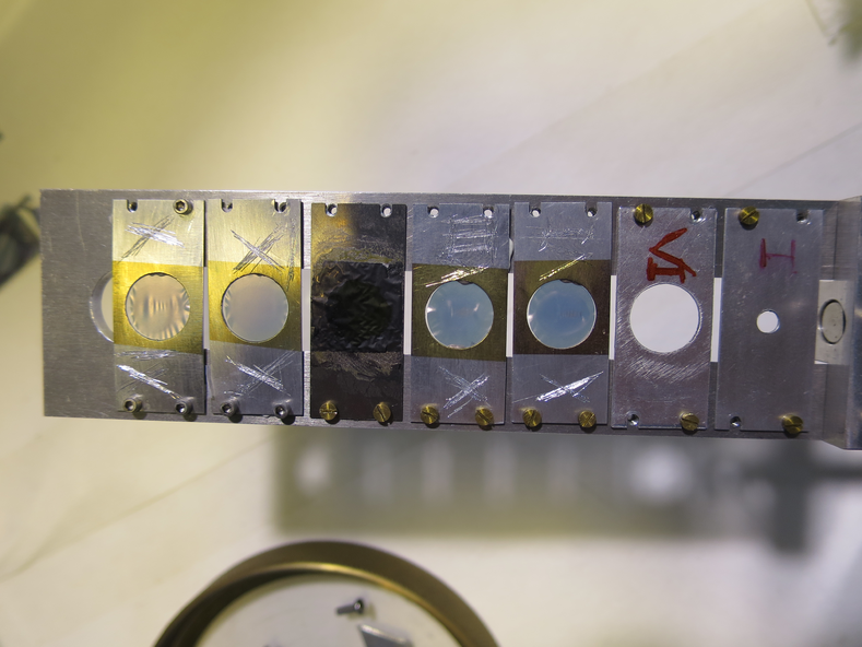
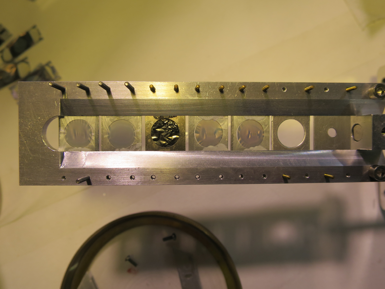
Dismounted targets from ladder - see picture 1 and 2 for upstream and downstream sides respectively
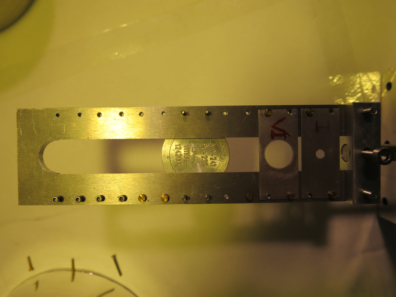
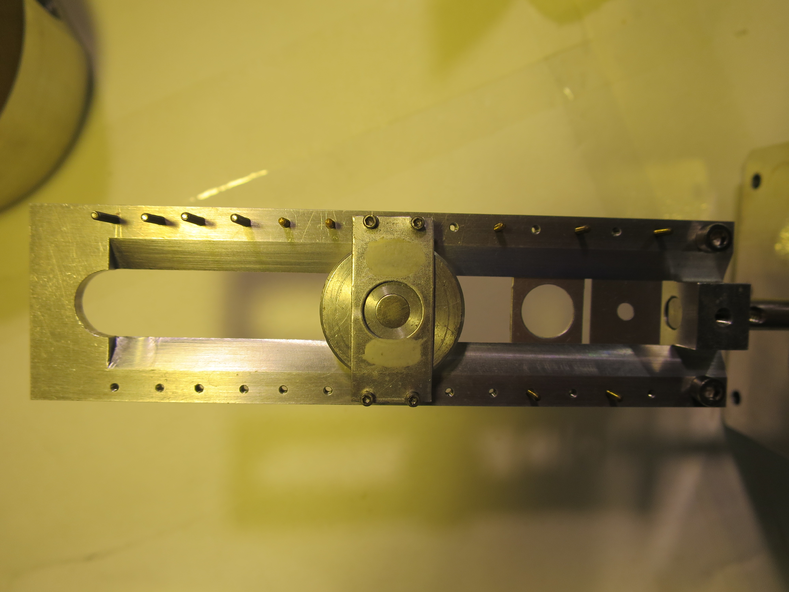
Mounted alpha source on ladder - see pictures 3 and 4 for upstream and downstream sides respectively
New target ladder configuration is now:
| Target Position |
Target |
| 1 |
Blank 3mm |
| 2 |
Blank 10mm |
| 3 |
Nothing |
| 4 |
Alpha-Source |
| 5 |
Nothing |
| 6 |
Nothing |
| 7 |
Nothing |
Dismounted thin CH2 target 50 - it was still attached to the collimator.
Remounted far S2 with 0.9um mylar, remounted far iris arm.
In air, pressures (mBar):
- TPU1 > 1000
- TPU2 > 1000
- TPD1 = 170 (above range)
- TPD2 = 73 (above range)
- CHUP = Sensor Off
- CHDW = No Sensor
Far S2 biased to -130.0V, leak I = 1.55uA. Diode biased to -70.1V, leak I = 0.01uA.
Ratemeter ~9200Hz.
Switched off detectors.
12:05 Ecodry 1 and 2 on. Started opening manual valve.
12:20 Manual valve opened fully, T1600 backing valve opened. Started turbos.
12:30 Pressures (mBar):
- TPU1 = 3.0e-5
- TPU2 = 5.1e-6
- TPD1 = 5.1e-6
- TPD2 = 7.5e-6
- CHUP = Sensor Off
- CHDW = No Sensor
Far S2 biased to -130.0V, leak I = 1.52uA. Diode biased to -70.1V, leak I = 0.01uA.
Rate meter ~ 7000Hz. Ladder set to position #4 - alpha source. Rate meter still ~ 7000Hz.
Run # 181128123940
- Run time: 3428s
- Pulser ON, as before
- Alpha-source
- S2 mylar: 0.9um
- DT ~ 22%
- See attached picture 5 for sample Far S2 front strip spectrum
|
| Attachment 1: IMG_3305.JPG
|
|
| Attachment 2: IMG_3307.JPG
|
|
| Attachment 3: IMG_3315.JPG
|
|
| Attachment 4: IMG_3313.JPG
|
|
| Attachment 5: 181128123940_ADC1_Ch9.png
|
|
|
67
|
Mon Dec 3 17:51:46 2018 |
Thomas Chillery, Raffaele Buompane | Pulser Walkthrough |
On 28/11/2018:
Performed pulser walkthrough, Run # 181128090835
- Run time: 1986s
- Pulser ON, amplitude changed
- Target: None
- Beam: None
- DT ~ 11%
- See attached picture 1 for sample pulser walkthrough spectrum, ADC 2 channel 3 (ADC 3 in DAQ file browser)
Pulser amplitudes swept through (measured amplitude checked after collecting pulser walkthrough to ensure no additional load was placed on pulser):
| Pulser Amplitude Setting |
Pulser Measured Amplitude (mV) |
| 70000 |
366 |
| 60000 |
318 |
| 50000 |
268 |
| 40000 |
206 |
| 30000 |
155 |
| 20000 |
102 |
| 18000 |
92.4 |
| 16000 |
82.8 |
| 14000 |
72.8 |
| 12000 |
62.4 |
| 10000 |
51.8 |
| 8000 |
42.0 |
| 6000 |
32.0 |
| 4000 |
22.0 |
| 2000 |
11.4 |
After walkthough pulser amplitude setting set back to 70000, all other settings left unchanged
Far S2 and diode biases switched off. Preamp power off. Line valve and FCC valve closed. Turbos off. Manual and T1600 backing valves closed. Ecodry 1 and 2 off. Waited for turbos to spin down.
By 10:20 turbos had finished spinning, vented chamber ready to mount alpha source. |
| Attachment 1: 182811_PulserWalkthrough.jpg
|
|
|
66
|
Mon Dec 3 17:40:51 2018 |
Thomas Chillery, Carlo Bruno, Raffaele Buompane | Lab background |
On 27/11/2018:
Run # 181127200709
- Run time: 46329s
- Pulser ON, as before
- No target
- No beam
- Lab background
- DT ~ 12%
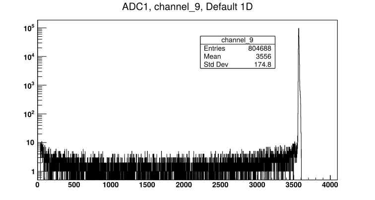
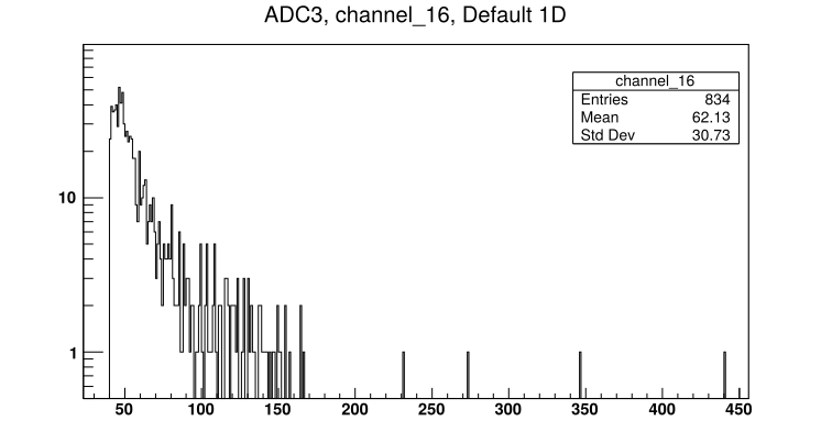
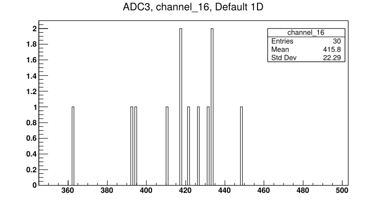
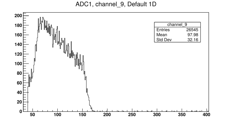
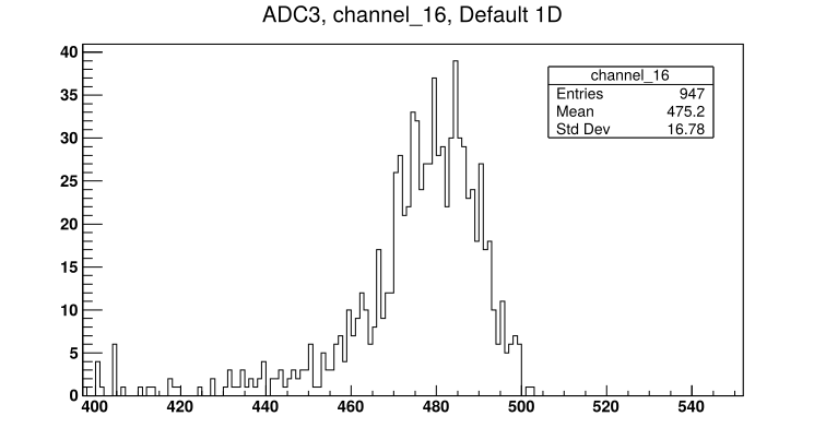
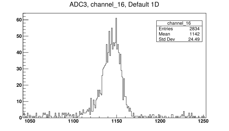
- See attached picture 1 for sample far S2 front strip spectrum. See attached picture 2 for diode spectrum.
At 20:00:
Far S2 bias = -130.0V, leak I = 1.52uA. Diode bias = -70.1V, leak I = 0.00uA. Preamps drawing correct current.
Pressures (mBar):
- TPU1 = 7.0e-6
- TPU2 = 1.9e-6
- TPD1 = 1.5e-6
- TPD2 = 1.7e-6
- CHUP = Sensor Off
- CHDW = No Sensor
Rate meter ~ 5000Hz
On 28/11/2018:
At 8:55 Far S2 bias = -130.0V, leak I = 1.67uA. Diode bias = -70.1V, leak I = 0.00uA.
Rate meter ~ 4100Hz
Pressures (mBar):
- TPU1 = 8.5e-7
- TPU2 = 6.3e-7
- TPD1 = 7.5e-7
- TPD2 = 6.5e-7
- CHUP = Sensor Off
- CHDW No Sensor
Stopped lab background run |
| Attachment 1: 181127200709_ADC1_Ch9.png
|
|
| Attachment 2: 181127200709_ADC3_Ch16.png
|
|
|
65
|
Mon Dec 3 17:34:38 2018 |
Thomas Chillery, Carlo Bruno, Raffaele Buompane | 6Li(p,p): Test measurement of 1.5MeV 6Li 1+ on thin CH2 50 |
On 27/11/2018:
After tuning beam (see previous eLog entry # 64)
Run #181127193908
- Run time: 1589s
- Pulser ON, as before
- Target: CH2 50
- Beam: 1.5MeV 6Li 1+
- See attached picture 1 for sample S2 front strip spectrum. See attached picture 2 for diode spectrum
|
| Attachment 1: 181127193908_ADC1_Ch9.png
|
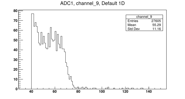
|
| Attachment 2: 181127193908_ADC3_Ch16.png
|
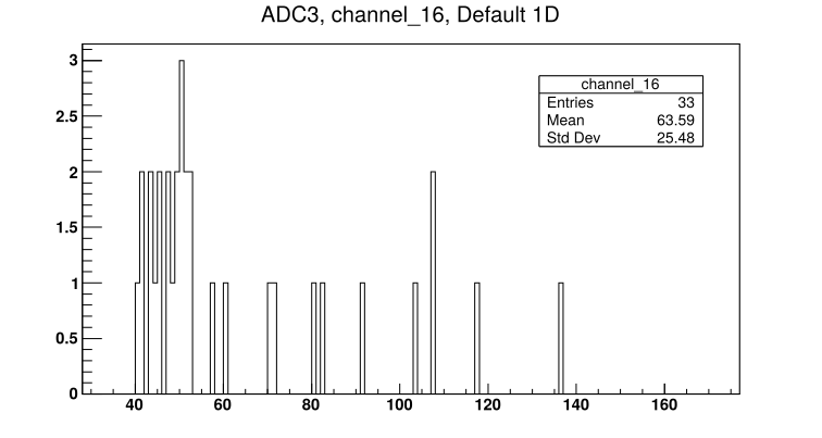
|
|
64
|
Mon Dec 3 17:02:48 2018 |
Thomas Chillery, Carlo Bruno, Lizeth Morales, Guiseppe Porzio, Raffaele Buompane | 6Li(p,p): Tuning 1.5MeV 6Li 1+ beam |
On 27/11/2018:
Started tuning for 1.5MeV 6Li 1+. Set ladder to position #2 - Blank 10mm. Far S2 iris closed.
Run # 181127151653
- Run time: N/A
- Pulser ON, as before
- Target: Blank 10mm
- Beam: 1.5MeV 6Li 1+
Moved ladder to position #5 - natC III
Run # 181127152055
- Run time: N/A
- Pulser ON, as before
- Target: natC III
- Beam: 1.5MeV 6Li 1+
- DAQ Crashed
Restarted FAIR DAQ
Run # 181127153422
- Run time: N/A
- Pulser ON, as before
- Target: natC III
- Beam: 1.5MeV 6Li 1+
- Run stopped incorrectly by user
Run # 181127153506
- Run time: 489s
- Pulser ON, as before
- Target: natC III
- Beam: 1.5MeV 6Li 1+
Run # 181127155040
- Run time: 187s
- Pulser ON, as above
- Target: natC III
- Beam: 1.5MeV 6Li 1+
Moved ladder to position #3 - CH2 XVI
Run # 181127155607
- Run time: 908s
- Pulser ON, as above
- Target: CH2 XVI
- Beam: 1.5MeV 6Li 1+
- DT ~ 15%
Struggling to see beam in diode for all of these past runs.
Opened iris to use far S2 as diagnostic tool - beam is stopped in thick CH2 targets so detector is safe even at its small angular coverage (~5 - 15 degrees)
Run # 181127161508
- Run time: 14s
- Pulser ON, as before
- Target: CH2 XVI
- Beam: 1.5MeV 6Li 1+
No high rate seen
Run # 181127161656
- Run time: 194s
- Pulser ON, as before
- Target: CH2 XVI
- Beam: 1.5MeV 6Li 1+
- DT ~ 12%
Still struggling to see beam on diode
Found lemo cable used for diode timing between CFD and Logic OR has exposed cabling -> replaced lemo. See attached picture 1 for old lemo.
Run # 181127163416
- Run time: 106s
- Pulser ON, as before
- Target: CH2 XVI
- Beam: 1.5MeV 6Li 1+
Far iris opened
Run # 181127163848
- Run time: N/A
- Pulser ON, as before
- Target: CH2 XVI
- Beam: 1.5MeV 6Li 1+
Realised we were making a mistake when looking at the DAQ spectra. We were looking at ADC 2 (labelled as 3 on DAQ file browser) channel 16 (an S2 back strip) when we should have been looking at ADC 3 (labelled as 4 on DAQ browser) channel 16 for the diode
Closed iris, checked beam current. Using 10mm aperture FCC = 1pA.
Opened iris, moved ladder to position #3 - CH2 XVI
Run # 181127164749
- Run time: 556s
- Pulser ON as before
- Target: CH2 XVI
- Beam: 1.5MeV 6Li 1+
Ready to mount thin CH2 target.
At 16:55: Far S2 bias = -130.0V, leak I = 1.75uA. Diode bias = -70.1V, leak I = 0.00uA.
Pressures (mBar):
- TPU1 = 9,2e-7
- TPU2 = 3.4e-7
- TPD1 = 6.4e-7
- TPD2 = 6.8e-7
- CHUP = Sensor Off
- CHDW = No Sensor
Switched off detector biases, switched off preamps. Closed FCC valve. Closed line valve. Turbos off. T1600 backing and manual valves closed. Ecodry 1 and 2 off.
Vented chamber. Mounted thin target CH2 50 ~ 50mm from Far S2 - see attached picture 2.
Left 0.9um mylar in front of far S2.
Remounted far S2 and far preamp. With detectors on in air trigger rate ~ 9kHz.
19:00 Ecodry 1 and 2 on. Started opening manual valve.
19:15 pressures below 10 mBar, manual valve fully opened. T1600 backing valve opened. Turbos on.
19:25 Pressures (mBar):
- TPU1 = 3.2e-5
- TPU2 = 8.1e-6
- TPD1 = 6.0e-6
- TPD2 = 8.3e-6
- CHUP = Sensor Off
- CHDW = No Sensor
Far S2 biased to - 130.0V, leak I = 1.52uA. Diode biased to -70.1V, leak I = 0.00uA.
Closed iris, set ladder to position #2 - blank 10mm
See 1 -> 2 pA beam on FCC, opened iris ready for measurement. |
| Attachment 1: IMG_3285.JPG
|
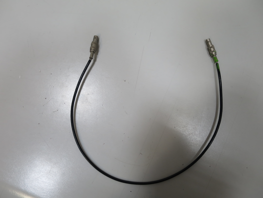
|
| Attachment 2: IMG_3292.JPG
|
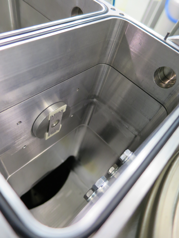
|
|
63
|
Mon Dec 3 16:47:40 2018 |
Thomas Chillery, Carlo Bruno, Lizeth Morales | Finishing 3.0MeV 7Be measurements with CH2 XIX and natC III |
On 27/11/2018:
At 8:40 Far S2 bias = -130.0V, leak I = 1.74uA. Diode bias = -70.1V, leak I = 0.00uA.
Pressures (mBar):
- TPU1 = 8.3e-7
- TPU2 = 3.4e-7
- TPD1 = 6.5e-7
- TPD2 = 6.5e-7
- CHUP = Sensor Off
- CHDW = No Sensor
Preamps still drawing necessary currents.
Stopped overnight run of 3.0MeV 7Be 2+ on CH2 XIX
Checked beam current: FC4 = 2pA.
Moved ladder to position #5 - natC III
Run # 181127085408
- Run time: 627s
- Pulser ON, as before
- Target: natC III
- Beam: 3.0MeV 7Be 2+
- DT ~ 23%
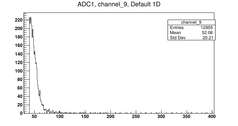
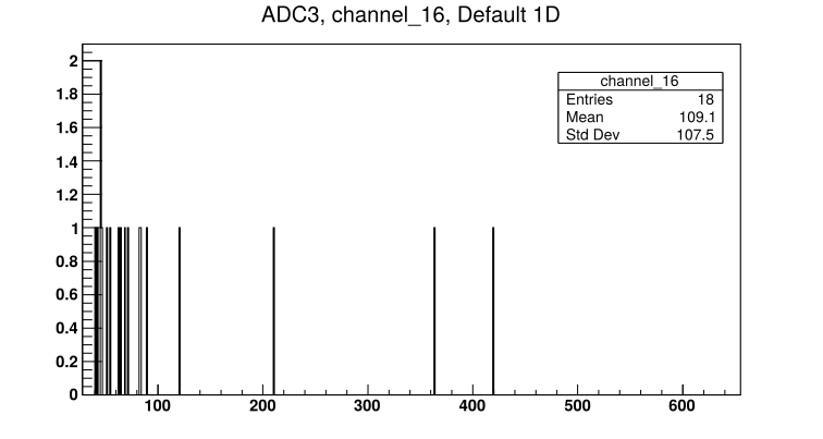
- See attached picture 1 for sample S2 front strip spectrum. See attached picture 2 for diode spectrum.
Moved ladder to position #2 - 10mm aperture
Run # 181127090808
- Run time: 601s
- Pulser ON, as before
- Target: Blank 10mm aperture
- Beam: 3.0MeV 7Be 2+
- DT ~ 10%
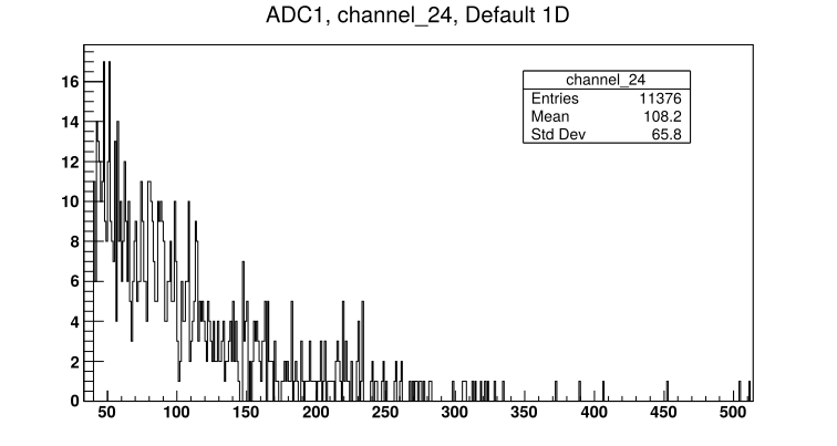
- See attached picture 3 for Far S2 innermost strip spectrum.
Moved ladder to position #7 - CH2 XIX
Run # 181127092128
- Run time: 663s
- Pulser ON, as before
- Target: CH2 XIX
- Beam: 3.0MeV 7Be 2+
- DT ~ 10%
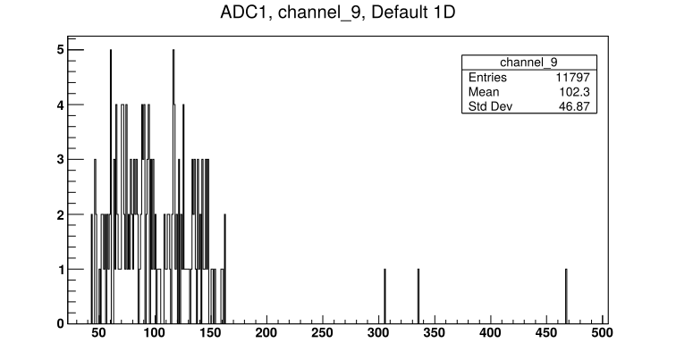
- See attached picture 4 for sample S2 front strip spectrum. See attached picture 5 for diode spectrum.
* End of 7Be beam * |
| Attachment 1: 181127085408_ADC1_Ch9.png
|
|
| Attachment 2: 181127085408_ADC3_Ch16.png
|
|
| Attachment 3: 181127090808_ADC1_24.png
|
|
| Attachment 4: 181127092128_ADC1_Ch9.png
|
|
| Attachment 5: 181127092128_ADC3_Ch16.png
|
|
|
62
|
Mon Dec 3 16:39:42 2018 |
Thomas Chillery, Carlo Bruno, Tom Davinson, Raffaele Buompane | 3.0MeV 7Be on CH2 XIX |
On 26/11/2018:
Tuned beam for 3.0MeV 7Be 2+. Far S2 iris was closed during tuning.
After tuning, using 10mm aperture FCC = 5pA, using 3mm aperture FCC = 4pA.
Set ladder to position #7 - CH2 XIX
Run # 181126190248
- Run time: 1298s
- Pulser ON, as before
- Target: CH2 XIX
- Beam: 3.0MeV 7Be 2+
Left beam running and data collecting overnight
Run # 181126192446
- Run time: 47915s
- Pulser ON, as before
- Target: CH2 XIX
- Beam: 3.0MeV 7Be 2+
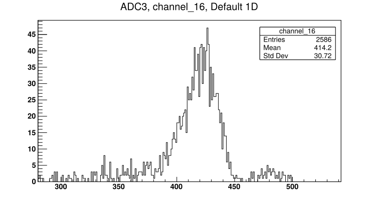
- See attached picture 1 for sample S2 front strip spectrum. See attached picture 2 for diode spectrum.
|
| Attachment 1: 181126192446_ADC1_Ch9.png
|
|
| Attachment 2: 181126192446_ADC3_Ch16.png
|
|
|
61
|
Mon Dec 3 16:17:29 2018 |
Thomas Chillery, Carlo Bruno, Tom Davinson, Raffaele Buompane, David Rapagni | 3.0MeV 7Li on CH2 XIX and natC III |
On 26/11/2018, after changing the far S2 mylar foil (see previous eLog entry #60):
Checked pulser frequency on oscilloscope: 19.31Hz
Began tuning 3MeV 7Li 2+.
After tuning, FC4 = 1nA. Using 10mm aperture FCC = 313pA. Using 3mm aperture FCC = 250pA.
Ladder set to position #7 - fresh C2 XIX target. Far S2 iris opened.
Run # 181126162248
- Run time: 753s
- Pulser ON, as before
- Target: CH2 XIX
- Beam: 3.0MeV 7Li 2+
- DT ~ 18%
Set ladder to position #5 - natC III
Note: now saving to /Local_Parts/PartODF/
Run # 181126163853
- Run time: 73s
- Pulser ON, as before
- Target: natC III
- Beam: 3.0MeV 7Li 2+
- DT ~ 20%
- Observe 7Li passing through target
Moved ladder to position #2 - blank 10mm aperture
Run # 181126164509
- Run time: 67s
- Pulser ON, as before
- Target: Blank 10mm
- Beam: 3.0MeV 7Li 2+
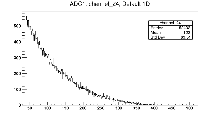
Still see scattered beam at low S2 strips #'s - see attached picture 1 for spectrum of the innermost S2 strip.
Performed further beam tuning to improve transmission.
After tuning: Using 10mm aperture FCC = 415pA (280 - 420pA). Using 3mm aperture FCC = 290pA.
Moved ladder to position #3 - CH2 XVI. Bombarded target with 3.0MeV 7Li 2+ and checked rate histogram on FAIR DAQ. ADC1 CH24 didn't show higher rates compared to other channels (eg ADC 1 CH10)
Moved ladder to position #7 - CH2 XIX
Run # 181126183711
- Run time: 616s
- Pulser ON, as before
- Target: CH2 XIX
- Beam: 3.0MeV 7Li 2+
- DT ~ 14%
- See attached picture 2 for sample S2 front strip spectrum. See attached picture 3 for diode spectrum.
|
| Attachment 1: 181126164509_ADC1_24.png
|
|
| Attachment 2: 181126183711_ADC1_Ch9.png
|
|
| Attachment 3: 181126183711_ADC3_Ch16.png
|
|
|
60
|
Mon Dec 3 15:51:11 2018 |
Thomas Chillery, Carlo Bruno, Tom Davinson, David Rapagni | Changing far S2 protective mylar foil, preparing for 3.0MeV 7Li and 7Be |
On 26/11/2018, after 6.0MeV 7Be and 7Li beam measurements:
At 11:15:
Far S2 bias = -130.0V, leak I = 1.60uA. Diode bias = -70.1V, leak I = 0.00uA.
Pressures (mBar):
- TPU1 = 8.5e-7
- TPU2 = 3.1e-7
- TPD1 = 6.2e-7
- TPD2 = 6.3e-7
- CHUP = Sensor Off
- CHDW = No Sensor
Detectors and preamps switched off. Turbos off. Line valve closed. Manual and T1600 backing valves closed. Ecodry 1 and 2 off.
Waited for turbos to spin down.
Opened vent valve at Turbo Entrance 3. The automatic FCC valve immediately closed -> interlock tripped downstream of chamber and stopped turbo at FCC.
With FCC valve closed (allowing the chamber to continue venting) we restarted turbo at FCC -> spun up to operating 1000 Hz.
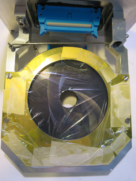
Once chamber finished venting, the far S2 was removed and its 12um mylar was replaced with 0.9um mylar ready for beam measurements at Elab = 3MeV. See picture 1 for 0.9um mylar mounted in front of far S2.
Far S2 remounted with far iris arm. Far S2 preamp remounted.
Preamp power on, currents drawn are good. Far S2 biased to -130.0V, leak I = 1.53uA. Diode biased to -70V, leak I = 0.00uA.
Noise looked ok. Detector biases off.
12:50 Ecodry 1 and 2 on. Started opening manual valve.
13:05 manual valve opened fully. T1600 valve opened.
13:10 Turbos on, pressures reached ~9e-5 mBar
Far S2 bias = -130.0V, leak I = 1.48uA. Diode bias = -70.1V, leak I = 0.00uA.
Set new RAL thresholds whilst monitoring rate: (counting from left of RAL rack)
- RAL #1 and 2: 20mV
- RAL #3: 15mV
- RAL #4 and 5: 10mV
- RAL #6: 15mV
13:25 Pressures (mBar):
- TPU1 = 1.0e-5
- TPU2 = 2.8e-6
- TPD1 = 2.5e-6
- TPD2 = 3.3e-6
- CHUP = Sensor Off
- CHDW = No Sensor
|
| Attachment 1: IMG_3273.JPG
|
|
|
59
|
Mon Dec 3 12:57:54 2018 |
Thomas Chillery, Carlo Bruno, Tom Davinson, David Rapagni | Finishing 6.0MeV 7Be 2+ and 7Li 2+ beam runs |
On 26/11/2018:
The accelerator and chamber setup were still operating after the overnight run.
Far S2 bias = -130V, leak I = 1.59uA. Diode bias = -70.1V, leak I = 0.00uA.
8:35 pressures (mBar):
- TPU1 = 8.6e-7
- TPU2 = 3.1e-7
- TPD1 = 6.1e-7
- TPD2 = 6.3e-7
- CHUP = Sensor Off
- CHDW = No Sensor
Checking for beam-induced background, moved target ladder to position # 2 - blank 10mm aperture
Run # 181126084821
- Run time: 1204s
- Pulser ON, as before
- Target: Blank 10mm
- Beam: 6.0MeV 7Be 2+
Using blank 10mm frame FCC = 6pA
Stopped run - CSSM magnet was switched on halfway through. This this the magnet located immediately downstream of the chamber and we were worried about it affecting the noise. Switched off CSSM magnet.
Run # 181126090936
- Run time: 1239s
- Pulser ON, as before
- Target: Blank 10mm
- Beam: 6.0MeV 7Be 2+
- DT ~ 8%
Moved ladder to position #5 - natC III
Run # 181126093314
- Run time: 1416s
- Pulser ON, as before
- Target: natC III
- Beam: 6.0MeV 7Be 2+
- DT ~ 8%
Moved ladder to position #2 - blank 10mm aperture. Closed far S2 iris and switched beam to 6.0MeV 7Li 2+.
Using 10mm aperture FCC = 360pA. Using 3mm aperture FCC = 300pA.
Moved ladder to position #4 - CH2 XVIII. Opened Far S2 iris.
Run # 181126105357
- Run time: 1383s
- Pulser ON, 25Hz
- Target: CH2 XVIII
- Beam: 6.0MeV 7Li 2+
- DT ~ 12%
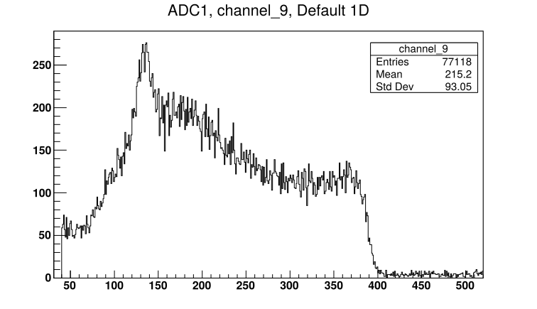
- See attached picture 1 for sample Far S2 front strip. See attached picture 2 for diode spectrum.
Ready to replace Far S2 12um mylar with 0.9um mylar protective foil |
| Attachment 1: 181126105357_ADC1_Ch9.png
|
|
| Attachment 2: 181126105357_ADC3_Ch16.png
|
|