| ID |
Date |
Author |
Subject |
|
Draft
|
Wed Jan 7 02:21:13 2026 |
BA, AA | Saturday 14 May |
| Quote: |
|
FEE64 module aida09 global clocks failed, 6
Clock status test result: Passed 13, Failed 1
Understand status as follows
Status bit 3 : firmware PLL that creates clocks from external clock not locked
Status bit 2 : always logic '1'
Status bit 1 : LMK3200(2) PLL and clock distribution chip not locked to external clock
Status bit 0 : LMK3200(1) PLL and clock distribution chip not locked to external clock
If all these bits are not set then the operation of the firmware is unreliable
FEE64 module aida02 failed
FEE64 module aida06 failed
FEE64 module aida09 failed
FEE64 module aida10 failed
FEE64 module aida13 failed
Calibration test result: Passed 9, Failed 5
If any modules fail calibration , check the clock status and open the FADC Align and Control browser page to rerun calibration for that module
White Rabbit error counter test result: Passed 14, Failed 0
Understand the status reports as follows:-
Status bit 3 : White Rabbit decoder detected an error in the received data
Status bit 2 : Firmware registered WR error, no reload of Timestamp
Status bit 0 : White Rabbit decoder reports uncertain of Timestamp information from WR
FPGA Timestamp error counter test result: Passed 14, Failed 0
If any of these counts are reported as in error
The ASIC readout system has detected a timeslip.
That is the timestamp read from the time FIFO is not younger than the last
|
|
|
745
|
Wed Nov 19 10:28:24 2025 |
JEL, JB | Analysis of AIDA from S100 experiment by JEL |
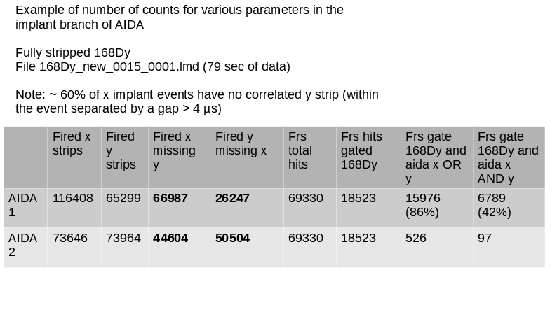
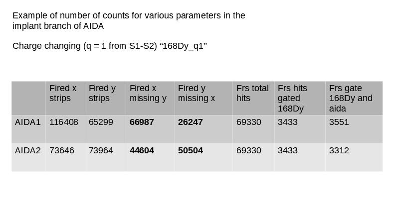
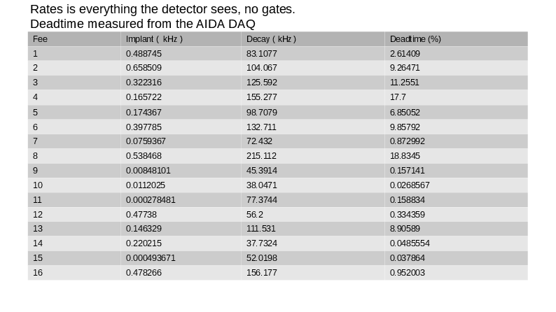
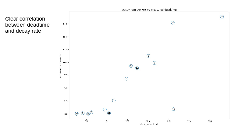
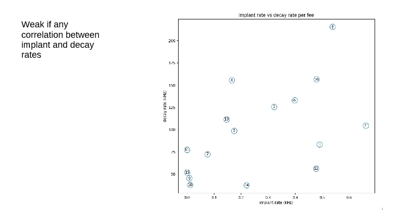
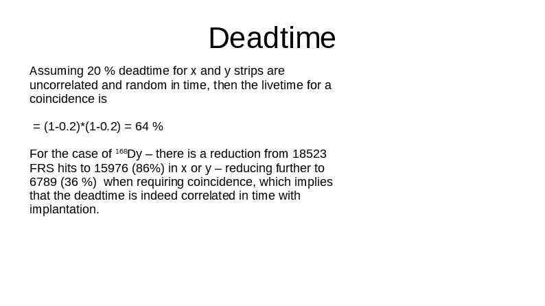
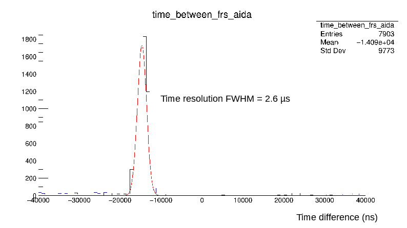
Analysis done by JEL of the AIDA daq with his own time-stitcher -- not the standard one used by DESPEC.
- Analysis of 168Dy:
-- Correlation efficiency and stopping layer of ion 168Dy in fully-stripped and hydrogen-like charge-state.
|
| Attachment 1: aidastop.pdf
|
|
|
744
|
Thu Nov 13 10:14:50 2025 |
JB, MP | Noise conditions after removal of bPlast cabling |
JB has removed unnecessary cables and items from the snout and platform:
- the bPlast cables and booster boards were removed
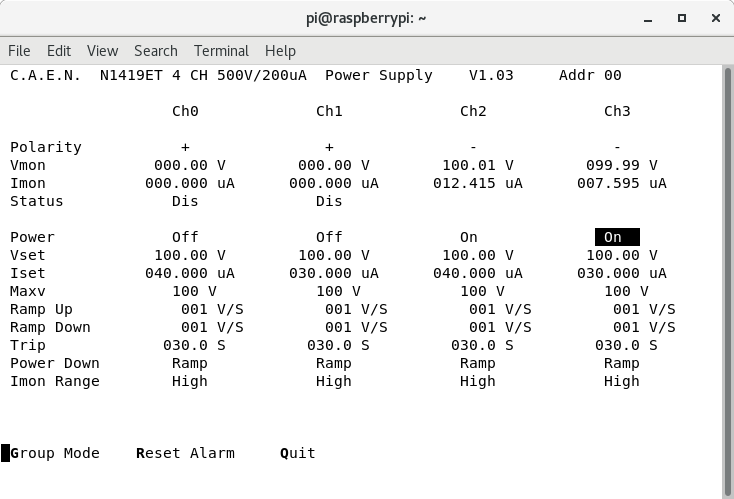
- crate below the AIDA frame was disconnected from the power supply
- BB7 cables were removed
- power supply for the booster boards was removed
We switch on the system and check the noise conditions.
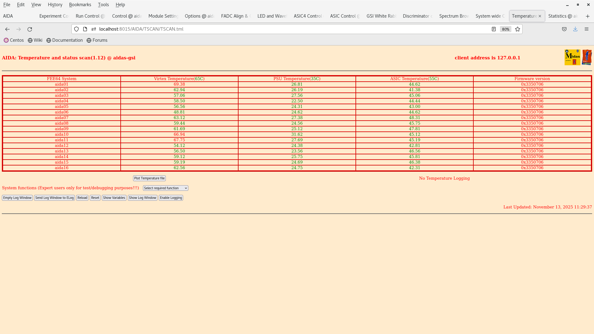
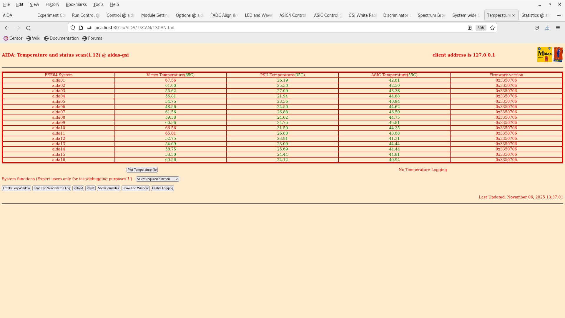
We started up. BIAS OK. TEMPS OK.
Thresholds initially set to 100 keV.
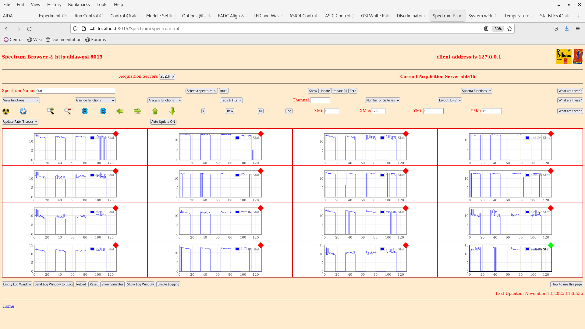
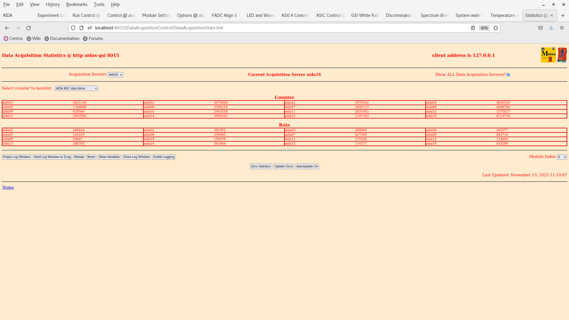
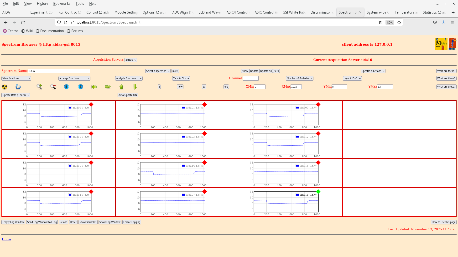
Rates in all FEEs are > 200 kHZ. Attachment 6.
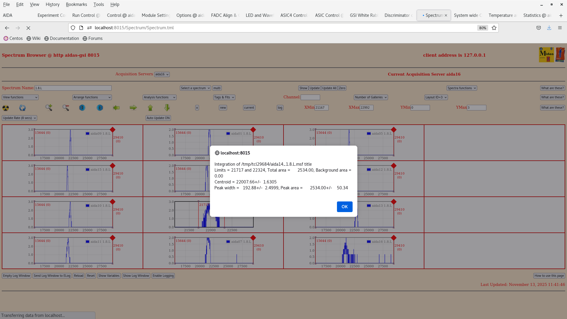
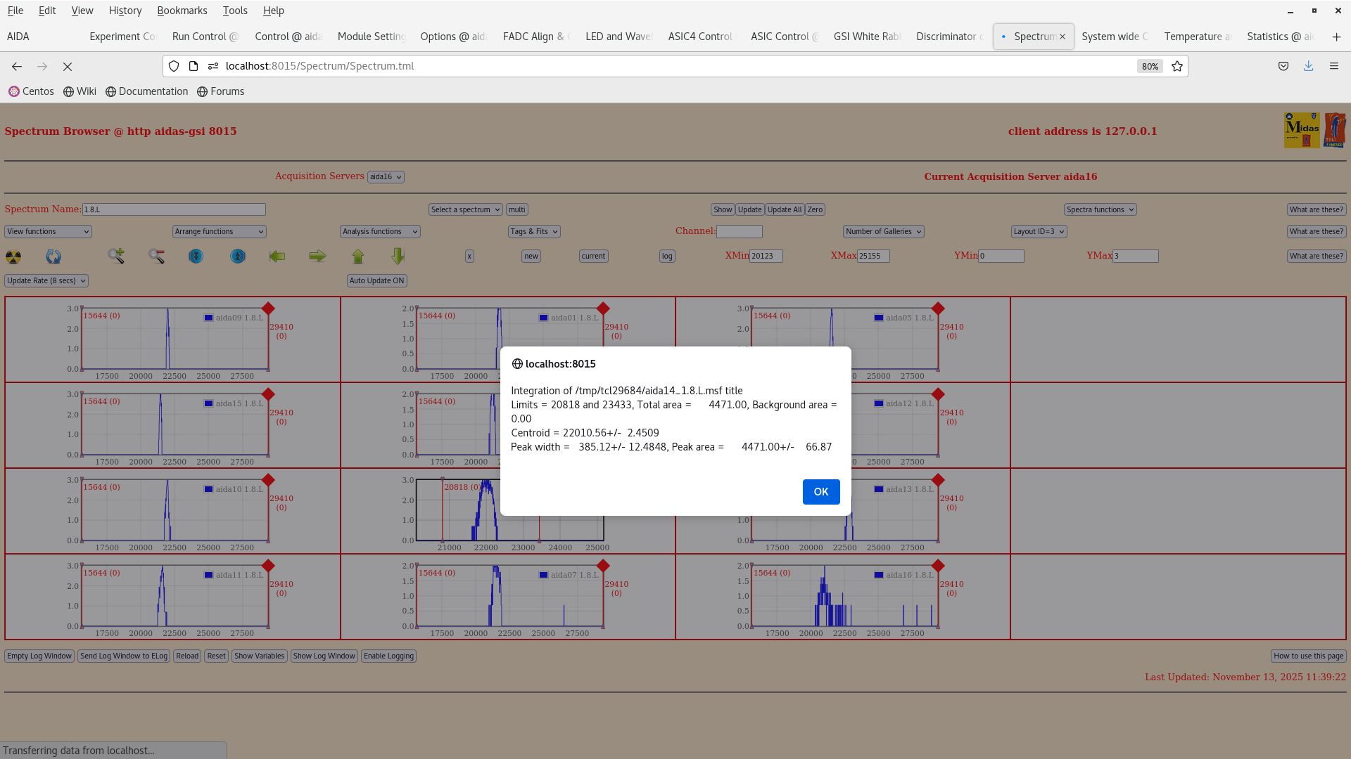
We then checked the pulser peak widths in aida14. --> 192 channels with 1 V 1x attenuation. at 700 keV threshold (attachment 3). At 100 keV threshold the peak width was significantly higher!!! ---> 385 channels (attachment 2)
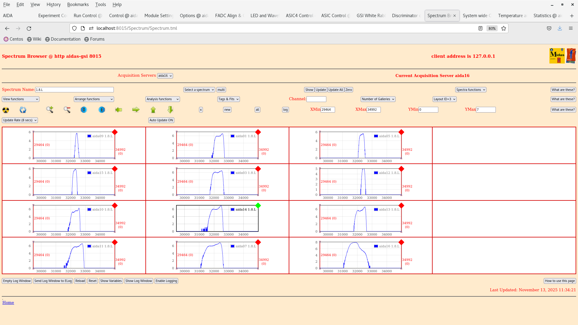
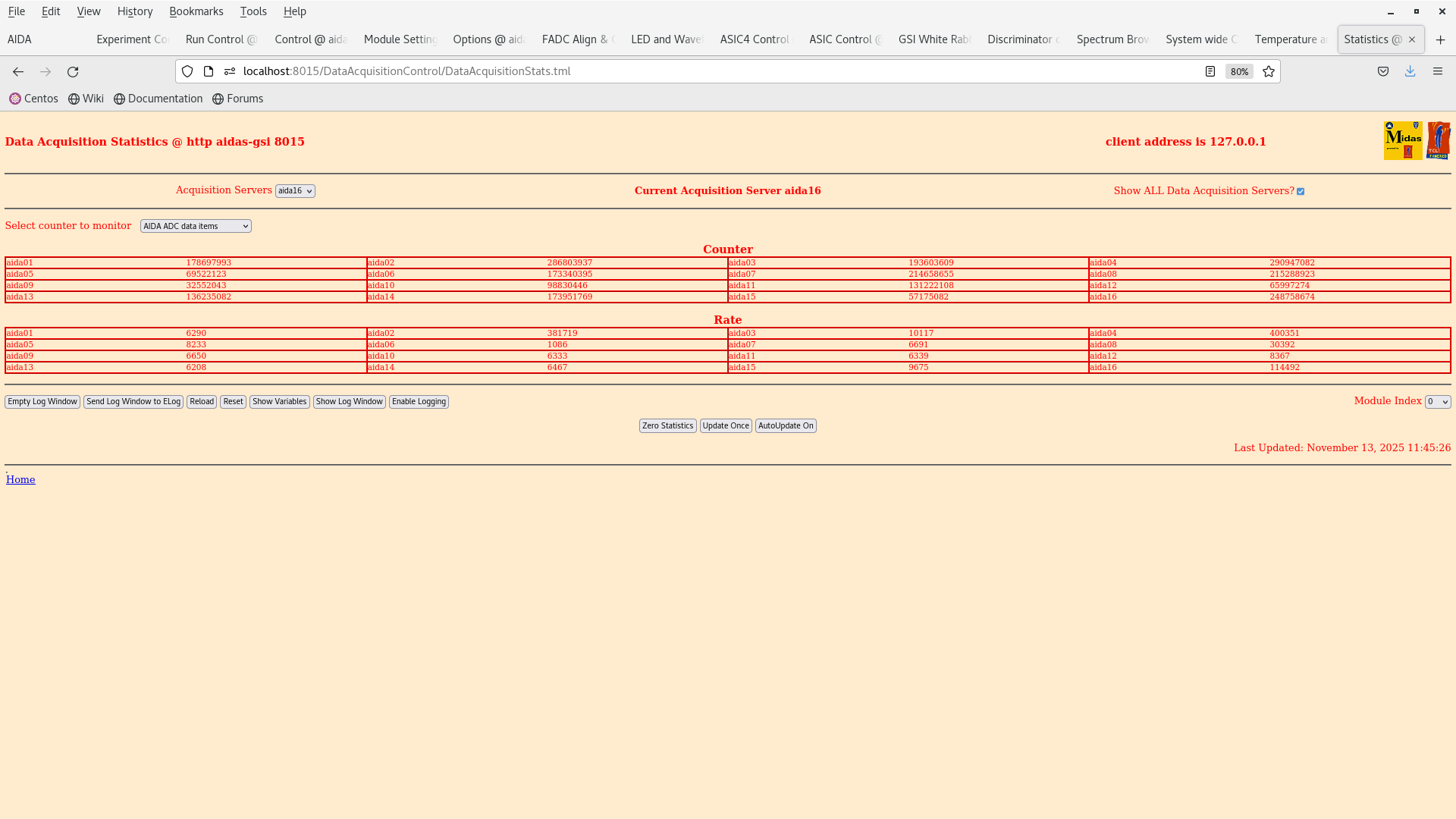
We checked the rates in the FEEs with the 700 keV thresholds (attachment 11).
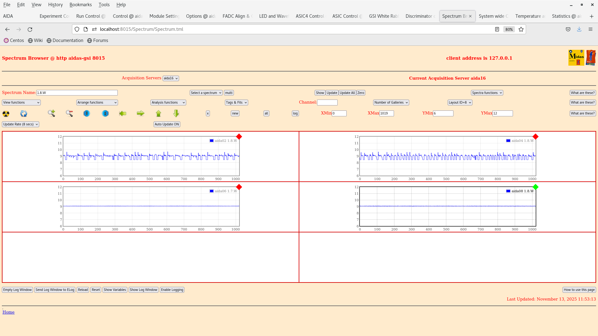
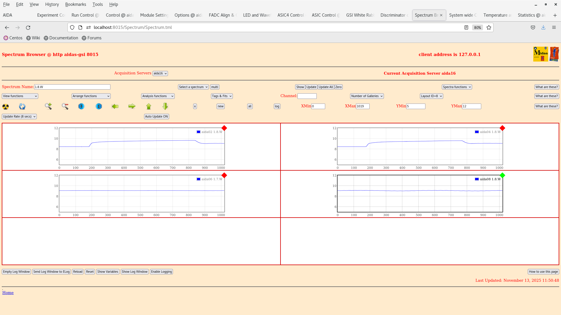
Furthermore, we checked the constant noise that appears to be present in the y FEEs aida02,04,06,08. This can be seen in attachment 8 and has been noted in previous elogs https://elog.ph.ed.ac.uk/DESPEC/727
Info on current status of ion catcher: vacuum system is ON, electronics is also on (RF ~2MHz) on the side opposite to the DESPEC setup |
| Attachment 1: Screenshot_from_2025-11-13_11-17-27.png
|
|
| Attachment 2: Screenshot_from_2025-11-13_11-41-48.png
|
|
| Attachment 3: Screenshot_from_2025-11-13_11-39-30.png
|
|
| Attachment 4: Screenshot_from_2025-11-13_11-34-29.png
|
|
| Attachment 5: Screenshot_from_2025-11-13_11-33-38.png
|
|
| Attachment 6: Screenshot_from_2025-11-13_11-33-13.png
|
|
| Attachment 7: Screenshot_from_2025-11-13_11-29-41.png
|
|
| Attachment 8: Screenshot_from_2025-11-13_11-53-18.png
|
|
| Attachment 9: Screenshot_from_2025-11-13_11-50-53.png
|
|
| Attachment 10: Screenshot_from_2025-11-13_11-47-30.png
|
|
| Attachment 11: Screenshot_from_2025-11-13_11-45-30.png
|
|
|
743
|
Fri Nov 7 12:30:30 2025 |
JB, GB, MP | Pulser walkthrough for source tests. |
13:30 We are going to do the pulser walkthrough for the the source tests.

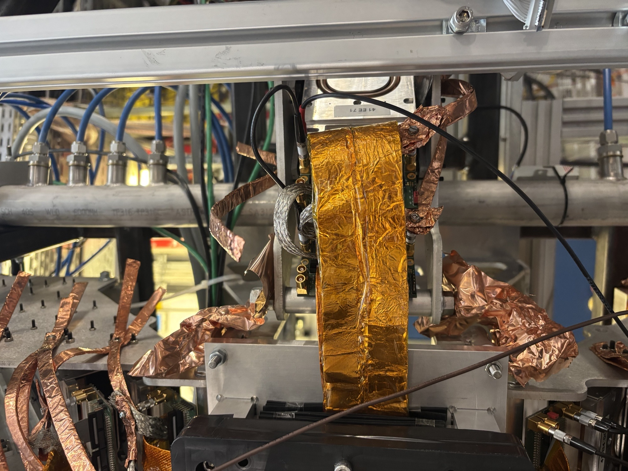
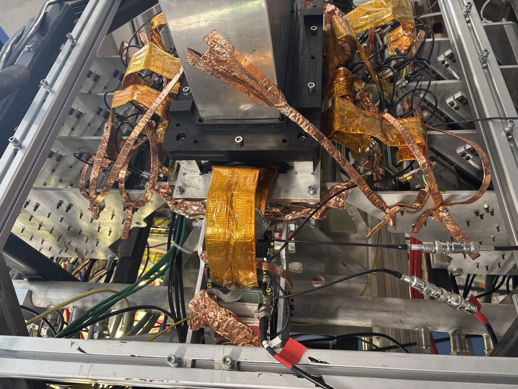
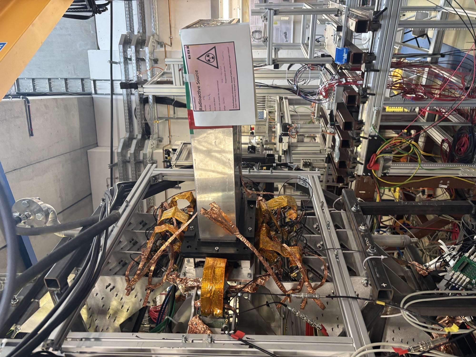
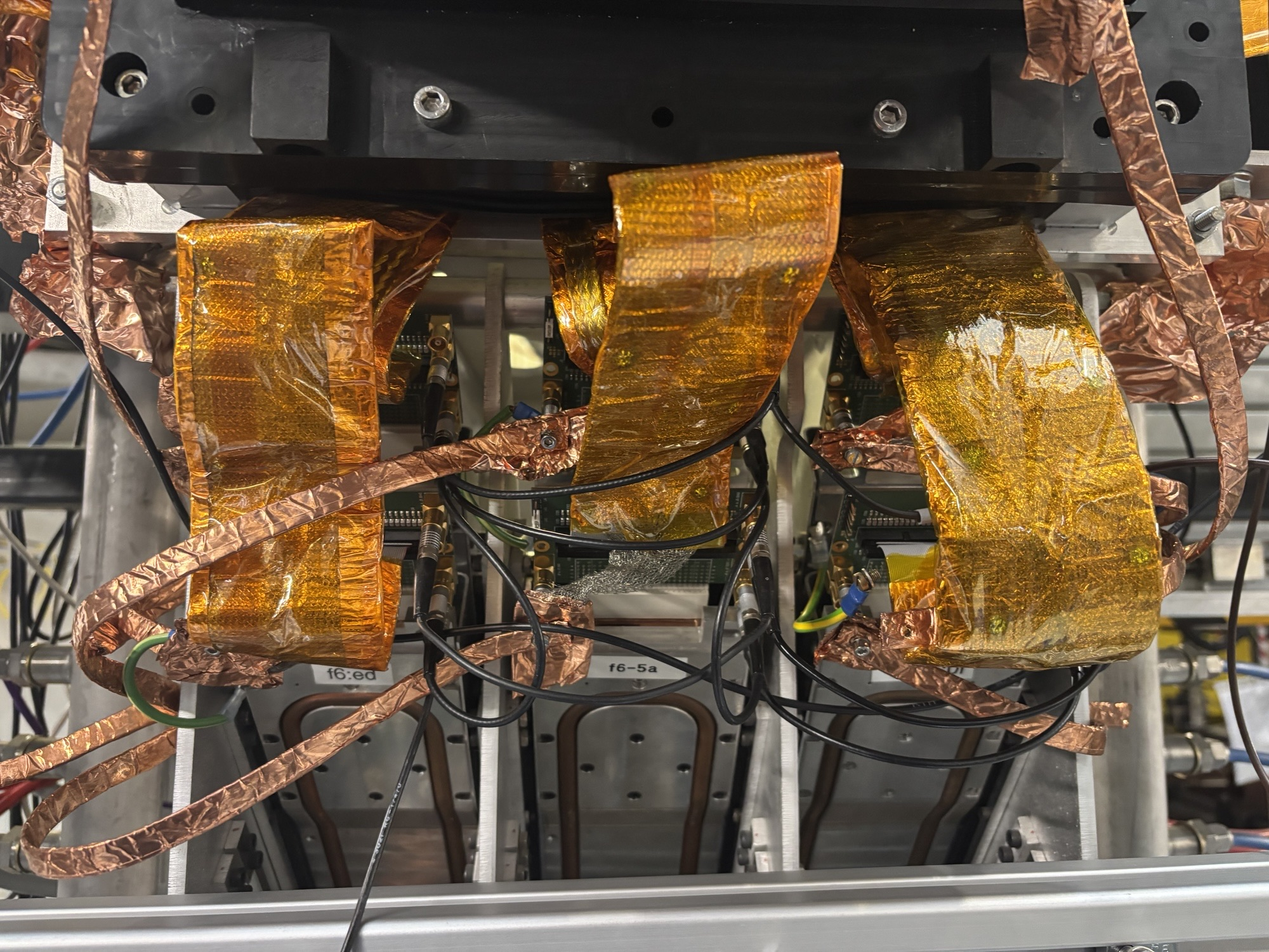
We are wrapping the snout in some copper first to further establish a better connection with the ground.

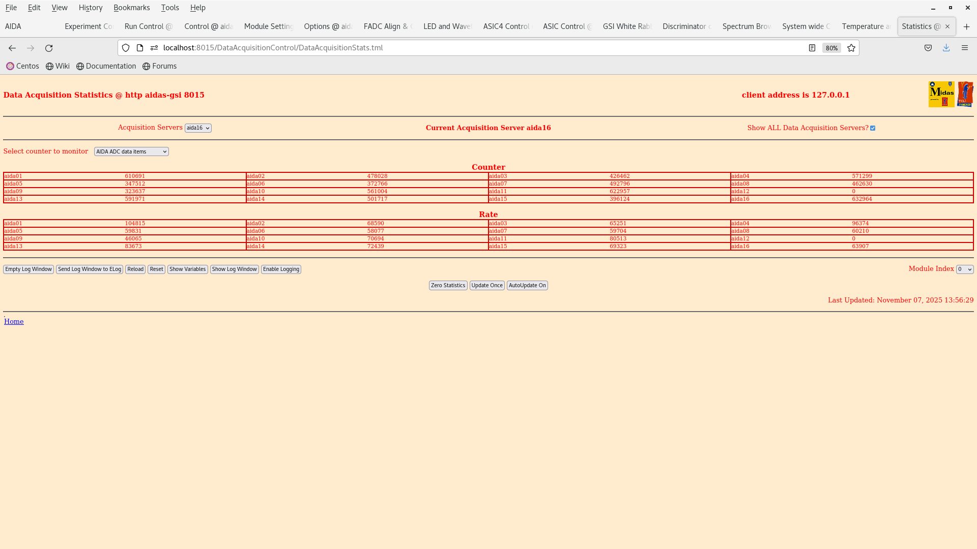
2025Nov07-13.55.01 is a setting with 100 keV threshold across all FEEs.

We got the DAQ running, TEMPS ok and biased OK. We execute the pulser walkthrough as follow:

10x attenuation - 10V -> 1V in steps of 1 V

/lustre/despec/aida_sourcetest_2025/raw/

pulser_wt_10V - 10V

pulser_wt_9V - 9V

pulser_wt_8V - 8V

pulser_wt_7V - 7V

pulser wt_6V - 6V

pulser_wt_5V - 5V

pulser_wt_4V - 4V

pulser_wt_3V - 3V

pulser_wt_2V - 2V

pulser_wt_1V - 1V

Data taking stopped and we turn off the system to a safe state.

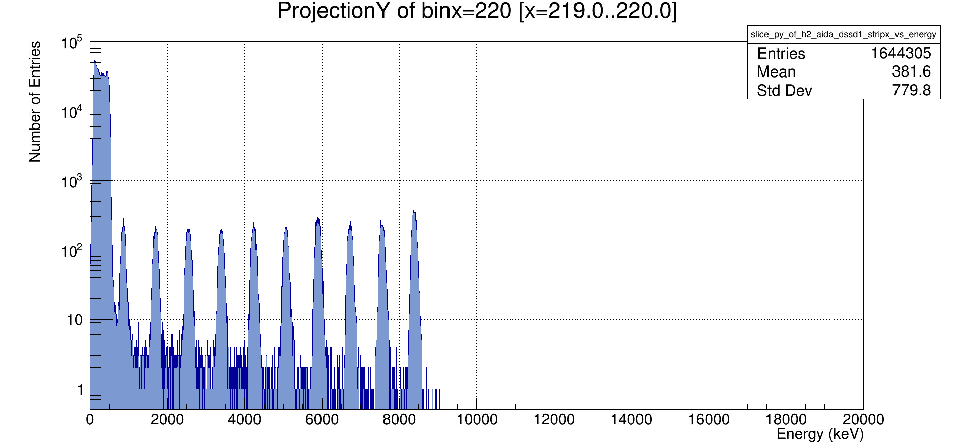
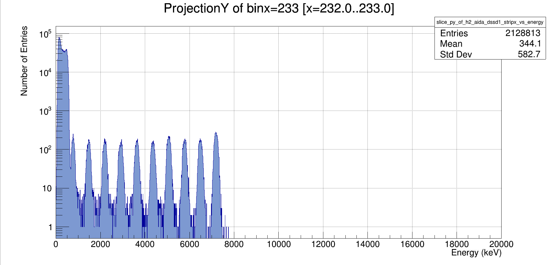
Initial analysis of the raw ADC spectra can be seen in attachment 4 & 5. |
| Attachment 1: Screenshot_from_2025-11-07_13-56-34.png
|
|
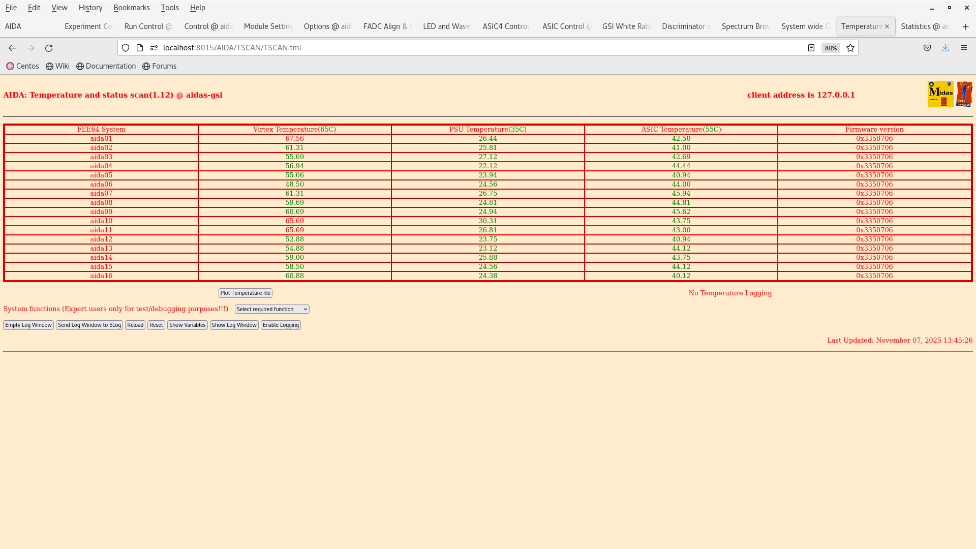
| Attachment 2: Screenshot_from_2025-11-07_13-45-30.png
|
|
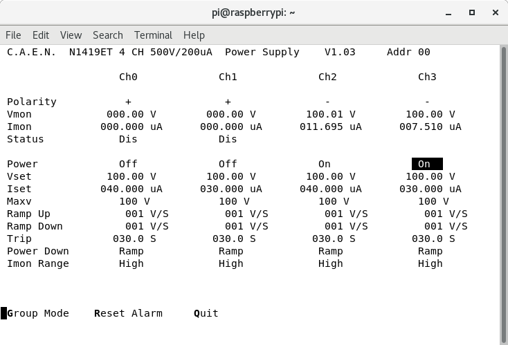
| Attachment 3: Screenshot_from_2025-11-07_13-43-50.png
|
|
| Attachment 4: Screenshot_2025-11-07_192947.png
|
|
| Attachment 5: Screenshot_2025-11-07_193005.png
|
|
|
742
|
Fri Nov 7 10:47:29 2025 |
MP | 207Bi source test - data taking |
DAQ stopped at ~17.30 due to anydesk failure


> Restart AIDA
>
> aida06 took three attempts to boot today :(
>
> All system checks OK, ASICs aligned
>
> Run DAQ without merger - looks okay, all FEEs working
>
> When connecting to merger aida15 drops connection, solution restart merger
>
> Aida13 not sending data - do an ASIC check/load
>
> Finally all DAQs send data, merger is happy with all 16 FEEs
>
> Open run R6 on disk |
|
741
|
Thu Nov 6 12:58:09 2025 |
NH | 207Bi source test - data taking |
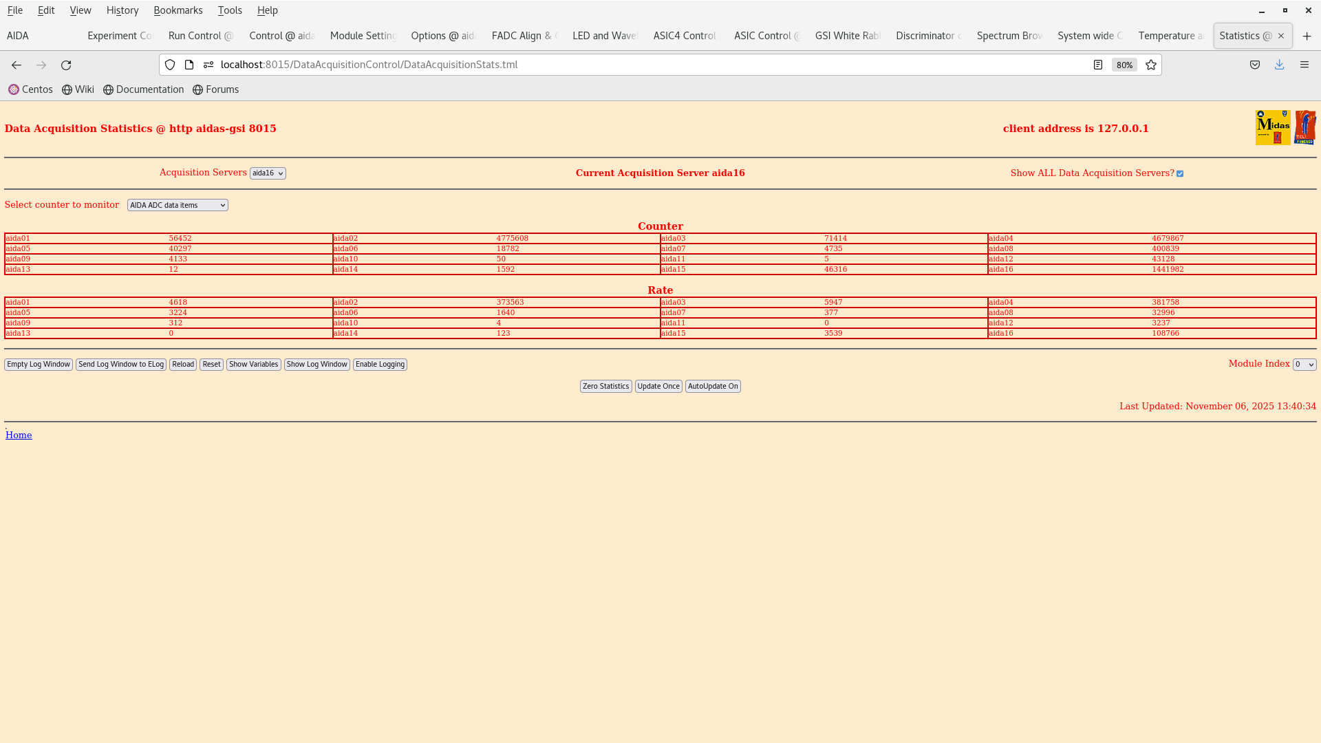
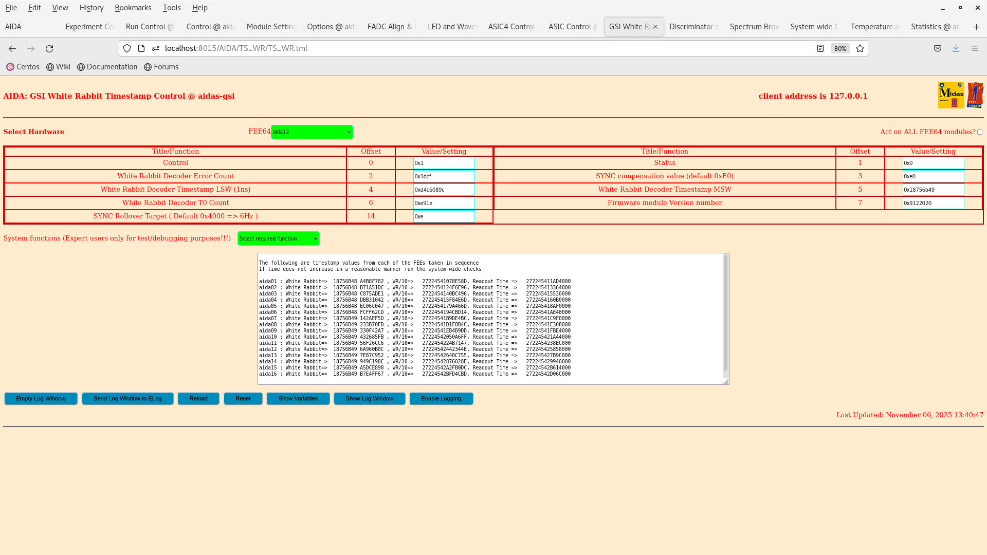
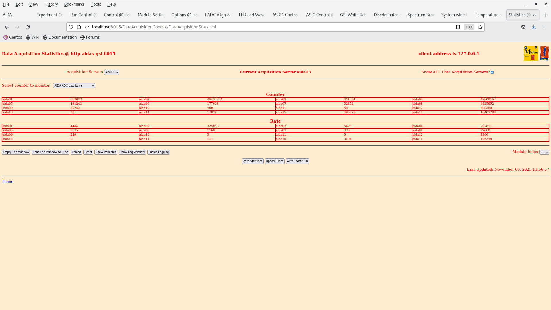
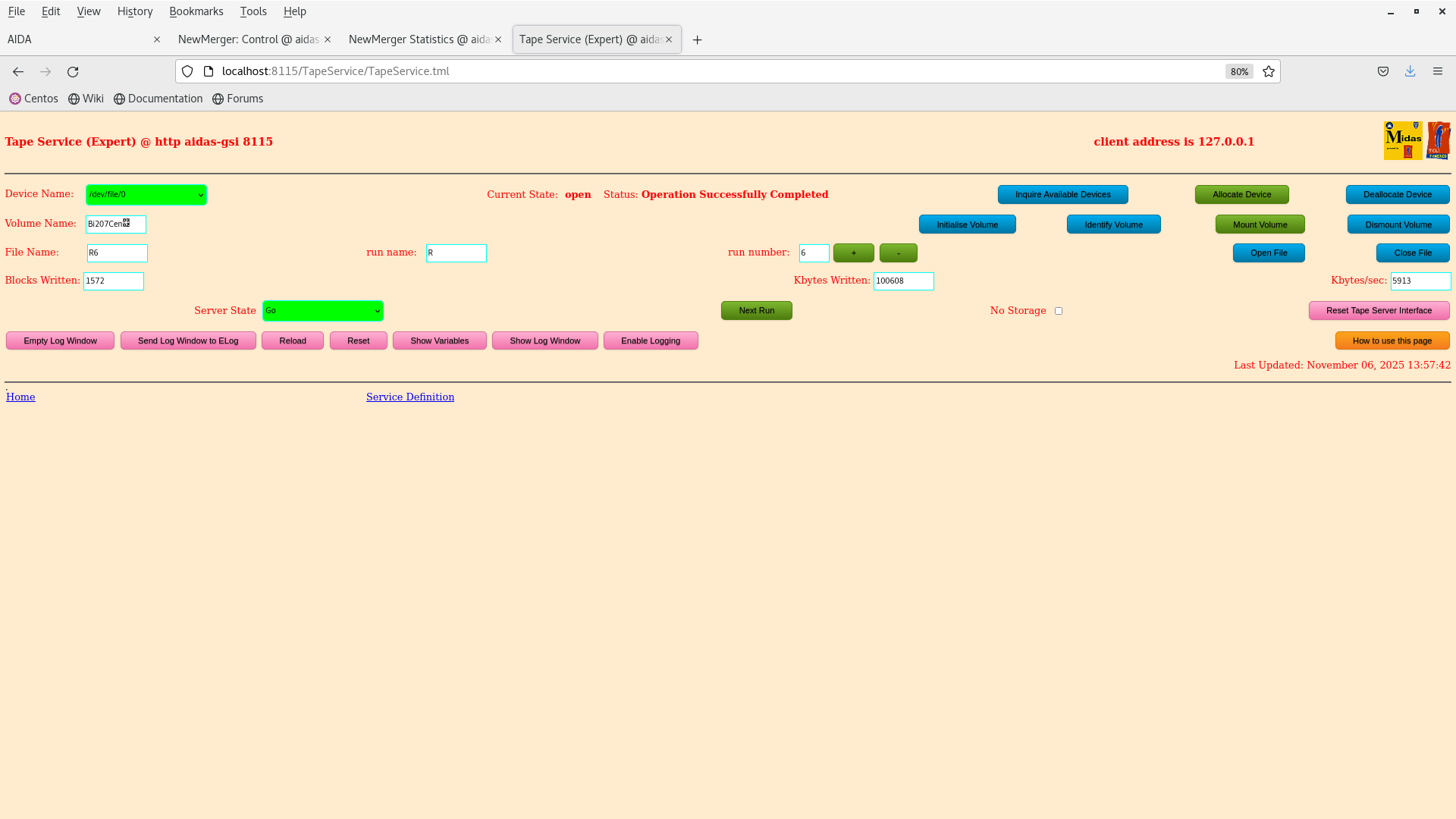
Restart AIDA

aida06 took three attempts to boot today :(

All system checks OK, ASICs aligned

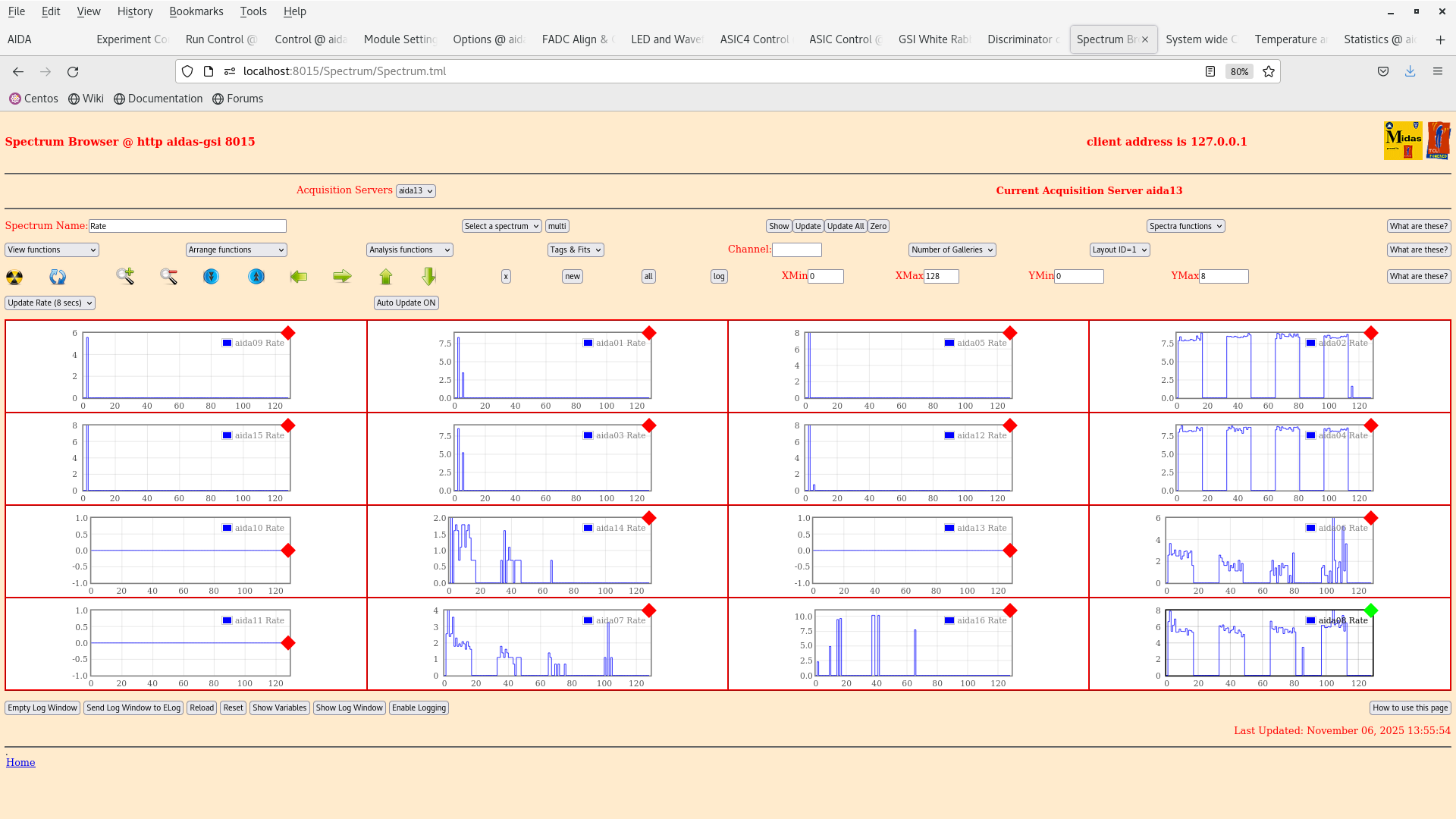
Run DAQ without merger - looks okay, all FEEs working

When connecting to merger aida15 drops connection, solution restart merger

Aida13 not sending data - do an ASIC check/load

Finally all DAQs send data, merger is happy with all 16 FEEs

Open run R6 on disk |
| Attachment 1: Screenshot_from_2025-11-06_13-37-10.png
|
|
| Attachment 2: Screenshot_from_2025-11-06_13-40-37.png
|
|
| Attachment 3: Screenshot_from_2025-11-06_13-40-50.png
|
|
| Attachment 4: Screenshot_from_2025-11-06_13-55-58.png
|
|
| Attachment 5: Screenshot_from_2025-11-06_13-57-00.png
|
|
| Attachment 6: Screenshot_from_2025-11-06_13-57-43.png
|
|
|
740
|
Wed Nov 5 13:23:38 2025 |
JB, MP | 207Bi source test - FWHM tests |
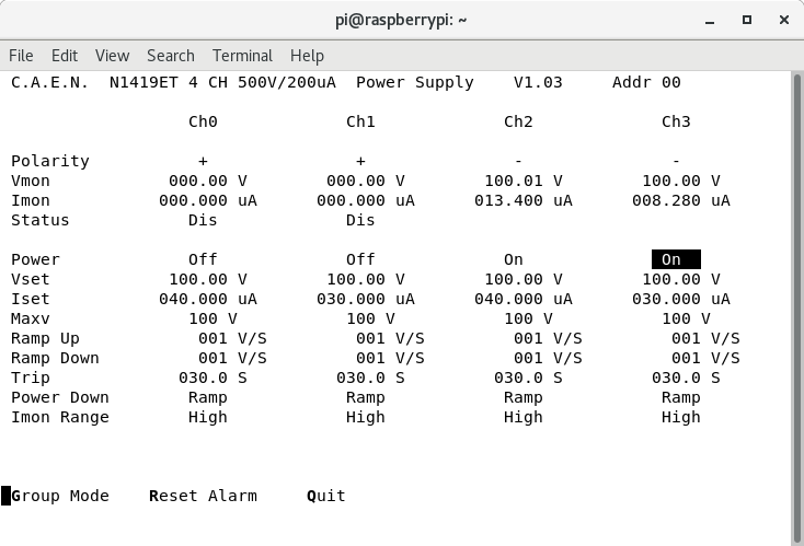
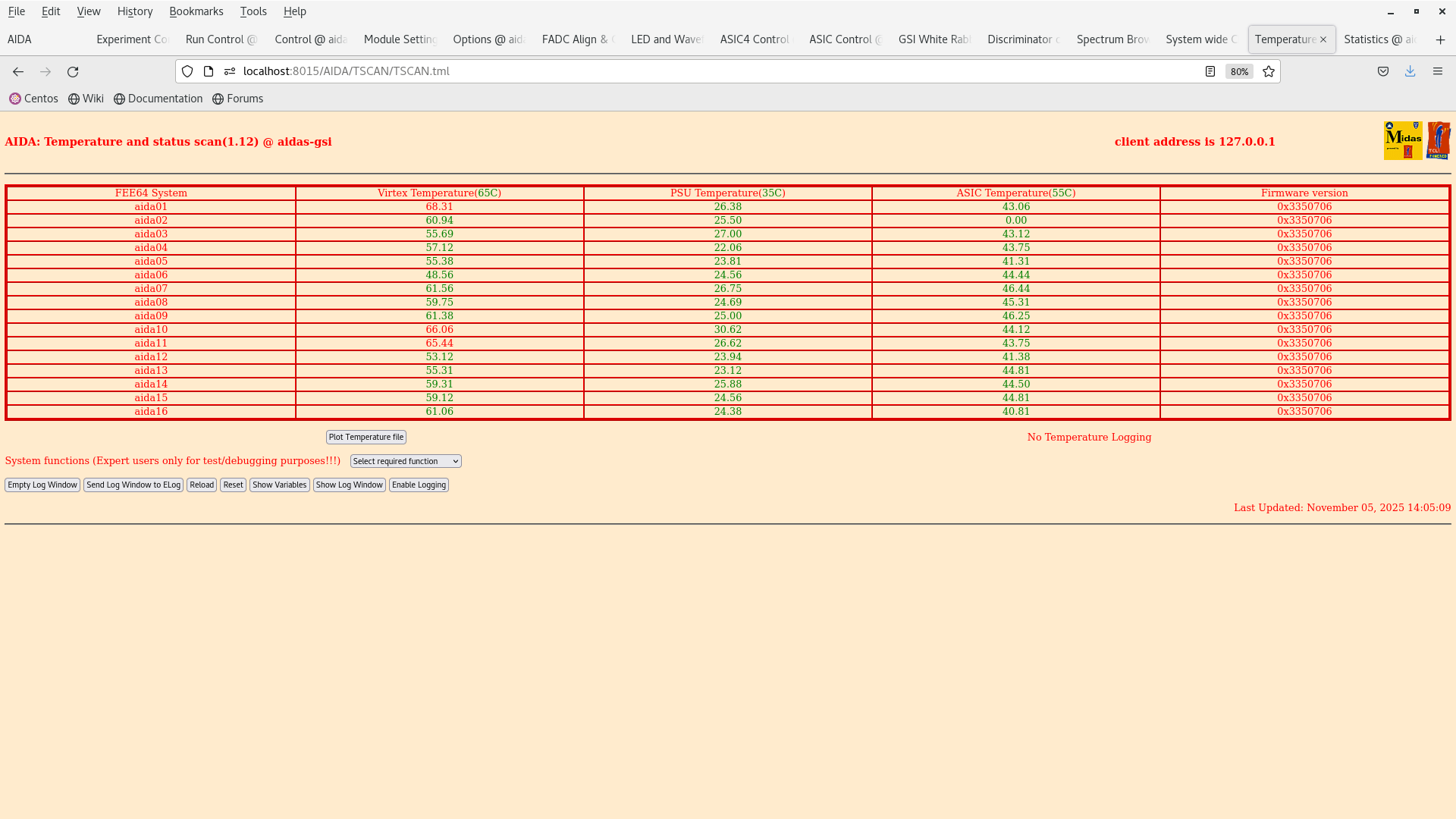
14:10 started up the DAQ. HV and TEMPS OK.

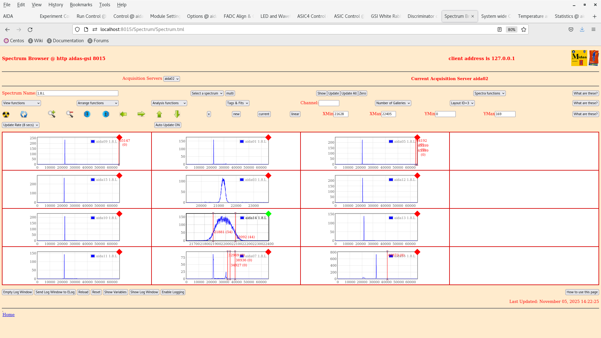
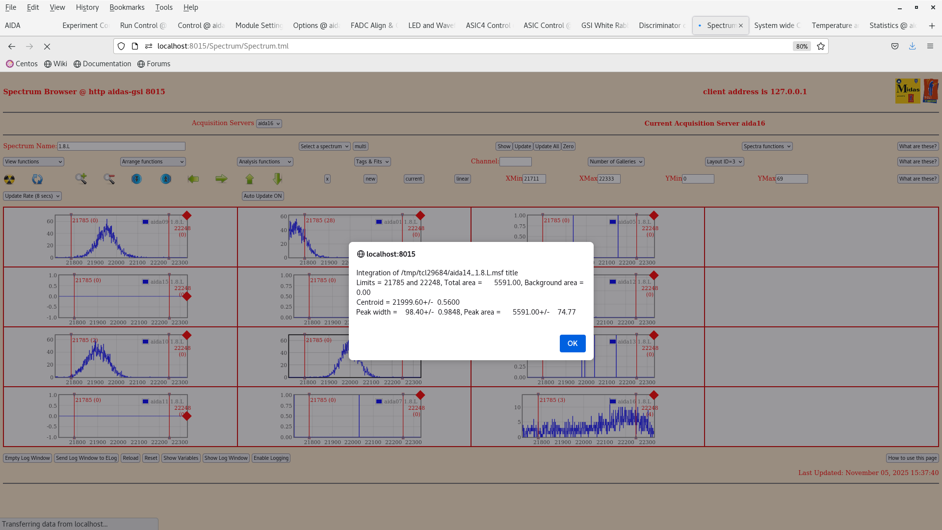
Peak threshold with 1V pulser measured at ~ 175 ADC channels. Attachment 3.

14:24 DAQ stopped and detector debiased. We are going to do the following:

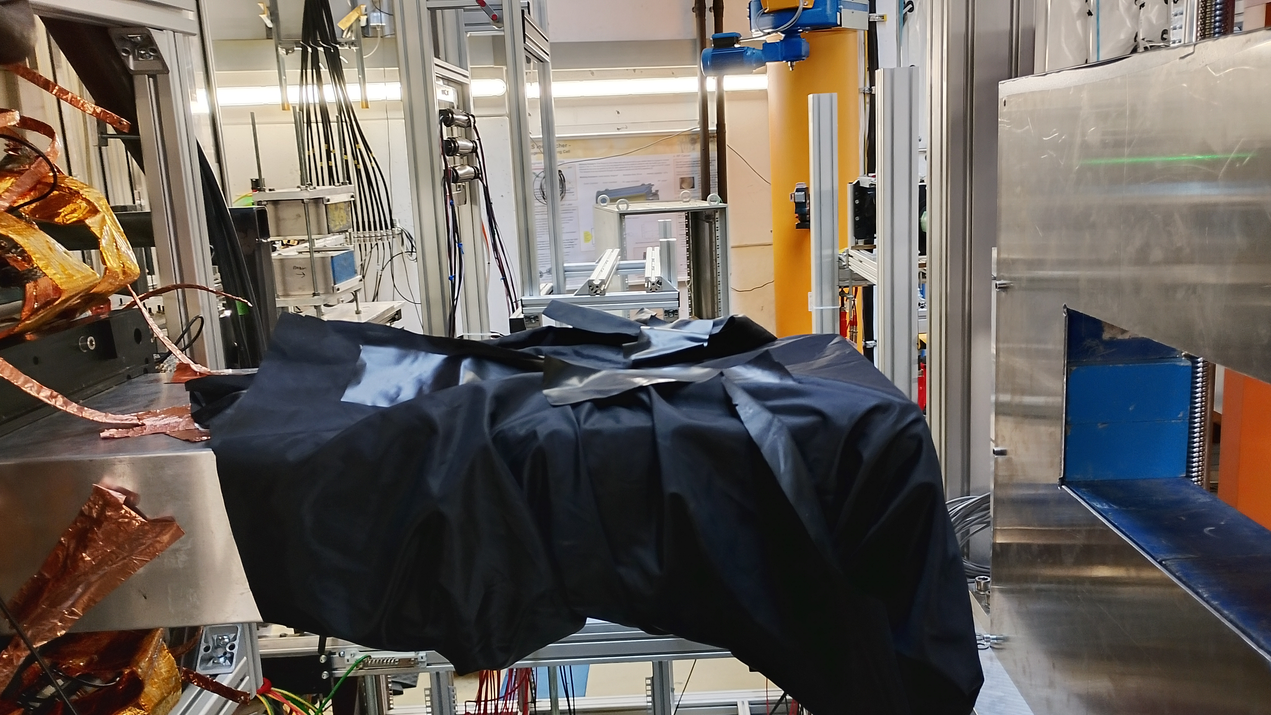
1. Cover the snout with a black cloth to check if it is light tight!
2. Disconnect the detector signal cable from the FEE64 adaptor card of aida14.

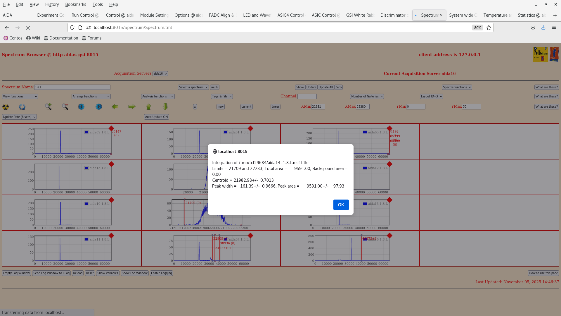
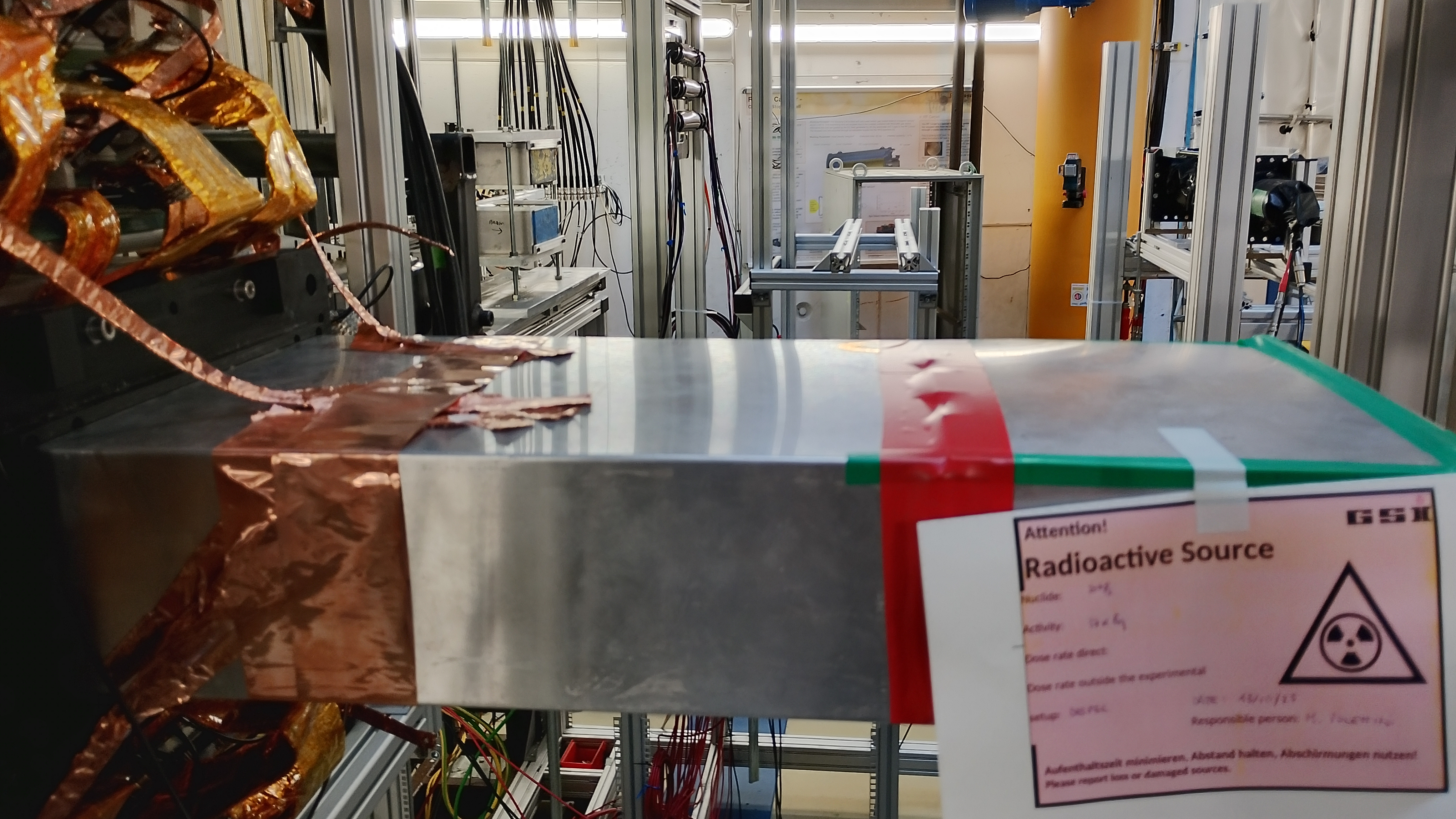
We put a black cloth cover over the snout, but pulser peak width remained the same ~161 ADC channel. Attachment 4,5.

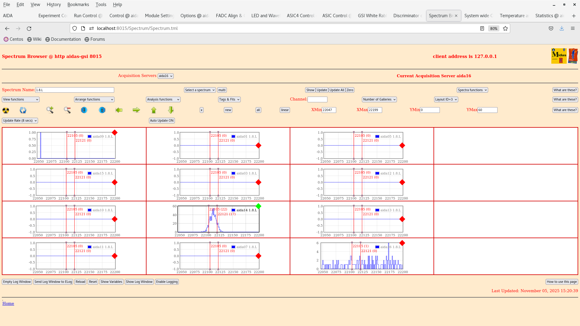
We disconnected the cable from aida14 and the FWHM pf the pulser is ~15 ADC channels (as expected)

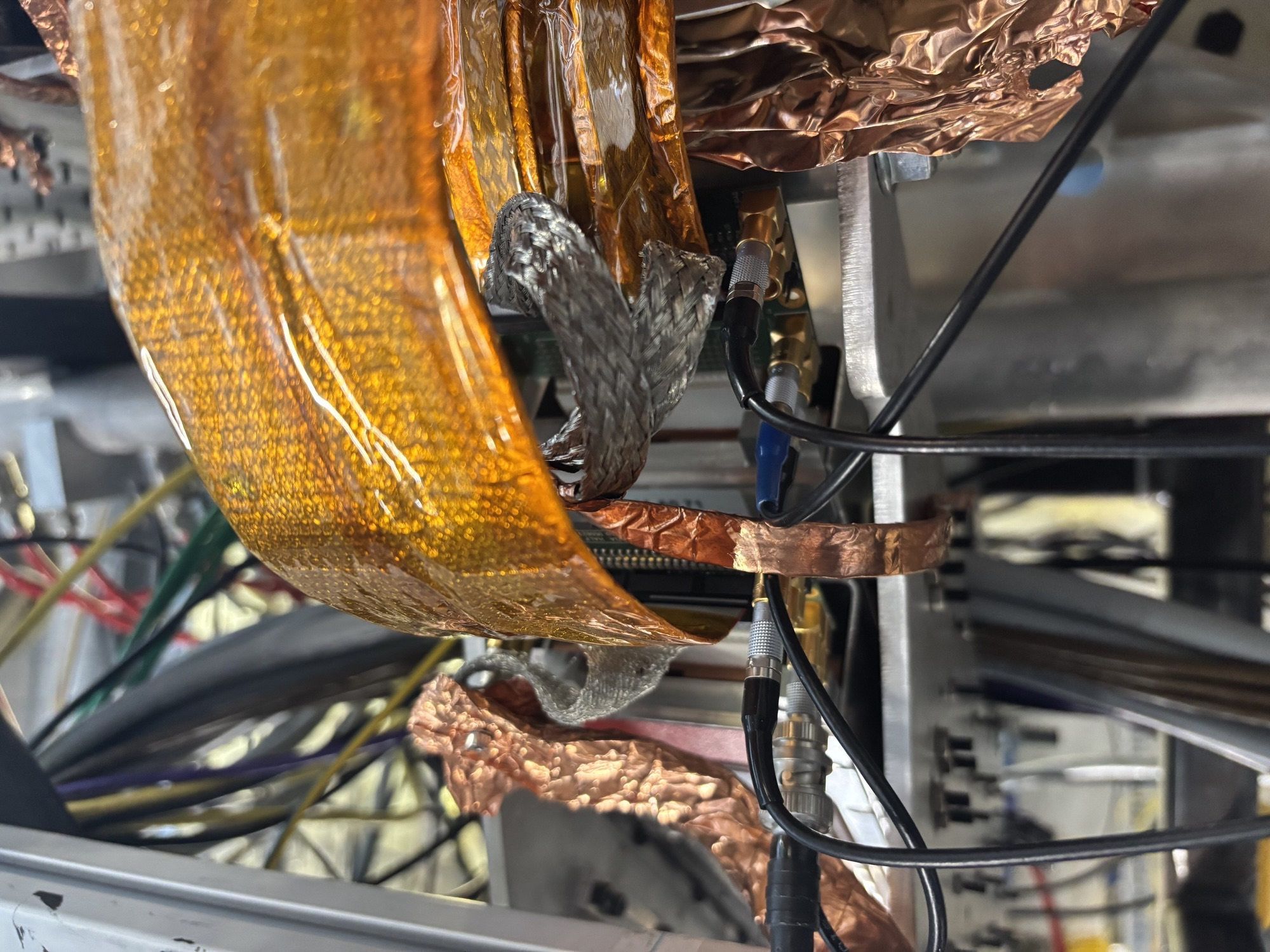
Wrapped the snout with more copper tape at the point where the PCB ground makes contact with the snout to ensure better contact, this seems to improve the FWHM to ~95 ADC channels |
| Attachment 1: Screenshot_from_2025-11-05_14-05-24.png
|
|
| Attachment 2: Screenshot_from_2025-11-05_14-05-14.png
|
|
| Attachment 3: Screenshot_from_2025-11-05_14-22-57.png
|
|
| Attachment 4: IMG_20251105_143017_hdr.jpg
|
|
| Attachment 5: Screenshot_from_2025-11-05_14-46-44.png
|
|
| Attachment 6: Screenshot_from_2025-11-05_15-20-45.png
|
|
| Attachment 7: Screenshot_from_2025-11-05_15-37-47.png
|
|
| Attachment 8: IMG_20251105_154023_hdr.jpg
|
|
|
739
|
Tue Nov 4 17:29:28 2025 |
MP | Bi207 source data, 700keV |
Anydesk has crashed. I am not able to set it up again. I switch off bias and fees
| Quote: |
|
Some FEES were not acquiring data for some reason we could not understand. We lowered the thresholds to 200 keV, then rose them again to 700 keV. It seems they are now acquiring. We start data taking again.
| Quote: |
|
- Bias and basic checks: the pulser FWHM appears to be ~170, which is the same we have obtained at the end of last week.
- Initialised the Merger and Tape server
- loading of settings: EXPERIMENTS/AIDA/2025Nov03-16.21.44
- slow comparator thresholds set to 700 keV for all X FEES
- y FEEs disabled in the discriminator
- Starting data taking with following details:
MIDAS data in: Bi207Centre_700
MBS data in /lustre/despec/aida_sourcetest_2025/raw started from lxg3138 on screen ('AIDAdaq')
We take data overnight in this configuration and continue the grounding checks tomorrow
|
|
|
|
738
|
Tue Nov 4 16:34:47 2025 |
MP, NH | Bi207 source data, 700keV |
Some FEES were not acquiring data for some reason we could not understand. We lowered the thresholds to 200 keV, then rose them again to 700 keV. It seems they are now acquiring. We start data taking again.
| Quote: |
|
- Bias and basic checks: the pulser FWHM appears to be ~170, which is the same we have obtained at the end of last week.
- Initialised the Merger and Tape server
- loading of settings: EXPERIMENTS/AIDA/2025Nov03-16.21.44
- slow comparator thresholds set to 700 keV for all X FEES
- y FEEs disabled in the discriminator
- Starting data taking with following details:
MIDAS data in: Bi207Centre_700
MBS data in /lustre/despec/aida_sourcetest_2025/raw started from lxg3138 on screen ('AIDAdaq')
We take data overnight in this configuration and continue the grounding checks tomorrow
|
|
|
737
|
Tue Nov 4 14:57:19 2025 |
MP | Bi207 source data, 700keV |
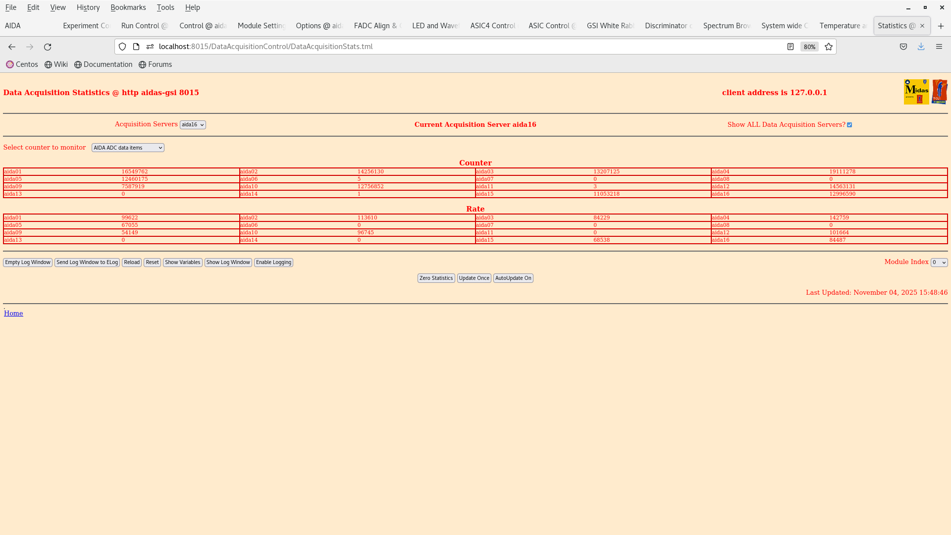
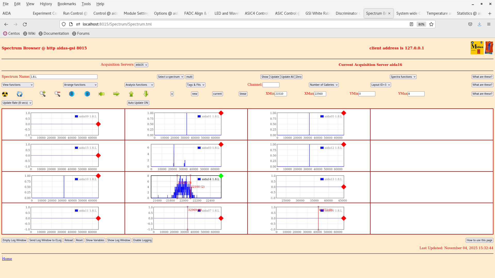
- Bias and basic checks: the pulser FWHM appears to be ~170, which is the same we have obtained at the end of last week.
- Initialised the Merger and Tape server
- loading of settings: EXPERIMENTS/AIDA/2025Nov03-16.21.44
- slow comparator thresholds set to 700 keV for all X FEES
- y FEEs disabled in the discriminator
- Starting data taking with following details:
MIDAS data in: Bi207Centre_700
MBS data in /lustre/despec/aida_sourcetest_2025/raw started from lxg3138 on screen ('AIDAdaq')
We take data overnight in this configuration and continue the grounding checks tomorrow |
| Attachment 1: Screenshot_from_2025-11-04_15-49-20.png
|
|
| Attachment 2: Screenshot_from_2025-11-04_15-33-11.png
|
|
| Attachment 3: Screenshot_from_2025-11-04_15-28-42.png
|
|
| Attachment 4: Screenshot_from_2025-11-04_15-28-35.png
|
|
|
736
|
Thu Oct 30 16:43:36 2025 |
MP, NH | Setup and data taking with 207Bi |
Data taking and DAQ stopped now (17.40)
| Quote: |
|
- Initialised the Merger and Tape server
- loading of settings: EXPERIMENTS/AIDA/2025Oct29-16.11.06
- aida16 very noisy (attachments 3,4), slow comparator thresholds was risen to 500 keV, until reducing its deadtime to 0
- y FEEs disabled in the discriminator (example in attachment 5)
- Starting data taking with following details:
MIDAS data in: Bi207Centre
MBS data in /lustre/despec/aida_sourcetest_2025/raw started from lxg3138 on screen ('AIDAdaq')
|
|
|
735
|
Thu Oct 30 10:06:21 2025 |
MP, NH | Setup and data taking with 207Bi |
- Initialised the Merger and Tape server
- loading of settings: EXPERIMENTS/AIDA/2025Oct29-16.11.06
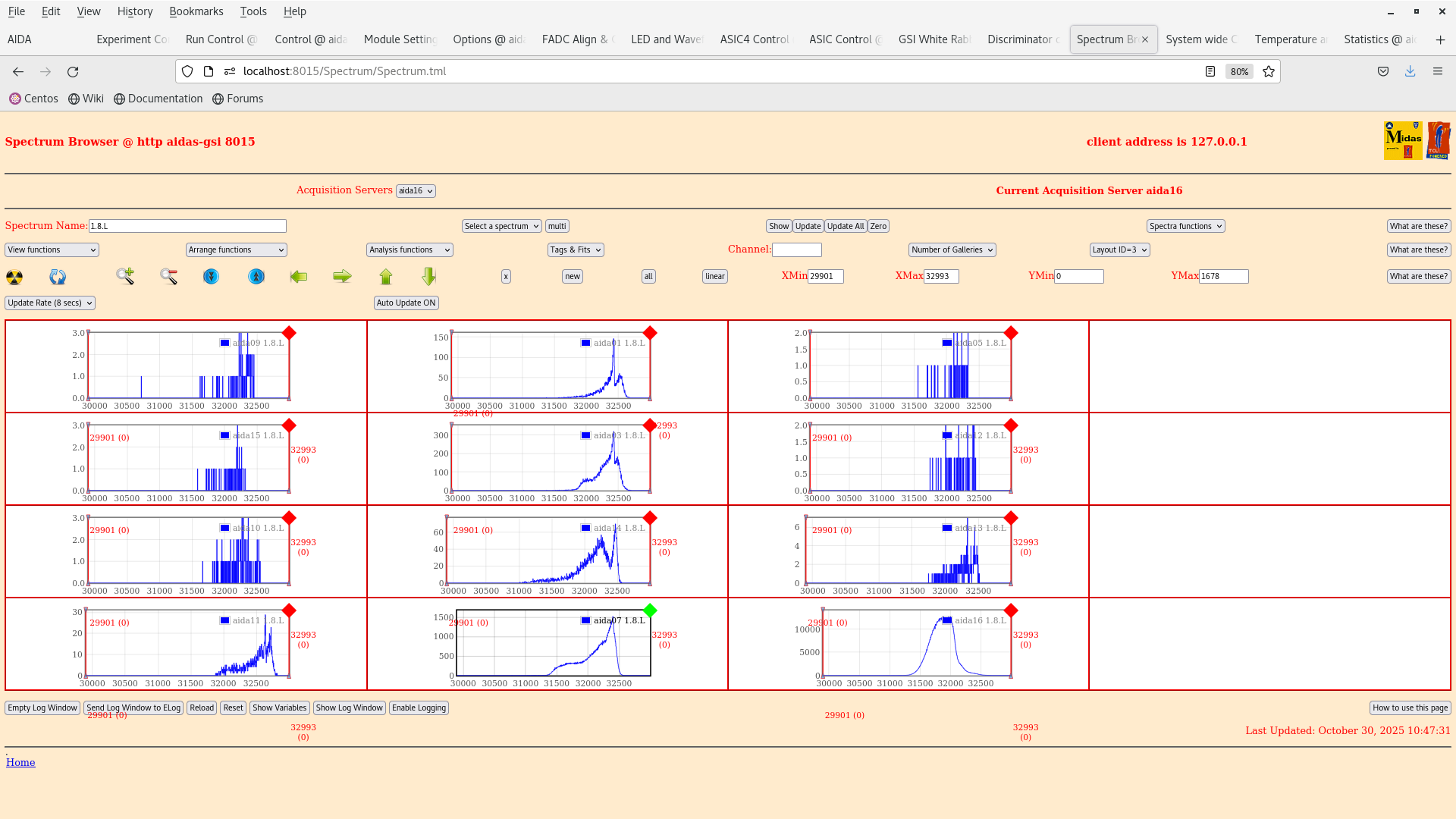
- aida16 very noisy (attachments 3,4), slow comparator thresholds was risen to 500 keV, until reducing its deadtime to 0
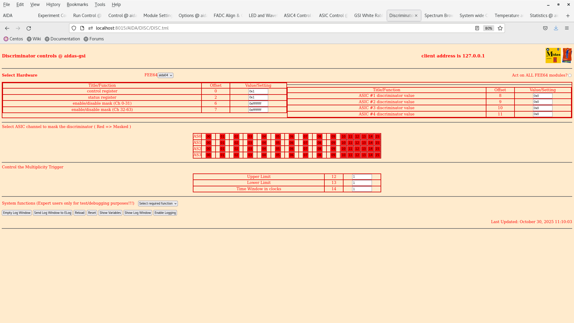
- y FEEs disabled in the discriminator (example in attachment 5)
- Starting data taking with following details:
MIDAS data in: Bi207Centre
MBS data in /lustre/despec/aida_sourcetest_2025/raw started from lxg3138 on screen ('AIDAdaq') |
| Attachment 1: Screenshot_from_2025-10-30_11-07-55.png
|
|
| Attachment 2: Screenshot_from_2025-10-30_11-07-39.png
|
|
| Attachment 3: Screenshot_from_2025-10-30_11-07-29.png
|
|
| Attachment 4: Screenshot_from_2025-10-30_11-08-07.png
|
|
| Attachment 5: Screenshot_from_2025-10-30_11-10-06.png
|
|
|
734
|
Wed Oct 29 14:11:01 2025 |
JB, MP | 207Bi source test - data taking |
15:10 MP entered and check the water pressure OK.
15:10 DSSSDs biased - OK.

The plan from https://elog.ph.ed.ac.uk/DESPEC/719


- Energy distribution in x and y for ADC items and cluster
- The cluster size from conversion electrons
- ADC offsets with the 207Bi source after performing a pulser walkthrough
- Threshold test /w a 207Bi source - varying the threshold as while the source is in place and seeing when the 207Bi peaks are cut off.
- Background run without the 207Bi source (after the above tests)
- Possible test with a 152Eu source as well to measure conversion electrons from Eu could also be an option but we would need to discuss how to do this since all the 152Eu source are closed. We could possibly measure the compton edge from this
data.

Currently the n+n ohmic channels are too noisy to be used for the test. So we will disable their readout for the data taking.

All system wide checks passed. ADC calibration not (but we don't care since we aren't looking at waveforms... for now...).

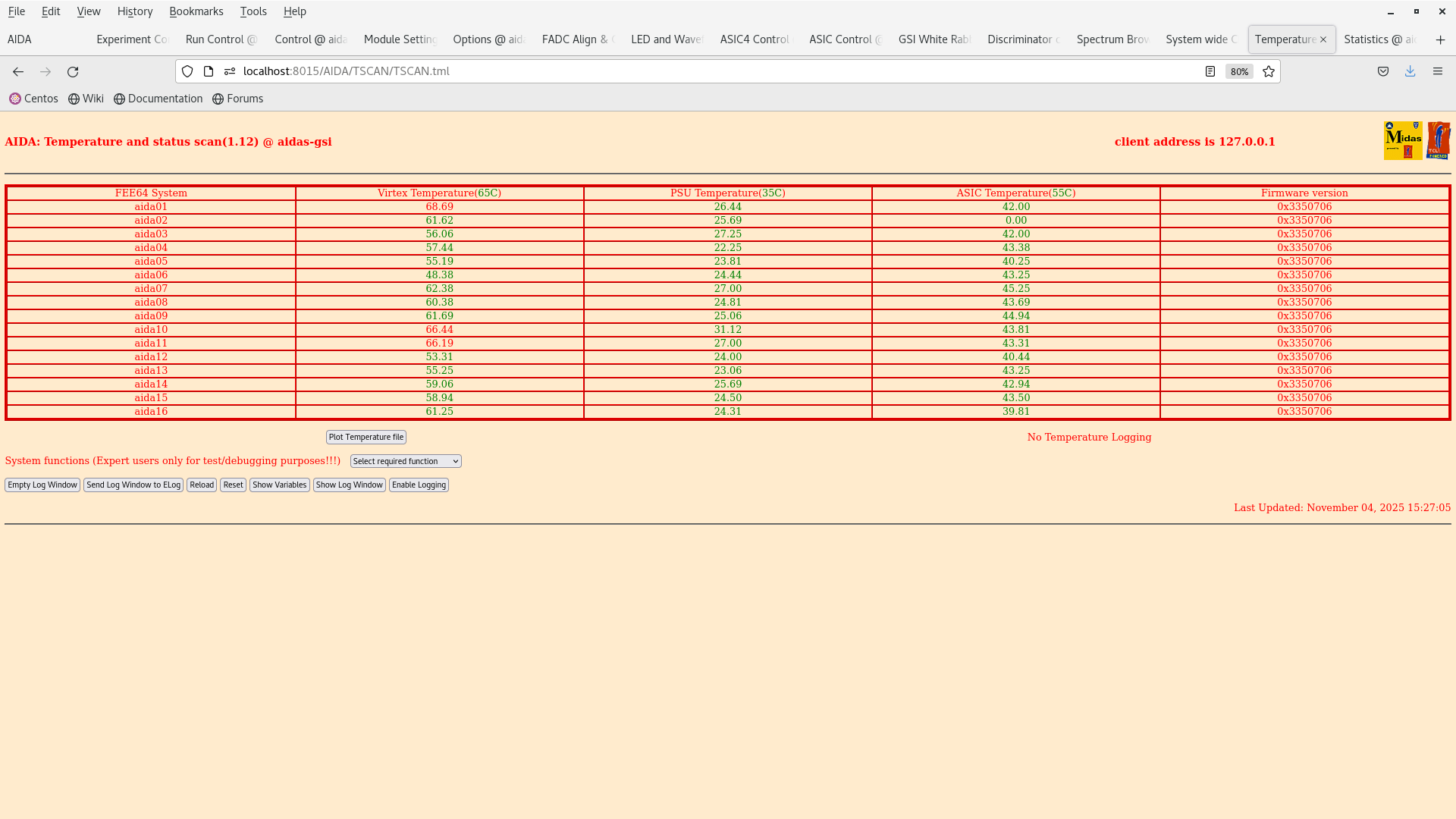
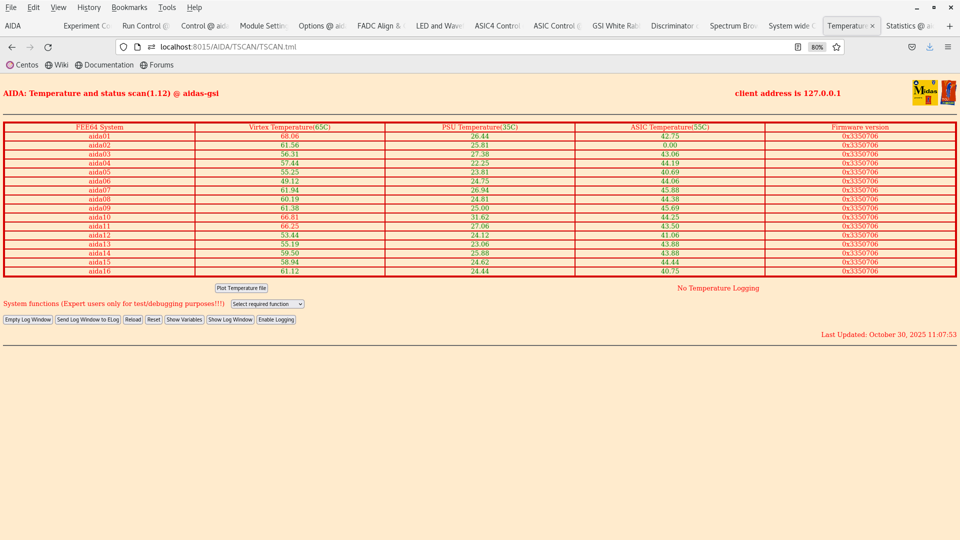
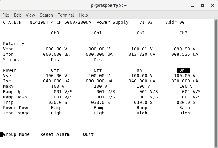
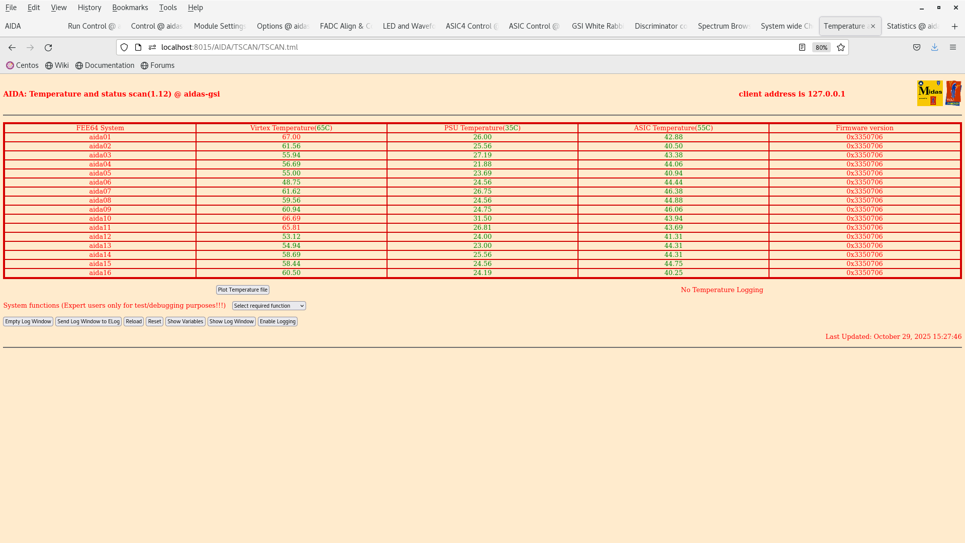
TEMPS OK. Attachment 2.

We loaded the settings from 2025Oct28-14.55.15 which has blanket thresholds of 0x64 (1 MeV) for all the ASICs.

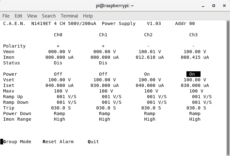
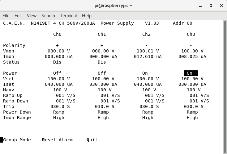
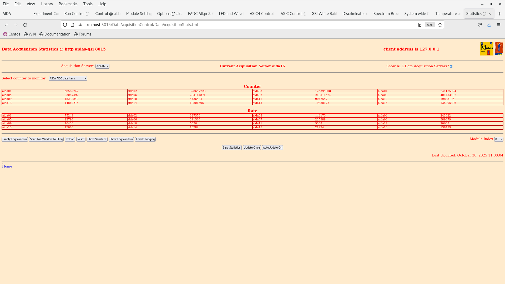
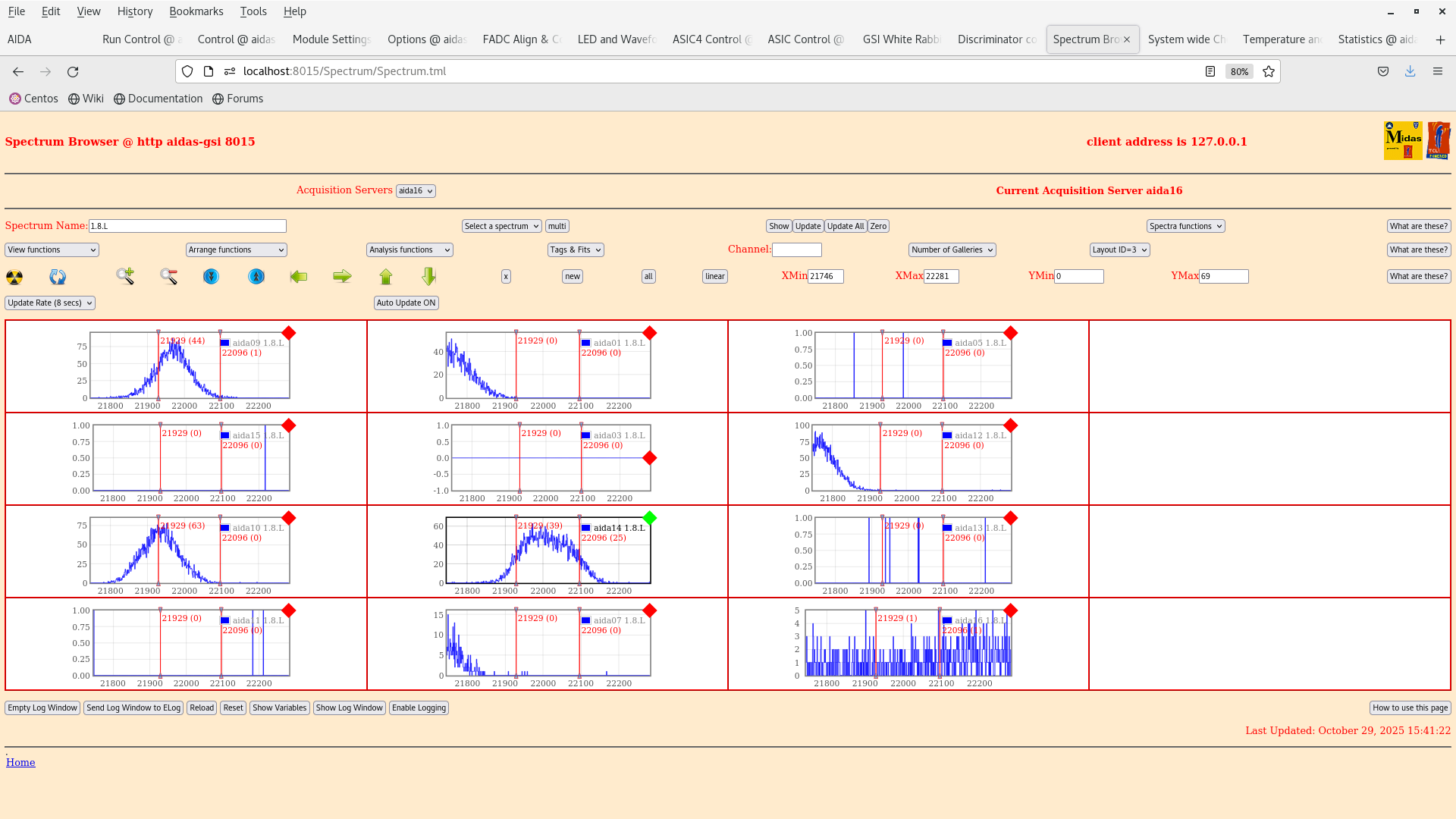
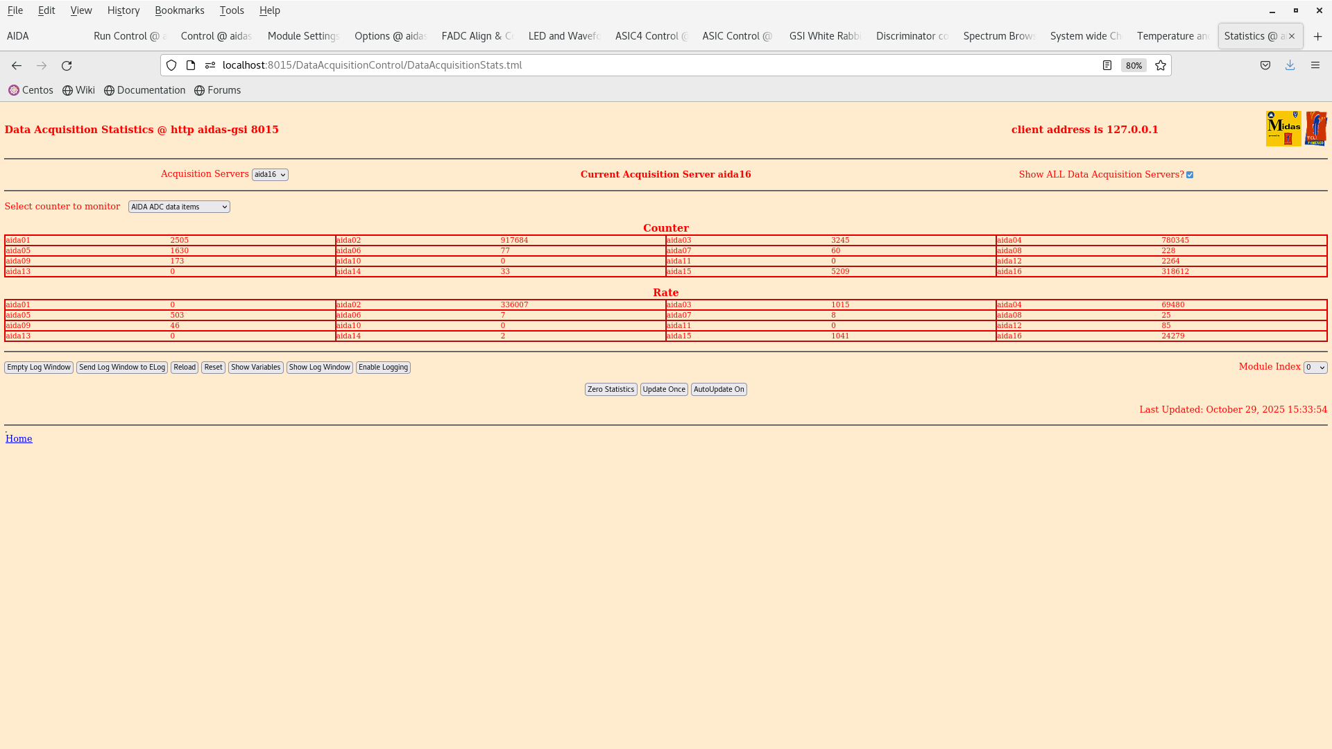
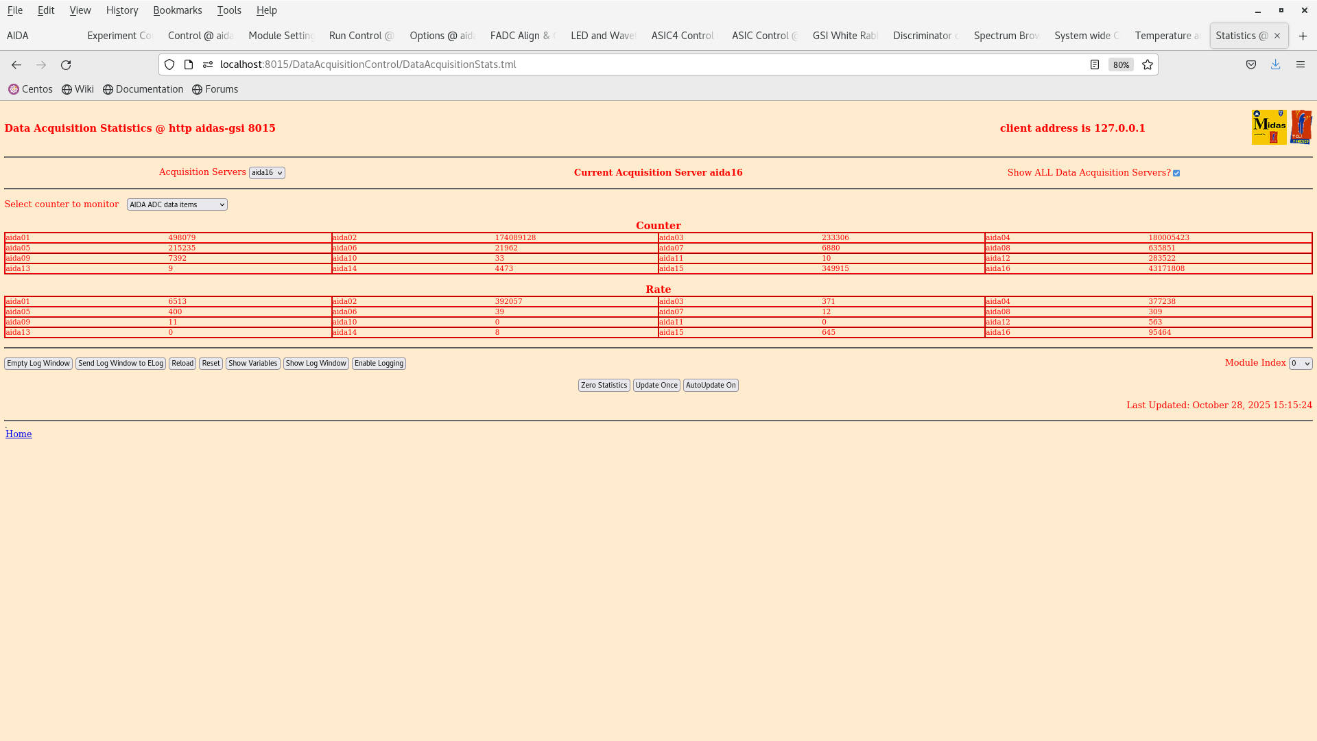
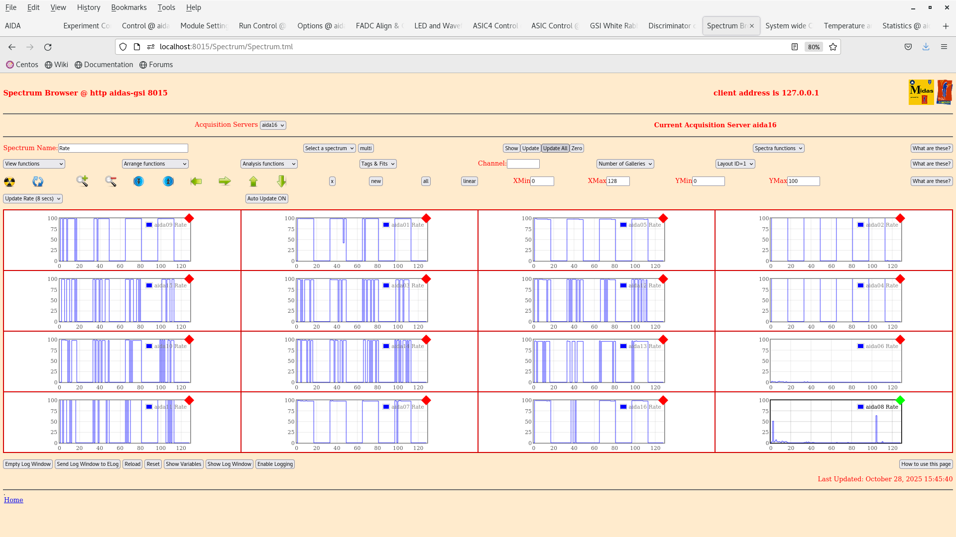
The pulser peaks seem to have gotten wider since yesterday (75 channels). We have now measured a peak width of 167 channels in aida14 (!) (attachment 3). This was only after tightening the grounding of the setup and disabling the y FEEs. Rates in the ohmic FEEs appear to have decreased by a whole order of magnitude excl. aida02 (see attachment 4).

Currently, we have the ohmic FEE64s disabled aida02,04,06,08, in the discriminator channel mask value set 0x0 ---> 0xfffffff.

15:47 We lower the thresholds to 200 keV (2025Oct29-09.55.31)to see how the system responds and what the rates are.

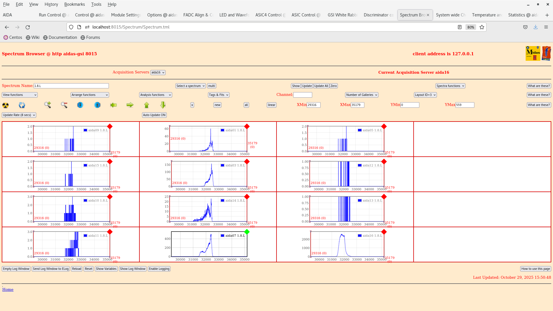
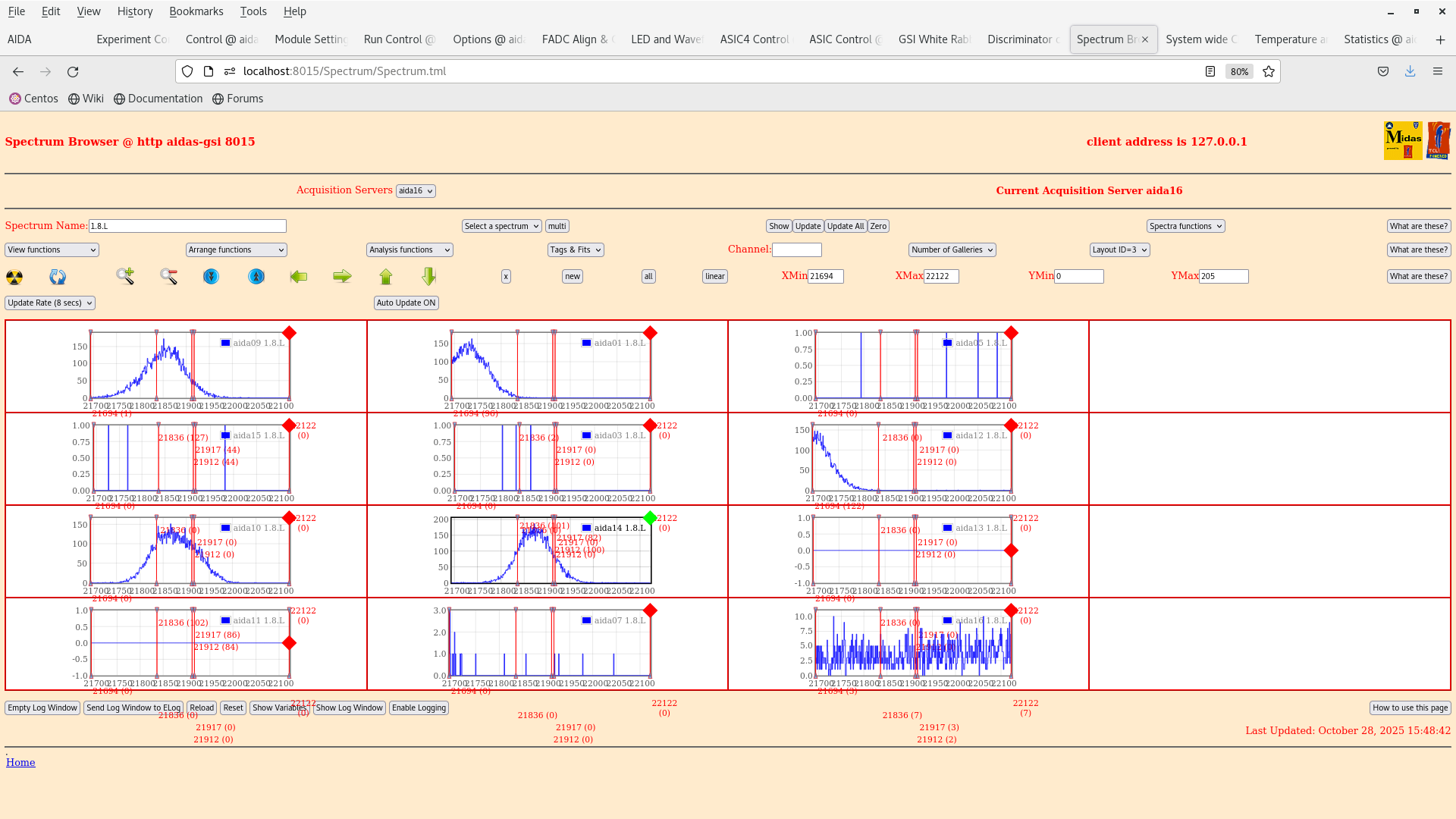
15:54 We see a 207Bi spectrum cleanly ontop of the FEE64s over which the source is place (aida01,aida14,aida03,aida07). Attachment 6. (For comparison the 207Bi spectrum obtained by Oscar Hall in the AIDA NIM paper Attachment 7).

- A quick observation is that the low energy peak around 400 keV is slightly cut off in some of the FEEs (this could suggest that the operating threshold might be slightly different in some of the FEEs).

16:00 Setting up the merger. EXPERIMENTS/AIDA/2025Oct29-16.11.06 setting made for the discriminators mask setting for the y FEEs disabled.

To the reader of this elog: By now it has taken over an hour to start up the DAQ... We give up and will try tomorrow morning |
| Attachment 1: Screenshot_from_2025-10-29_15-09-11.png
|
|
| Attachment 2: Screenshot_from_2025-10-29_15-27-50.png
|
|
| Attachment 3: Screenshot_from_2025-10-29_15-41-53.png
|
|
| Attachment 4: Screenshot_from_2025-10-29_15-34-12.png
|
|
| Attachment 5: Screenshot_from_2025-10-29_15-33-15.png
|
|
| Attachment 6: Screenshot_from_2025-10-29_15-51-38.png
|
|
| Attachment 7: Screenshot_2025-10-29_at_15-53-02_The_Advanced_Implantation_Detector_Array_(AIDA)_-_220923_AIDA_NIM_23Sept2022_pdf.png
|
_-_220923_AIDA_NIM_23Sept2022_pdf.png.png)
|
|
733
|
Wed Oct 29 13:39:13 2025 |
TD | AIDA FEE64 adaptor PCB to AIDA DSSSD cabling |
The cables from the AIDA FEE64 adaptor PCB to the MSL type BB18 DSSSDs are constructed as follows

Per FEE64

2x Samtec FFSD-17-D-xx-01-N-SR where xx is the cable length in inches
   along length if ribbon cable Al-plated copper braid drain wire with crimped eyelets to be connected to AIDA FEE64 adaptor PCB
   ribbon cables completely wrapped by inner layer of 3M 1245 copper tape (https://docs.rs-online.com/55e0/0900766b814784d5.pdf) and outer layer of 3M 5413 polyimide
tape
(https://docs.rs-online.com/2bce/A700000007254120.pdf)

1x Kapton PCB 15cm length, no screen
   transitions from 2x 34-way FTSH-134-?-L-DV-?-?-? headers to Samtec CLP-134-02-L-D connector, minimal additional material in volume around DSSSDs

Samtec information

https://suddendocs.samtec.com/catalog_english/ftsh_smt.pdf?
_gl=1*e176m0*_gcl_au*NDgyMDE2NjE1LjE3NjQyNjkxNTg.*_ga*ODU1NjkwNjU3LjE3NjQyNjkxNTg.*_ga_3KFNZC07WW*czE3NjQyNzUzOTckbzIkZzAkdDE3NjQyNzUzOTgkajU5JGwwJGgzMTY2ODMzMTQ.

https://www.samtec.com/products/ffsd-17-d-17.70-01-n

https://suddendocs.samtec.com/catalog_english/ffsd.pdf?
_gl=1*1lx9fag*_gcl_au*NDgyMDE2NjE1LjE3NjQyNjkxNTg.*_ga*ODU1NjkwNjU3LjE3NjQyNjkxNTg.*_ga_3KFNZC07WW*czE3NjQyNjkxNTckbzEkZzEkdDE3NjQyNjkzNDkkajYwJGwwJGgyMDA0NTk5MDI2

NOTE - we use FFSD-...-SR cables i.e. with strain relief

https://www.samtec.com/products/clp-134-02-l-d#catalog

https://suddendocs.samtec.com/catalog_english/clp_sm.pdf?
_gl=1*16r7foj*_gcl_au*NDgyMDE2NjE1LjE3NjQyNjkxNTg.*_ga*ODU1NjkwNjU3LjE3NjQyNjkxNTg.*_ga_3KFNZC07WW*czE3NjQyNjkxNTckbzEkZzAkdDE3NjQyNjkxNTckajYwJGwwJGgyMDA0NTk5MDI2


MSL type BB18 DSSSD pin assignments

https://www2.ph.ed.ac.uk/~td/AIDA/Information/C-2299.jpg
https://www2.ph.ed.ac.uk/~td/AIDA/Information/C-2300.jpg
https://www2.ph.ed.ac.uk/~td/AIDA/Information/C-2306.jpg

NOTE - G/R = detector bias ring

Hamamatsu 10mm x 10mm x 0.3mm PIN PDs

https://www.hamamatsu.com/content/dam/hamamatsu-photonics/sites/documents/99_SALES_LIBRARY/ssd/s3590-08_etc_kpin1052e.pdf |
|
732
|
Wed Oct 29 13:01:08 2025 |
NH | Update of AnyDesk |
AnyDesk was updated to the latest version that supports CentOS 7 (EOL OS)

First the YUM repositories were migrated, as the original address was offline due to EOL

# mv yum.repos.d yum.repos.d_old
# git clone https://github.com/tkne/centos-7-repo.git yum.repos.d

The OS was updated and a needed package was installed:

# yum update-minimal
# yum install gtkglext-libs

Finally AnyDesk was downloaded:

# https_proxy=http://proxy.gsi.de:3128 wget https://download.anydesk.com/linux/anydesk-6.3.3-1.el7.x86_64.rpm
# yum install anydesk-6.3.3-1.el7.x86_64.rpm

Note that later versions (such anydesk 6.4 or 7.0) refuse to install as CentOS 7 has too old a GLIBC
The only "fix" I observe is upgrading to a supported edition such as AlmaLinux (as used by CERN)
This would need to be coordinated with STFC |
|
731
|
Wed Oct 29 12:56:29 2025 |
TD | Further setup for 207Bi test |
Remember that 'ADC calibration' refers to the setup of the fast serial output of the AD9222 Octal, 50MSPS, 14 bit ADC which generates the waveforms - if the FEE64 is unable to calibrate all that happens is that you will not be able to see preamp output waveforms. Energy spectra will work regardless as they use a different ADC.
| Quote: |
|
Inspection of side FEEs (2,6,4,8) and possible grounding improvements:
- all screws and nuts for copper connections were tightenedFee
- FEE 6 was isolated from the copper connection grounding FEE2 with insulating tape (attachment 1)
- A piece of tape was found below FEE6 (attachments 2,3) --> shall this be removed?
Bias and power on of FEES, preparation of two settings with lower thresholds:
- note: cannot calibrate ADC of aida15 even after trying multiple times (?)
- 500-keV thresholds settings saved as EXPERIMENTS/AIDA/2025Oct29-09.49.01
- 200-keV thresholds settings saved as EXPERIMENTS/AIDA/2025Oct29-09.55.31
|
|
|
730
|
Wed Oct 29 08:12:35 2025 |
MP | Further setup for 207Bi test |
Inspection of side FEEs (2,6,4,8) and possible grounding improvements:
- all screws and nuts for copper connections were tightenedFee
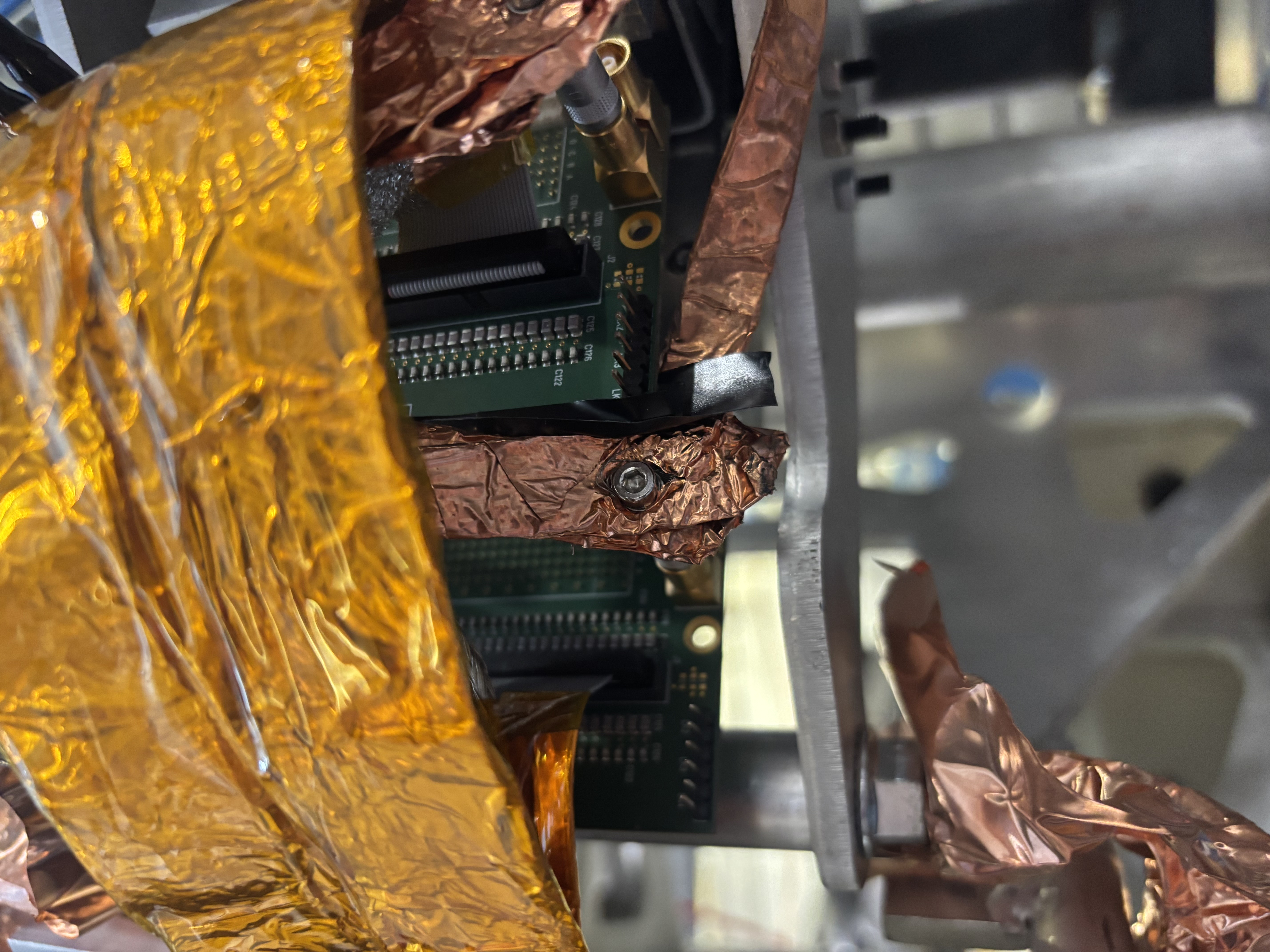
- FEE 6 was isolated from the copper connection grounding FEE2 with insulating tape (attachment 1)
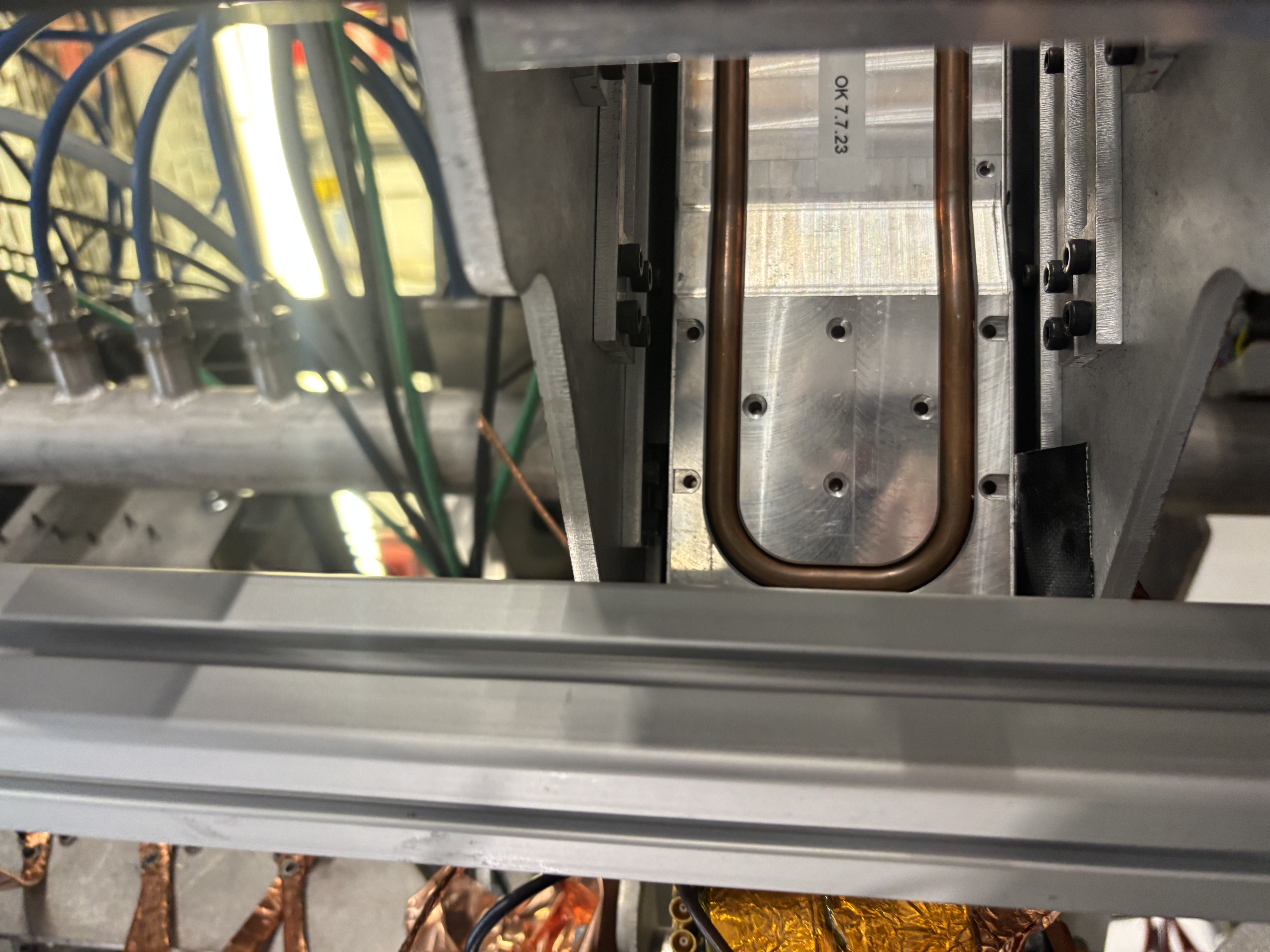
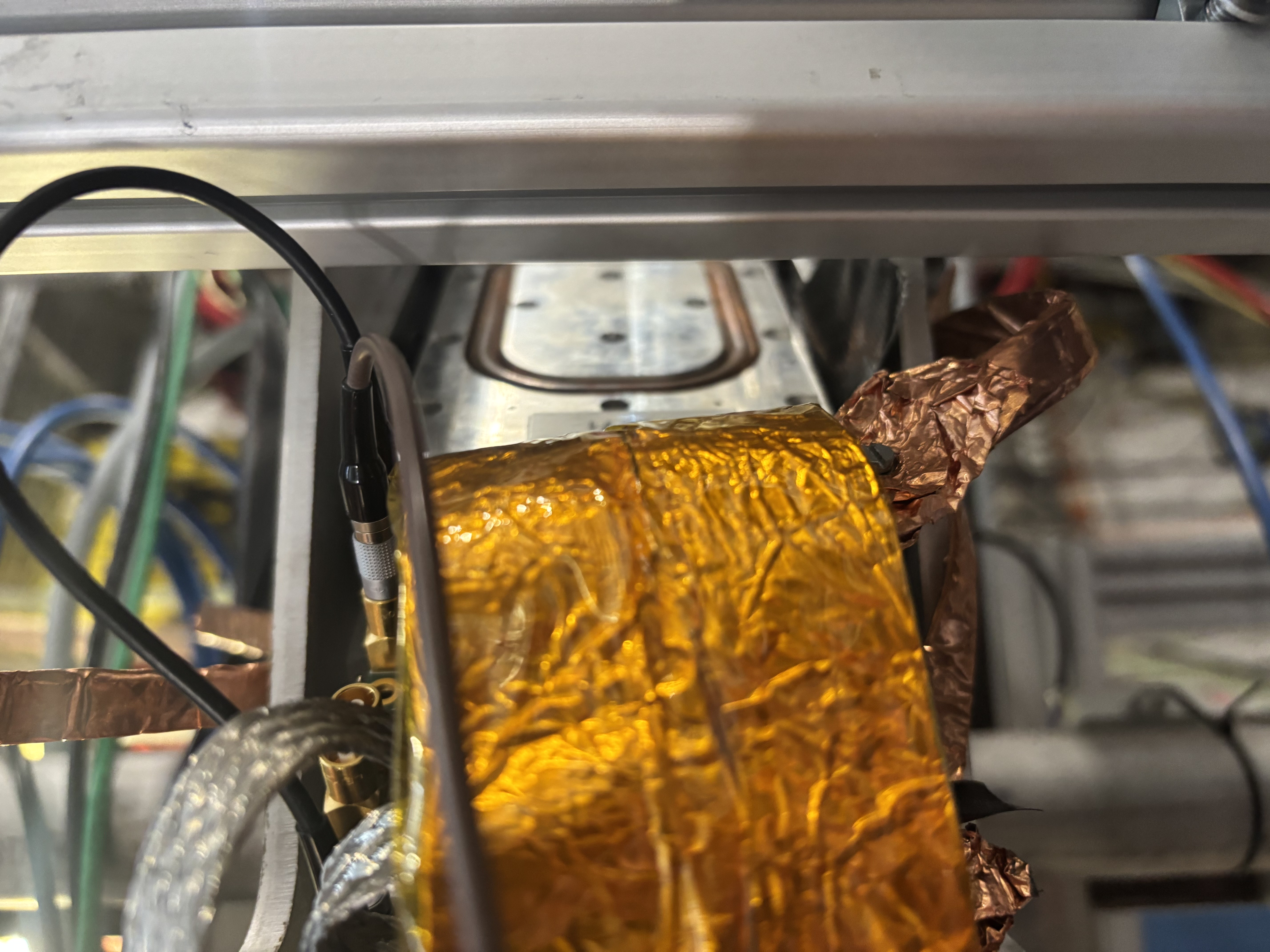
- A piece of tape was found below FEE6 (attachments 2,3) --> shall this be removed?
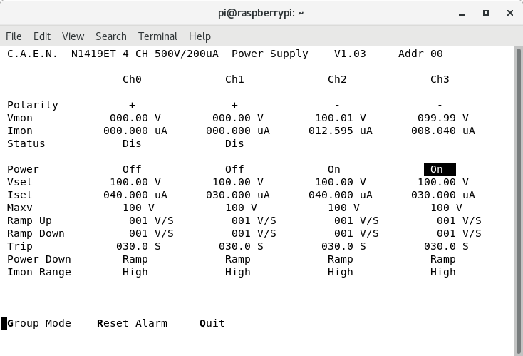
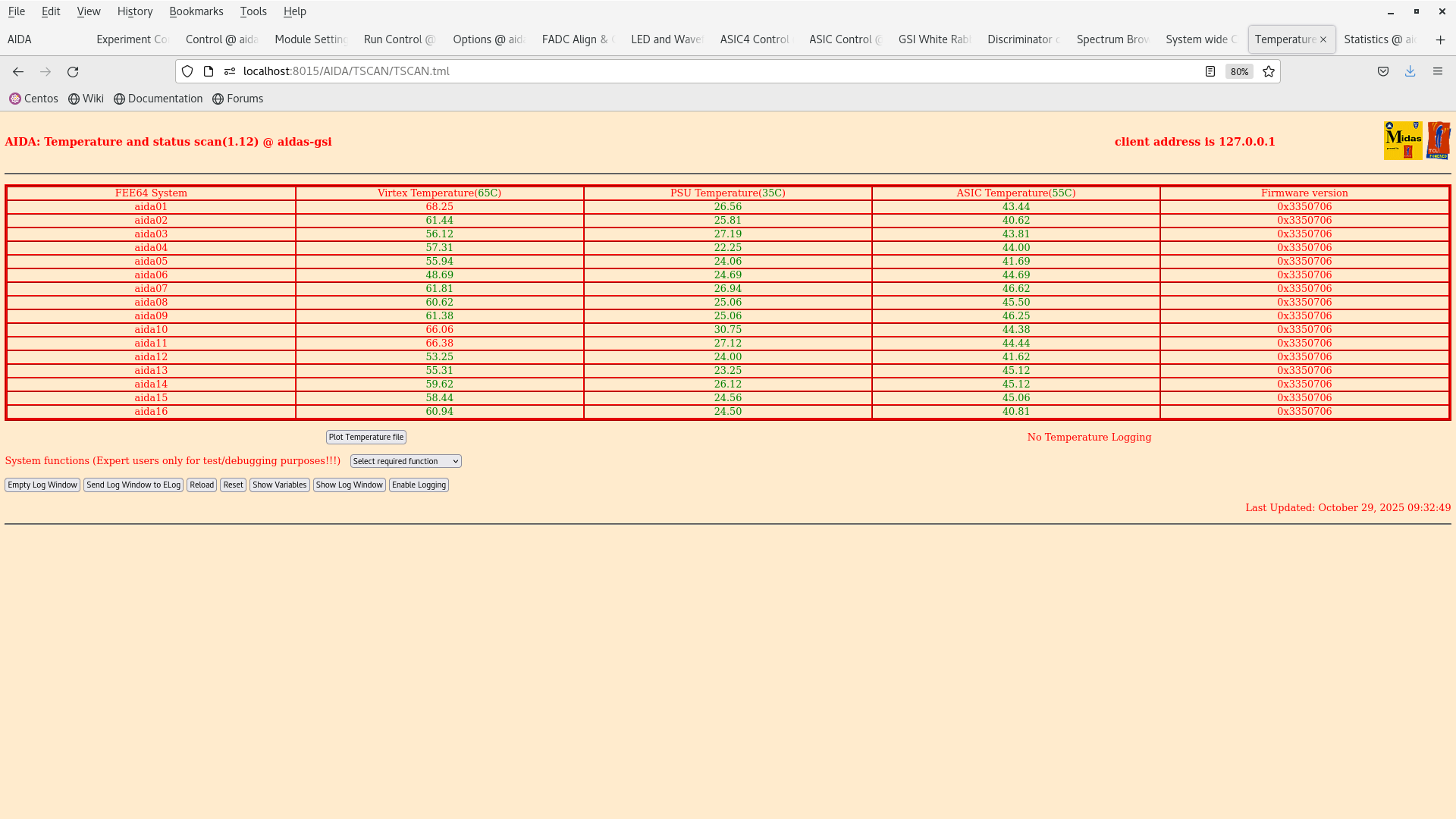
Bias and power on of FEES, preparation of two settings with lower thresholds:
- note: cannot calibrate ADC of aida15 even after trying multiple times (?)
- 500-keV thresholds settings saved as EXPERIMENTS/AIDA/2025Oct29-09.49.01
- 200-keV thresholds settings saved as EXPERIMENTS/AIDA/2025Oct29-09.55.31
|
| Attachment 1: IMG_5959.jpeg
|
|
| Attachment 2: IMG_5958.jpeg
|
|
| Attachment 3: IMG_5957.jpeg
|
|
| Attachment 4: Screenshot_from_2025-10-29_09-23-32.png
|
|
| Attachment 5: Screenshot_from_2025-10-29_09-32-52.png
|
|
|
729
|
Tue Oct 28 12:43:38 2025 |
JB, GB, MP, AM | Further setup of tests for 207Bi test |
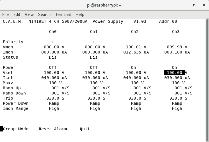
- Ch 2 and 3 of CAEN HV module changed to negative polarity, Ch 0,1 still with positive polarity
- Bias changed from the n+n to the p+n side (now Ch 2,3) - att. 1

- EXPERIMENTS/AIDA/2025Oct28-14.55.15 -> Slow comparitor -> 0x64 (1MeV) p+n Pos. bias & n+n Neg. bias

- Attachment 7: aida01 had its threshold lowered to 500 keV -> Rate increased from 500 to 6500 Hz
- Pulser inputs plugged in.


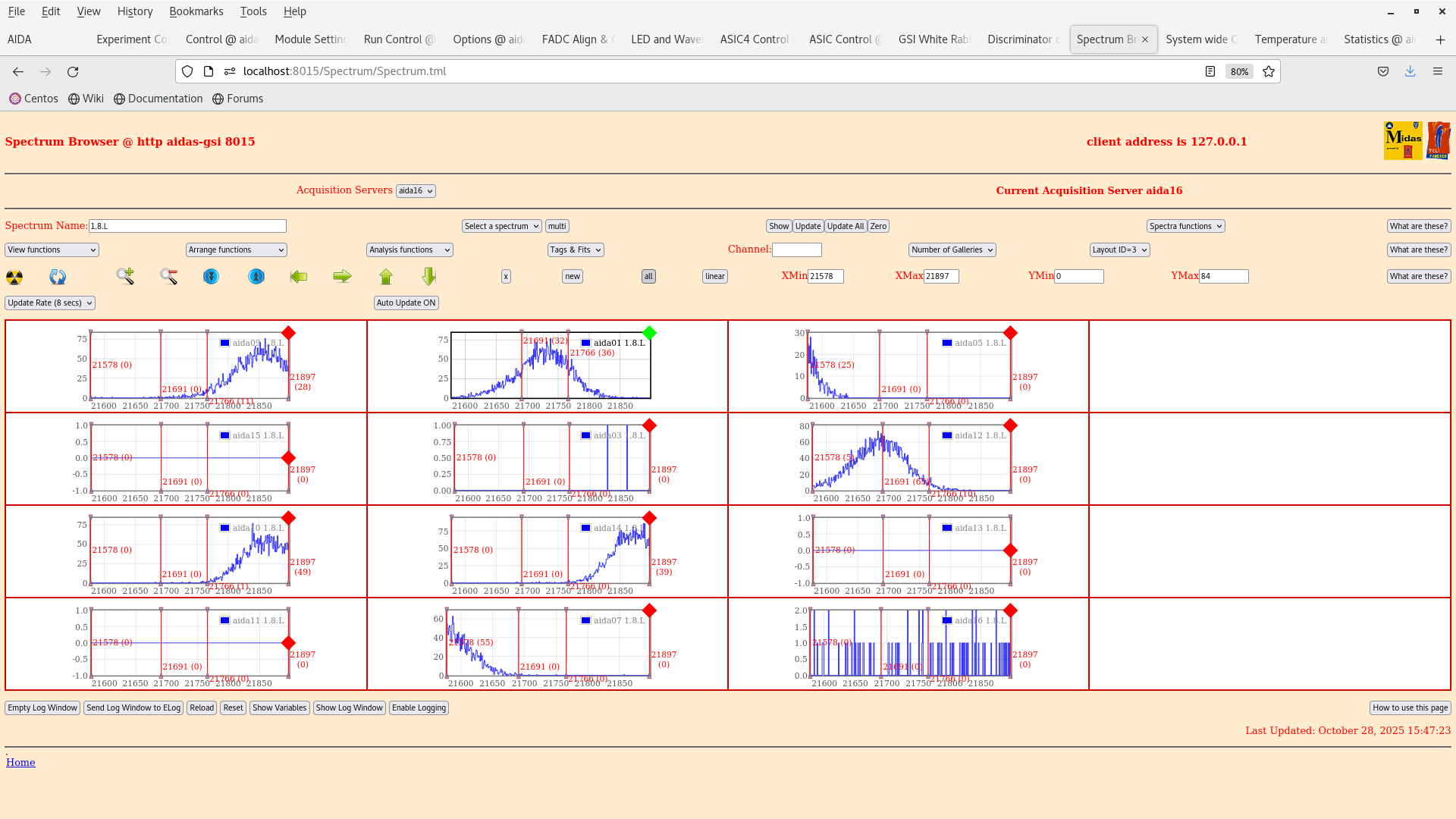
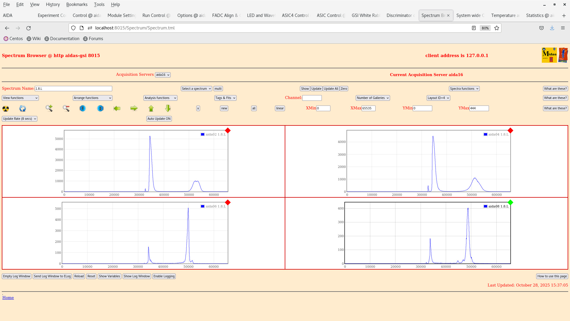
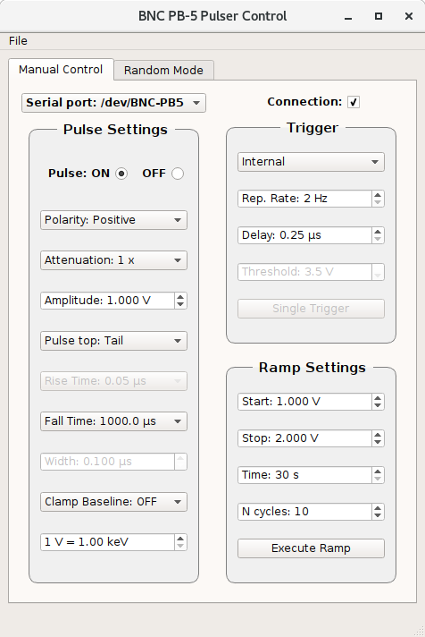
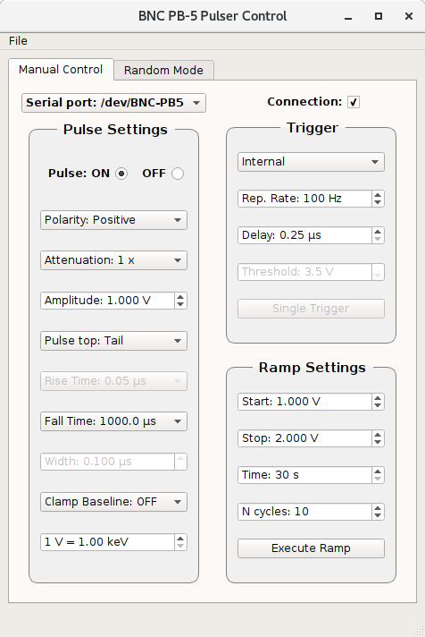
We have input a 1V pulser input into the data and have measured a peak in aida01 with a FWHM = 75 channel see attachment 9 and a FWHM in aida 14 (DSSD2) of also 76 channels which is similar to the results obtained in June from Nabil.


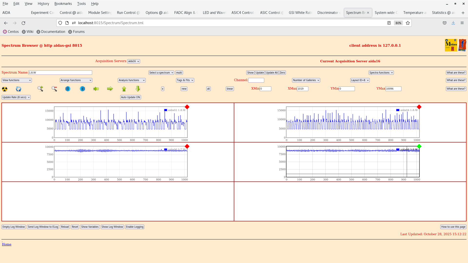
We cannot see anything from the n+n side as the signals are too noisy. Probably best to go with a higher trigger rate on the pulser and check with log scale tomorrow. It might also be worth checking the grounding on the y-strips as the problem with biasing with positive polarity is still seen in aida02 and aida04 (high noise repetition0 signal, attachment 2).

Conclusion is that we have reproduced in part the result from Nabil.

Tomorrow we will continue with the tests by lowering the thresholds and hopefully collect some data :-) |
| Attachment 1: Screenshot_from_2025-10-28_14-28-30.png
|
|
| Attachment 2: Screenshot_from_2025-10-28_15-12-27.png
|
|
| Attachment 3: Screenshot_from_2025-10-28_15-10-42.png
|
|
| Attachment 4: Screenshot_from_2025-10-28_15-09-59.png
|
|
| Attachment 5: Screenshot_from_2025-10-28_15-08-24.png
|
|
| Attachment 6: Screenshot_from_2025-10-28_15-08-02.png
|
|
| Attachment 7: Screenshot_from_2025-10-28_15-15-31.png
|
|
| Attachment 8: Screenshot_from_2025-10-28_15-49-20.png
|
|
| Attachment 9: Screenshot_from_2025-10-28_15-47-44.png
|
|
| Attachment 10: Screenshot_from_2025-10-28_15-45-44.png
|
|
| Attachment 11: Screenshot_from_2025-10-28_15-37-13.png
|
|
| Attachment 12: Screenshot_from_2025-10-28_15-31-20.png
|
|
| Attachment 13: Screenshot_from_2025-10-28_15-50-19.png
|
|
| Attachment 14: AIDA_scheme_241020525(1).png
|
.png.png)
|
|
728
|
Mon Oct 27 18:08:11 2025 |
TD | Changing ground setup from 25102025 |
19.06 Found HV OFF, DAQ GOing

      DAQ STOP
      FEE64 power OFF


> 12:55 We are going to try the follow changes to the AIDA scheme of 241012025.
>
> - Fitting LK1 (aida01, aida14), removing LK1 (aida03, aida07, aida11, aida15) - only 1x LK1 needs to be fitted per Si wafer
> - Removing LK4 to see what (if anything) changes.
>
> Check that all of the screws securing the copper foil to ground are tight - snout install/removal tends to loosen screws.
>
> - Remove the bias line between aidas 12-3-15 and aidas 16-7-11
> - Remove the test circuit
>  (These two should eliminate any extra ground path on the front, except via the DSSD)
>
> - Use a multimeter to confirm 0 Ohm between all the copper foils  (short the two probes to correct for resistance of the probe leads)
>
> - Try combinations of LK2/LK4 on the n+n fees
>
> 13:01 We check first the grounding with a multimeter and the different copper grounding components. They should all be grounded to the large iron frame, which is in
turn grounded to the platform. We also checked that the CAEN HV PSU was also grounded to the platform (it is).
>
> 13:22 We removed the LK on aida03, aida07, aida11, aida15 and added LK1 to aida01 and aida14. We try starting the DAQ and seeing the response from these changes.
>
> 13:25 We tried biasing with this configuration and the first DSSD on HV01 read a leakage current of 40 uA (too high). So we biased it down and reassessed.
>
> 13:30 It turns out we had LK1 fitted to aida04. We tried biasing again but this time DSSSD on HV01 tripped. They are fitted with LK4 so we biased down and removed
these link on aida06 and aida08.
>
> 13:35 Trying to bias now with LK4 removed from aida06 and aida08. We tried fitting and removing again. Now the setup appears to bias. This was probably due to a stray
piece of copper shielding touching the PCB.
>
> 14:22 We are checking the noise conditions now. TEMPS OK. FADC Align and whiterabbit timestamps OK.
>
> 14:30 With the changes above we have noticed an intense 5/2 ms pulsed signal in the wave forms. See attachment 2
>
> 15:20 We decabled everything and the current scheme from 24102025, see prev. elog entry is in attachment 1.
>
> 15:34 We have unbiased AIDA1 and the wave forms improve for AIDA2 (?), 5/2 ms pulsed signal is still observed in AIDA1 |
|
727
|
Mon Oct 27 11:55:00 2025 |
JB, MP, GB, NH | Changing ground setup from 25102025 |
12:55 We are going to try the follow changes to the AIDA scheme of 241012025.

- Fitting LK1 (aida01, aida14), removing LK1 (aida03, aida07, aida11, aida15) - only 1x LK1 needs to be fitted per Si wafer
- Removing LK4 to see what (if anything) changes.

Check that all of the screws securing the copper foil to ground are tight - snout install/removal tends to loosen screws.

- Remove the bias line between aidas 12-3-15 and aidas 16-7-11
- Remove the test circuit
 (These two should eliminate any extra ground path on the front, except via the DSSD)

- Use a multimeter to confirm 0 Ohm between all the copper foils  (short the two probes to correct for resistance of the probe leads)

- Try combinations of LK2/LK4 on the n+n fees

13:01 We check first the grounding with a multimeter and the different copper grounding components. They should all be grounded to the large iron frame, which is in turn grounded to the platform. We also checked that the CAEN HV PSU was also grounded to the platform (it is).

13:22 We removed the LK on aida03, aida07, aida11, aida15 and added LK1 to aida01 and aida14. We try starting the DAQ and seeing the response from these changes.

13:25 We tried biasing with this configuration and the first DSSD on HV01 read a leakage current of 40 uA (too high). So we biased it down and reassessed.

13:30 It turns out we had LK1 fitted to aida04. We tried biasing again but this time DSSSD on HV01 tripped. They are fitted with LK4 so we biased down and removed these link on aida06 and aida08.

13:35 Trying to bias now with LK4 removed from aida06 and aida08. We tried fitting and removing again. Now the setup appears to bias. This was probably due to a stray piece of copper shielding touching the PCB.

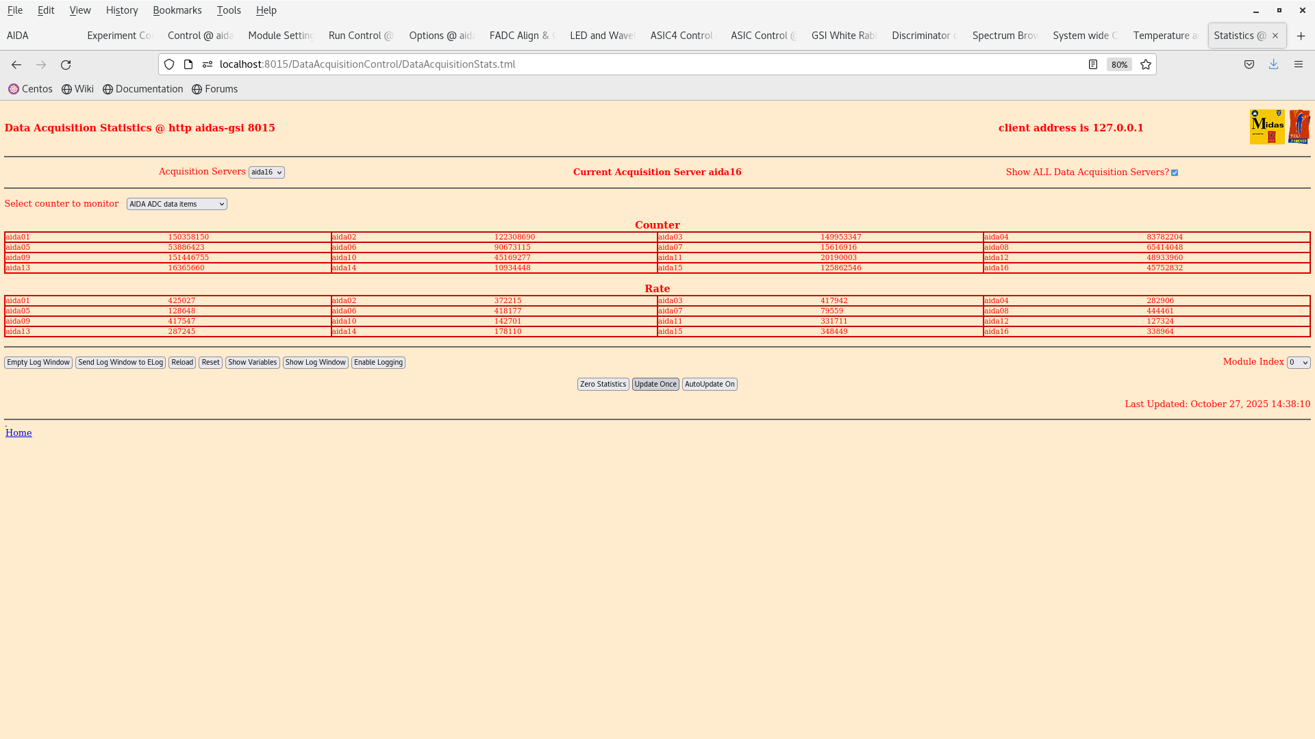
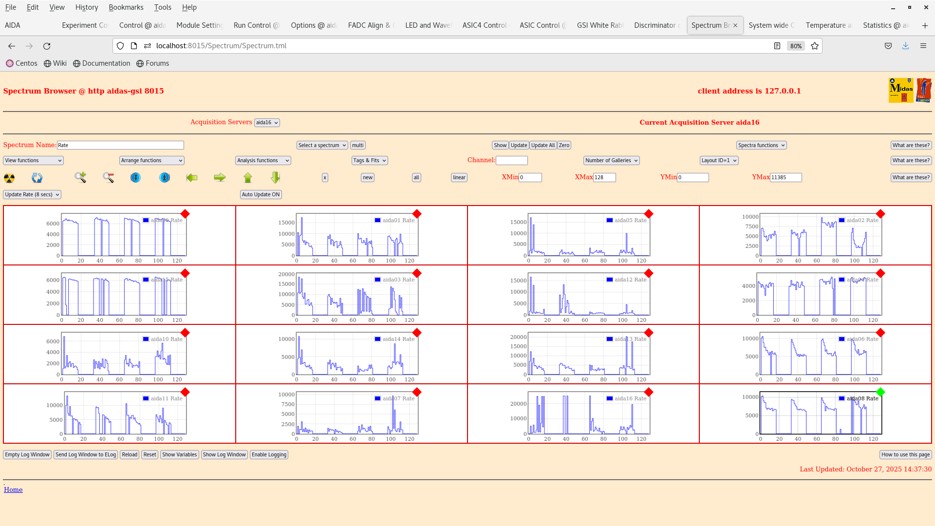
14:22 We are checking the noise conditions now. TEMPS OK. FADC Align and whiterabbit timestamps OK.

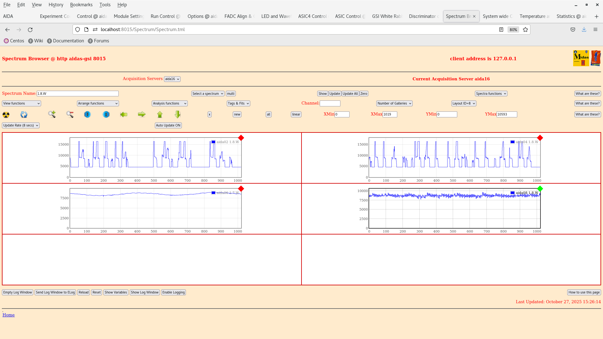
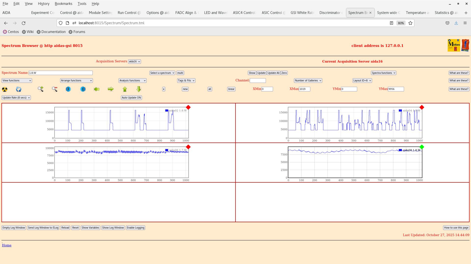
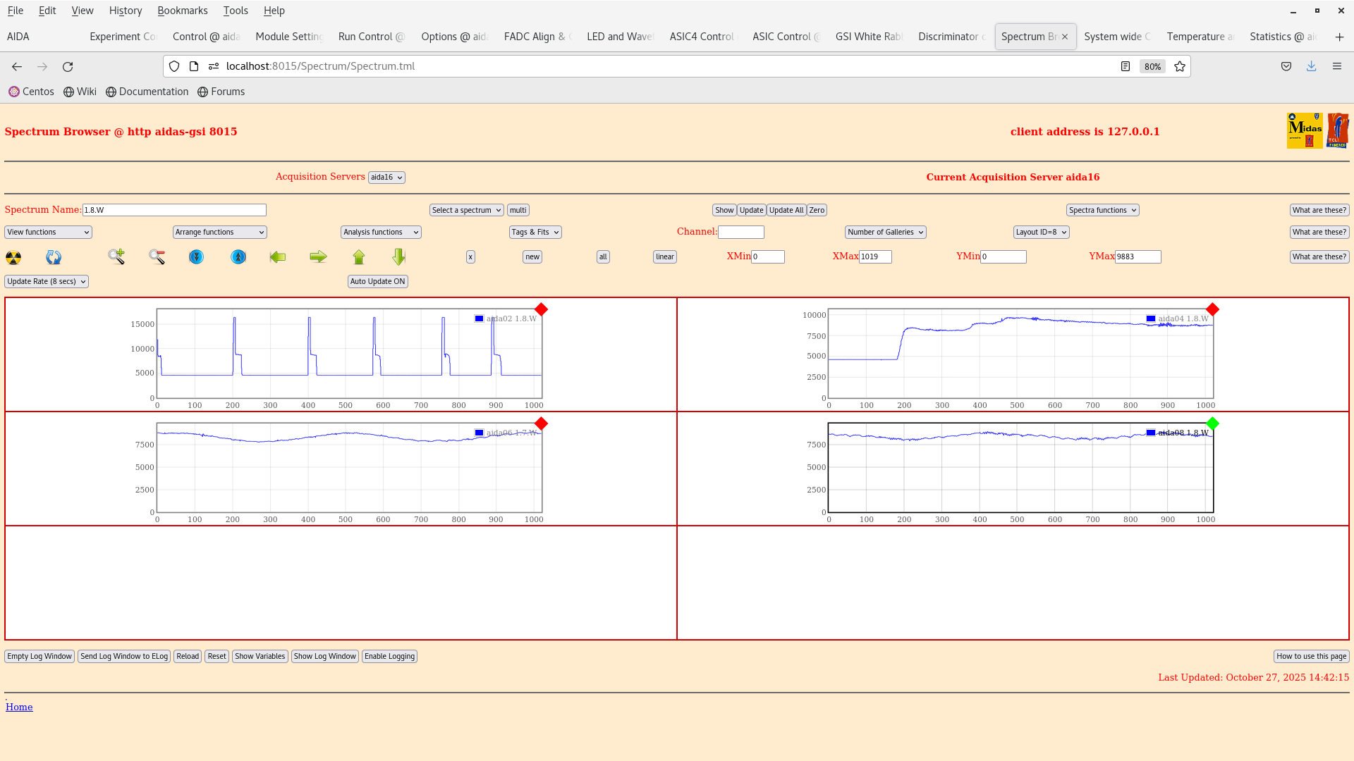
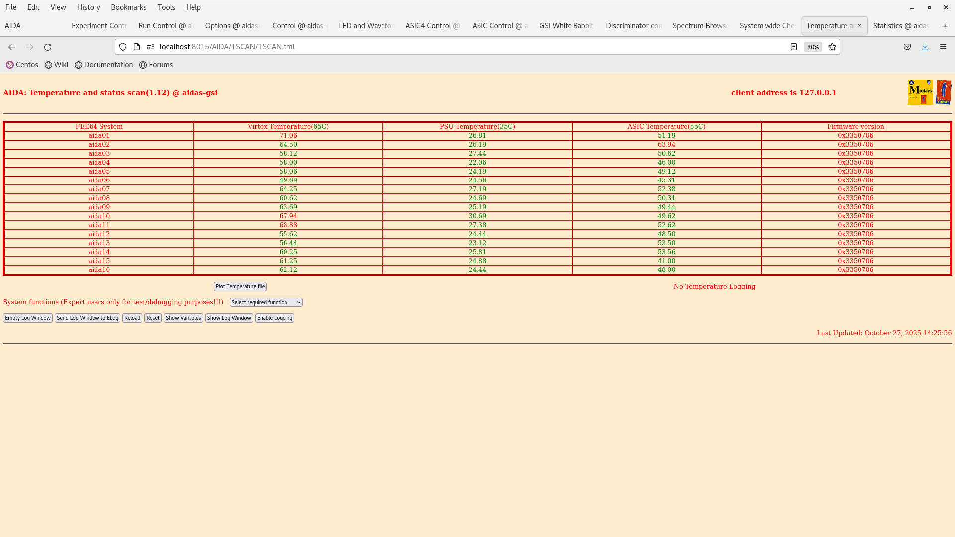
14:30 With the changes above we have noticed an intense 5/2 ms pulsed signal in the wave forms. See attachment 2

15:20 We decabled everything and the current scheme from 24102025, see prev. elog entry is in attachment 1.

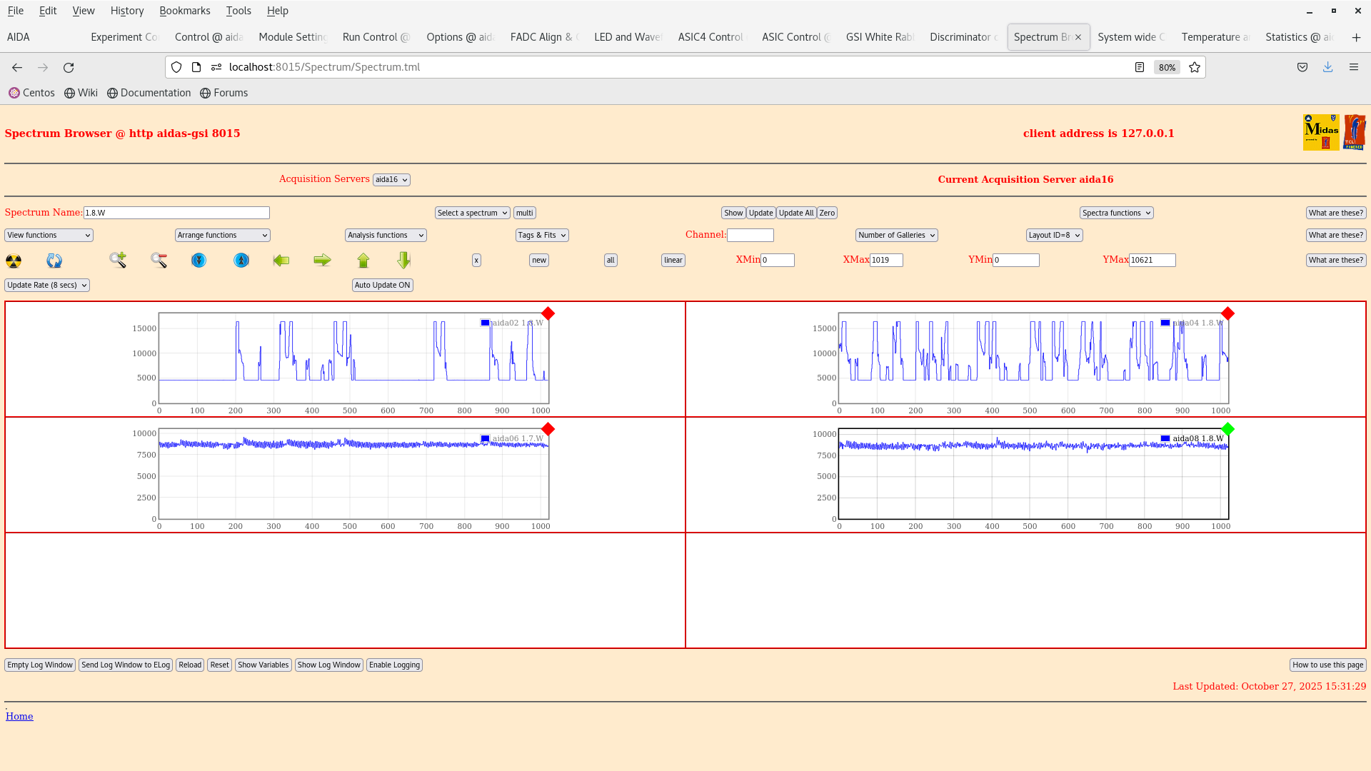
15:34 We have unbiased AIDA1 and the wave forms improve for AIDA2 (?), 5/2 ms pulsed signal is still observed in AIDA1 |
| Attachment 1: AIDA_scheme_241020525(1).png
|
.png.png)
|
| Attachment 2: Screenshot_from_2025-10-27_15-28-21.png
|
|
| Attachment 3: Screenshot_from_2025-10-27_14-44-36.png
|
|
| Attachment 4: Screenshot_from_2025-10-27_14-42-57.png
|
|
| Attachment 5: Screenshot_from_2025-10-27_14-38-24.png
|
|
| Attachment 6: Screenshot_from_2025-10-27_14-37-50.png
|
|
| Attachment 7: Screenshot_from_2025-10-27_14-26-41.png
|
|
| Attachment 8: Screenshot_from_2025-10-27_14-26-28.png
|

|
| Attachment 9: Screenshot_from_2025-10-27_15-34-01.png
|
|
|
726
|
Sun Oct 26 16:22:38 2025 |
TD | [How To] Check ASIC settings |
tcsh
cd /MIDAS/DB/EXPERIMENTS/AIDA/<ASIC settings DB key>
foreach f (`ls`)
echo $
cat "$f"/CONTENTS | grep .<ASIC parameter #>

Example

ASIC settings DB key = /MIDAS/DB/EXPERIMENTS/AIDA/2025Feb24-17.14.52
ASIC slow comparator parameter = 12

[npg@aidas-gsi 2025Feb24-17.14.52]$ tcsh
[npg@aidas-gsi 2025Feb24-17.14.52]$ cd /MIDAS/DB/EXPERIMENTS/AIDA/2025Feb24-17.14.52
[npg@aidas-gsi 2025Feb24-17.14.52]$ foreach f (`ls`)
foreach? echo $f
foreach? cat "$f"/CONTENTS | grep .12
foreach? end
aida01
ASIC.3.12 string 0x0a
ASIC.1.12 string 0x0a
ASIC.4.12 string 0x0a
ASIC.2.12 string 0x0a
aida02
ASIC.3.12 string 0x0f
ASIC.1.12 string 0x0f
ASIC.4.12 string 0x0f
ASIC.2.12 string 0x0f
aida03
ASIC.3.12 string 0x0a
ASIC.1.12 string 0x0a
ASIC.4.12 string 0x0a
ASIC.2.12 string 0x0a
aida04
ASIC.3.12 string 0x0f
ASIC.1.12 string 0x0f
ASIC.4.12 string 0x0f
ASIC.2.12 string 0x0f
aida05
ASIC.3.12 string 0x0a
ASIC.1.12 string 0x0a
ASIC.4.12 string 0x0a
ASIC.2.12 string 0x0a
aida06
ASIC.3.12 string 0xff
ASIC.1.12 string 0xff
ASIC.4.12 string 0xff
ASIC.2.12 string 0xff
aida07
ASIC.3.12 string 0xff
ASIC.1.12 string 0xff
ASIC.4.12 string 0xff
ASIC.2.12 string 0xff
aida08
ASIC.3.12 string 0xff
ASIC.1.12 string 0xff
ASIC.4.12 string 0xff
ASIC.2.12 string 0xff
aida09
ASIC.3.12 string 0x0a
ASIC.1.12 string 0x0a
ASIC.4.12 string 0x0a
ASIC.2.12 string 0x0a
aida10
ASIC.3.12 string 0x0f
ASIC.1.12 string 0x0a
ASIC.4.12 string 0x0f
ASIC.2.12 string 0x0a
aida11
ASIC.3.12 string 0xff
ASIC.1.12 string 0xff
ASIC.4.12 string 0xff
ASIC.2.12 string 0xff
aida12
ASIC.3.12 string 0x0a
ASIC.1.12 string 0x0a
ASIC.4.12 string 0x0a
ASIC.2.12 string 0x0a
aida13
ASIC.3.12 string 0xff
ASIC.1.12 string 0xff
ASIC.4.12 string 0xff
ASIC.2.12 string 0xff
aida14
ASIC.3.12 string 0xff
ASIC.1.12 string 0xff
ASIC.4.12 string 0xff
ASIC.2.12 string 0xff
aida15
ASIC.3.12 string 0x0a
ASIC.1.12 string 0x0a
ASIC.4.12 string 0x0a
ASIC.2.12 string 0x0a
aida16
ASIC.3.12 string 0xff
ASIC.1.12 string 0xff
ASIC.4.12 string 0xff
ASIC.2.12 string 0xff
CONTENTS
cat: CONTENTS/CONTENTS: Not a directory

Recommend saving (and recording ASIC settings DB key) with specific slow comparator settings which can be subsequently restored.
For example

- slow comparator p+n FEE64s 0xa, n+n FEE64s 0xf
- all slow comparators 0x64
etc |
|
725
|
Fri Oct 24 14:33:37 2025 |
JB, GB, MP, AM | Snout grounding, bias and test input layout as of 24.10.2025 |
|
| Attachment 1: AIDA_scheme_241020525(2).pdf
|
-0.png)
|
|
724
|
Fri Oct 24 12:29:02 2025 |
JB, GB, MP, AM, NH | 207Bi source threshold tests |
> > >
> > > We have dismounted the AIDA stack and bPlast and realigned the cables so that they can fit into the adapters.
> > >
> > > The plan for the next couple days is the following:
> > >
> > > - Alignment -- done
> > > - Remount cable -- done
> > > - Fix position w/o bPlast mounted -- done
> > > - Remount bracket for the last stage -- done
> > > - Remount AIDA 1 & 2 and the 207Bi source with the source holder -- done
> > > - Mount the snout and take data -- we wait till next week Monday when the heat exchanger is active again. (ongoing)
> > >
> > > The current setup at the end of work is that the snout is mount with a bPlast (uncabled) and 2 AIDA layers at the regular spaced position with a 207Bi source down stream, as can be seen in the previous elog. The source is ~1 cm away from the middle AIDA wafer.
> > >
> > > Currently what is cabled:
> > >
> > > - Signal out from the detector
> > > - Bias daisy chain
> > >
> > > Still to be cabled:
> > >
> > > - HV cable
> > > - Grounding
> > > - Pulser
> > >
> > > Additional info on the source position:
> > > - the source is at ~9.6 mm distance from the downstream detector
> > > - the source is placed at the centre of the middle wafer: 12.25 cm in x, 4.75 cm in y
> > > - the radius of the source is ~1.5 mm
> >
> > The Messhuette has been cleaned and equipment has been rearranged. If there are any broken or missing components be sure to follow up with the FRS group (as I believe they have been cleaning here).
> >
> > We are resuming the work on the source measurements as the cooling water is back. Some of the valves still look closed so we are investigating if the water is flowing to the setup.
> >
> > 14:31 Temperature on start up OK - attachment 2.
> >
> > 15:41 We reset the ASIC control registers to a setup used in Feb 2024 (2025Feb24-17.14.52) to match the full AIDA setup (it was using BB7 initially in aida10).
> >
> > The old bias scheme is obsolete and the bias is now done via the Ohmic side.
> >
> > 16:47 We have look at some initial spectra with the 207Bi 3-8 shows the ADC channels and waveforms of the n+n and p+n sides. Bias and grounding developed by Nabiel have been done.
> >
> > We are going to wait for the system to stabilise over night so that we start taking data tomorrow. Then we can analyse the results and see what we get :) Some channels are clearly broken which can be seen in the waveforms eg. aida16.
>
> 11:31 The detector was turned off last night to put it into a safe state. We return to make some comparison of the noise w.r.t the tests performed by Nabil and co.
>
> email snippet:
>
> "
> I would suggest that you first quantify current noise performance (slow comparators -> 0x64 to reduce rate, measure pulser peak width) for each FEE64 (use layouts 3 and 4) and compare to Nabil's most recent test results. Looking at last night's 1.8.W spectra I would assume that they would be significantly worse but best to check.
>
> I would then suggest you carefully check
>
>     Grounding configuration (both internal and external to the snout) used Nabil's most recent tests has actually been re-established
>     Grounding of the bPlas cabling
> "
>
> We are going to restart the DAQ and set the LEC thresholds to 0x64 and compare the peak FWHM with a pulser.
>
> 11:50 We started up the DAQ temps and bias look OK.
>
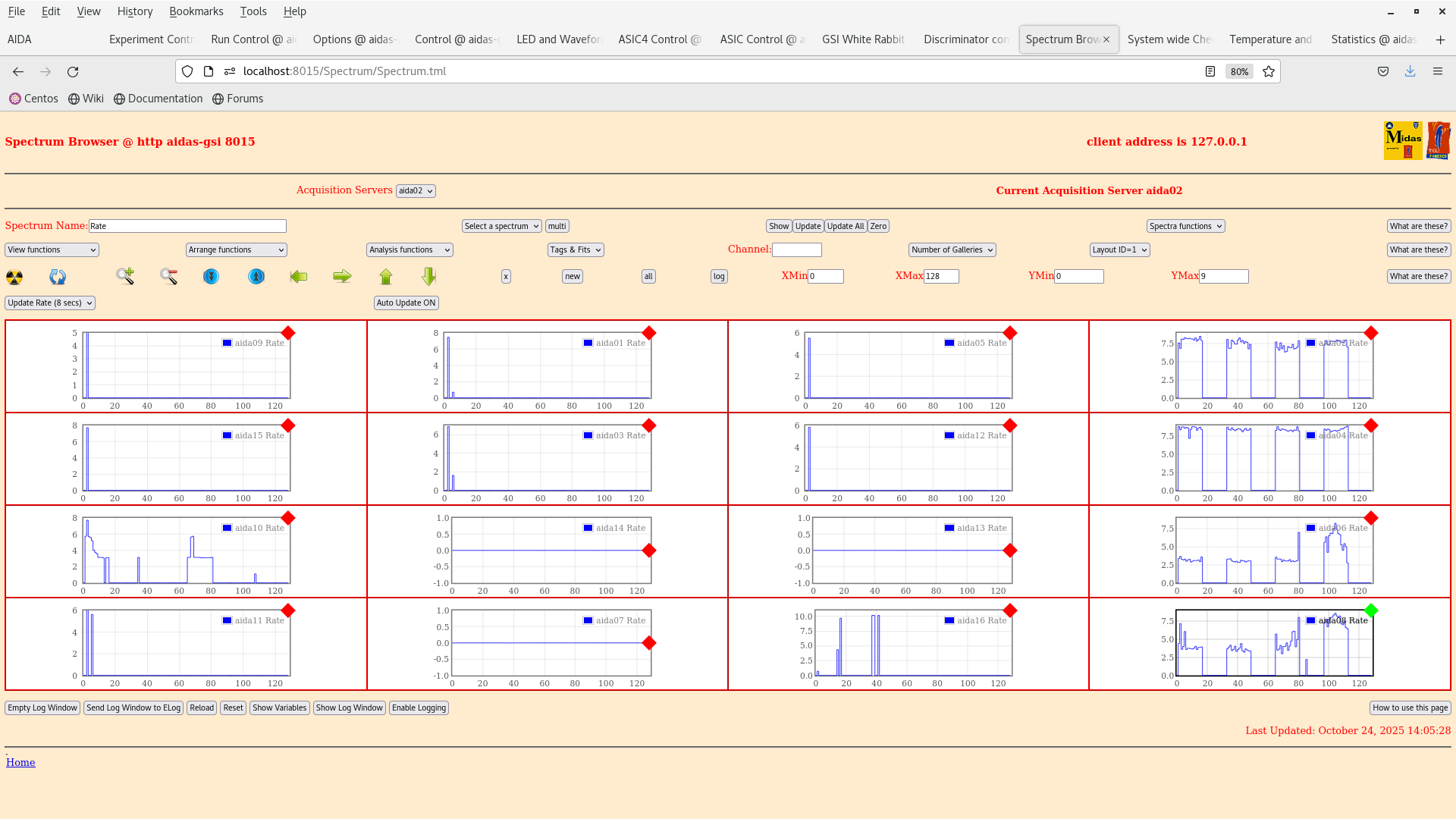
> 12:00 We set the thresholds on each ASIC in the slow comparator LEC to 0x64. This should correspond to a high threshold. For some reason the y-strips are still noisy (wrong polarity in the register ?)

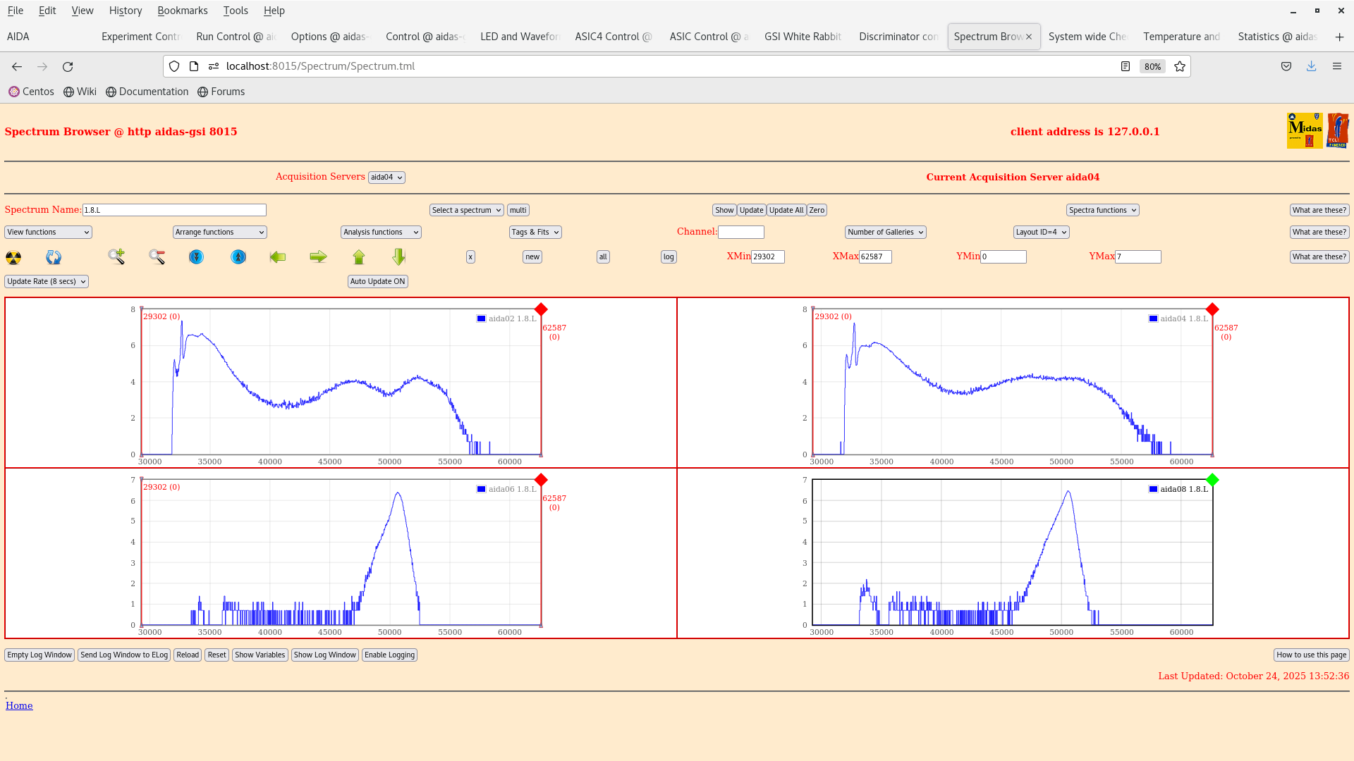
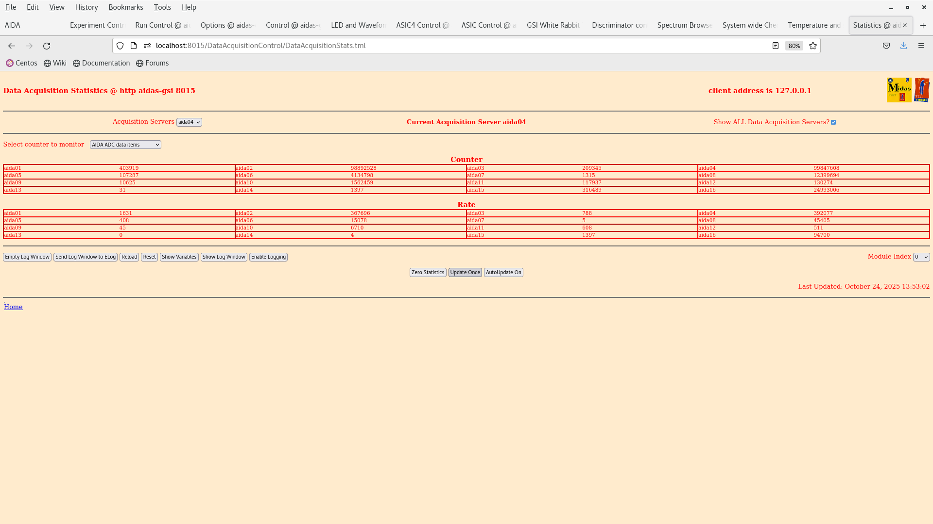
13:28 we returned after a hearty lunch. When turning on the FEE64s we noticed that the bias of the CAEN to the detector increases by 0.3 V.

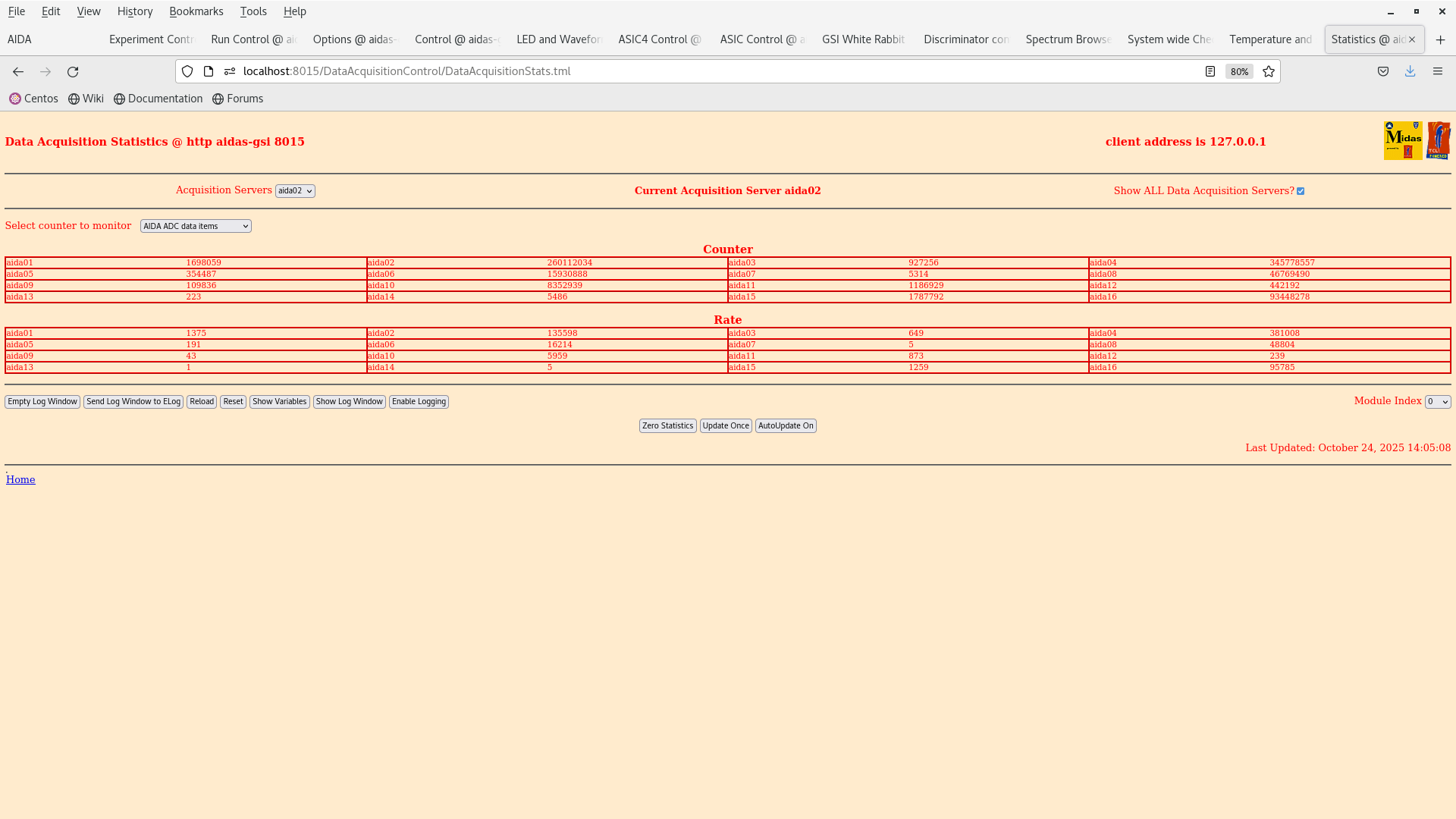
We rebiased and set the thresholds in one FEE64 aida02 to 0xff (very high, attachment 2) and the detector is still reading about 100 kHz ADC items. When the threshold was set to 0x64 it was 360 kHz (attachment 4).

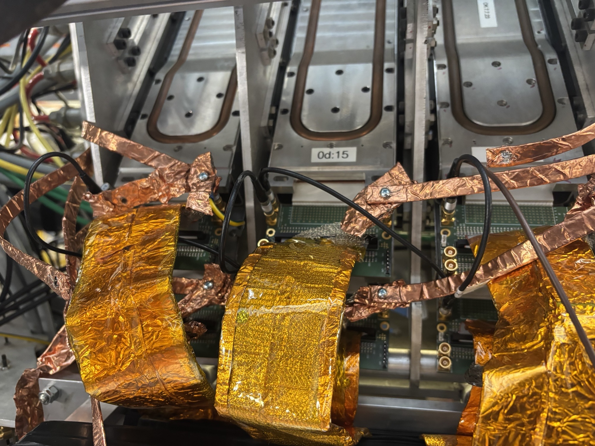
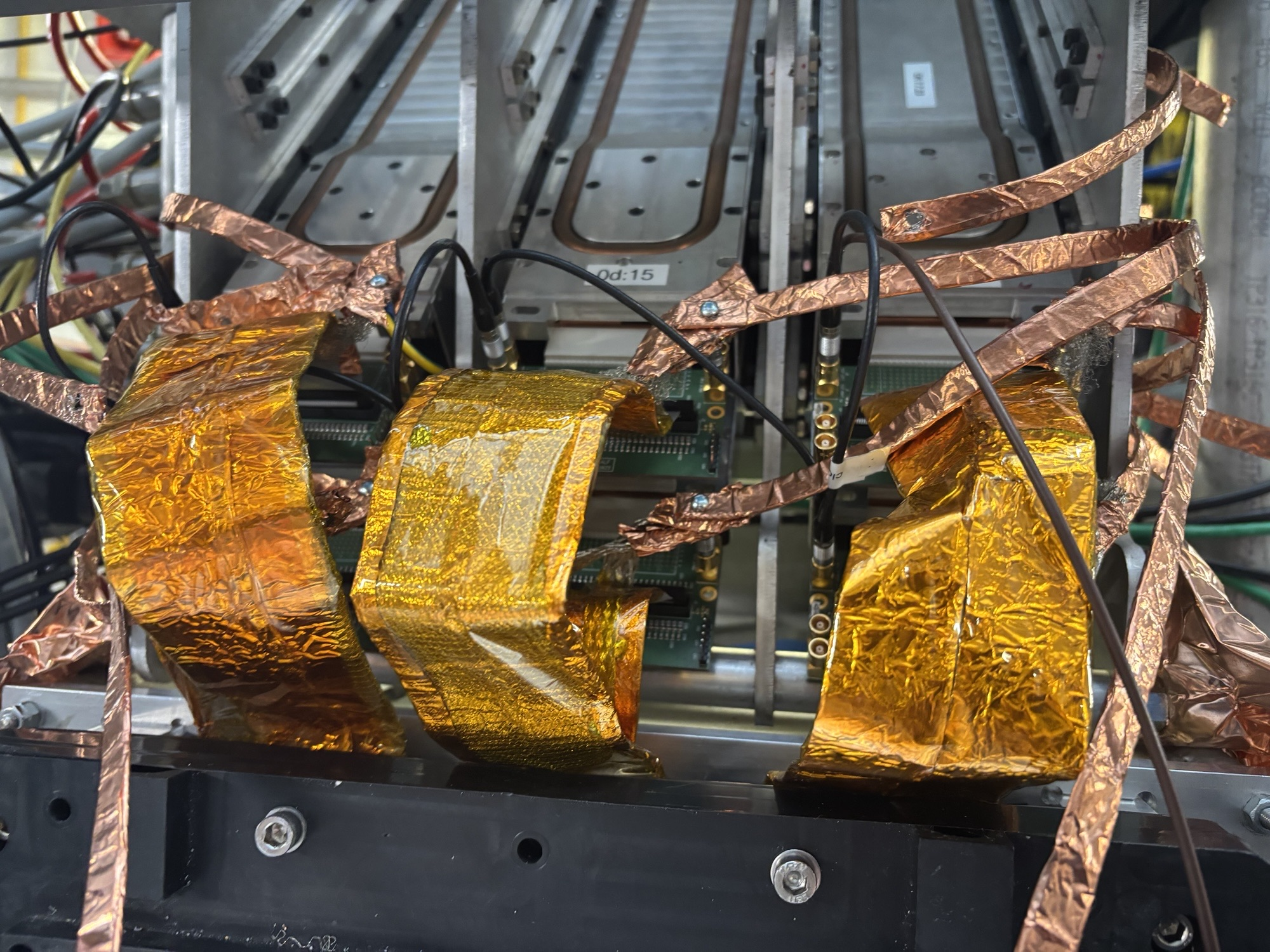
We bias down the system to cross-check the cabling etc. |
| Attachment 1: Screenshot_from_2025-10-24_13-52-42.png
|
|
| Attachment 2: Screenshot_from_2025-10-24_13-53-05.png
|
|
| Attachment 3: Screenshot_from_2025-10-24_14-08-56.png
|
|
| Attachment 4: Screenshot_from_2025-10-24_14-08-52.png
|
|
| Attachment 5: IMG_5919.jpeg
|
|
| Attachment 6: IMG_5918.jpeg
|
|
| Attachment 7: IMG_5917.jpeg
|
|
| Attachment 8: IMG_5914.jpeg
|
|
| Attachment 9: IMG_5913.jpeg
|
|
| Attachment 10: IMG_5915.jpeg
|
|
| Attachment 11: IMG_5916.jpeg
|
|
|
723
|
Fri Oct 24 10:31:59 2025 |
JB, GB, MP, AM, NH | 207Bi source threshold tests |
> >
> > We have dismounted the AIDA stack and bPlast and realigned the cables so that they can fit into the adapters.
> >
> > The plan for the next couple days is the following:
> >
> > - Alignment -- done
> > - Remount cable -- done
> > - Fix position w/o bPlast mounted -- done
> > - Remount bracket for the last stage -- done
> > - Remount AIDA 1 & 2 and the 207Bi source with the source holder -- done
> > - Mount the snout and take data -- we wait till next week Monday when the heat exchanger is active again. (ongoing)
> >
> > The current setup at the end of work is that the snout is mount with a bPlast (uncabled) and 2 AIDA layers at the regular spaced position with a 207Bi source down stream, as can be seen in the previous elog. The source is ~1 cm away from the middle AIDA wafer.
> >
> > Currently what is cabled:
> >
> > - Signal out from the detector
> > - Bias daisy chain
> >
> > Still to be cabled:
> >
> > - HV cable
> > - Grounding
> > - Pulser
> >
> > Additional info on the source position:
> > - the source is at ~9.6 mm distance from the downstream detector
> > - the source is placed at the centre of the middle wafer: 12.25 cm in x, 4.75 cm in y
> > - the radius of the source is ~1.5 mm
>
> The Messhuette has been cleaned and equipment has been rearranged. If there are any broken or missing components be sure to follow up with the FRS group (as I believe they have been cleaning here).
>
> We are resuming the work on the source measurements as the cooling water is back. Some of the valves still look closed so we are investigating if the water is flowing to the setup.
>
> 14:31 Temperature on start up OK - attachment 2.
>
> 15:41 We reset the ASIC control registers to a setup used in Feb 2024 (2025Feb24-17.14.52) to match the full AIDA setup (it was using BB7 initially in aida10).
>
> The old bias scheme is obsolete and the bias is now done via the Ohmic side.
>
> 16:47 We have look at some initial spectra with the 207Bi 3-8 shows the ADC channels and waveforms of the n+n and p+n sides. Bias and grounding developed by Nabiel have been done.
>
> We are going to wait for the system to stabilise over night so that we start taking data tomorrow. Then we can analyse the results and see what we get :) Some channels are clearly broken which can be seen in the waveforms eg. aida16.

11:31 The detector was turned off last night to put it into a safe state. We return to make some comparison of the noise w.r.t the tests performed by Nabil and co.

email snippet:

"
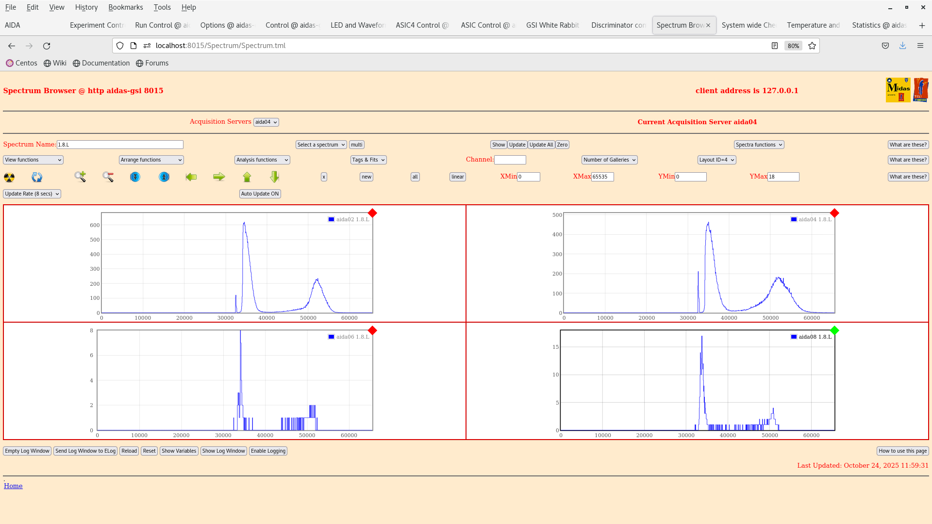
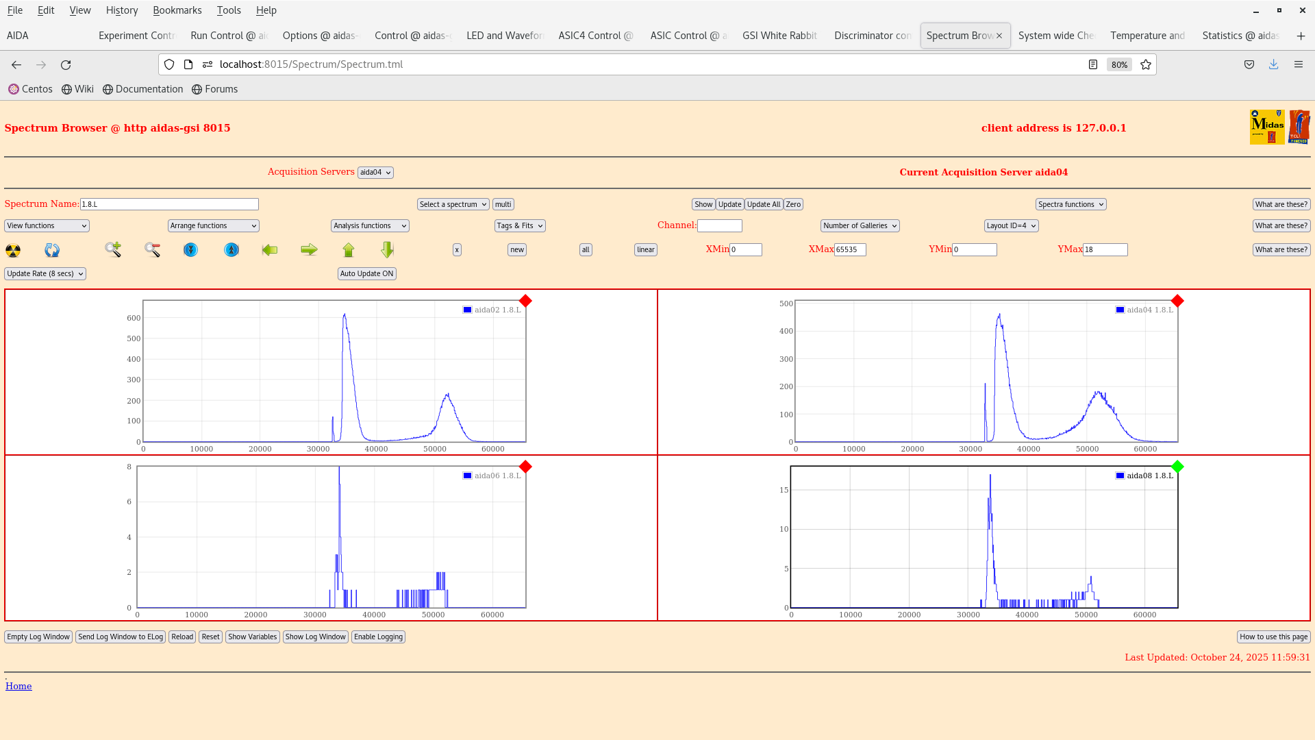
I would suggest that you first quantify current noise performance (slow comparators -> 0x64 to reduce rate, measure pulser peak width) for each FEE64 (use layouts 3 and 4) and compare to Nabil's most recent test results. Looking at last night's 1.8.W spectra I would assume that they would be significantly worse but best to check.

I would then suggest you carefully check

    Grounding configuration (both internal and external to the snout) used Nabil's most recent tests has actually been re-established
    Grounding of the bPlas cabling
"

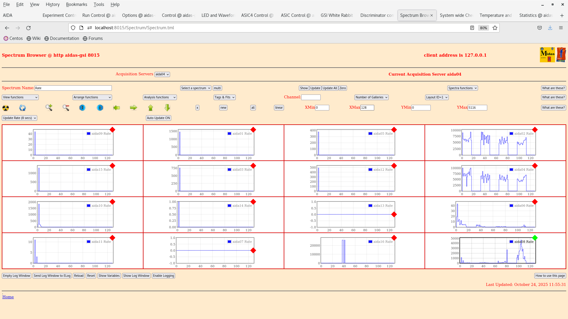
We are going to restart the DAQ and set the LEC thresholds to 0x64 and compare the peak FWHM with a pulser.

11:50 We started up the DAQ temps and bias look OK.

12:00 We set the thresholds on each ASIC in the slow comparator LEC to 0x64. This should correspond to a high threshold. For some reason the y-strips are still noisy (wrong polarity in the register ?) |
| Attachment 1: Screenshot_from_2025-10-24_11-56-06.png
|
|
| Attachment 2: Screenshot_from_2025-10-24_12-00-30.png
|
|
| Attachment 3: Screenshot_from_2025-10-24_11-59-35.png
|
|
| Attachment 4: Screenshot_from_2025-10-24_11-55-02.png
|
|
| Attachment 5: Screenshot_from_2025-10-24_11-54-09.png
|
|
| Attachment 6: Screenshot_from_2025-10-24_11-53-59.png
|
|
|
722
|
Thu Oct 23 18:45:12 2025 |
TD | Thursday 23 October 2025 |
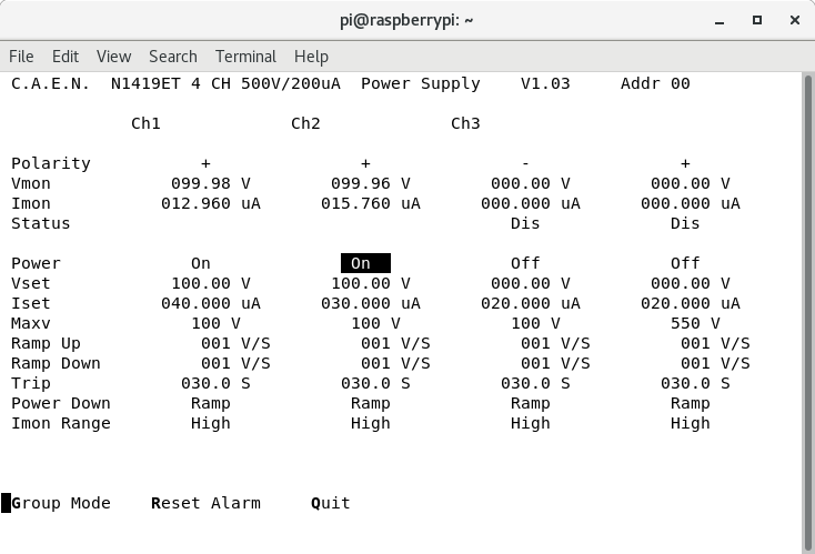
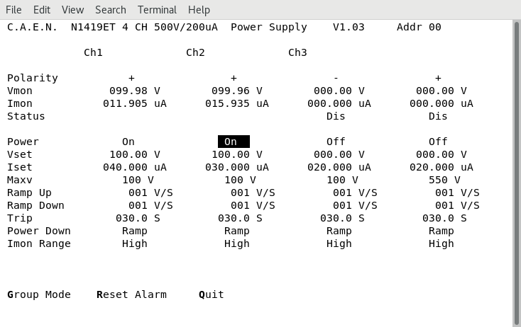
19.45 Remote system check

      DSSSD bias & leakage currents OK - attachment 1

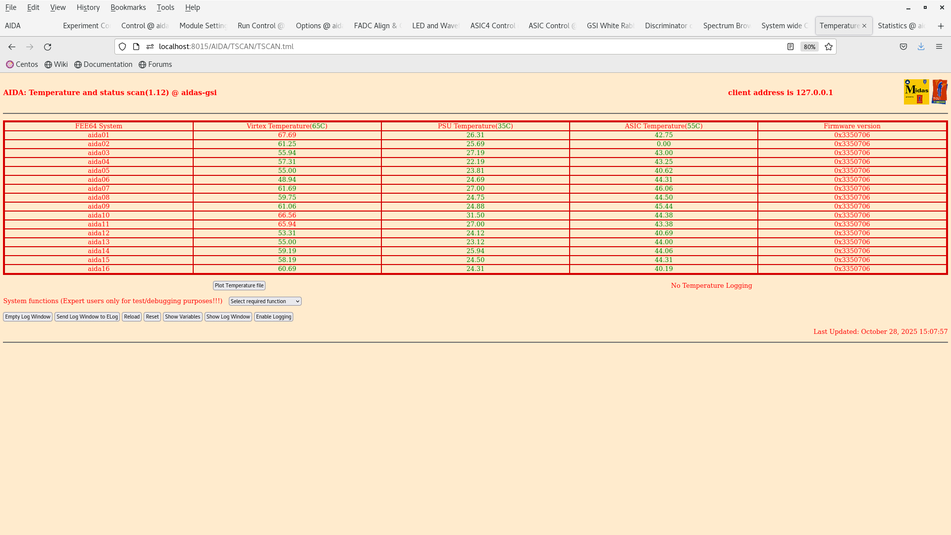
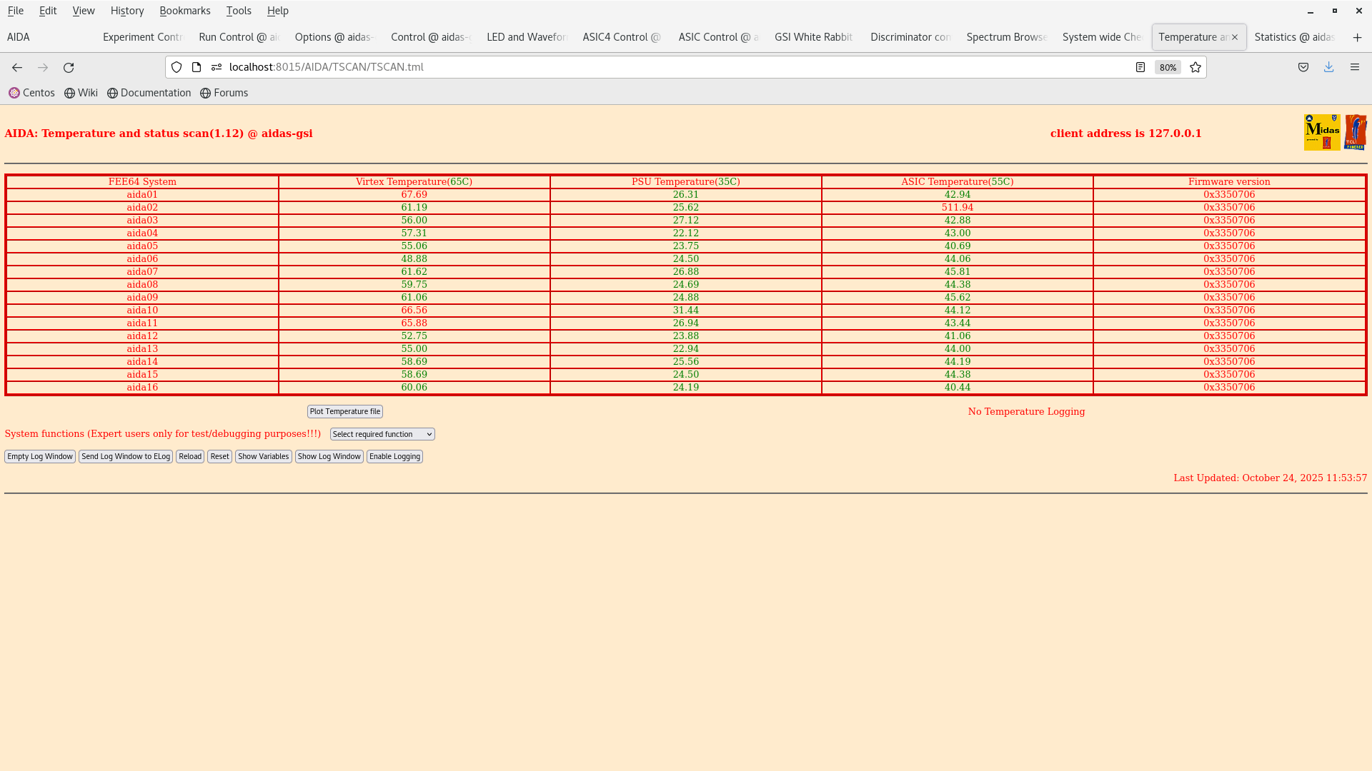
      FEE64 temperatures OK - attachment 2
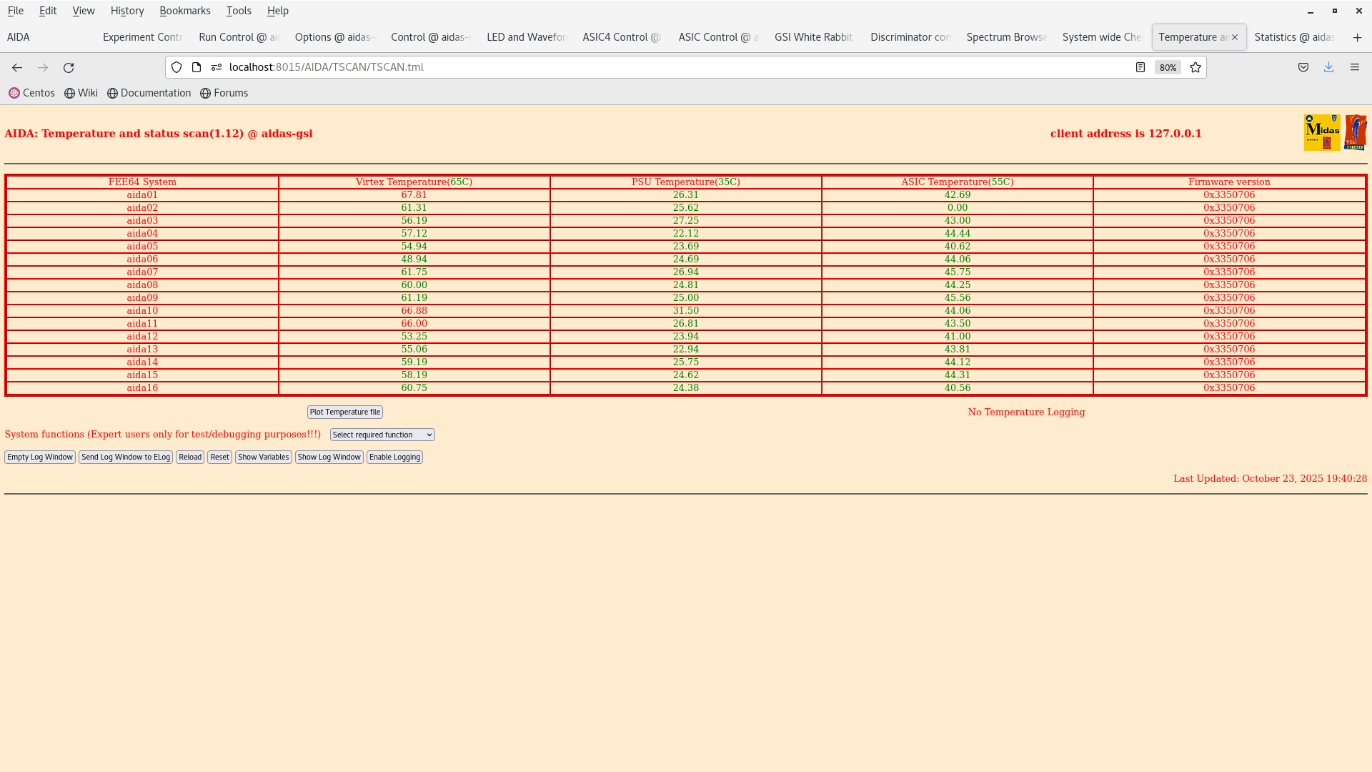
       aida02 ASIC temperature often reporting zero but sometimes a sensible value - presumably PT100 fault

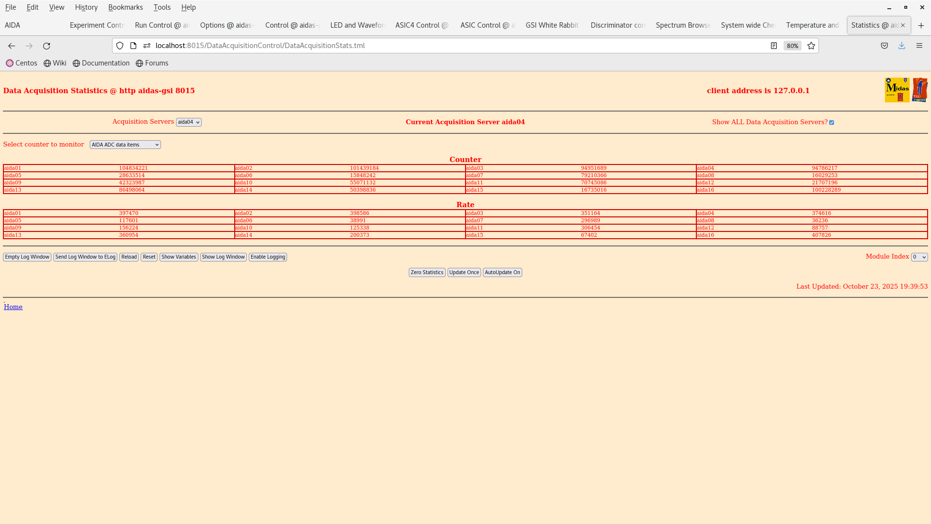
      ADC data item stats - attachment 3
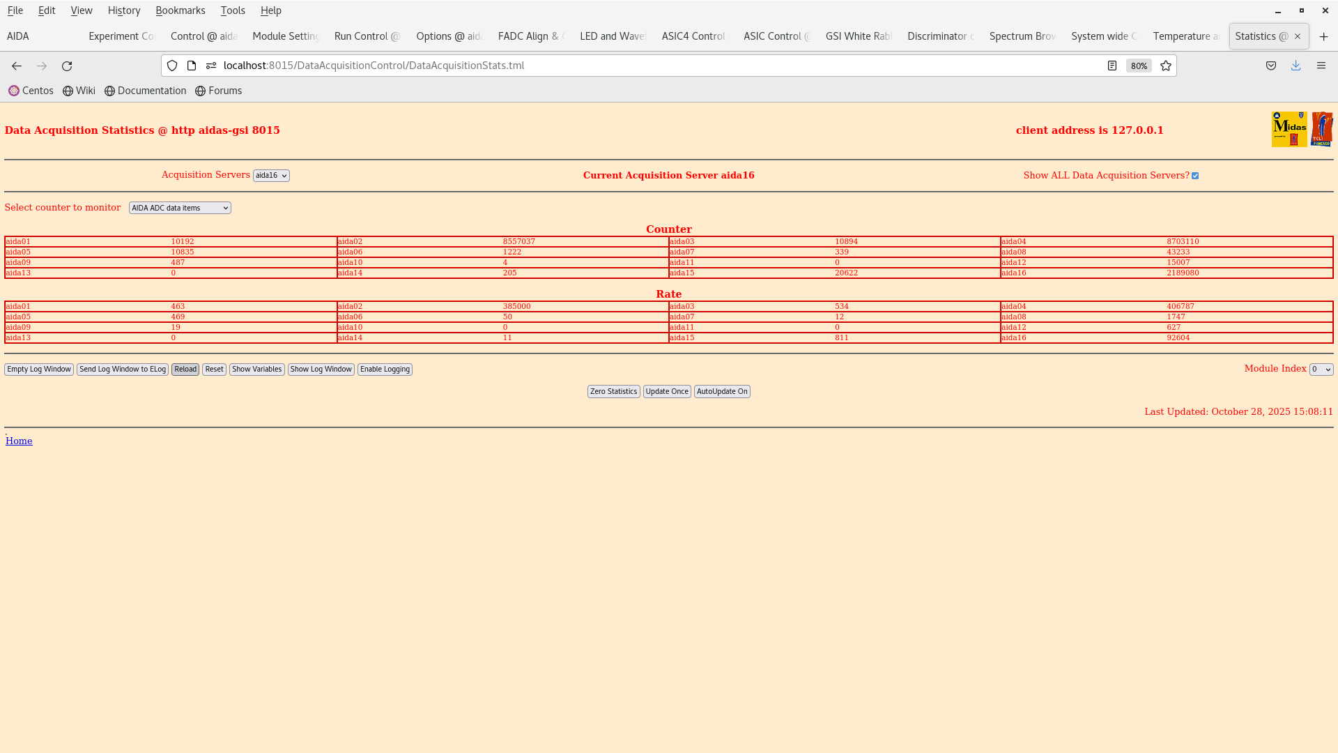
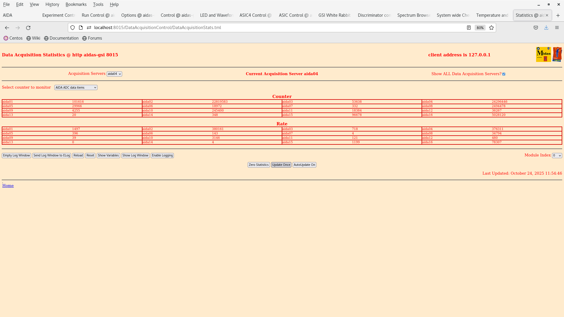
       all FEE64s at high/very high rates - only 3x of 16x FEE64s < 100k
       ASIC settings per aida01-aida04
        p+n FEE64s slow comparator 0xa, n+n FEE64s 0xf cf. 0x64 used for previous tests by Nabil?

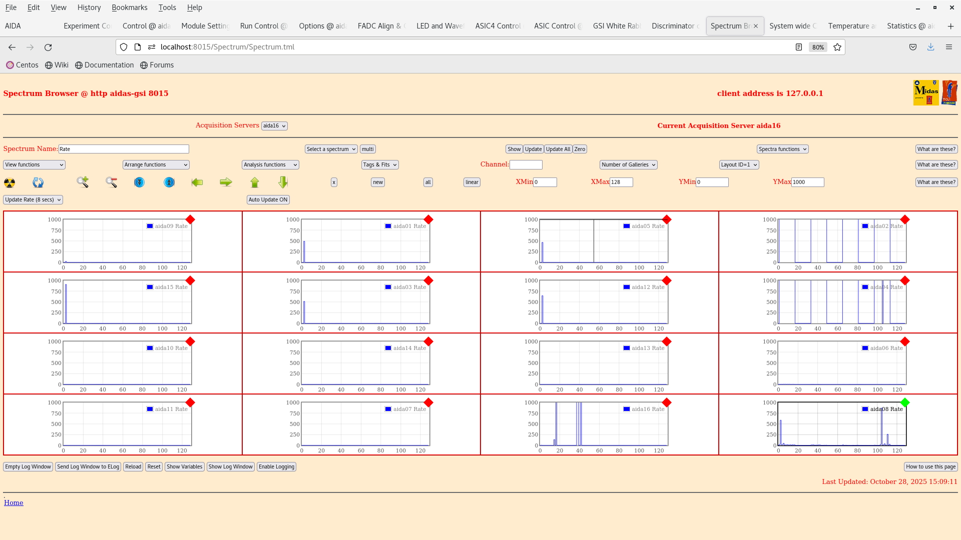
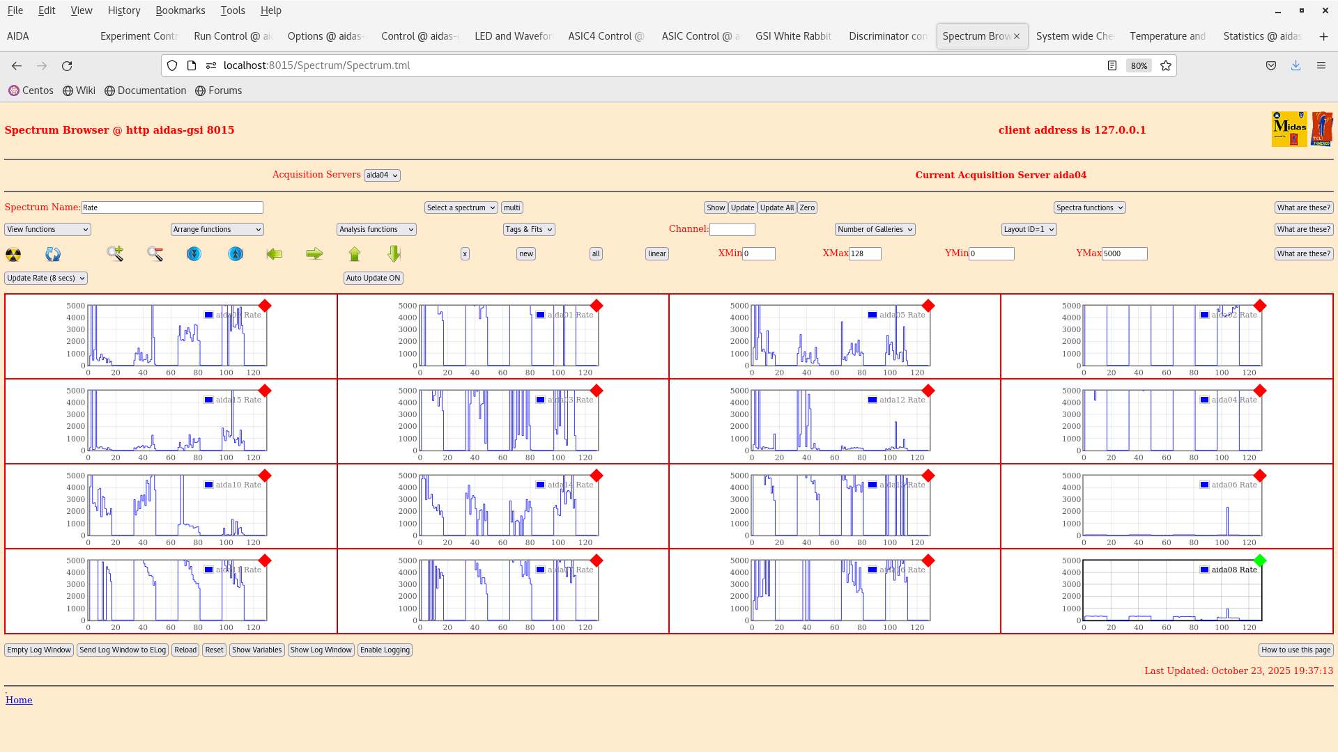
      per FEE64 Rate spectra - attachment 4

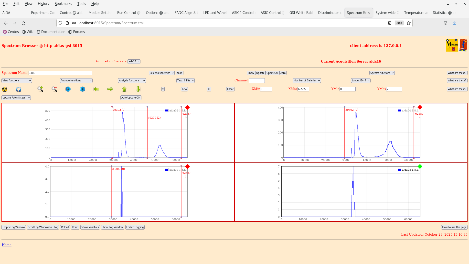
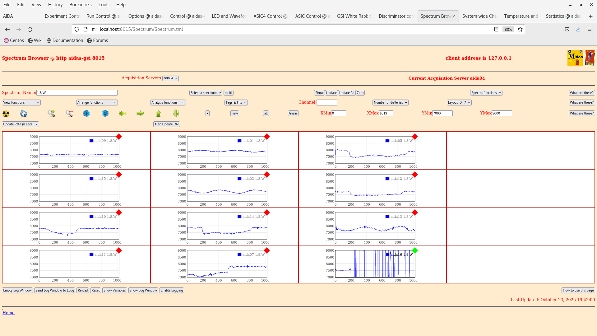
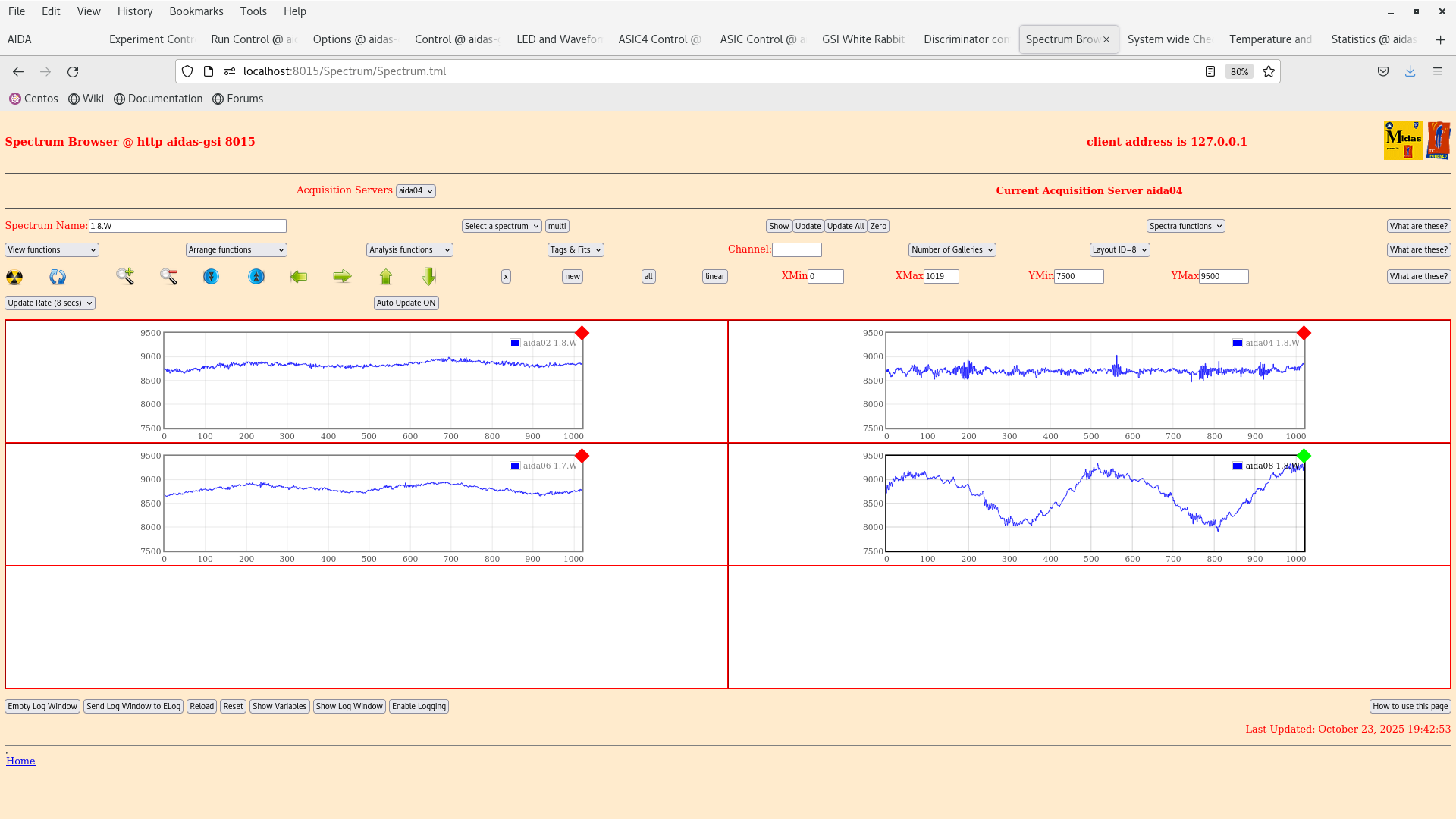
      per FEE64 1.8.W spectra - 20us FSR - attachments 5-6


19.55 Switch to safe state (FEE64 power OFF, DSSSD HV OFF) overnight as appears to be unattended/not monitored overnight.

      Tomorrow I would suggest resuming tests (using slow comparator 0x64) and checking per FEE64 pulser peak width for comparison with previous tests by Nabil. If
unable to reproduce previous tests (or previous AIDA performance) you will need to check setup/reduce noise to be able to perform measurements using the 207Bi source. |
| Attachment 1: Screenshot_from_2025-10-23_19-44-28.png
|
|
| Attachment 2: Screenshot_from_2025-10-23_19-40-38.png
|
|
| Attachment 3: Screenshot_from_2025-10-23_19-40-10.png
|
|
| Attachment 4: Screenshot_from_2025-10-23_19-39-43.png
|
|
| Attachment 5: Screenshot_from_2025-10-23_19-42-13.png
|
|
| Attachment 6: Screenshot_from_2025-10-23_19-43-04.png
|
|
|
721
|
Thu Oct 23 12:22:31 2025 |
JB, GB, MP, AM, NH | 207Bi source threshold tests |
>
> We have dismounted the AIDA stack and bPlast and realigned the cables so that they can fit into the adapters.
>
> The plan for the next couple days is the following:
>
> - Alignment -- done
> - Remount cable -- done
> - Fix position w/o bPlast mounted -- done
> - Remount bracket for the last stage -- done
> - Remount AIDA 1 & 2 and the 207Bi source with the source holder -- done
> - Mount the snout and take data -- we wait till next week Monday when the heat exchanger is active again. (ongoing)
>
> The current setup at the end of work is that the snout is mount with a bPlast (uncabled) and 2 AIDA layers at the regular spaced position with a 207Bi source down stream, as can be seen in the previous elog. The source is ~1 cm away from the middle AIDA wafer.
>
> Currently what is cabled:
>
> - Signal out from the detector
> - Bias daisy chain
>
> Still to be cabled:
>
> - HV cable
> - Grounding
> - Pulser
>
> Additional info on the source position:
> - the source is at ~9.6 mm distance from the downstream detector
> - the source is placed at the centre of the middle wafer: 12.25 cm in x, 4.75 cm in y
> - the radius of the source is ~1.5 mm

The Messhuette has been cleaned and equipment has been rearranged. If there are any broken or missing components be sure to follow up with the FRS group (as I believe they have been cleaning here).

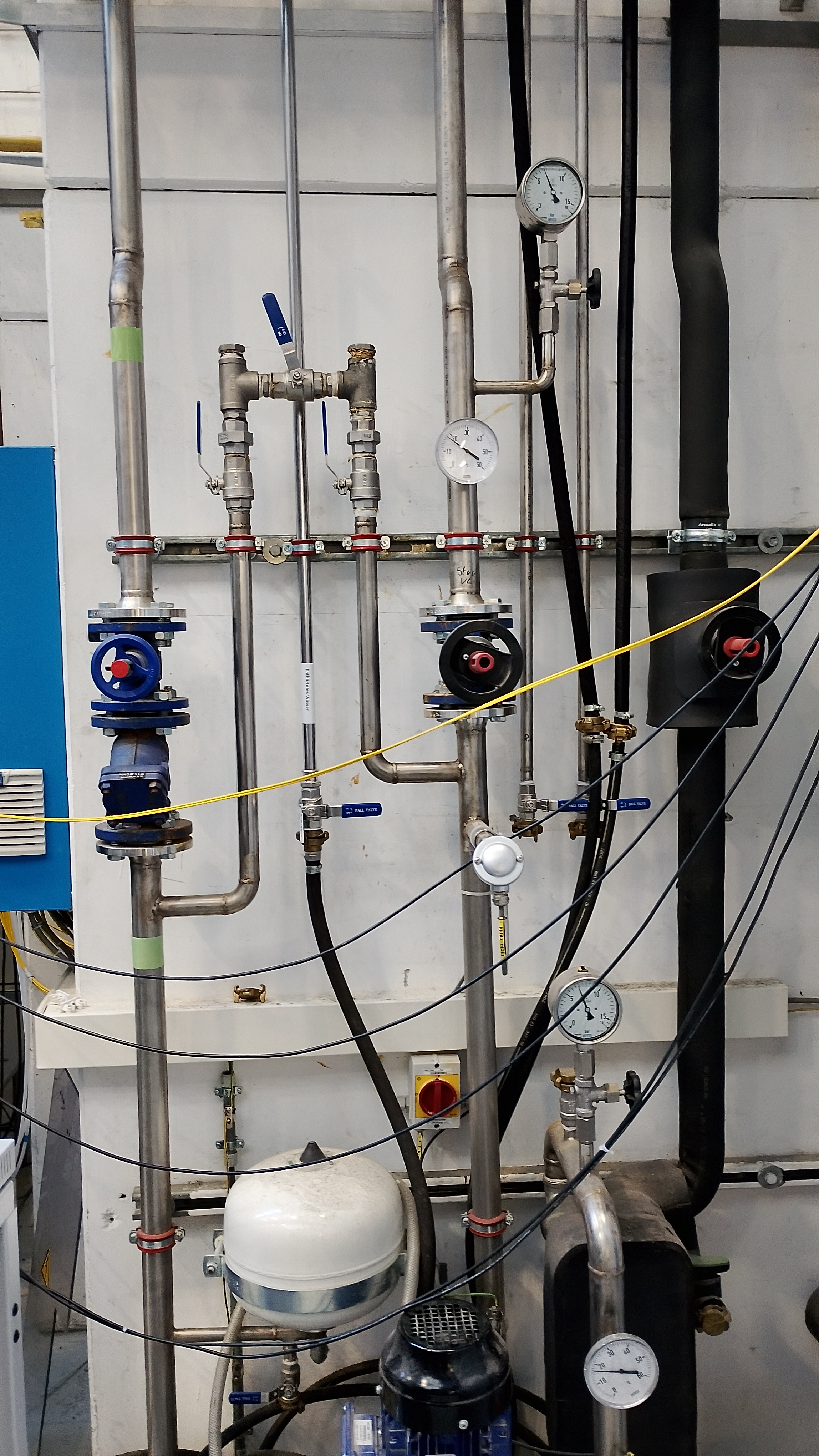
We are resuming the work on the source measurements as the cooling water is back. Some of the valves still look closed so we are investigating if the water is flowing to the setup.

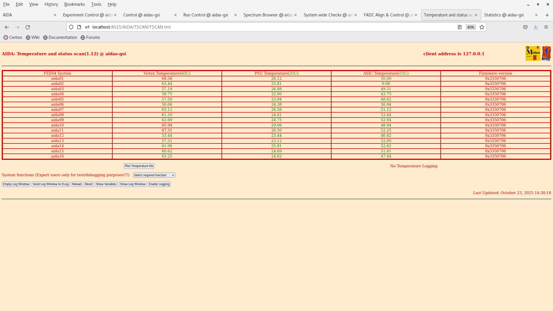
14:31 Temperature on start up OK - attachment 2.

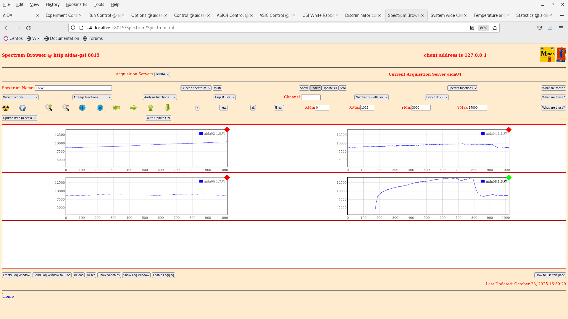
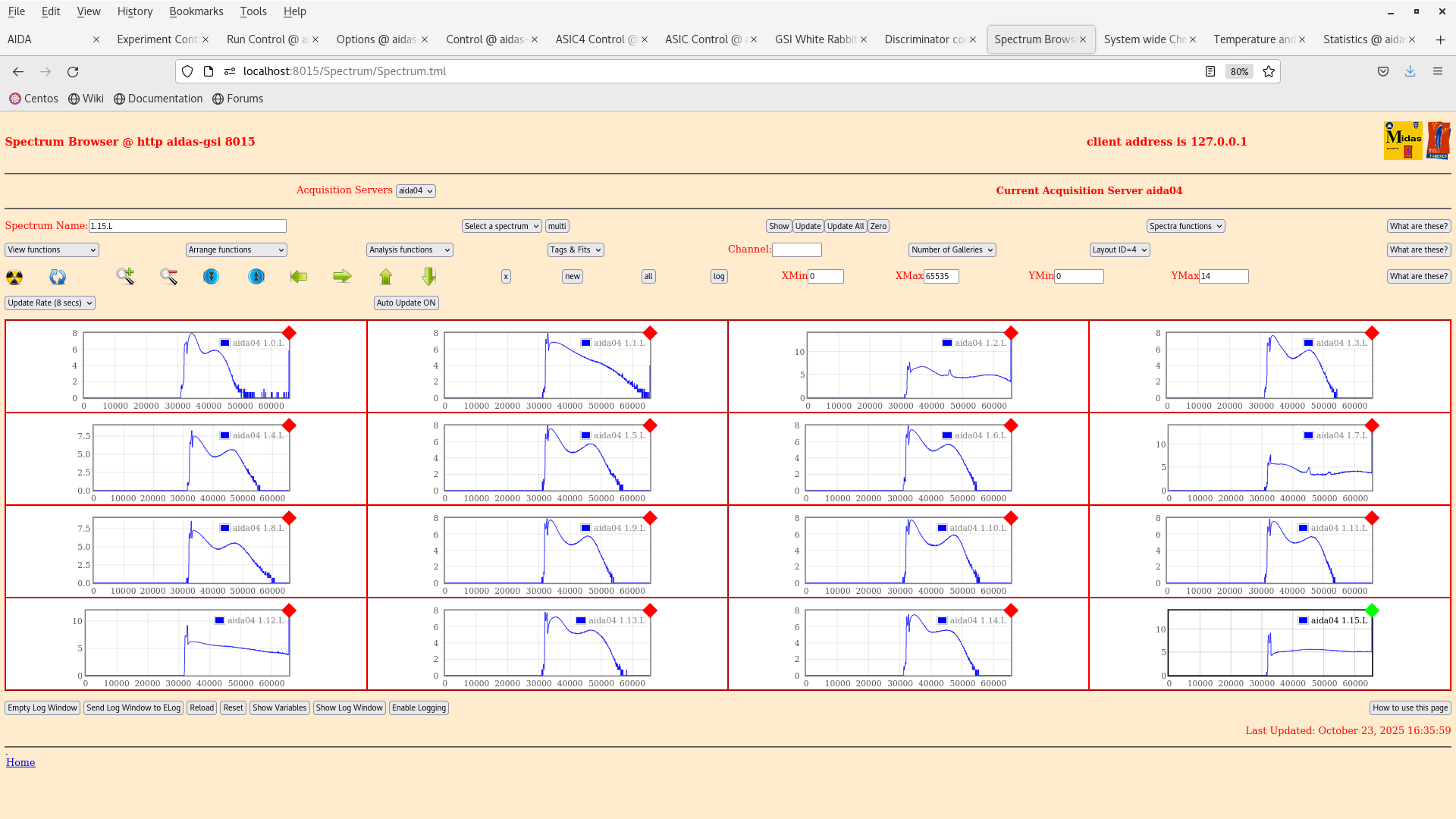
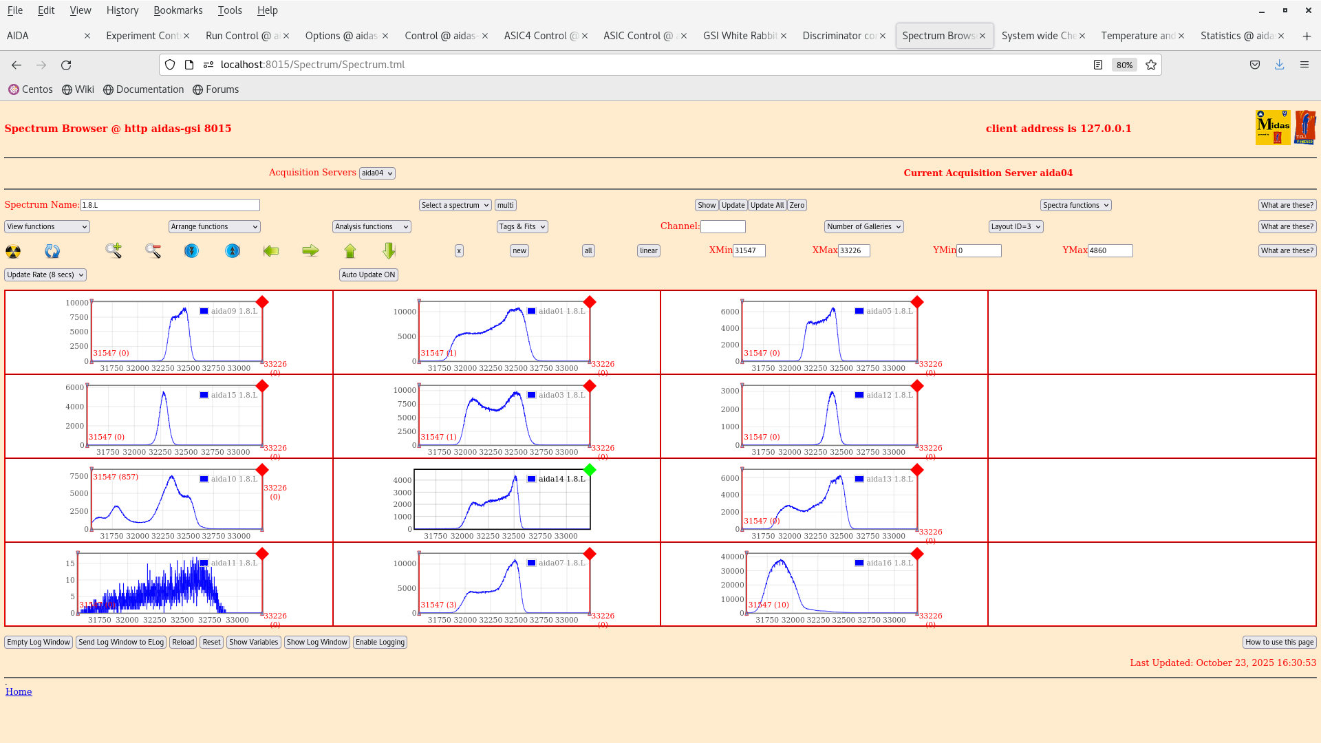
15:41 We reset the ASIC control registers to a setup used in Feb 2024 (2025Feb24-17.14.52) to match the full AIDA setup (it was using BB7 initially in aida10).

The old bias scheme is obsolete and the bias is now done via the Ohmic side.

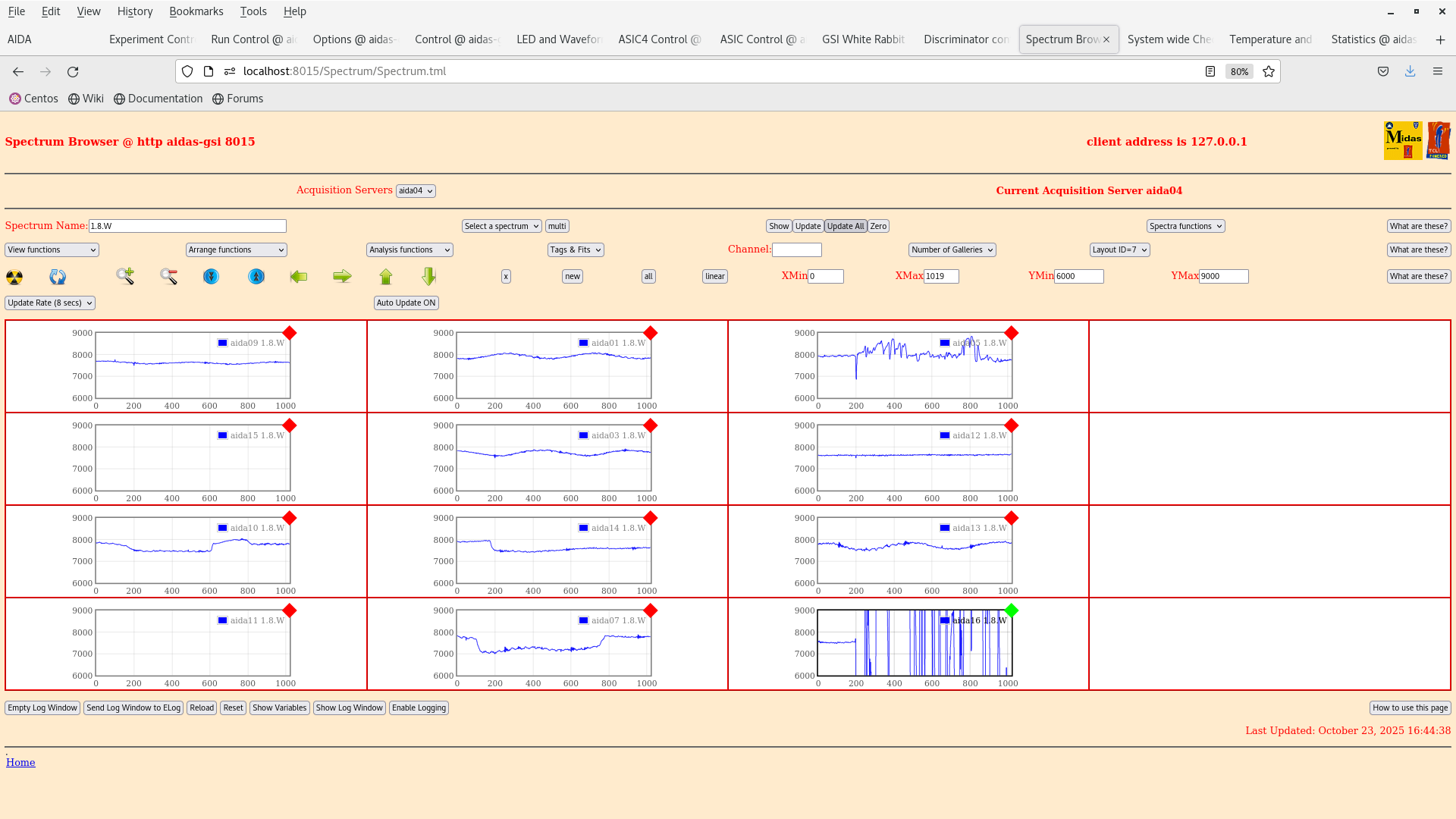
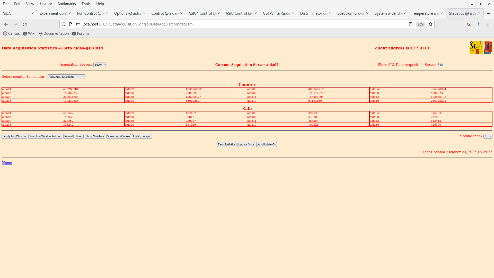
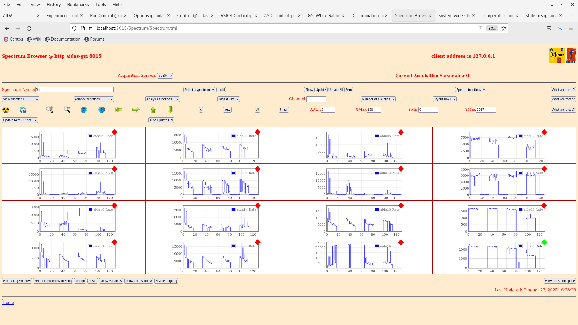
16:47 We have look at some initial spectra with the 207Bi 3-8 shows the ADC channels and waveforms of the n+n and p+n sides. Bias and grounding developed by Nabiel have been done.

We are going to wait for the system to stabilise over night so that we start taking data tomorrow. Then we can analyse the results and see what we get :) Some channels are clearly broken which can be seen in the waveforms eg. aida16. |
| Attachment 1: IMG_20251023_132958.jpg
|
|
| Attachment 2: Screenshot_from_2025-10-23_14-30-28.png
|
|
| Attachment 3: Screenshot_from_2025-10-23_16-44-41.png
|
|
| Attachment 4: Screenshot_from_2025-10-23_16-39-32.png
|
|
| Attachment 5: Screenshot_from_2025-10-23_16-36-03.png
|
|
| Attachment 6: Screenshot_from_2025-10-23_16-31-33.png
|
|
| Attachment 7: Screenshot_from_2025-10-23_16-29-28.png
|
|
| Attachment 8: Screenshot_from_2025-10-23_16-29-15.png
|
|
|
720
|
Wed Oct 15 09:41:24 2025 |
JB, GB, MP | 207Bi source threshold tests |
We have dismounted the AIDA stack and bPlast and realigned the cables so that they can fit into the adapters.

The plan for the next couple days is the following:

- Alignment -- done
- Remount cable -- done
- Fix position w/o bPlast mounted -- done
- Remount bracket for the last stage -- done
- Remount AIDA 1 & 2 and the 207Bi source with the source holder -- done
- Mount the snout and take data -- we wait till next week Monday when the heat exchanger is active again. (ongoing)

The current setup at the end of work is that the snout is mount with a bPlast (uncabled) and 2 AIDA layers at the regular spaced position with a 207Bi source down stream, as can be seen in the previous elog. The source is ~1 cm away from the middle AIDA wafer.

Currently what is cabled:

- Signal out from the detector
- Bias daisy chain

Still to be cabled:

- HV cable
- Grounding
- Pulser

Additional info on the source position:
- the source is at ~9.6 mm distance from the downstream detector
- the source is placed at the centre of the middle wafer: 12.25 cm in x, 4.75 cm in y
- the radius of the source is ~1.5 mm |
| Attachment 1: IMG_5796.jpg
|

|
| Attachment 2: IMG_5797.jpg
|

|
| Attachment 3: IMG_5798.jpg
|

|
|
719
|
Mon Oct 13 15:04:53 2025 |
JPB, NH, GB, MP | Dismount AIDA and realign the cables |
We have dismounted the AIDA stack and bPlast and realigned the cables so that they can fit into the adaptors.

The plan for the next couple days is the following:

- Alignment -- done
- Remount cable -- ongoing
- Fix position w/o bPlast mounted --
- Remount bracket for the last stage --
- Remount AIDA 1 & 2 and the 207Bi source with the source holder --
- Mount the snout and take data --

The tests we want to perform are the following:

- Energy distribution in x and y for ADC items and cluster
- The cluster size from conversion electrons
- ADC offsets with the 207Bi source after performing a pulser walkthrough
- Threshold test /w a 207Bi source - varying the threshold as while the source is in place and seeing when the 207Bi peaks are cut off.
- Background run without the 207Bi source (after the above tests)
- Possible test with a 152Eu source as well to measure conversion electrons from Eu could also be an option but we would need to discuss how to do this since all the 152Eu source are closed. We could possibly measure the compton edge from this
data. |
| Attachment 1: IMG_5778.jpeg
|

|
| Attachment 2: IMG_5779.jpeg
|

|