| |
ID |
Date |
Author |
Subject |
|
|
101
|
Tue May 5 16:40:23 2015 |
JA, TD, AE, CG & JLT | Wednesday 6 May 2015 |
00.00 Degrader changed to 4mm + some of variable (need to confirm)
      Extra 1mm removed.

00.30 R63
      95Br BigRIPS setting -> 94Se
      Degrader ?

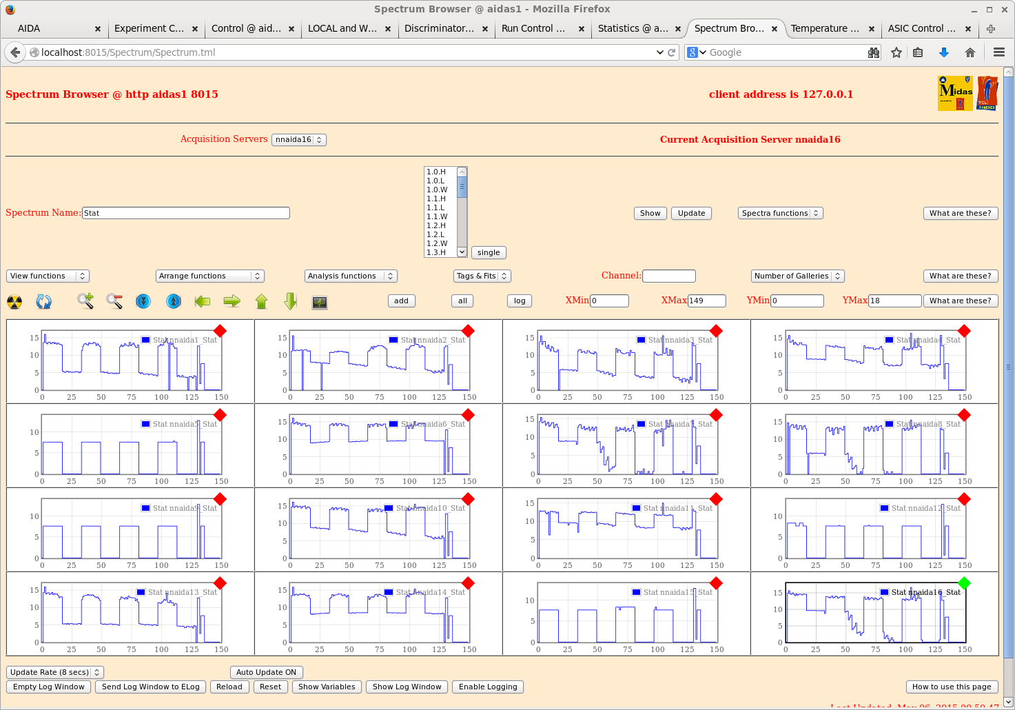
      FEE64 nnaida1-16 stat spectra (attachment 1)

00.50 Beam tuning for 100Kr started
      Degrader changed to 4mm  fixed + 0.6mm + 0.2mm variable
      => total 4.8mm

09.40 Found detector bias DSSSD #1 tripped
      Detector trips at +20uA at ~ +10V

10.45 R63 stopped

10.45 Bias(V) I_L(uA)    set 50uA trip current
      10      45.105
      20      trips at ~15V
      2       4.450
      4       ~7.4 rising to ~9.4 over ~2 mins
      6       20.4 and rising

      Not open circuit. Not Ohmic. Radiation damage?

      Time between successive 32000 block data files changes from  ~5-6 mins to ~3-4 mins
      07.57-08.00. SEASTAR Elog records F/C drops in at 08.20. Nishimura-san reports MAKI
      DAQ stopped/stalled c.08.00. Abrupt failure?

11.15 R64
      DSSSD #1 off
      nnaida6, 10, 11 & 16 slow comparator -> 0xff, medium/low energy selection -> 0x1

12.10 R64 stopped
      beam off

12.25 R65

14.09 R65 ends

      R66
      New ZDS setting (change in B-rho)
      F11 rate ~4kHz

~15.00 Degrader changed -> 4mm + 1.3mm (variable) Al

16.01 R66 ends

17.00 Checked CAEN N1419 ch #1 with/without bias cable and disconnecetd from DSSSD #1 - zero current
      at bias => problem forward of adaptor PCB

17.28 R68
      100Kr setting

      While tuning ZDS, observe few, if any, implants in DSSSD #2 & #3

18.30 Degrader changed to 4mm fixed + 0.4mm variable

19.16 R68 ends

      R69
Degrader -> 4mm + 0.4mm (variable) Al |
| Attachment 1: 140.png
|
|
|
|
102
|
Thu May 7 01:32:39 2015 |
JA, TD, AE, CG & JLT | Thursday 7 May 2015 |
09.25 R69 continues
      100Kr setting, degrader 4mm + 0.4mm (variable) Al
DSSSD #1 off due to detector failure ( https://elog.ph.ed.ac.uk/AIDA/101 ) |
|
|
103
|
Fri May 8 01:05:18 2015 |
JA, TD, AE & CG | Friday 8 May 2015 |
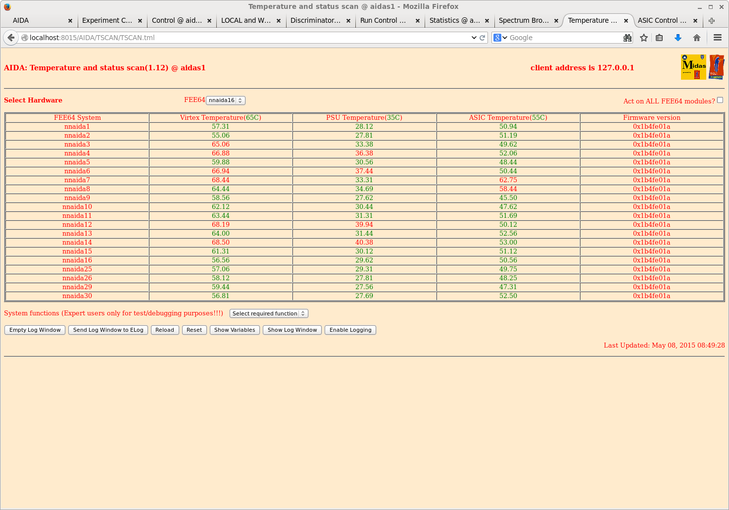
08.50 FEE64 temperatures (attachment 1)

09.03 R70 ends OK
      Beamtime ends

      R71
      background/residual activity

12.12 R71 ends

      R72
      Pulser walkthough, amplitude 90,000-10,000 @ 10,000 step, freq 25Hz

12.33 R72 ends
      External clock was removed by mistake - DAQ stopped
      Pulser data for amplitudes 90,000-50,000 only

      Ignore R73, R74

12.59 R75
Conclusion of pulser walkthrough for amplitudes 40,000-10,000 |
| Attachment 1: 150.png
|
|
|
|
73
|
Mon Apr 27 01:48:59 2015 |
JA, LHB, TD, VP, AE & CG | Monday 27 April 2015 |
DSSSD #1 +100V, +3.8uA
DSSSD #2 +100V, +5.5uA

09.48 nnaida16 stalled at DAQ GO
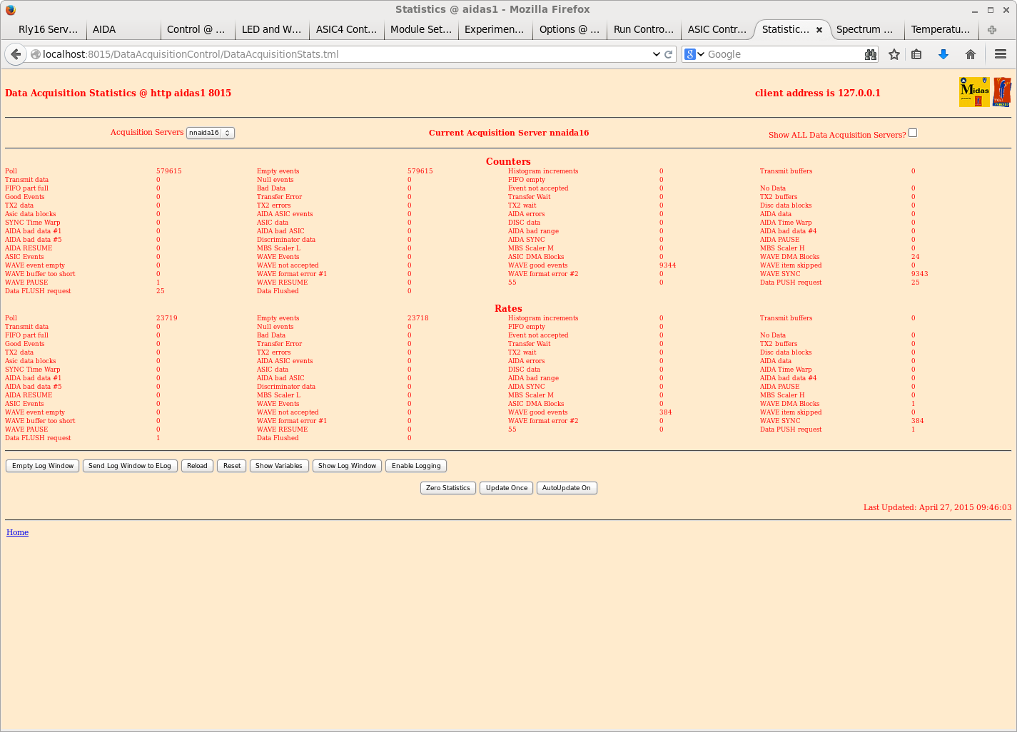
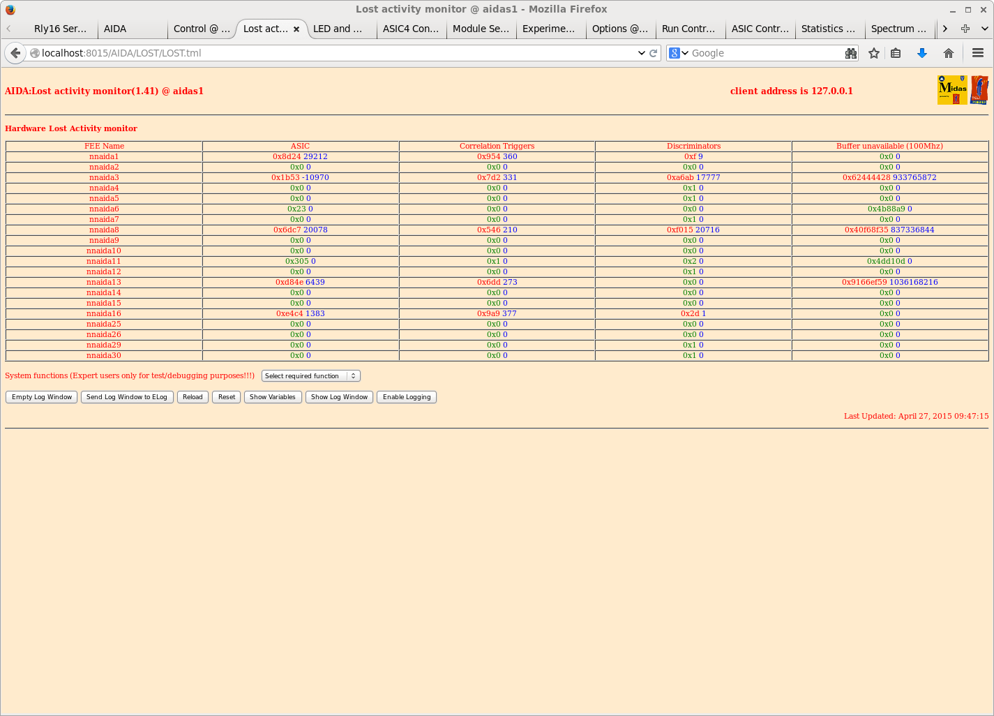
      see attachments 1 & 2 for statistics & lost activity monitors

1830: Current FEE configuration (looking downstream):

                                   |          |           |           |
                                   |     x    |nnaida25+26|     x     |
                                   |          |           |           |
                                   |     x    |nnaida17+18|     x     |
                                   |          |           |           |
                                   |     x    |nnaida9+10 |     x     |
                                   |          |           |           |
                                   |     x    | nnaida1+2 |     x     |


 |nnaida |nnaida |nniada |nnaida |                                      |nnaida |nnaida |nniada |nnaida |
 |27+28  |19+20  |11+12  |3+4    |                                      |7+8    |15+16  |23+24  |31+32  |

                                   |          |           |           |
                                   |     x    | nnaida5+6 |nnaida13+14|
                                   |          |           |           |
                                   |     x    |     x     |     x     |
                                   |          |           |           |
                                   |     x    |nnaida21+22|     x     |
                                   |          |           |           |
                                   |     x    |nnaida29+30|     x     |


       Detector 1 (3131-11) is connected to nnaida 10, 11, 6, 16
       Detector 2 (3058-09) is connected to nnaida 2, 4, 14, 7
       Detector 3 (2977-20) is connected to nnaida 1, 3, 13, 8

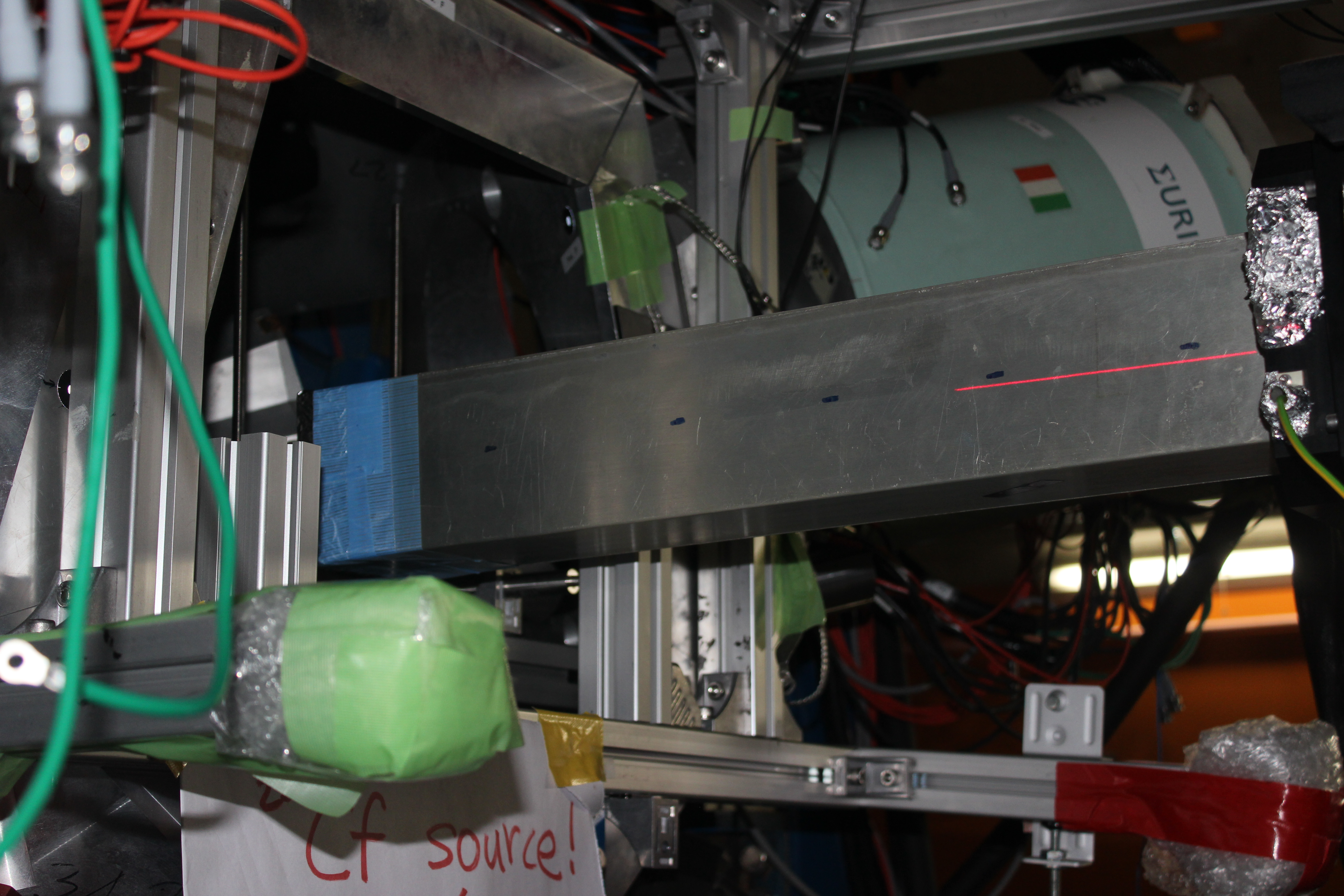
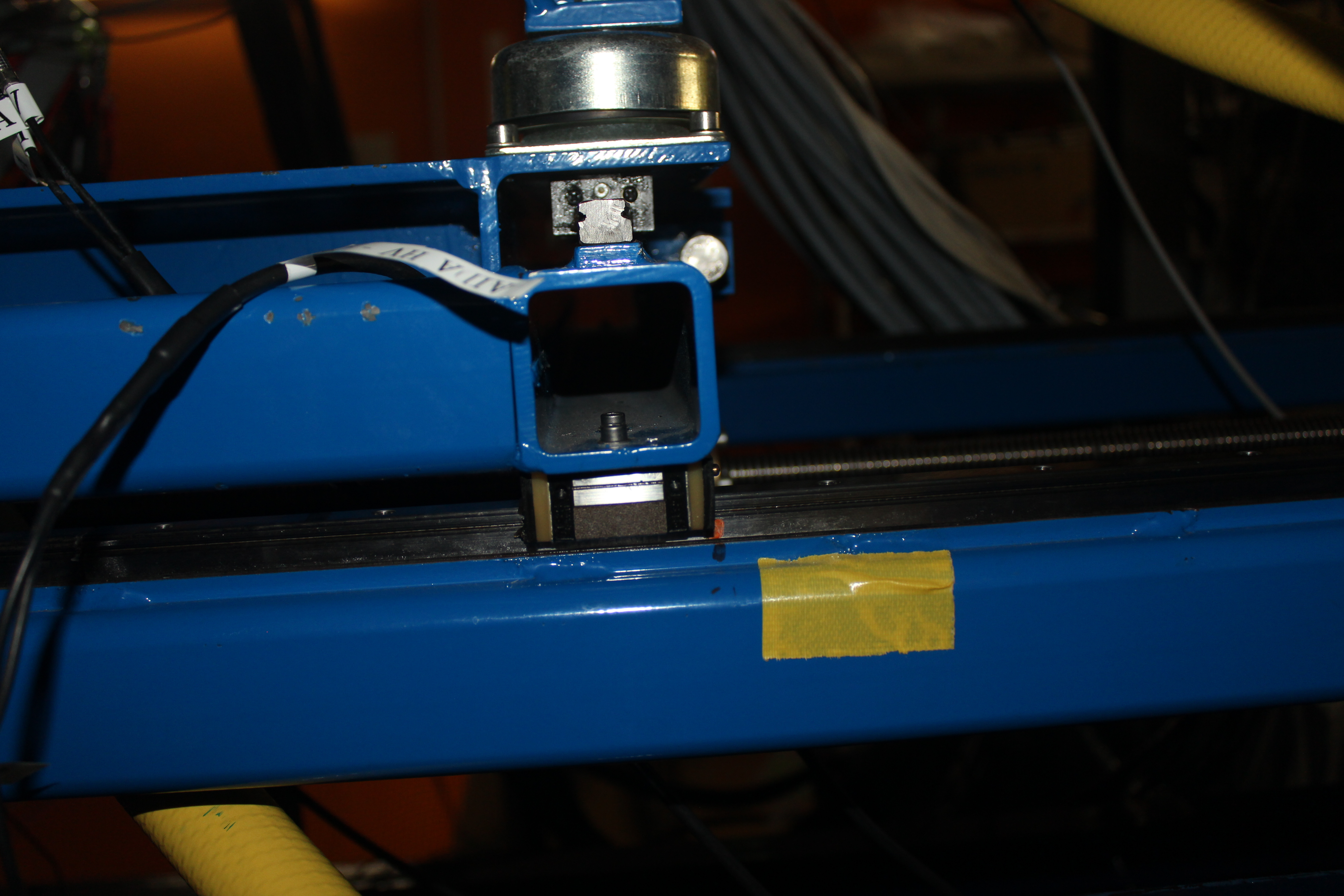
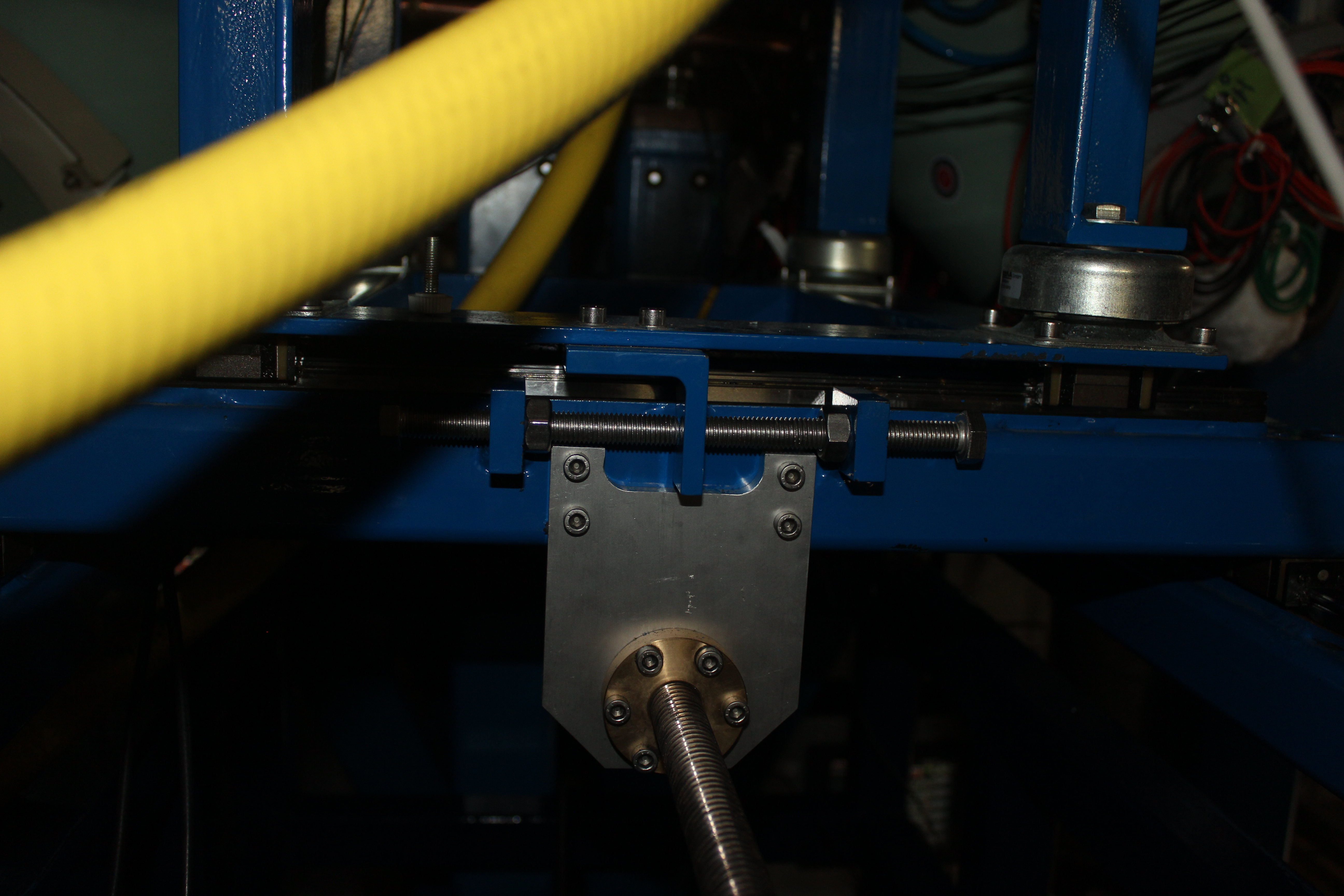
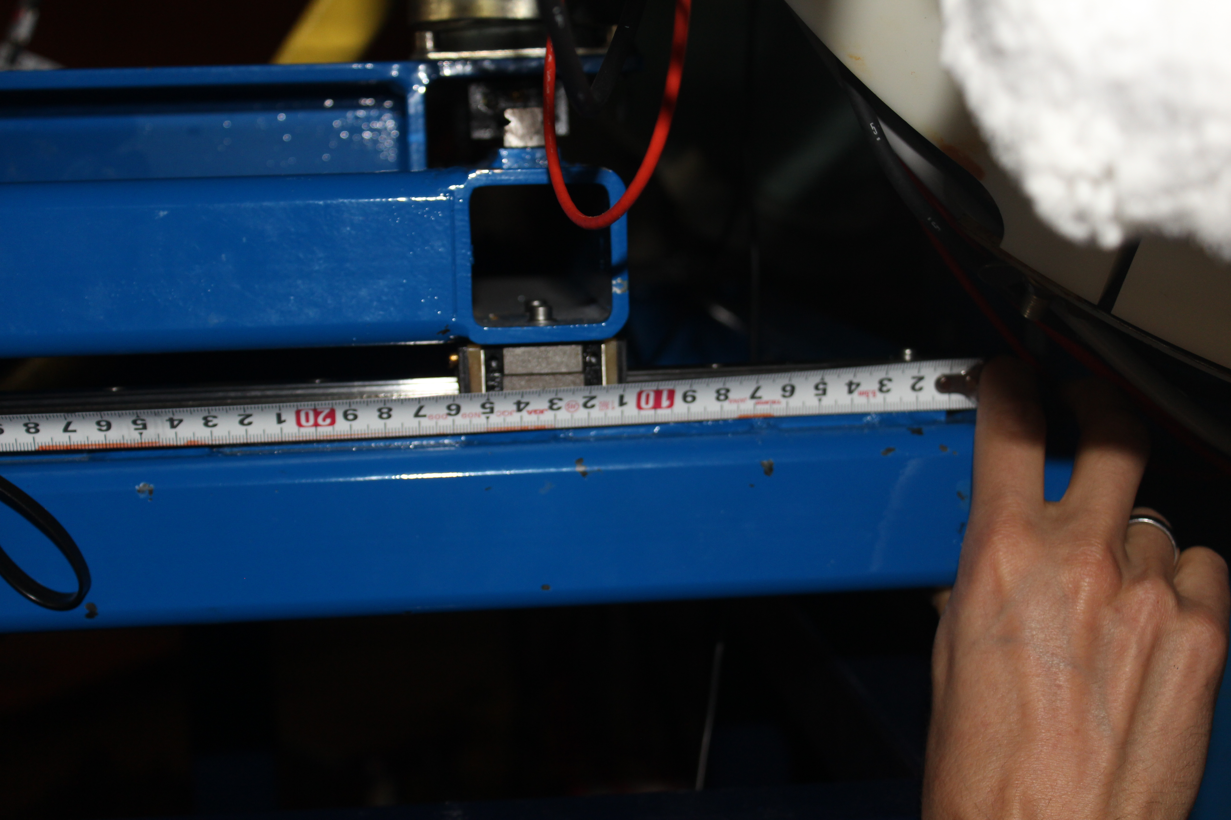
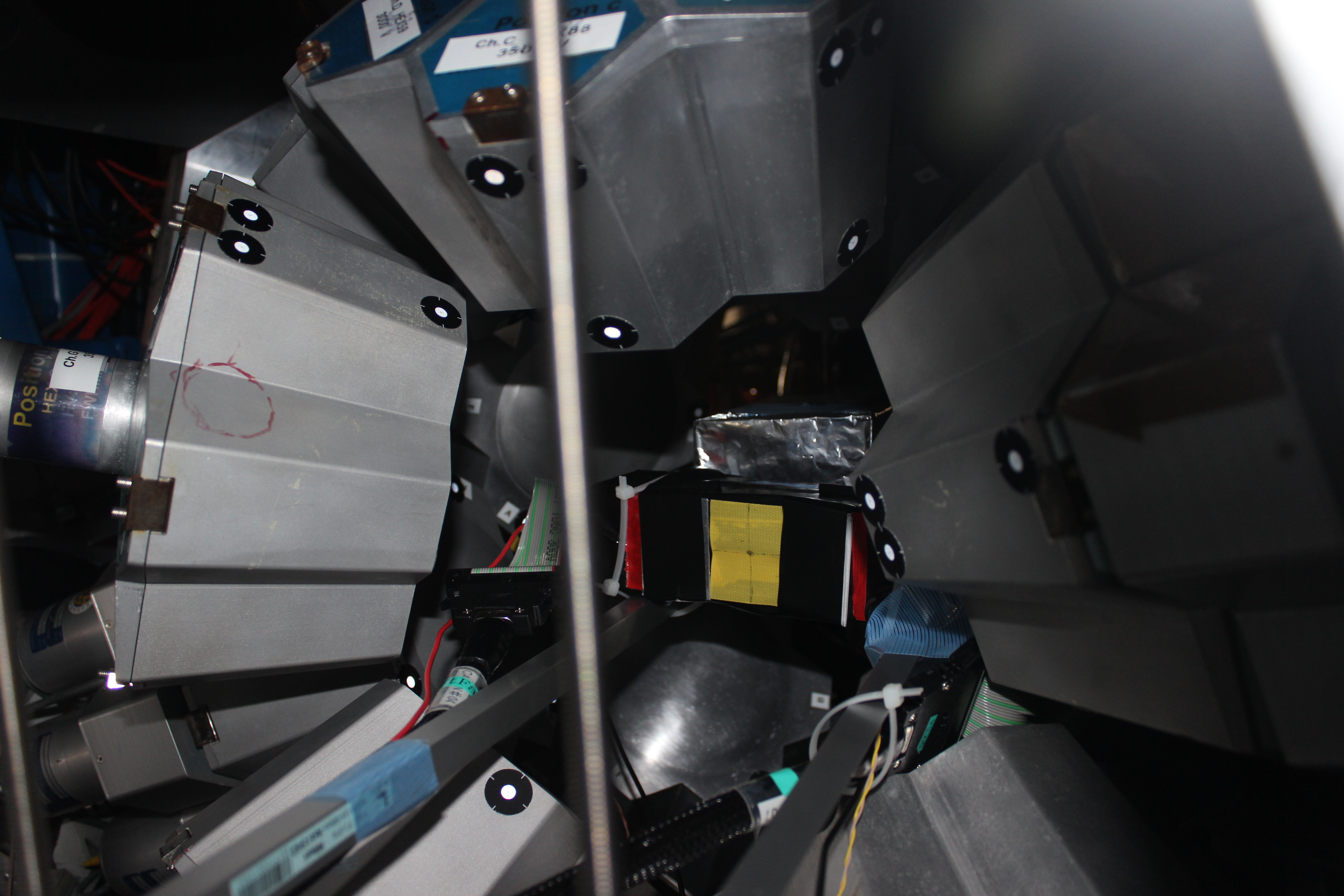
19.30 Check of AIDA alignment and positioning within EURICA
      See attachments 4-8

16.03 April 28  VP
     adding data sources (ie FEE64s) into the system and rules for TCP ports
  1) FEE needs to have an entry in the DHCP configuration  (/etc/dhcp/dhcp.conf)
    This assigns a host name (nnaidaxx) to the FEE based on ethernet MAC address and assigns an IP address
    10.1.1.xx   or  10.1.2.xx
     Also copy an existing file system in /MIDAS/XilinxLinux/ppc_4xx/rfs for nnaidaxx. This MUST be done as root
to preserve important file properties. (Use the existing tar file)
  2) The file /MIDAS/linux-ppc_4xx/startup/nnaidaxx  assigns xx as the AIDA Module Number and destination IP
port for created data.  In this example xx = 22.

    netstring TS_Server "myserver"
    netint TS_Port 11022
    netstring TS2_Server "myserver"
    netint TS2_Port 11122

    netint Aida_ModuleNum 22

    TS2_Server is currently not used

    So nnaidaxx  will send data to port 110xx in the Merger
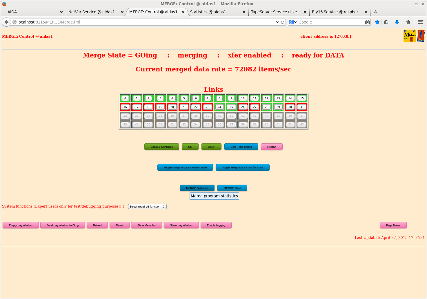
  3)  Add nnaidaxx to the list of ACQSERVERS in /MIDAS/config/TclHttpd/aidas1/startup.tcl
  4)  The Merger configuration file is  /MIDAS/Merger/AIDA/GS_configuration
      If the highest Aida ModuleNum is xx then modify the links definition so you have
              links xx  ./link64 11001
      Note that xx may be greater than the actual number of FEE modules if there are gaps in your name scheme
      The highest enabled IP port will be (11001 + xx - 1)
      You can enable/disable links to the Merge via the Merge GUI.
      Note: nnaidaxx appears to the Merge link table as link (xx-1).  So if you ask for 32 links they are
  0 => 31 in the Merge GUI table.
|
| Attachment 1: 20.png
|
|
| Attachment 2: 21.png
|
|
| Attachment 3: 22.png
|
|
| Attachment 4: IMG_2882.JPG
|
|
| Attachment 5: IMG_2889.JPG
|
|
| Attachment 6: IMG_2890.JPG
|
|
| Attachment 7: IMG_2891.JPG
|
|
| Attachment 8: IMG_2888.JPG
|
|
|
|
78
|
Wed Apr 29 01:03:41 2015 |
JA, LHB, TD, AE, CG & VP | Wednesday 29 April 2015 |
Overnight
      Beam tuning, PID tests - beam stopped in scintilator detector + 1" thick Pb bricks
      DAQ ran OK (not to disk)
      DSSSD #3 tripped, re-enabled OK


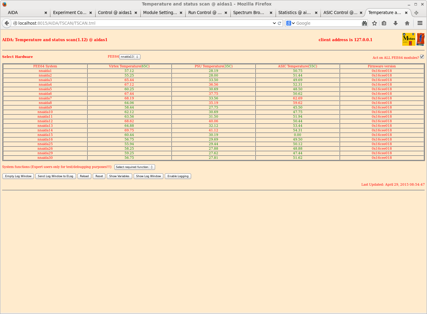
09.00 AIDA temperatures - attachment 1
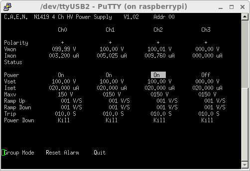
      CAEN N1419 HV settings - attachment 2

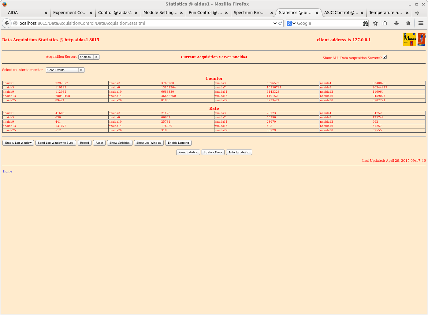
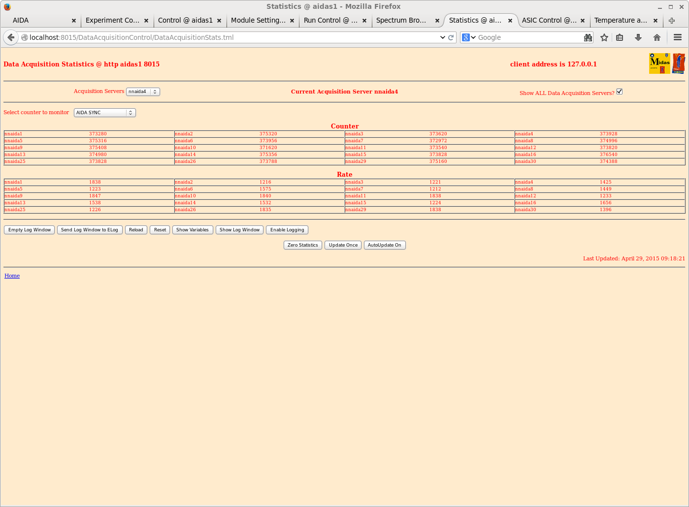
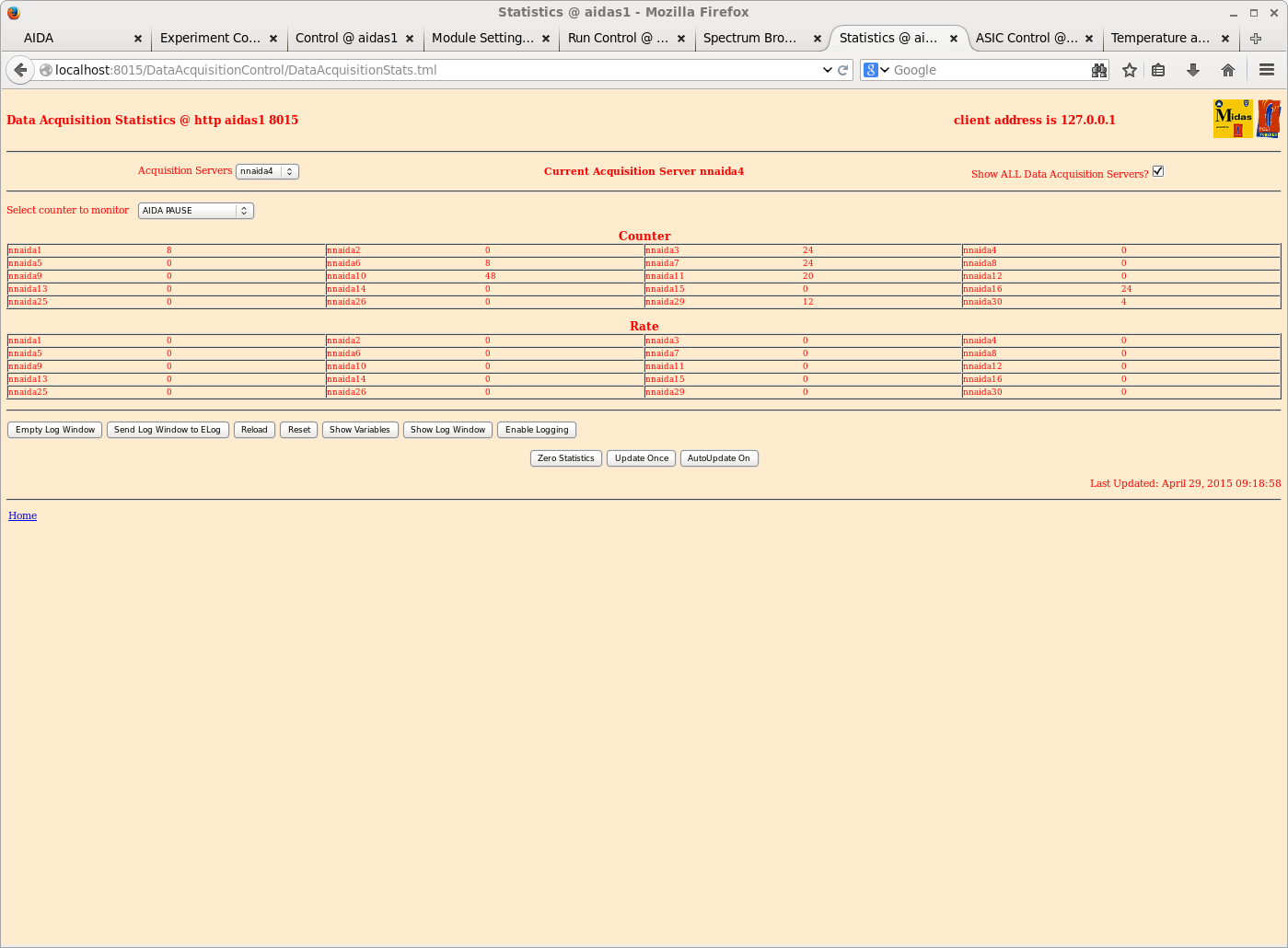
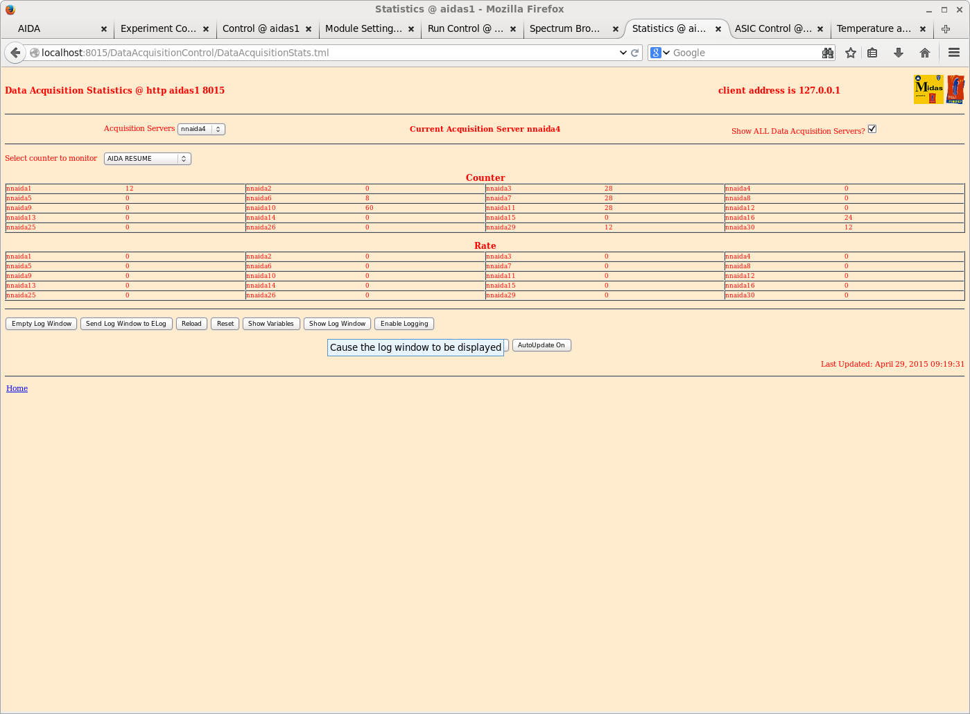
09.25 Statistics & lost activity - attachments 3-8

10.30 Scintilator detector + 1" thick Pb bricks removed
      ~1KHz 84Zn to Degrader + MICA + Veto + AIDA DSSSDs #1-3 + 10mm Al

      Data file R15 12.15-12.59 beam lost
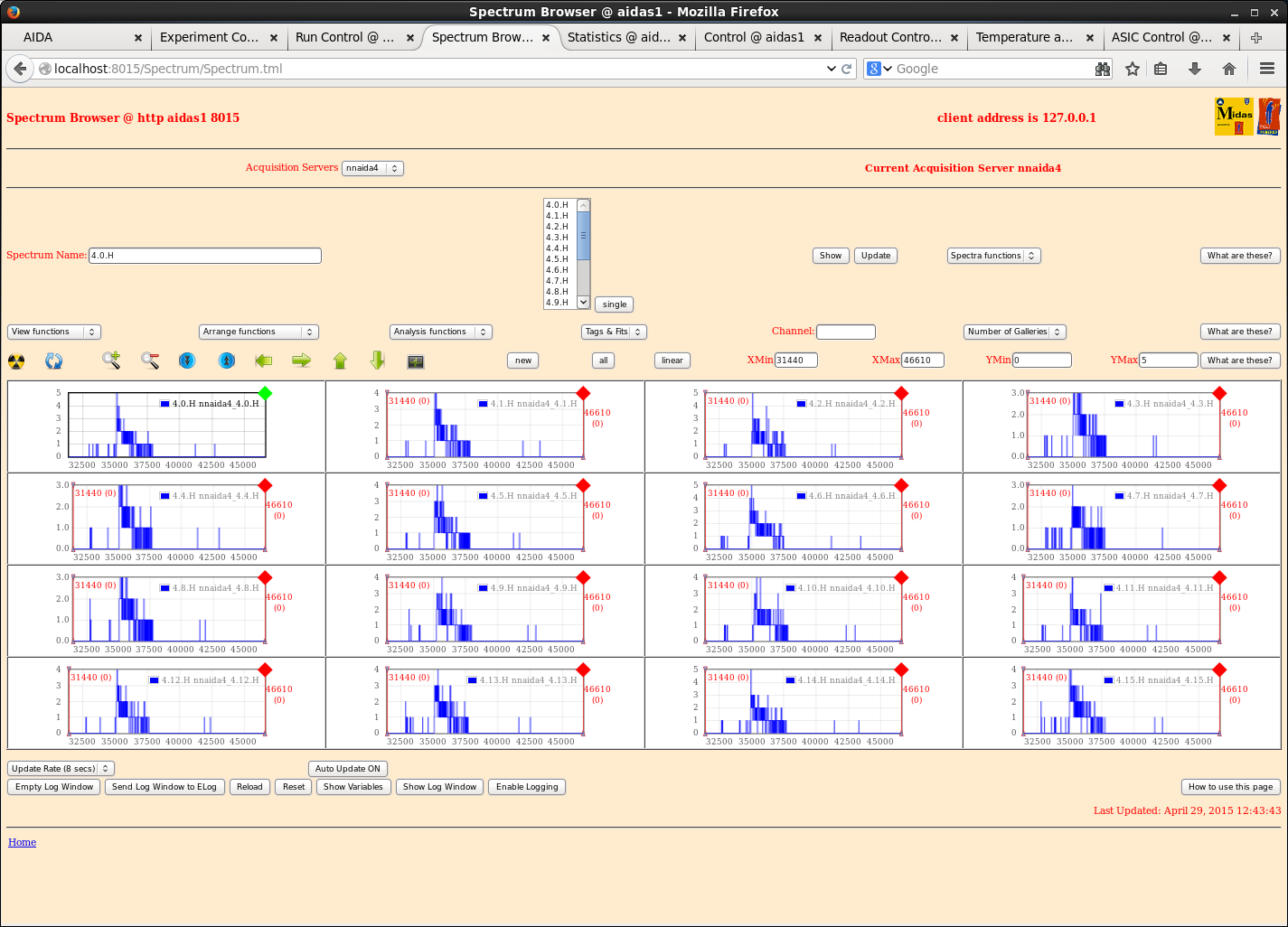
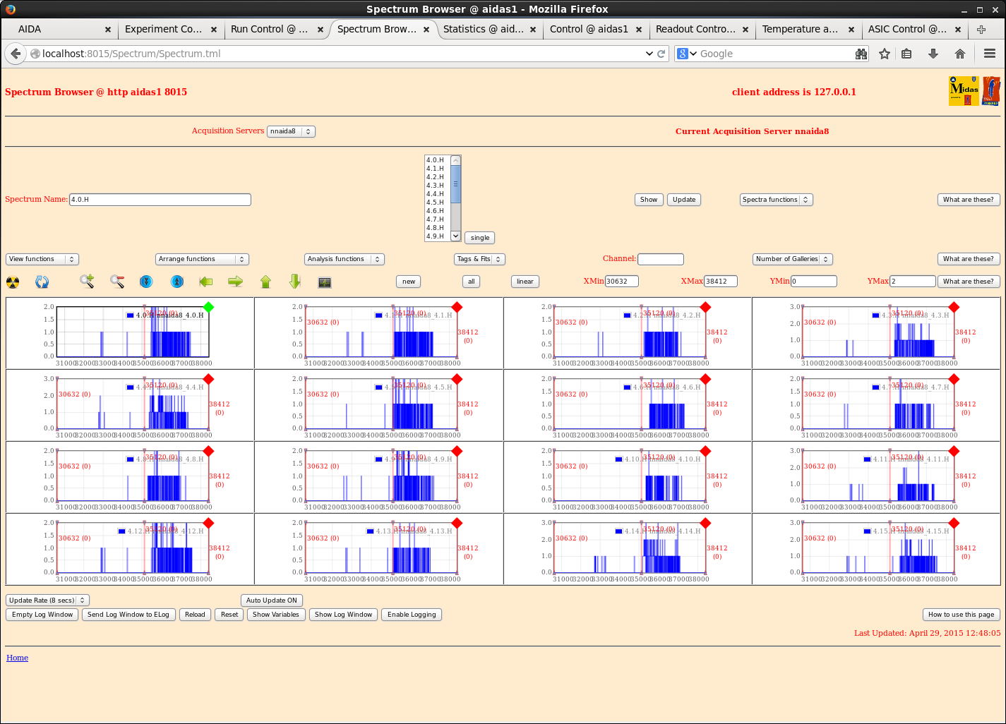
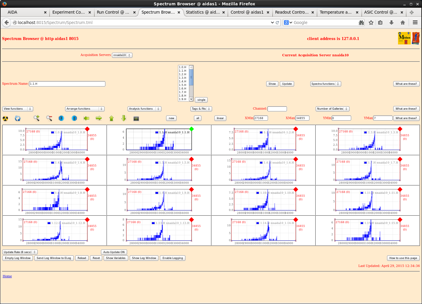
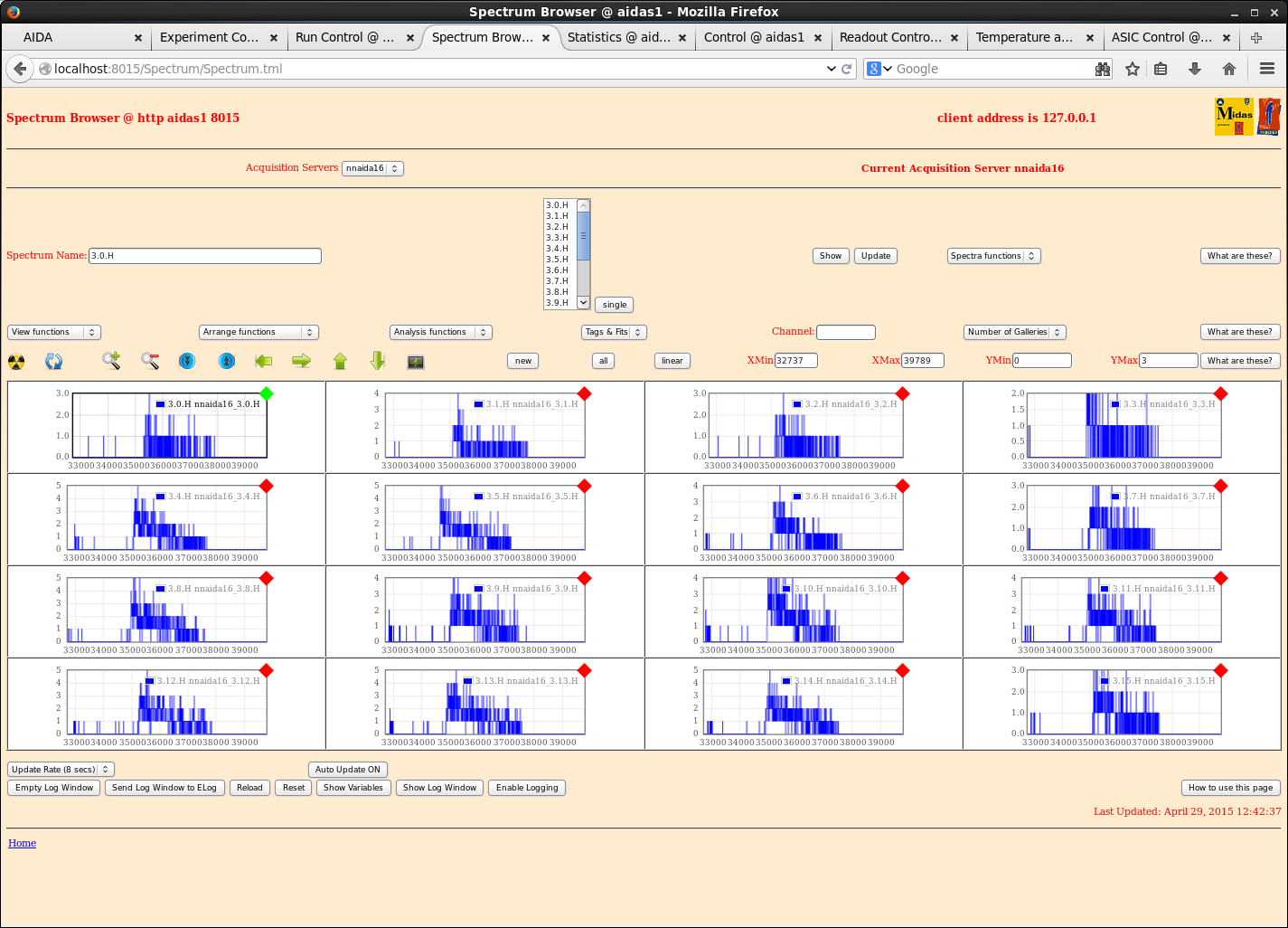
      Attachments 9-14 DSSSD #1-3 HEC ADC spectra, HEC LLD 0x08

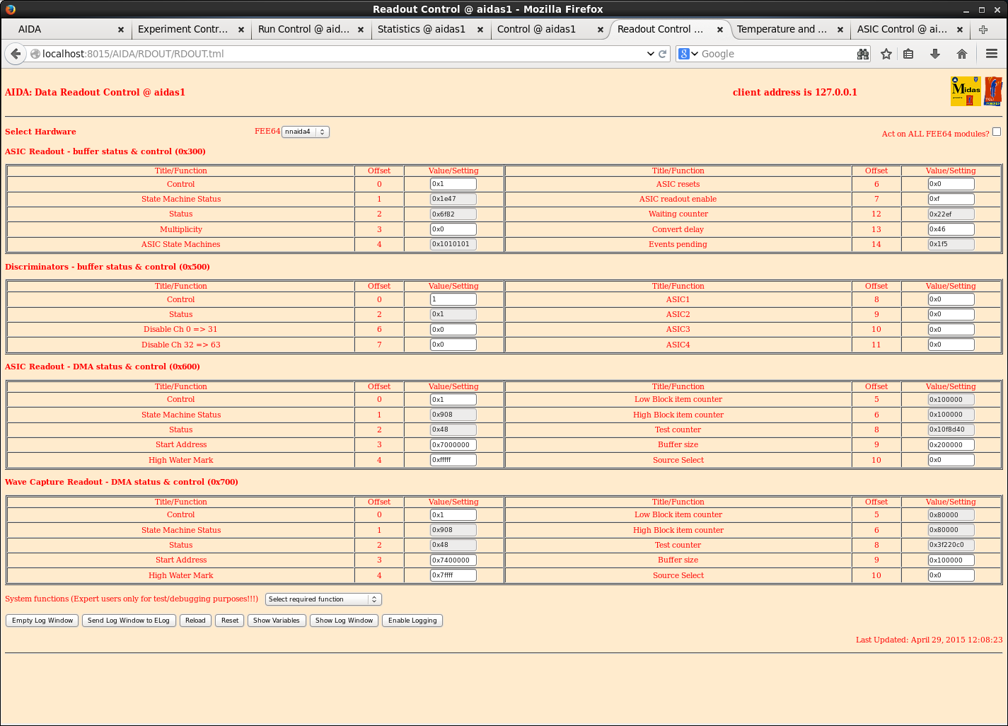
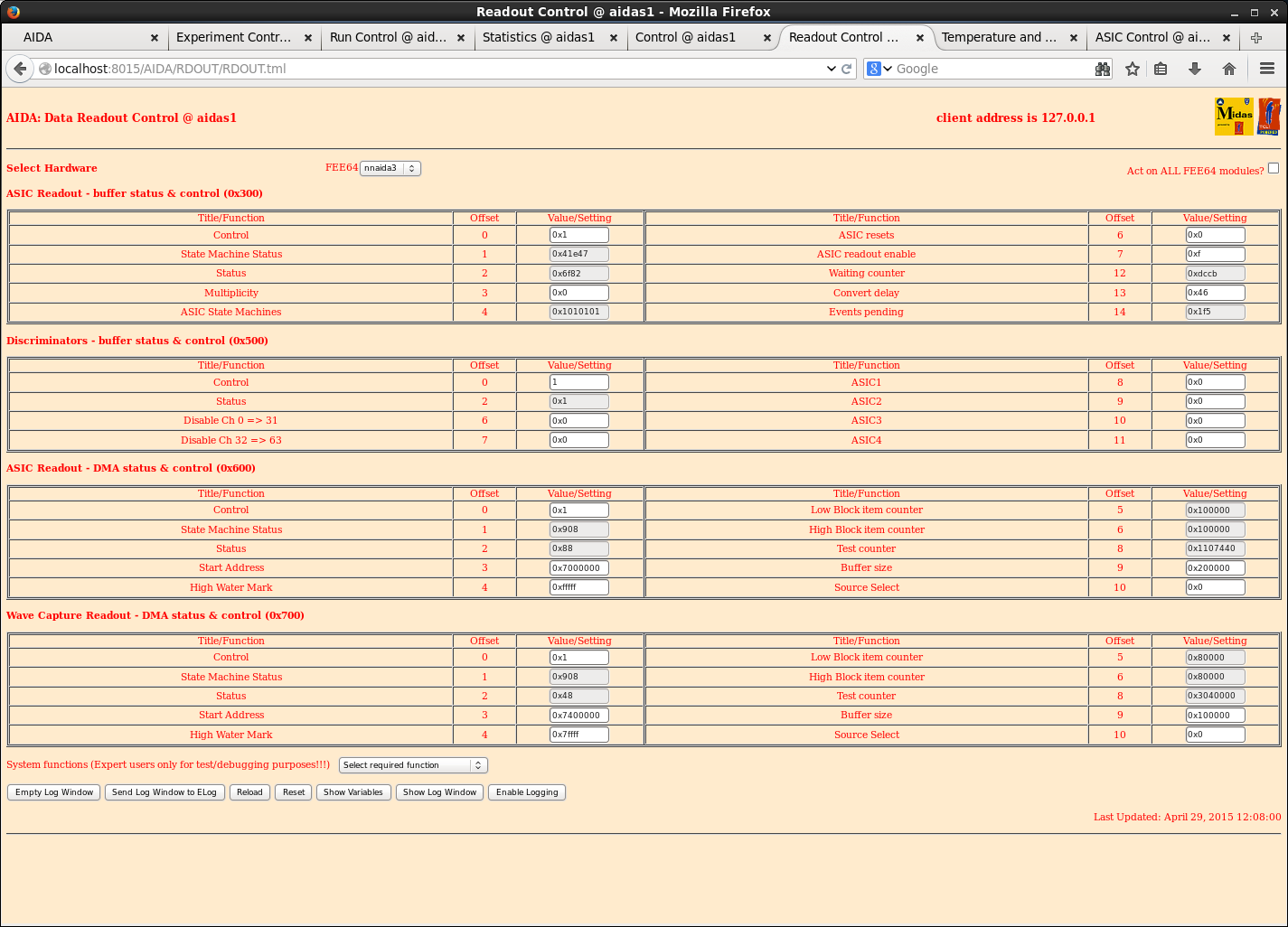
      Attachments 15-16 Examples of Data Readout Control following stalled DAQ GO (no SYNCs)

      Data file R16 13.02-13.46 SYNCs lost/MERGE stalled
      HEC LLD 0x02

      Data file R17 13.46-14.20

      Data file R19 15.30-17.05

      Data file R20 17.06
      Fast comparator LLD HEC 0x02, LEC 0x20 (except nnaida30 HEC 0x20)

22.14 Data file R22 22.14 - 30.4.15 09.00
      Now using /data20/TapeData/May2015 to store data
      Spectra cleared at start of run
      DAQ OK, CAEN N1419 ch #2 tripped
|
| Attachment 1: 31.png
|
|
| Attachment 2: 32.png
|
|
| Attachment 3: 33.png
|
|
| Attachment 4: 34.png
|
|
| Attachment 5: 35.png
|
|
| Attachment 6: 36.png
|
|
| Attachment 7: 37.png
|
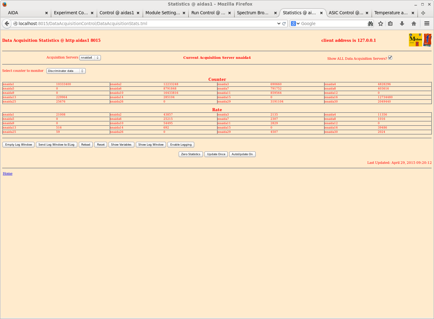
|
| Attachment 8: 38.png
|
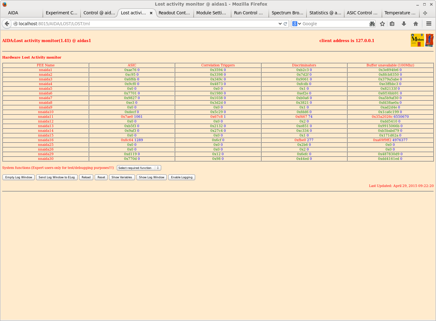
|
| Attachment 9: 20150429_nnaida1_det3_H.png
|
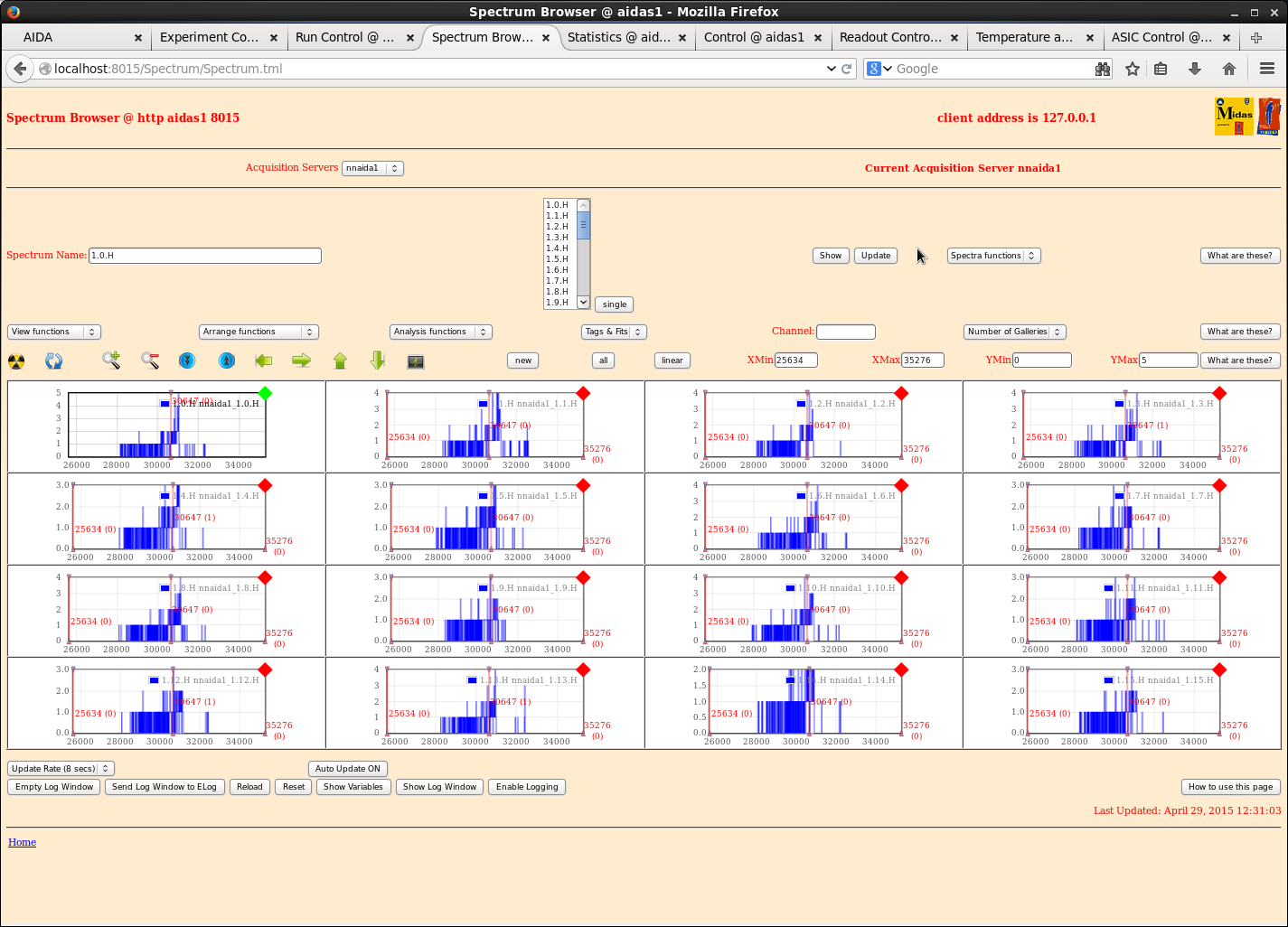
|
| Attachment 10: 20150429_nnaida2_det2_H.png
|
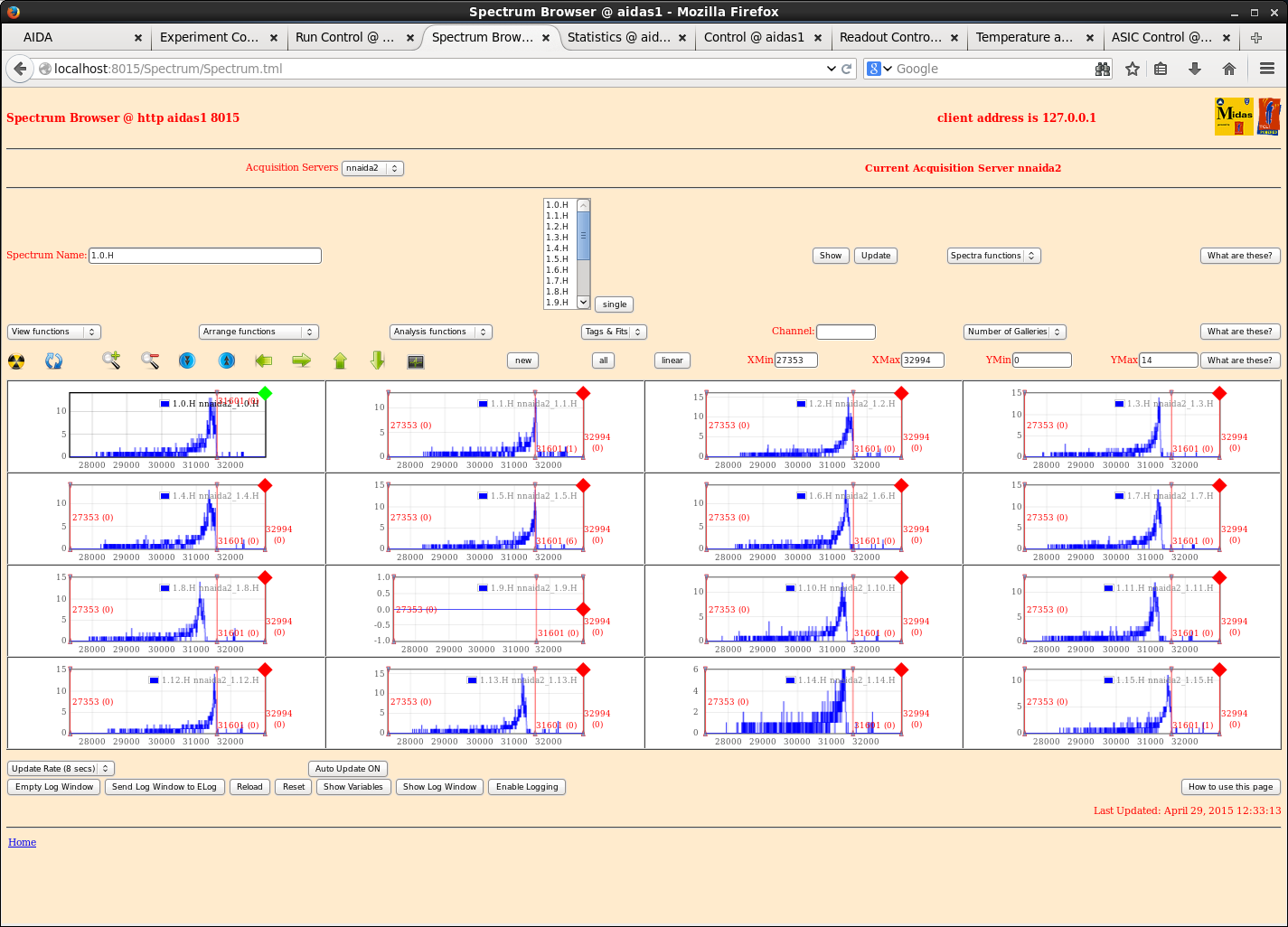
|
| Attachment 11: 20150429_nnaida4_det2_H.png
|
|
| Attachment 12: 20150429_nnaida8_det3_H.png
|
|
| Attachment 13: 20150429_nnaida10_det1_H.png
|
|
| Attachment 14: 20150429_nnaida16_det1_H.png
|
|
| Attachment 15: 20150429_dataReadout_nnaida4.png
|
|
| Attachment 16: 20150429_datrareadout_nnaida3.png
|
|
|
|
87
|
Thu Apr 30 16:20:54 2015 |
JA, LHB, TD, AE, CG & VP | Friday 1 May 2015 |
      diode link threshold 0xca -> 0xb6
                           0x11 -> 0x2c

00.20 R31
      1mm + 1.4mm Al degrader
00.42 R31 ends

      R32
      -1mm Al degrader
00.54 R32 ends

Data indicates changes to diode link threshold is 'switching off' decay p+n strip events,
n+n strips appear to be less affected

01.00 R33
      diode link threshold 0xca -> 0xbf
                           0x11 -> 0x23

      ASIC parameters saved to /MIDAS/DB/EXPERIMENTS/AIDA/2015Apr30-diode-mod2

Ignore R34 & R35

09.40 Fast LEC/MEC discriminators disabled:
     Mask bits 31->0, 63->32 *not* 0->31 and 32->63 as implied by Disc Controls window

         Chan                 Mask
                             31->0      63->32
nnaida1                        0x0   0x4000000
nnaida2  ch 22, 26       0x4400001   0x8000000
nnaida6  ch  1                 0x2         0x0
nnaida9  ch 45 "               0x0      0x2000
nnaida10 ch 31 "        0x82000000  0x80000000
nnaida11 ch 55 "               0x0    0x800000
nnaida13                       0x0   0x4000000
nnaida16 ch 55 "               0x0    0x800000

Local Controls -> Timing O/P Control Register 0xc -> 0xe (OR64) https://elog.ph.ed.ac.uk/AIDA/79

09.48 R36
      BigRIPS 110Zr setting
      Degrader ?
10.43 R36 ends
      Beam off for ion source re-tune

10.50 nnaida6 good events c. 250k, c. 20Hz PAUSE/RESUME
      change slow comparator 0x14 -> 0x20
      rate/channel ~5kHz -> ~1kHz

      ASIC parameters saved to /MIDAS/DB/EXPERIMENTS/AIDA/2015Apr30-diode-mod2

12.00 VFEP updates
      DataAcquisitionControl.tcl and sys.tcl

      Fast comparator masks are now saved
      MACB trigger mode default 0xe (OR64) and can be saved as a setting

      Stop/Go logic altered so that electronics data generation is the last to be GOED and first to be STOPPED

12.10 Beam back

12.13 R38 |
|
|
71
|
Sat Apr 25 03:56:44 2015 |
JA, LHB, TD, AE & CG | Saturday 25 April 2015 |
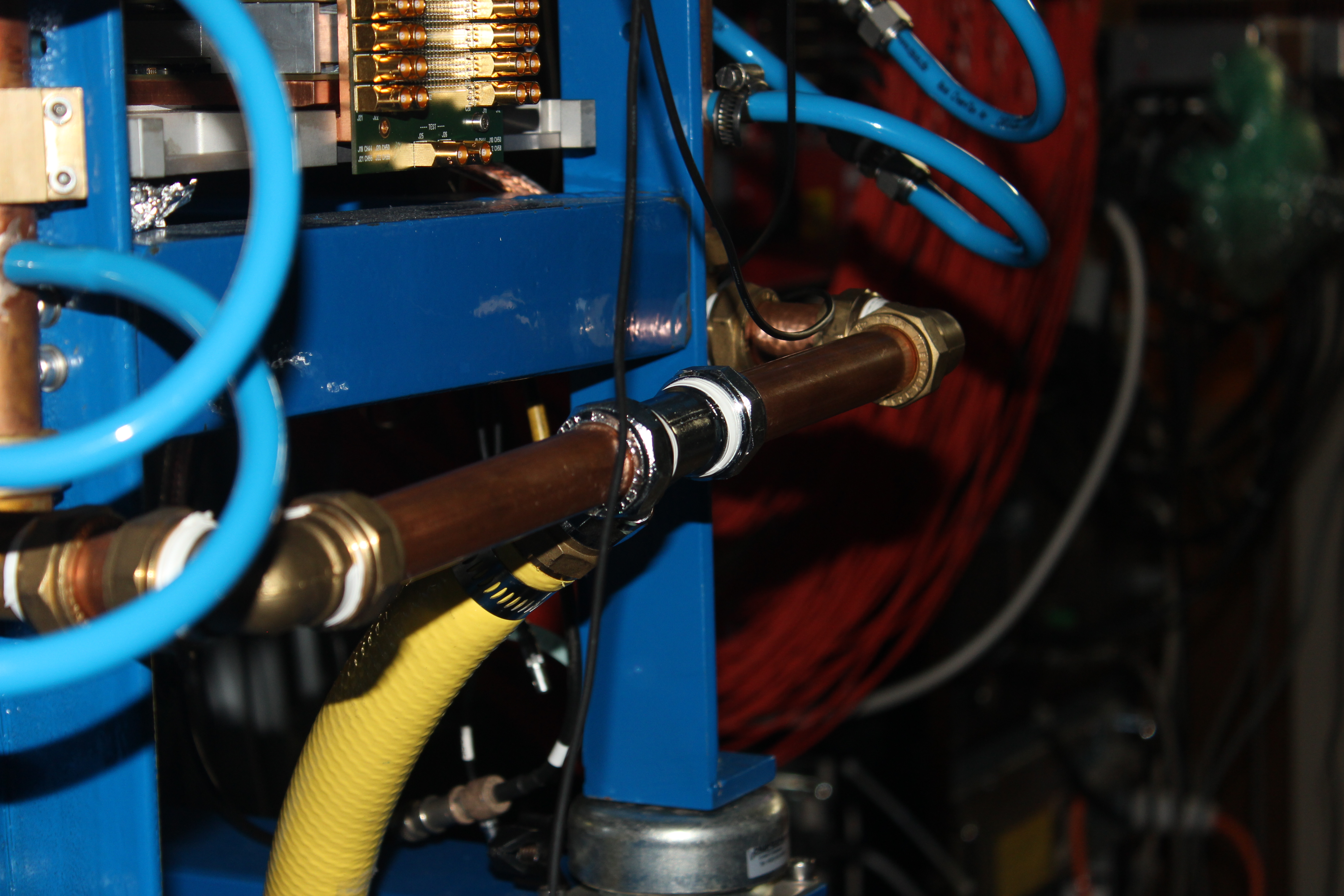
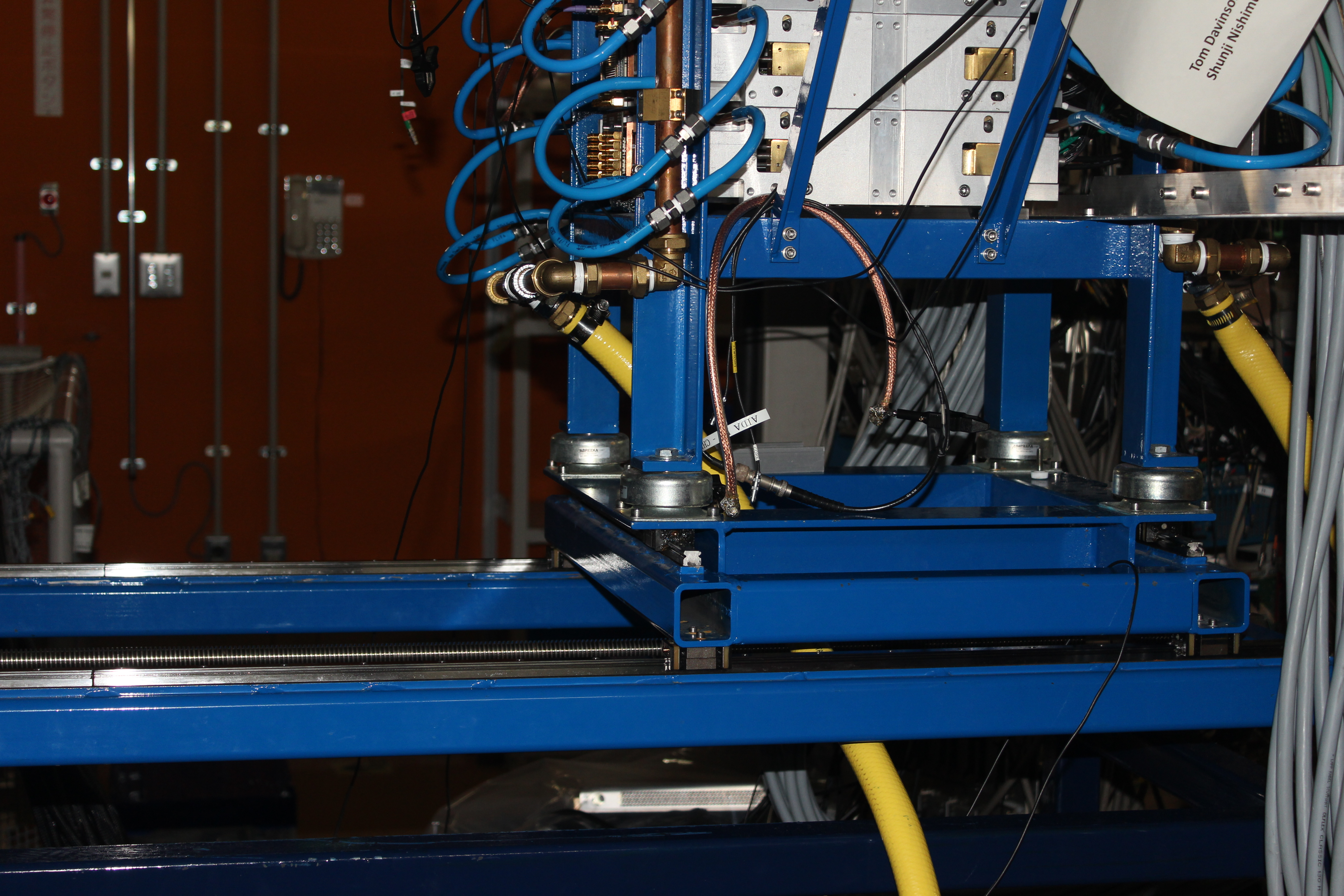
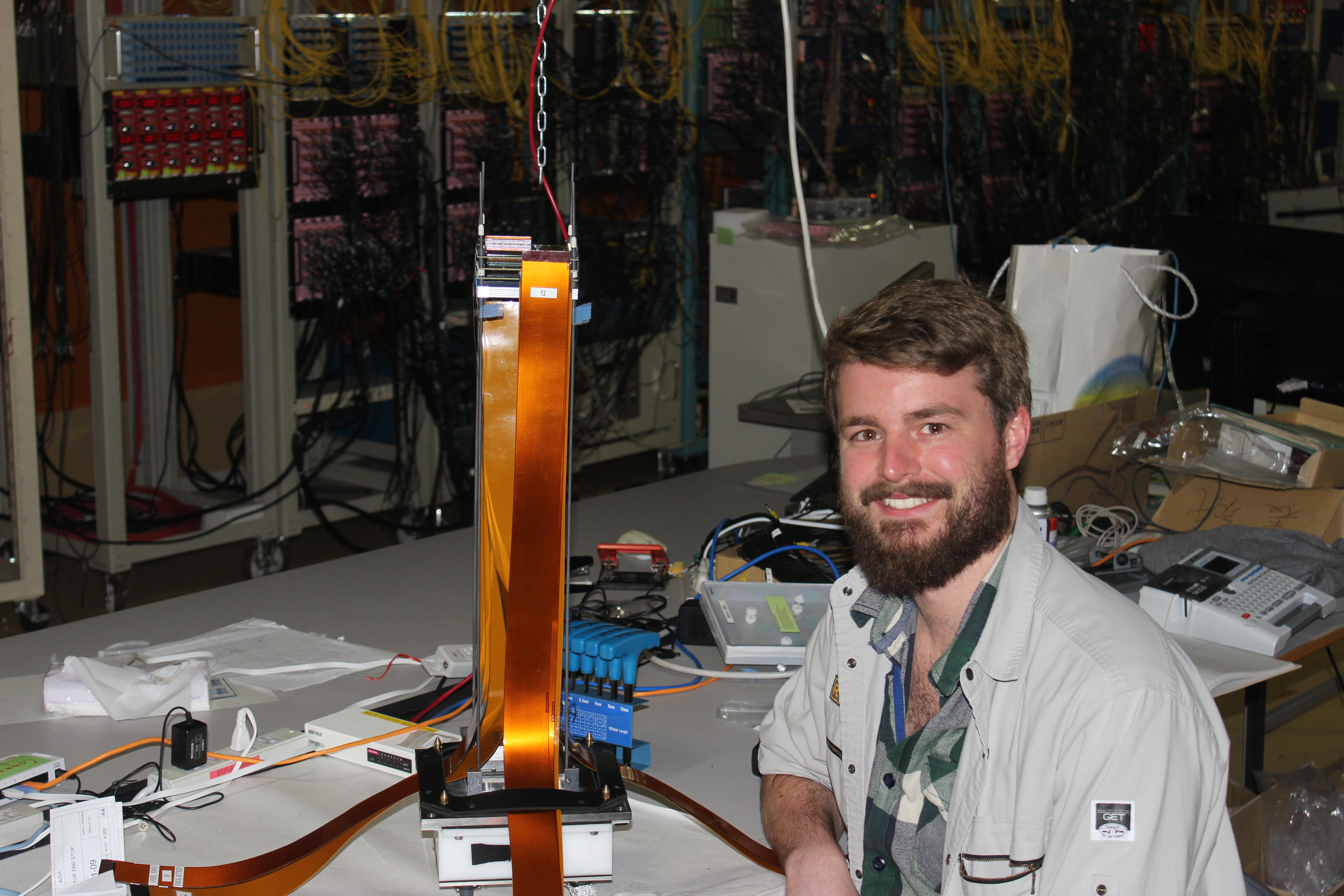
1130: Rotated forward water inlet connection to point towards rear of AIDA stand to remedy mechanical
      conflict with EURICA support frame - see attachments. During drain and re-fill of Julabo FL1106
      recirculating chiller no evidence of sediment in, or discoloration of, the water. Coolant loop closed
      and tested OK.

      CG installing (new, production batch) second and third MSL type BB18(DS)-1000 detectors to stack using
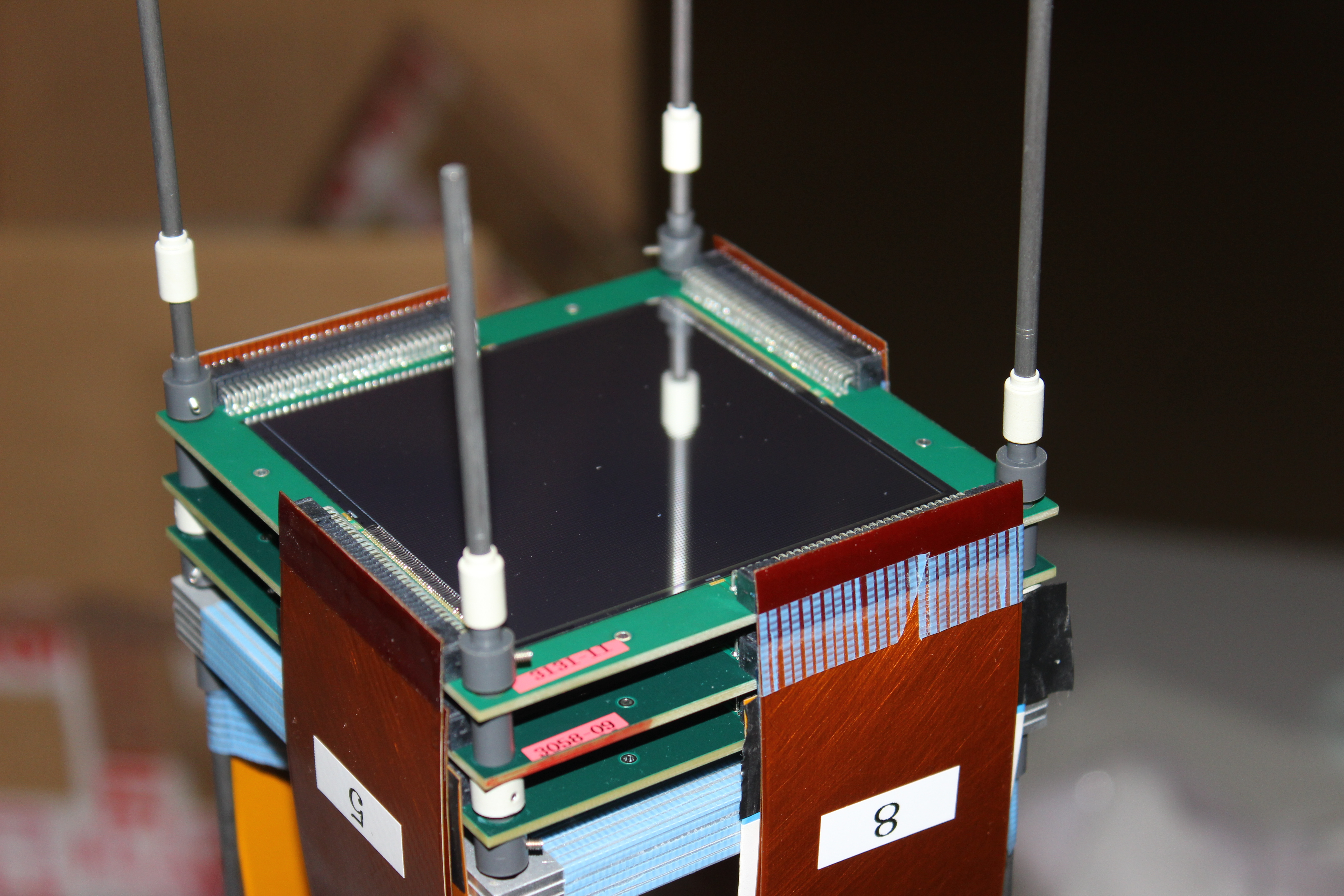
      the new FCT reduced capacitance 0.9m, 68-way to 68-way, flexible Kapton PCBs - see attachments.

1200: Installed two new BB18 detectors (3131-11 and 3058-09) to nose mount.
      Modified isolated kaptons labelled and number 1 and 5.
      Source (207Bi) mounted upstream of first detector approx 5-10mm away.

      Configuration - 3131-11 (#1) furthest upstream, 3058-09 (#2) in middle, 2977-20 (#3) at rear, followed by
10mm of Al.

1800: Cabled everything up.
      3131-11 connected to nnaida10+6 (p-side) and nnaida11+16 (n-side). HV from single supply.
      3058-09 connected to nnaida2+5 (p-side) and nnaida4+7 (n-side). HV from ch0 of quad supply.
      2977-20 connected to nnaida1+14 (p-side) and nnaida3+8 (n-side). HV from ch1 of quad supply.

      Typical resistance of new kaptons ~6.5 ohm.
      Typical resistance of old kaptons ~3.2 ohm.
      Makes sense if track width has been roughly halved, doubling resistivity.

      At +100V bias:
         - 3131-11 has leakage current 5.88 uA.
         - 3058-09 has leakage current 3.82 uA.
         - 2977-20 has leakage current 10.99 uA.

2000: Carried out brief pulser test of all connected modules.
      Many spectra exhibit double-peaking of the pulser peak or otherwise non-Gaussian peaks.
Of the ones the have single Gaussian shaped peaks, many now have much larger FWHM than previously observed. |
| Attachment 1: IMG_2852.JPG
|
|
| Attachment 2: IMG_2853.JPG
|
|
| Attachment 3: IMG_2858.JPG
|
|
| Attachment 4: IMG_2860.JPG
|
|
|
|
72
|
Sun Apr 26 02:28:59 2015 |
JA, LHB, TD, AE & CG | Sunday 26 April 2015 |
Upstream, 207Bi source

DSSSD #1  nnaida 6  & 9  (p+n), nnaida 11 & 16 (n+n)

DSSSD #2  nnaida 2  & 5  (p+n), nnaida 4  & 7  (n+n)

DSSSD #3  nnaida 1  & 14 (p+n), nnaida 3  & 8  (n+n)

N/C       nnaida 10 & 13 (p+n), nnaida 12 & 15 (n+n)

3x MSL type BB18(DS)-1000 DSSSDs connected via 12x flexible Kapton PCB cables to 8x adaptor PCBs


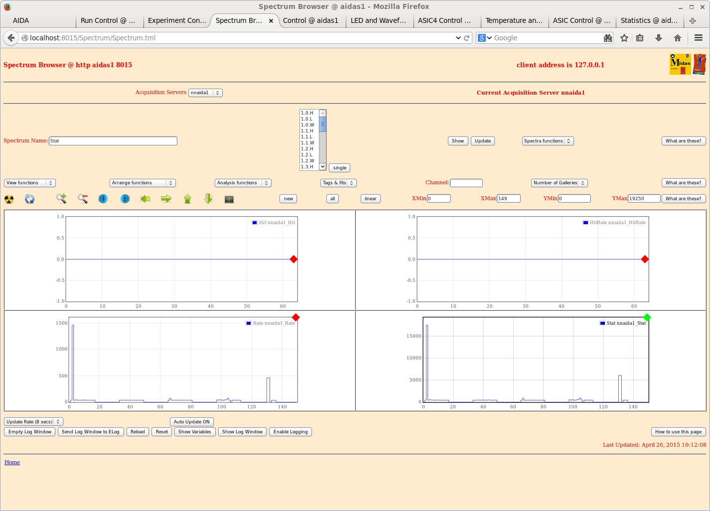
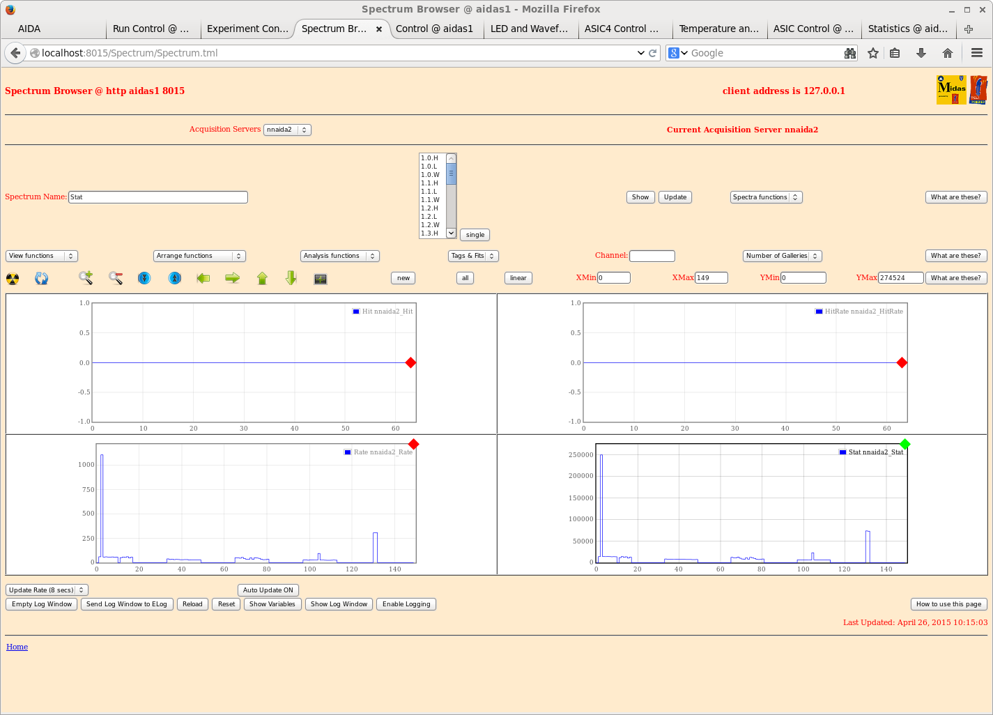
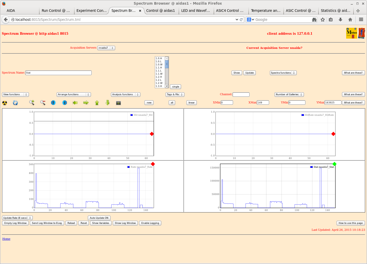
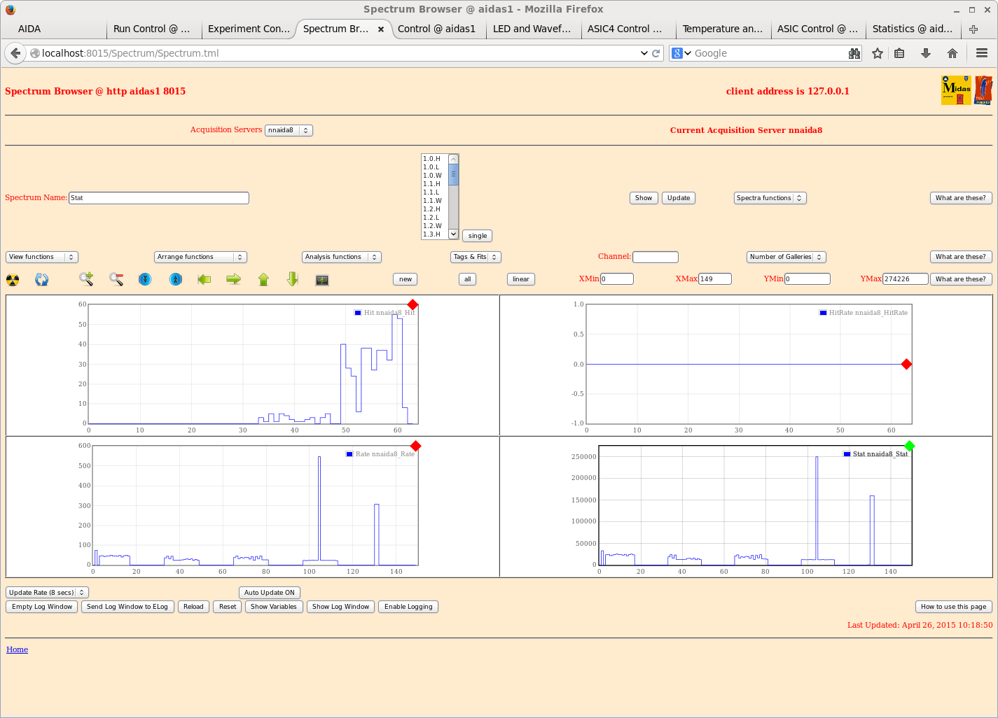
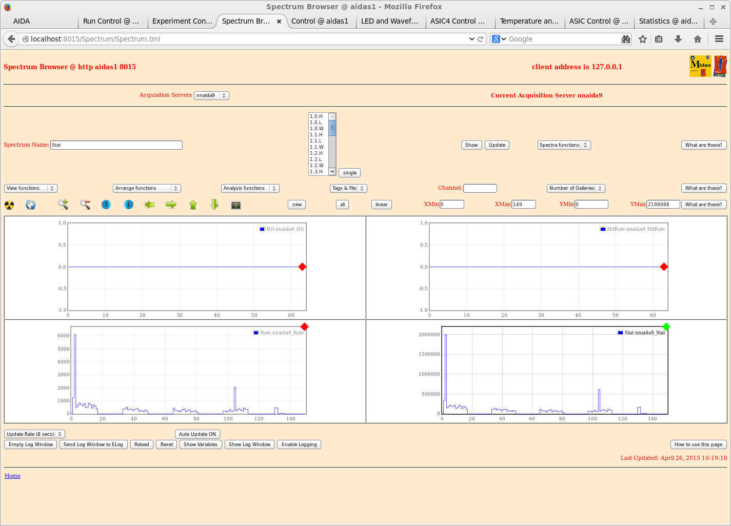
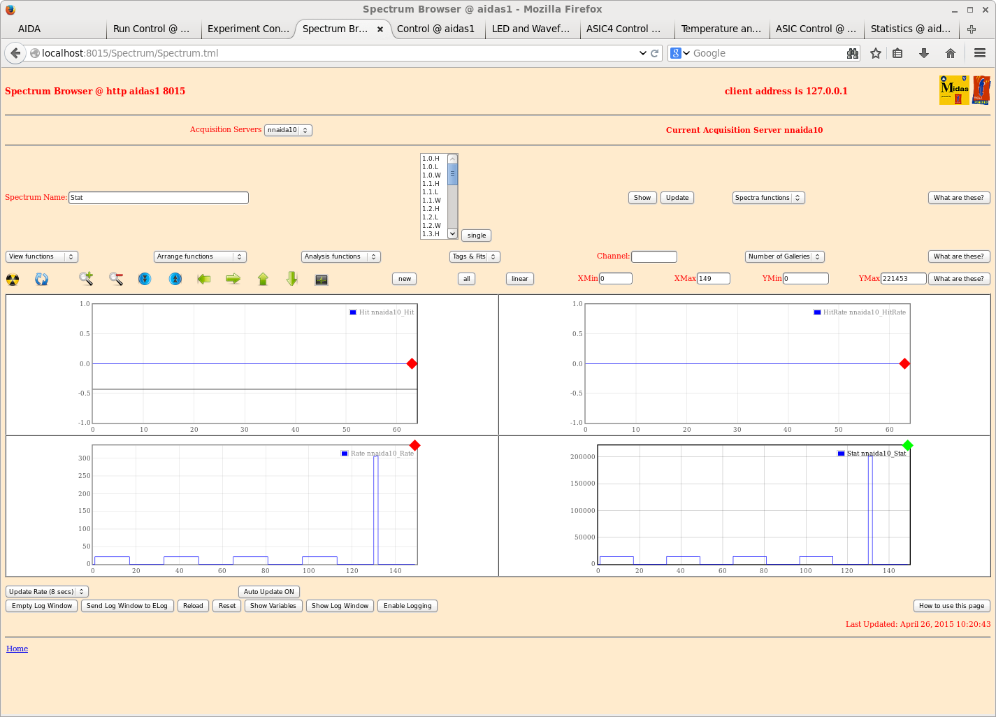
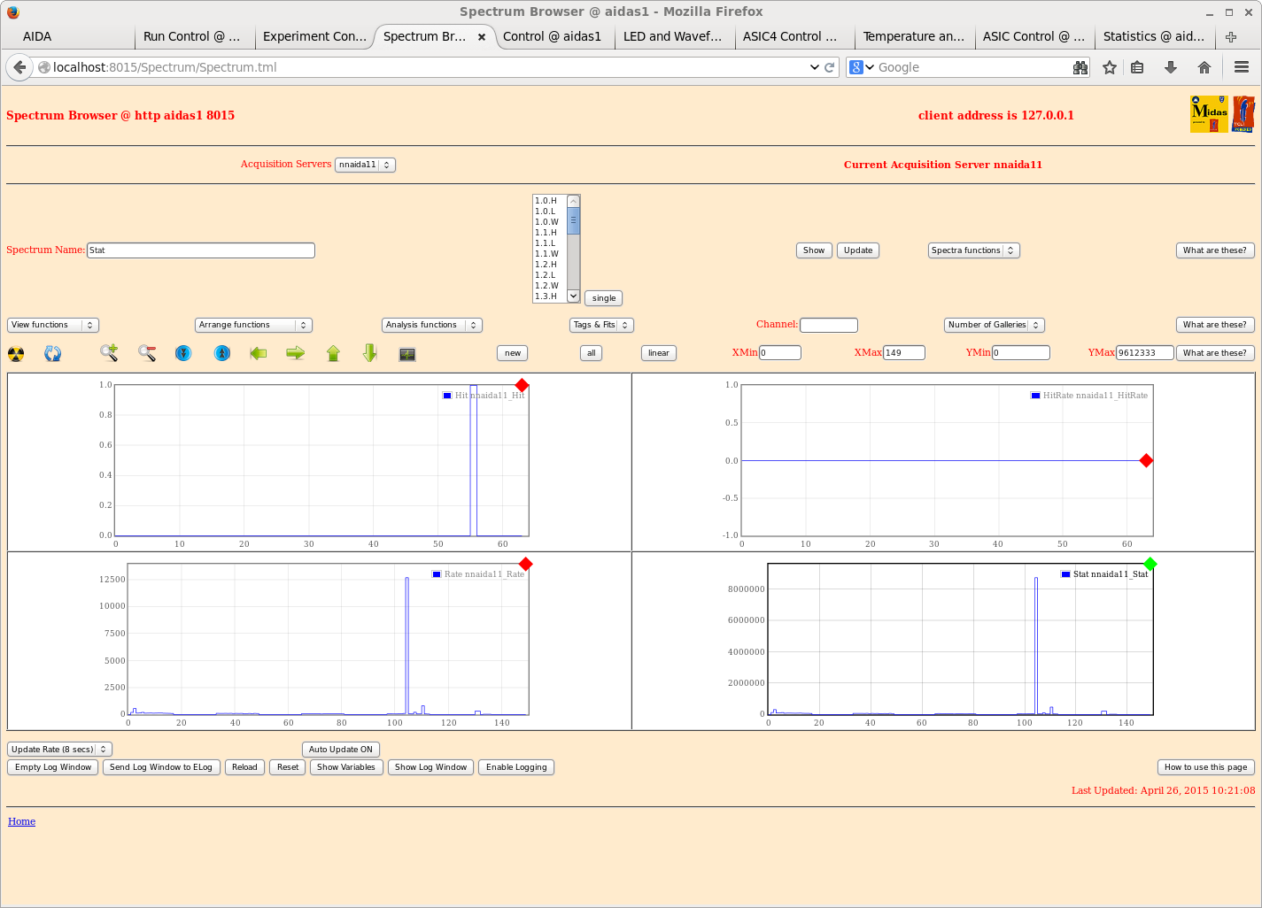
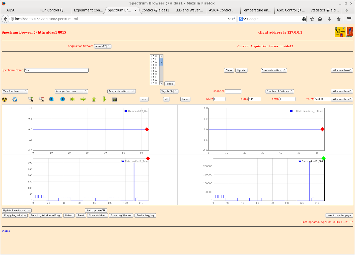
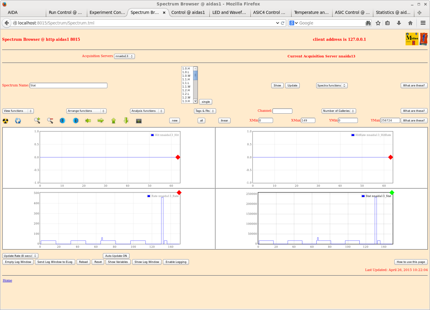
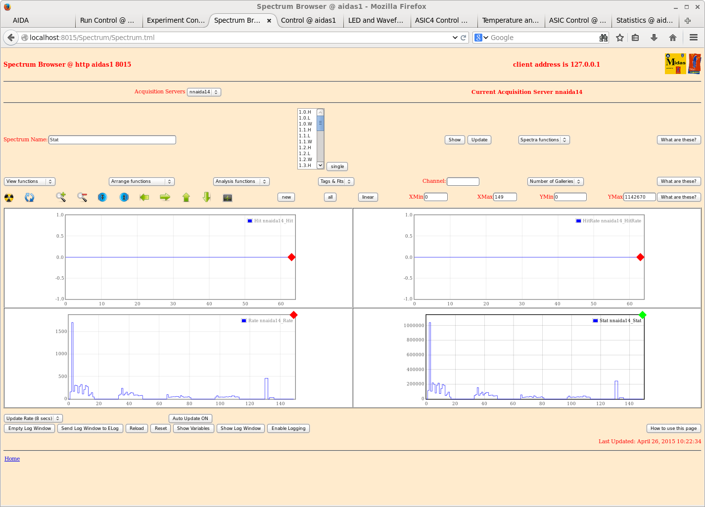
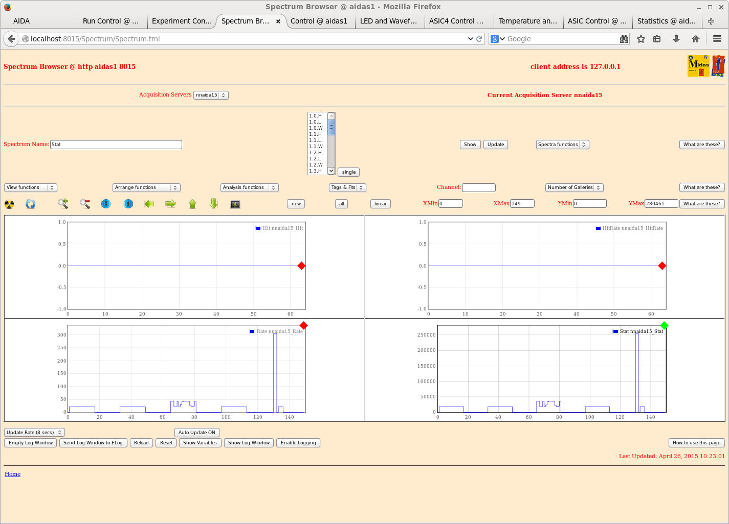
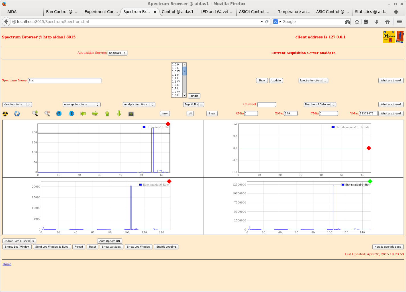
Hit patterns show attachments 1-16


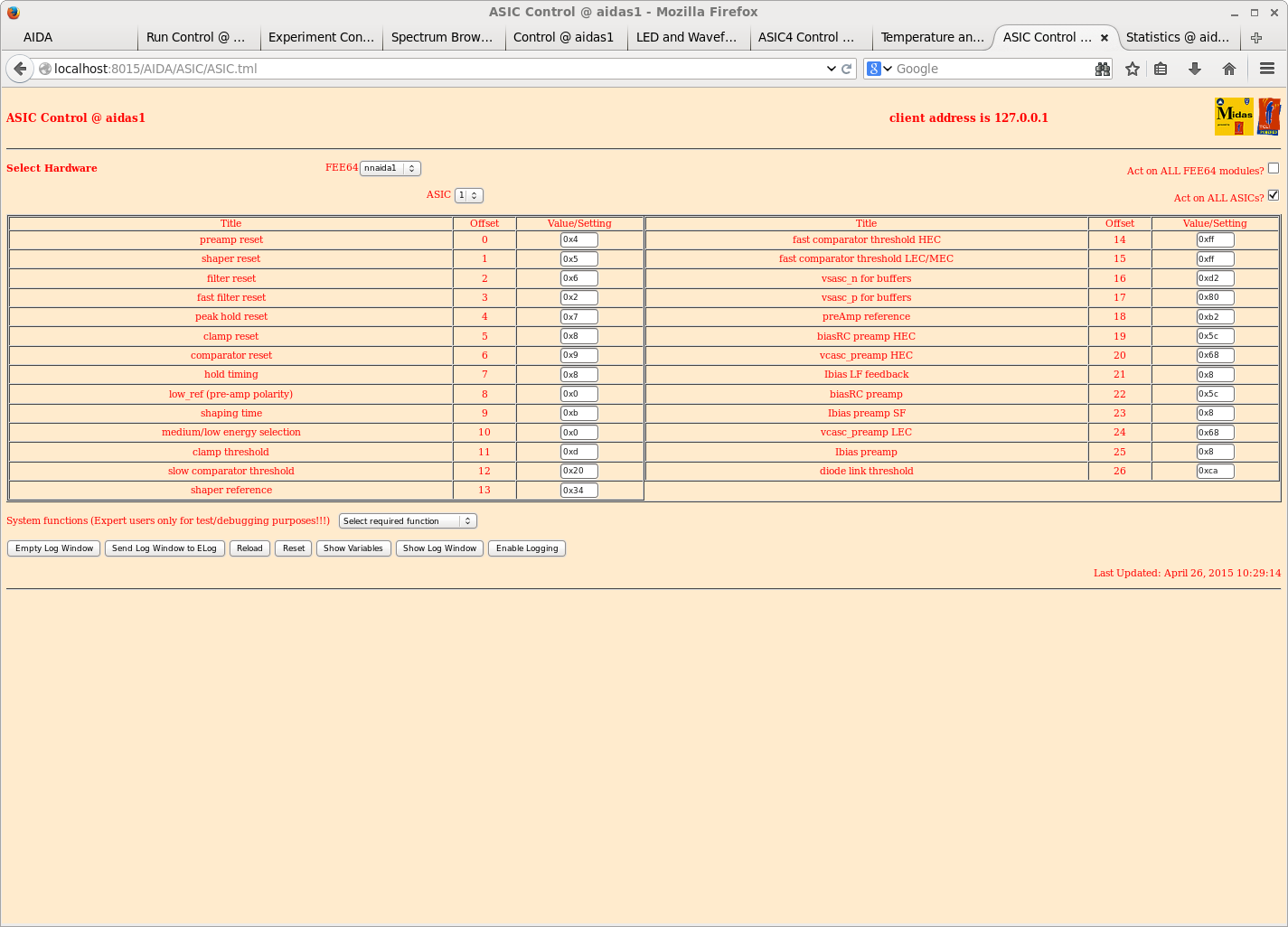
Default ASIC parameters *except* slow comparator 0x10 -> 0x20

Example ASIC configuration attachment 17

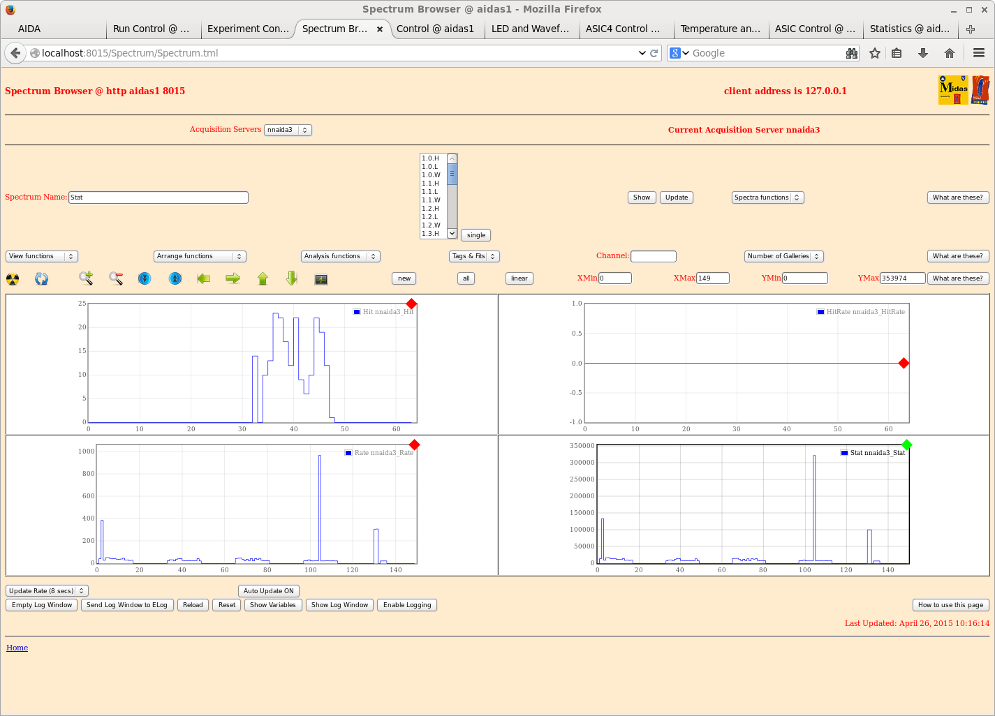
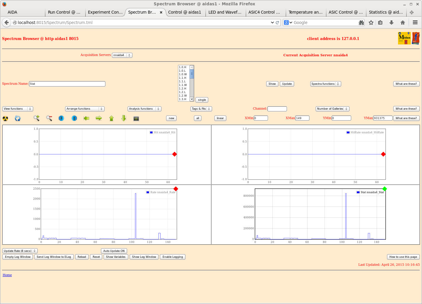
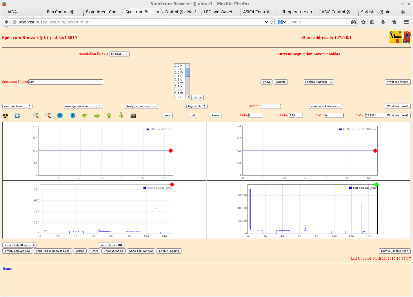
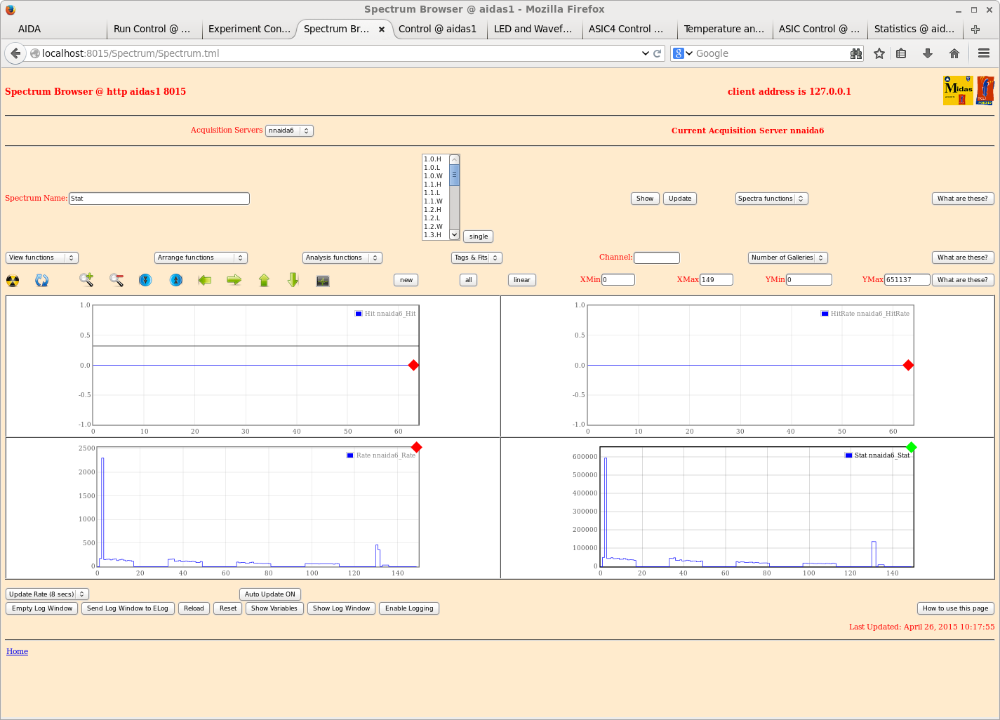
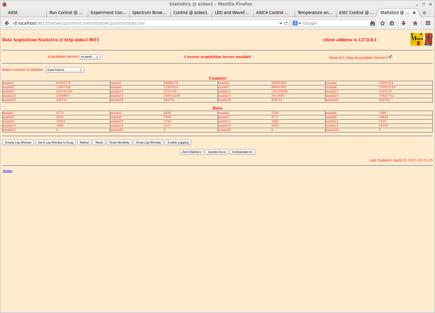
Example 'Good Events' statistics attachment 18


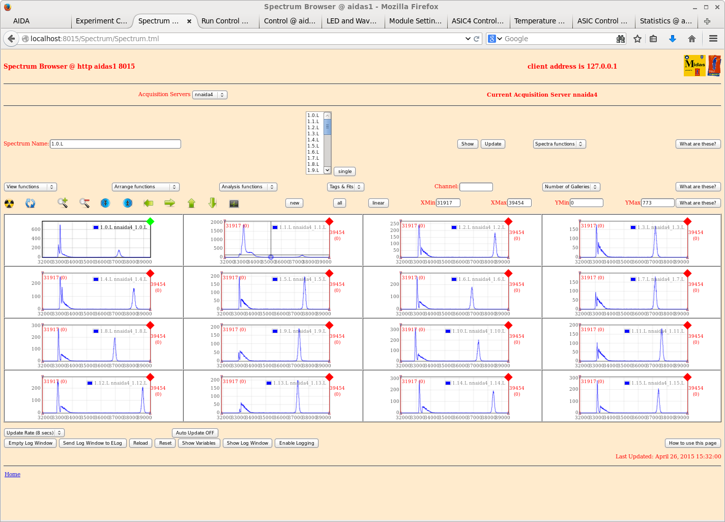
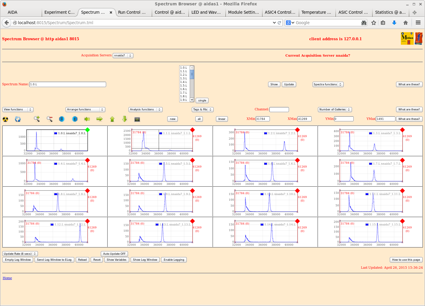
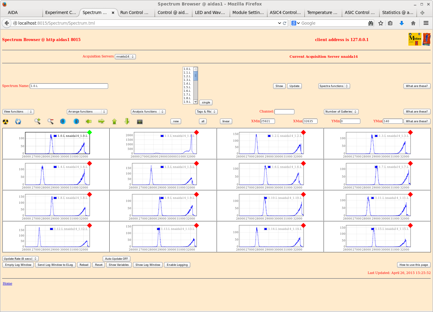
ASIC #1 waveforms of nnaida 1 - 16 enabled

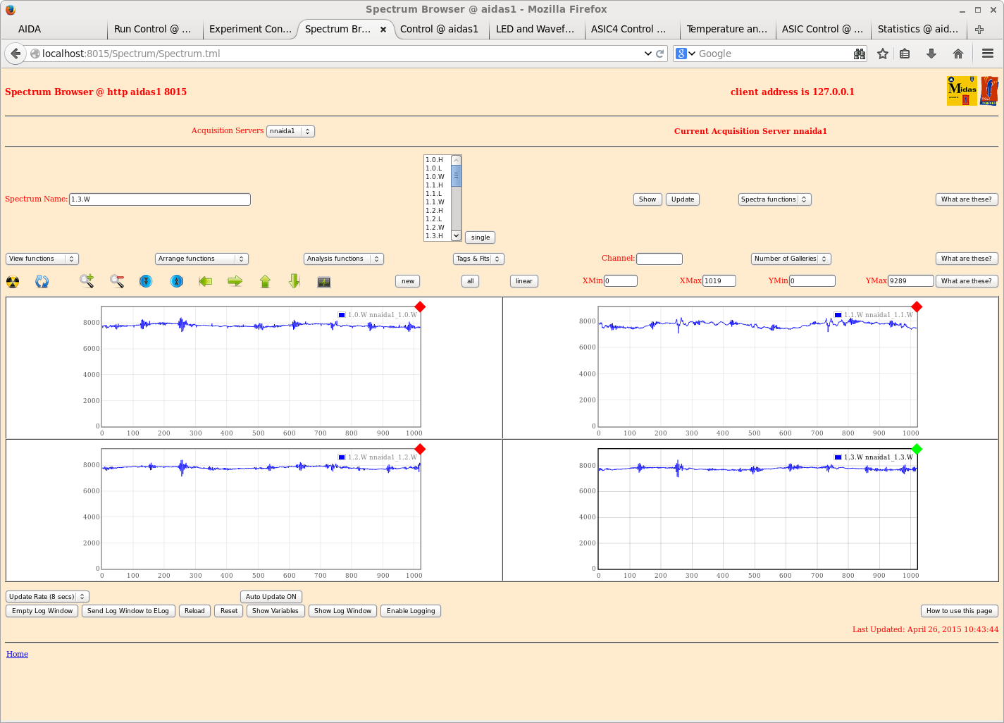
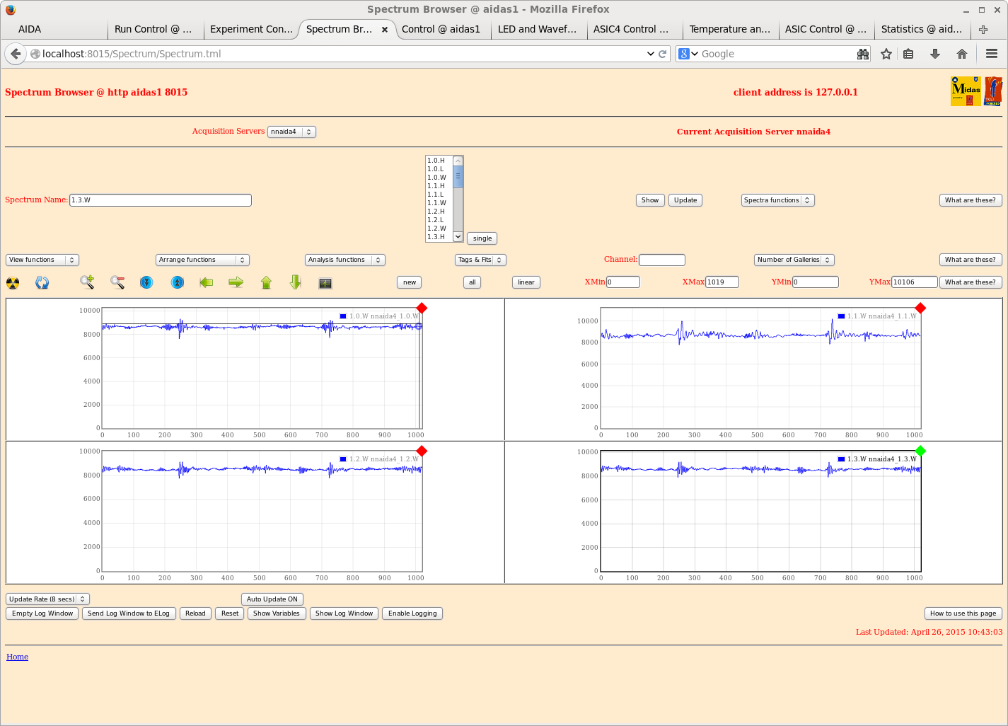
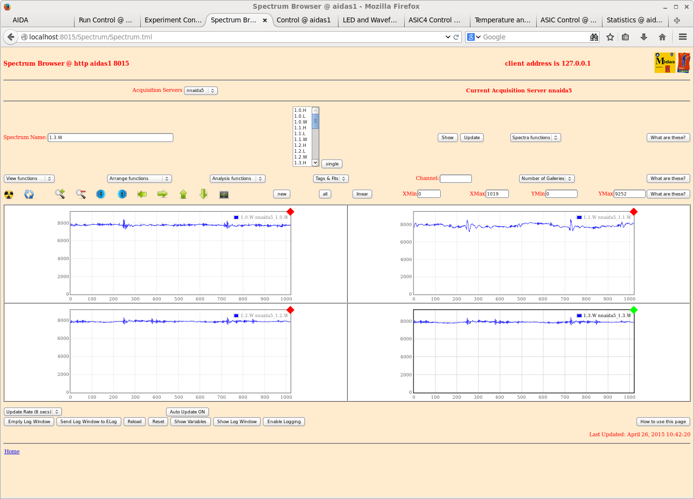
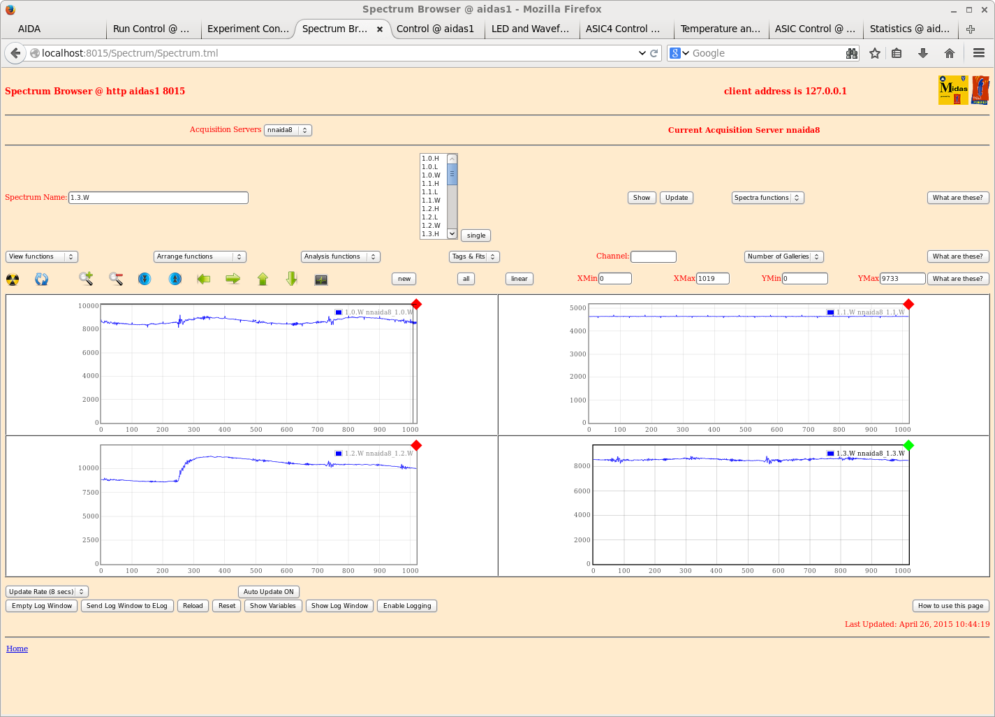
Example waveform for p+n and n+n strips of each DSSSD attachments 19-24


Parameters saved to: /MIDAS/DB/EXPERIMENTS/AIDA/2015Apr26-10.56.40


12.10 Removing bias gnd jumper from p+n adaptor PCBs increases amplitude of ~100kHz RFI/EMI
      (attachment 25)

15.20 Reduce DSSSD configuration to 1x DSSSD using 4x adaptor PCBs + heavy duty copper braid
      DSSSD #2 nnaida 2 & 14 (p+n), nnaida 4 & 7 (n+n)

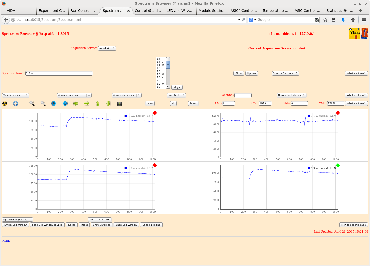
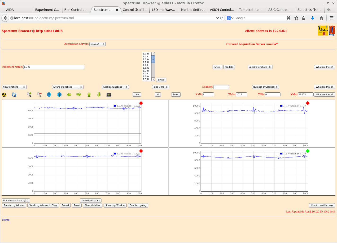
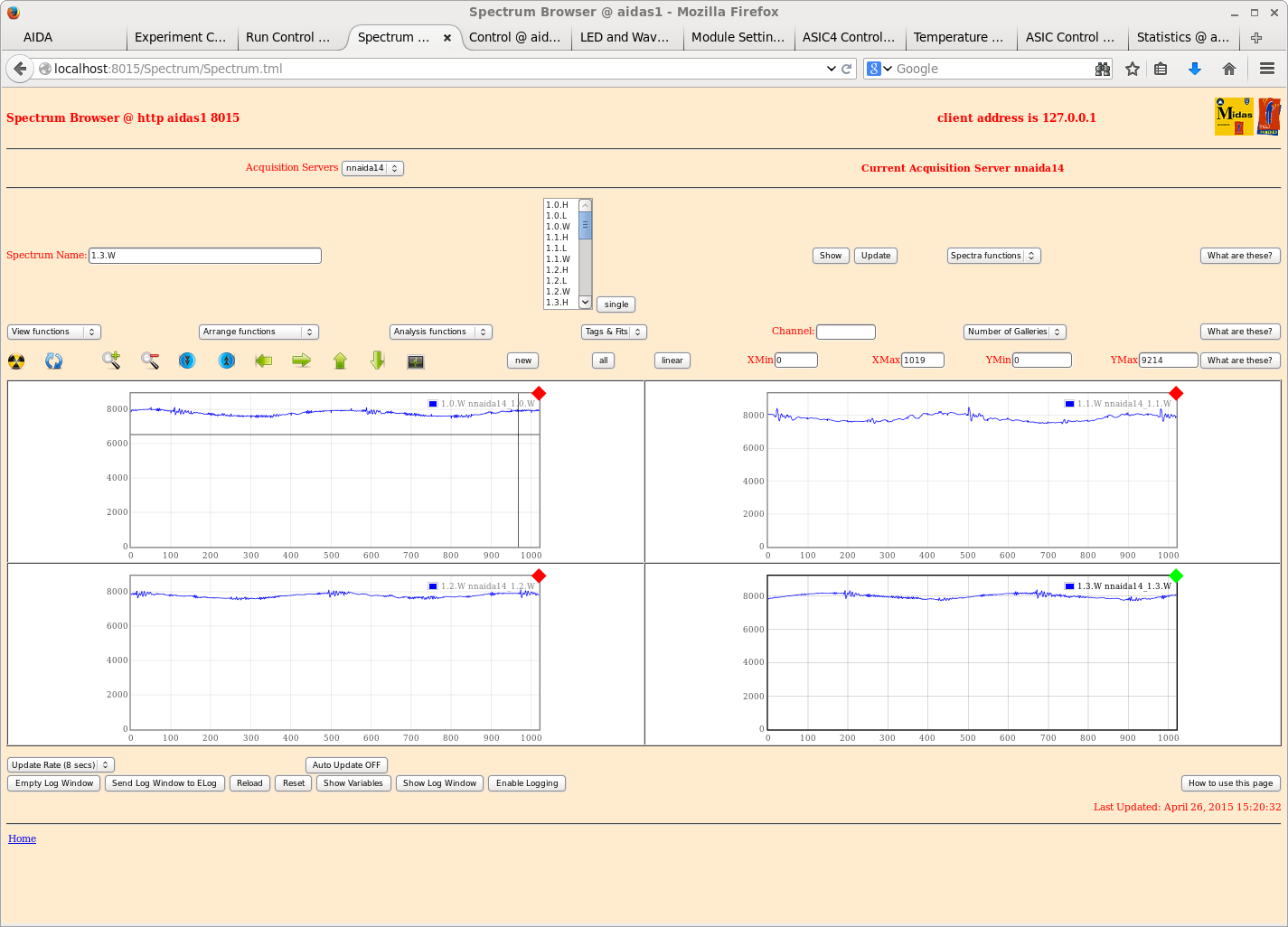
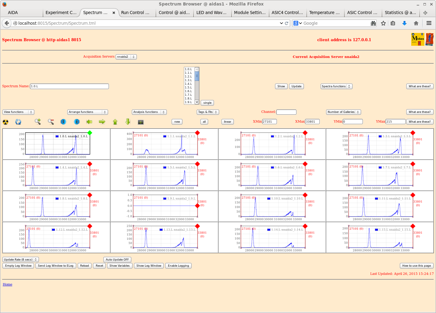
      attachments 26-33 show example preamp traces and ASIC#1 spectra

      similar stability/performance to previous tests with a single DSSSD, typical pulser
      peak widths ~130-200 ch FWHM

      AIDA snout drain wire - no obvious difference if connected, or not (as before)

15.40 DSSSD configuration 2x DSSSD using 8x adaptor PCBs
      DSSSD #2 nnaida 2 & 14 (p+n), nnaida 4 & 7 (n+n) + heavy duty copper braid
      DSSSD #1 nnaida 6 & 10 (p+n), nnaida 11 & 16 (n+n) + black jumper cables from above adaptor PCBs
      to these adaptor PCBs
      Detector bias from N1419 and N1419B, i.e. separate NIM modules => separate floating grounds
      similar or improved performance to 1x DSSSD test, typical pulser peak widths ~115-250 ch FWHM

16.15 CG smartphone camera pictures of front end config

16.30 data to disk - file /Tapedata/May2015/R3_0.gz (BNC Pb-4 25Hz + 207Bi source)

17.30 Detector bias from N1419, i.e. both detector biases from same NIM module => same floating ground
      for both DSSSDs

      Similar performance to case above (separate NIM modules)

17.46 data to disk - file /Tapedata/May2015/R4_0.gz (BNC Pb-4 25Hz + 207Bi source) |
| Attachment 1: 1.png
|
|
| Attachment 2: 2.png
|
|
| Attachment 3: 3.png
|
|
| Attachment 4: 4.png
|
|
| Attachment 5: 5.png
|
|
| Attachment 6: 6.png
|
|
| Attachment 7: 7.png
|
|
| Attachment 8: 8.png
|
|
| Attachment 9: 9.png
|
|
| Attachment 10: 10.png
|
|
| Attachment 11: 11.png
|
|
| Attachment 12: 12.png
|
|
| Attachment 13: 13.png
|
|
| Attachment 14: 14.png
|
|
| Attachment 15: 15.png
|
|
| Attachment 16: 16.png
|
|
| Attachment 17: 17.png
|
|
| Attachment 18: 18.png
|
|
| Attachment 19: 1w.png
|
|
| Attachment 20: 4w.png
|
|
| Attachment 21: 5w.png
|
|
| Attachment 22: 8w.png
|
|
| Attachment 23: 9w.png
|
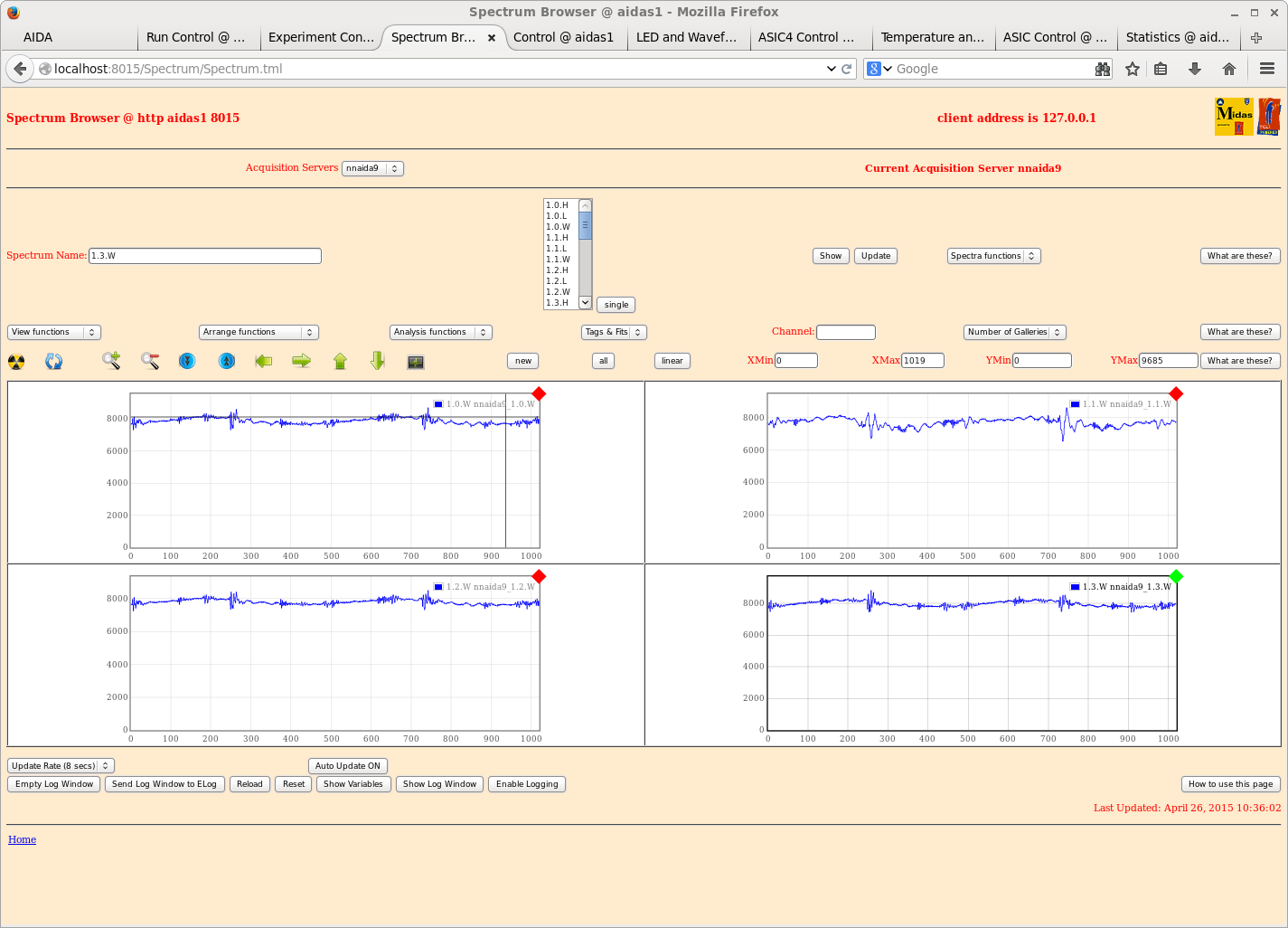
|
| Attachment 24: 11w.png
|
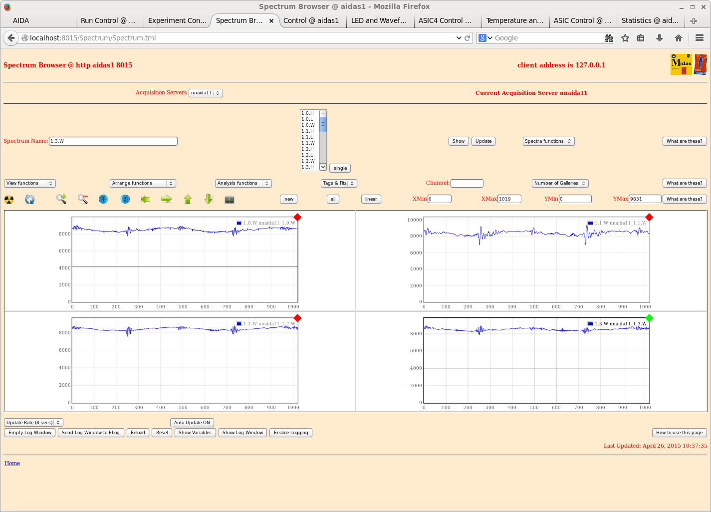
|
| Attachment 25: 9w-bias-jumper.png
|
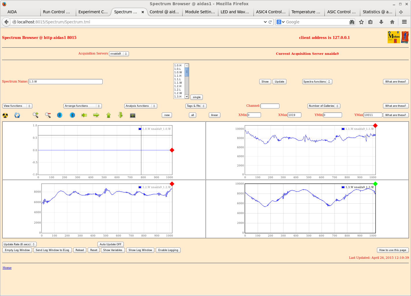
|
| Attachment 26: 2w-1.png
|
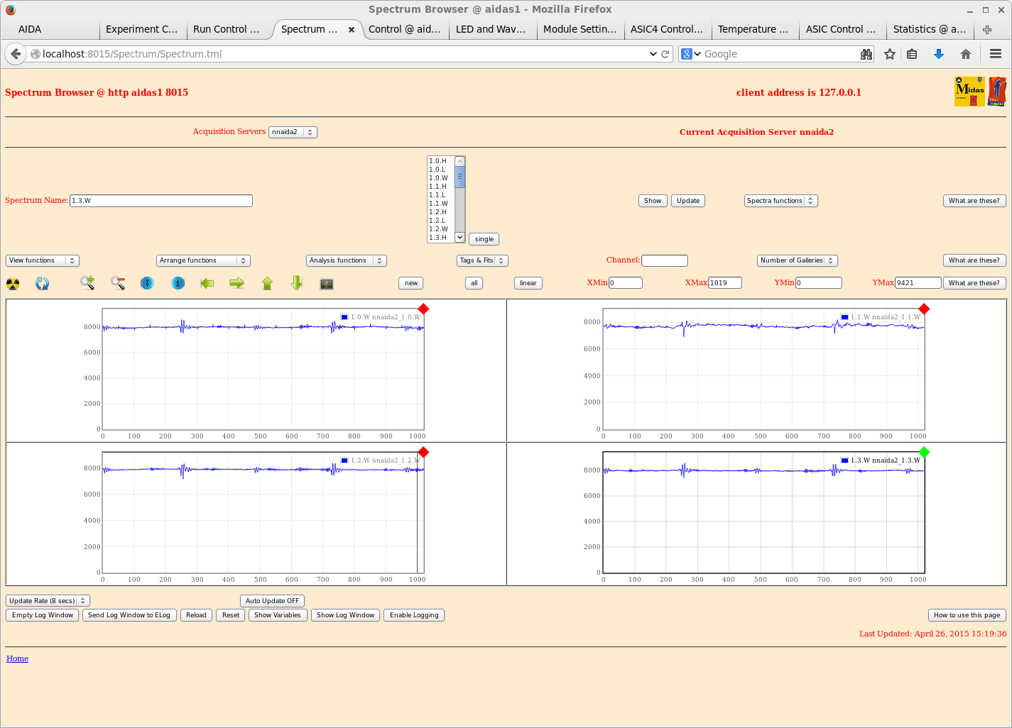
|
| Attachment 27: 4w-1.png
|
|
| Attachment 28: 7w-1.png
|
|
| Attachment 29: 14w-1.png
|
|
| Attachment 30: 2-1.png
|
|
| Attachment 31: 4-1.png
|
|
| Attachment 32: 7-1.png
|
|
| Attachment 33: 14-1.png
|
|
|
|
76
|
Tue Apr 28 06:25:13 2015 |
JA, LHB, TD, AE & CG | Tuesday 28th April progress |
28/04/15
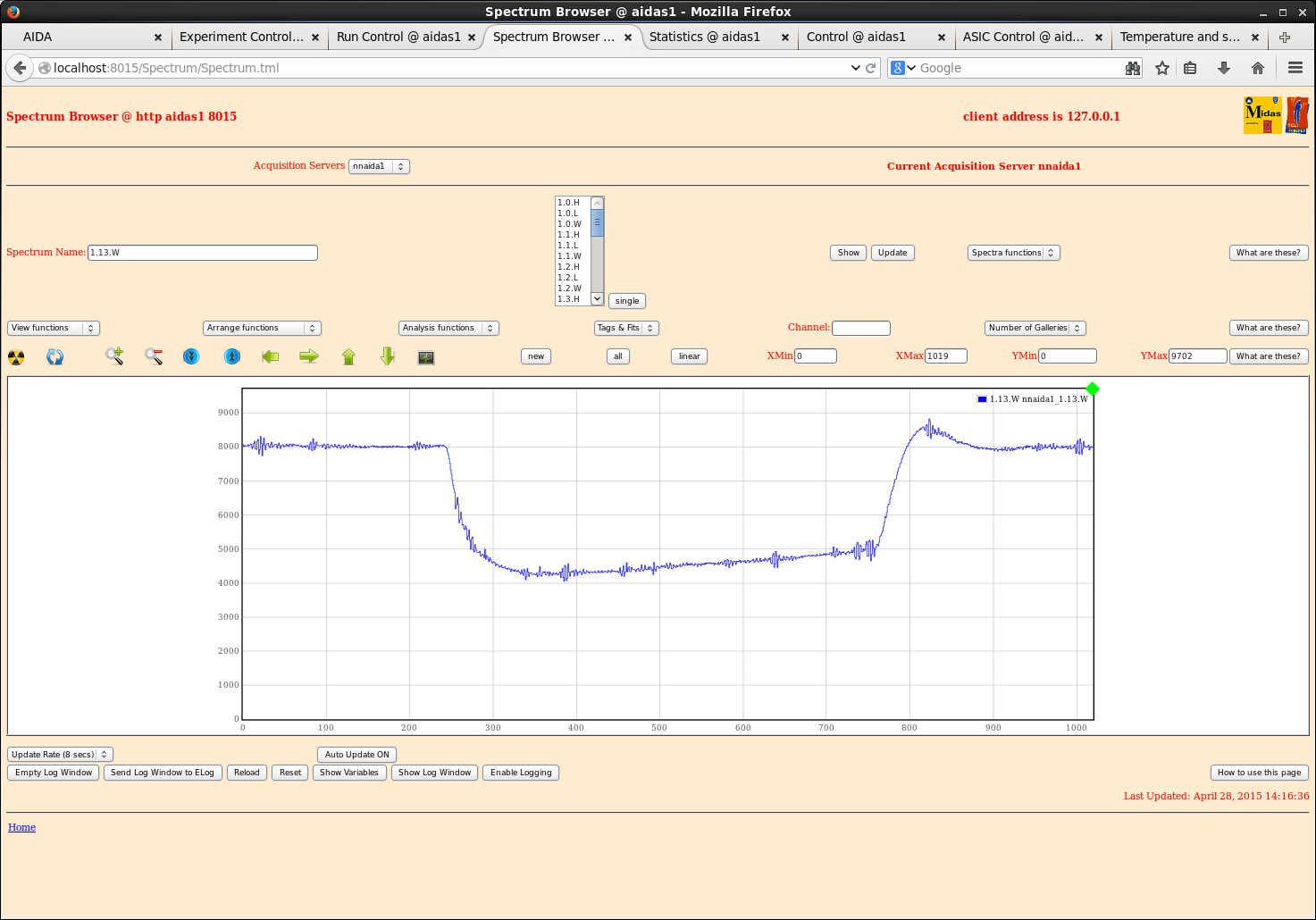
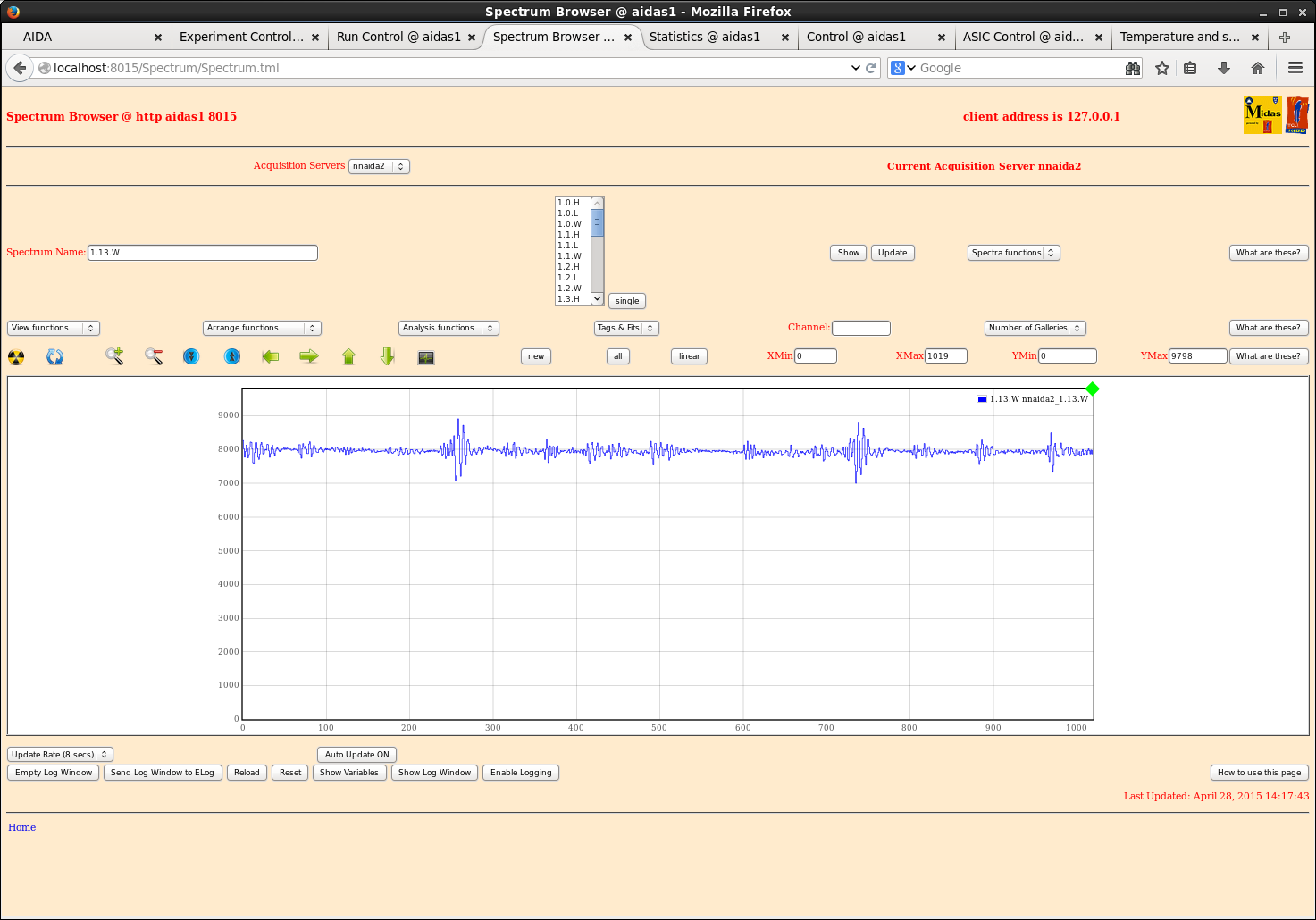
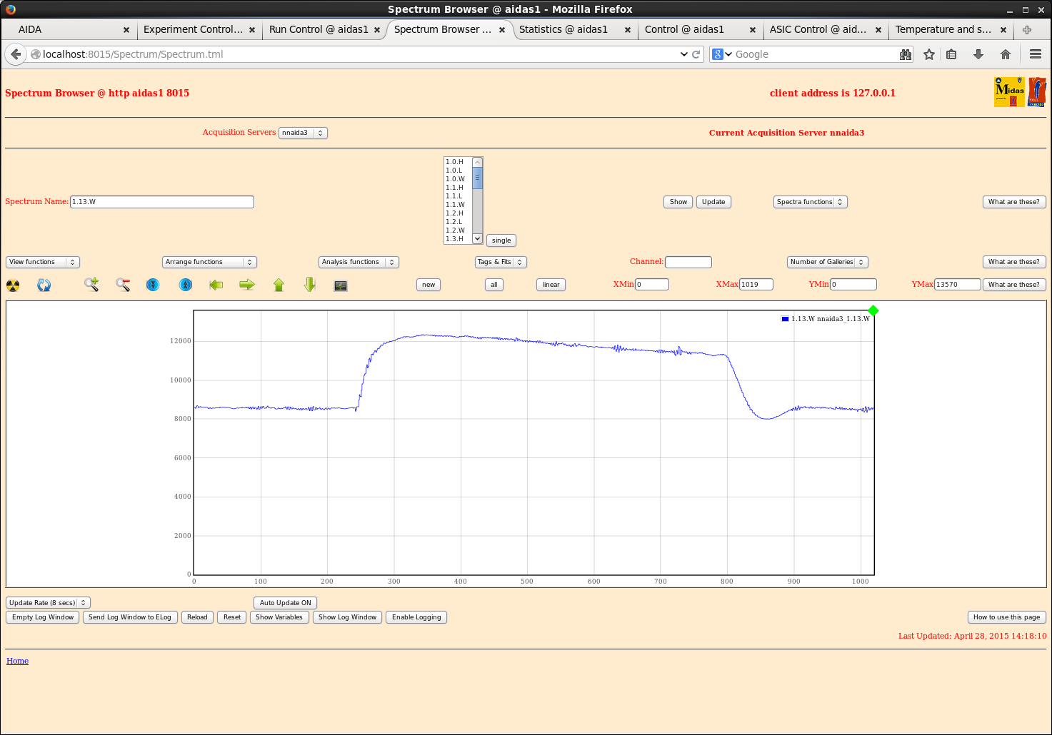
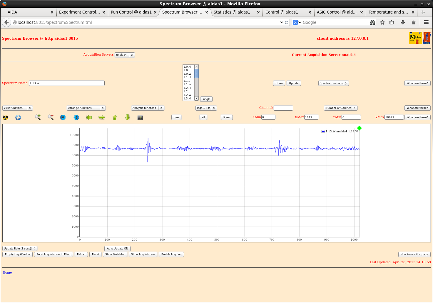
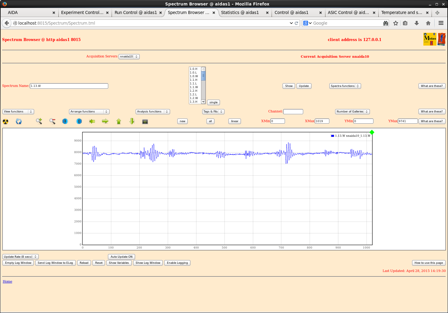
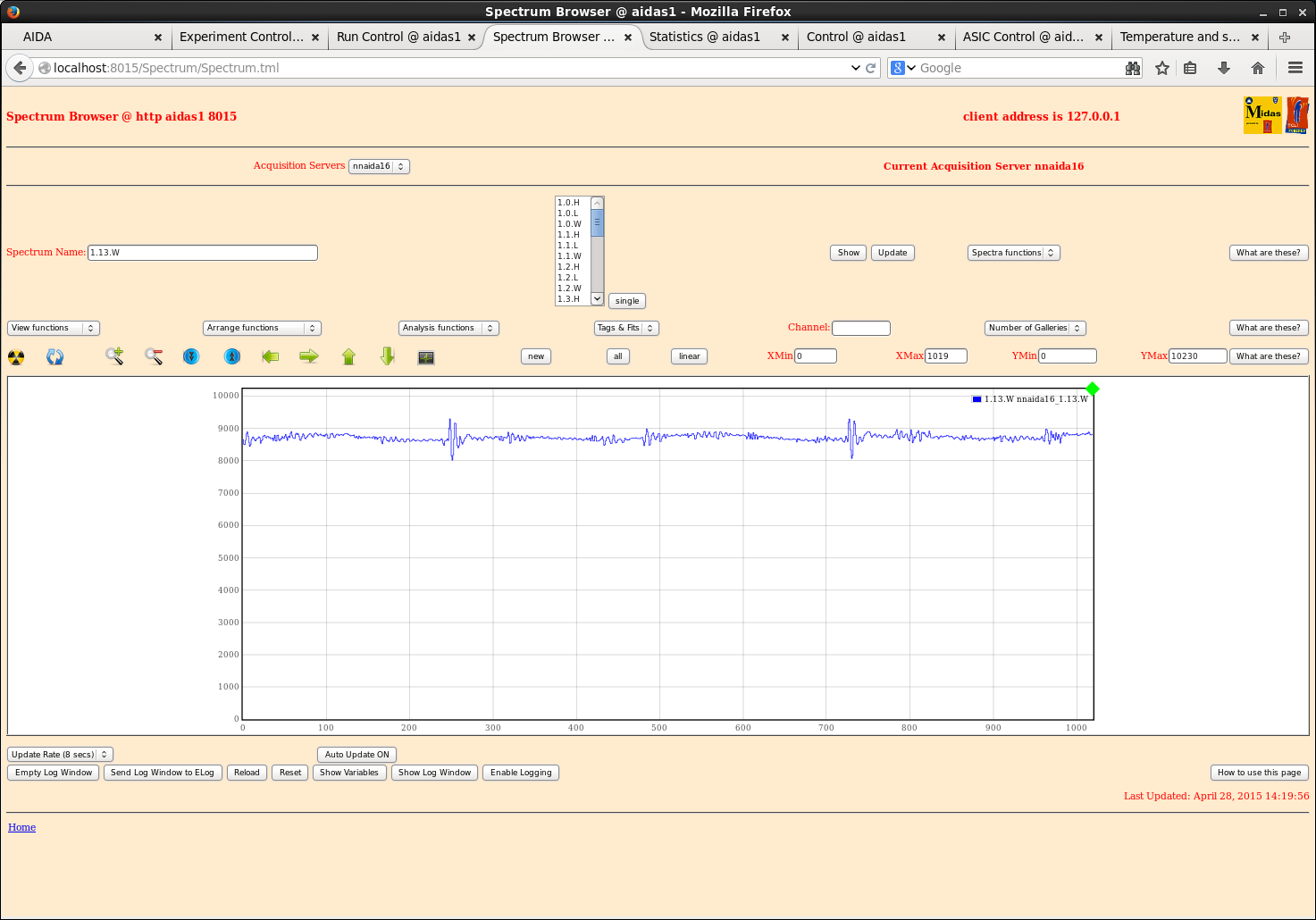
1420: Carried out ASIC optimisation tests to find best shaping time. Chose system wide shaping time of 0x6.
Waveforms of example FEEs/channels attachments 1-6.
20.34 Pulser walkthough - data file /TapeData/May2015/R14_0
BNC PB_4 settings
90,000 - 10,0000 @ 10,000 step
t_r = 50ns, tau_d = 50us
- polarity
x10 attenuator in
tail pulse, delay min, int ref
frequency 250Hz |
| Attachment 1: 20150428_nnaida1_w.png
|
|
| Attachment 2: 20150428_nnaida2_w.png
|
|
| Attachment 3: 20150428_nnaida3_w.png
|
|
| Attachment 4: 20150428_nnaida4_w.png
|
|
| Attachment 5: 20150428_nnaida10_w.png
|
|
| Attachment 6: 20150428_nnaida16_w.png
|
|
|
|
46
|
Mon Feb 23 07:23:08 2015 |
J. Agramunt, H. Baba, A. Estrade | DAQ correlation test |
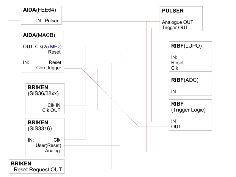
The attached figure shows the configuration used to test the synchronization of the DAQ systems using a
correlation scalar counted from a common clock signal (DAQcorrelation_diagram.pdf).

The chosen solution was to use a 25 MHz clock generated by the MACB modules of AIDA, which was distributed to
the other two systems by a SIS36/38xx module in the BRIKEN VME crate.

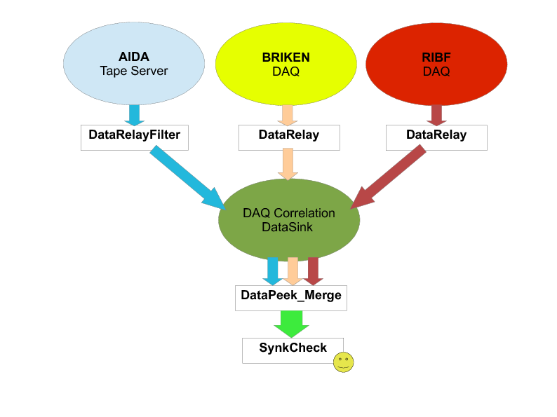
The correlation can be monitored online using the MIDAS DataXfer and DataSpy libraries
(http://npg.dl.ac.uk/MIDAS/DataAcq/Data.html). Each system operates a
DataRelay program that sends a data stream consisting only of IDs and time-stamps to a common DataSink (this
requires a DataRelay code that does some filtering of the raw data for each system). The scheme is shown in
attached diagram (DAQsoftware.pdf).

The DataPeek_Merge and SyncCheck codes use C++11 for parallelization of tasks, which is a helpful feature to
improve the efficiency of finding coincidences between the correlation pulses. Thus, the code will not run in
PCs with any Linux version. For example, it requires version 7 of ScientificLinux, which installed in the PC
being used for BRIKEN DAQ control that will stay at RIBF for the time being.


++ SYNCHRONIZATION RESULTS ++

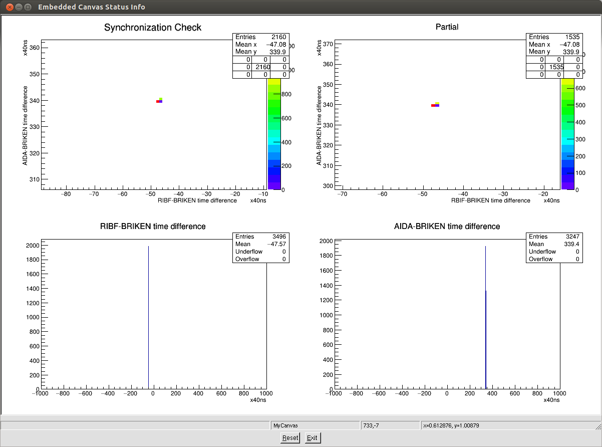
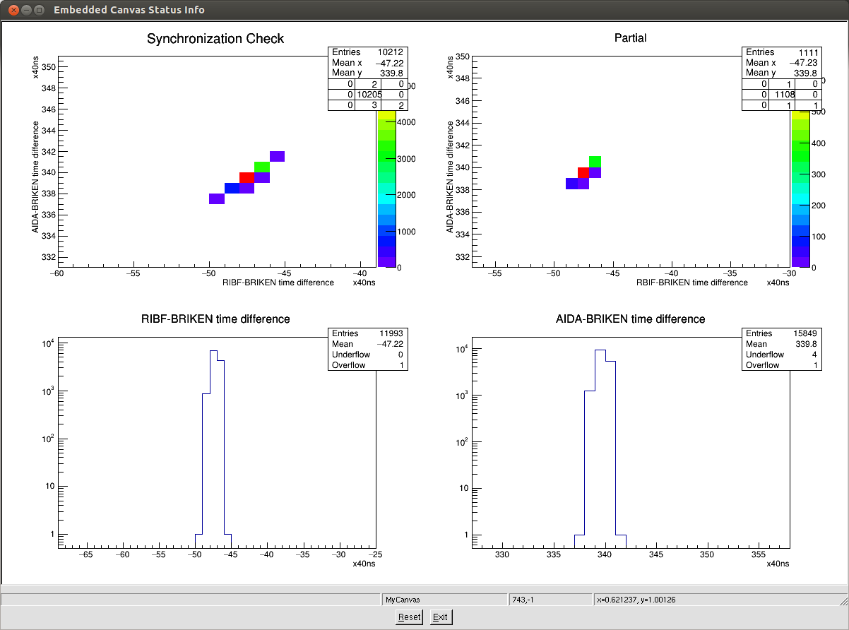
The figure correlation_25Hz.png shows a correlation plot for the BRIKEN+RIBF+AIDA running with correlations done
by a pulser at 25 Hz. A large fraction of the pulsers appear in the double-coincidence plots (top row; same plots,
except the 'Partial' one is automatically cleared every ~10seconds).

The bottom plots show the pair-wise correlations between BRIKEN and RIBF or AIDA. BRIKEN was defined as the
'master' in this test, but current version of the program is flexible to select any stream as the master one.

The second figure (correlation_random.png) shows the same test, but using a non-periodic pulser to trigger the
correlation scalar. We observed the same level of synchronization (peaks look brader just because of the zoom level). |
| Attachment 1: DAQcorrelation_diagram.pdf
|
|
| Attachment 2: DAQsoftware.pdf
|
|
| Attachment 3: correlation_25Hz.png
|
|
| Attachment 4: correlation_random.png
|
|
|
|
280
|
Mon Jun 6 08:57:34 2016 |
GL,PW, YS, TD, ML | AIDA run 1112 - Sync problem |
After starting run 1112, we noticed that the merge program was waiting for a first sync. It then turned out that all syncs had disappeared. This required an entire reboot of the AIDA DAQ. Consequently, AIDA run 1112 should not be used. |
|
|
865
|
Wed Mar 1 16:42:06 2023 |
Further results from Mezzanine bench tests | PJCS |
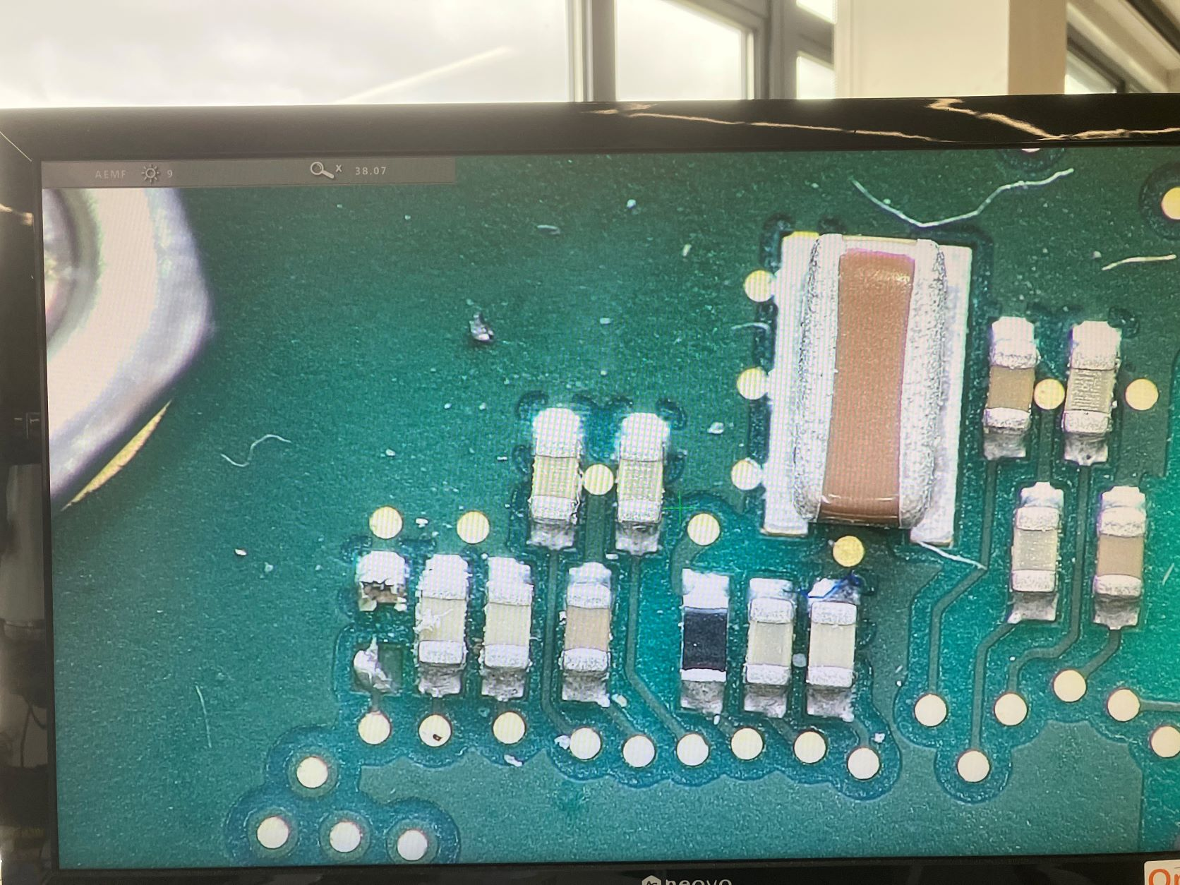
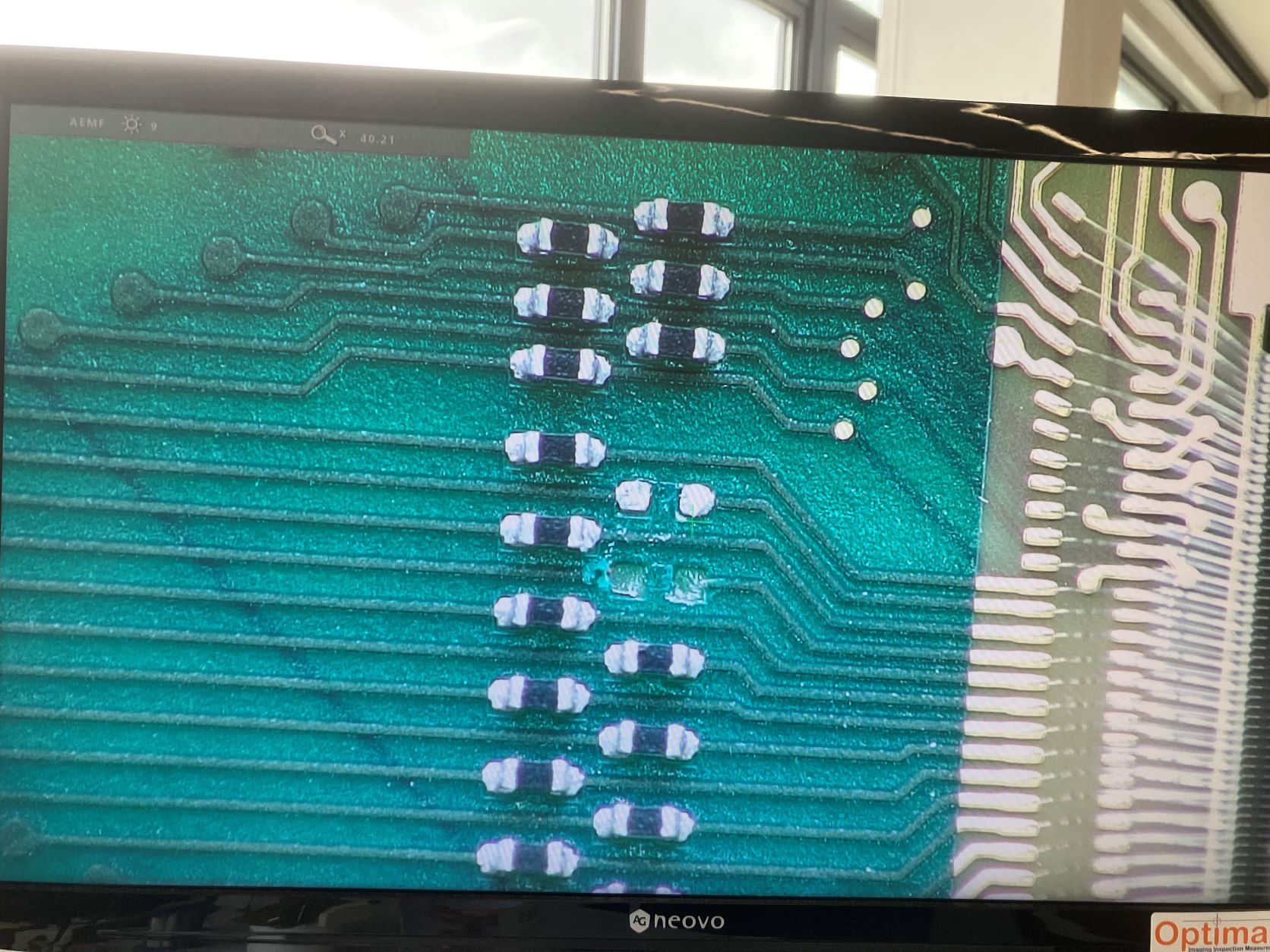
Carried out some further work on failed mezzanine modules.
Inspected them externally and removed the copper block, internally with a bench microscope.
Found two obvious faults ..... broken components with scrambled pcb tracks.
To help determine problems with loading control registers I've added a new menu item in the ASIC control window to allow all four ASIC return values to be checked. This is only useful at the mezzanine test system.
Tested 7 that were labelled as faulty. Failed all of them. 2 with broken components and 1 with some broken bond wires.
Tested one fresh from the cupboard. It failed with over current on the +5v psu ( > 4A! ).
I propose to create a method of testing these mezzanines which allows better access to the power supply regulators ( LT3080 ) and the associated control voltage.
|
| Attachment 1: mezz_cap_gone_resized.jpg
|
|
| Attachment 2: mezz_resistors_resized.jpg
|
|
|
|
536
|
Mon Mar 27 03:28:53 2017 |
DK, TD, JA | Clock settings at the waveform generator stage |
Clock settings for this experiment are slightly different than in the previous case.

Below are strictly the settings for the waveform generator itself.

Sent to AIDA side: 0 to 5 V amplitude, 50 MHz frequency

Sent to BRIKEN side: 0 to 5 V amplitude, 25 MHz frequency

Thus, both teams are taking TTL-type signals.  However, the BRIKEN one goes to the Philips module which essentially converts it straight away to NIM.

There may have been a slight misunderstanding yesterday about the setup, but finally the waveform signal going to BRIKEN was checked and there was no problem.  So we don't make
any changes (e.g. changing the waveform generator to a NIM-type output). |
|
|
432
|
Tue Nov 8 13:06:18 2016 |
DK, TD, CG, OH | NP1412 Run 1 |
AIDA run with Takechi experiment. 71~73 Ni beam setting
F5 carbon target is: IN
F7 CH2 target is: OUT
F11 carbon target is: OUT
All variable Al degraders at F11 are OUT
When the run started, we had 1mm Al degrader in (count rate of AIDA was near the background rate)
Then we took out the final 1mm Al degrader, and we started to get counts on AIDA (600 Hz on detectors 1, 2, 3, very little on 4, 5, 6)
Run file: NP1412/R1
ASIC parameter file: 2016Nov07-23.03.06
5 mm thick Al stopper is at the center of BRIKEN, with AIDA slightly behind it
Run start: 8/11/2016 22:00
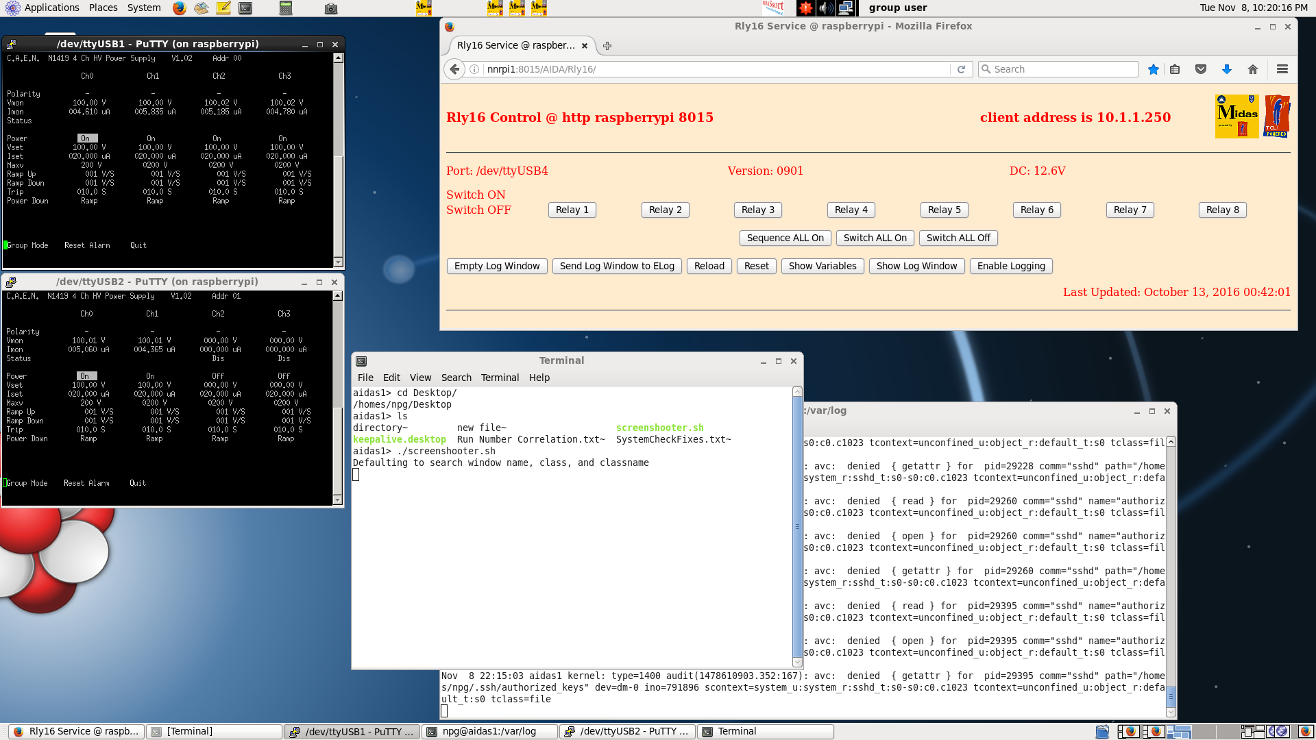
Leak currents (4 to 5 uA each) shown as Attachment #1
22:30 All degraders removed at end of run Run Stop time 22:30 |
| Attachment 1: 14_JST_2016.png
|
|
|
|
310
|
Sat Jun 11 17:24:11 2016 |
DK, TD | Sunday 12 June 2016 |
Runs 41 and 42 are quite short. Run 41 was interrupted by the beam dropping (operators called), and run 42 we are just trying to get EURICA to synchronize with AIDA DAQ.
1:08 Started AIDA Run 43 for 60Ti beam (EURICA run 2027; BigRIPS run 2132; CAEN Run 3018)
Leak currents less than 5 uA. See attachments 1 & 2
Scalers are shown as attachment 3
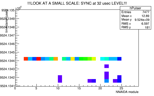
FEEE synchronization with pulser signal is shown as attachment 4
1:21 operator calls to note that the beam is stopped.
1:25 started AIDA run 44 for 60Ti beam (EURICA run 2028; BigRIPS #2133; CAEN #3019)
1:31 stopped because CAEN DAQ goes down.
1:34 started AIDA run 45 for 60Ti beam (EURICA run 2029; BigRIPS #2134; CAEN #3020)
1:37 data stops writing to disk for AIDA for unknown reason.
1:50 nnaida11 showed no SYNCs. Stop / GO on Run Control resolves it.
but 18 is off for the merger link. was this the status quo? try to reboot the merger but everything gets upset.
my first power cycle alone! (daid)
load the settings file 2016Jun10-20.30.18 which seems to be the most recent one
it takes some time, but finally I can get things up and running it seems.
2:40 still 18 link is down. strange. hopefully it's an acceptable loss, because I think it has been a long day for everyone.
OH DUH! nnaida19 hasn't been working for the entire experiment!! Just I forgot on the merge links it is offset 0 and not offset 1 for counting.
I could get some practice restoring AIDA at least?
Anyway, there had been some problems from run 45, and now all is well.
2:40 AIDA run 46. It's just a test that the system is working. But I forgot to put the TapeServer Volume Name so who knows where it ended up (discarded to /dev/null ?)
2:42 AIDA run 47, started with EURICA up and ready. (BigRIPS #2137; EUIRCA #2032; CAEN #3023)
Basically everything looks reasonable I think
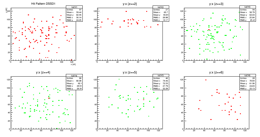
SSD XY pattern looks basically okay. See attachment
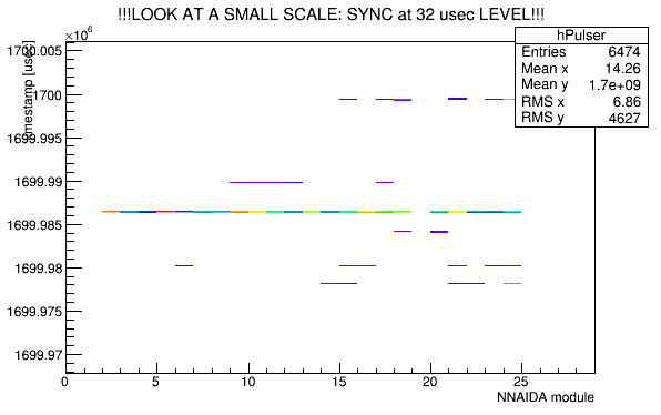
Pulser shows the FEEs are synchronized nicely. See attachment 6
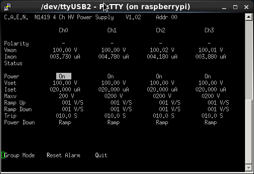
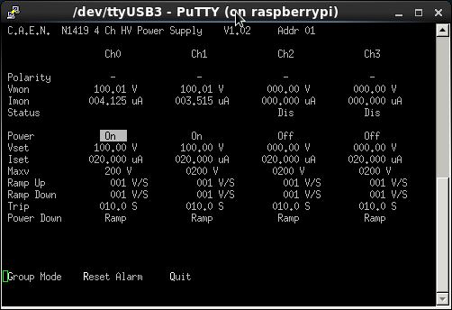
Biases and leak currents are shown in attachments 7 and 8
Scalers are shown as attachment 9
Check the pause/resumes. From the html Statistics page, nnaida20 shows some pauses, while nnaida24 seems to pause regularly.
I use Tom's program as outlined in a previous elog. He said we shall want the elapsed dead time to be much less than the timestamp elapsed
~/td/GREAT/analyser2 /TapeData/NP1512/AIDA47_26
*** GREAT format 3.2.0 analyser - TD - May 2014
*** FEE64 discriminator: block: 23312 ptr: 2071 data: 0x98638000 module: 24 information type: 6 information field: 0x00038000 ts: 0x0083500000A0 OLD: ts: 0x00836000009F tag: 2 type: 6
*** ERROR: READ I/O error: 5002
blocks: 32000
ADC data format: 140888182 ( 963280.2 Hz)
Other data format: 120231818 ( 822048.6 Hz)
Sample trace data format: 0 ( 0.0 Hz)
Undefined format: 0 ( 0.0 Hz)
Other data format type: PAUSE: 4747 ( 32.5 Hz)
RESUME: 4747 ( 32.5 Hz)
SYNC100: 55794 ( 381.5 Hz)
FEE64 disc: 119436810 ( 816612.9 Hz)
MBS info: 729720 ( 4989.2 Hz)
Other info: 0 ( 0.0 Hz)
ADC data range bit set: 286072 ( 1955.9 Hz)
Timewarps: ADC: 0 ( 0.0 Hz)
PAUSE: 0 ( 0.0 Hz)
RESUME: 0 ( 0.0 Hz)
SYNC100: 1 ( 0.0 Hz)
FEE64 disc: 1 ( 0.0 Hz)
MBS info: 0 ( 0.0 Hz)
Undefined: 0 ( 0.0 Hz)
Sample trace: 0 ( 0.0 Hz)
Timestamp elapsed time: 146.259 s
FEE module #: 1 elapsed dead time 0.019 s
FEE module #: 2 elapsed dead time 0.232 s
FEE module #: 3 elapsed dead time 0.002 s
FEE module #: 4 elapsed dead time 0.000 s
FEE module #: 5 elapsed dead time 0.255 s
FEE module #: 6 elapsed dead time 0.215 s
FEE module #: 7 elapsed dead time 0.001 s
FEE module #: 8 elapsed dead time 0.000 s
FEE module #: 9 elapsed dead time 0.028 s
FEE module #: 10 elapsed dead time 0.000 s
FEE module #: 11 elapsed dead time 0.036 s
FEE module #: 12 elapsed dead time 0.089 s
FEE module #: 13 elapsed dead time 0.001 s
FEE module #: 14 elapsed dead time 0.034 s
FEE module #: 15 elapsed dead time 0.000 s
FEE module #: 16 elapsed dead time 0.478 s
FEE module #: 17 elapsed dead time 0.000 s
FEE module #: 18 elapsed dead time 0.077 s
FEE module #: 19 elapsed dead time 0.000 s
FEE module #: 20 elapsed dead time 0.166 s
FEE module #: 21 elapsed dead time 0.760 s
FEE module #: 22 elapsed dead time 0.029 s
FEE module #: 23 elapsed dead time 0.755 s
FEE module #: 24 elapsed dead time 0.448 s
FEE module #: 25 elapsed dead time 0.000 s
FEE module #: 26 elapsed dead time 0.000 s
FEE module #: 27 elapsed dead time 0.000 s
FEE module #: 28 elapsed dead time 0.000 s
FEE module #: 29 elapsed dead time 0.000 s
FEE module #: 30 elapsed dead time 0.000 s
FEE module #: 31 elapsed dead time 0.000 s
FEE module #: 32 elapsed dead time 0.000 s
It could be around 5% total, but I do not think it is so terrible.
4:56 AIDA Run 47_53 begins 4:56. We do not restart the runs. EURICA also automatically had the new run 2033 at 4:56. BigRIPS manually stop / start is now at 2138 (4:57). CAEN run is still 3023.
5:02: At start of run, the beam dropped
5:05 PPAC F3 1A trips.
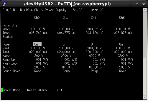
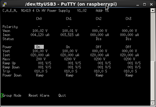
Leak current shown as attachment 10 and 11
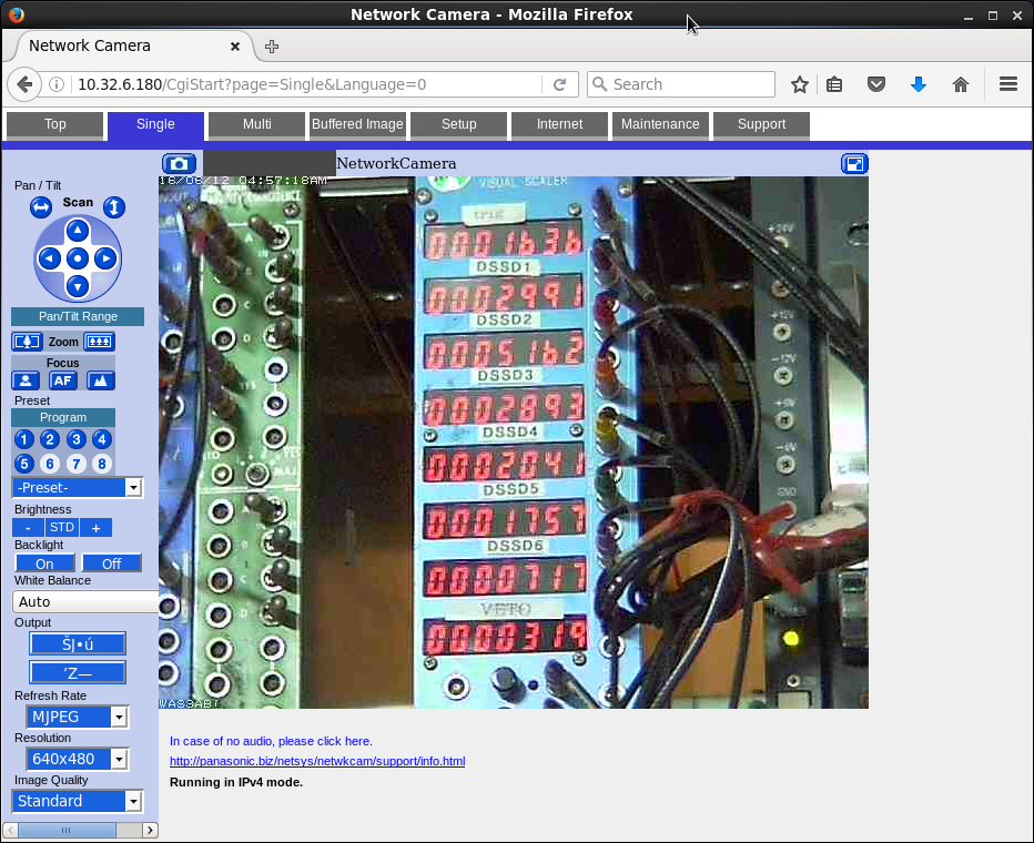
Scalers shown as attachment 12
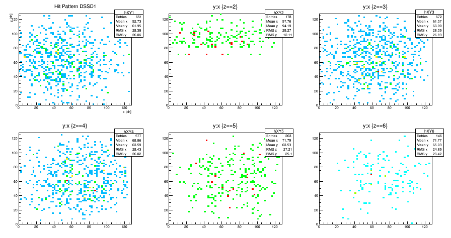
FEE sync looks good, as well as SSD XY. About 370 MB of ROOT tree (compared to typical check of 50 MB) Attachments 13 and 14, respectively.
Here are Tom's pause information
aidas1> ~/td/GREAT/analyser2 /TapeData/NP1512/AIDA47_53
*** GREAT format 3.2.0 analyser - TD - May 2014
*** ERROR: READ I/O error: 5002
blocks: 32000
ADC data format: 146454667 ( 944617.0 Hz)
Other data format: 114665333 ( 739579.2 Hz)
Sample trace data format: 0 ( 0.0 Hz)
Undefined format: 0 ( 0.0 Hz)
Other data format type: PAUSE: 4216 ( 27.2 Hz)
RESUME: 4216 ( 27.2 Hz)
SYNC100: 59144 ( 381.5 Hz)
FEE64 disc: 113857390 ( 734368.1 Hz)
MBS info: 740367 ( 4775.3 Hz)
Other info: 0 ( 0.0 Hz)
ADC data range bit set: 272434 ( 1757.2 Hz)
Timewarps: ADC: 0 ( 0.0 Hz)
PAUSE: 1 ( 0.0 Hz)
RESUME: 0 ( 0.0 Hz)
SYNC100: 0 ( 0.0 Hz)
FEE64 disc: 0 ( 0.0 Hz)
MBS info: 0 ( 0.0 Hz)
Undefined: 0 ( 0.0 Hz)
Sample trace: 0 ( 0.0 Hz)
Timestamp elapsed time: 155.041 s
FEE module #: 1 elapsed dead time 0.014 s
FEE module #: 2 elapsed dead time 0.231 s
FEE module #: 3 elapsed dead time 0.005 s
FEE module #: 4 elapsed dead time 0.000 s
FEE module #: 5 elapsed dead time 0.220 s
FEE module #: 6 elapsed dead time 0.040 s
FEE module #: 7 elapsed dead time 0.000 s
FEE module #: 8 elapsed dead time 0.009 s
FEE module #: 9 elapsed dead time 0.043 s
FEE module #: 10 elapsed dead time 0.005 s
FEE module #: 11 elapsed dead time 0.064 s
FEE module #: 12 elapsed dead time 0.006 s
FEE module #: 13 elapsed dead time 0.008 s
FEE module #: 14 elapsed dead time 0.039 s
FEE module #: 15 elapsed dead time 0.065 s
FEE module #: 16 elapsed dead time 0.457 s
FEE module #: 17 elapsed dead time 0.000 s
FEE module #: 18 elapsed dead time 0.015 s
FEE module #: 19 elapsed dead time 0.000 s
FEE module #: 20 elapsed dead time 0.059 s
FEE module #: 21 elapsed dead time 0.330 s
FEE module #: 22 elapsed dead time 0.043 s
FEE module #: 23 elapsed dead time 0.989 s
FEE module #: 24 elapsed dead time 0.462 s
FEE module #: 25 elapsed dead time 0.000 s
FEE module #: 26 elapsed dead time 0.000 s
FEE module #: 27 elapsed dead time 0.000 s
FEE module #: 28 elapsed dead time 0.000 s
FEE module #: 29 elapsed dead time 0.000 s
FEE module #: 30 elapsed dead time 0.000 s
FEE module #: 31 elapsed dead time 0.000 s
FEE module #: 32 elapsed dead time 0.000 s
*** Program elapsed time: 21.295s ( 1502.706 blocks/s, 93.919 Mb/s)
|
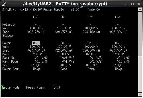
| Attachment 1: bias1_AIDA43_1206-0109.png
|
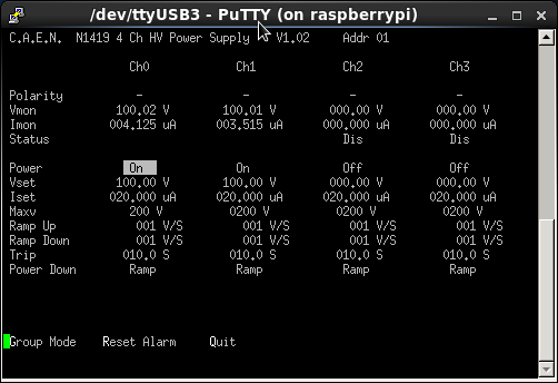
|
| Attachment 2: bias2_AIDA43_1206-01.17.png
|
|
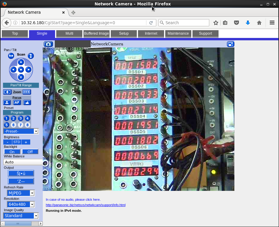
| Attachment 3: Scalers_AIDA43_1206-0110.png
|
|
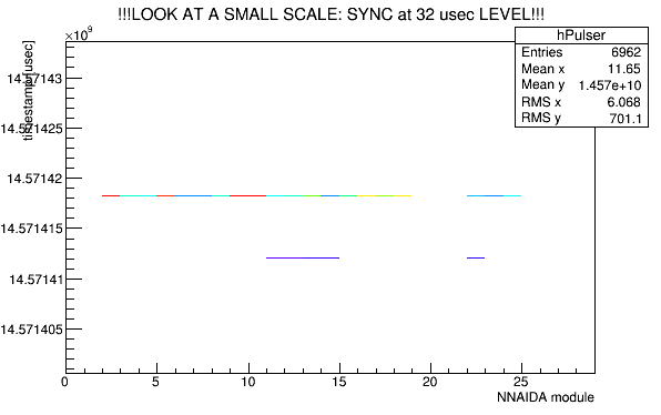
| Attachment 4: FEEE-Pulser_AIDA43_1206-01.13.png
|
|
| Attachment 5: SSD-XY_AIDA47_1206_02.53.png
|
|
| Attachment 6: FEEE-Pulser_AIDA47_1206-02.56.png
|
|
| Attachment 7: bias1_AIDA47_1206-02.59.png
|
|
| Attachment 8: bias2_AIDA47_1206-03.00.png
|
|
| Attachment 9: Scalers_AIDA47_1206-03.00.png
|
|
| Attachment 10: bias1_AIDA47_53_1206-05.01.png
|
|
| Attachment 11: bias2_AIDA47_53_1206-05.01.png
|
|
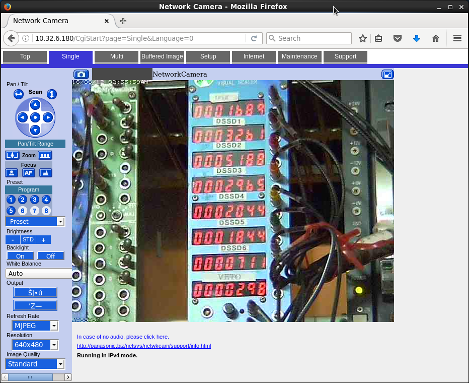
| Attachment 12: Scalers_AIDA47_53_1206-05.01.png
|
|
| Attachment 13: FEEE-Pulser_AIDA47_53_1206-02.56.png
|
|
| Attachment 14: SSD-XY_AIDA47_53_1206_02.53.png
|
|
|
|
440
|
Tue Nov 8 23:16:15 2016 |
DK, TD | NP1412 R11 |
Recovered AIDA after power cycle (unknown cause of crash from the end of R10)
Corresponding run in BRIKEN: 161109_0814_747576Ni_012
Run condition for Takechi has changed since our crash
F5 empty; F7 CH2; F11 carbon
At the beginning of our run, we had all Aluminium degraders in (1 mm was added back after our crash for safety)
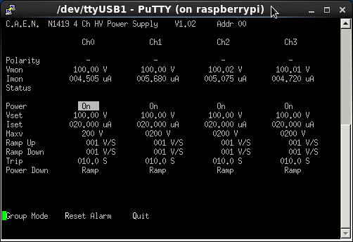
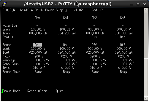
We finally removed all but 1 mm Al on the variable degrader
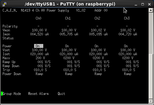
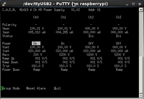
SSD biases shown as attachments 1 and 2
8:20 They inform us that they want to take the F11 carbon out (in the middle of elog entry) |
| Attachment 1: R11_USB1.png
|
|
| Attachment 2: R11_USB2.png
|
|
|
|
441
|
Tue Nov 8 23:36:56 2016 |
DK, TD | NP1412 R12 |
Takechi team changes the condition: F5 carbon; F7 empty; F11 carbon
F11 Plastic is 1.1kHz
BRIKEN: 161109_0828_747576Ni_013.dlt
AIDA settings file: 2016Nov07-23.03.06
Initially we have all the Al variable degraders in, but then after the run began and we saw nothing, we reduce it to 1 mm of Aluminium.
Biases shown as attachments 1 and 2
Offline data rates (from R12_2)
*** DSSSD # 1 count: 1022 old count: 709 dt: 2.91 s HEC rate: 351.69 Hz
*** DSSSD # 2 count: 863 old count: 597 dt: 2.91 s HEC rate: 296.98 Hz
*** DSSSD # 3 count: 995 old count: 693 dt: 2.91 s HEC rate: 342.40 Hz
*** DSSSD # 4 count: 827 old count: 575 dt: 2.91 s HEC rate: 284.59 Hz
*** DSSSD # 5 count: 246 old count: 164 dt: 2.91 s HEC rate: 84.65 Hz
*** DSSSD # 6 count: 11 old count: 10 dt: 2.91 s HEC rate: 3.79 Hz
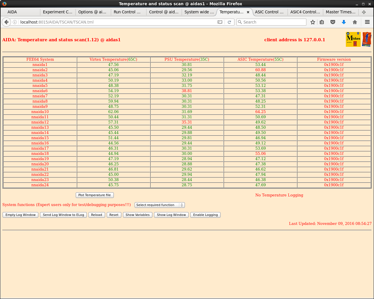
FEE64 temperatures OK - see attachment 3
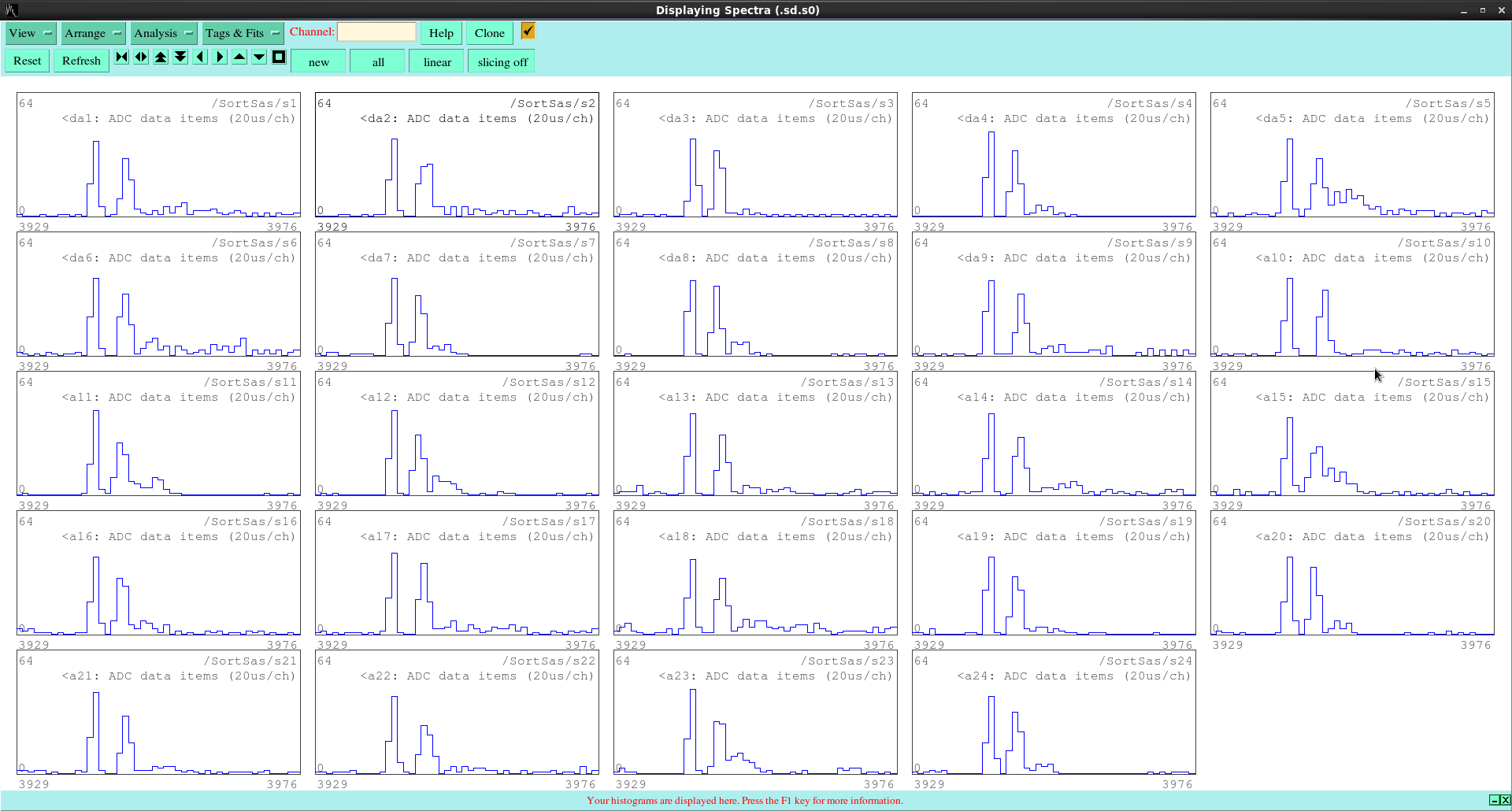
08.55 Online analysis shows ADC data synchronised - see attachment 4
09.05 Rate, HitRate, 1.8.L and 1.8.H energy spectra - see attachmemnts 5-10
Run stop 9:46
|
| Attachment 1: R12_USB1.png
|
|
| Attachment 2: R12_USB2.png
|
|
| Attachment 3: 49.png
|
|
| Attachment 4: 50.png
|
|
| Attachment 5: 1.png
|

|
| Attachment 6: 2.png
|

|
| Attachment 7: 3.png
|

|
| Attachment 8: 4.png
|

|
| Attachment 9: 5.png
|

|
| Attachment 10: 6.png
|

|
|
|
470
|
Sat Nov 26 06:57:36 2016 |
DK, TD | Offline analysis of R7_37 |
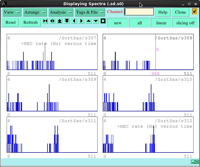
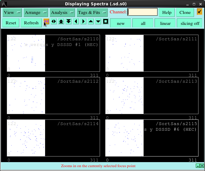
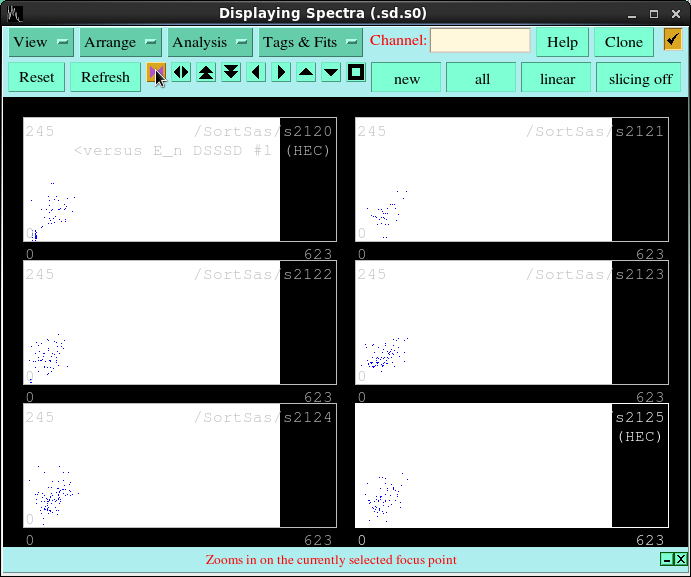
R7_37 3mm Pb + from 0 to 1.8mm W (+ up to 3mm Al, 1mm per W layer - 0.3mm W, 0.5mm W & 1.0 W))

S O R T    C O M P L E T E ..... Sat Nov 26 15:53:38 2016


 *** ENTRY finish

 *** data items:  261088000 ( 109032.27 Hz)
 *** ADC events:   35610281 (  14871.12 Hz)
 *** time warps:          0 (      0.00 Hz)
 *** DSSSD # 1 count:   5687384 old count:   5685468 dt:    296.31 s  LEC rate:  19194.17 Hz
 *** DSSSD # 2 count:   5434012 old count:   5432199 dt:    296.31 s  LEC rate:  18339.08 Hz
 *** DSSSD # 3 count:   2817667 old count:   2816768 dt:    296.31 s  LEC rate:   9509.26 Hz
 *** DSSSD # 4 count:   2408578 old count:   2407807 dt:    296.31 s  LEC rate:   8128.63 Hz
 *** DSSSD # 5 count:   1752915 old count:   1752351 dt:    296.31 s  LEC rate:   5915.86 Hz
 *** DSSSD # 6 count:   3659110 old count:   3657789 dt:    296.31 s  LEC rate:  12349.01 Hz
 *** DSSSD # 1 count:        47 old count:        47 dt:    296.31 s  HEC rate:      0.16 Hz
 *** DSSSD # 2 count:        33 old count:        33 dt:    296.31 s  HEC rate:      0.11 Hz
 *** DSSSD # 3 count:        47 old count:        47 dt:    296.31 s  HEC rate:      0.16 Hz
 *** DSSSD # 4 count:        70 old count:        70 dt:    296.31 s  HEC rate:      0.24 Hz
 *** DSSSD # 5 count:        83 old count:        83 dt:    296.31 s  HEC rate:      0.28 Hz
 *** DSSSD # 6 count:        55 old count:        55 dt:    296.31 s  HEC rate:      0.19 Hz

 *** ENTRY finish ends

S O R T S T O P P E D ..... Sat Nov 26 15: |
| Attachment 1: 100.png
|
|
| Attachment 2: 101.png
|
|
| Attachment 3: 102.png
|
|
| Attachment 4: K3MVQY.tmp
|
|
|
542
|
Wed Mar 29 08:13:34 2017 |
DK, PV, JL, CG | Degrader, Pb wall opening |
16:21

Chris noticed that when the degraders that are at the beam right position when they are "out" may not be fully removed from the beamline.  It's difficult to make a good
measurement, but it looks like several cm (~3 cm?).

The degrader that moves out to the beam left side has its inner-most edge roughly flush with the square opening of the polyethylene wall.

It does not seem that the issue is about the slider's center position.  This we checked yesterday and within the judgement of our eyes and limited viewing angle, several people
independently confirmed that the center of the degrader slider is near the true center of BRIKEN and AIDA with respect to the beam axis.  It appears to be an issue of the
slider's total track length.  Also it should be noted that the degraders are installed in a somewhat asymmetric way, so the consideration of one opening side of the degraders
when fully open and another isn't fully out may not be germane.

16:44

We shifted the center of the degrader slider to be about less 1 cm to the beam right.  So now the degraders a bit more symmetric as far as their inner edges are related to the
opening in the polyethylene wall.

As for the Pb wall, its opening is ~10.5 cm.  The "window" in the Pb wall is slightly shifted to the beam left side.  The left side is ~5.5 cm from the center, where as the right
side is <5.5 cm from the center. |
|
|
324
|
Tue Jul 5 13:43:02 2016 |
DK, PV | Pulser Test Run after AIDA is moved |
Needed to run startx and start the TcLHttpd server on rpi
Following along here: https://elog.ph.ed.ac.uk/AIDA/242
Can now access http://nnrpi1:8015/AIDA/Rly16/
Window at first connection reads:
Using /dev/ttyUSB0 firmware version 0
Using /dev/ttyUSB1 firmware version 0901
Looks good. Sequence ALL On was selected
(By mistake, I then clicked Relay # to turn off...misread instructions...Switch all OFF, then sequence ALL on again)
7:51 they are turned on. Waiting several minutes now.
Add 4 L of water to the chiller
8:12
Save/Control Settings from Hardware Control tab:
Selected: 2016Jun13-00.53.55 and Restore. (missing from elog 242)
From Run Control, Enable Histogramming, Data Transfer: Enable #1 All (missing from elog 242)
TapeServer / Merger / Httpd started on Workspace 2
TapeServer reports
Cannot issue more Access Tokens: Claim TapeServer returned:- 3 Capability table is full
Make a new directory for storing test data: /data10/TapeData/July2016
Merger: Setup and configure
Data Statistics shows about ~5 x 10^5 events in many nnaida. Should we use a different setting file?
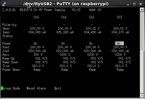
Now we try 2016Jun12-10.10.08
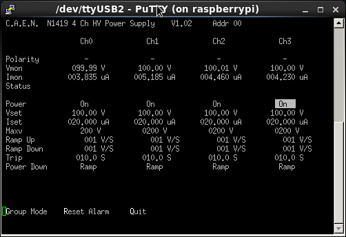
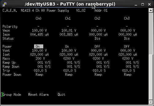
Perform ReSync
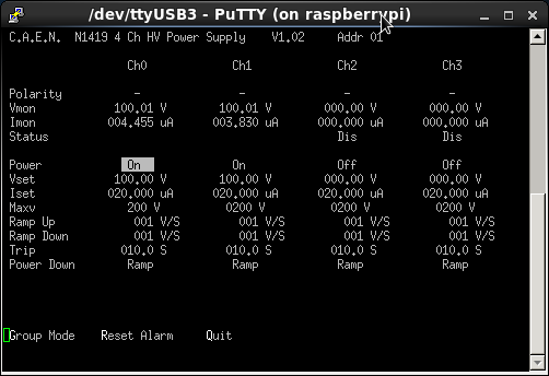
Probably event rate can be high because the SSD bias is off? We set up Putty and turn on all biases to -100 V.
Attachments 1 and 2 show the bias settings after they are turned on.
Good Events rate improves, factor 2 to 4 (now about 100k roughly)
Pulser settings: around ~900 on dial, attenuator x10, x10, x2 switches down, 5x up. Frequency ~250 Hz
21:19
Now we change the Control ASICs (select act on all ASICs, act on all FEEs)
Slow Comparator from 0x8 to 0x20
LEC/MEC Fast Comparator 0x4 to 0x80
Now the Good Events go down to about 10k to 25k roughly
TapeServer starts a run.
Merger started / paused / unpaused
Merger rate is 500k / sec. TapeServer is 4 k / sec.
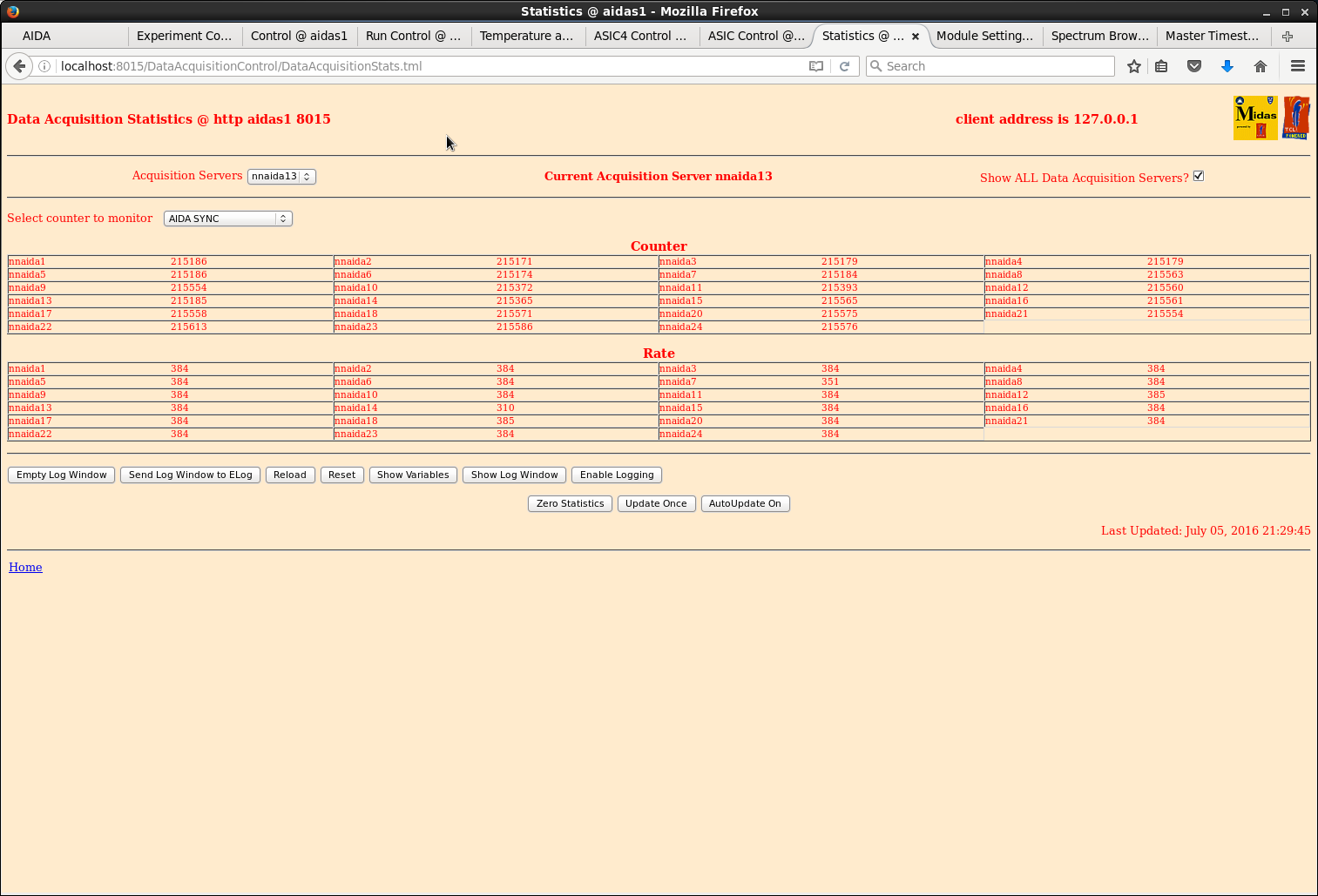
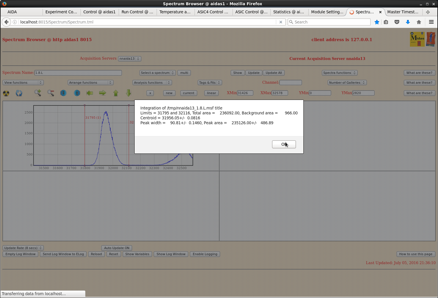
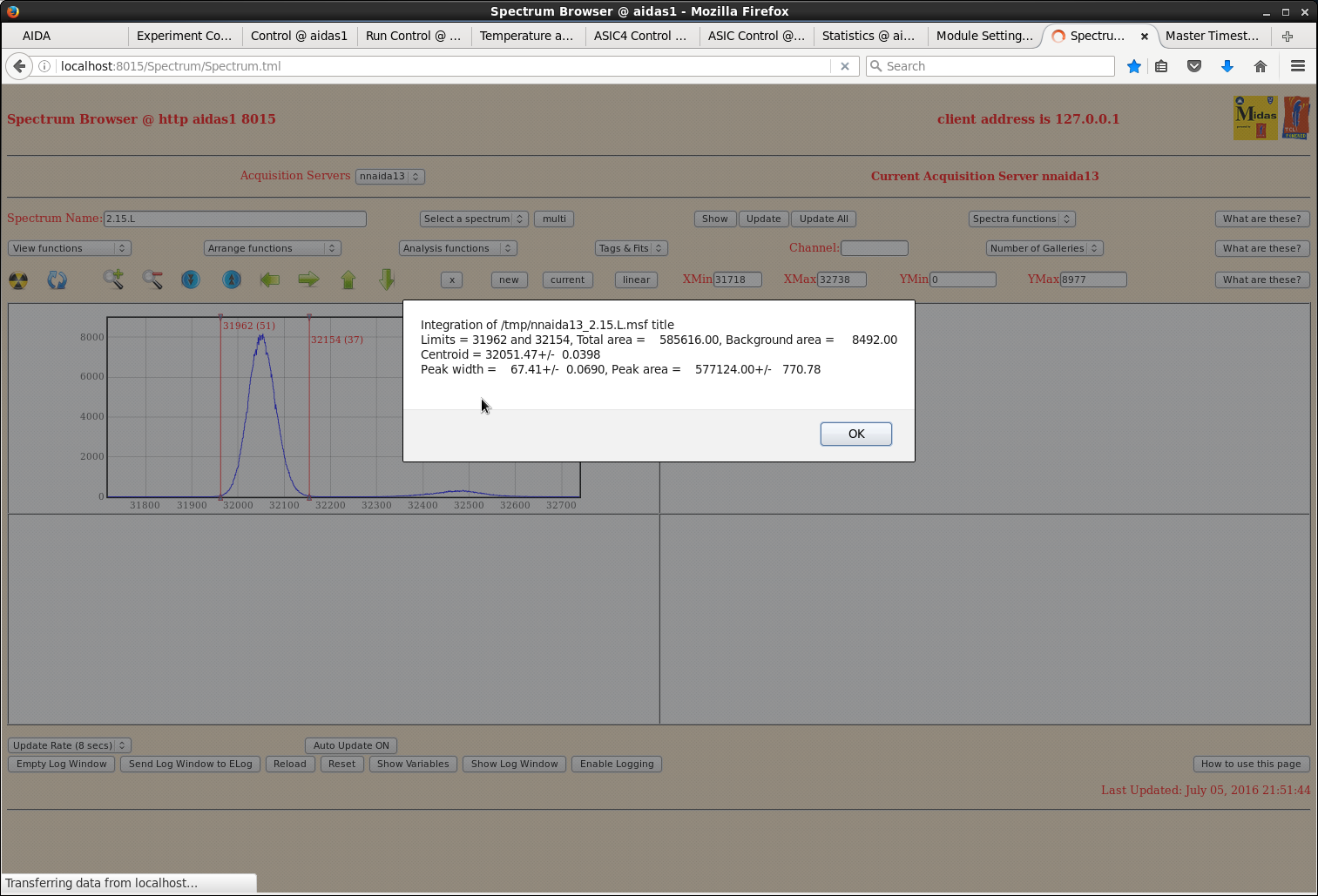
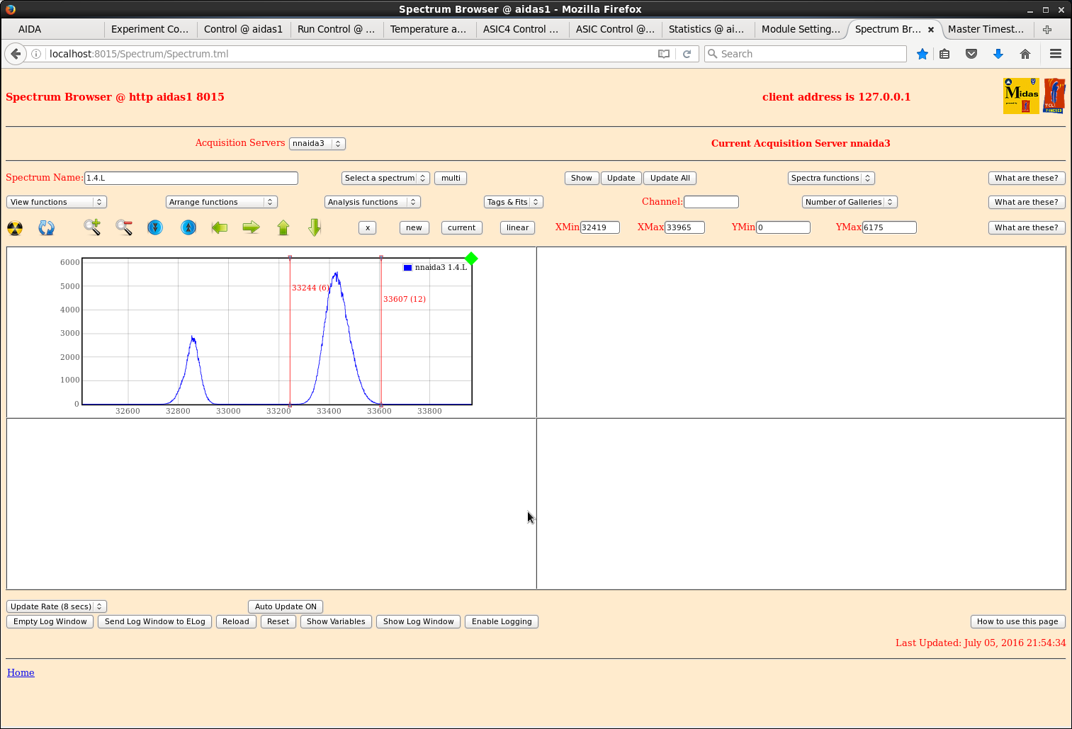
AIDA Syncs shown in Attachment 3
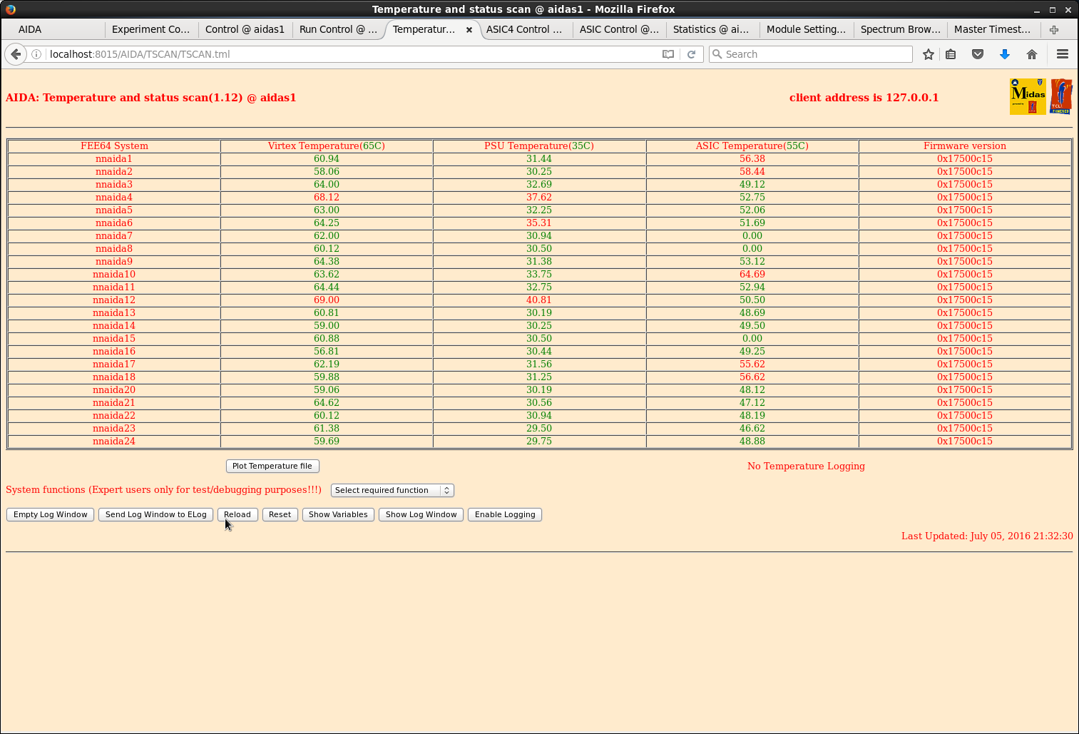
Temps in Attachment 4
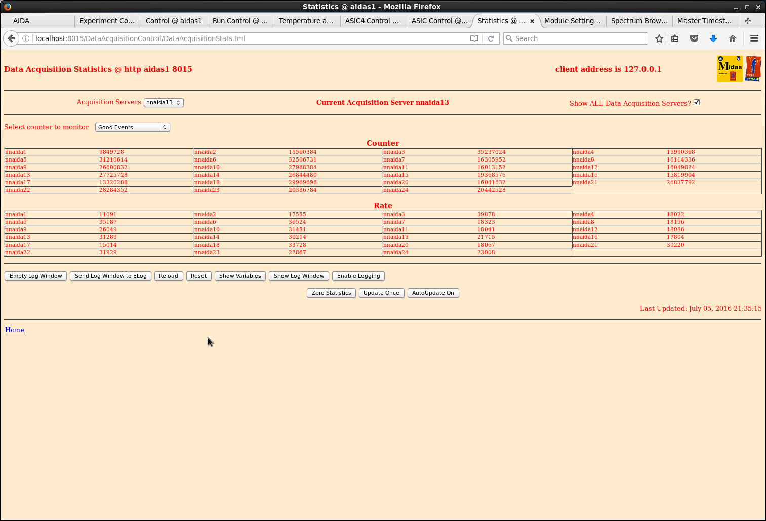
Good Events Attachment 5
Run Number 1
Setting file: 2016Jul05-21.37.20 (Note: I wrote the wrong setting file name last night...this is the right one!)
Show sample pulser peak in Attachment 6, 7, 8
July 6 - 12:29: Stop the run. 114 run files, 2.0 GB each.
Attachments 9, 10 show biases at the end of the run |
| Attachment 1: bias1-2016-07-05_21.12.png
|
|
| Attachment 2: bias2_2016-07-05_21.12.png
|
|
| Attachment 3: aida_sync.png
|
|
| Attachment 4: temps.png
|
|
| Attachment 5: good_evt.png
|
|
| Attachment 6: pulser_peak.png
|
|
| Attachment 7: pulse_2.15_nnaida13.png
|
|
| Attachment 8: pulser-nnaida3.png
|
|
| Attachment 9: bias1_run1_finish.png
|
|
| Attachment 10: bias2_run1_finish.png
|
|