| ID |
Date |
Author |
Subject |
|
372
|
Wed Aug 10 10:30:04 2022 |
TD, JM | Wednesday 10 August |
09.45 Found CARME electrical power off

      Reset power switch of distribution box to on
      Reset fuse of 19" rack extender board

      One of the SIP power modules may be faulty - others switch on OK


14.00 Checked coolant water flow OK

      Transferred Netgear 24 port Gbit switch from AIDA (S4) to CARME (YR09)

      Re-connected FEE64 RJ45 network cables
      Re-connected nnrpi1 RJ45 network cable
      Re-connected RJ45 network cable (yellow) to bottom left connector of YR09 patch panel

      @CRYRING user control rooms

      Connected RJ45 netwwork cable (yellow) from bottom left connector of patch panel (labelled "1-2->YR10" and "3-4->YR10") to CARME server carme-gsi p4p1 port


Retarted HttpdTcl servers on nnrpi1 and carme-gsi.

Normal 5x FEE64 power up

All system wide checks OK

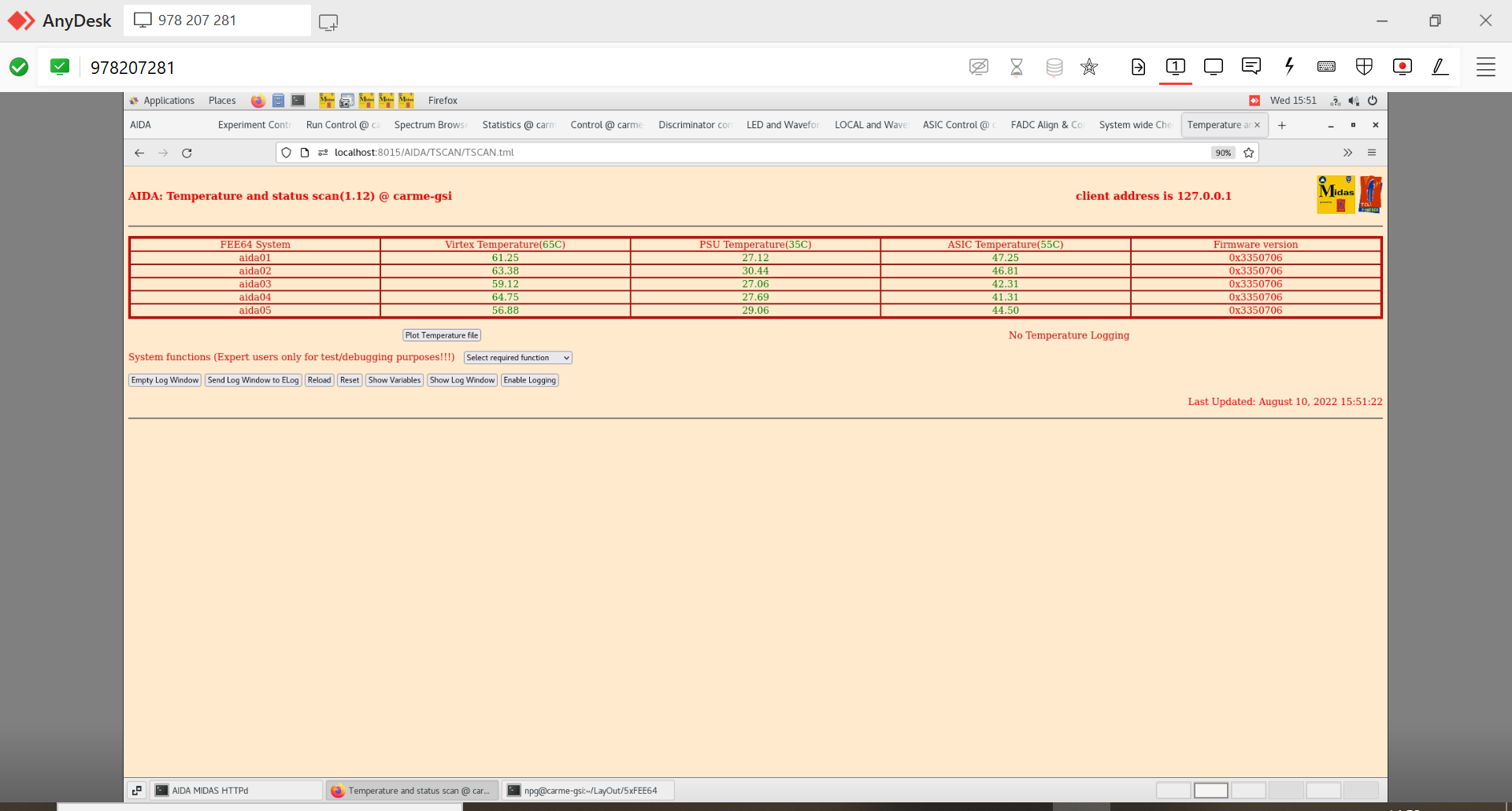
FEE64 temperatures OK - attachment 1

ASIC settings
 slow comparator 0x64

Pulser running through aida01-05
Detectors not biased -> lot of noise aida01-04

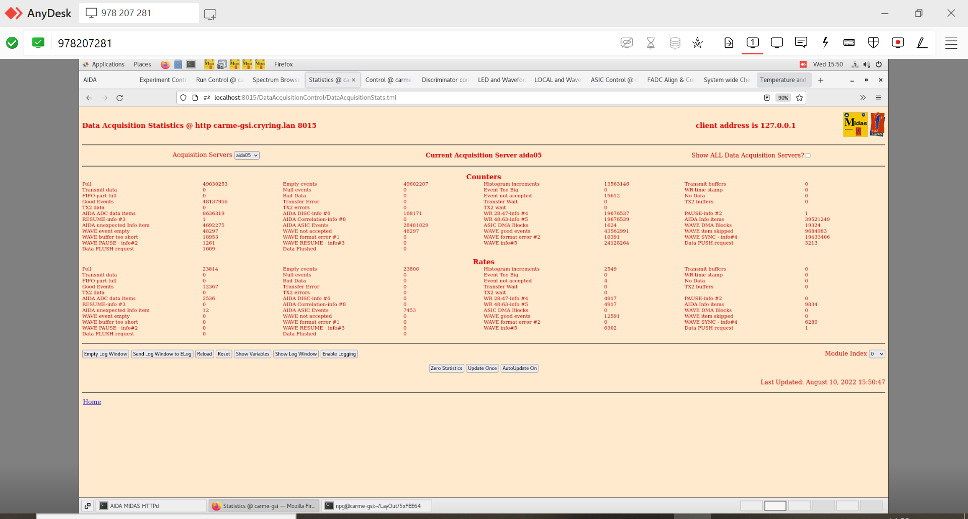
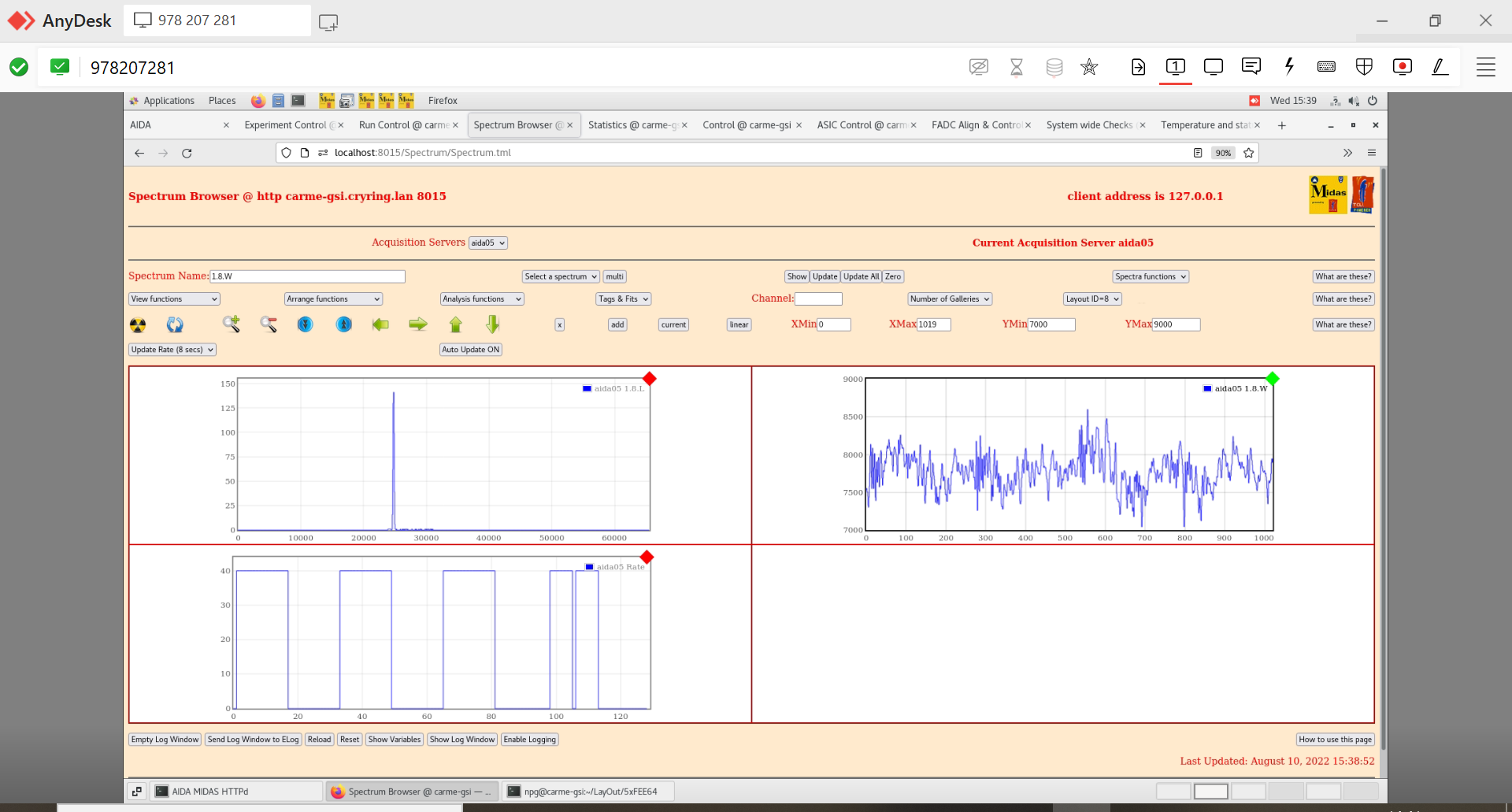
AIDA stats - attachments 3 & 4

aida05 pulser width ~150 channels FWHM, normal settings, shaping time 8us - attachment 4

See attachments 2-4

Tried changing ADC control register to 0xf in local controls tab -> stops waveform producing data -> no effect on pulser width (slight increase to 160 chn)
fast comparator blanked off (enable disable mask in discriminator control) -> no effect on pulser width
aida05 was ungrounded -> grounded aida05 to the same ground as aida01-04 -> pulser width reduced to 46 chns
Set ADC control register back to 0x0 -> waveforms back -> pulser width reduced to 24 chns
Changed shaping time from 8ms to 1ms -> pulser width increased to 67 chns -> changed back to 8ms shaping time -> returns to 24 chn width
Changed shaping time from 8ms to 2ms -> pulser width increased to 52 chns
Changed shaping time from 2ms to 4ms -> pulser width decreased to 33 chns |
| Attachment 1: 4.PNG
|
|
| Attachment 2: 3.PNG
|
|
| Attachment 3: 2.png
|

|
| Attachment 4: 1.png
|
|
|
539
|
Wed Feb 21 07:38:32 2024 |
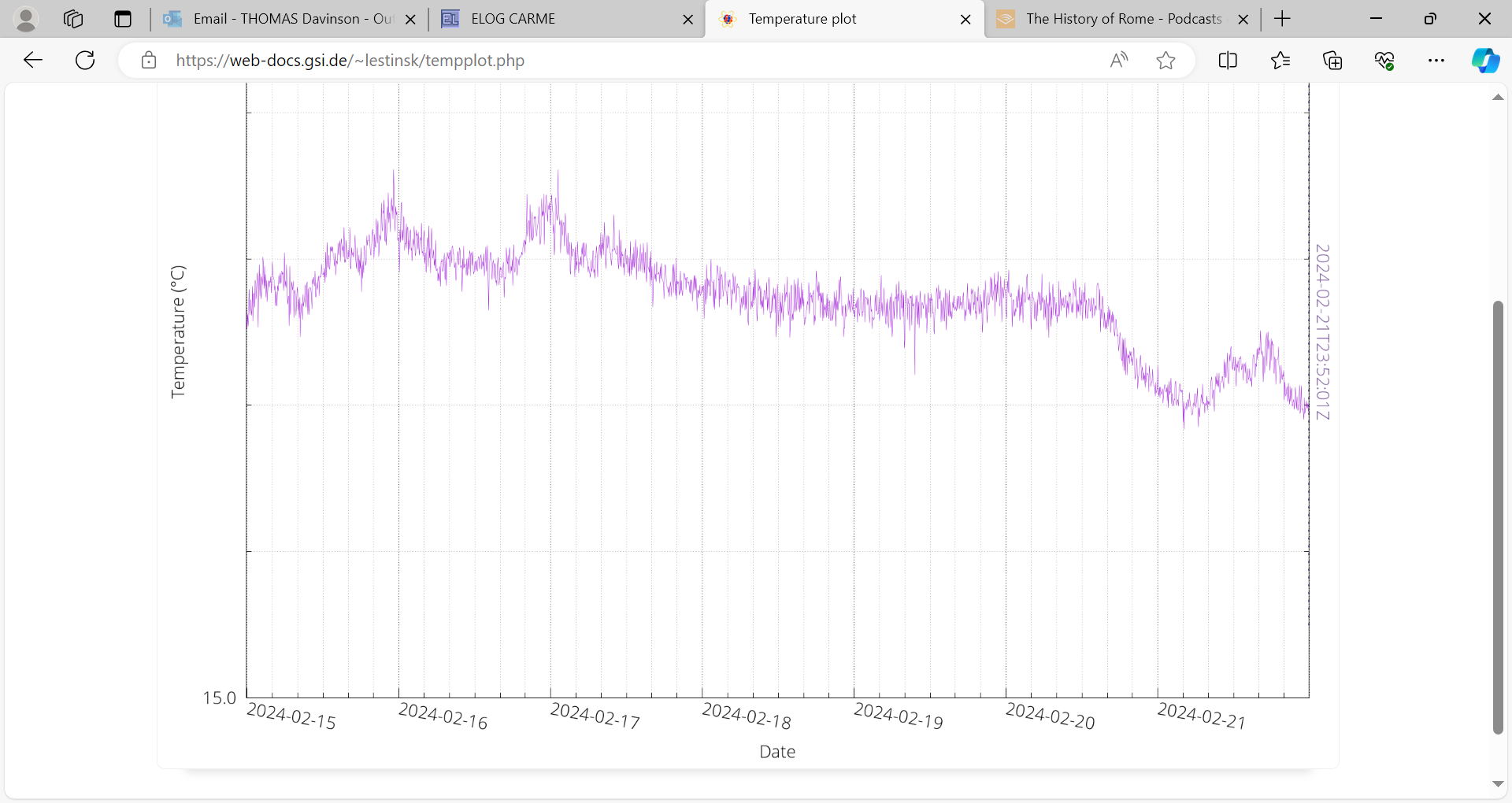
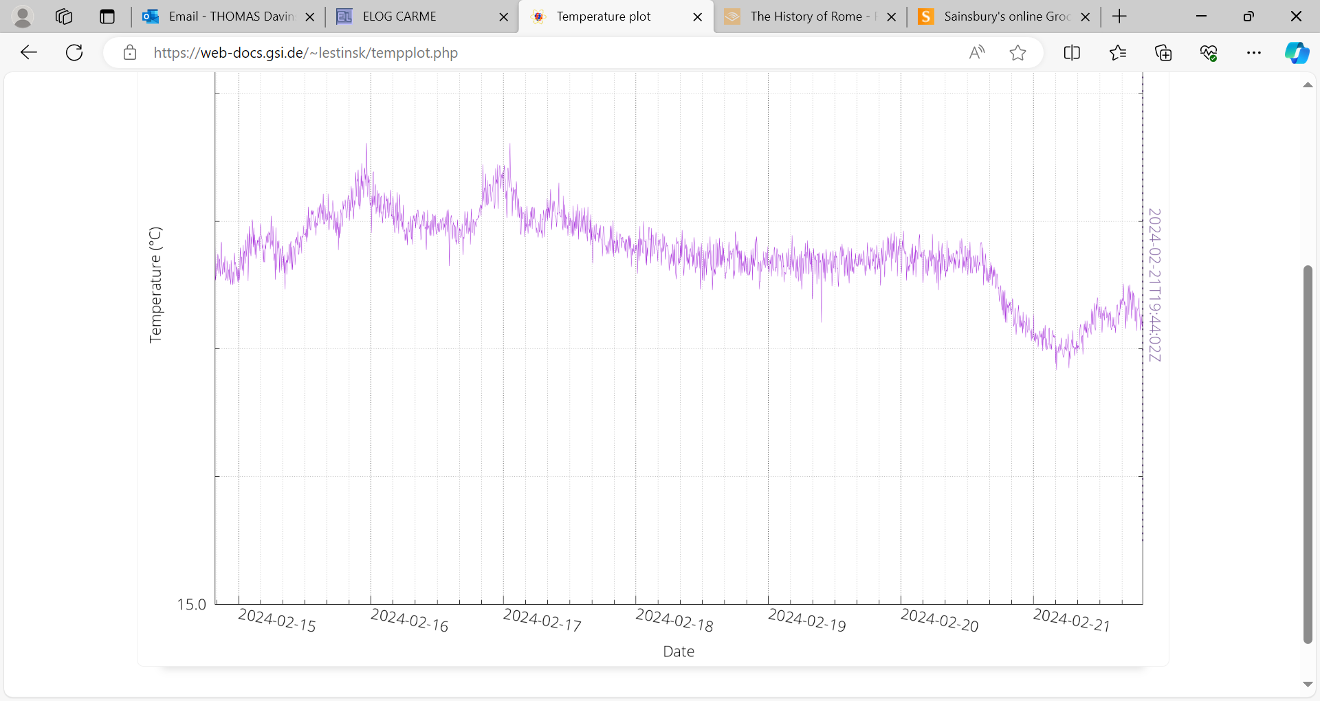
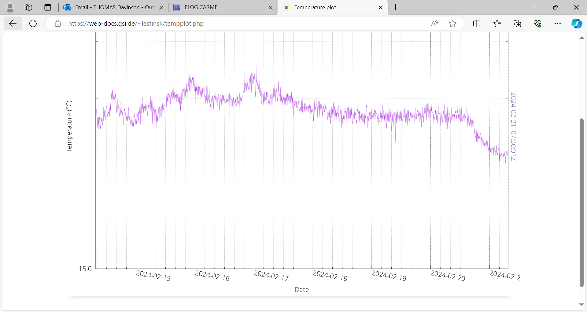
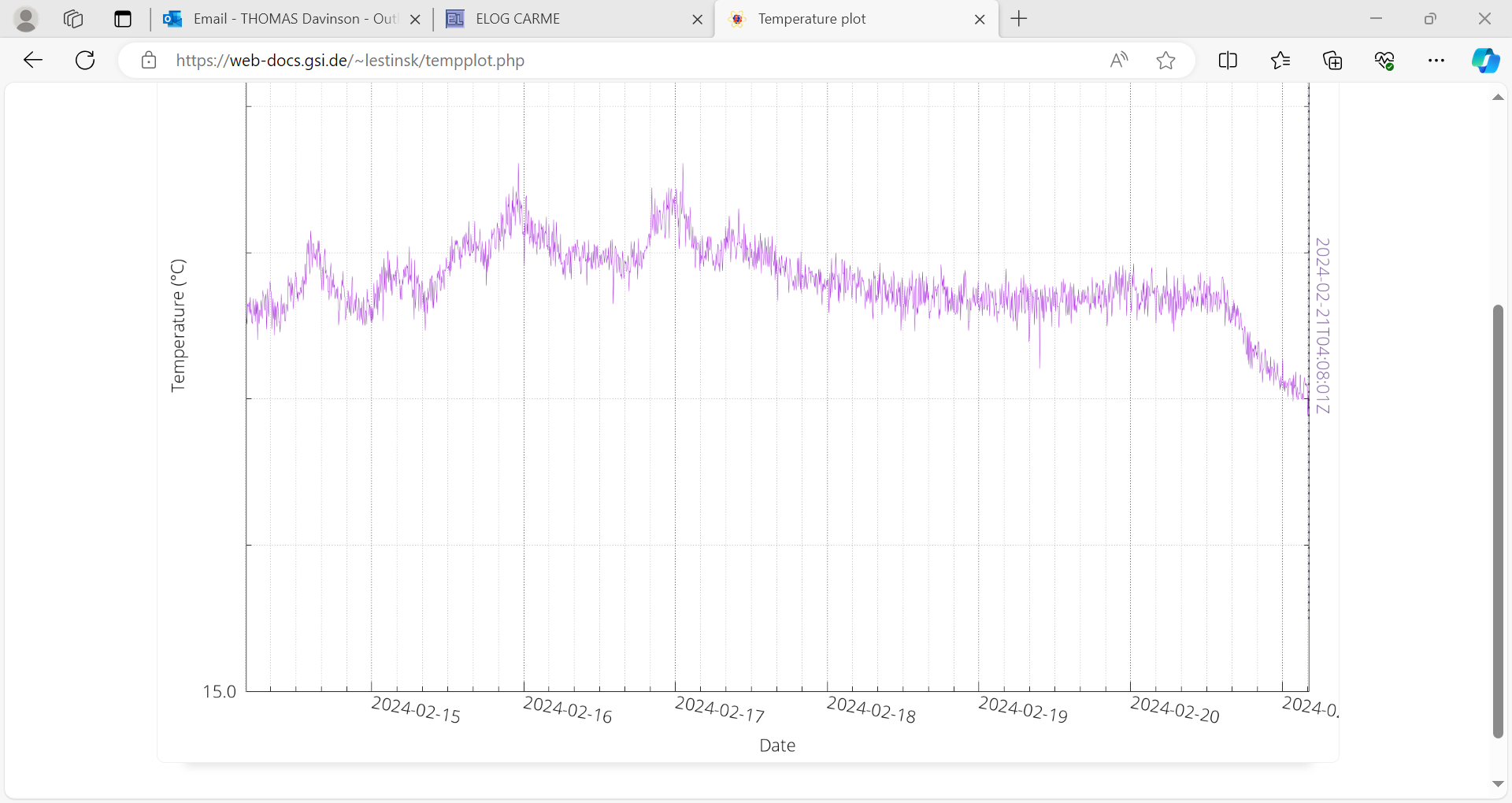
TD | Wedneday 21 February |
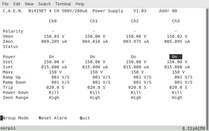
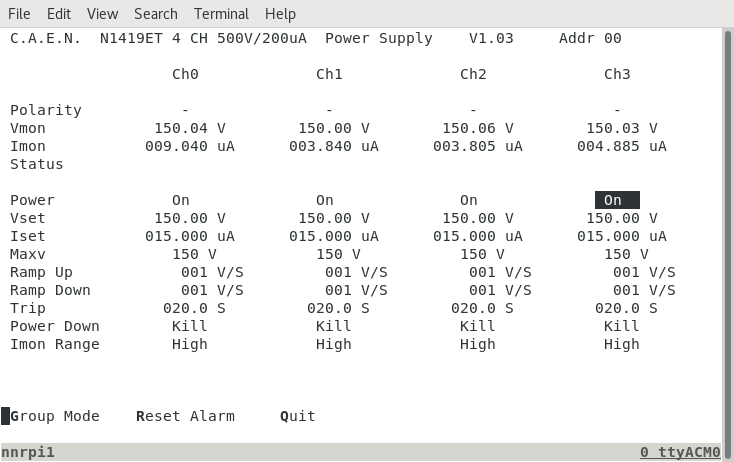
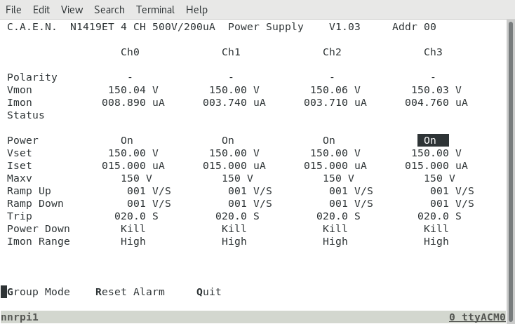
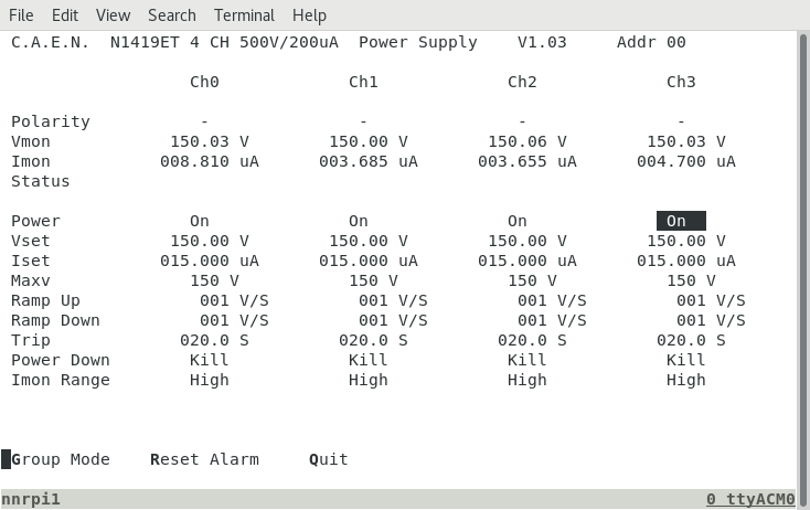
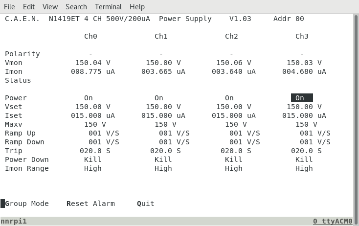
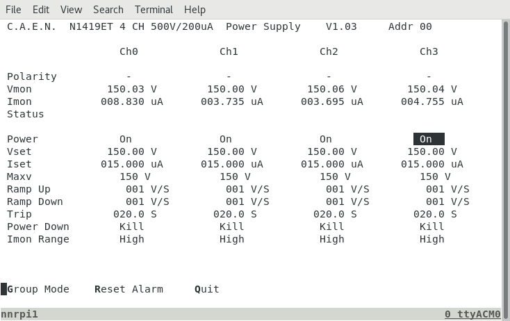
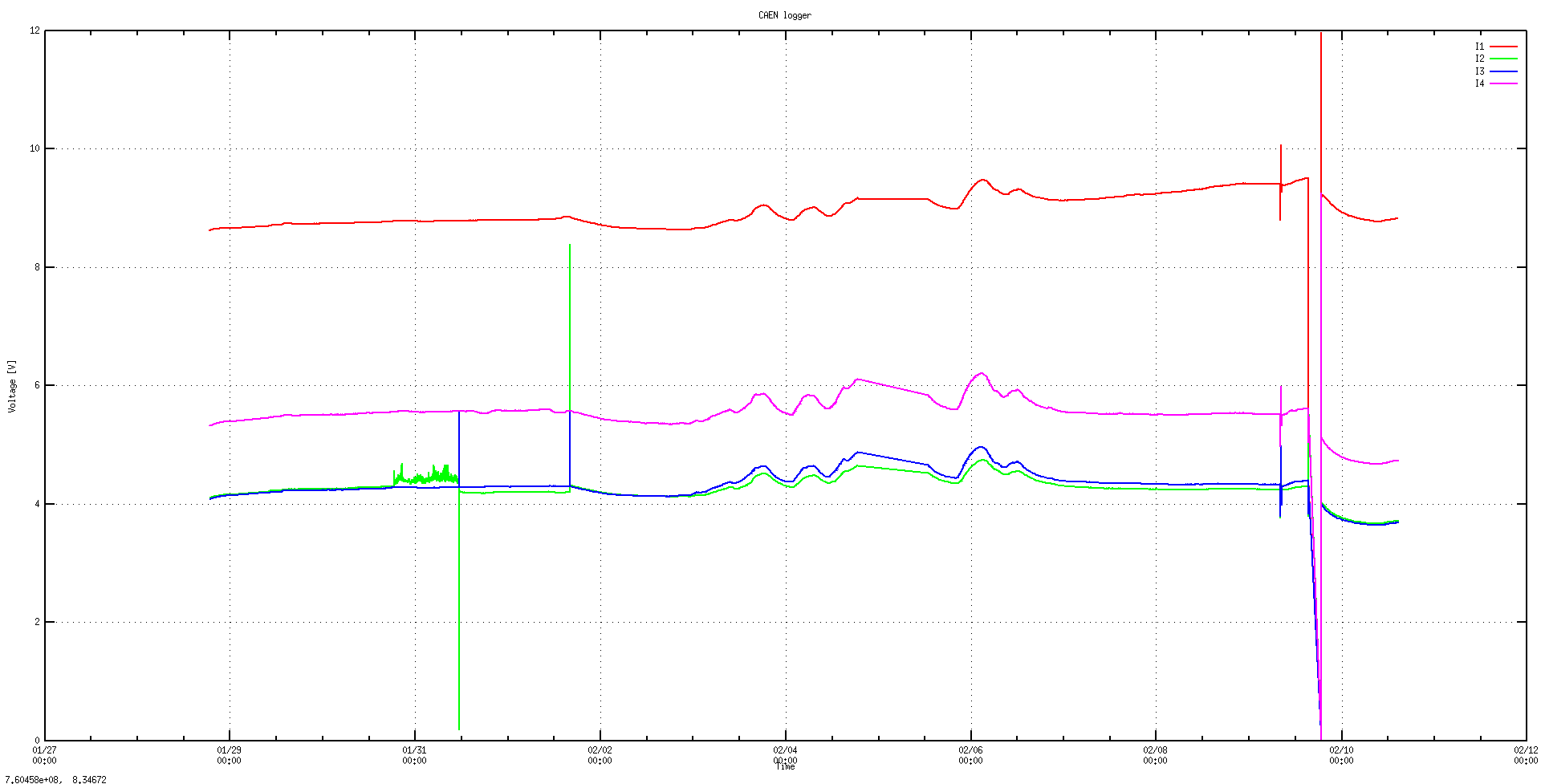
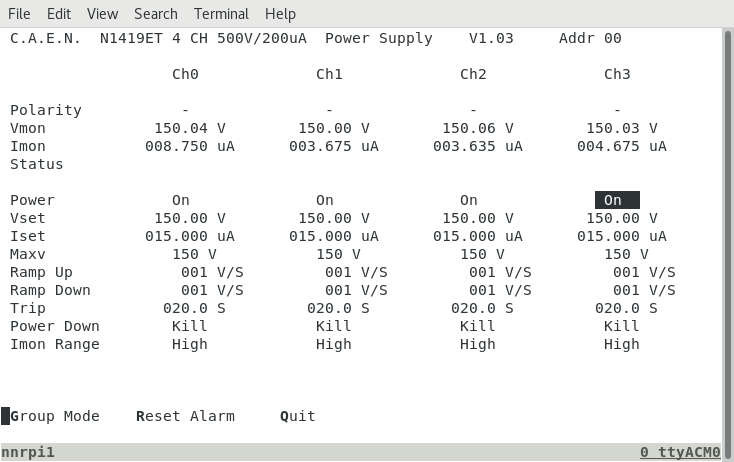
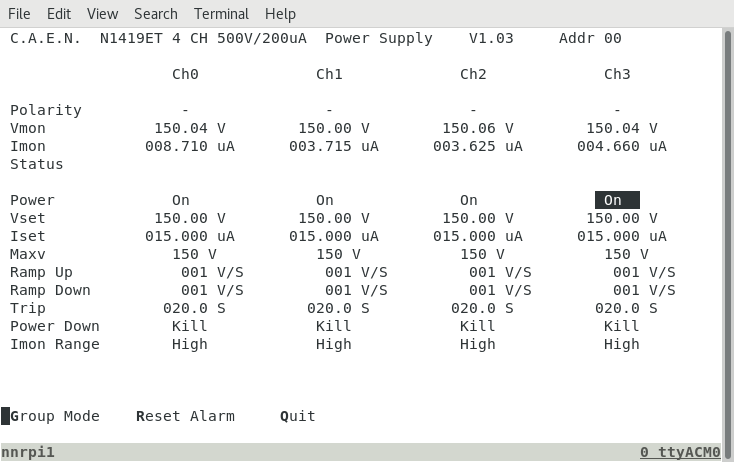
10.54 23.2.24 Bias OFF |
| Attachment 1: Screenshot_from_2024-02-20_18-40-08.png
|
|
| Attachment 2: Screenshot_from_2024-02-20_21-30-08.png
|
|
| Attachment 3: Screenshot_from_2024-02-21_01-00-13.png
|
|
| Attachment 4: Screenshot_from_2024-02-21_05-10-07.png
|
|
| Attachment 5: Screenshot_from_2024-02-21_08-30-06.png
|
|
| Attachment 6: Screenshot_from_2024-02-21_20-45-58.png
|
|
| Attachment 7: Screenshot_from_2024-02-21_20-46-12.png
|
|
| Attachment 8: Screenshot_from_2024-02-22_00-51-21.png
|
|
| Attachment 9: Screenshot_from_2024-02-22_14-02-29.png
|
|
| Attachment 10: Screenshot_from_2024-02-22_14-02-44.png
|
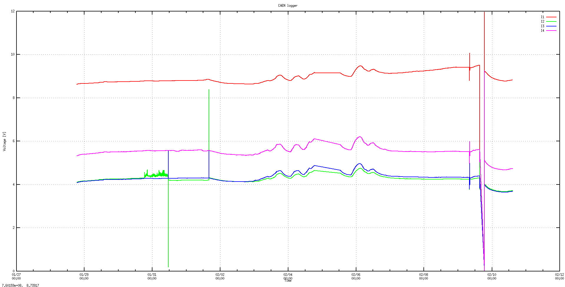
|
| Attachment 11: Screenshot_from_2024-02-22_19-00-08.png
|
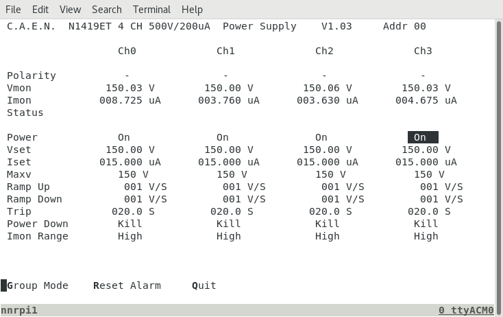
|
| Attachment 12: Screenshot_from_2024-02-22_19-00-31.png
|
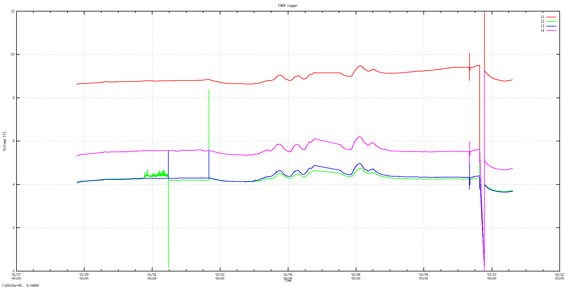
|
| Attachment 13: Screenshot_from_2024-02-23_11-53-32.png
|
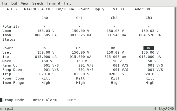
|
| Attachment 14: Screenshot_from_2024-02-23_11-53-45.png
|
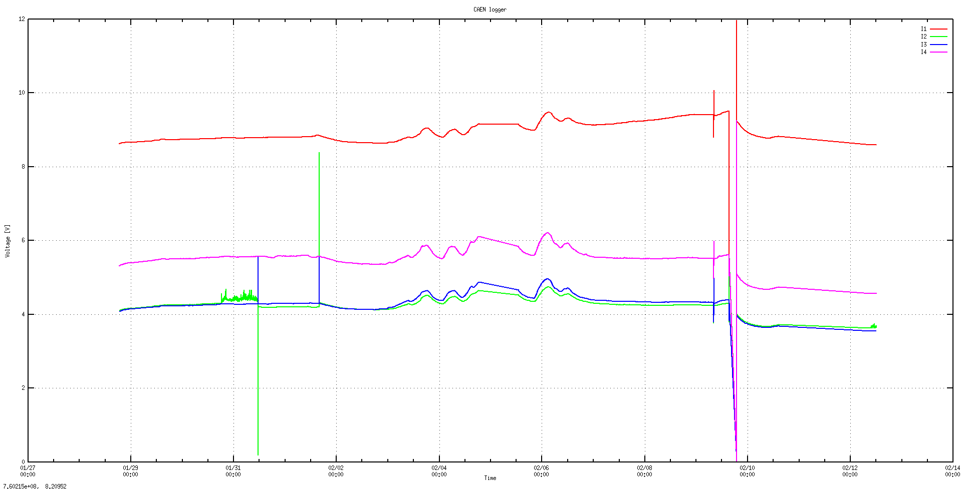
|
| Attachment 15: Capture_10.55.PNG
|
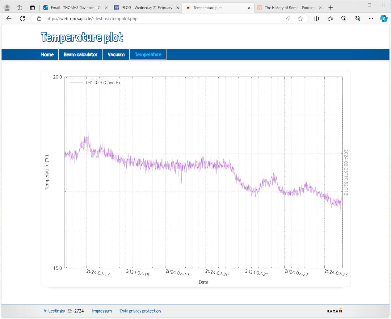
|
| Attachment 16: Capture_18.00.PNG
|
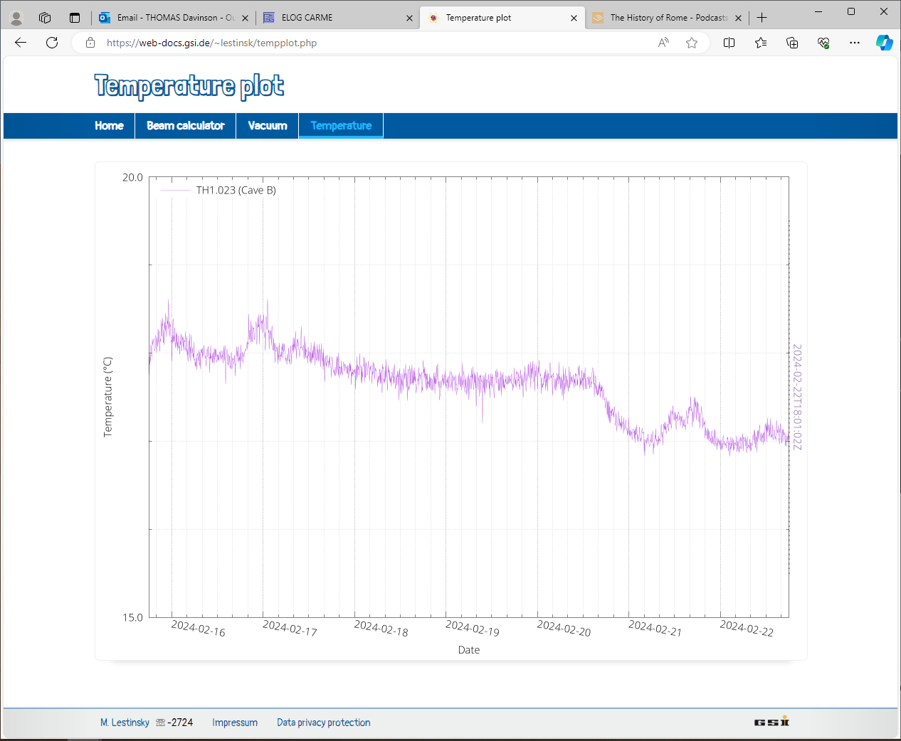
|
| Attachment 17: Capture_13.04.PNG
|
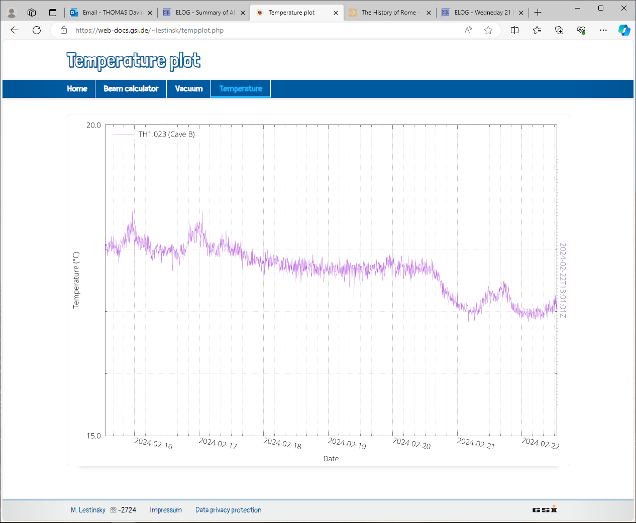
|
| Attachment 18: Capture_23.52.PNG
|
|
| Attachment 19: Capture_19.46.PNG
|
|
| Attachment 20: Capture_07.30.PNG
|
|
| Attachment 21: Capture_04.10.PNG
|
|
| Attachment 22: Capture_00.00.PNG
|
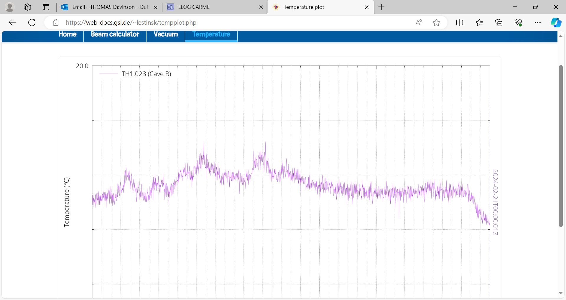
|
| Attachment 23: Capture_20.30.PNG
|
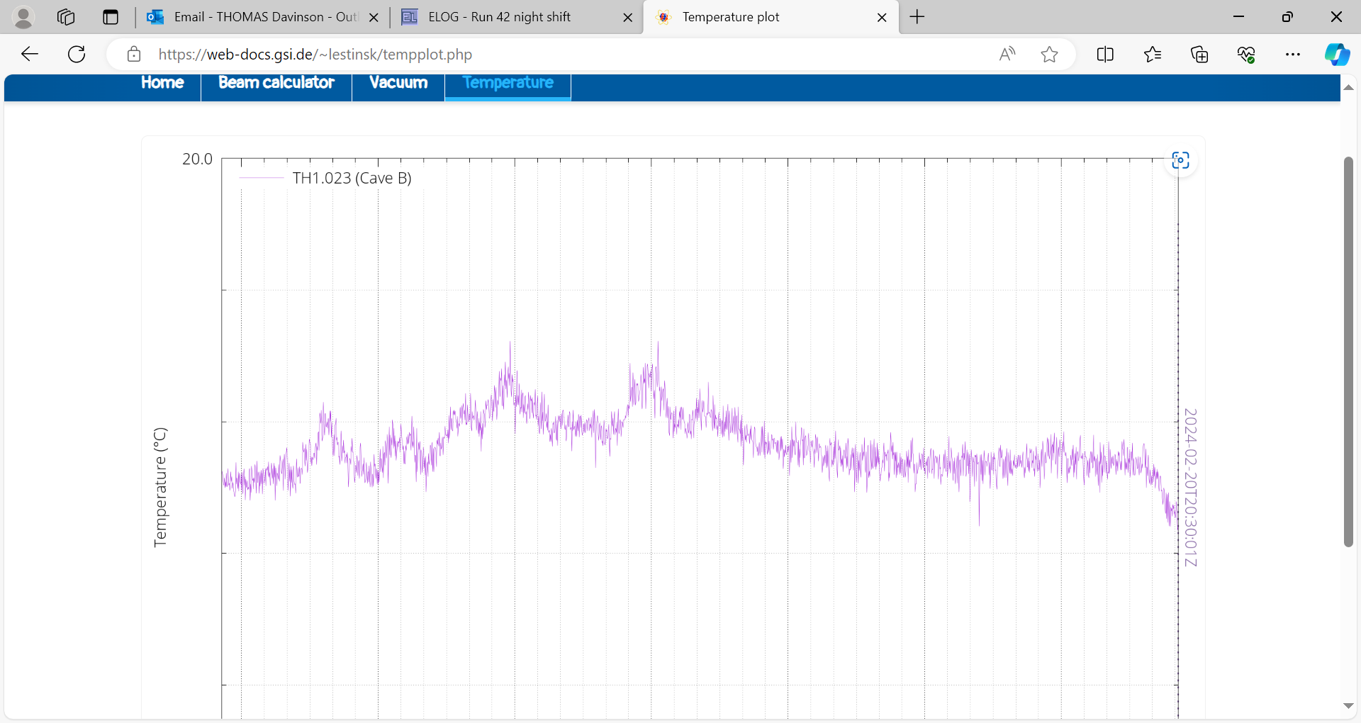
|
| Attachment 24: Capture_17.40.PNG
|
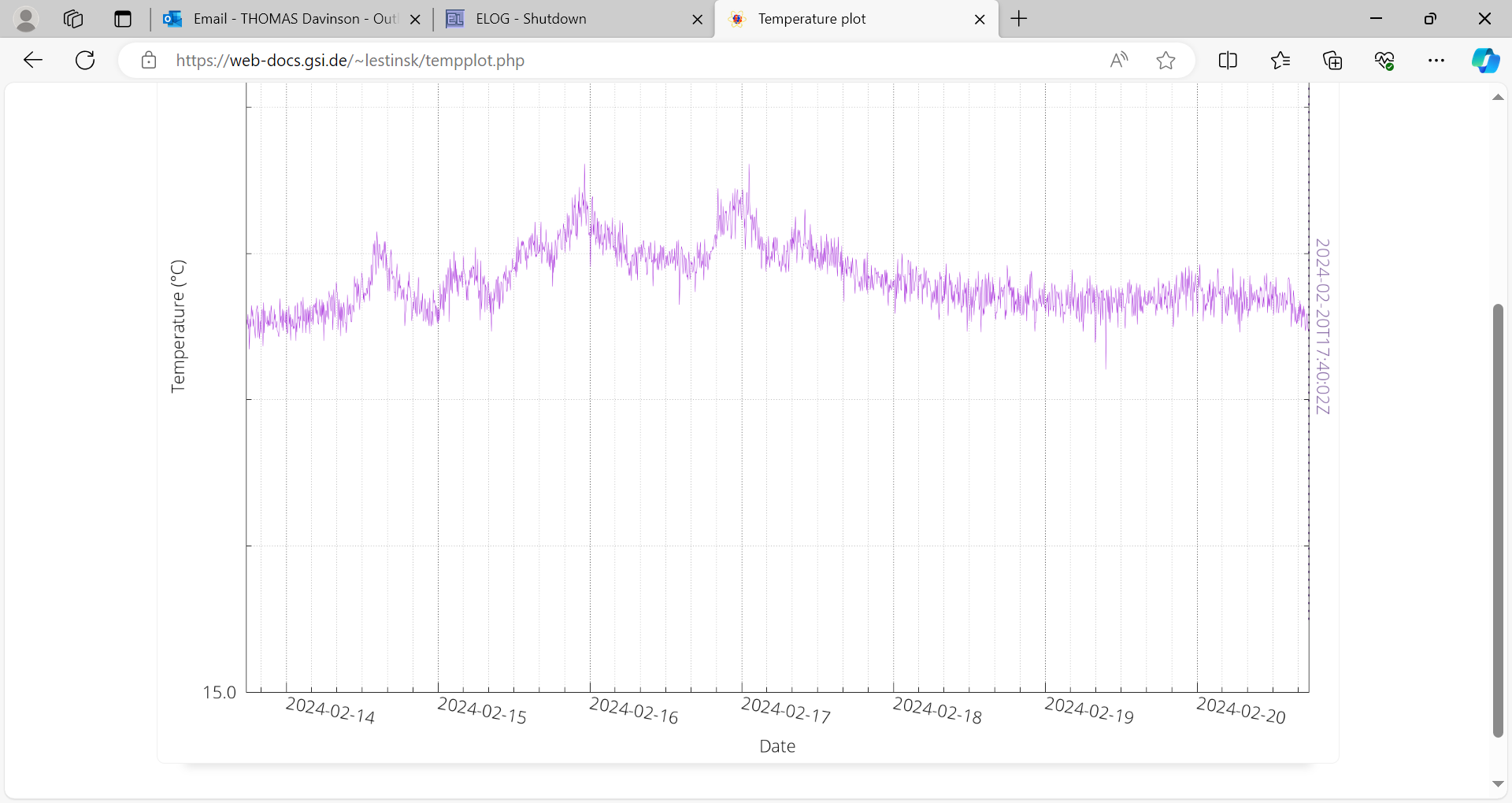
|
|
175
|
Wed Jan 26 19:16:18 2022 |
JM, OH | Water cooling, FEE MAC address |
Water cooling has been connected to the FEE's. Flow meter installed to outlet manifold by way of two right angled pieces. No leaks observed rom any points in the coolant loop, loop will be bled using taps tomorrow. Water turned OFF overnight.
FEE's powered up with the MAC addresses of each read. 1 is the very bottom FEE and 8 the very top. FEE's have also labelled with the MAC addresses.
1. 0xd8 0x80 0x39 0x42 0x0d 0x0c
2. d8:80:39:41:d8:2b
3. d8:80:39:41:d0:05
4. 0xd8 0x80 0x39 0x41 0xd7 0xc2 (Now AIDA 5 see elog 185)
5. 0xd8 0x80 0x39 0x41 0xb4 0x0b (Now AIDA 4 see elog 185)
6. d8:80:39:41:d8:20
7. 0xd8 0x80 0x39 0x41 0xb4 0x16
8 .0xd8 0x80 0x39 0x41 0xd7 0xcd
MACB firmware has been updated by Nic
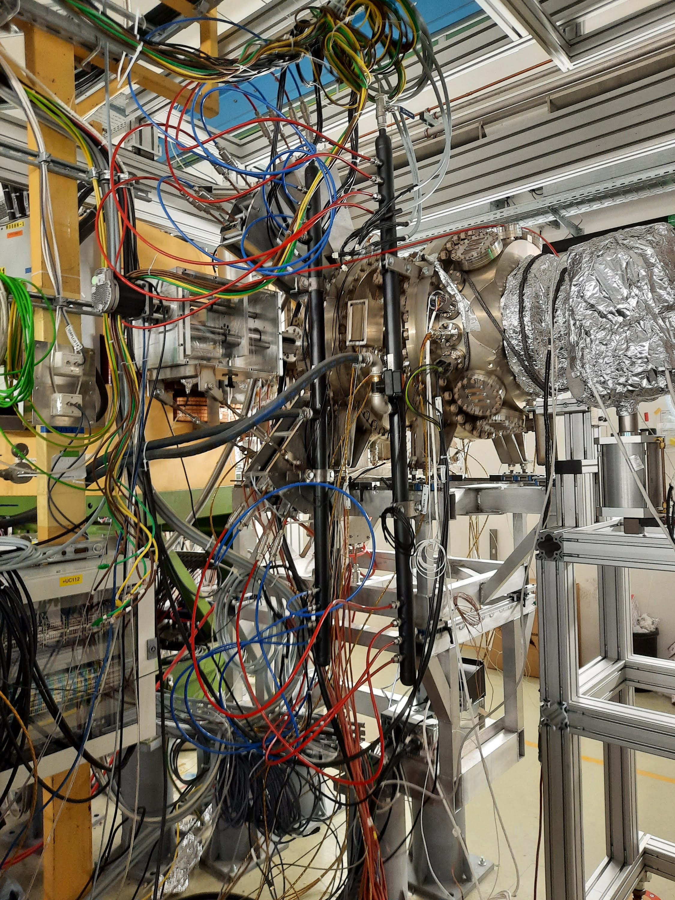
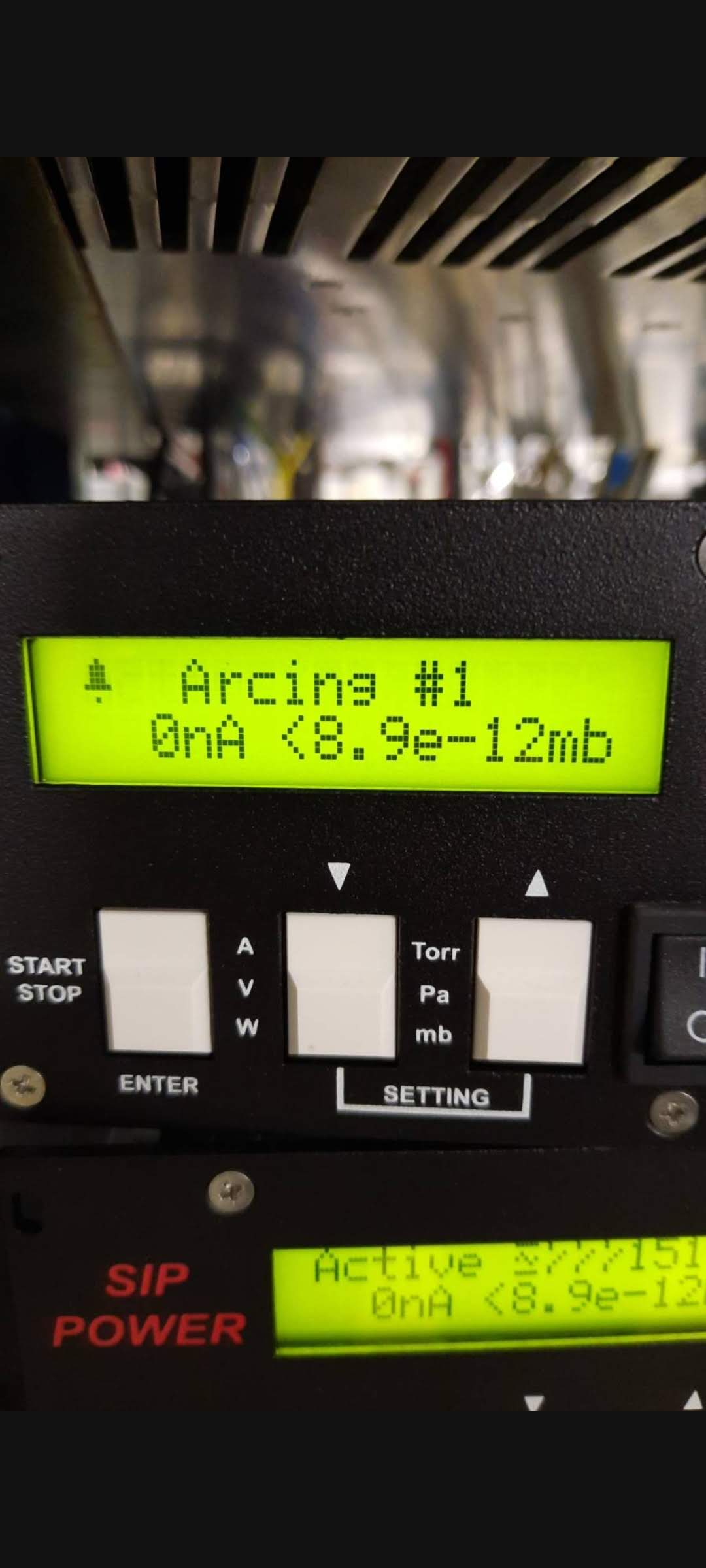
One ion pump showed the warning 'arcing' (see attached photo) and was subsequently turned OFF. Most likely cause is the cable was moved during installlation of the flow meter as the pump showed no error this morning. The pump was turned back ON, no error observed -> cable not damaged but sensitive to movement. |
| Attachment 1: 20220126_162435.jpg
|

|
| Attachment 2: 20220126_162448.jpg
|
|
| Attachment 3: 20220126-142809.jpg
|
|
|
703
|
Fri May 30 07:27:41 2025 |
CB LB JM NP EM | Waiting for deuterium |
08:27
No run going.
Temperatures OK - attach
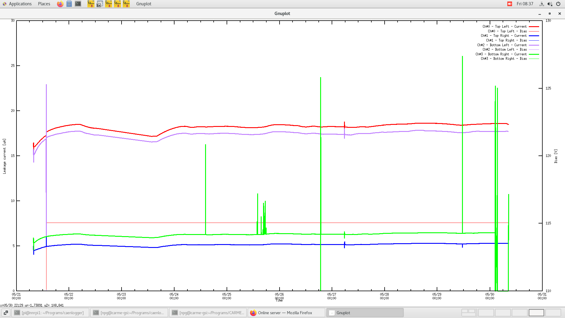
Attempting to bias channel 3 again. Slowly ramping up.
V = 60, I = 5.3
V = 70, I = 6.1
V = 80, I = 9.0 --> 6.2 (unstable). Decreasing bias.
V = 70, I = 6.0 (stable again)
Leaving at 70 V for a while to condition (?)
Resetting the gnuplot graph. Old caen_current.dat moved to G22-205-caen_current.dat and copied in /TapeServer/G22-205
10:10
Temperatures OK
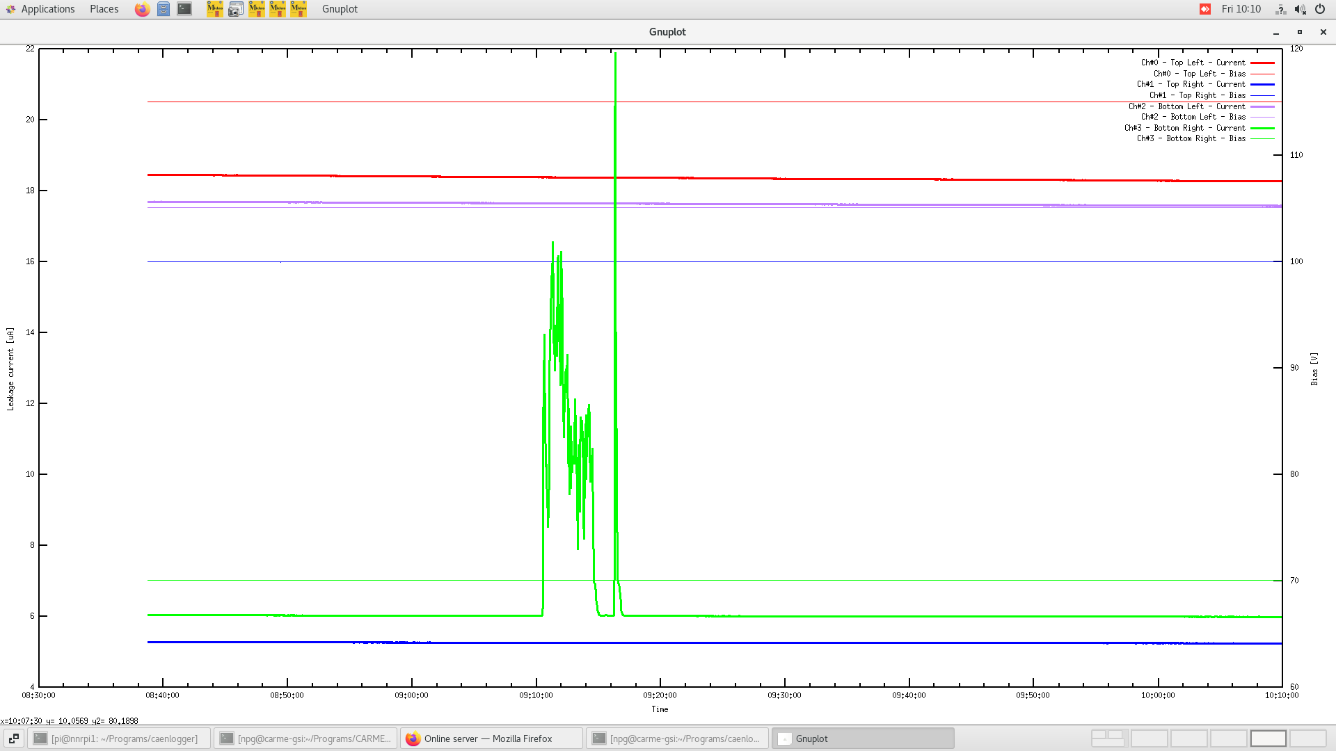
Leakage current on channel 3 showed some issues, back to stable. See attached.
11:00
Temps OK
Leakage current stable.
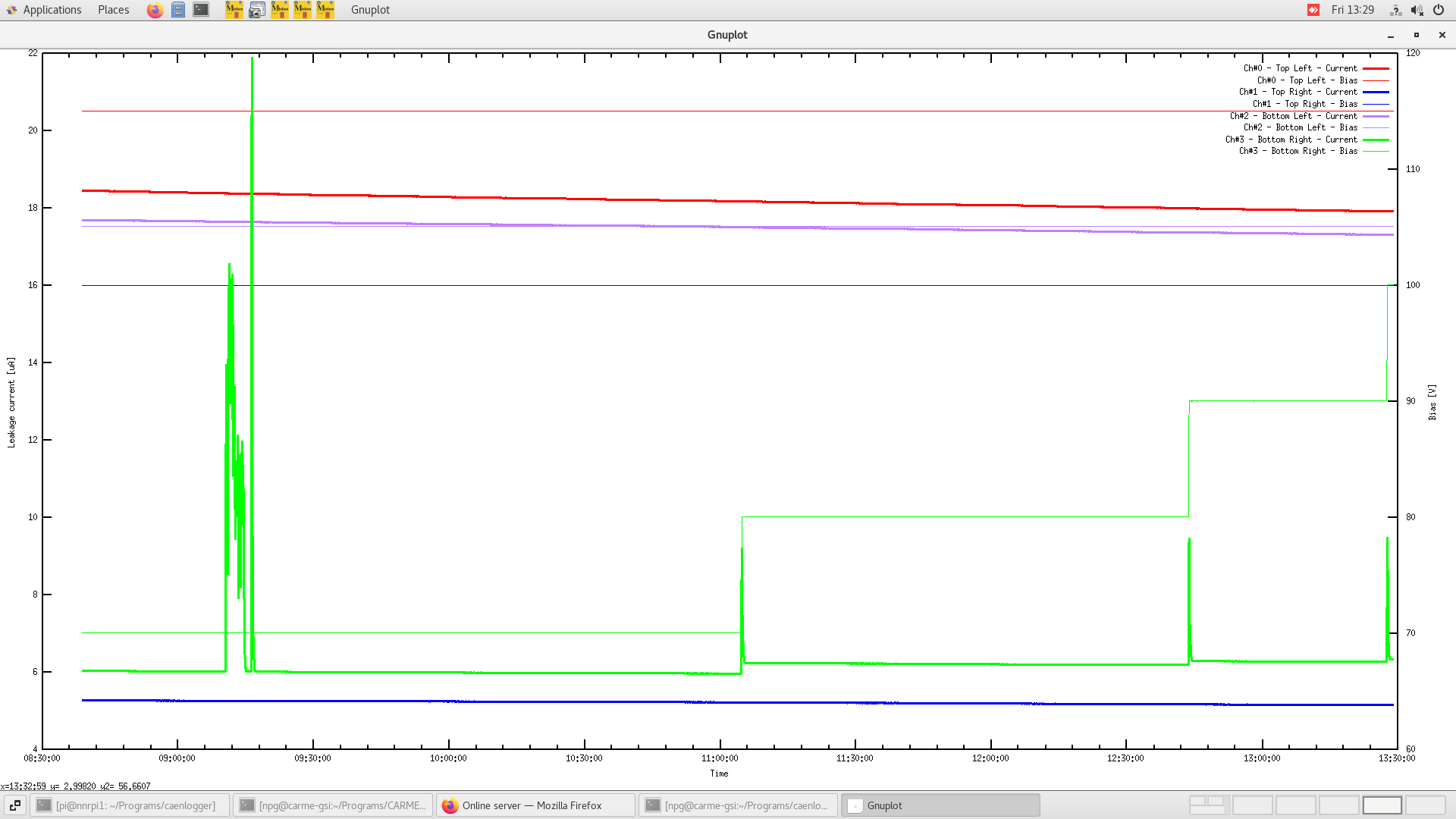
Increased bias on channel 3 to 80 V. I = 6.2 uA stable. Leaving for a while.
12:45
Temps OK
Leakage current stable
Increased bias on channel 3 to 90 V. I = 6.3 stable. Leaving for a while.
13:30
Temps OK
Leakage current stable.
Increased bias on channel 3 to 100V. I = 6.3 stable. Hopefully it holds until the end of the beam time.
20:00
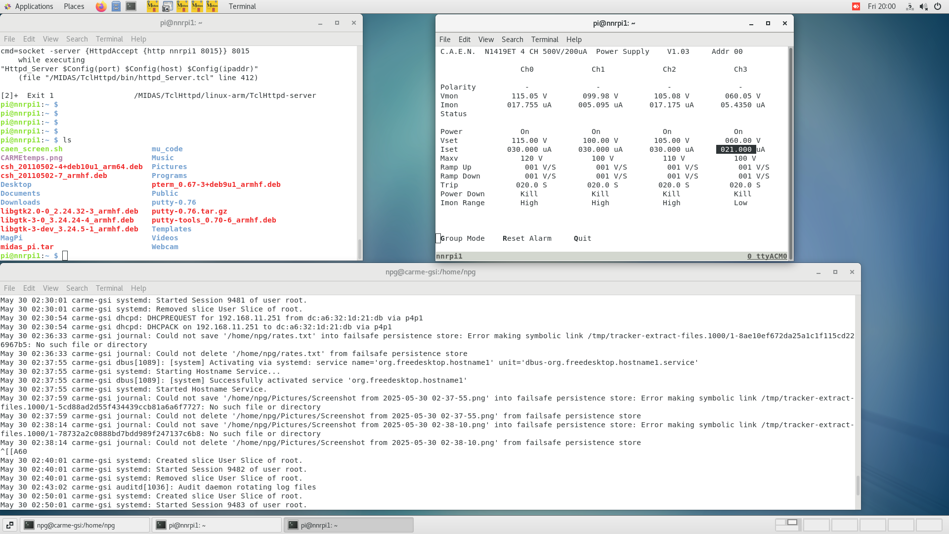
Leakage current on channel 3 had issues again and bias was reduced to 50 V. Remained stable. Turned to 60 V now. Still stable. See attachement.
FEEs on detector for -> MEC
Temps OK - attach
Checks as before - attach
Rates OK (four fees not counting as expected) - attach
Deuterium beam in the ring at 2 MeV/A approx 2E8 pps, significant H2+ contamination.
Deuterium target working, fluctuating around 5E12-1E13 atoms/cm2
Vacuum in YR09 - 3E-10 mbar
Beginning beam-target overlap measurements soon. |
| Attachment 1: Screenshot_from_2025-05-30_08-28-08.png
|

|
| Attachment 2: Screenshot_from_2025-05-30_08-37-17.png
|
|
| Attachment 3: Screenshot_from_2025-05-30_10-10-12.png
|
|
| Attachment 4: Screenshot_from_2025-05-30_13-29-57.png
|
|
| Attachment 5: Screenshot_from_2025-05-30_20-00-13.png
|

|
| Attachment 6: Screenshot_from_2025-05-30_20-00-17.png
|
|
| Attachment 7: Screenshot_from_2025-05-30_20-00-27.png
|

|
| Attachment 8: Screenshot_from_2025-05-30_20-00-37.png
|

|
|
116
|
Mon Oct 11 11:24:16 2021 |
RSS TD ML | Valve support and cable labeling |
Split funnels were given to Oemer for cleaning. Have received them back after lunch.
Valve support is installed again (see picture 1).
Ion pump was connected but not activated. Michael will help in doing so. No vacuum support to help will RGA. Will proceed without it.
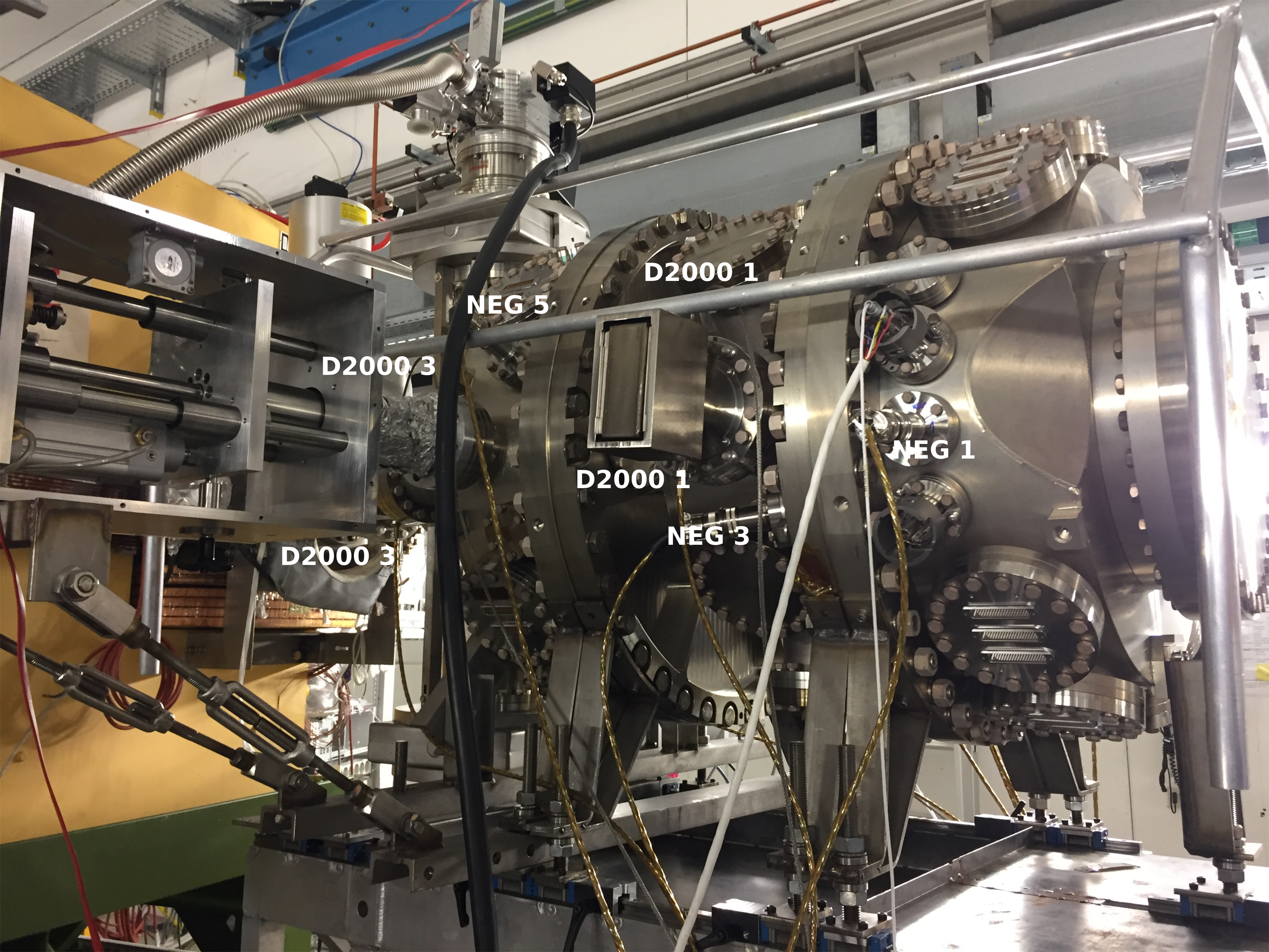
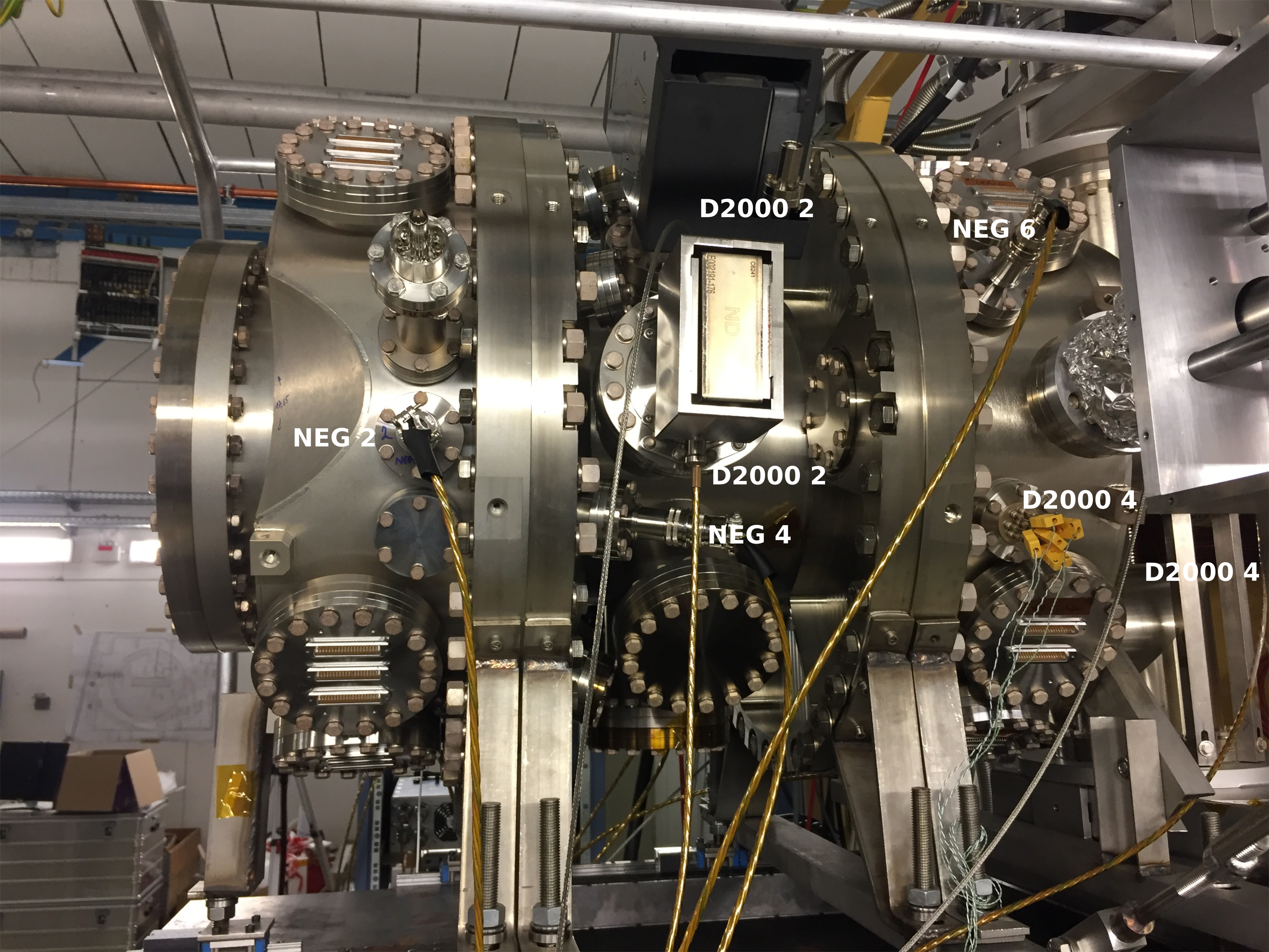
Neg and ion cables were labeled (see pictures 2 and 3).
Chamber was vented using nitrogen.
|
| Attachment 1: IMG_4962.JPG
|

|
| Attachment 2: IMG_4969.JPG.svg
|
|
| Attachment 3: IMG_4968.JPG.svg
|
|
|
240
|
Tue Feb 22 18:23:02 2022 |
David. Yury | Vacuum problem |
At 19:10 the vacuum has increased suddenly everywhere in the ring, roughly a factor 1.5. |
|
80
|
Fri Sep 24 09:44:58 2021 |
JM ML | Vacuum gauge readout |
The analog readout of the Combivac controller for the IE514 ion gauge has been set up, readings are plotted to http://web-docs.gsi.de/~lestinsk/vacplot.php. Readings and plot should be updated every minute. |
|
441
|
Wed Sep 13 15:00:39 2023 |
ML | Vacuum and Heater temperature plots from Grafana |
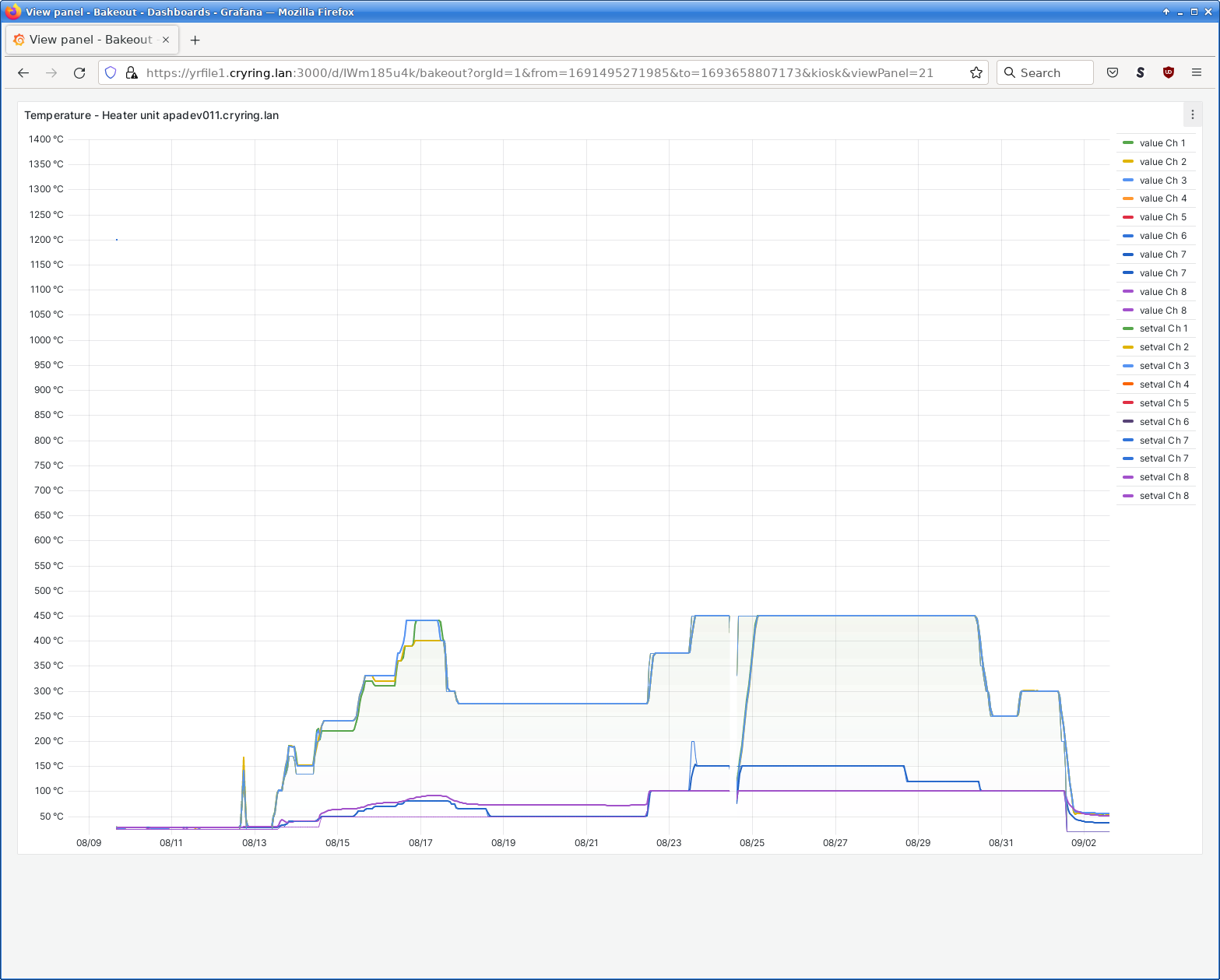
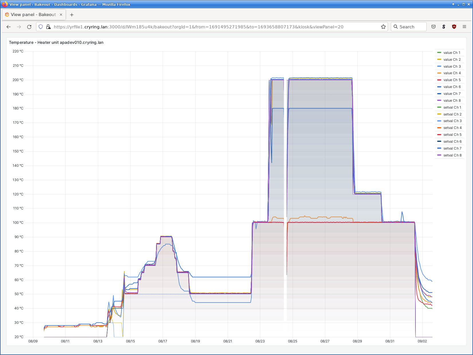
Attached are the plotted curves from vacuum and heater temperature (actual and set values from ISOHEAT controllers) during the bakeout process. Channel assignment as per post 433. |
| Attachment 1: Screenshot_2023-09-13_15-56-34.png
|

|
| Attachment 2: Screenshot_2023-09-13_15-58-06.png
|

|
| Attachment 3: Screenshot_2023-09-13_15-59-37.png
|
|
| Attachment 4: Screenshot_2023-09-13_15-59-01.png
|
|
| Attachment 5: Screenshot_2023-09-13_15-58-31.png
|

|
|
396
|
Wed May 10 19:06:18 2023 |
RSS, TD | V-I test |
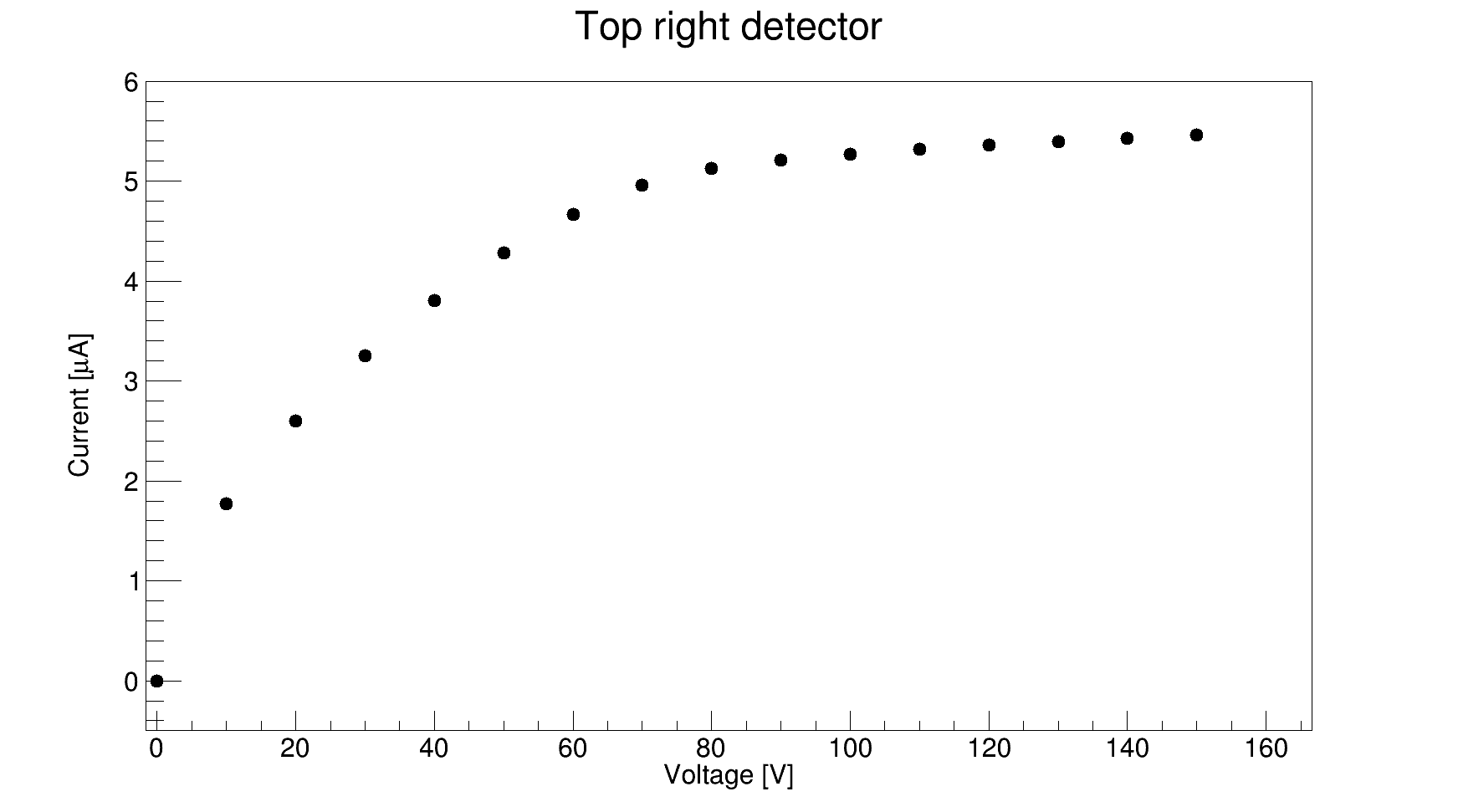
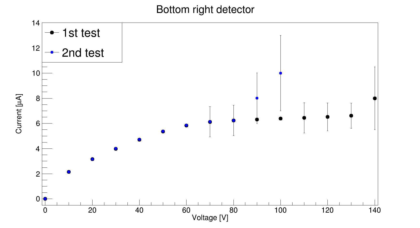
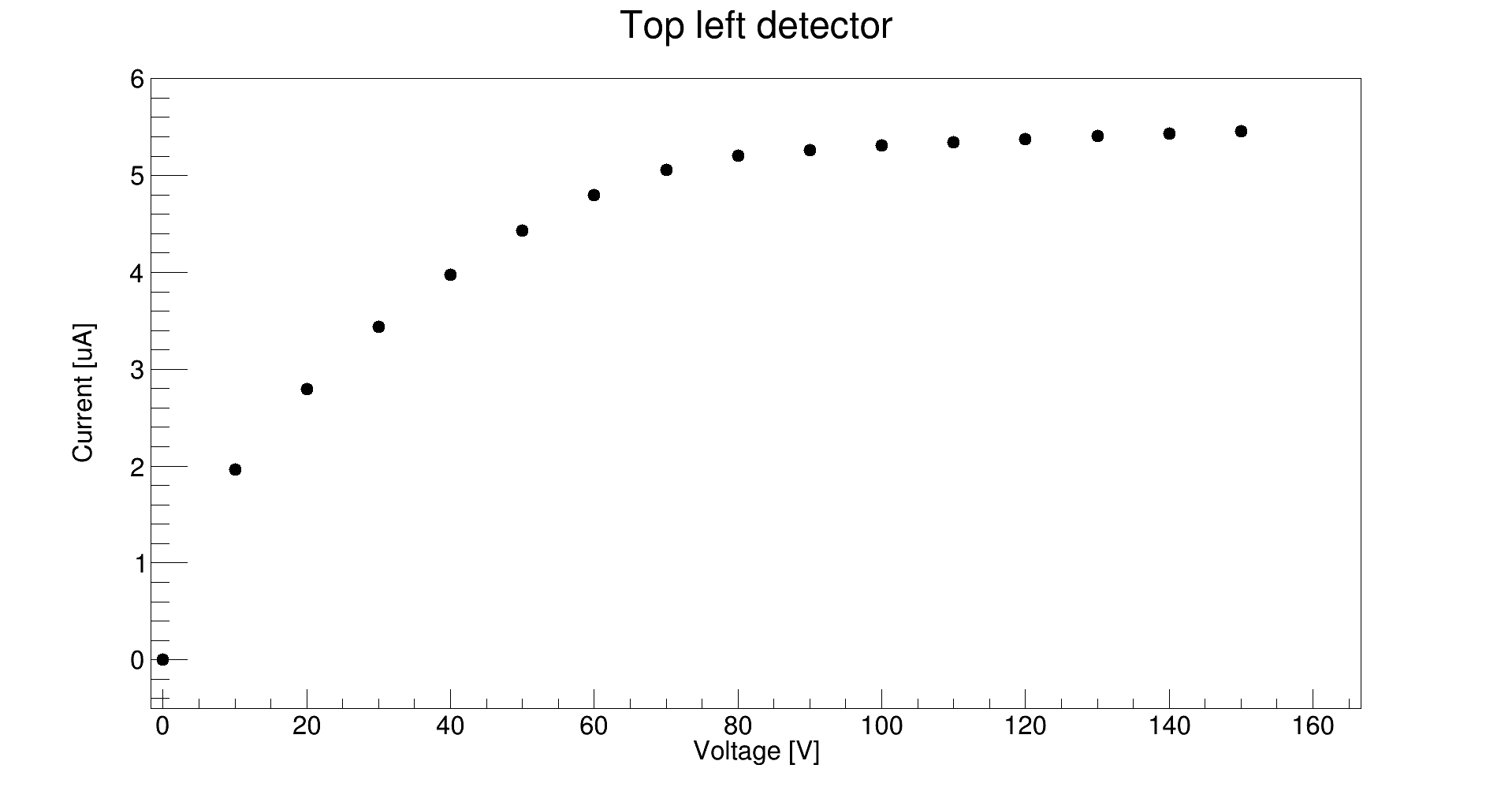
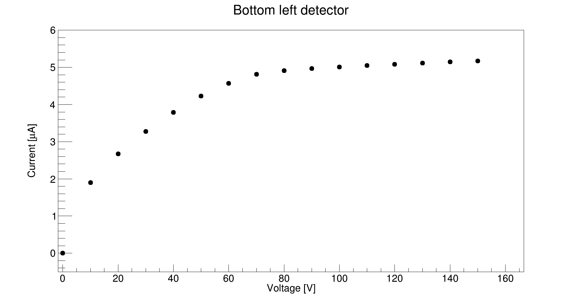
To test the detectors, adaptors were installed on the feed through flanges. A negative bias voltage was applied in steps of 10 V from 0 to 150 V. The V-I plots are attached for the four detectors. Three detectors - top right, top left, and bottom left (in the direction of the beam) - are fine. For the bottom right detector (in the direction of the beam), the current was fluctuating and was considerably high (1st test). The adaptors connecting to this detector were removed and checked by applying the bias voltage which showed zero current for voltages ranging from 0 to - 150 V, confirming the adaptors to be fine. They were then exchanged by other adaptors and the V-I test was repeated again (2nd test) with fluctuating and high current values. One of the flanges connecting to this detector was found to be light-tight. These tests were done at an ambient temperature of 21 degrees. Also, we couldn't find the rest of the three SHV to 2x Lemo 00 cables for the detector HV. |
| Attachment 1: detector_1.png
|

|
| Attachment 2: detector_2.png
|
|
| Attachment 3: detector_3.png
|
|
| Attachment 4: detector_4.png
|

|
|
397
|
Thu May 11 21:22:54 2023 |
RSS, TD | V-I test |
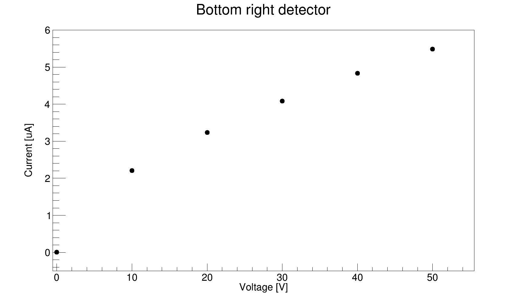
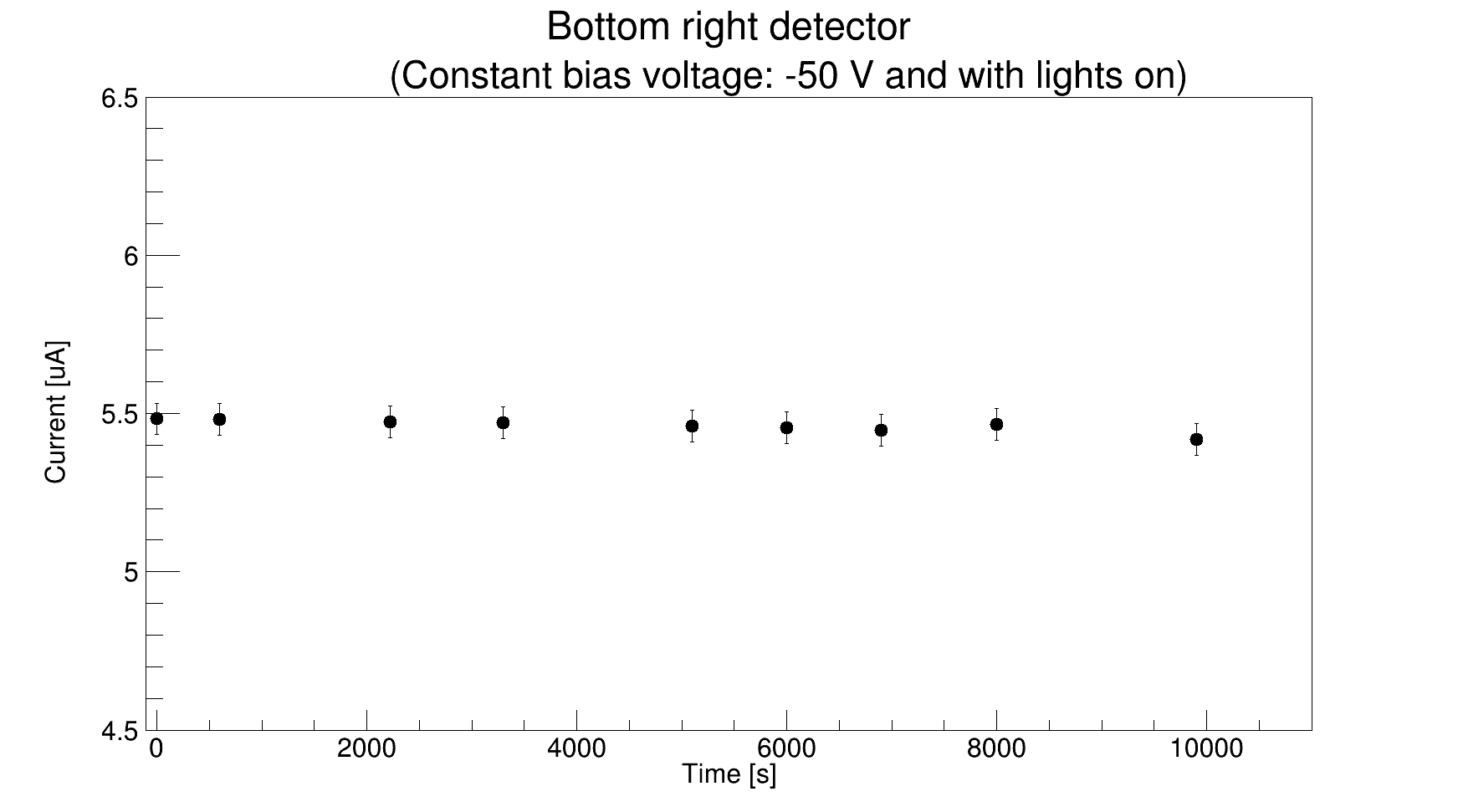
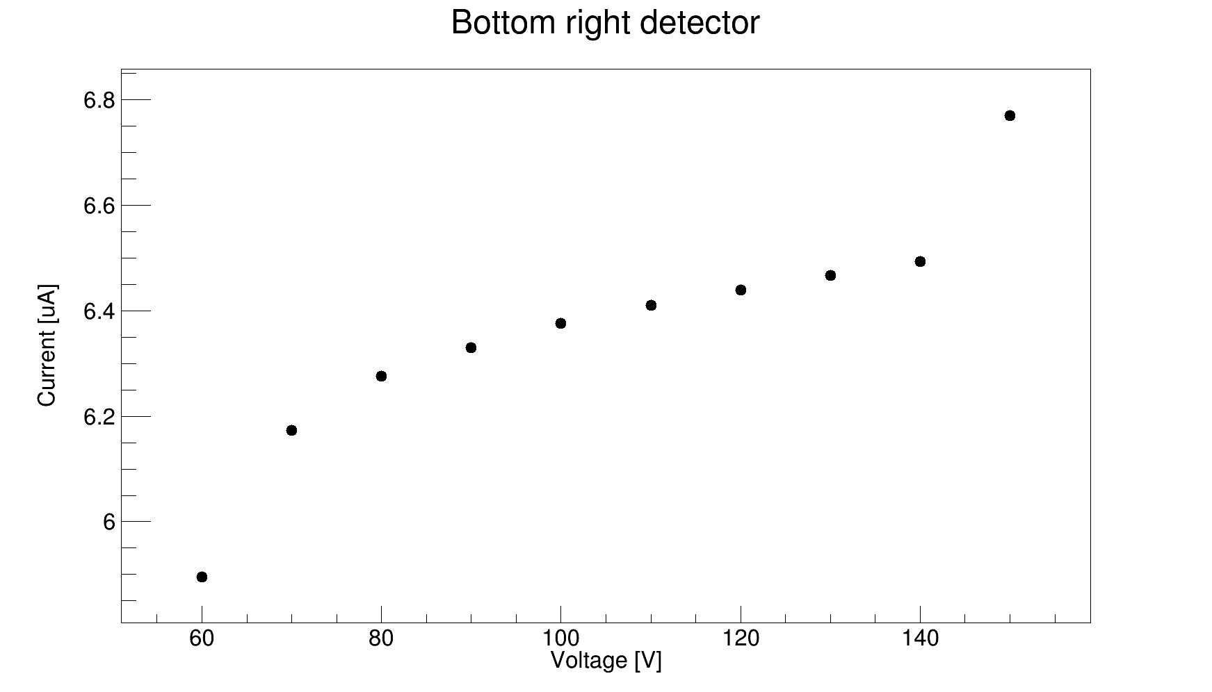
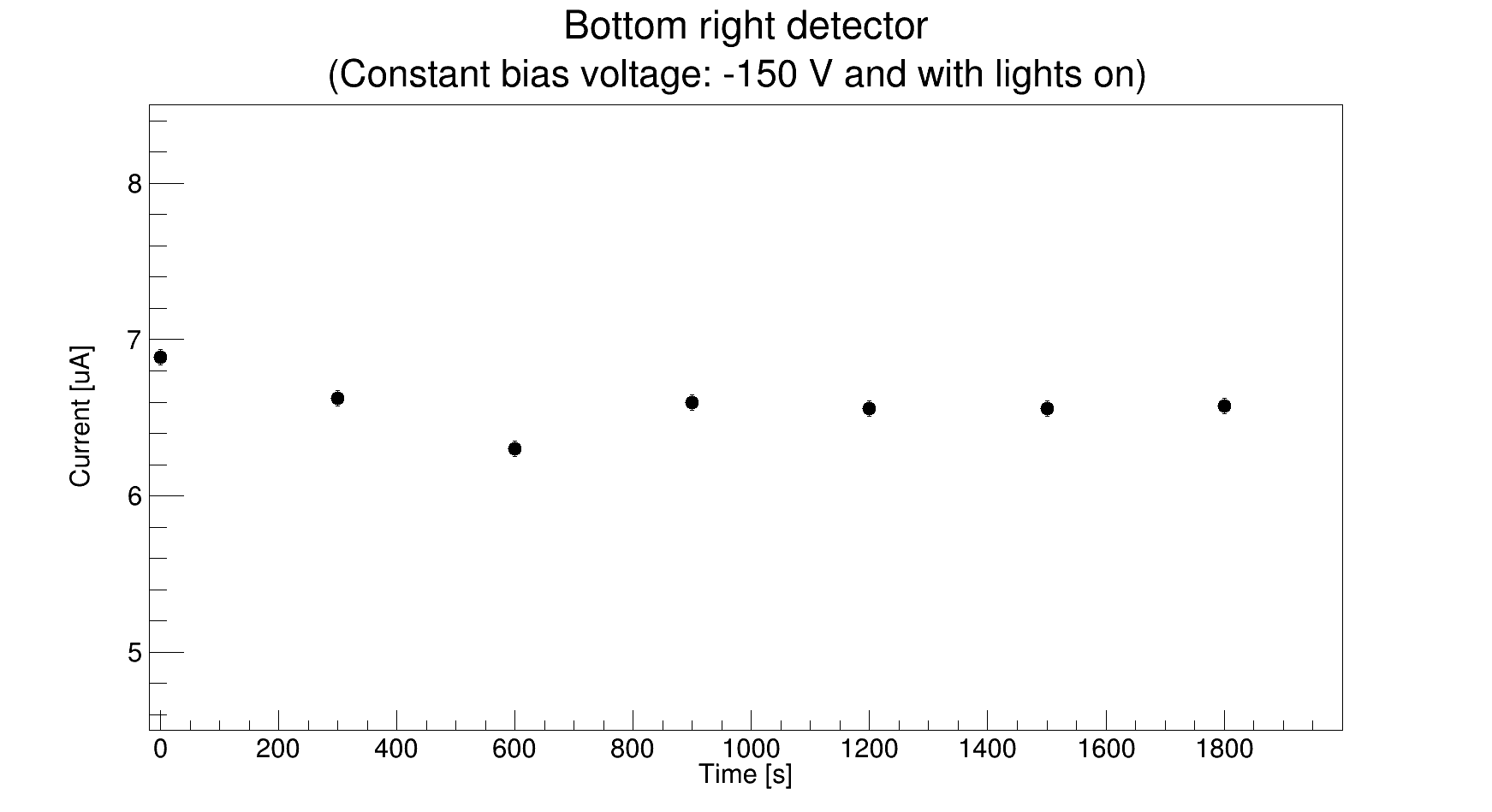
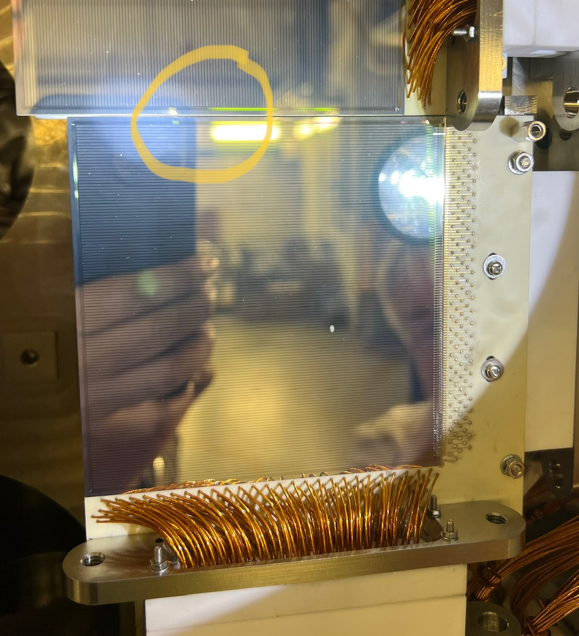
Today, the foil was opened, the pins on the bottom right detector were checked and looked fine, the right-hand arm was moved a bit in and then out, and the foil was tightly closed again. The negative bias voltage was applied from 0 to 50 V in steps of 10 V. During the measurement, the lights in the cave were switched off to ensure no leakage current from the light*. The results are shown in Attachment 1. To condition the detector, it was left at a negative bias voltage of 50 V for ~ 3 hours with lights on. No increase in current was seen (see Attachment 2), indicating the chamber was nicely covered with foil. Then the negative voltage was increased from 60 V to 150 V in steps of 10 V. No large current readings, like yesterday, were seen today (see Attachment 3). The detector was then left at -150 V for ~ 30 minutes with the current to be nearly stable with fluctuations in the range of 70-100 nA. The foil was then taken off to check if there are any dust particles on the detector surface. As can be seen in Attachment 6, some dust particle was found at the bias/multi-guard ring (MGR) boundary structures of the DSSSD. The area was then nicely cleaned with isopropanol + lab tissue wipe (see Attachment 7) and the chamber was covered with aluminum foil again. The negative bias voltage was applied from 0 to 150 V in steps of 10 V again and the results can be seen in attachment 5, indicating the response of the detector to be normal, unlike yesterday. Before calling the day off, the detector was left at -150 V overnight.
* Every time, before switching off the lights, it was checked that no one else was in the cave. |
| Attachment 1: test1.png
|
|
| Attachment 2: test2.png
|
|
| Attachment 3: test3.png
|
|
| Attachment 4: test4.png
|
|
| Attachment 5: test5.png
|

|
| Attachment 6: IMG_8800.jpg
|
|
| Attachment 7: IMG_8804.jpg
|

|
|
398
|
Fri May 12 16:24:20 2023 |
RSS, TD | V-I test |
Since yesterday evening, the bottom right detector was at -150 V. In the morning, the current was quite stable ~ 6.77 uA. The bias was switched off, the foils opened, both of the detector arms were moved in and out three times, and the chamber was tightly covered again. A negative bias voltage was applied from 0 to 150 V in steps of 10 V one by one to all four detectors, and the V-I results can be seen in Attachments 1-4. All detectors seem to be fine. The variation of the current with time at a constant bias voltage of -150 V was checked for all detectors and the results are in Attachments 5-8. Also, with an applied bias voltage of -150 V to the bottom right and left detector, the detector arms were moved in and out three times which showed a variation of 1-2 nA and 1 nA in the leakage current. For further conditioning of the bottom right detector, it is again left with a negative bias voltage of 150 V over the weekend. |
| Attachment 1: detector_1.png
|
|
| Attachment 2: detector_2.png
|

|
| Attachment 3: detector_3.png
|

|
| Attachment 4: detector_4.png
|
|
| Attachment 5: detector_1_variation.png
|

|
| Attachment 6: detector_2_variation.png
|

|
| Attachment 7: detector_3_variation.png
|

|
| Attachment 8: detector_4_variation.png
|

|
|
433
|
Sat Aug 12 11:57:51 2023 |
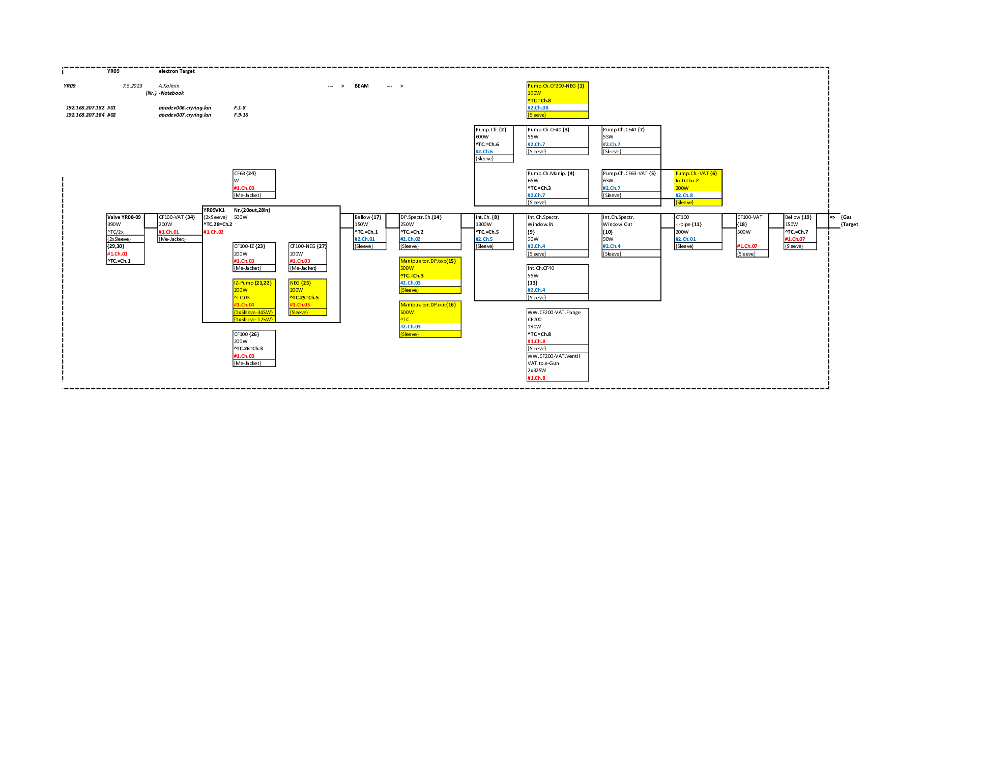
JM | Updated thermocouple positions and heater channel layouts |
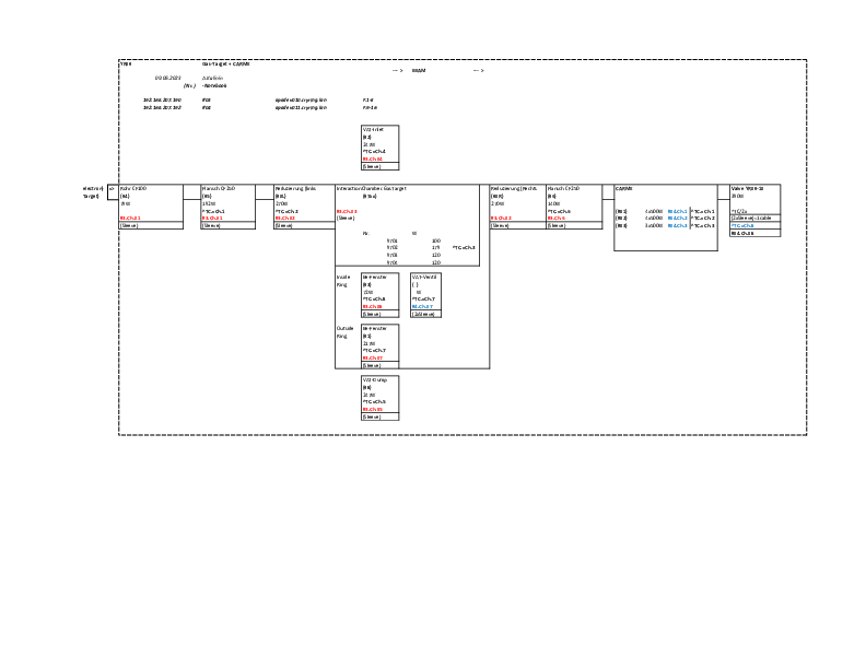
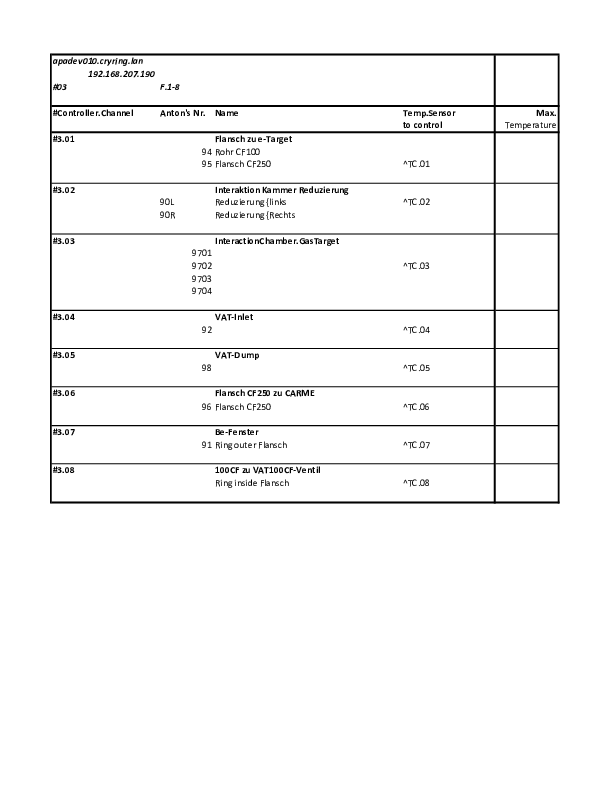
Heater channel layouts for the interaction chamber and carme in attached documents.
Updated thermocouple positions; (front section is closest to gas-target, rear section is moving detector end)
- 1-1 Internal TC 1
- 1-2 Internal TC 2
- 1-3 Internal TC 3
- 1-4 CARME - top of the front section
- 1-5 CARME - bottom of the front section
- 1-6 CARME - top of the mid section
- 1-7 CARME - middle of the mid section
- 1-8 CARME - bottom of the mid section
- 2-1 Float - bottom of mid section
- 2-2 CARME - middle of rear section
- 2-3 Float - middle of the front section
- 2-4 CARME - bottom VAT valve
- 2-5 Float - middle of the rear section
- 2-6 CARME - Top elbow
- 2-7 Float - top of the mid section
- 2-8 CARME - rear beam pipe
Thermocouple posiitons have been updated in the monitoring code, including the averages for the CARME chamber. |
| Attachment 1: Cryring-YR09-CARME-Layout.pdf
|
|
| Attachment 2: Cryring-YR09-CARME-Layout2.pdf
|
|
| Attachment 3: Cryring-YR09-CARME-Layout3.pdf
|

|
| Attachment 4: Cryring-YR09-eTarget-Layout1.pdf
|
|
| Attachment 5: Cryring-YR09-eTarget-Layout2.pdf
|

|
| Attachment 6: Cryring-YR09-eTarget-Layout3.pdf
|

|
|
289
|
Sat Feb 26 23:20:13 2022 |
David, Pierre-Michell | Update status |
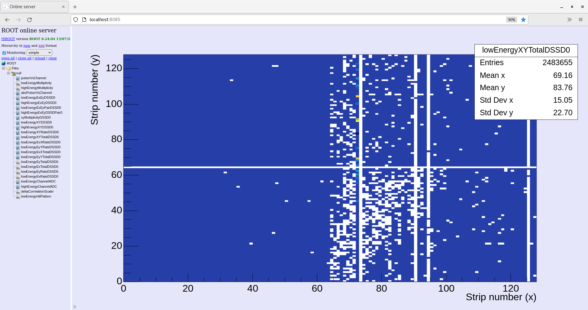
In this last hour we have been playing with the cryostat temperature as dictated by Nikos, in order to have the target working properly. For this, we have increased from 80K to 140K the cryostat temperature then we saw again target until we didn't. Then we went down again to 80K. After a few minutes, with a really nice target again was gone, so we increased the temperature to 120K at 00:19. At 00:27 decrease from 120K to 80K.
Ring current 8e7 particles/s
Merger, Tape server (WS3): 1580 kB/s writing ok
Leakage current (WS4): 3.27 uA
DAQ (WS2): temperature checked, clock status: ok, adc calibration: ok, white rabbit check: failed
Online monitoring (WS 5): done |
| Attachment 1: 2022-02-27_00-26-44xytotal.png
|
|
| Attachment 2: 2022-02-27_00-26-22exrate.png
|

|
| Attachment 3: 2022-02-27_00-25-29extotal.png
|

|
| Attachment 4: 2022-02-27_00-25-07temp.png
|

|
| Attachment 5: 2022-02-27_00-24-47goodevents.png
|

|
| Attachment 6: 2022-02-27_00-23-42current.png
|

|
| Attachment 7: 2022-02-27_00-31-26.png
|

|
|
60
|
Tue Sep 7 11:37:05 2021 |
CB RSS + OG | Update on strain relief screw issues |
Tested every strain relief. M3 screws get stuck at different points in each hole. Only one good hole out of 16
(2x8).
They were tested in Edinburgh - unclear if this is a result of baking at high temperatures, or bad screws, or
something else.

Easiest solution may be to re-machine holes and clean the connectors here in GSI.
Now investigating options. |
|
440
|
Sat Sep 2 10:04:55 2023 |
CB | Turbo GV closed |
Found CARME in XHV at 1.1E-11 mbar. Chamber temperature around 30C cooling slowly.
Closed GV to top turbo. Pressure goes up but appears to recover around 2.5E-11 mbar, on line with several previous observations that sectioning off the turbo results in a higher reading in the IE514.
Left turbo on. Remember to not turn it off when removing the tent. |
|
370
|
Tue Aug 9 13:44:16 2022 |
TD, JM | Tuesday 9 August |
14.00 CARME vacuum c. 1.8e-10 mbar - see attachment 1

open water inlet/outlet taps

NIM bin (MACBs, Ortec 480 Pulser, CAEN N1419ET) switched ON

USB-controlled ac mains relay switched ON - water & interlock LEDs active

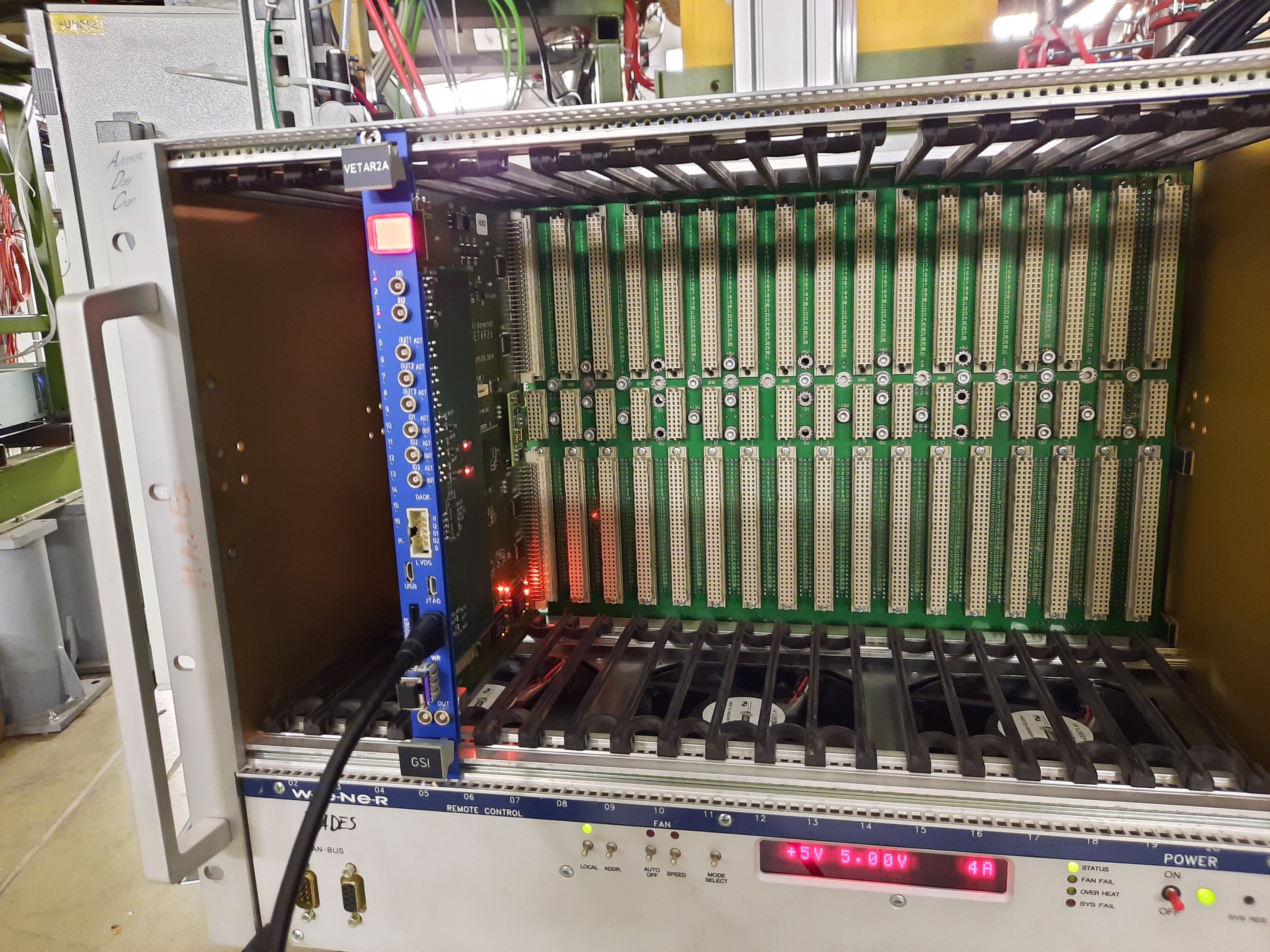
Require VETAR2 (previous returned to Nik Kurz) and network switch (currently with AIDA@DESPEC)

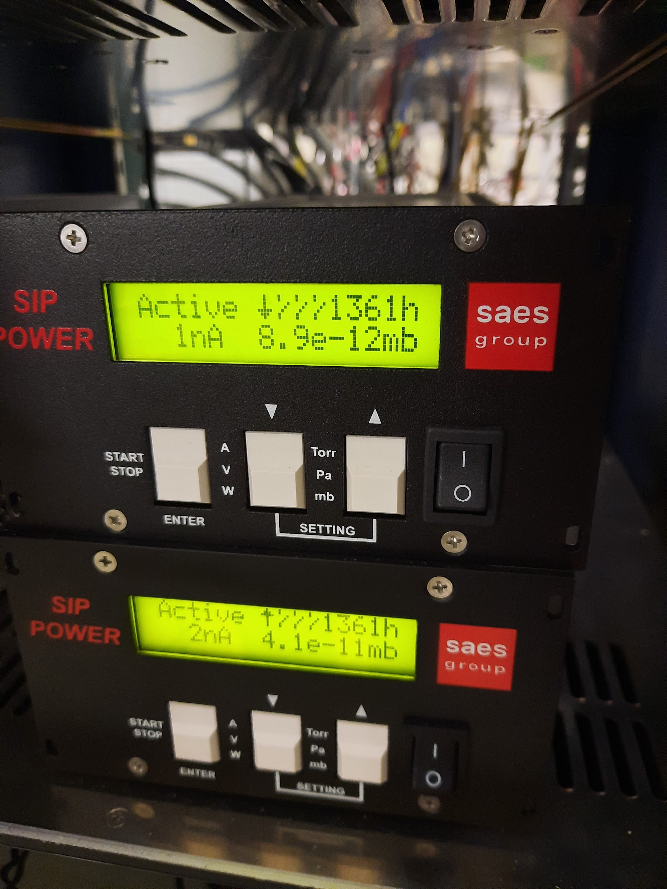
Turbo pump ON - normal operation

Ion pumps ON - normal operation

16.30 ML informs us that ambient temperature of CRYRING cave has been increased from c. 16 deg C to c. 21 deg C and that this is likely the cause of the change in vacuum
pressure in YR09 and the rest of the storage ring.

obtained VETAR2 and crate

anydesk restarted |
| Attachment 1: Capture_1.PNG
|

|
| Attachment 2: 20220809_163450.jpg
|
|
| Attachment 3: 20220809_135840.jpg
|

|
| Attachment 4: 20220809_135833.jpg
|
|
| Attachment 5: 20220809_135801.jpg
|

|
|
668
|
Tue Apr 8 10:46:13 2025 |
TD | Tuesday 8 April |
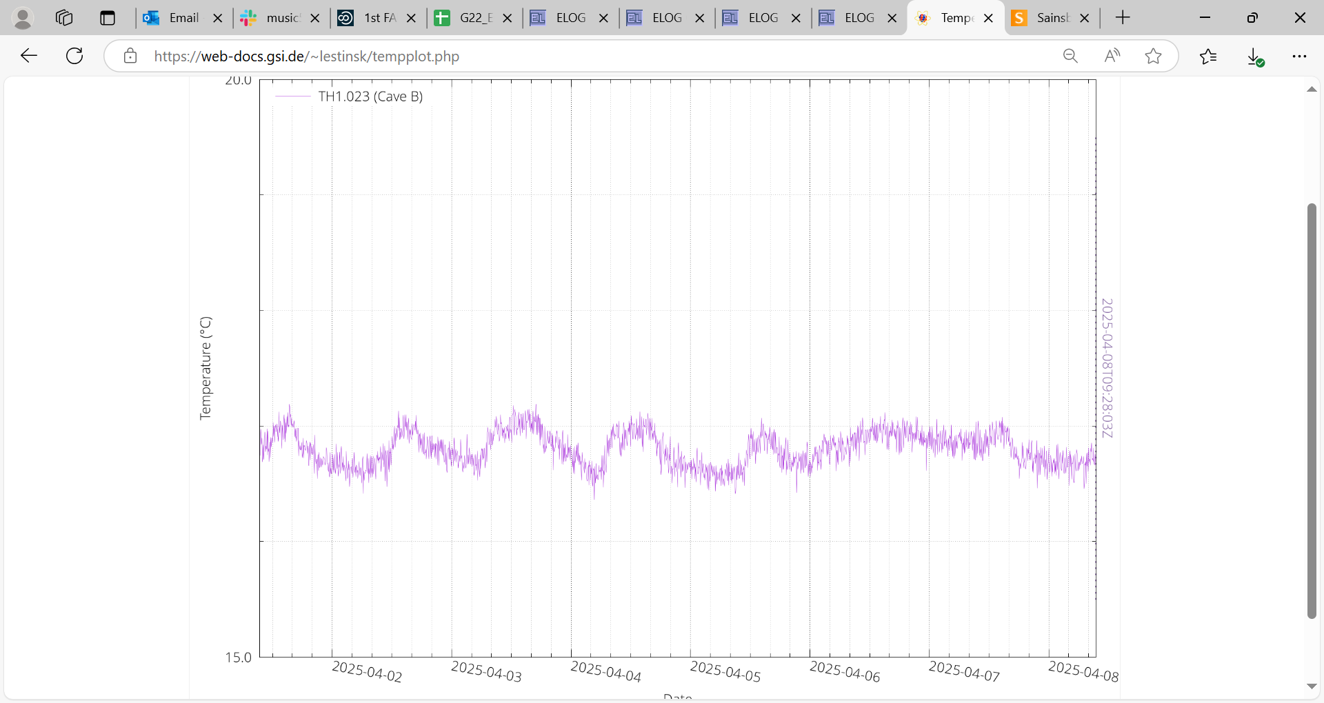
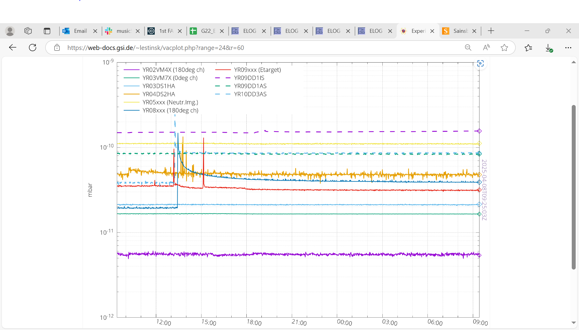
11.30 CRYRING vacuum and temperature - attachments 1-2

      DSSSD bias & leakage current - attachment 3
       c. 1uA reduction in DSSSD#1 and DSSSD#2 leakage currents cf. yesterday but remain high cf.June 2024

      FEE64 temps OK - attachment 4

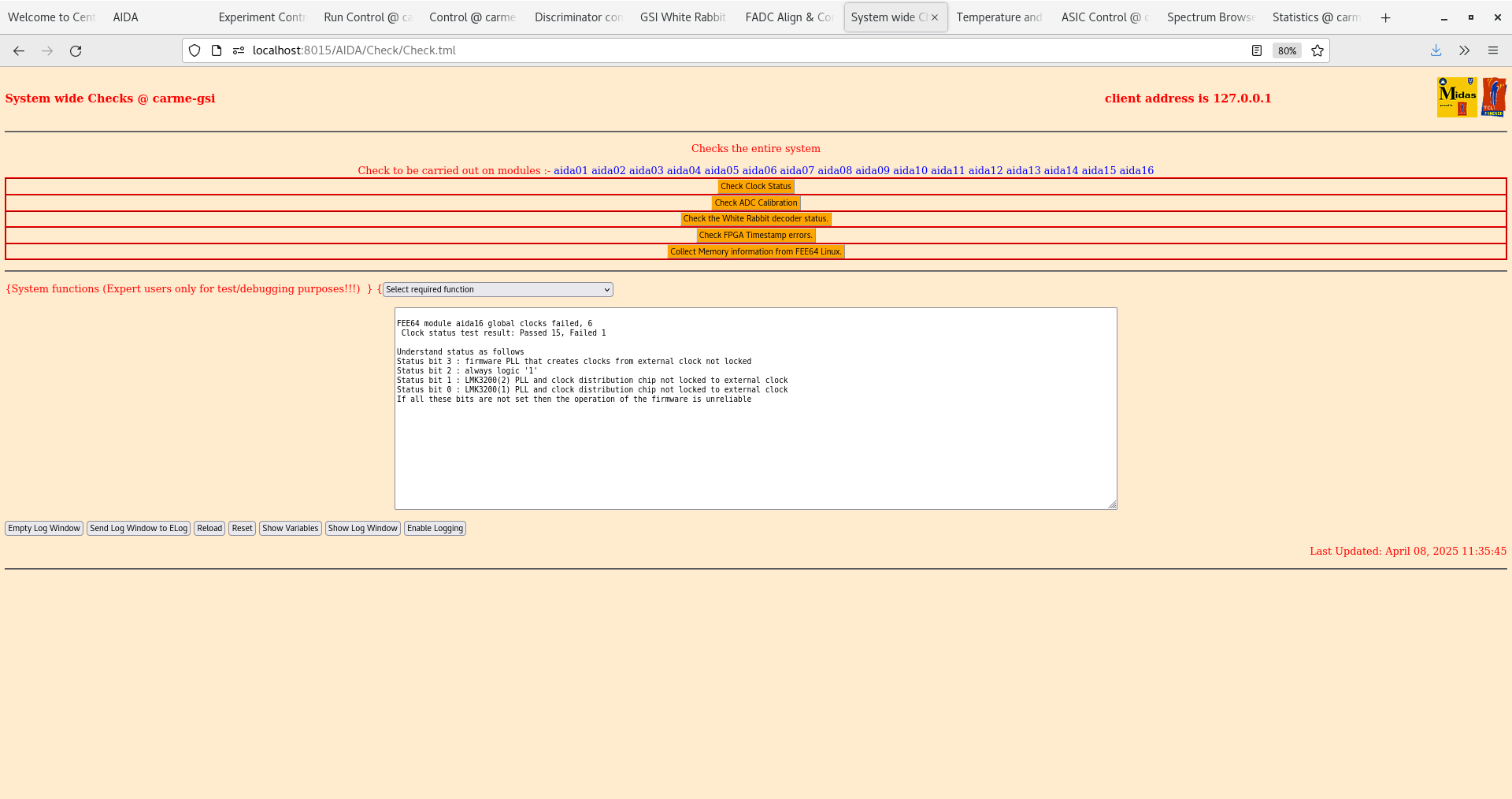
      System wide checks - clock fail aida16 - attachments 5-6
       aida16 global clock status 0x6 - non-critical failure, often resolved by a power cycle.

      ADC data item stats - attachment 7
       DSSSD #3 n+n Ohmic side FEE64 rates return to c. normal cf. yesterday


      per FEE64 Rate spectra - attachment 8

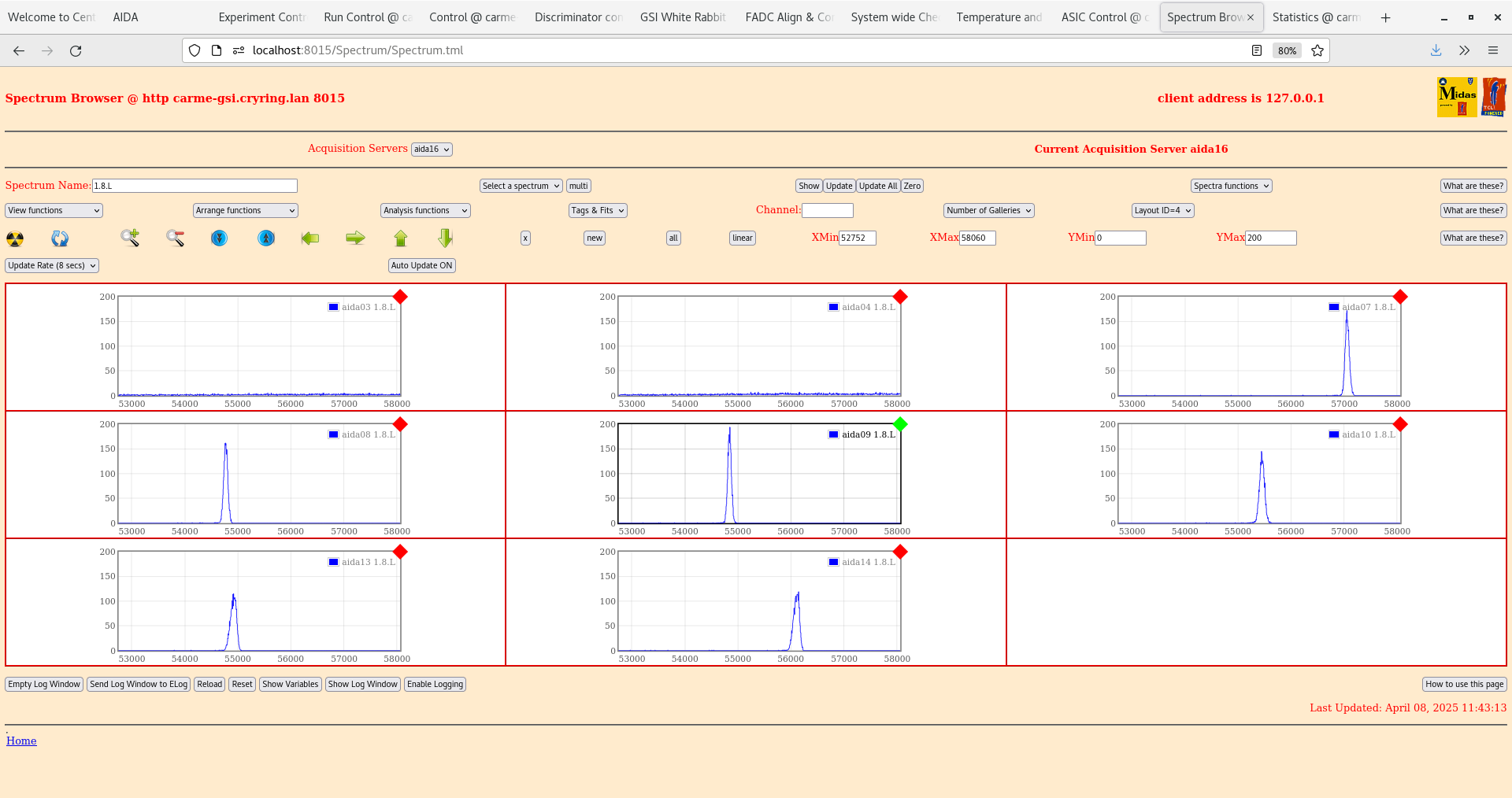
      per FEE64 1.8.L spectra - attachments 9-10
       pulser peak width aida11 55 ch FWHM, aida09 75 ch FWHM
       only DSSSD #3 aida11/aida12 have expected peak widths

      per FEE64 1.8.W spectra - 20us FSR - attachments 11-13

      WR timestamps OK - attachment 14

17.29 DSSSD bias & leakage current - attachment 15

      FEE64 temps OK - attachment 16

      WR timestamps OK - attachment 17

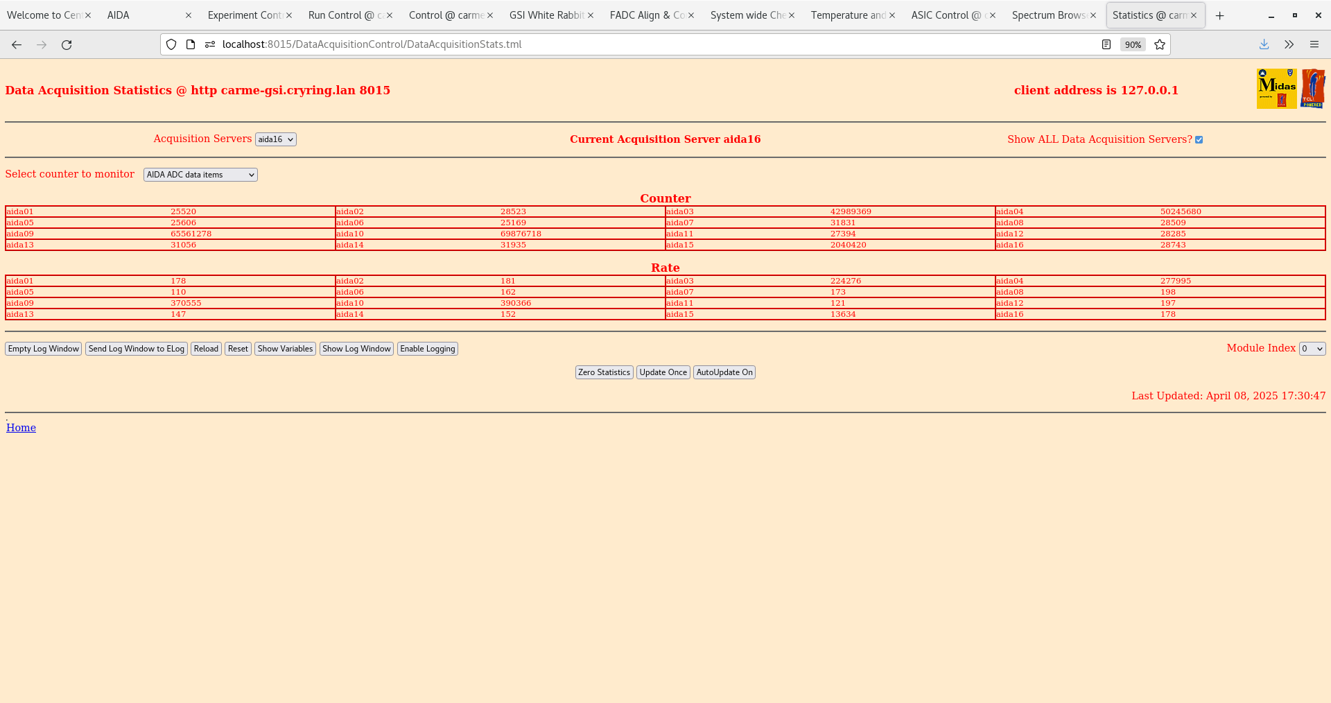
      ADC data item stats - attachment 18

      per FEE64 Rate spectra - attachment 19

17.35 All histograms & stats zero'd
      Start run
      Data file APR25/R5
      alpha background

      EG&G Ortec 448 Pulser
       amplituide 90,000
       normalise 5.00
       x5 attenuator IN
       INT OSC
       frequency 2Hz
       t_r 100ns
       tau_d 50us (1000us setting does not work)
       polarity +

       ASIC settings 2025Apr08-13.45.30
        slow comparator 0x64
        aida03, aida04, aida09, aida10 LEC/EC range setting -> MEC

      per FEE64 Rate spectra - attachment 20

      Merger & Tape Server - attachment 21-22

20.41 DAQ continues
      Data file APR25/R5_7

      DSSSD bias & leakage current - attachment 23

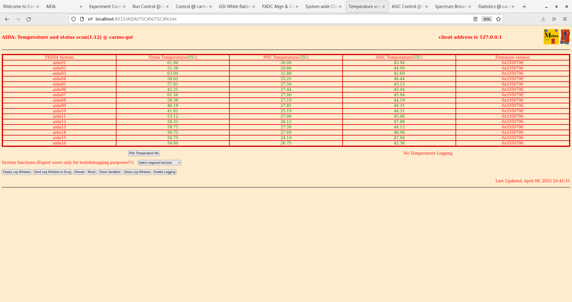
      FEE64 temps OK - attachment 24

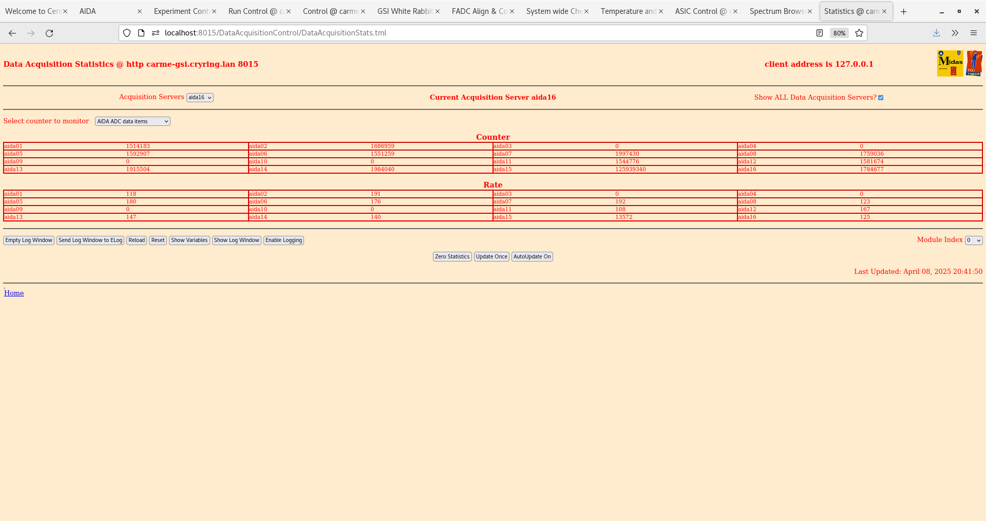
      ADC data item stats - attachment 25

      Merger & Tape Server - attachment 26-27

      per FEE64 Rate spectra - attachment 19
|
| Attachment 1: Capture_2.PNG
|
|
| Attachment 2: Capture.PNG
|
|
| Attachment 3: Screenshot_from_2025-04-08_11-29-48.png
|

|
| Attachment 4: Screenshot_from_2025-04-08_11-30-14.png
|

|
| Attachment 5: Screenshot_from_2025-04-08_11-38-06.png
|
|
| Attachment 6: Screenshot_from_2025-04-08_11-38-29.png
|

|
| Attachment 7: Screenshot_from_2025-04-08_11-38-46.png
|

|
| Attachment 8: Screenshot_from_2025-04-08_11-39-39.png
|

|
| Attachment 9: Screenshot_from_2025-04-08_11-41-09.png
|

|
| Attachment 10: Screenshot_from_2025-04-08_11-43-20.png
|
|
| Attachment 11: Screenshot_from_2025-04-08_11-43-56.png
|

|
| Attachment 12: Screenshot_from_2025-04-08_11-44-24.png
|

|
| Attachment 13: Screenshot_from_2025-04-08_11-45-11.png
|

|
| Attachment 14: Screenshot_from_2025-04-08_13-36-00.png
|

|
| Attachment 15: Screenshot_from_2025-04-08_17-29-11.png
|

|
| Attachment 16: Screenshot_from_2025-04-08_17-29-35.png
|

|
| Attachment 17: Screenshot_from_2025-04-08_17-30-30.png
|

|
| Attachment 18: Screenshot_from_2025-04-08_17-30-56.png
|
|
| Attachment 19: Screenshot_from_2025-04-08_17-28-57.png
|

|
| Attachment 20: Screenshot_from_2025-04-08_17-37-47.png
|

|
| Attachment 21: Screenshot_from_2025-04-08_17-35-42.png
|

|
| Attachment 22: Screenshot_from_2025-04-08_17-35-54.png
|

|
| Attachment 23: Screenshot_from_2025-04-08_20-40-46.png
|

|
| Attachment 24: Screenshot_from_2025-04-08_20-41-39.png
|
|
| Attachment 25: Screenshot_from_2025-04-08_20-41-56.png
|
|
| Attachment 26: Screenshot_from_2025-04-08_20-42-29.png
|

|
| Attachment 27: Screenshot_from_2025-04-08_20-42-48.png
|

|
|
481
|
Tue Jan 30 09:14:50 2024 |
JM, TD | Tuesday 30 January |
09.00 CARME IE514 5.1e-11mbar

09.15 IE514 not working - one of cables disconnected?

      DSSSD #1 bias cable changed from SHV - Lemo 00.250 to SHV - 2x Lemo 00.250

      DSSSD #1 & #2 LK1 removed from n+n Ohmic side bias FEE64s

      aida11 HDMI cabling re-seated at MACB

10.26 DSSSD bias OK - attachment 1
      Ambient temperature +16.2 deg C

10.30 ADC data item stats OK - attachment 2
      aida06 & aida15 > 100k, all others c. 3k consistent with 50Hz pulser

10.34 per FEE64 Rate spectra - attachment 3
       OK except for known issues aida05, aida07 and aida16 - all others OK

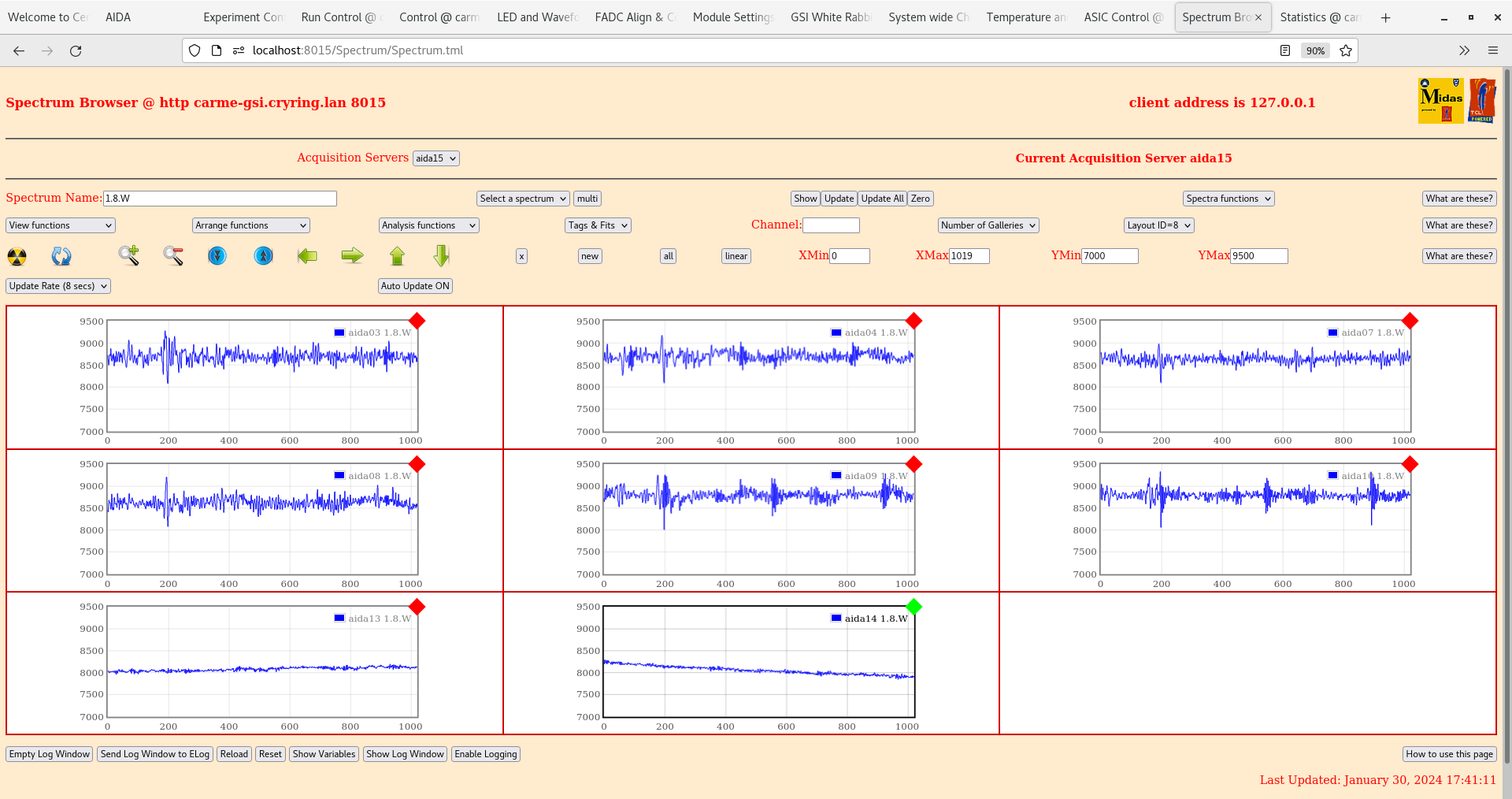
      per p+n FEE64s 1.8.L spectra - attachment 4
       pulser peak width 52 ch FWHM aida11- double peaking DSSSD #1 & #2

      per n+n FEE64s 1.8.L spectra - attachment 7
       pulser peak width 77 ch FWHM aida04 - more uniform noise across all DSSSDs

10.42 per FEE64 1.8.W spectra - 20us FSR - attachments 5-6

11:00 LK2 removed from aida01-04. Configuration for all adaptor cards/FEE modules is now the same. No other change to the setup.

12:00 FEEs power on, bias to 150 V. No change in bias observed.

12.02 ADC data item stats OK
      aida06 & aida15 > 100k, all others c. 3k consistent with 50Hz pulser

12.07 per FEE64 Rate spectra
       OK except for known issues aida05, aida07 and aida16 - all others OK

12:09  per p+n FEE64s 1.8.L spectra
       We now observe a large peak around chn 30,000 on all FEEs. Perhaps an effect of some change in the ring?
       pulser peak width 53 ch FWHM aida11- still observe double peaking DSSSD #1 & #2

      per n+n FEE64s 1.8.L spectra
      Lots of events at ~chn 65,000 - double peaking now observed on aida03 and aida04
      pulser peak width 93 ch FWHM aida14

12.20 per FEE64 1.8.W spectra - 20us FSR

      Perhaps bias was off while acquiring and spectra was not cleared properly. Re-do tests

13:40 ADC data item stats OK - attachment 7
      aida06 & aida15 > 100k, all others c. 3k consistent with 50Hz pulser

       per FEE64 Rate spectra - attachment 8
       OK except for known issues aida05, aida07 and aida16 - all others OK

      per p+n FEE64s 1.8.L spectra - attachment 9
       pulser peak width 55 ch FWHM aida11- double peaking DSSSD #1 & #2

      per n+n FEE64s 1.8.L spectra - attachment 10
       pulser peak width 65 ch FWHM aida14 - more uniform noise across all DSSSDs

       per FEE64 1.8.W spectra - 20us FSR - attachments 11-12

      With help from NH updated firmware on all MACB modules to version 4/20 - see https://elog.ph.ed.ac.uk/CARME/482

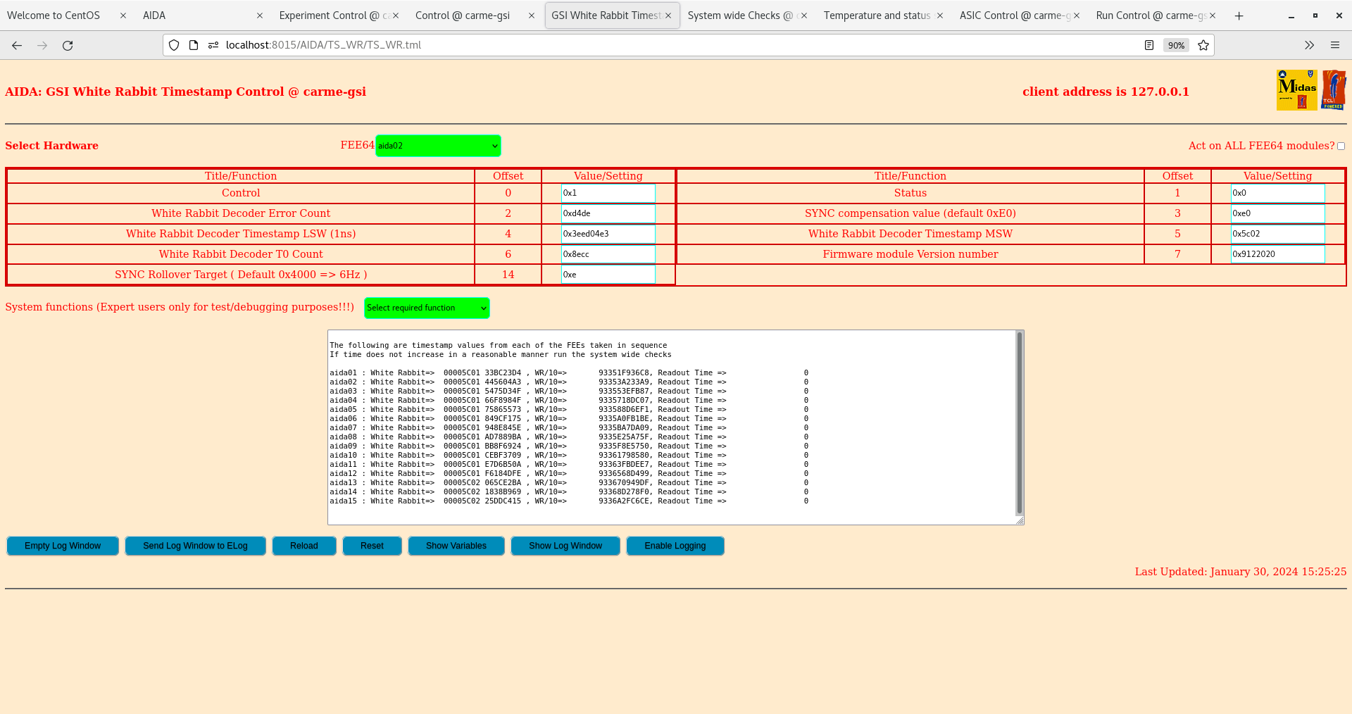
      Timestamps for all FEE modules now correct - attachment 13

      MAC address of aida07 was found to be 41-b4-16 not 41-d4-16 as was labelled on the FEE module
       re-labelled FEE64
       dhcpd.conf and MIDAS startup.tcl updated, dhcpd and MIDAS 8015 server restarted - aida07 is now working OK

      CAEN N1419ET internal jumper fitted - outputs are no longer floating

15:20 ADC data item stats OK
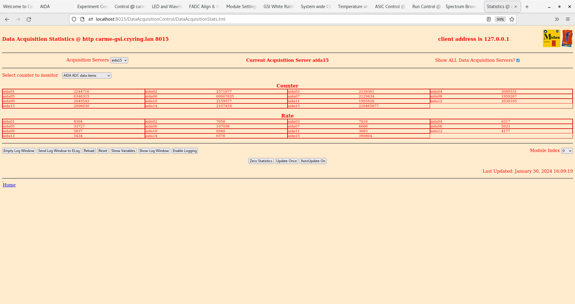
      aida06 & aida15 > 100k, all others c. 3k consistent with 50Hz pulser - attachment 14

       per FEE64 Rate spectra
       OK except for known issues aida05, and aida16 - all others OK  - attachment 15

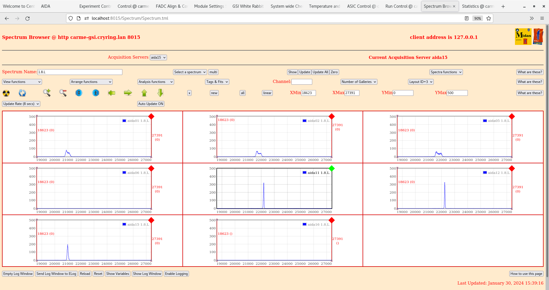
      per p+n FEE64s 1.8.L spectra -
       pulser peak width 50 ch FWHM aida11- double peaking DSSSD #1 & #2 - attachment 16

      per n+n FEE64s 1.8.L spectra
       pulser peak width 67 ch FWHM aida14 - more uniform noise across all DSSSDs

       per FEE64 1.8.W spectra - 20us FSR - aida14 missing from waveforms - attachments 17,18

   Swapped the test inputs so that +ve is now from the inverter and -ve direct from pulser.  - attachments 19,20. Observed reduced noise for when plugged directly into the pulser than when connected from the inverter.


   Lowered threshold from 0x64 (1 MeV) to 0x20 (320 keV) - attachment 21, 22 - Observed increase in rates, in particular for the DSSD #1,2 pn side. Conclusion -> increased pulser width for DSSD #1,2 is real and not from the pulser


   aida01 lemo to water pipe (chamber ground) connection installed

   ADC data item stats OK
      aida06 & aida15 > 100k, all others c. 3k consistent with 50Hz pulser

       per FEE64 Rate spectra
       OK except for known issues aida16 - all others OK

      per p+n FEE64s 1.8.L spectra -
       pulser peak width 48 ch FWHM aida11- double peaking DSSSD #1 & #2 - attachment 23

      per n+n FEE64s 1.8.L spectra
       pulser peak width 67 ch FWHM aida14 - attachment 24

       per FEE64 1.8.W spectra - 20us FSR - slightly reduced 100 kHz on pn waveforms - attachments 25,26

   Disconnected aida06 and replaced with the spare FEE module (mac address: 42:0d:16). Power cycled and updated config files.

   ADC data item stats OK
      aida15 > 100k, all others including aida06 c. 3k consistent with 50Hz pulser - attachment 27

       per FEE64 Rate spectra
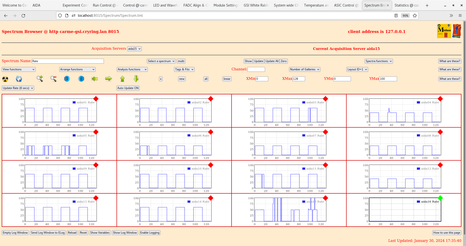
       OK except for known issues aida16 - all others OK - attachment 28

      per p+n FEE64s 1.8.L spectra -
       pulser peak width 48 ch FWHM aida11- no longer observe double peaking DSSSD #1 & #2 but the pulser peaks are still broader compared to DSSD #3,4 - attachment 29

      per n+n FEE64s 1.8.L spectra
       pulser peak width 55 ch FWHM aida14 - attachment 30

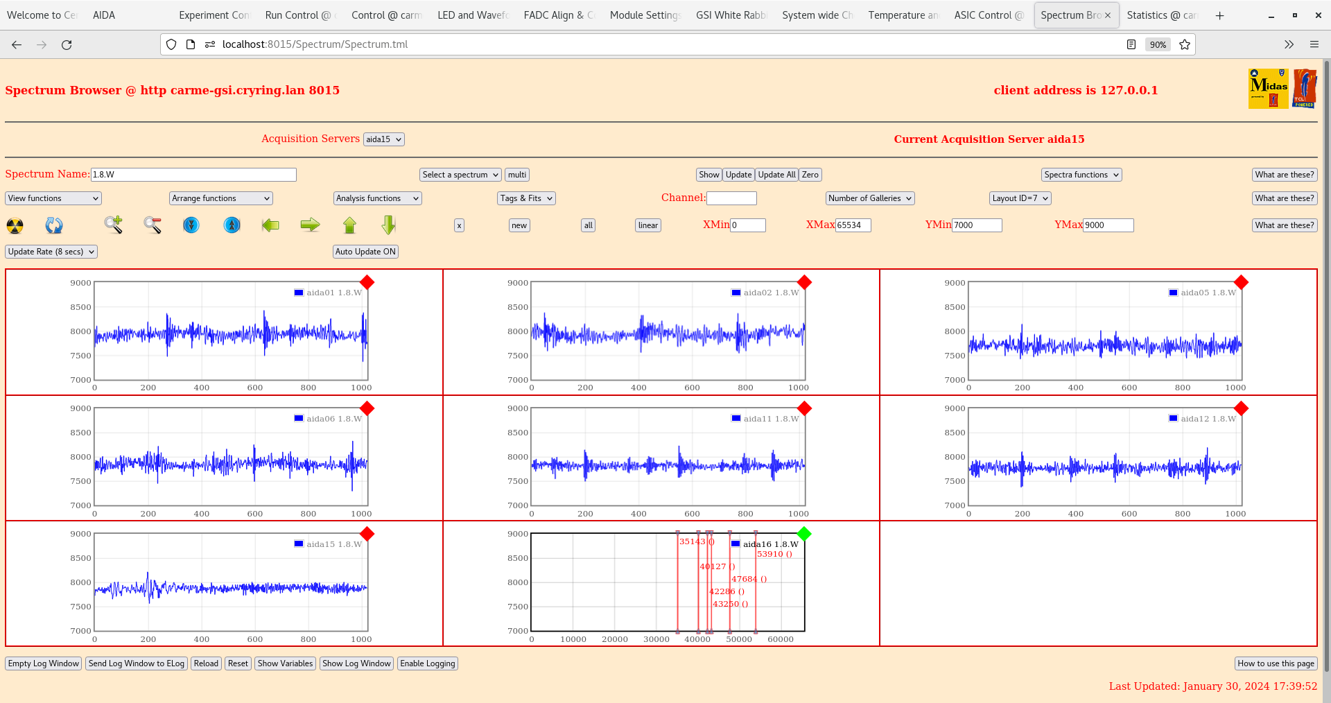
       per FEE64 1.8.W spectra - 20us FSR - greatly reduced 100 kHz on pn waveforms, dodgy FEE previously aida06 must@ve had some impact on DSSD#1,2 - attachments 31,32
|
| Attachment 1: Screenshot_from_2024-01-30_10-32-41.png
|

|
| Attachment 2: Screenshot_from_2024-01-30_10-36-20.png
|

|
| Attachment 3: Screenshot_from_2024-01-30_10-40-21.png
|

|
| Attachment 4: Screenshot_from_2024-01-30_10-46-39.png
|

|
| Attachment 5: Screenshot_from_2024-01-30_10-48-17.png
|

|
| Attachment 6: Screenshot_from_2024-01-30_10-48-59.png
|

|
| Attachment 7: Screenshot_from_2024-01-30_13-44-18.png
|

|
| Attachment 8: Screenshot_from_2024-01-30_13-45-18.png
|

|
| Attachment 9: Screenshot_from_2024-01-30_13-46-20.png
|

|
| Attachment 10: Screenshot_from_2024-01-30_13-47-54.png
|

|
| Attachment 11: Screenshot_from_2024-01-30_13-52-14.png
|

|
| Attachment 12: Screenshot_from_2024-01-30_13-53-09.png
|

|
| Attachment 13: Screenshot_from_2024-01-30_15-25-38.png
|
|
| Attachment 14: Screenshot_from_2024-01-30_15-33-37.png
|

|
| Attachment 15: Screenshot_from_2024-01-30_15-38-08.png
|

|
| Attachment 16: Screenshot_from_2024-01-30_15-39-28.png
|
|
| Attachment 17: Screenshot_from_2024-01-30_15-43-00.png
|

|
| Attachment 18: Screenshot_from_2024-01-30_15-46-32.png
|

|
| Attachment 19: Screenshot_from_2024-01-30_16-01-08.png
|

|
| Attachment 20: Screenshot_from_2024-01-30_16-03-27.png
|

|
| Attachment 21: Screenshot_from_2024-01-30_16-08-50.png
|

|
| Attachment 22: Screenshot_from_2024-01-30_16-09-27.png
|
|
| Attachment 23: Screenshot_from_2024-01-30_16-48-21.png
|

|
| Attachment 24: Screenshot_from_2024-01-30_16-49-38.png
|

|
| Attachment 25: Screenshot_from_2024-01-30_16-50-41.png
|

|
| Attachment 26: Screenshot_from_2024-01-30_16-51-51.png
|

|
| Attachment 27: Screenshot_from_2024-01-30_17-35-01.png
|

|
| Attachment 28: Screenshot_from_2024-01-30_17-36-01.png
|
|
| Attachment 29: Screenshot_from_2024-01-30_17-36-57.png
|

|
| Attachment 30: Screenshot_from_2024-01-30_17-39-02.png
|

|
| Attachment 31: Screenshot_from_2024-01-30_17-40-05.png
|
|
| Attachment 32: Screenshot_from_2024-01-30_17-41-19.png
|
|
|
452
|
Tue Oct 3 08:48:36 2023 |
TD | Tuesday 3 October |
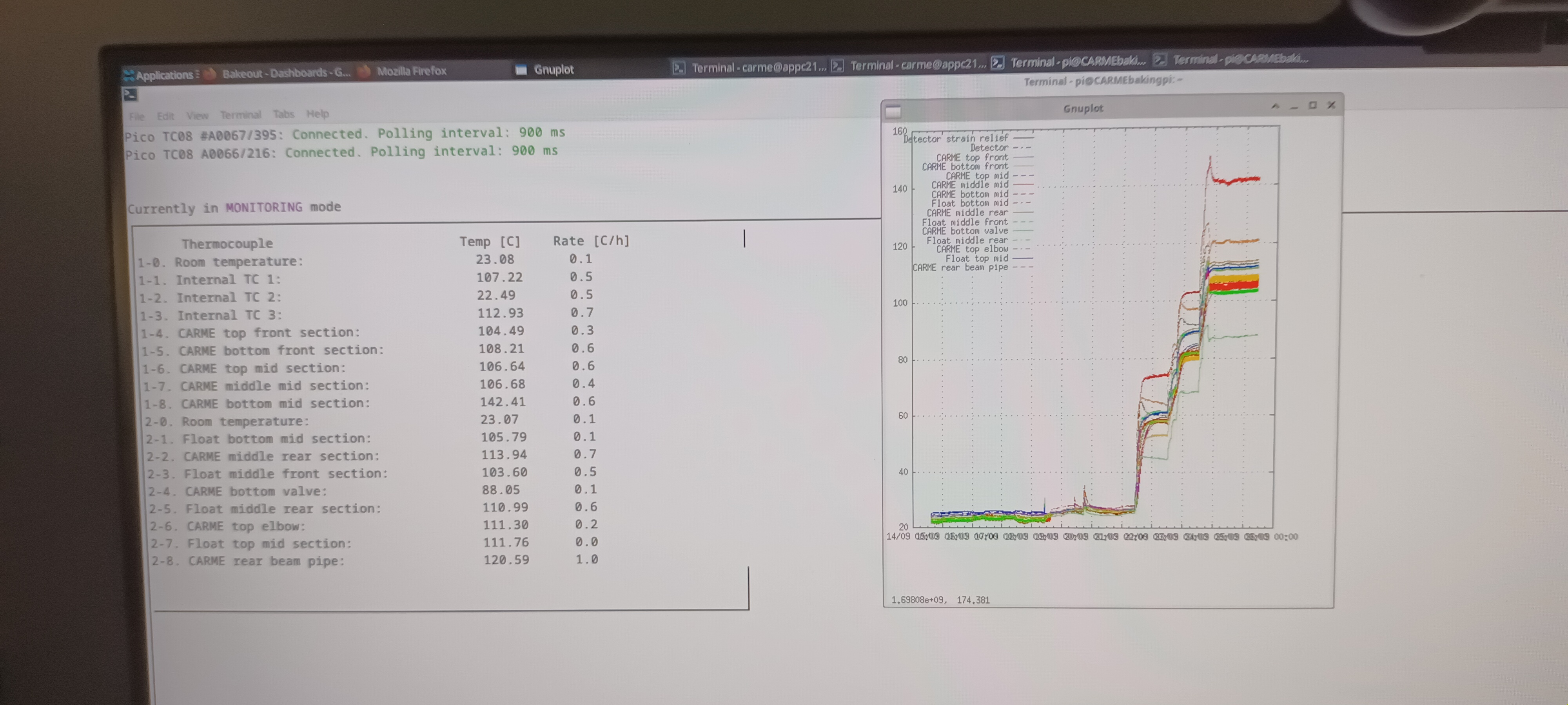
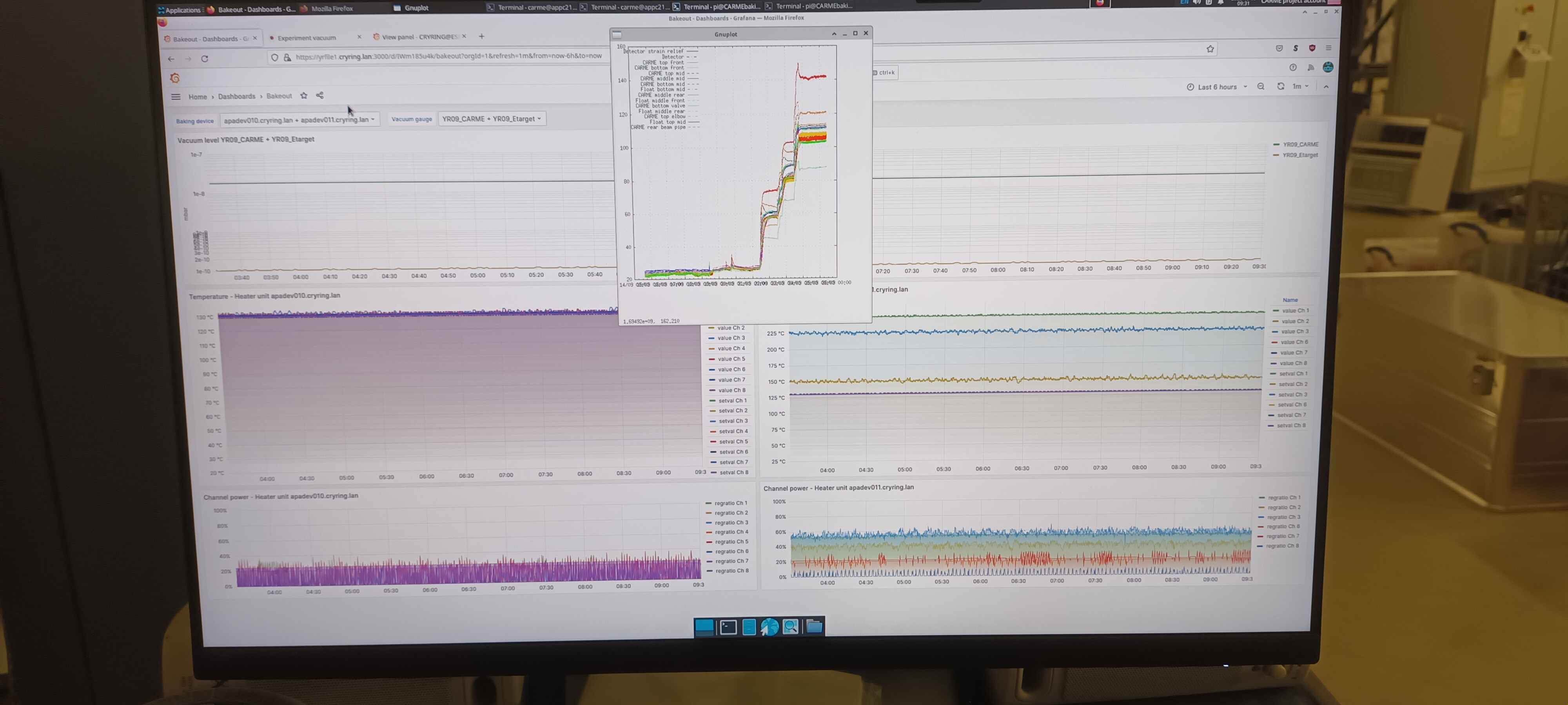
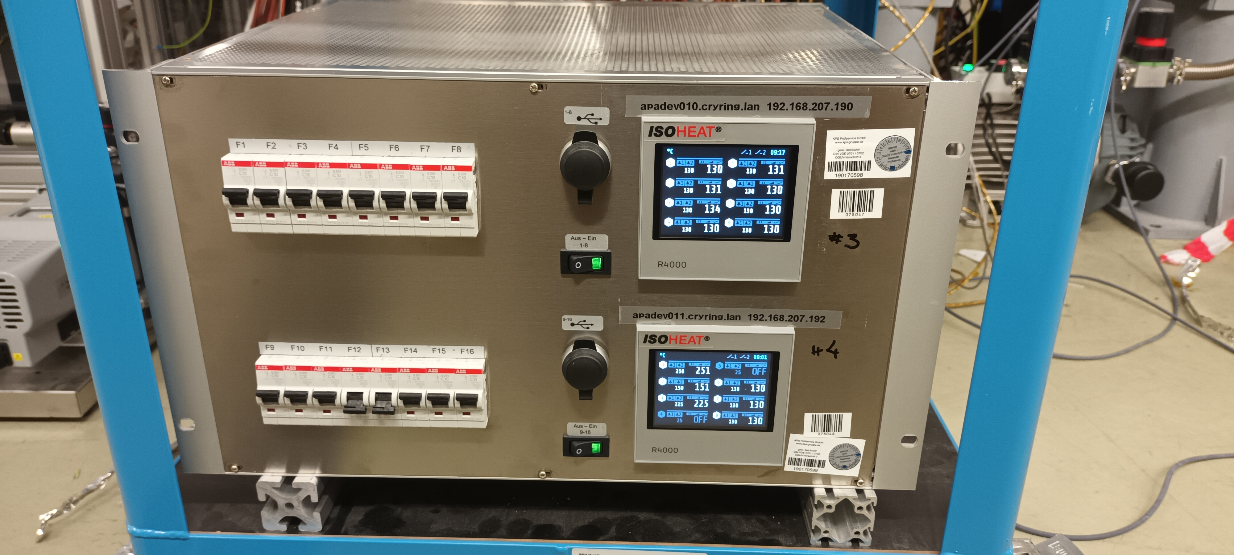
09.40 CARME IE514 1.79e-8 mbar, ambient temperature 20.7 deg C

      CARME bakeout monitor, ELOTECH R4000 temperature controller front panel and Grafana bakeout dashboard- attachments 1-3

No change to ELOTECH R4000 set point |
| Attachment 1: 1000007432.jpg
|
|
| Attachment 2: 1000007431.jpg
|
|
| Attachment 3: 1000007434.jpg
|
|
|
381
|
Tue Nov 29 14:37:56 2022 |
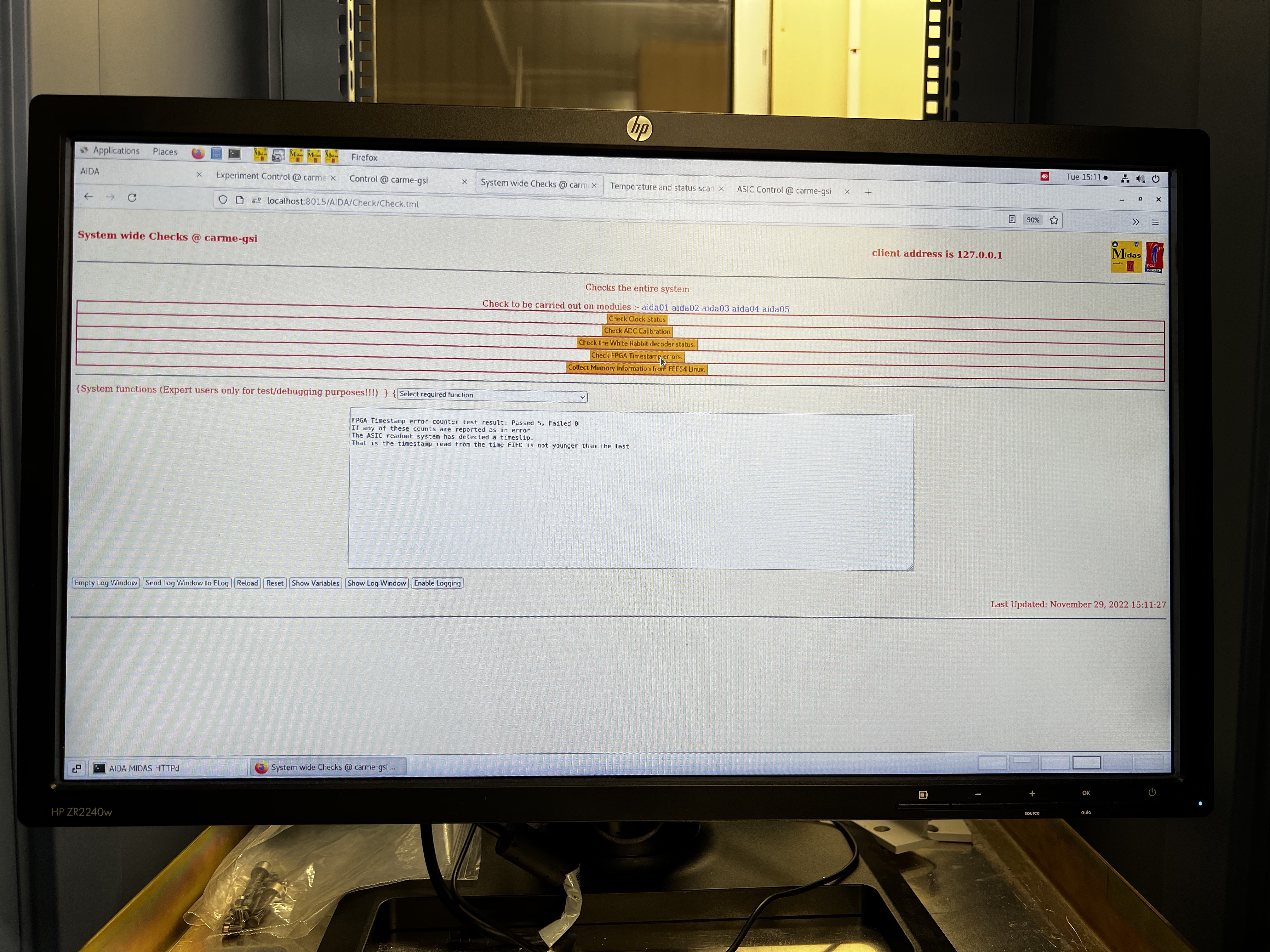
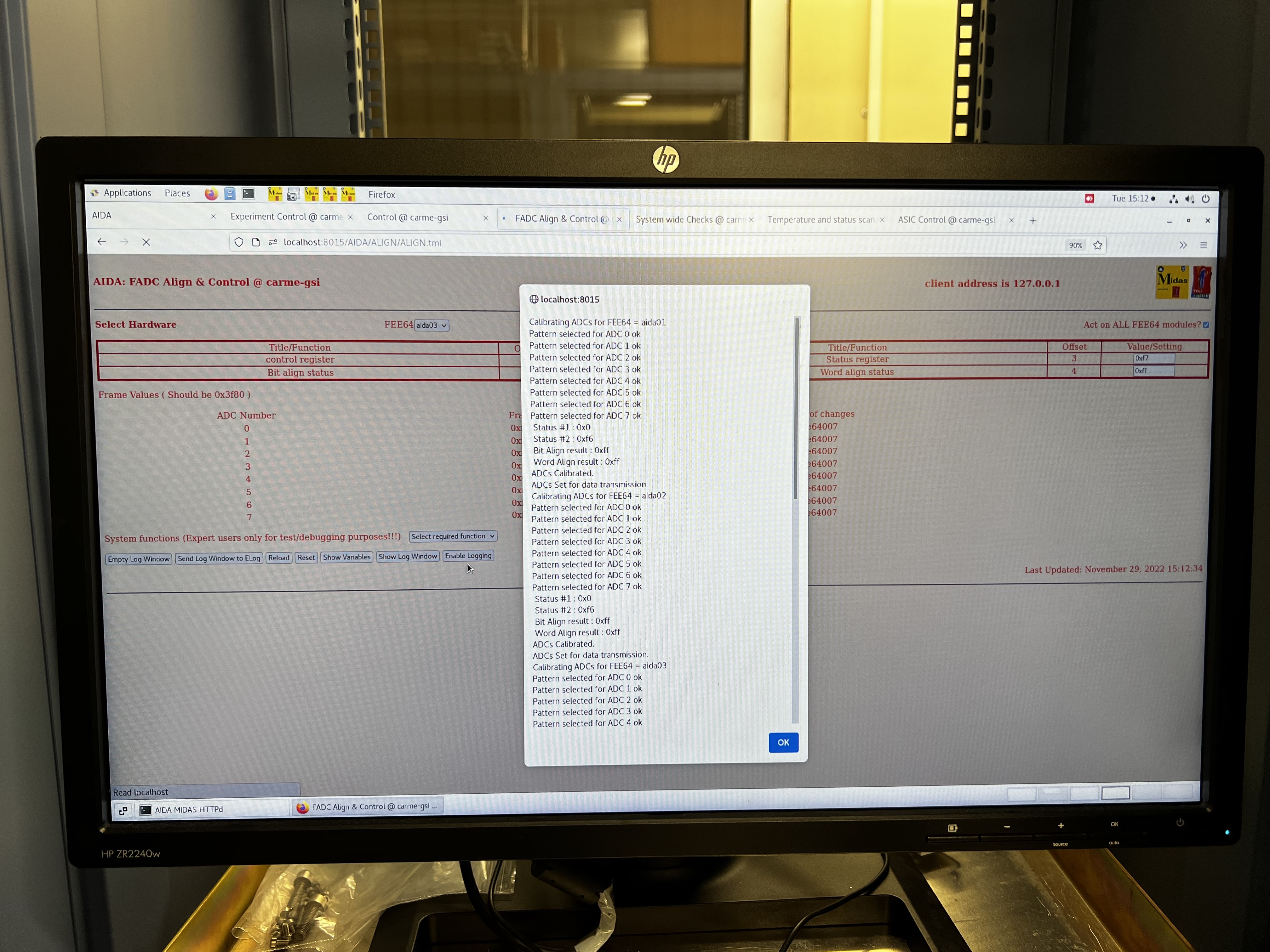
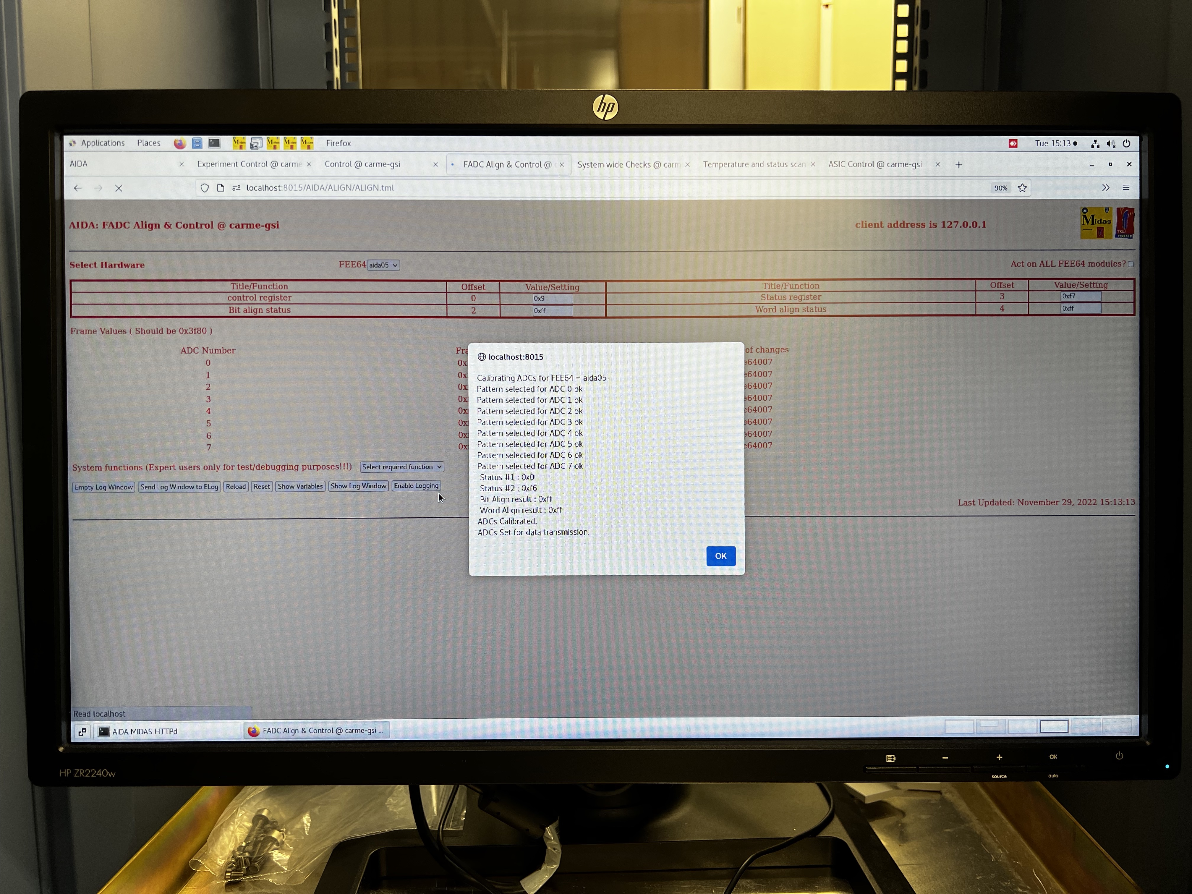
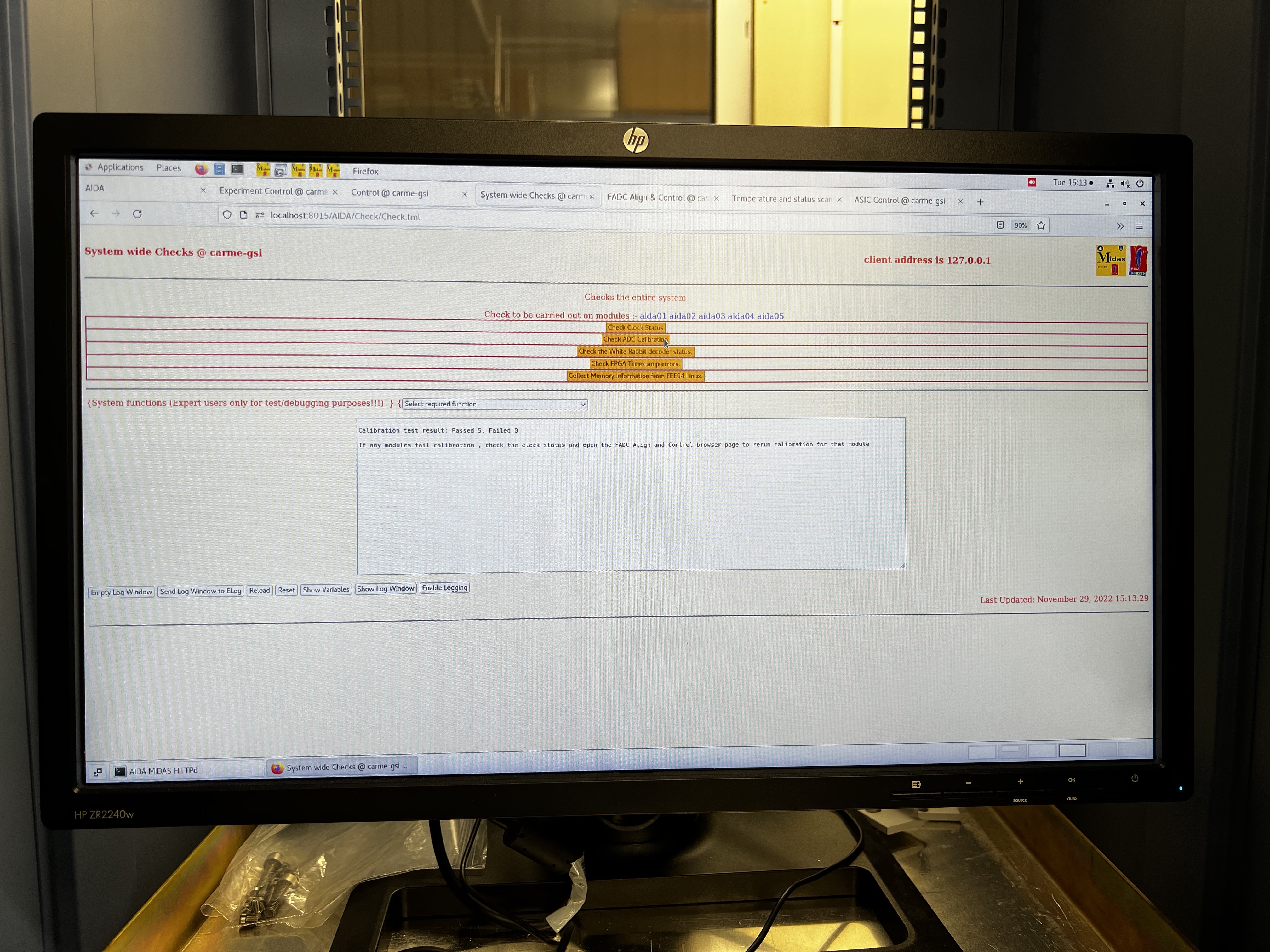
AR TD | Tuesday 29 November |
16:20
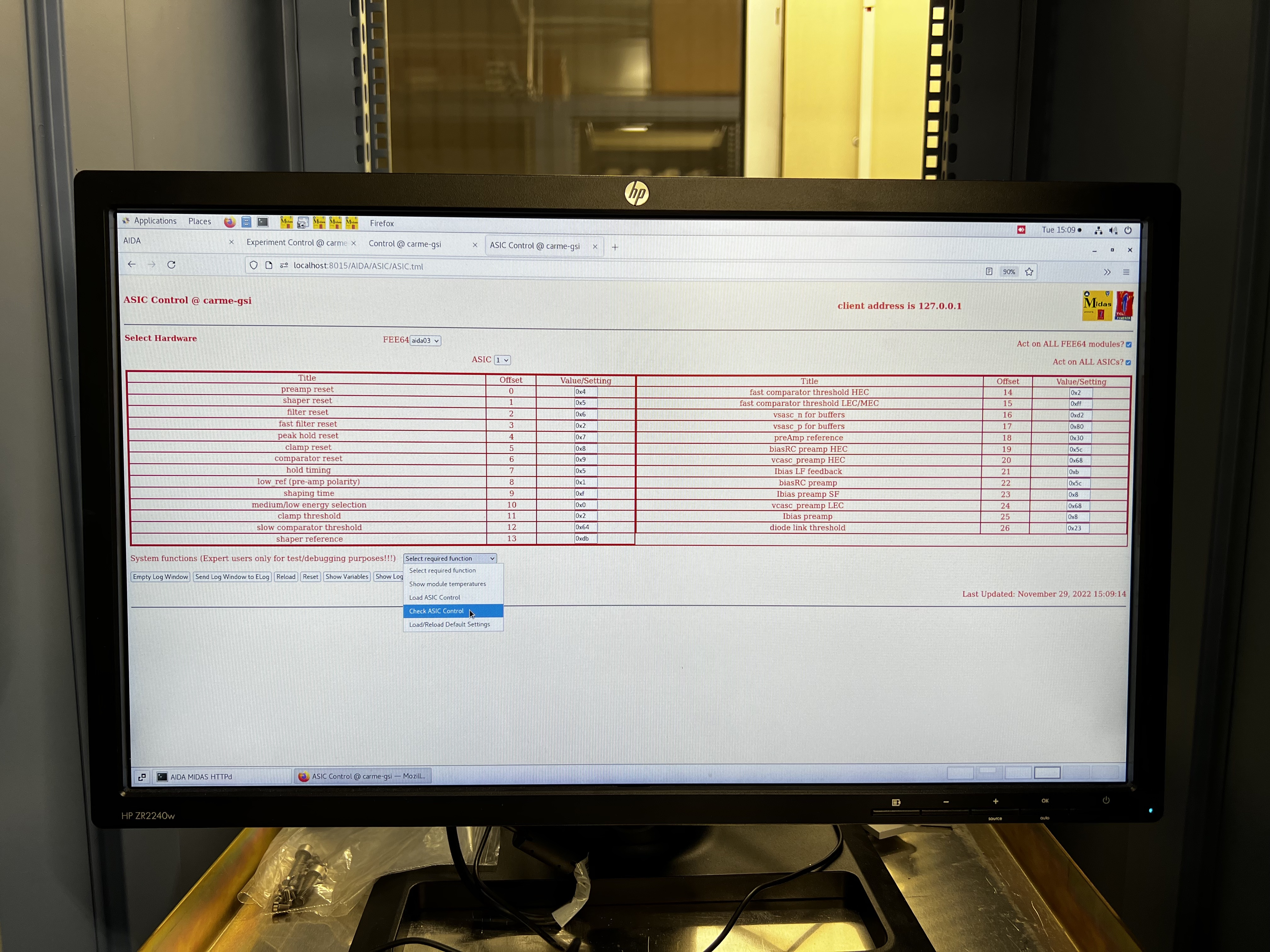
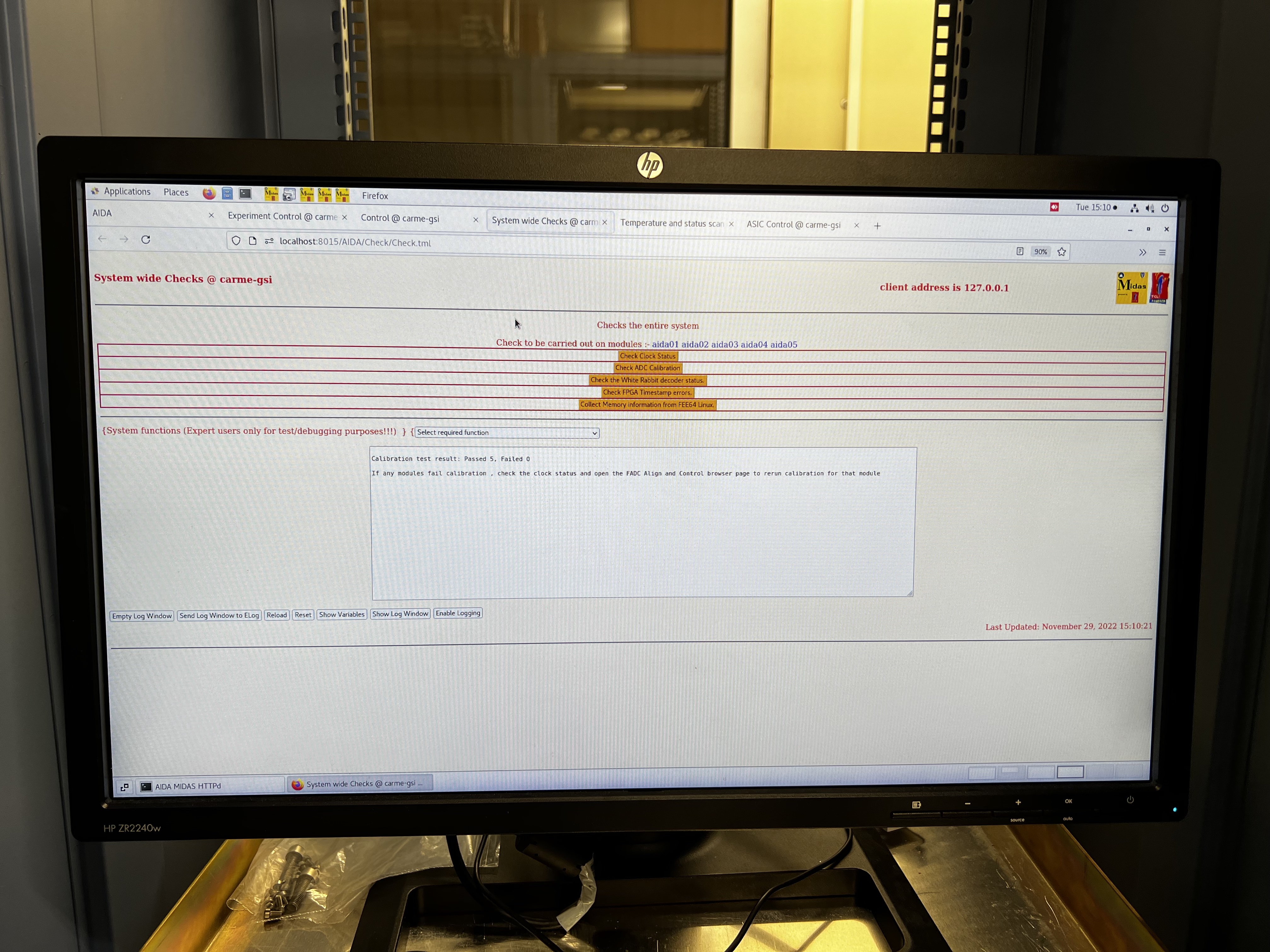
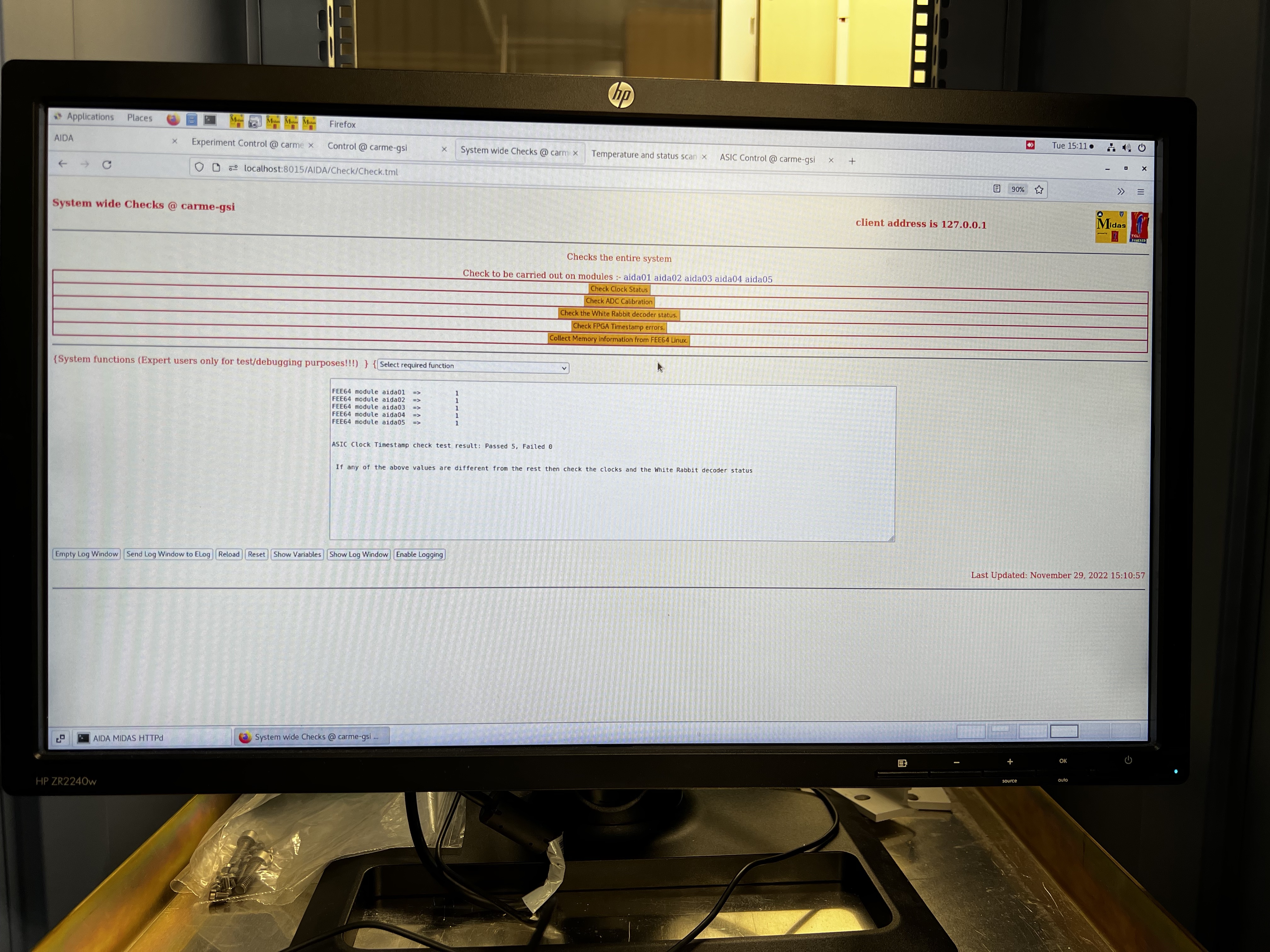
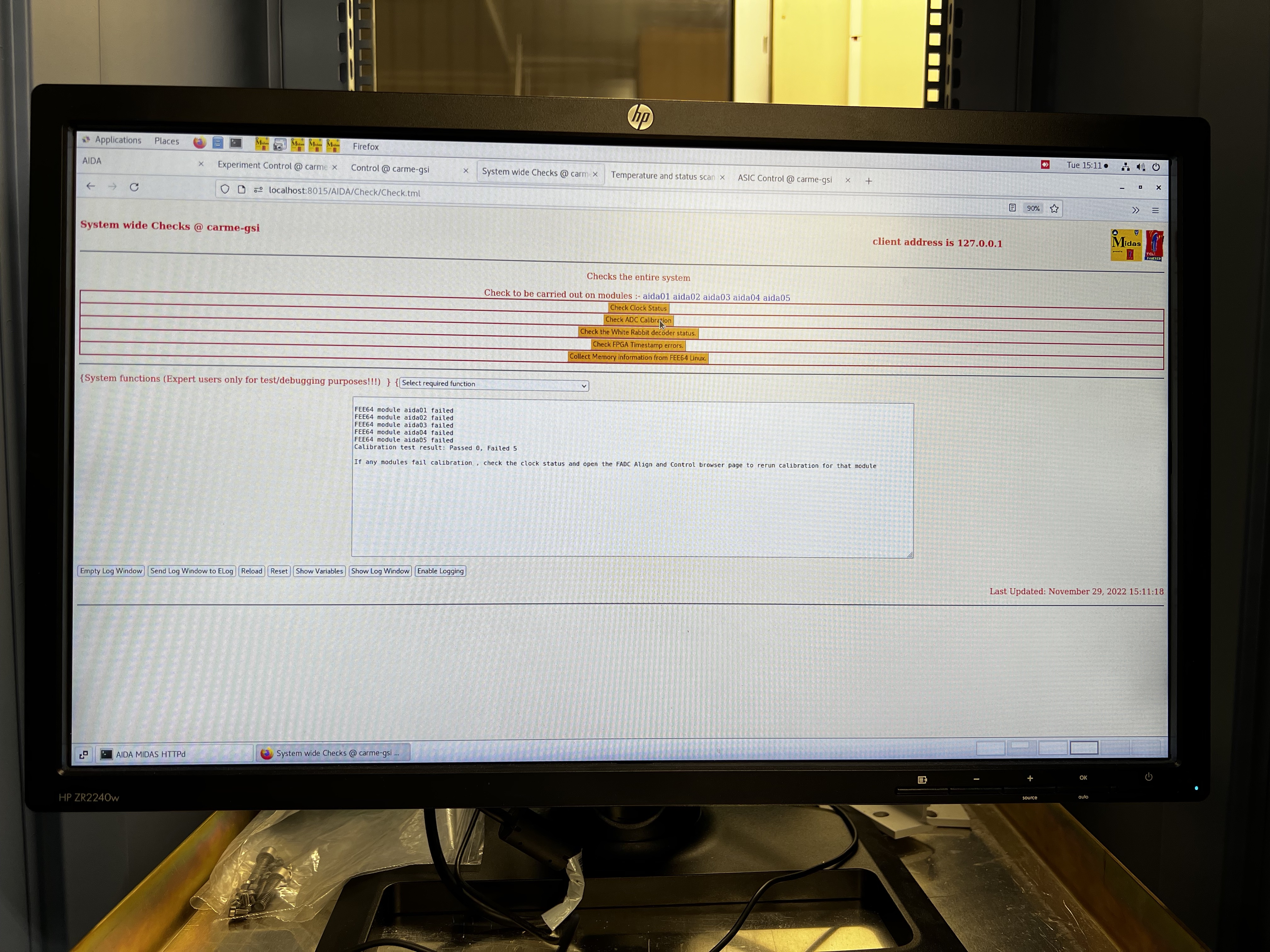
DSSD bias and leakage current values:
-99.99 V
-13.2535 uA
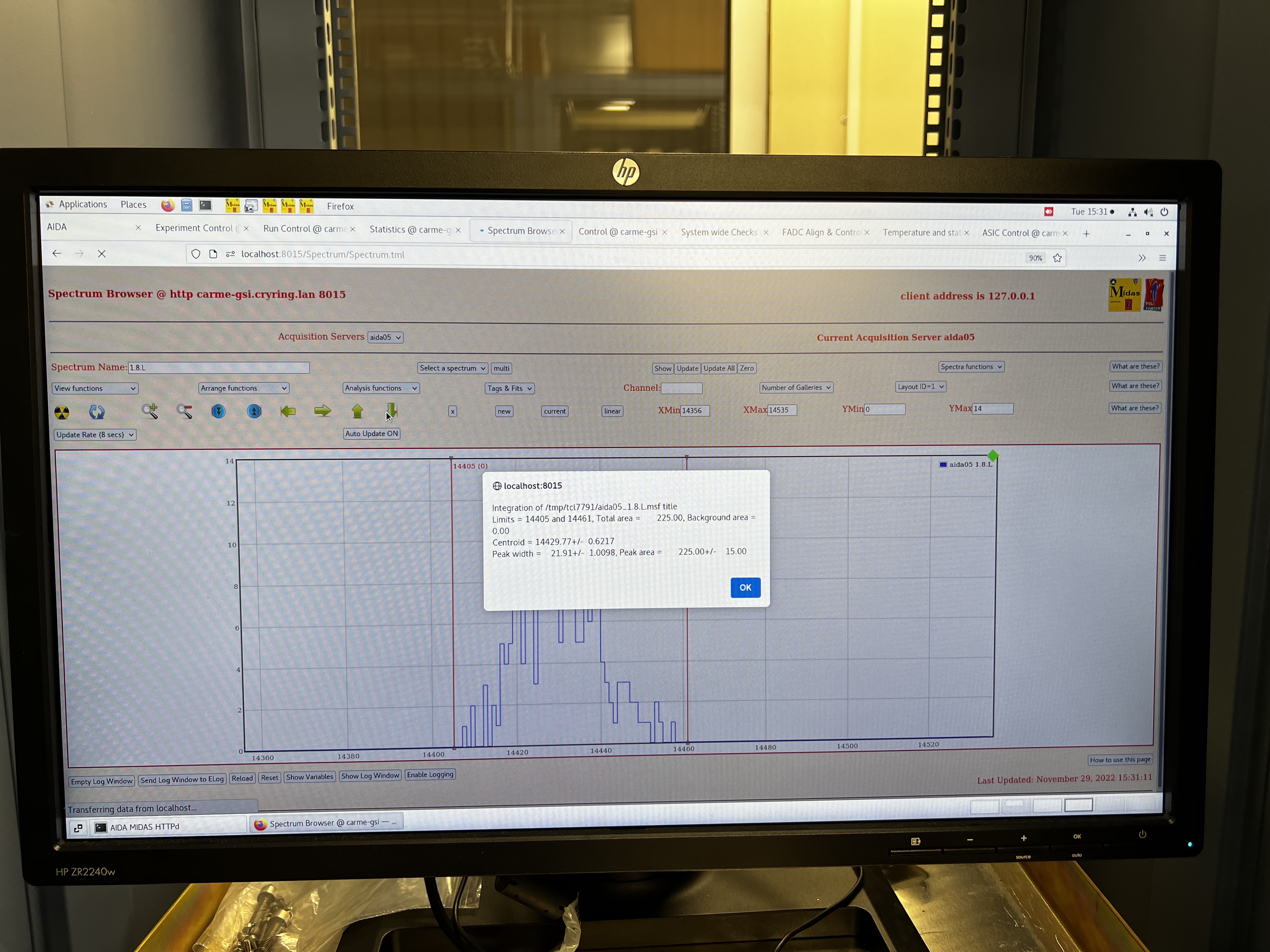
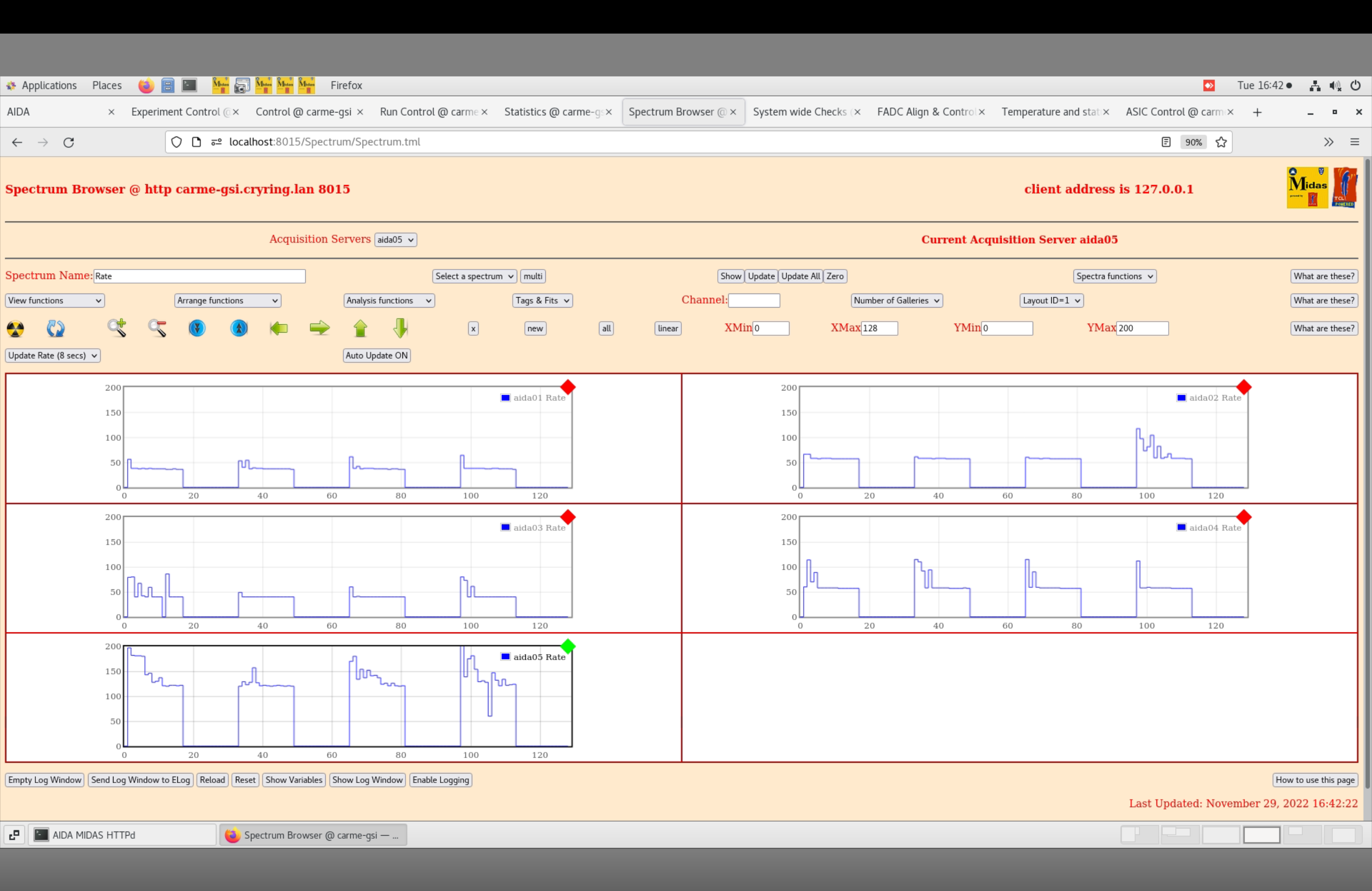
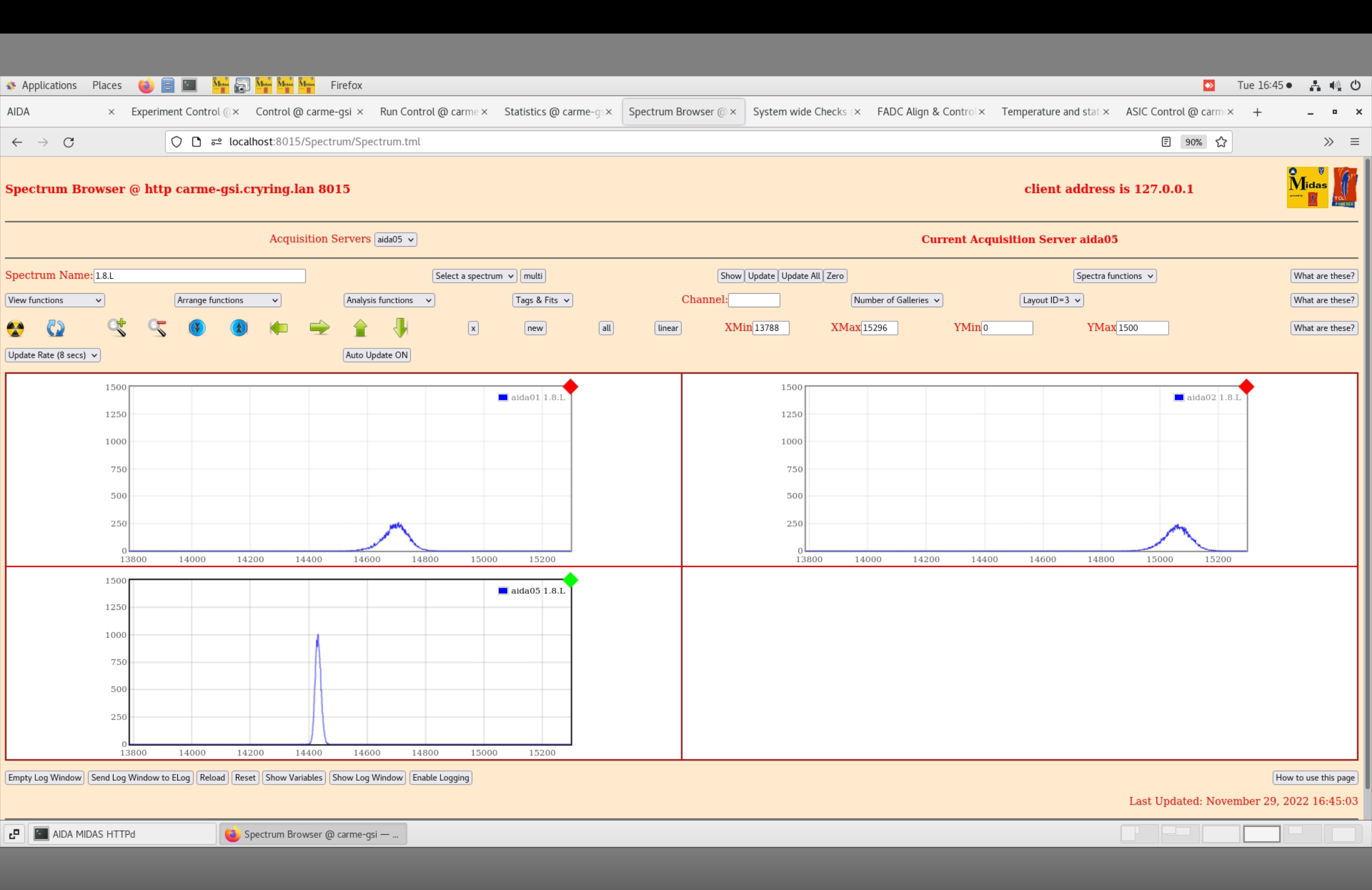
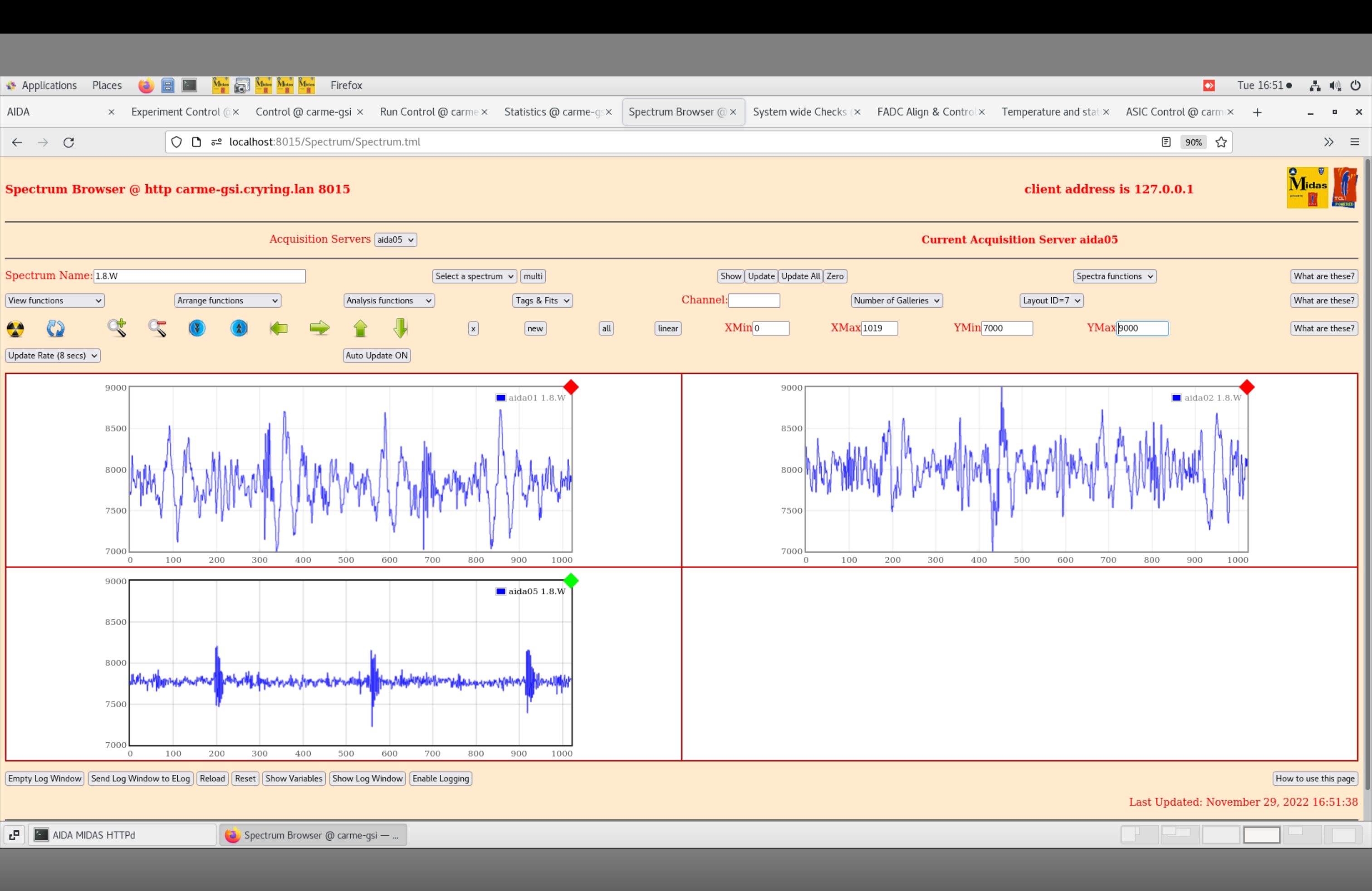
Pulsar peak widths (ch FWHM)
aida01 ~ 100
aida02 ~ 103
aida03 ~ 128
aida04 ~ 133
aida05 ~ 22
Pretty similar to what was found in august https://elog.ph.ed.ac.uk/CARME/377
|
| Attachment 1: IMG_8240_3.jpg
|
|
| Attachment 2: IMG_8241_3.jpg
|

|
| Attachment 3: IMG_8242_3.jpg
|

|
| Attachment 4: IMG_8243_3.jpg
|
|
| Attachment 5: IMG_8246_3.jpg
|
|
| Attachment 6: IMG_8247_3.jpg
|

|
| Attachment 7: IMG_8248_3.jpg
|
|
| Attachment 8: IMG_8249_3.jpg
|

|
| Attachment 9: IMG_8250_3.jpg
|
|
| Attachment 10: IMG_8252_3.jpg
|

|
| Attachment 11: IMG_8253_3.jpg
|
|
| Attachment 12: IMG_8254_3.jpg
|

|
| Attachment 13: IMG_8255_3.jpg
|

|
| Attachment 14: IMG_8257_3.jpg
|
|
| Attachment 15: IMG_8258_3.jpg
|

|
| Attachment 16: IMG_8259_3.jpg
|
|
| Attachment 17: IMG_8264_3.jpg
|
|
| Attachment 18: Screenshot_2022-11-29_at_16.40.13.png
|
|
| Attachment 19: Screenshot_2022-11-29_at_16.42.37.png
|
|
| Attachment 20: Screenshot_2022-11-29_at_16.47.03.png
|

|
| Attachment 21: Screenshot_2022-11-29_at_16.49.07.png
|
|
| Attachment 22: Screenshot_2022-11-29_at_16.49.44.png
|

|