| ID |
Date |
Author |
Subject |
|
444
|
Tue Sep 26 08:08:42 2023 |
TD | Tuesday 26 September |
09.07 IE514 pressure 6.4e-11 mbar, ambient temperature +20.3 deg C

      Using appc218 ( account carme ) workstation by the CARME 19" rack

      ssh pi@carmebakingpi

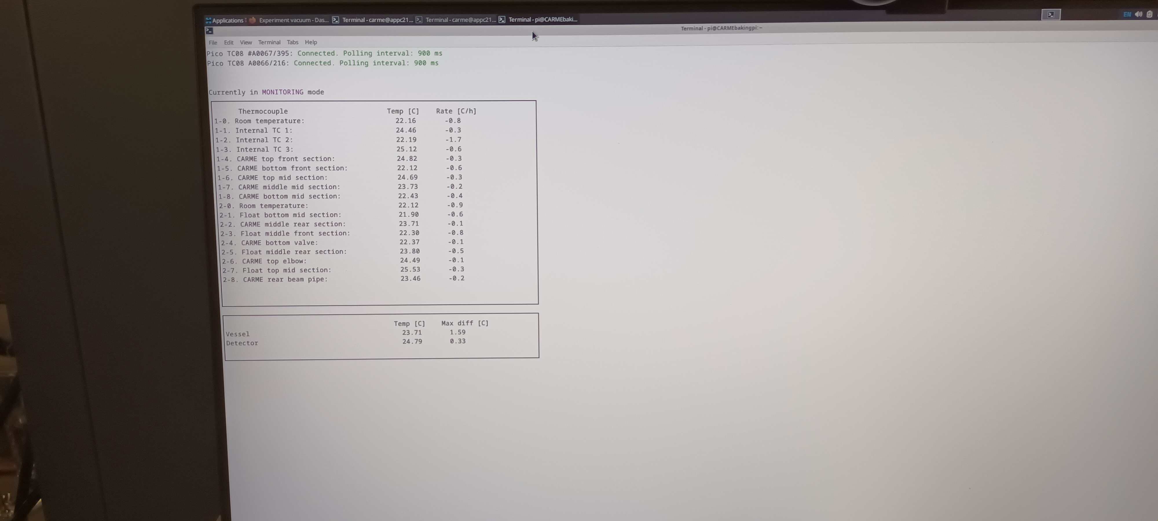
      Re-connect to bakeout monitor app

      screen -dR

      See attcahment 1


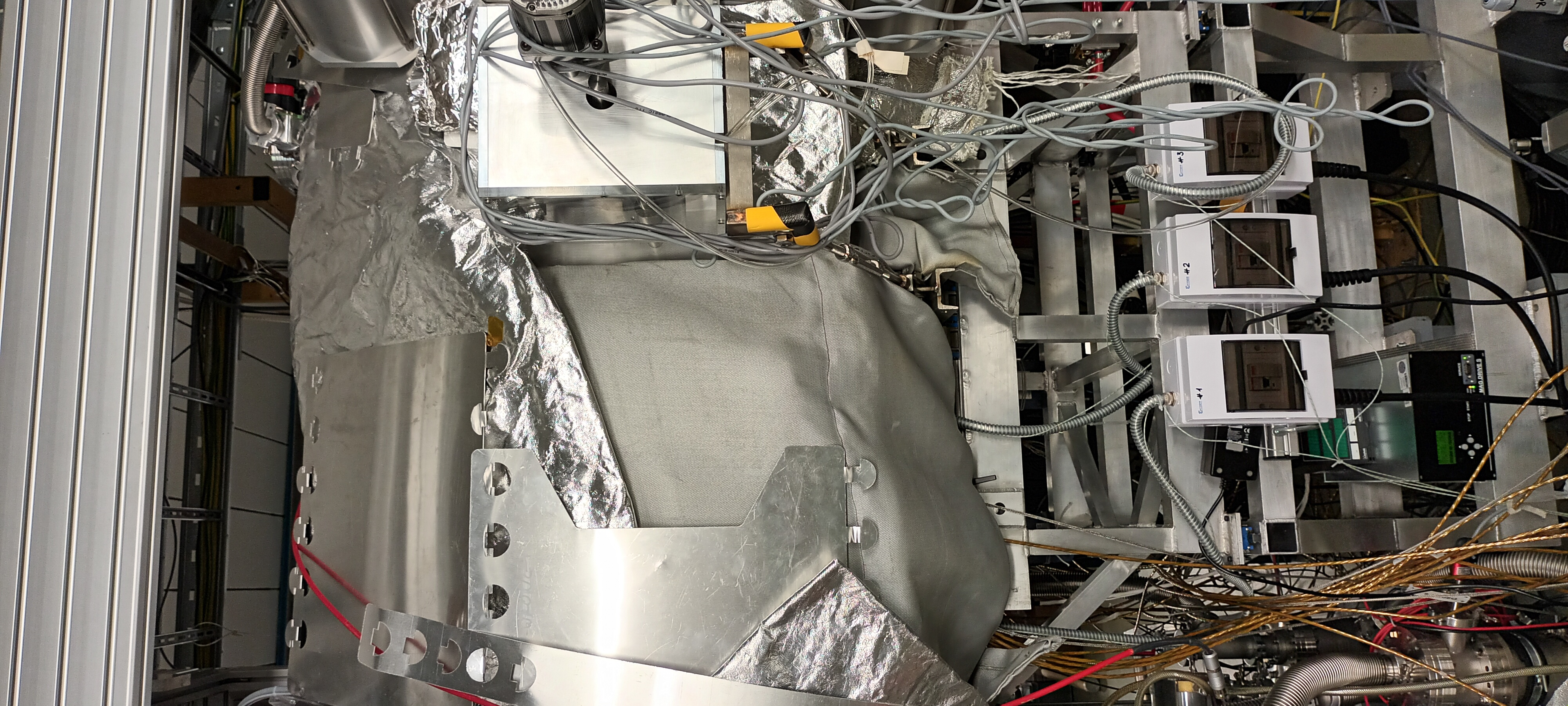
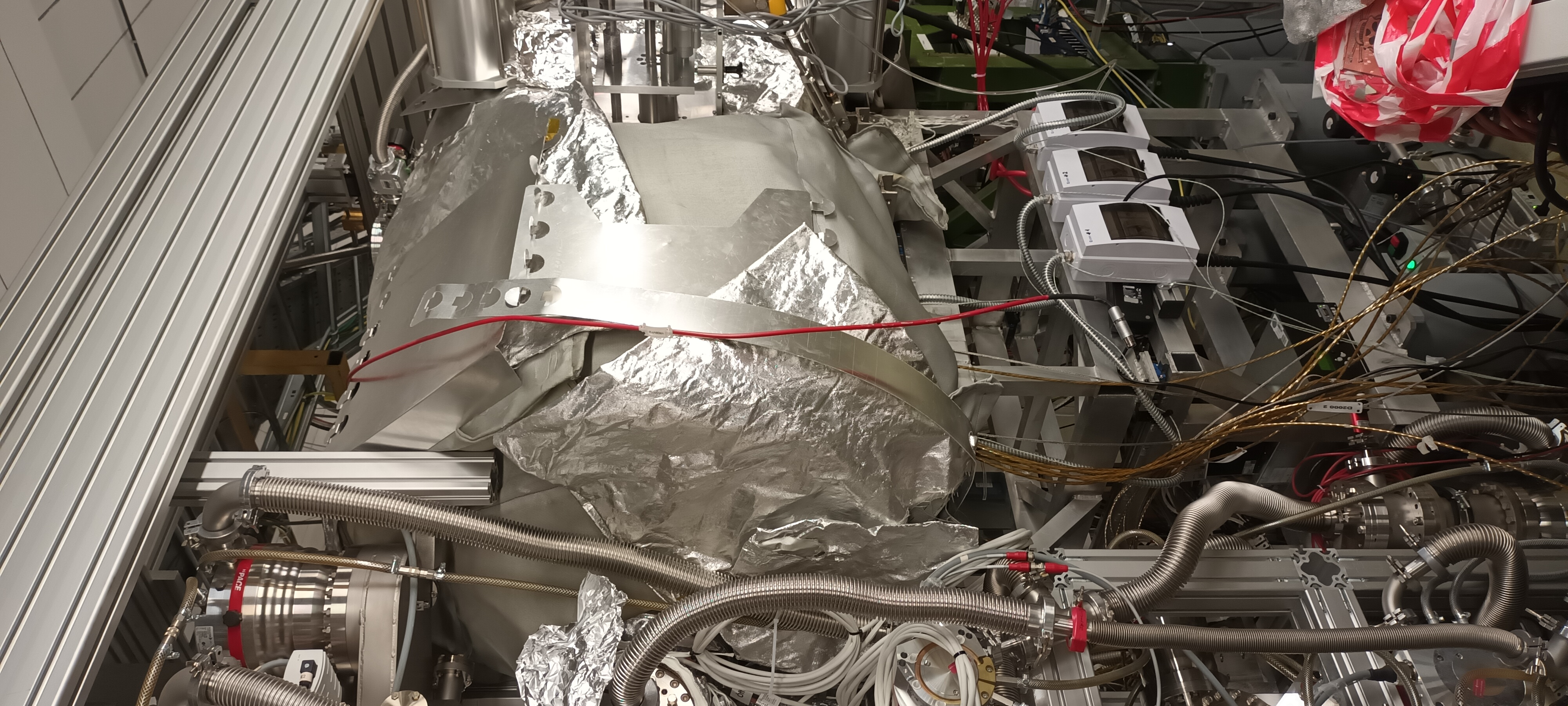
12.02 Vacuum group ion pump disconnected and RGA removed from CARME chamber -  outside of CARME bakeout tent 'closed' - see attachments 2-4

      Vacuum group IE514 to be disconnected


14.45 Vacuum group disconnect their IE514

      Inside of CARME bakeout tent closed

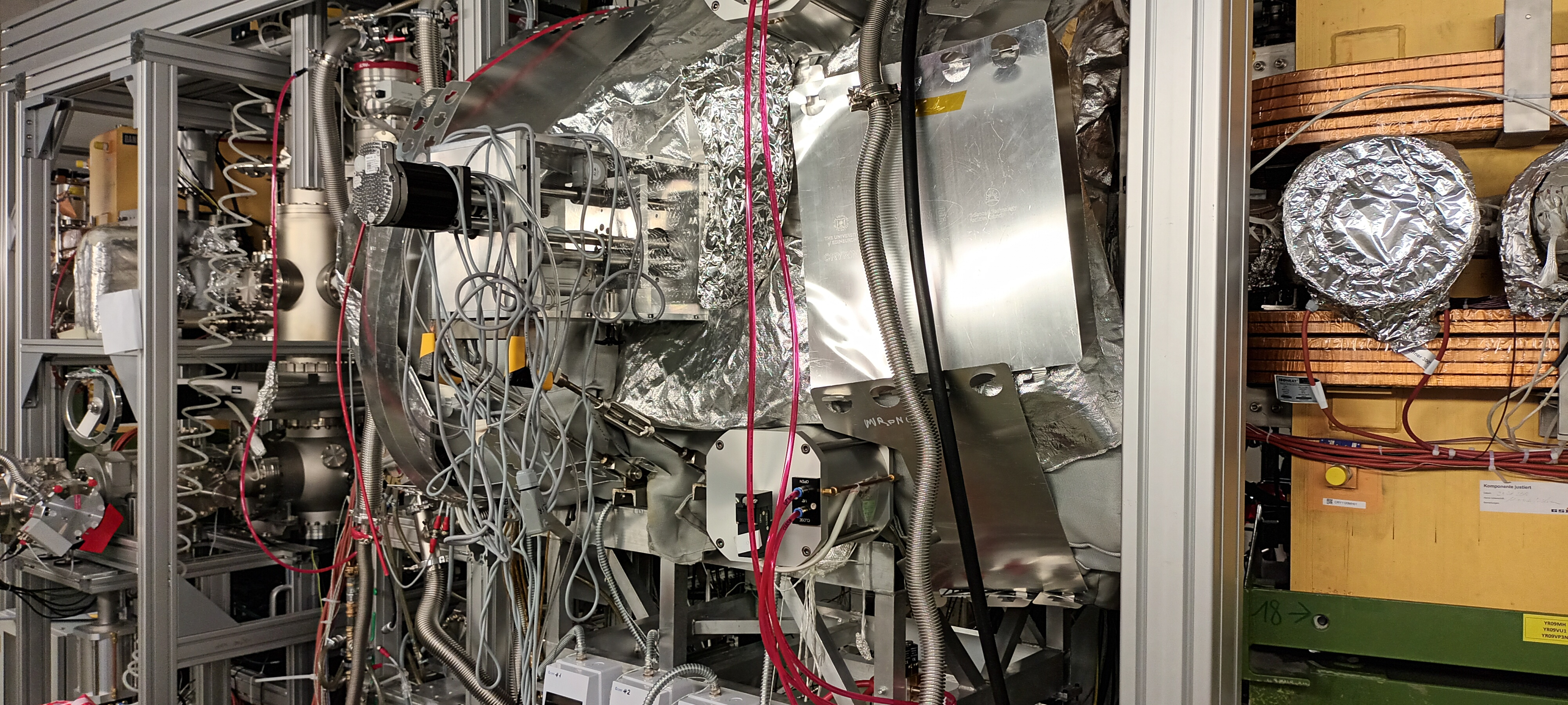
Photos of the CARME bakeout tent inside and outside CRYRING - see attachments 5-7 |
| Attachment 1: 1000007087.jpg
|
|
| Attachment 2: 1000007090.jpg
|
|
| Attachment 3: 1000007091.jpg
|

|
| Attachment 4: 1000007089.jpg
|
|
| Attachment 5: 1000007096.jpg
|
|
| Attachment 6: 1000007095.jpg
|

|
| Attachment 7: 1000007094.jpg
|

|
|
543
|
Tue Apr 23 17:44:41 2024 |
TD | Tuesday 23 April |
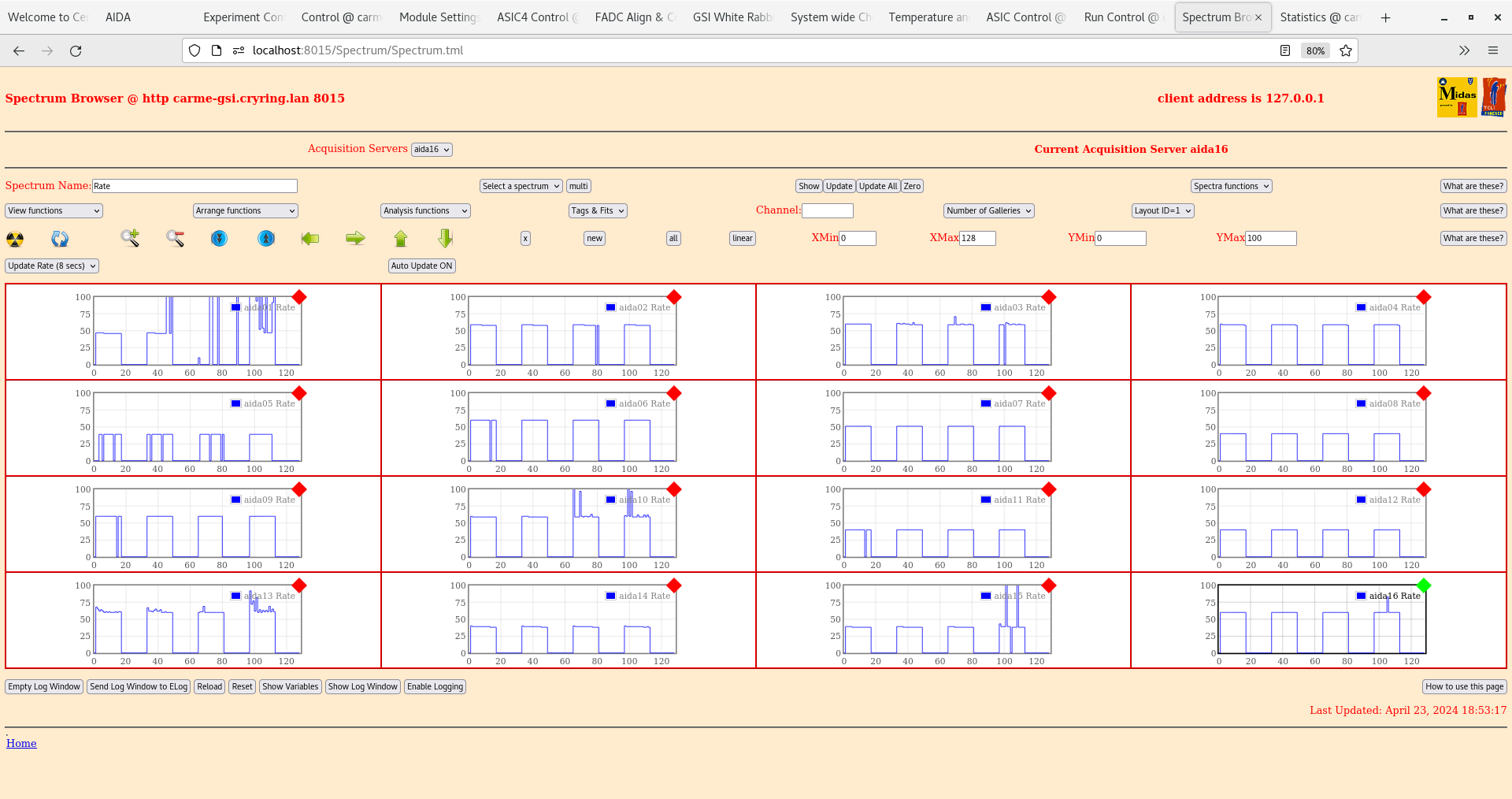
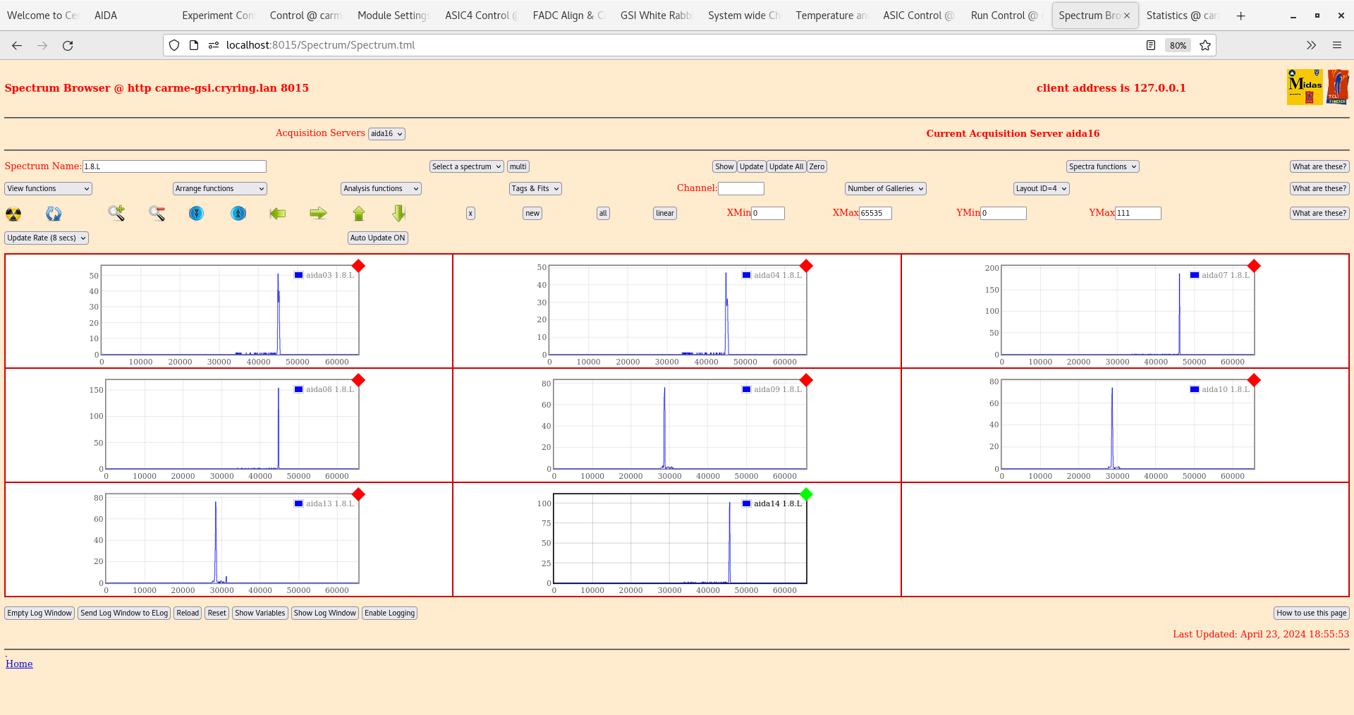
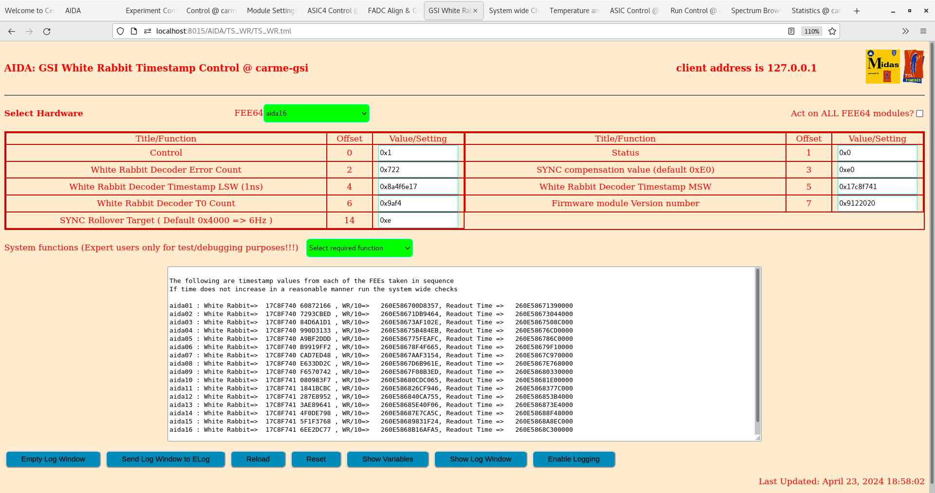
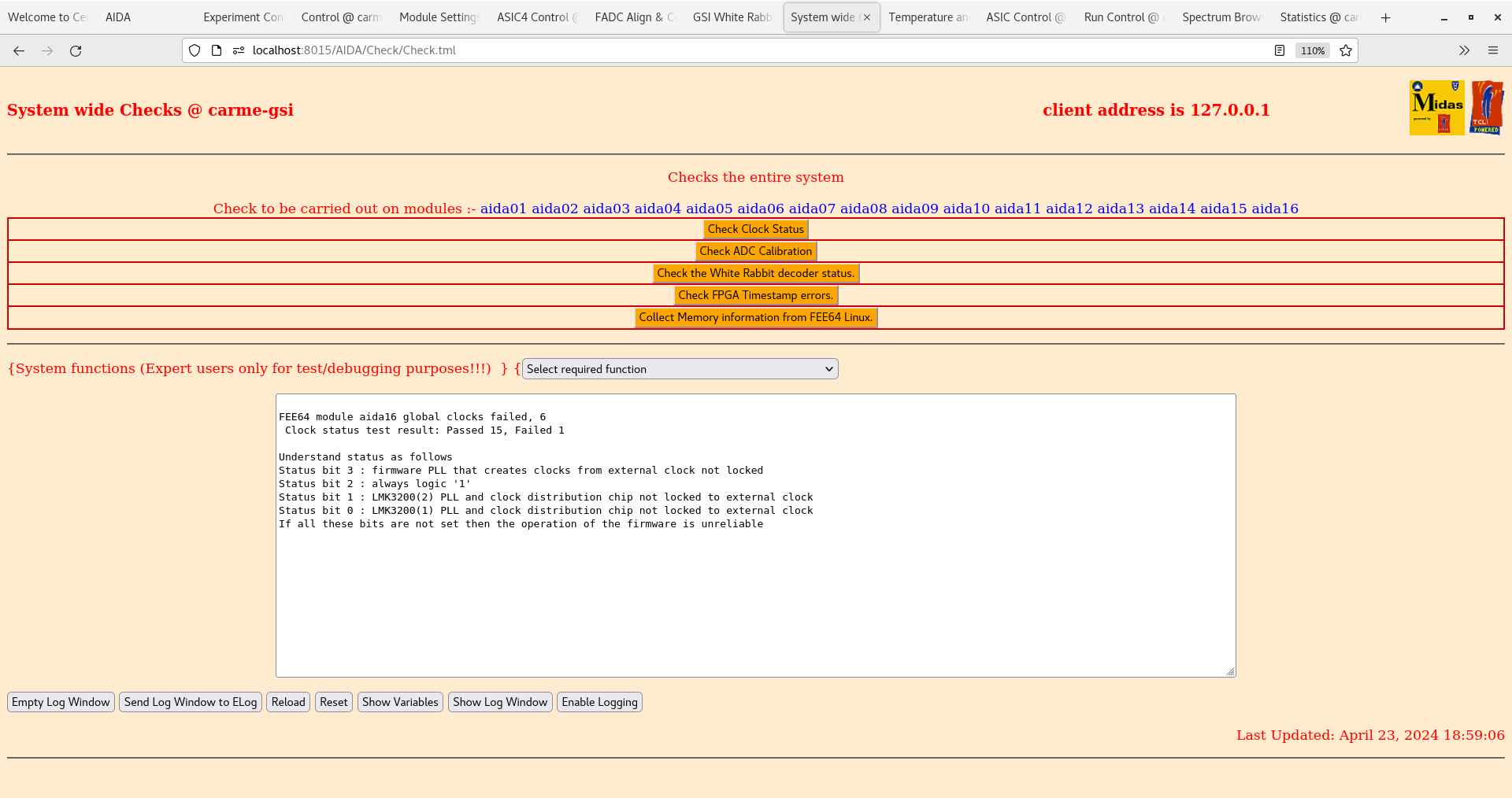
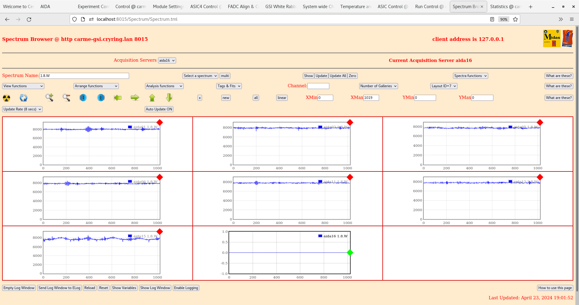
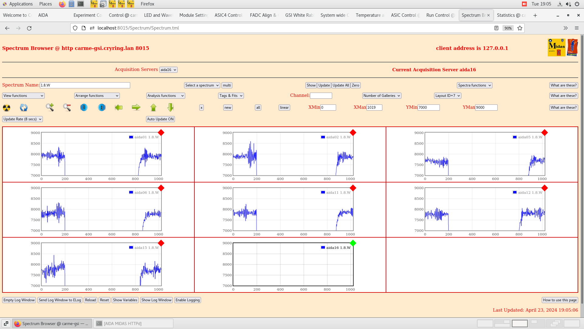
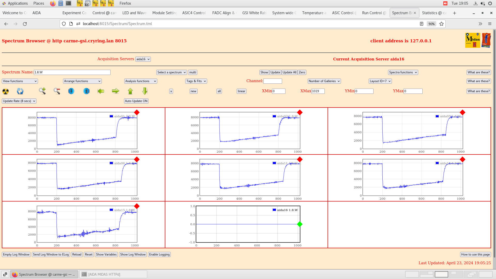
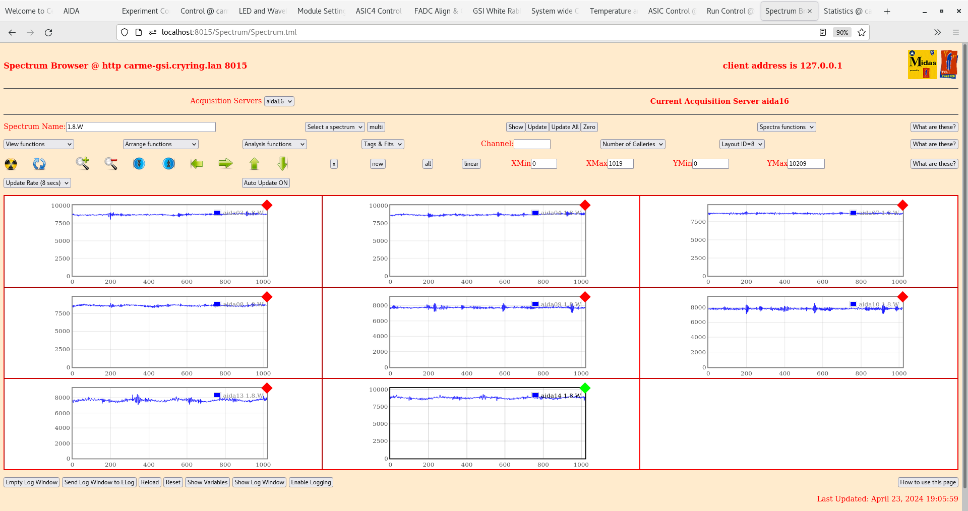
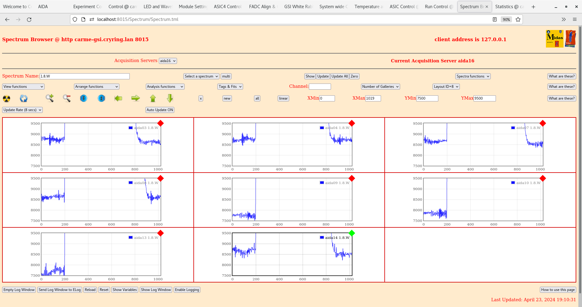
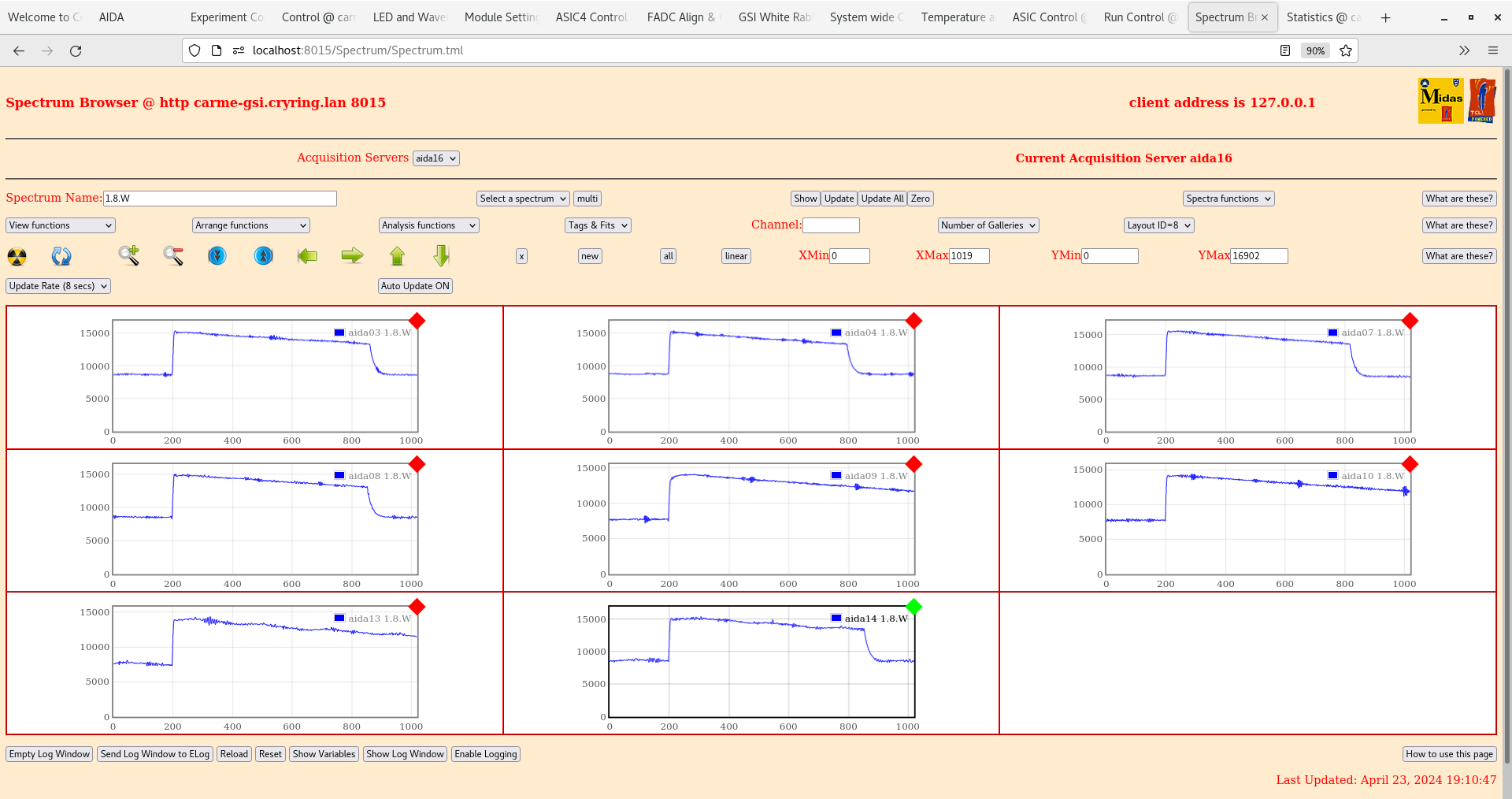
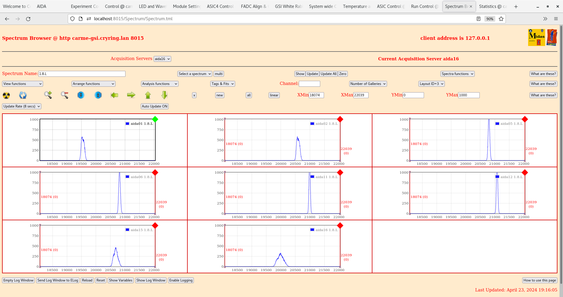
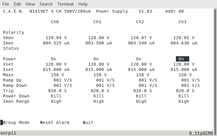
18.43 ASIC settings 2024Feb08-15.59.09

aida06 pulser peak width 66 ch FWHM |
| Attachment 1: Screenshot_from_2024-04-23_18-53-39.png
|
|
| Attachment 2: Screenshot_from_2024-04-23_18-56-31.png
|
|
| Attachment 3: Screenshot_from_2024-04-23_18-58-49.png
|
|
| Attachment 4: Screenshot_from_2024-04-23_18-59-18.png
|
|
| Attachment 5: Screenshot_from_2024-04-23_19-02-02.png
|
|
| Attachment 6: Screenshot_from_2024-04-23_19-05-12.png
|
|
| Attachment 7: Screenshot_from_2024-04-23_19-05-42.png
|
|
| Attachment 8: Screenshot_from_2024-04-23_19-06-15.png
|
|
| Attachment 9: Screenshot_from_2024-04-23_19-10-40.png
|
|
| Attachment 10: Screenshot_from_2024-04-23_19-14-23.png
|
|
| Attachment 11: Screenshot_from_2024-04-23_19-16-12.png
|
|
| Attachment 12: Screenshot_from_2024-04-23_19-16-46.png
|
|
|
18
|
Wed Sep 23 13:34:04 2020 |
JM | Tuesday 22 September |
Turbo-pump Issue approximately 13:00 22/9/20.
While moving the baking octagon into position, the power connector became disconnected from the turbo pump. The pump controller provided the warnings of connector failure and high pump load (probably due to it reading the frequency of the pump as 0 Hz when disconnected and thinking this was due to a high pump load). I believe the valve then was slightly knocked causing a vibration in the turbo, which couldn't be corrected for by the controller as it had become disconnected. The result of this was the turbo noise growing louder (similar to the turbo in the edinburgh lab when venting). At the time I didn't know the connector had become disconnected, as it was still attached to the turbo, and due to the warning messages on the controller, noise of the turbo and lack of information on what had happend, I decided to close the valve connecting the chamber to the turbo and vent the backing line up to the turbo and in order to remove and replace the turbo.
The chamber was in the high -6 mbar range when the valve was closed. The turbo was replaced with the second turbo which began pumping again (with the power connector properly secured this time) on 23/9/20. The turbo doesn't show any obvious sign of damage, the blades in it are free to spin with no hindrance, but we will have to get it tested by the vac lab to be sure. |
|
679
|
Tue Apr 22 06:44:02 2025 |
TD | Tuesday 22 April |
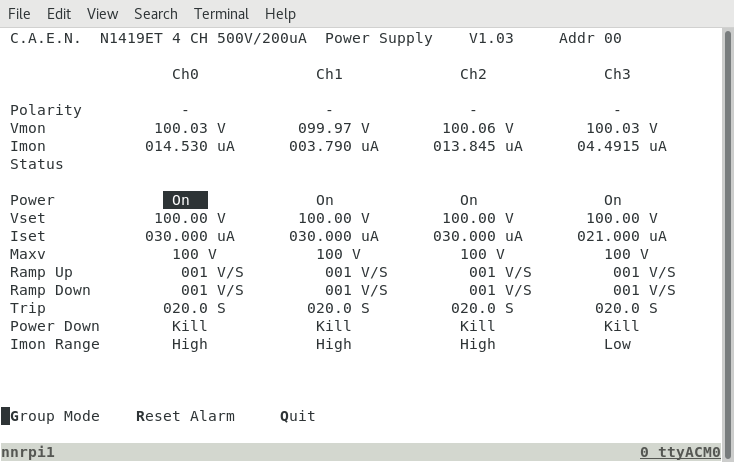
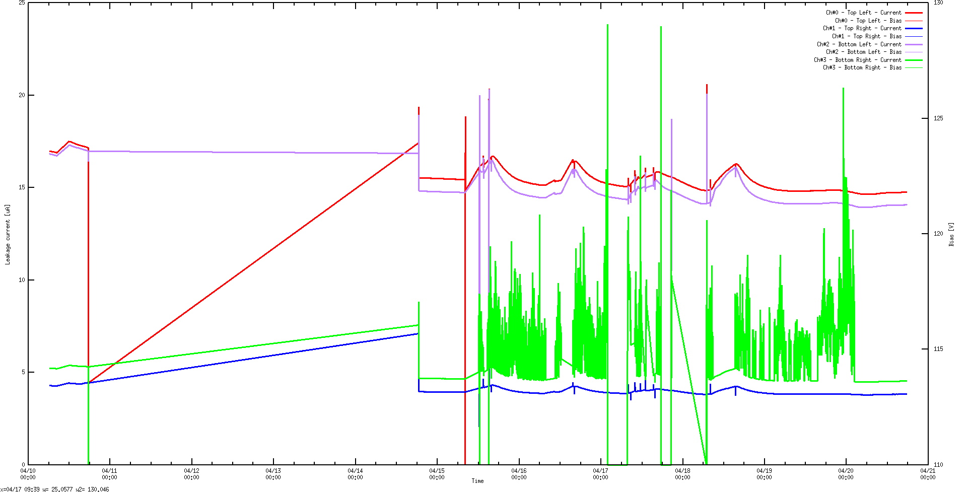
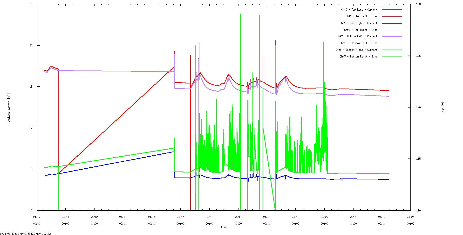
07.40 DSSSD bias & leakage current - attachments 1-3
       CAEN logger program crashed c. 18.00 April 20 - now restarted
       DSSSD #2 and DSSSD #4 OK - DSSSD #4 stable since c. 03:00 20.4.25
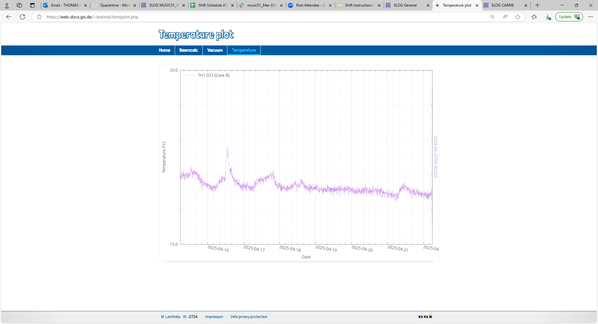
       DSSSD #1 and DSSSD #3 remain high with slow decrease (ambient temperature approx stable c. 16.5 deg C)

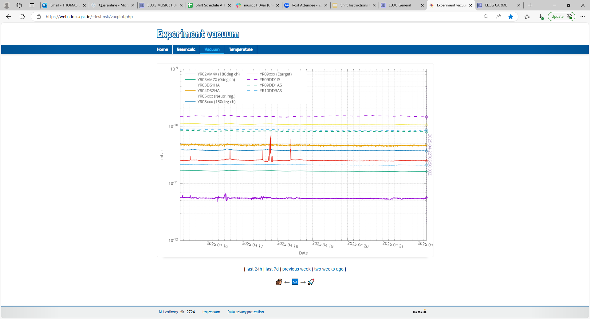
CRYRING vacuum and temperature - attachments 4-5 |
| Attachment 1: Screenshot_from_2025-04-22_07-40-45.png
|
|
| Attachment 2: Screenshot_from_2025-04-22_07-41-10.png
|
|
| Attachment 3: Screenshot_from_2025-04-22_07-47-25.png
|
|
| Attachment 4: 1.png
|
|
| Attachment 5: 2.png
|
|
|
469
|
Tue Jan 16 08:57:44 2024 |
JG, DR, TD | Tuesday 16 January |
10.00 Outflow manifold returned from workshop with leaking attachment point welding re-worked.

11.30 Outflow hoses re-attached to outflow manifold. Faulty male Swagelok replaced.
      Outflow manifold tested on floor - no leaks observed.

      Mounted outflow manifold. All inflow/outflow hoses attached to FEE64s - see attachments 1-4.
      FEE64 #11 detached adaptor PCB - temporarily secured by cable tie.

      Inflow/outflow valves opened. Pin hole leak observed at 3/8" connector gasket - indicated by arrow attachment
3.
      Leak fixed by tightening fitting.

      1x spare inflow/outflow connected together - attachment 4.

11.40 CARME IE514 3.8e-11mbar, ambient temperature 16.5 deg C

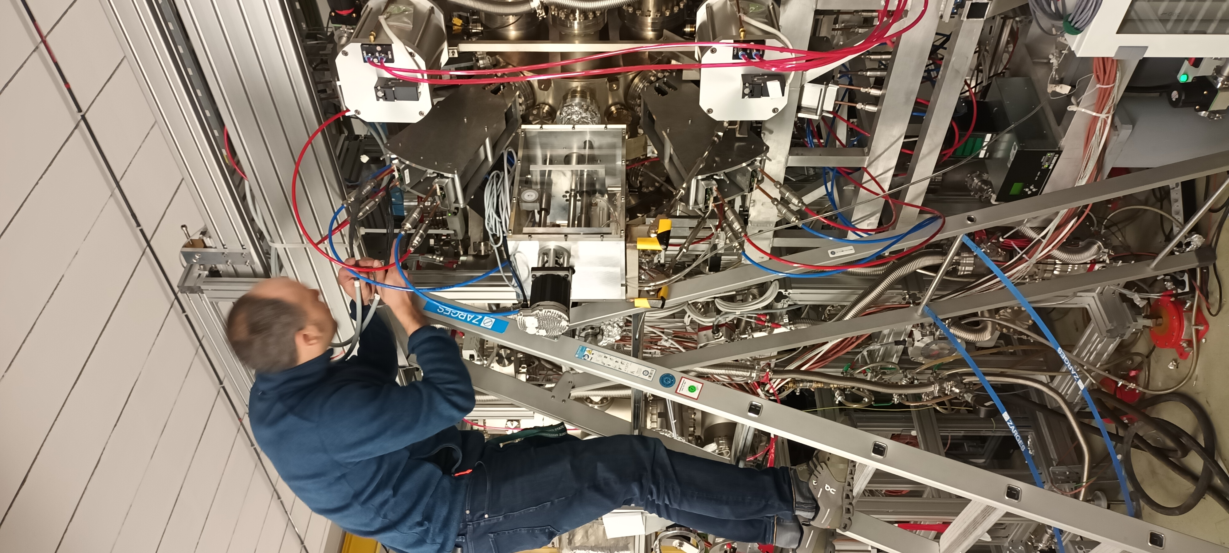
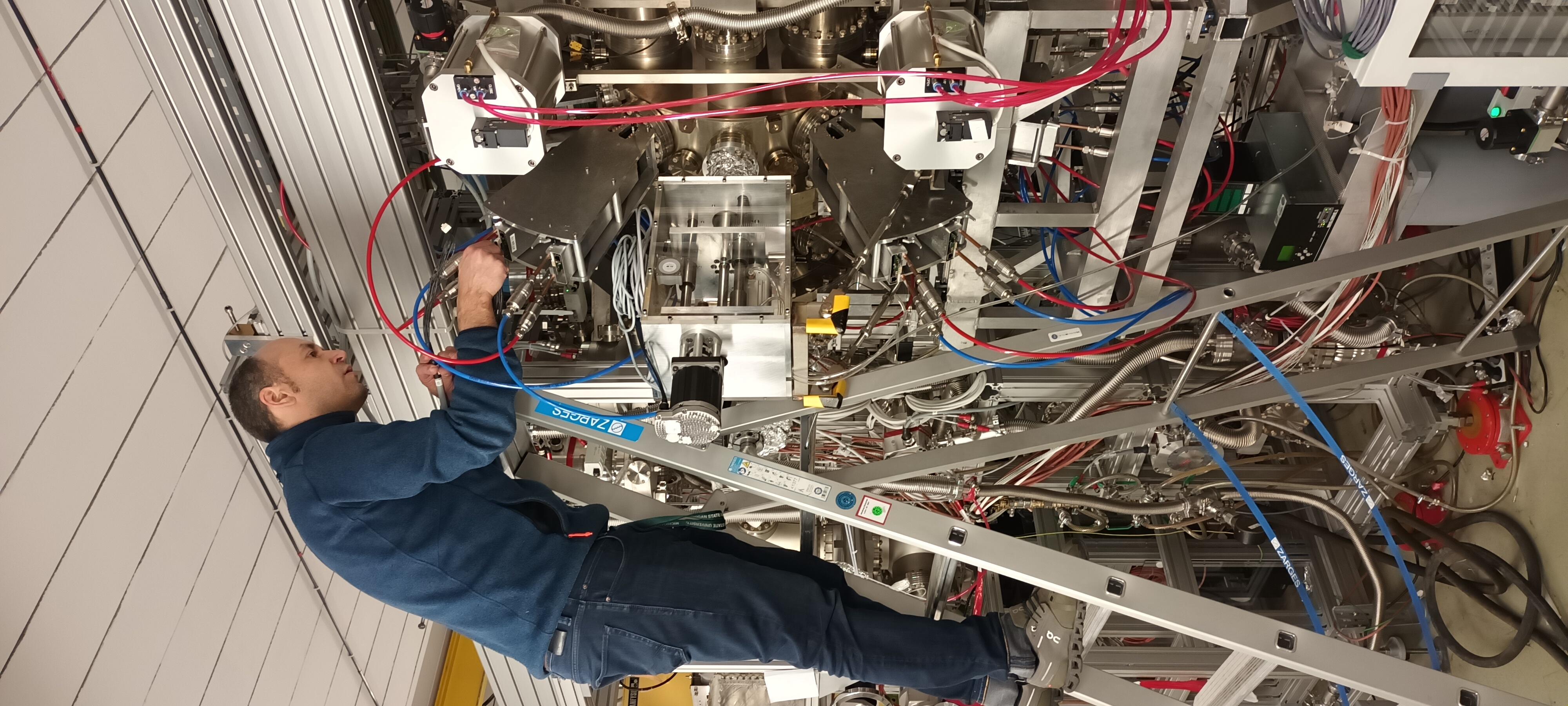
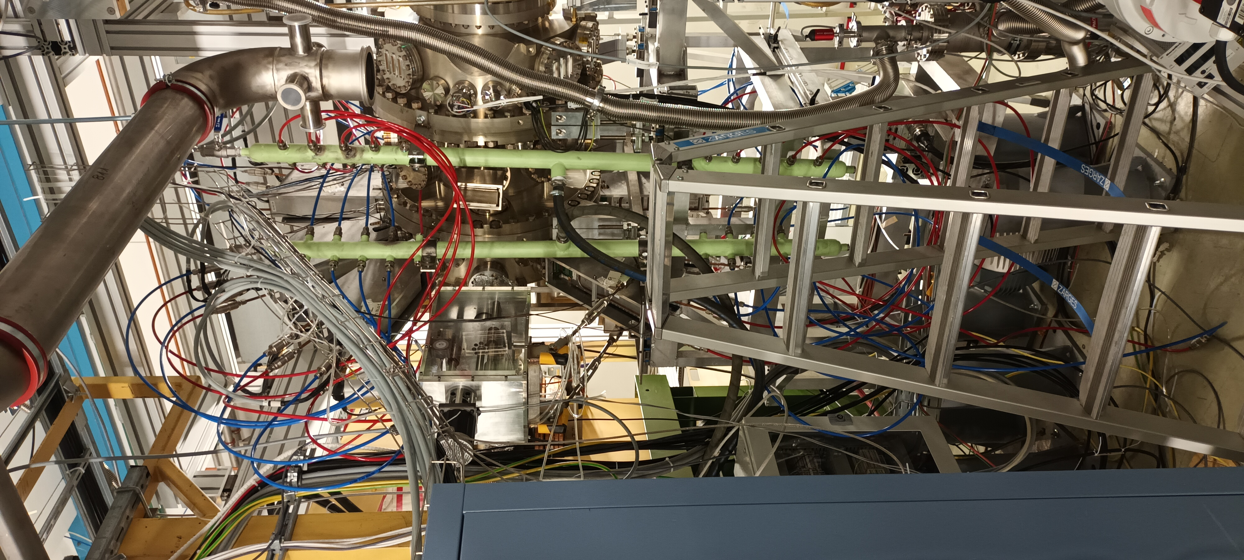
15.05 8x AIDA FEE64 power cables ( #1 - #8 ) installed FEE64s #1 - #8
      Note - Samtec lock clips broken on 3 of 8 cables due to careless handling/poor storage
      AIDA FEE64 power cables tied to one of the FEE64 copper coolant pipes.

      See attachments 5-7

15.30 USB-controlled ac mains relay - USB connected to RPi CARMEbakingpi currently used for CAEN N1419ET
      Rear panel key switched to override - no flow/d.p. sensors currently installed - front panel water ( yellow ) and override ( red ) LEDs active.

16.15 Transfer CARMEbakingpi from CRYRING network to AIDA 24-port Gbit network switch connected to carme-gsi
      CARMEbakingpi becomes nnrpi1 p- can connect OK via ssh from carme-gsi

      Start server ( port 8015 ) manually

      ssh pi@nnrpi1

      /MIDAS/Tcl/Httpd/linux-arm/Tcl-Httpd-server &

See attachment 8 |
| Attachment 1: 1000009654.jpg
|

|
| Attachment 2: 1000009651.jpg
|

|
| Attachment 3: 1000009653.jpg
|

|
| Attachment 4: 1000009652.jpg
|

|
| Attachment 5: 1000009663.jpg
|
|
| Attachment 6: 1000009662.jpg
|
|
| Attachment 7: 1000009664.jpg
|
|
| Attachment 8: Capture.PNG
|

|
|
39
|
Tue Aug 10 12:22:56 2021 |
TD RSS | Tuesday 10 August |
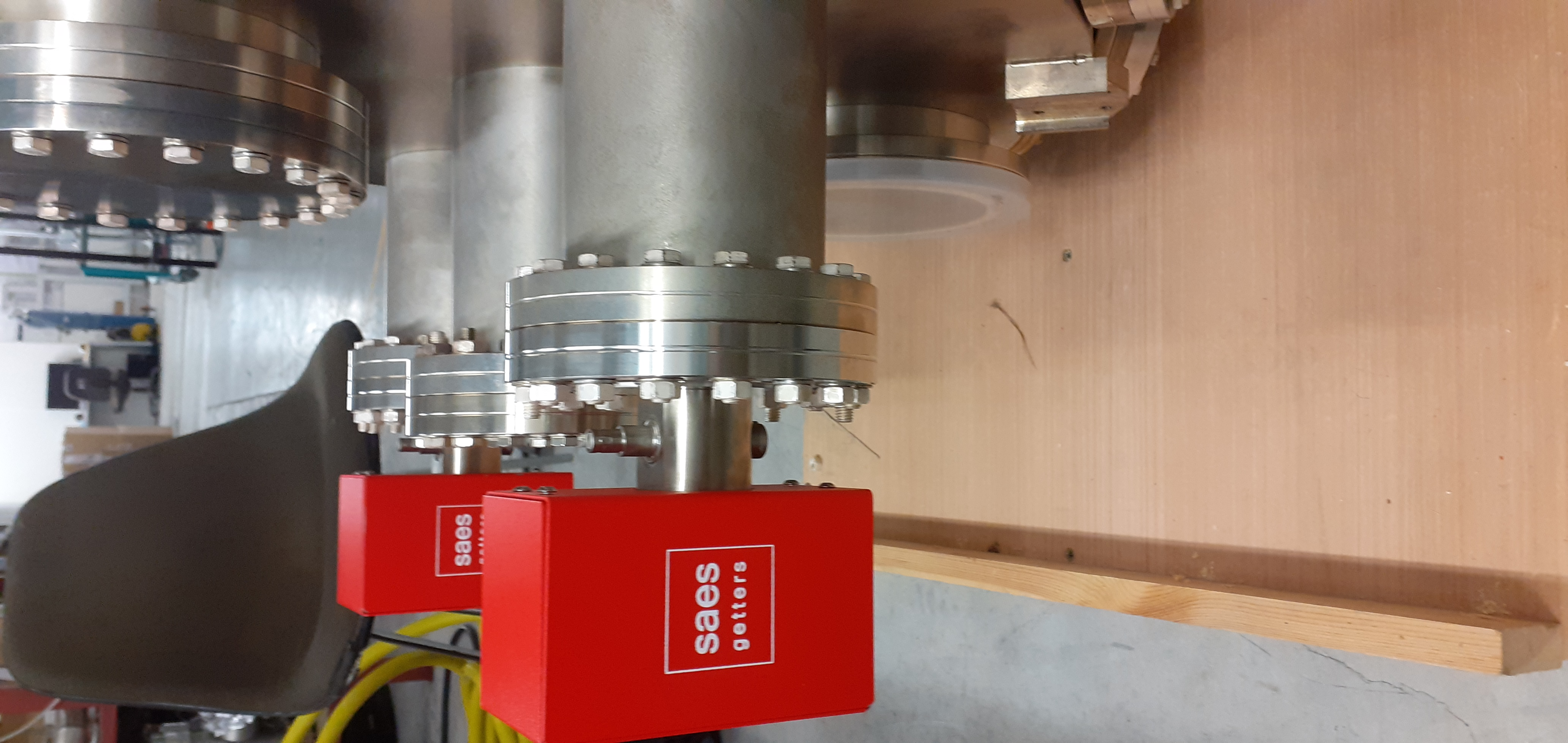
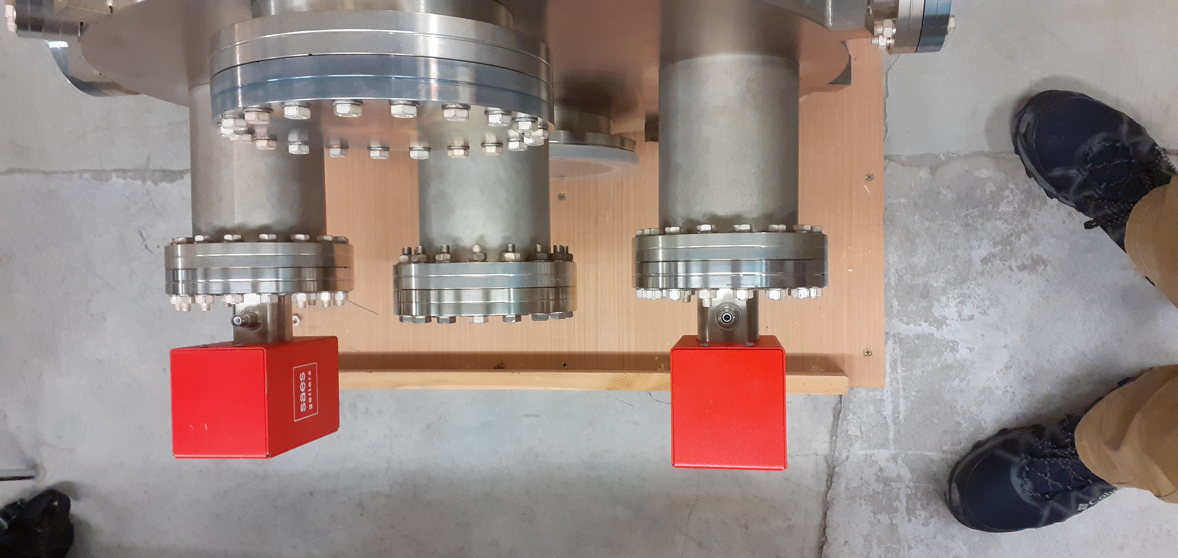
Attachments 1-3 - 2 of 4 SAES D2000 installed at same ports used for STFC DL XHV tests |
| Attachment 1: 20210810_115555.jpg
|

|
| Attachment 2: 20210810_115607.jpg
|
|
| Attachment 3: 20210810_115617.jpg
|
|
|
115
|
Sat Oct 9 09:47:33 2021 |
CB | To do list for next week |
0. Give split-funnels to OG or Grossmontage to clean. Mount back foot support for gate valves. Critical when we split.
1. Wait for vacuum division to come to install: IE514 cables to current CM52 module, ion pump cables + controls + turn on, RGA head + program + turn on
2. Vacuum division should also bring N2 gas to vent CARME. Ideally vent by Wed to avoid losing time. Remember to disable ion pumps and remove all cables when venting.
3. While waiting to vent, connect pneumatic hoses to motors box in CARME rack. There is one pneumatic in (central feedthrough) and four pneumatic out. See picture attached. Top two go to left pneumatic motor, bottom two go to right pneumatic motor. Of each set of two, one is for extending the motor and one is for retracting but unclear which is which. Try to connect and operate motor manually by pressing on buttons on top of pressure reducer to ensure everything works. Don't forget to remove the safety pin.
4. Some disassembly of the servo motors may be required to get them operational. Use the Windows ClearView program provided by Teknic to control servos and change the function of the limit switches. Download from https://teknic.com/downloads/ -> ClearPath -> Software -> ClearView Install.zip . There is a Linux version but I have never tested it. The code on the raspberry Pi cannot reproduce some of the functions in the official program due to library limitations (but can do other things the official program cannot do).
5. After venting CARME, split open at the COF600 flange close to the magnet. Open CARME by 1-2 cm, remove spherical washers from top of rail studs, and lift with crane. Make sure knife edges of the two halves do not touch. CARME currently has feet mounted and cannot easily be placed on a standard pallet. Either dismount the feet (not easy to remount), or find a pallet on which CARME can land on its belly only, or place CARME on pallet with feet and screw feet down? Discuss strategy with DR asap.
6. Install split-funnels on flanges/wire harnesses in use (no point installing on other flanges). This may require dismounting top flanges. Probably switch from 3 hole to 4 hole configuration with funnels.
7. Test detector support going to actuator rod without detector. Make sure you have all the parts, including bolt to secure support to rod. You may want to push the rod in via pneumatic motor (or by hand pushing the plate outside) to gain better access.
8. Take detector support on table, install *two* detectors on same support, and mount on actuator rod in XHV. Connect wires and close via jacking plates. Optionally, consider mouting empty support on other rod? May be useful for diagnostic/scraping?
9. Move XHV thermocouple feedthrough to top flange and connect one thermocouple per detector, one to the support, and leave one floating inside
10. If the motors are fully operational, check how far/close they can be actuated from chamber wall. If not, take some dimensions for future reference.
11. Lift CARME back in place. Close using Pfeiffer COF600 seal and ~72 Nm force per bolt. 80 Nm were required in DL. Probably get Grossmontage to do this. Use our long torque-wrench.
12. Connect to interaction chamber via bellows. Beware gaskets on one side are non standard. One appropriate gasket should be on top of bellows box.
13. Reconnect pumps, rebuild octagon, reconnect thermocouples, rebuild baking tent, bake. Make sure to label the NEG cables this time!
14. Activate NEG pumps following this recipe. ALWAYS monitor temperature and be ready to stop if detector temperature reaches 120 C. NEG temperature does not drop immediately, don't wait until it is too late.
If temperature is increasing too quickly (check rates/h), decrease activation power in increments of 25 W. Remember to flash ion pumps.
A. Start from D2000. Activate one at a time with T 400 C, t rise 30 min, t hold 90 min. Activating a second D2000 while the first has reached its hold state seems safe. Leave at 250 C to keep clean.
B. Continue with UVH1400 furthest from the detector (DSSD wall chamber). Activate at P 200 W, t rise 30 min, to hold 90 min. Finish one set of two before moving to the second. Leave at 50 W to keep clean.
C. Continue with UHV1400 in intermediate chamber. Activate at P 150 W, rest as above. Leave at 50 W to keep clean.
D. Continue with 2xUHV1400 closest to detectors. Activate at P 70 W, rest as above. Leave at 50 W to keep clean.
E. Finish with 3xUHV1400 closest to detectors. Activate at P 90 W, rest as above. Turn all NEGs off when activation of 3x is complete.
F. Let chamber cool. Activate ion pumps at room temperature. Section off turbo pump. |
| Attachment 1: Capture.PNG
|

|
|
447
|
Thu Sep 28 09:19:50 2023 |
TD | Thursday 28 September |
10.20 CARME IE514 8.6e-11 mbar

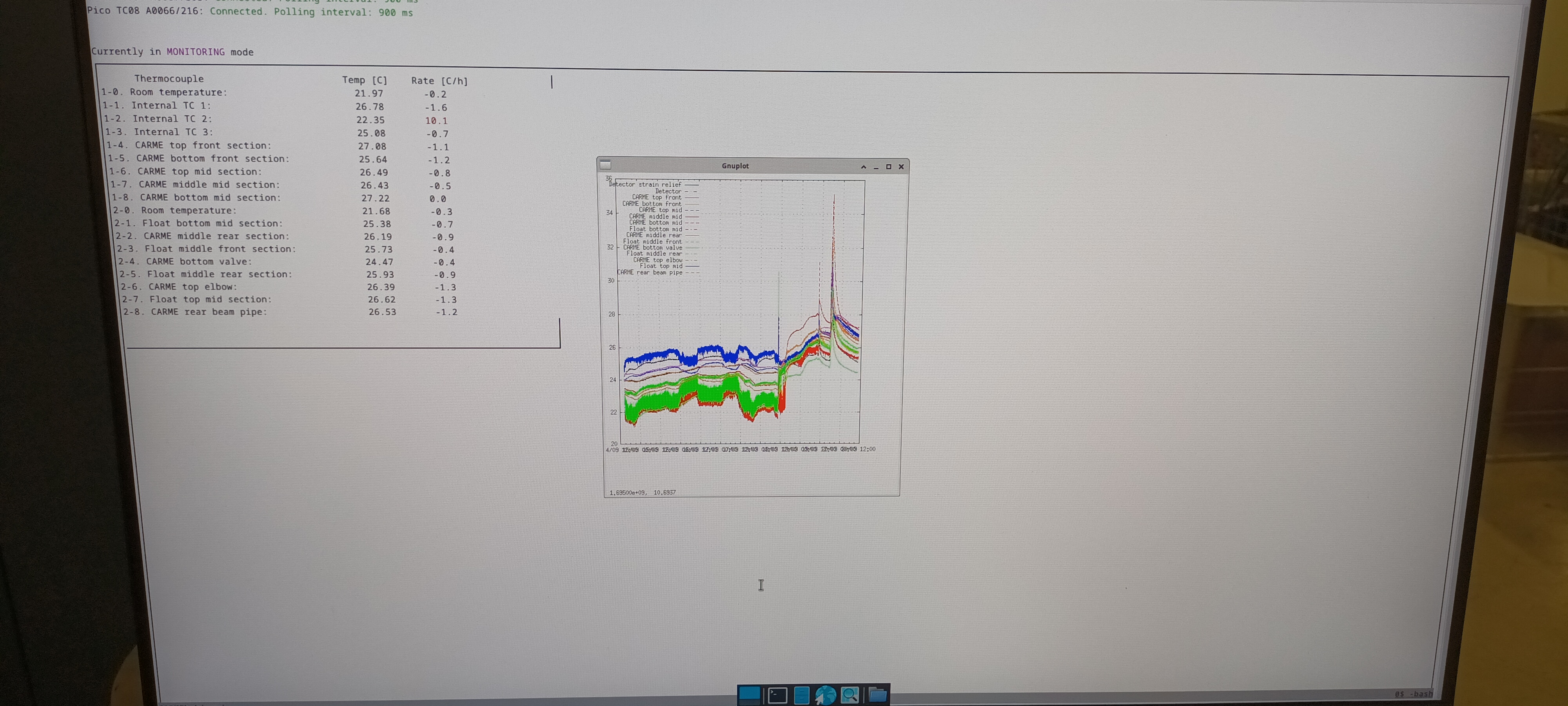
      CARME bakeout monitor and ELOTECH bakeout controller status - see attachments 1 & 2

      The CARME bakeout monitor shows recovery from test yesterday evening. The ELOTECH controller was switched to manual mode for the 3x CARME zones and 5% power selected
for 45 minutes. CARME TCs increased from mid-20s to high 20s/low 30s over a period of 45 minutes. At the conclusion of the test power was set to 0% for all 3x CARME zones
and the mode changed from manual to controlled. |
| Attachment 1: 1000007142.jpg
|
|
| Attachment 2: 1000007143.jpg
|

|
|
546
|
Thu Apr 25 02:31:25 2024 |
TD | Thursday 25 April |
03.27 DAQ continues - file APR24/R1_7

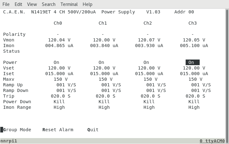
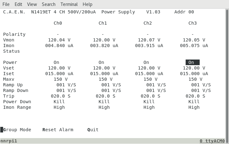
      DSSSD bias & leakage current OK - attachment 1
      ambient temperature 16.1 deg C

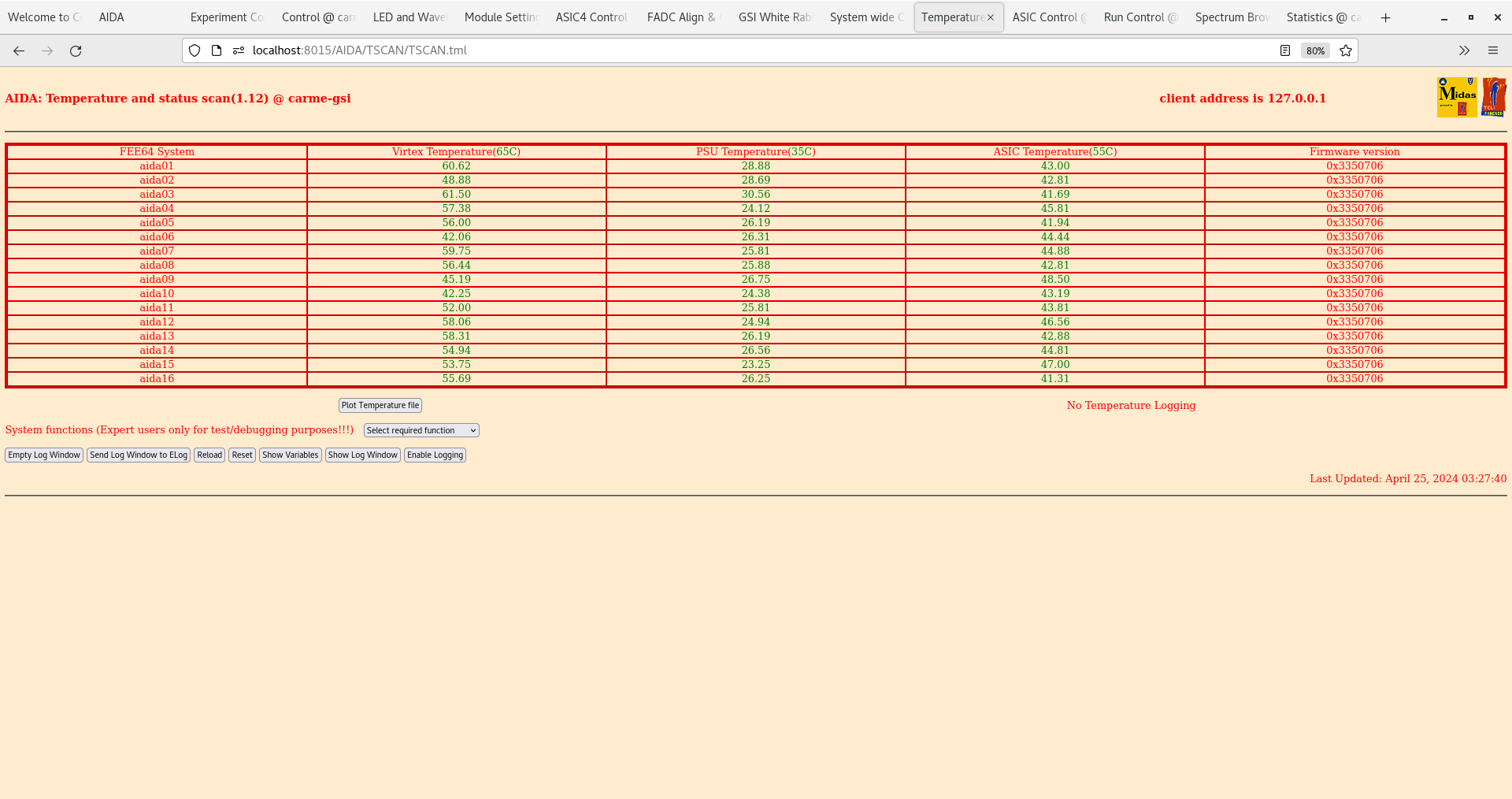
      FEE64 temperatures OK - attachment 2

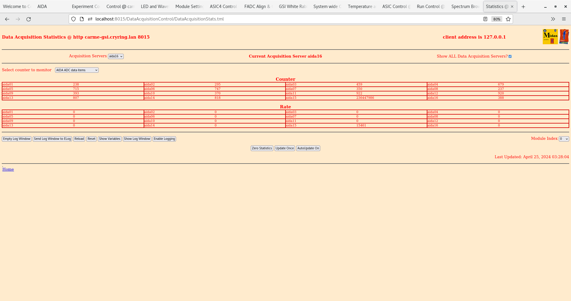
      ADC data item stats OK - attachment 3

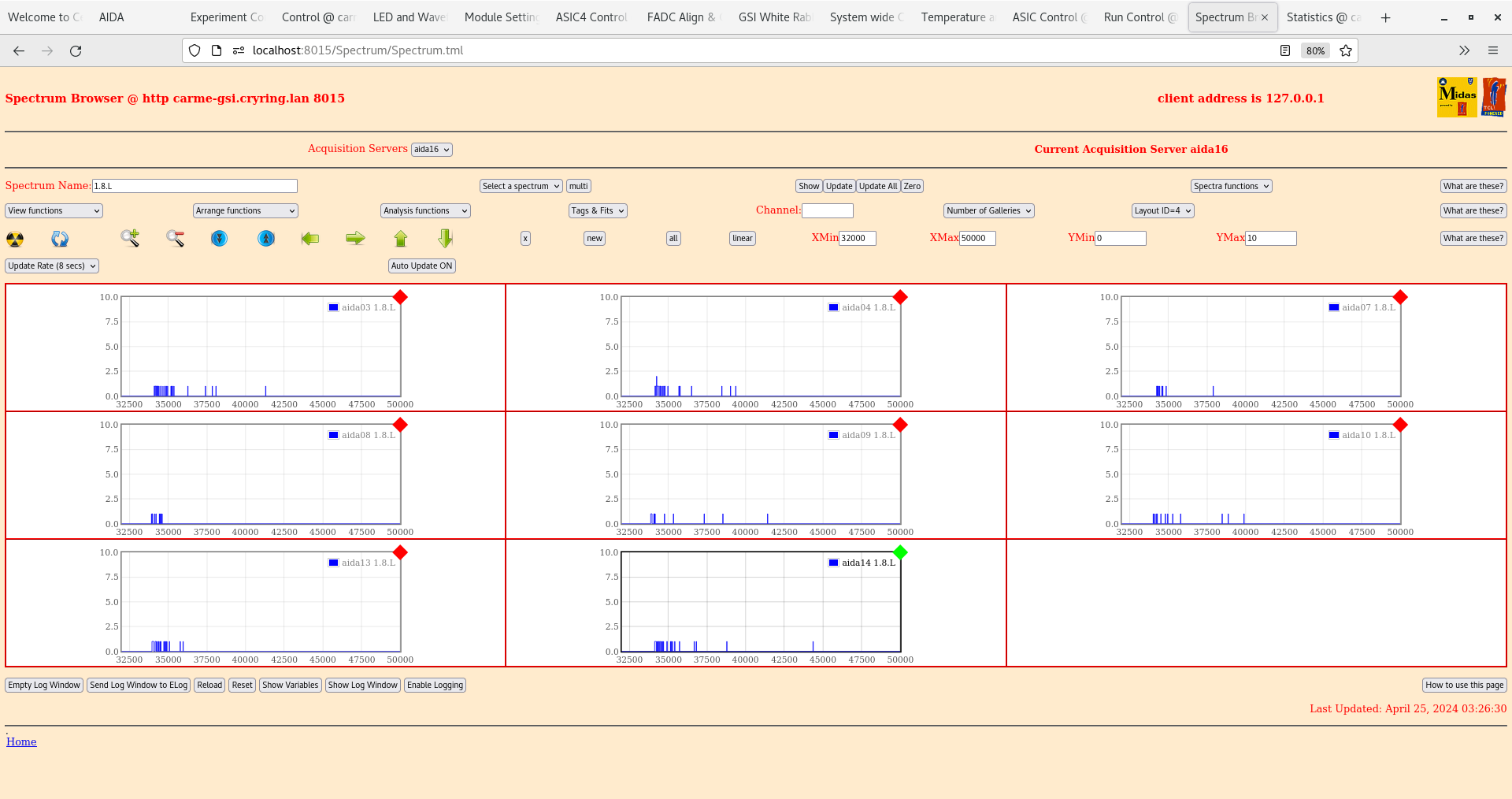
      per n+n FEE64 1.8.L spectra - attachment 4

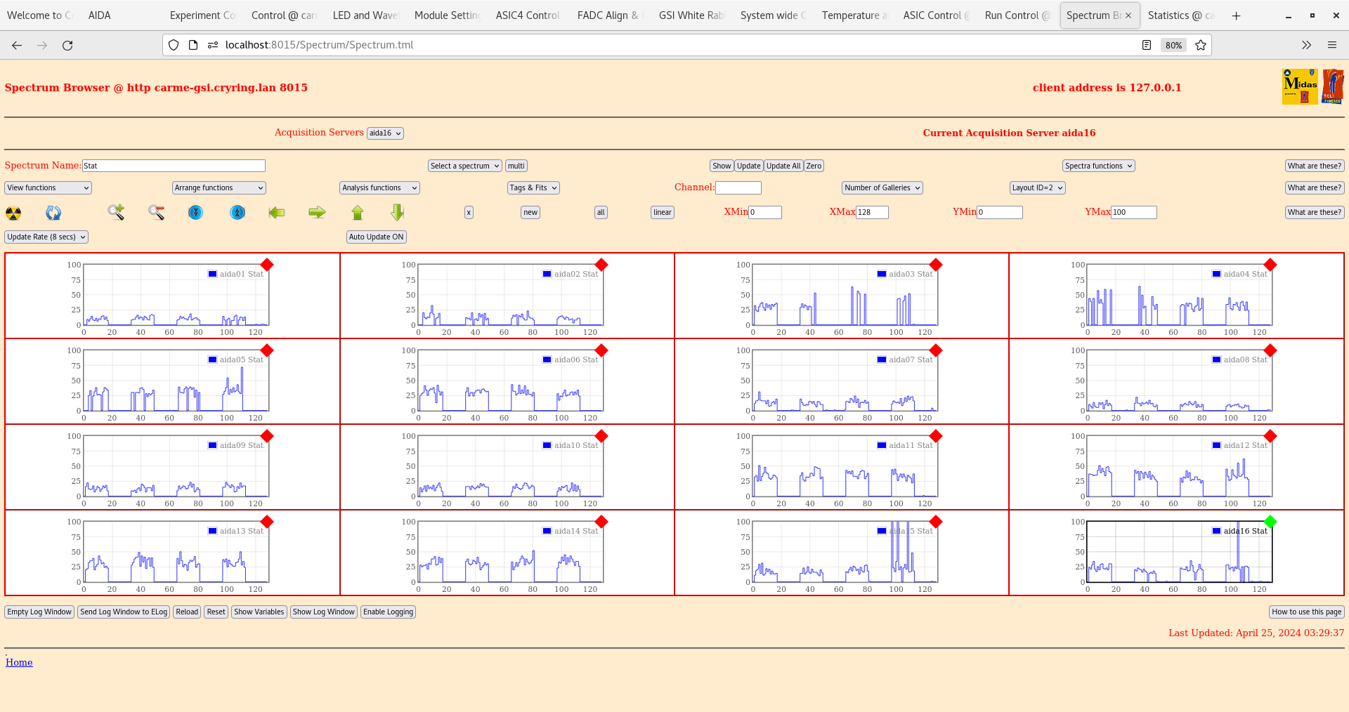
      per FEE64 Stat spectra - attachment 5

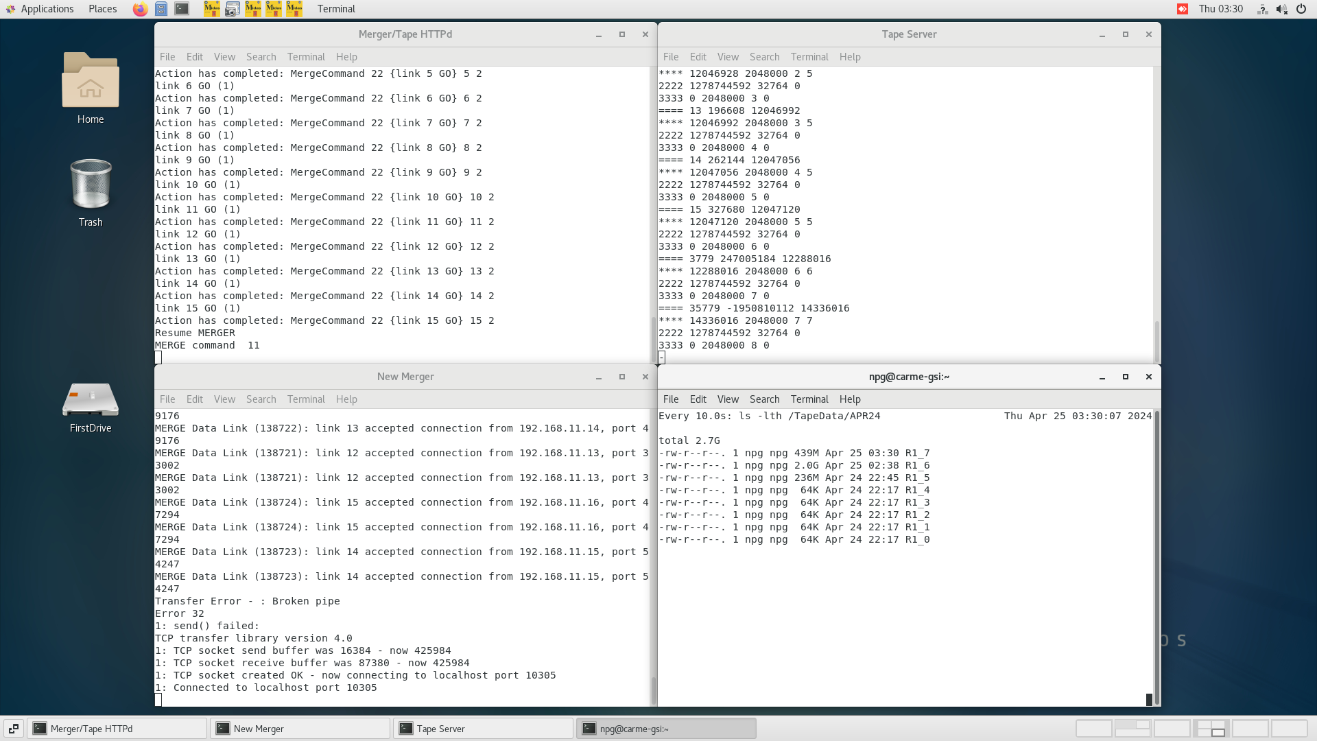
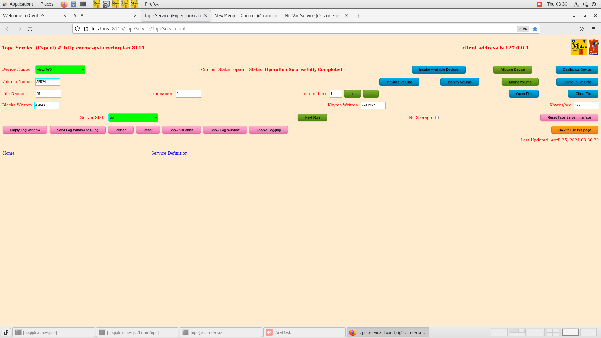
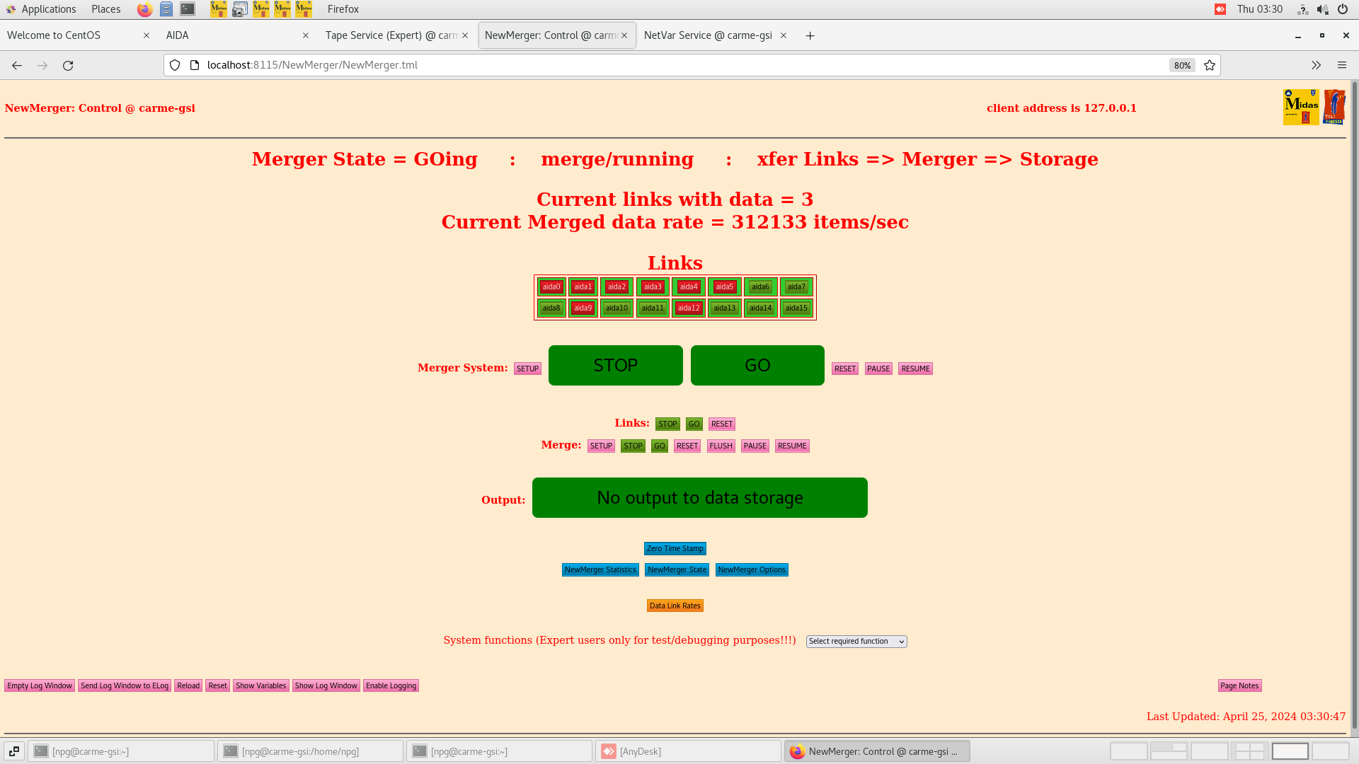
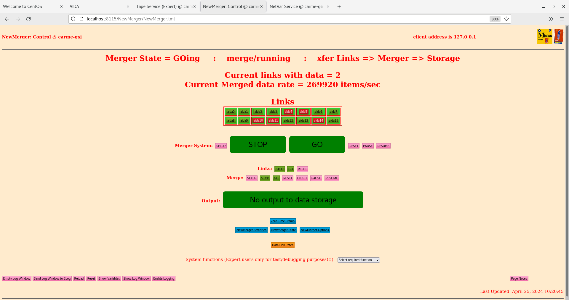
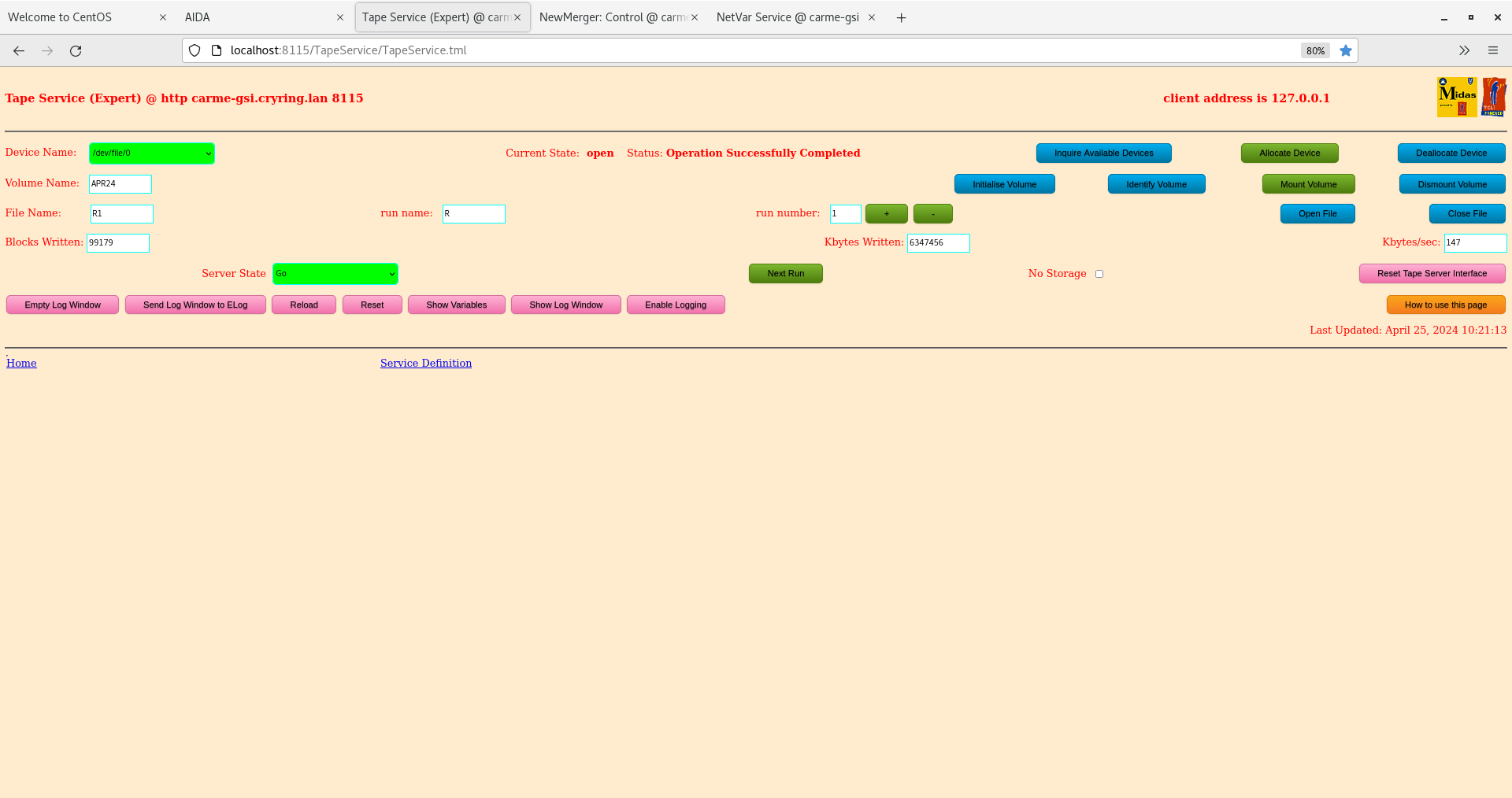
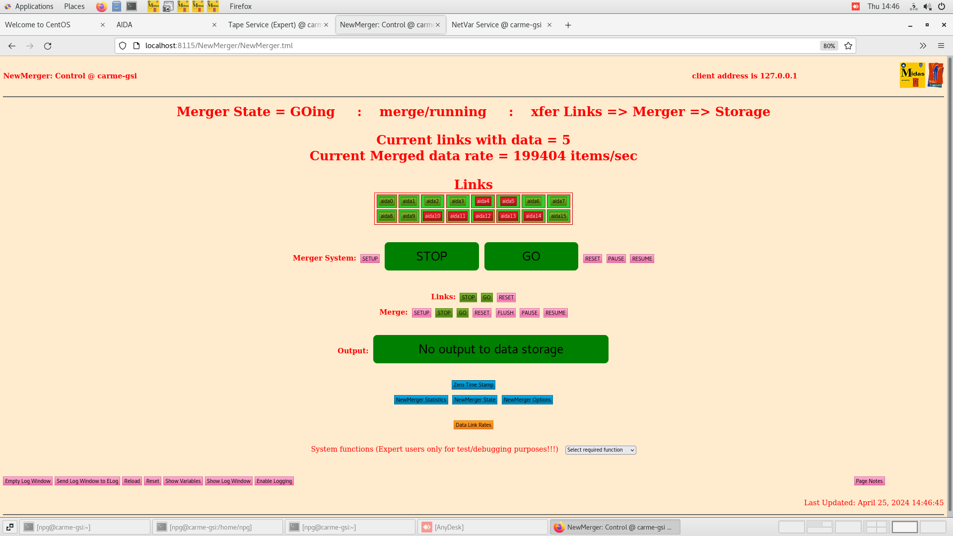
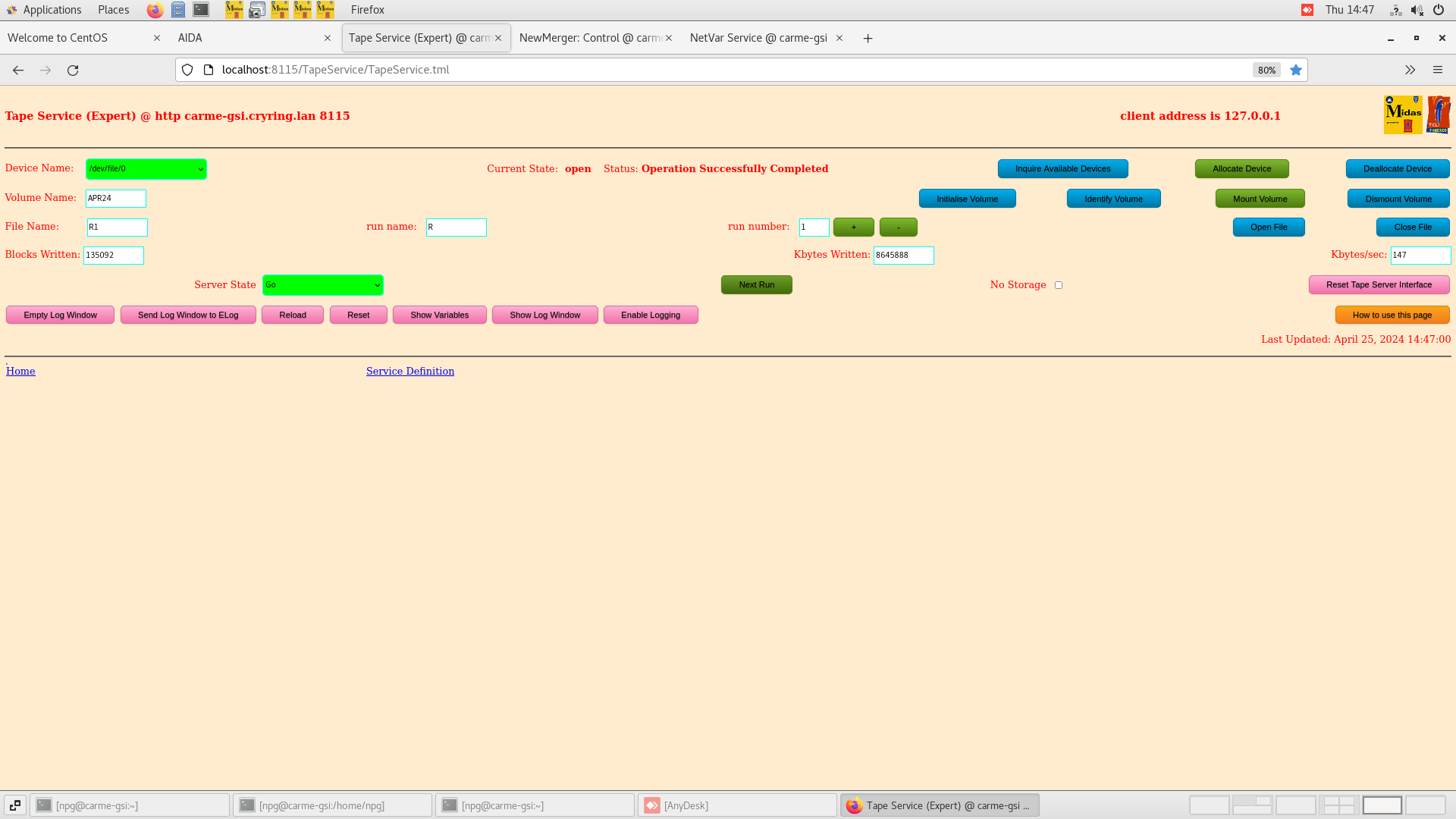
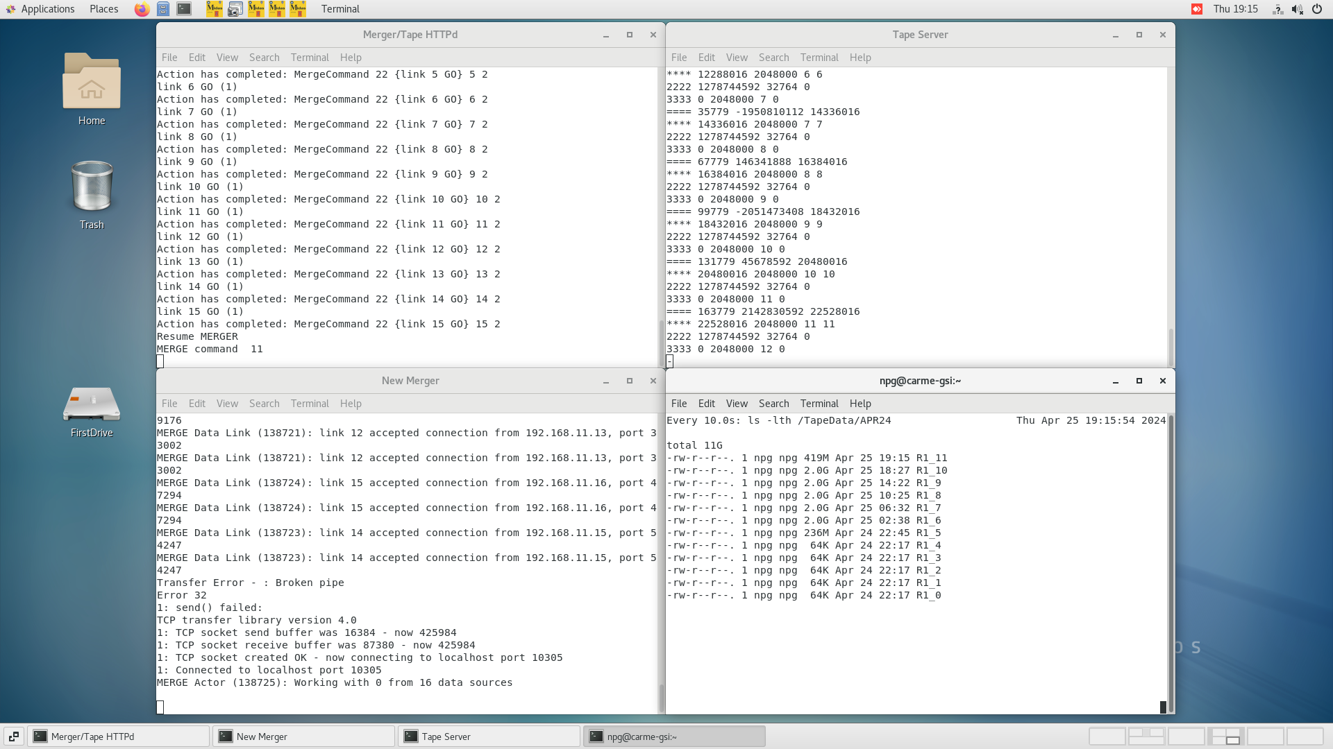
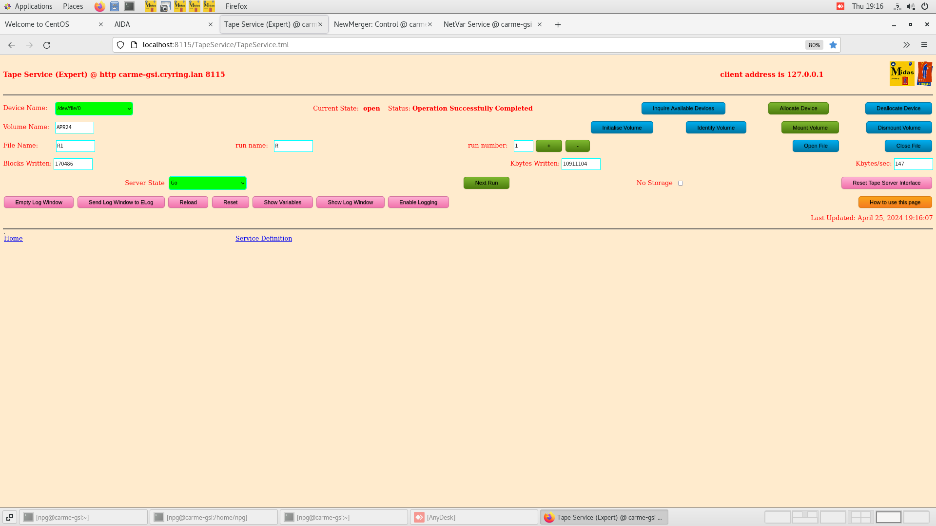
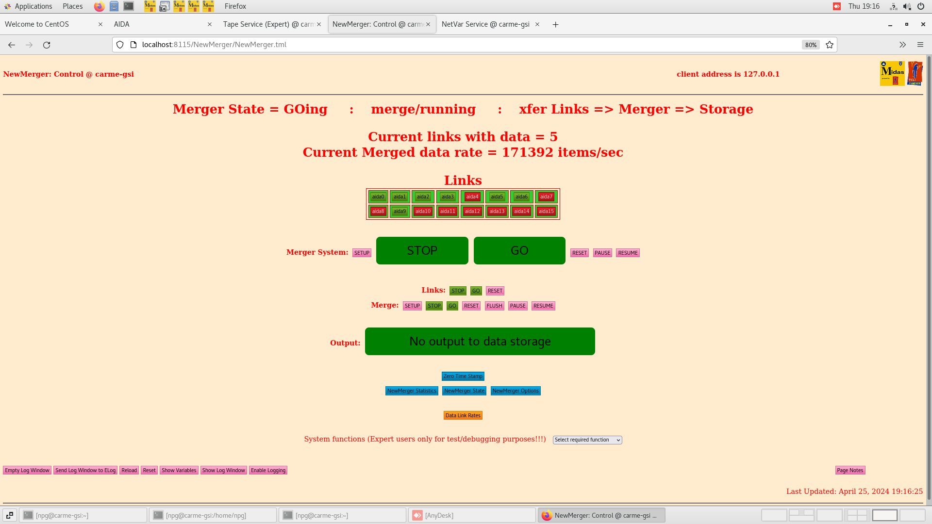
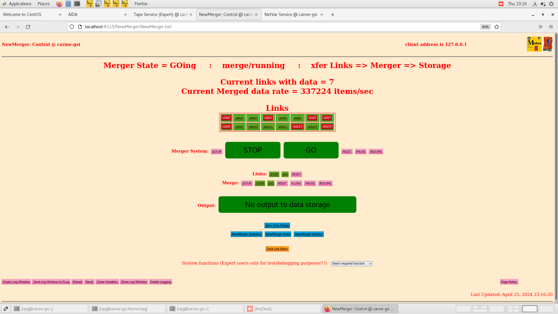
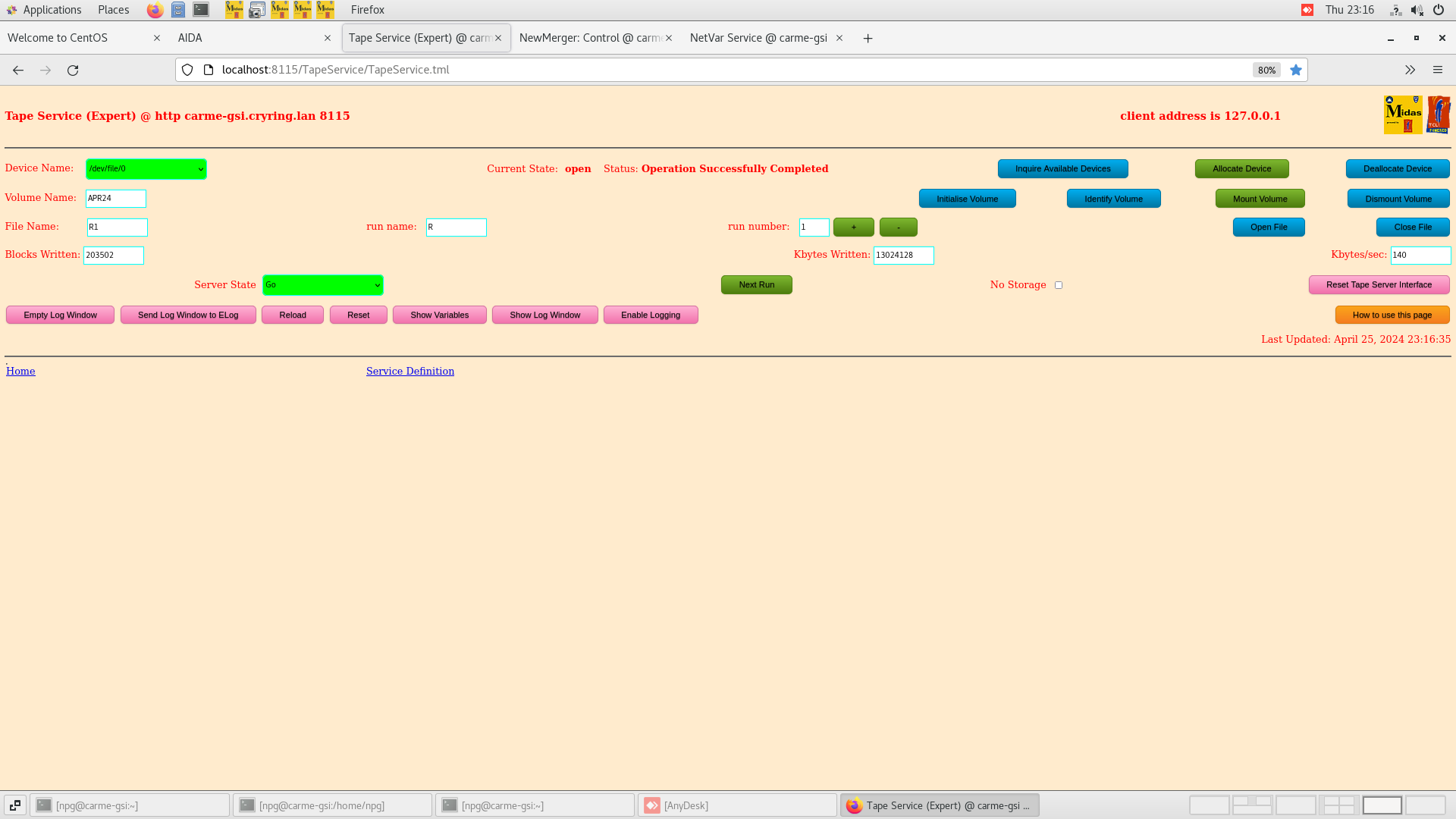
      Merger, TapeServer etc - attachments 6-8


10.19 DAQ continues - file APR24/R1_8

      DSSSD bias & leakage current OK - attachment 9
      ambient temperature 16.2 deg C

      FEE64 temperatures OK - attachment 10

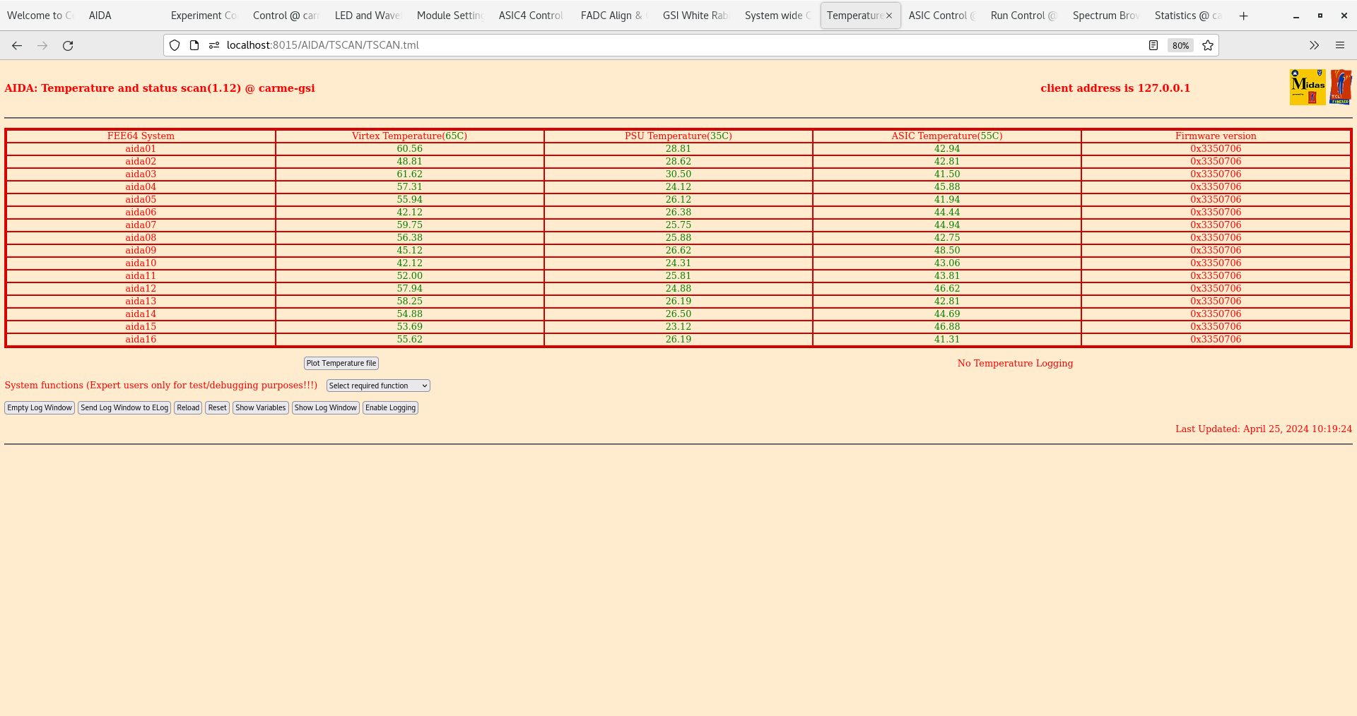
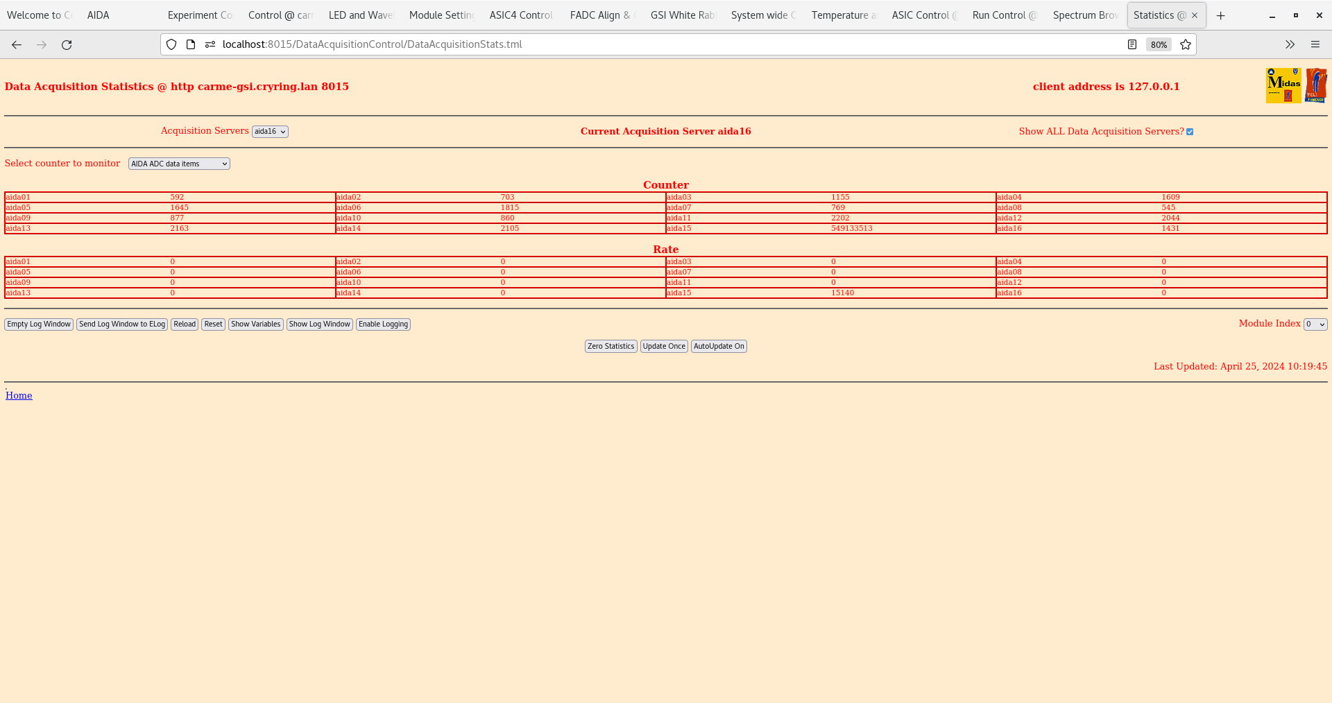
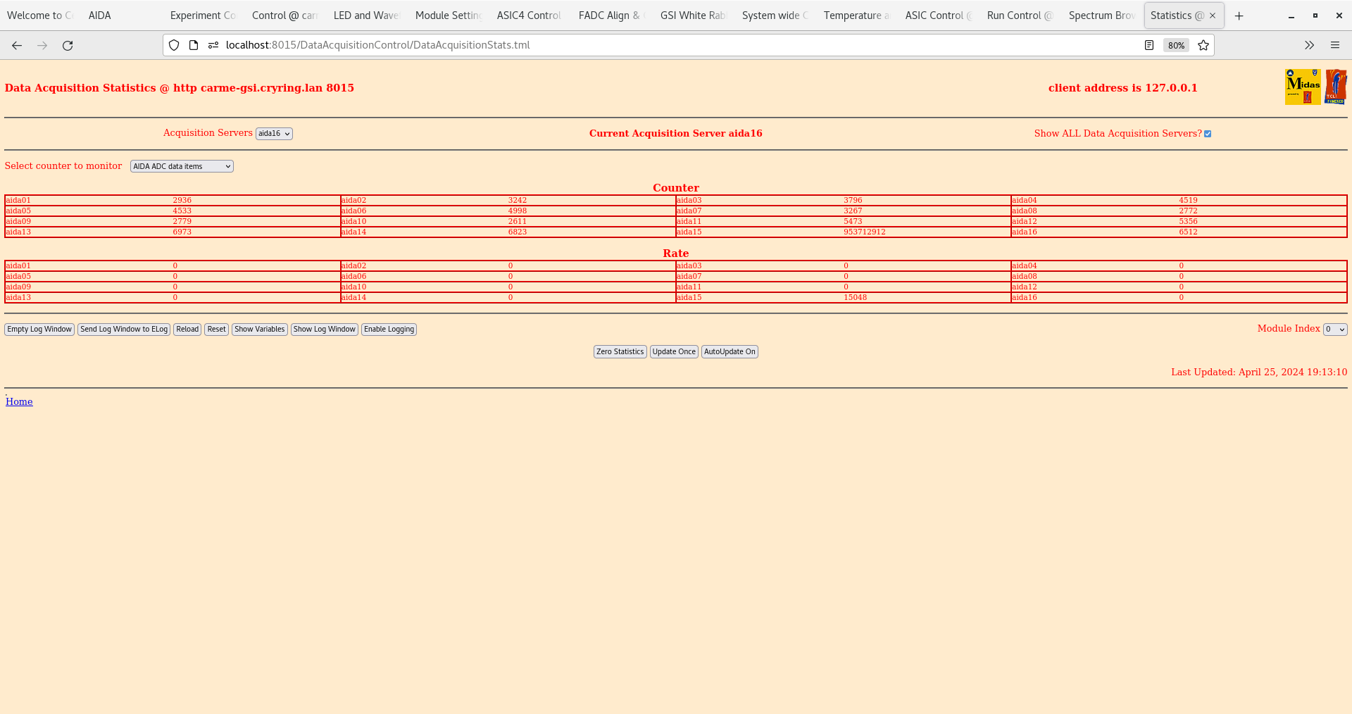
      ADC data item stats OK - attachment 11

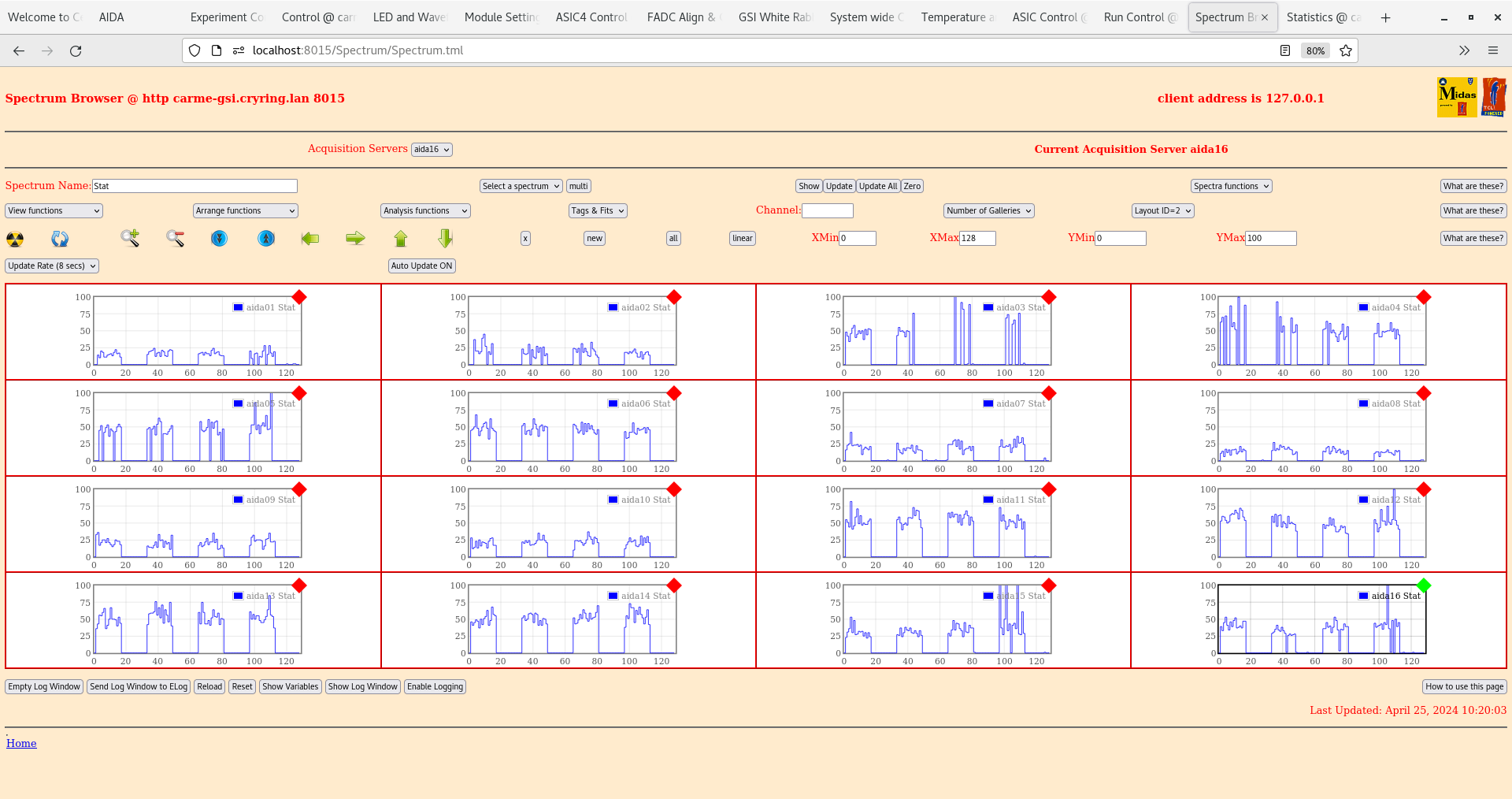
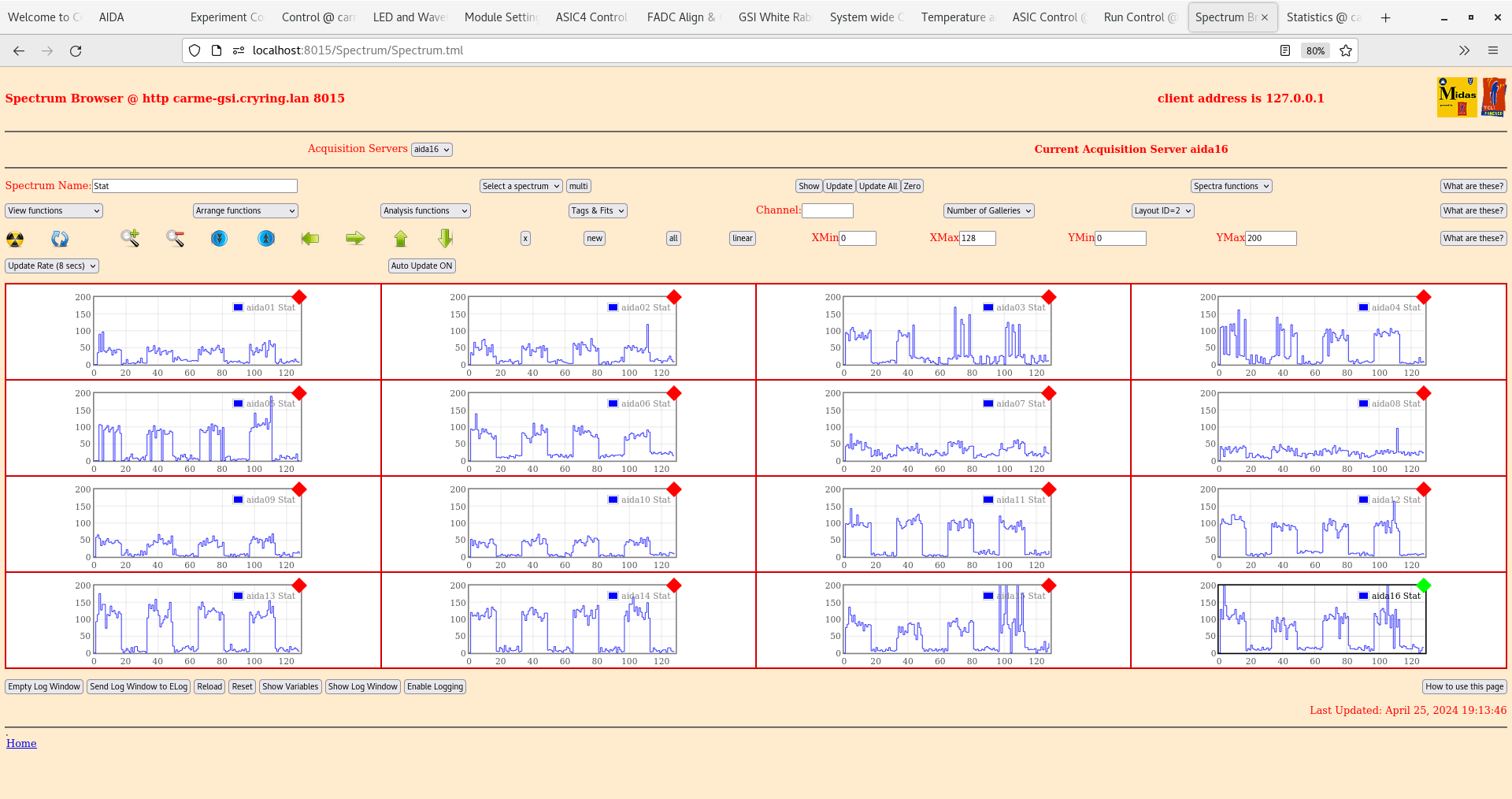
      per FEE64 Stat spectra - attachment 12

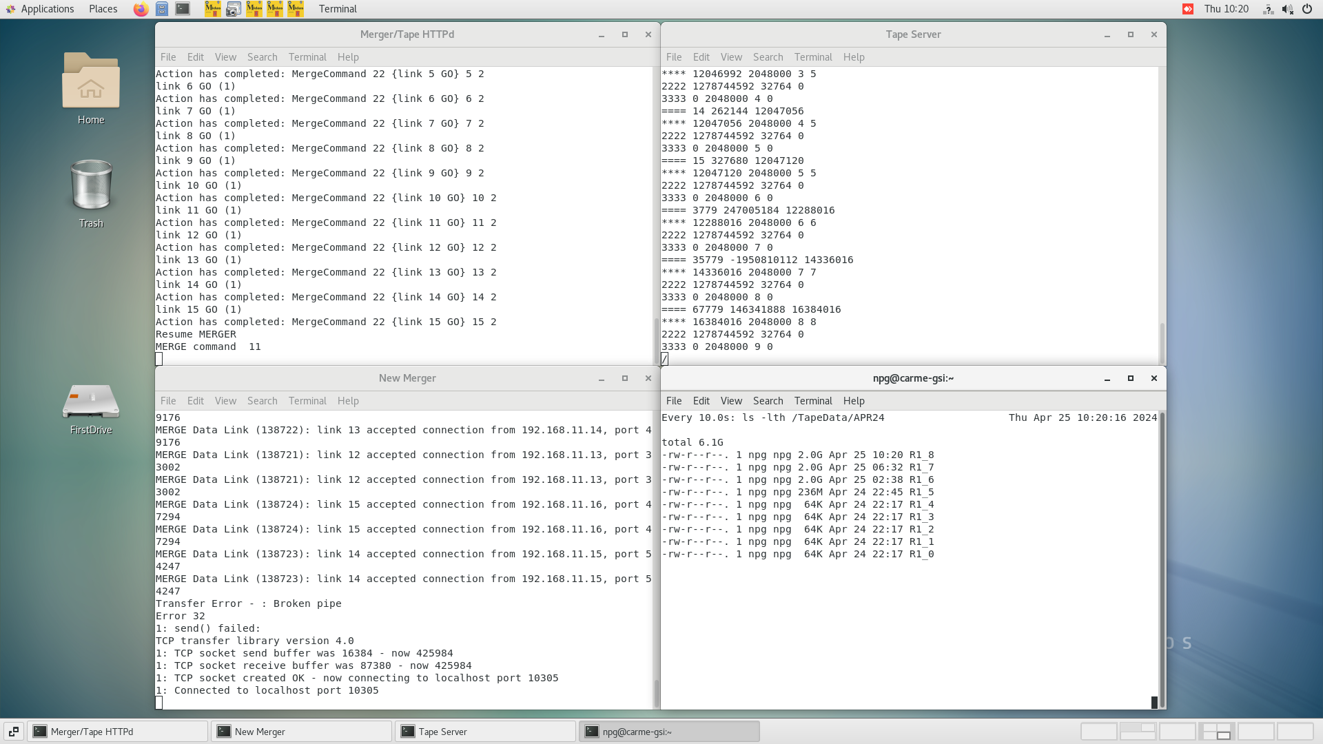
      Merger, TapeServer etc - attachments 13-15

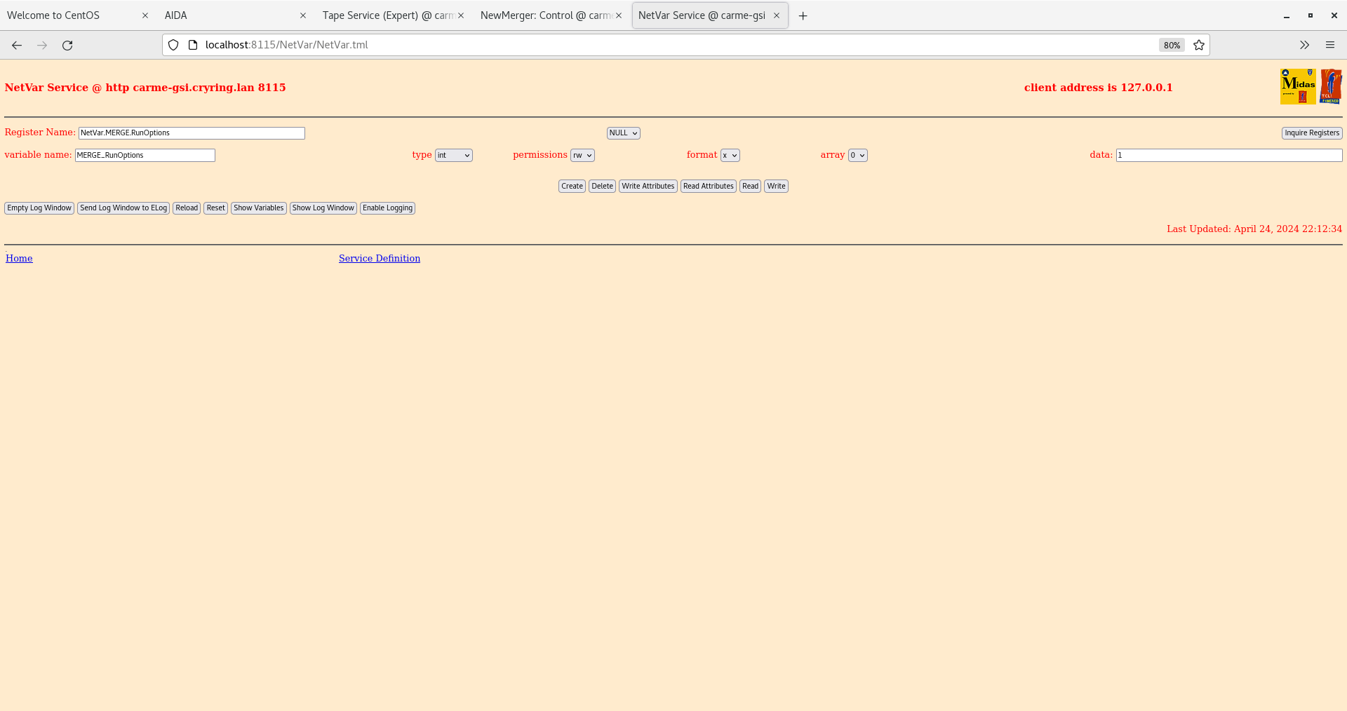
      NetVar merge variables - attachment 16


14.44 DAQ continues - file APR24/R1_10

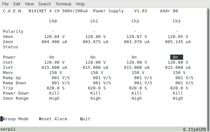
      DSSSD bias & leakage current OK - attachment 17
      ambient temperature 16.5 deg C

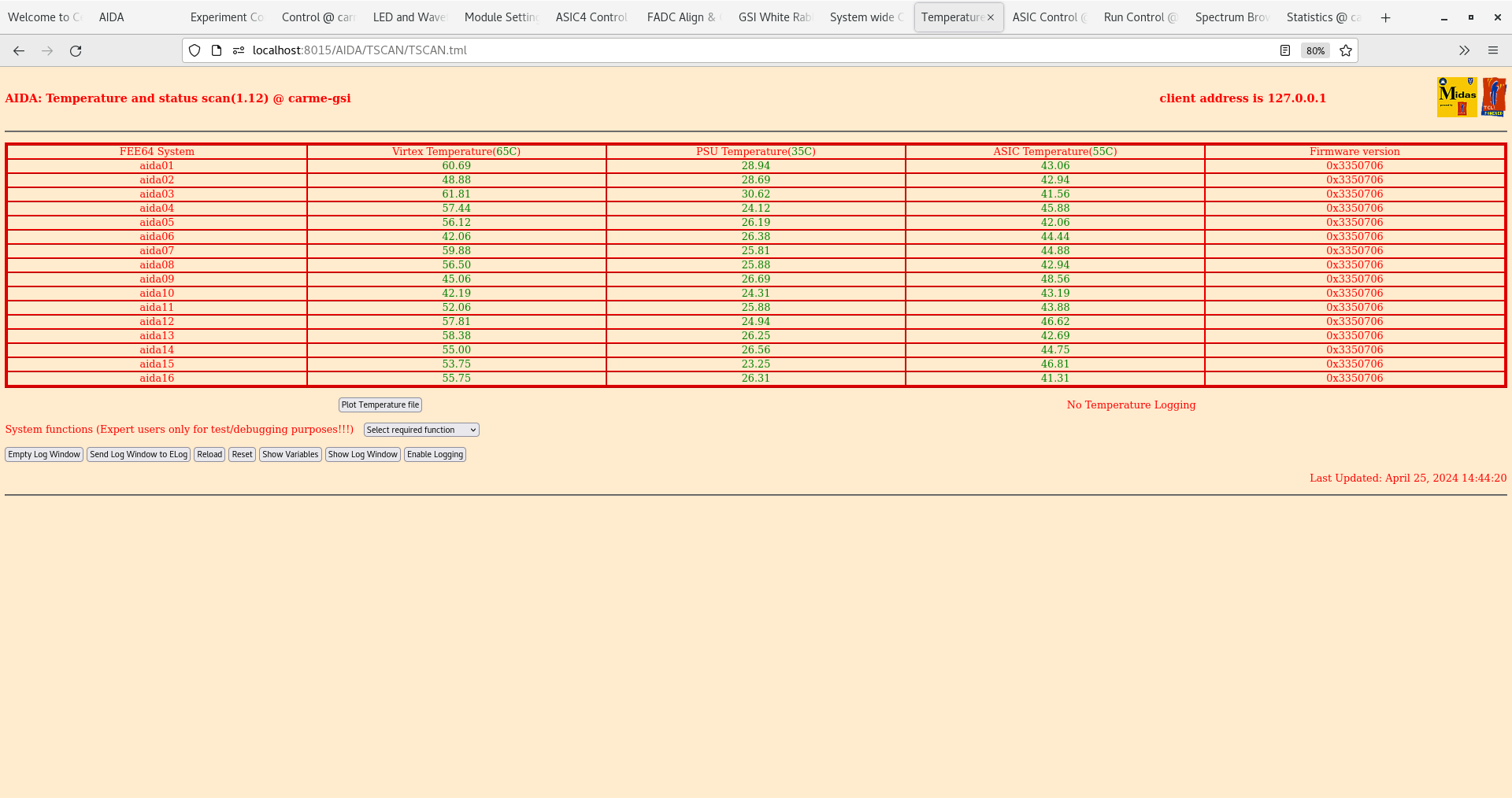
      FEE64 temperatures OK - attachment 18

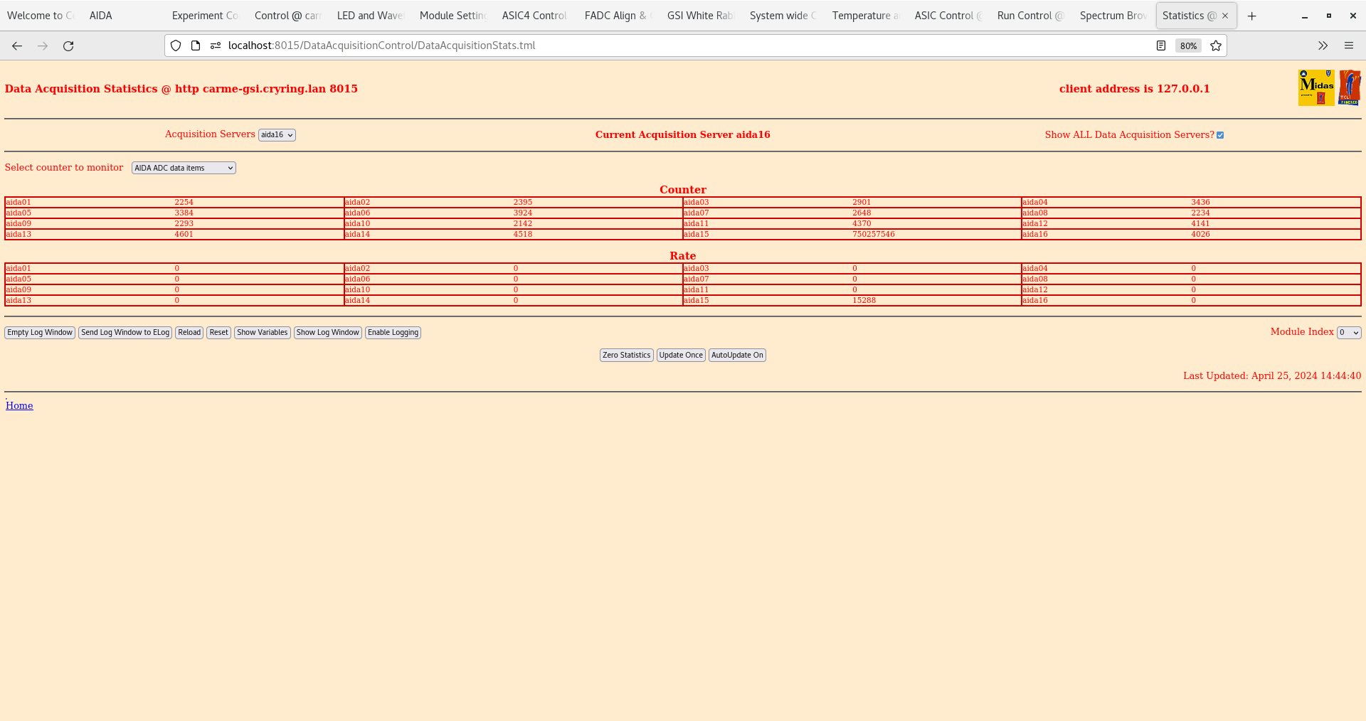
      ADC data item stats OK - attachment 19

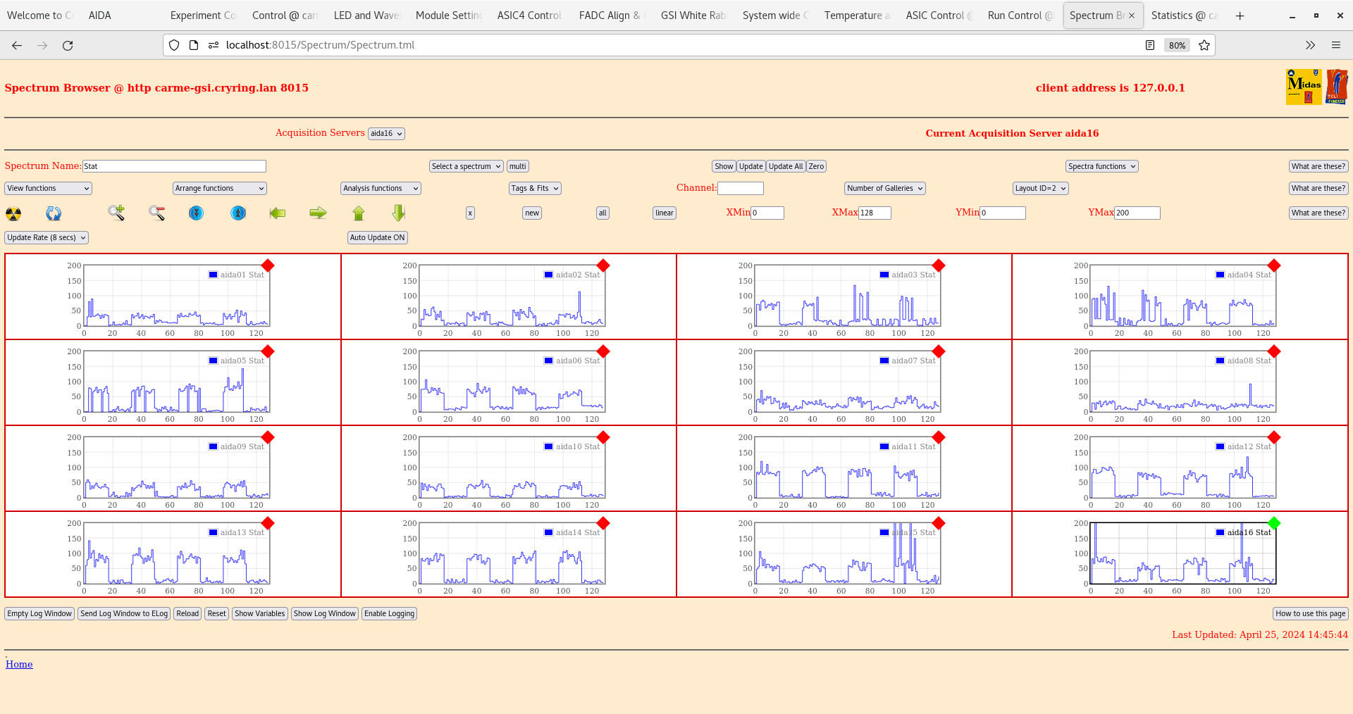
      per FEE64 Stat spectra - attachment 20
       some HEC data has appeared

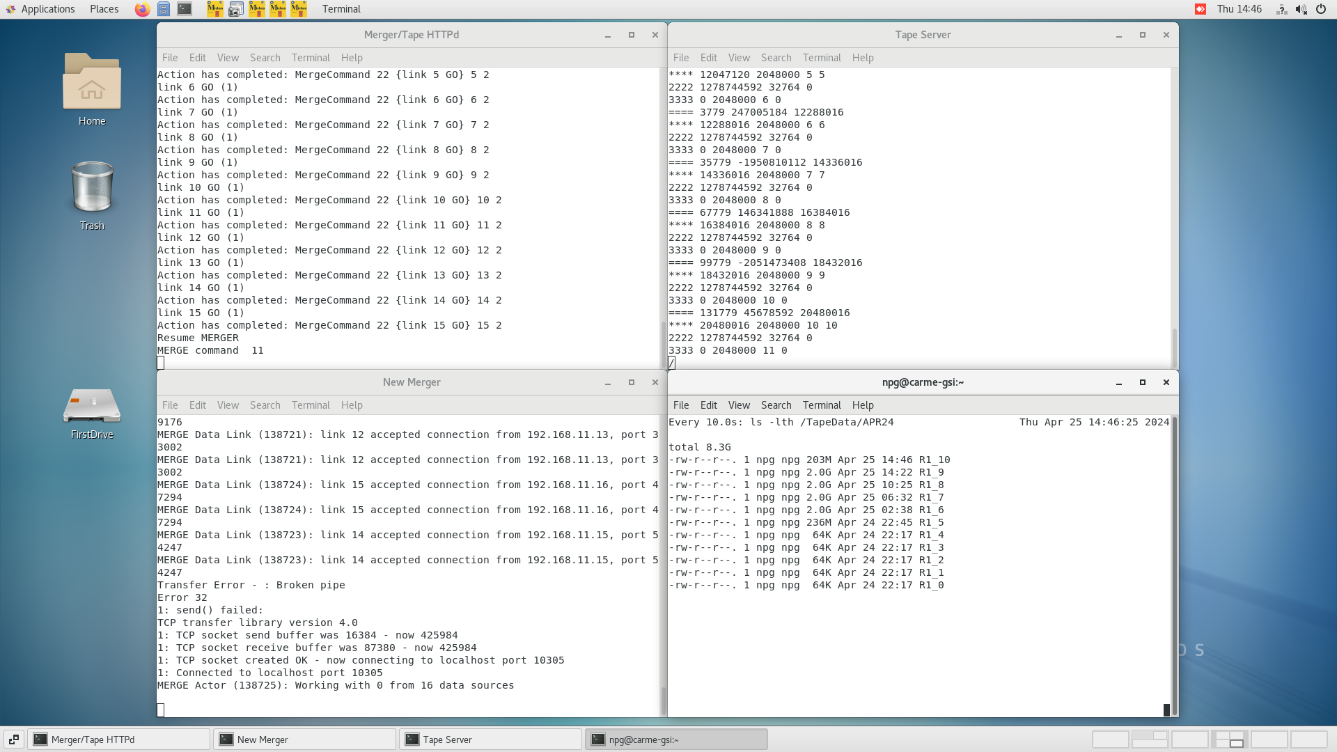
      Merger, TapeServer etc - attachments 21-23

19.12 DAQ continues - file APR24/R1_11

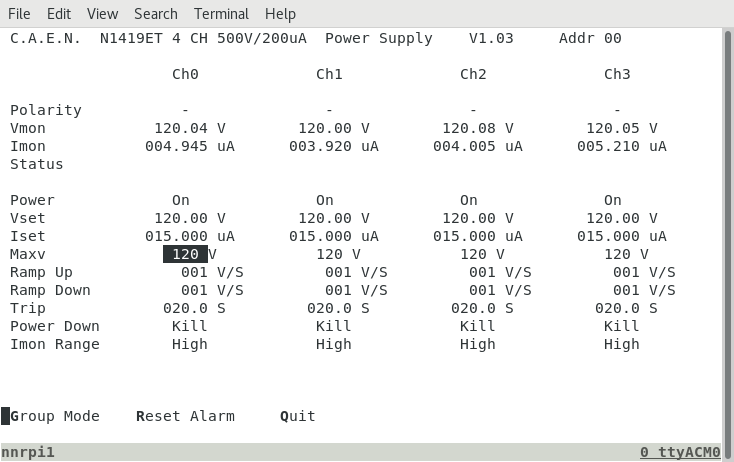
      DSSSD bias & leakage current OK - attachment 24
      ambient temperature 16.5 deg C

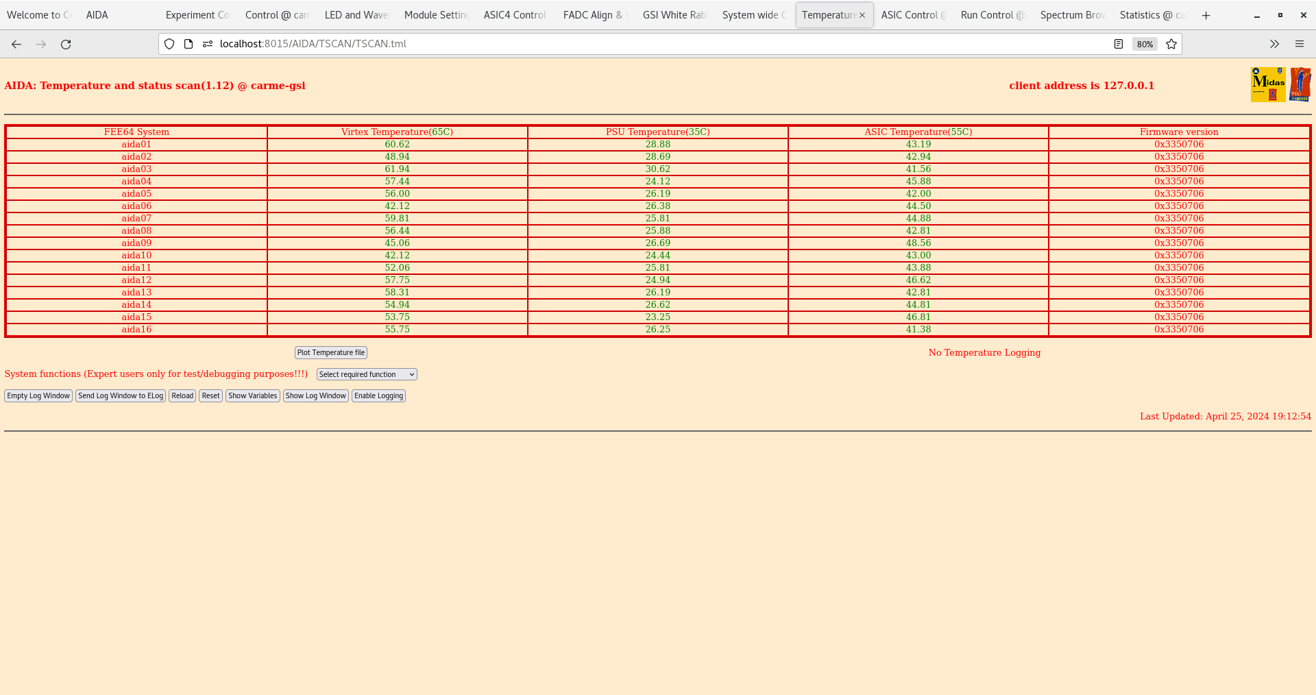
      FEE64 temperatures OK - attachment 25

      ADC data item stats OK - attachment 26

      per FEE64 Stat spectra - attachment 27

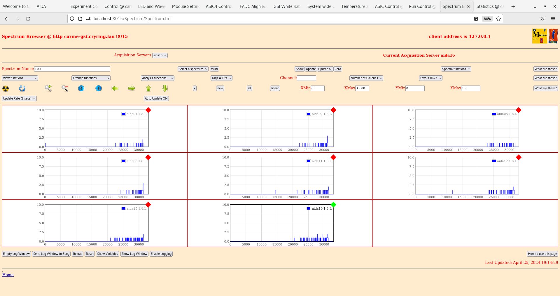
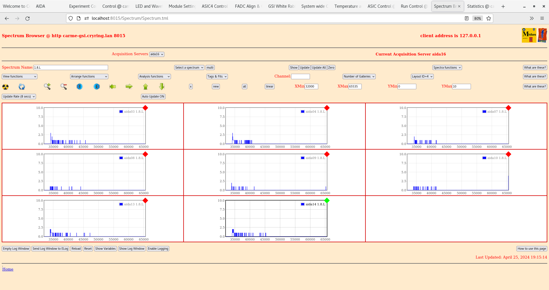
      per FEE64 1.8.L spectra - attachments 28-29

      Merger, TapeServer etc - attachments 30-32

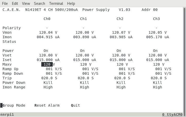
23.14 DAQ continues - file APR24/R1_12

      DSSSD bias & leakage current OK - attachment 33
      ambient temperature 16.1 deg C

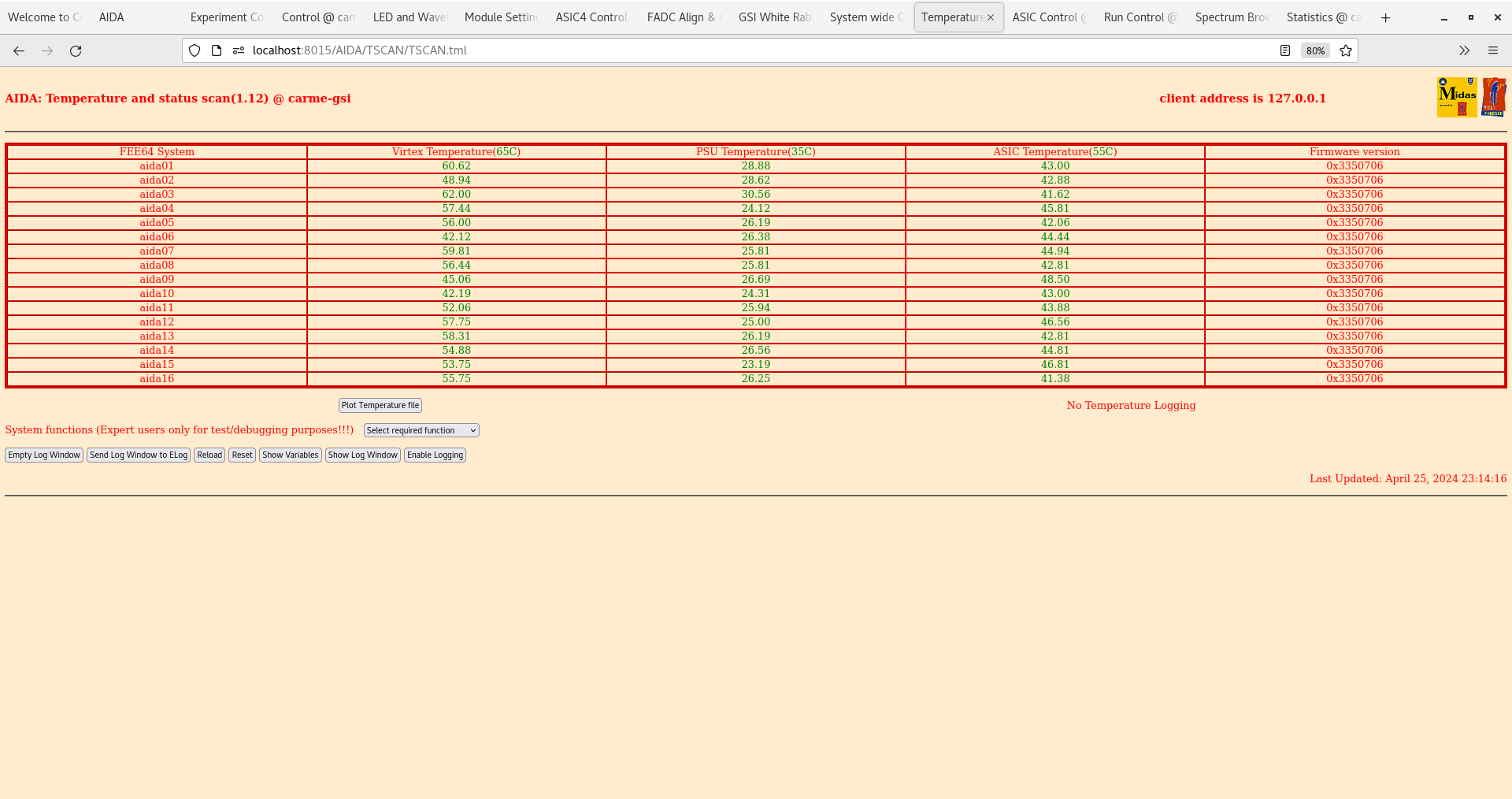
      FEE64 temperatures OK - attachment 34

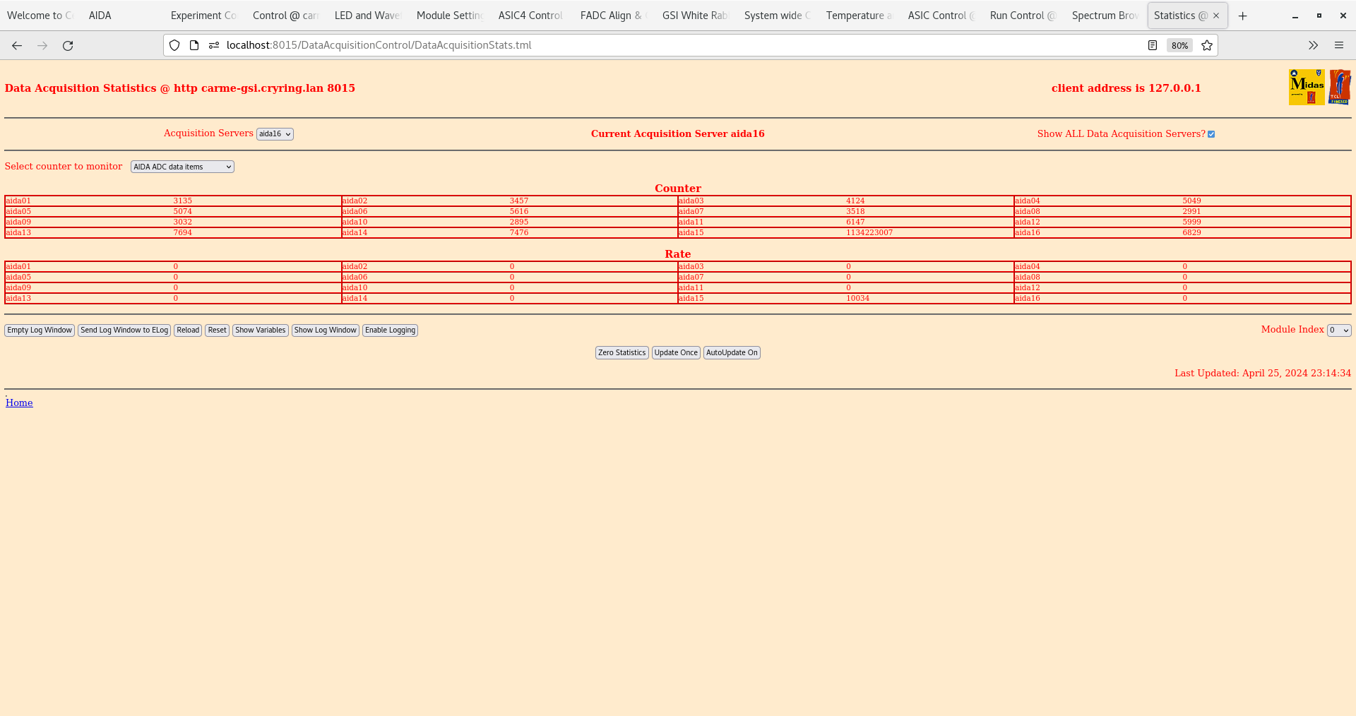
      ADC data item stats OK - attachment 35

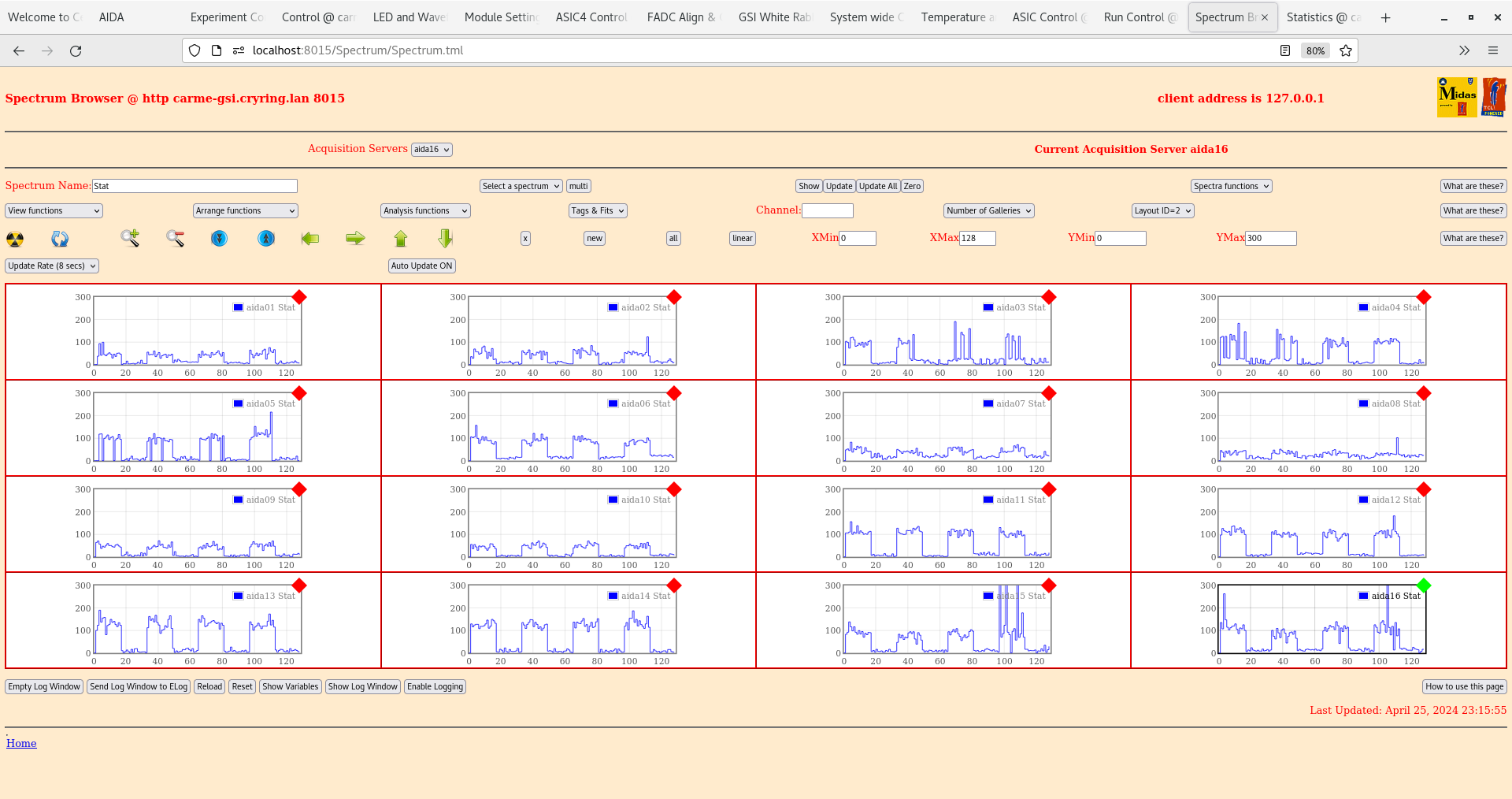
      per FEE64 Stat spectra - attachment 36

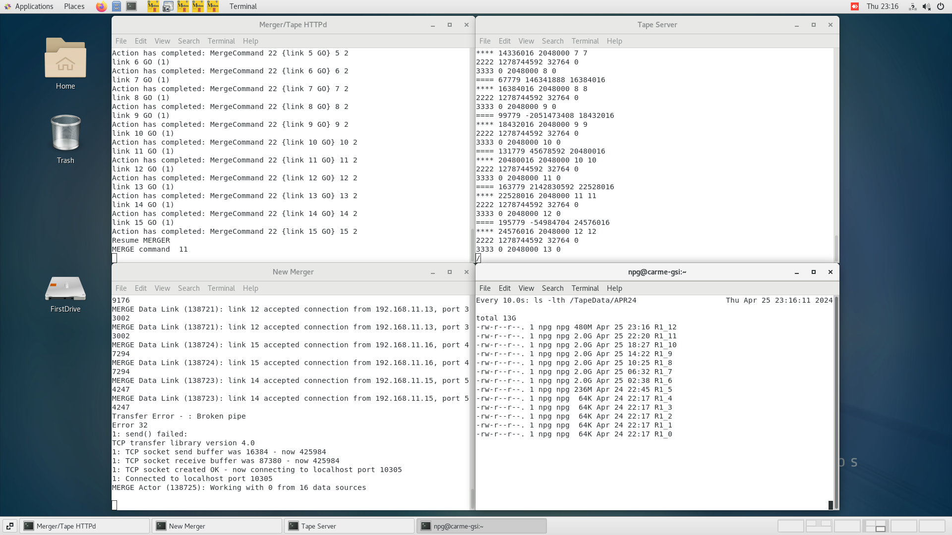
Merger, TapeServer etc - attachments 37-39 |
| Attachment 1: Screenshot_from_2024-04-25_03-26-58.png
|
|
| Attachment 2: Screenshot_from_2024-04-25_03-27-48.png
|
|
| Attachment 3: Screenshot_from_2024-04-25_03-28-19.png
|
|
| Attachment 4: Screenshot_from_2024-04-25_03-28-41.png
|
|
| Attachment 5: Screenshot_from_2024-04-25_03-32-43.png
|
|
| Attachment 6: Screenshot_from_2024-04-25_03-30-13.png
|
|
| Attachment 7: Screenshot_from_2024-04-25_03-30-37.png
|
|
| Attachment 8: Screenshot_from_2024-04-25_03-30-55.png
|
|
| Attachment 9: Screenshot_from_2024-04-25_10-19-09.png
|
|
| Attachment 10: Screenshot_from_2024-04-25_10-19-31.png
|
|
| Attachment 11: Screenshot_from_2024-04-25_10-19-54.png
|
|
| Attachment 12: Screenshot_from_2024-04-25_10-20-14.png
|
|
| Attachment 13: Screenshot_from_2024-04-25_10-20-26.png
|
|
| Attachment 14: Screenshot_from_2024-04-25_10-20-53.png
|
|
| Attachment 15: Screenshot_from_2024-04-25_10-21-22.png
|
|
| Attachment 16: Screenshot_from_2024-04-25_10-21-45.png
|
|
| Attachment 17: Screenshot_from_2024-04-25_14-44-05.png
|
|
| Attachment 18: Screenshot_from_2024-04-25_14-44-29.png
|
|
| Attachment 19: Screenshot_from_2024-04-25_14-44-49.png
|
|
| Attachment 20: Screenshot_from_2024-04-25_14-45-51.png
|
|
| Attachment 21: Screenshot_from_2024-04-25_14-46-35.png
|
|
| Attachment 22: Screenshot_from_2024-04-25_14-46-53.png
|
|
| Attachment 23: Screenshot_from_2024-04-25_14-47-05.png
|
|
| Attachment 24: Screenshot_from_2024-04-25_19-12-30.png
|
|
| Attachment 25: Screenshot_from_2024-04-25_19-13-01.png
|
|
| Attachment 26: Screenshot_from_2024-04-25_19-13-39.png
|
|
| Attachment 27: Screenshot_from_2024-04-25_19-14-02.png
|
|
| Attachment 28: Screenshot_from_2024-04-25_19-14-40.png
|
|
| Attachment 29: Screenshot_from_2024-04-25_19-15-24.png
|
|
| Attachment 30: Screenshot_from_2024-04-25_19-15-58.png
|
|
| Attachment 31: Screenshot_from_2024-04-25_19-16-12.png
|
|
| Attachment 32: Screenshot_from_2024-04-25_19-16-30.png
|
|
| Attachment 33: Screenshot_from_2024-04-25_23-14-01.png
|
|
| Attachment 34: Screenshot_from_2024-04-25_23-14-23.png
|
|
| Attachment 35: Screenshot_from_2024-04-25_23-14-41.png
|
|
| Attachment 36: Screenshot_from_2024-04-25_23-16-04.png
|
|
| Attachment 37: Screenshot_from_2024-04-25_23-16-12.png
|
|
| Attachment 38: Screenshot_from_2024-04-25_23-16-25.png
|
|
| Attachment 39: Screenshot_from_2024-04-25_23-16-42.png
|
|
|
20
|
Thu Sep 24 10:04:58 2020 |
JM, TD | Thursday 24 September |
Following overnight pumping by Leybold turbo pump

09.12 6.26e-8mbar, 2.8e-6mbar (RGA station), leak rate 5e-12 mbar.l/s

09:52 6.08e-8mbar, 2.8e-6mbar (RGA station), leak rate 8e-12 mbar.l/s

10.10 6.02e-8mbar, 2.8e-6mbar (RGA station), leak rate 8.5e-12mbar.l/s
KM says leak cart currently isolated CARME chamber + RGA cart - no He
has been used around chamber this week so figure represents noise.

10.36 5.94e-8mbar, 2.8e-6mbar (RGA station), leak rate 4.7e-12 mbar.l/s

10.40 KM isolated RGA station (@RGA station) from CARME chamber to replace current RGA (FC sensor) with a more sensitive RGA (with multiplier + FC sensor)

CARME vacuum pressure (with no backing) will rise somewhat during this process

11.17 1.35e-7mbar

11.20 New RGA install complete, backing line opened, CARME pressure recovers in < 10s to 5.83e-8mbar

14.08 5.59e-8mbar, 2.7e-6mbar (RGA station), leak cart disconnected (by KM)

Cables for neg and neg ion pumps connected with cables trailed out of the octagon through back and front of the octagon. Neg-ion pump connectors are labelled with Kapton
tape to prevent confusion with neg connectors. Baking jacket has been partially constructed and will be completed tomorrow. |
| Attachment 1: 20200924_152852.jpg
|

|
| Attachment 2: Photos.zip
|
|
28
|
Thu Oct 22 10:39:40 2020 |
TD | Thursday 22 October |
10.40

CARME chamber 2.84e-08mbar
Backing 1.2e-7mbar (Edwards vacuum cart w/RGA)

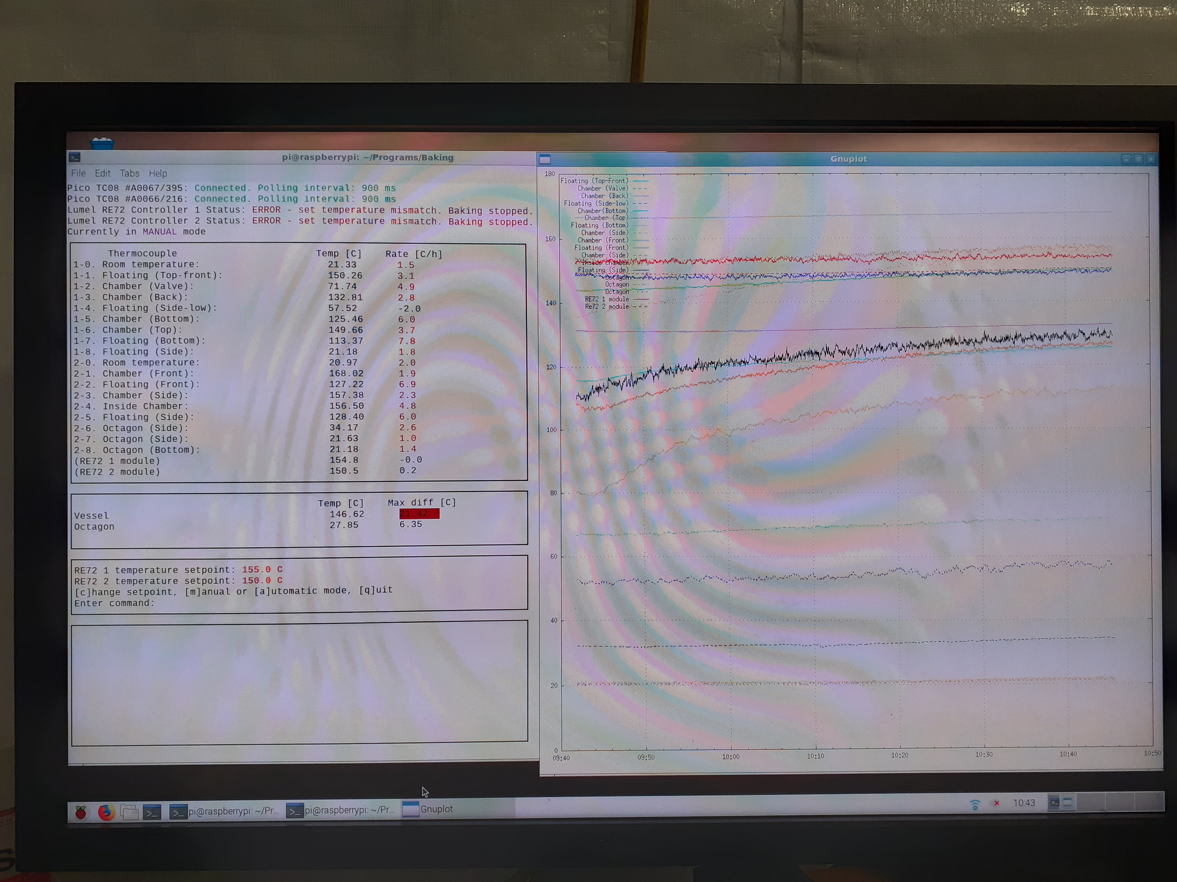
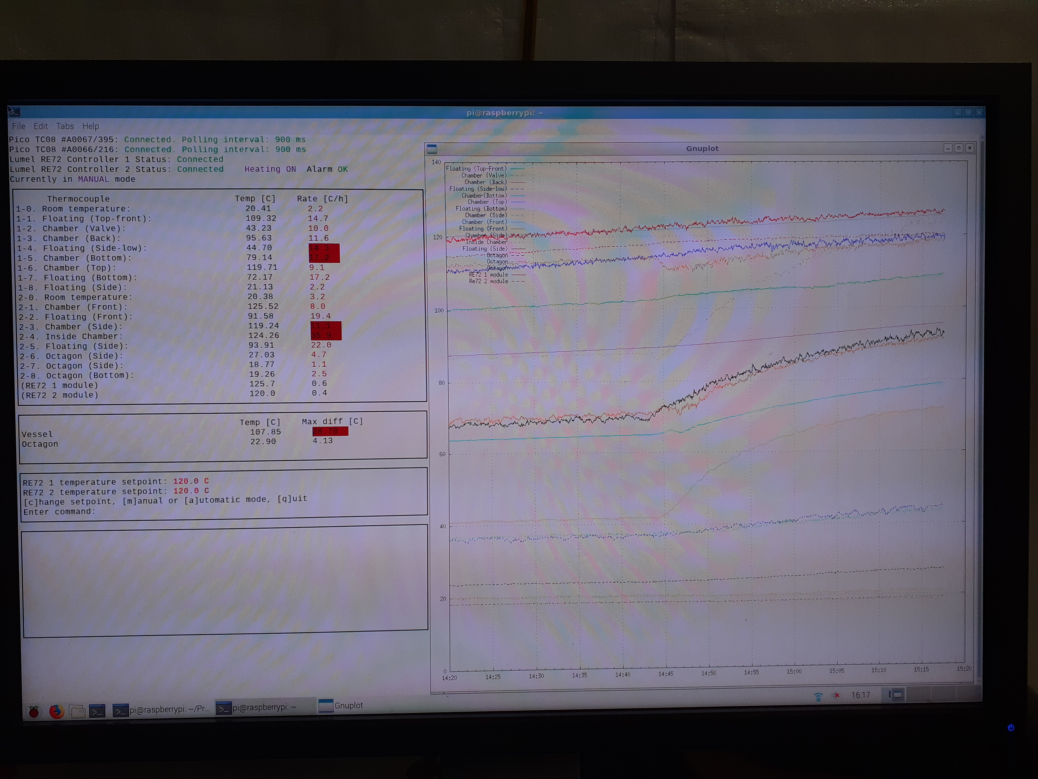
CARME temps - see attachment 1
vessel 146.62 deg C max diff 21.42 deg C
octagon 27.85 deg C max diff 6.35

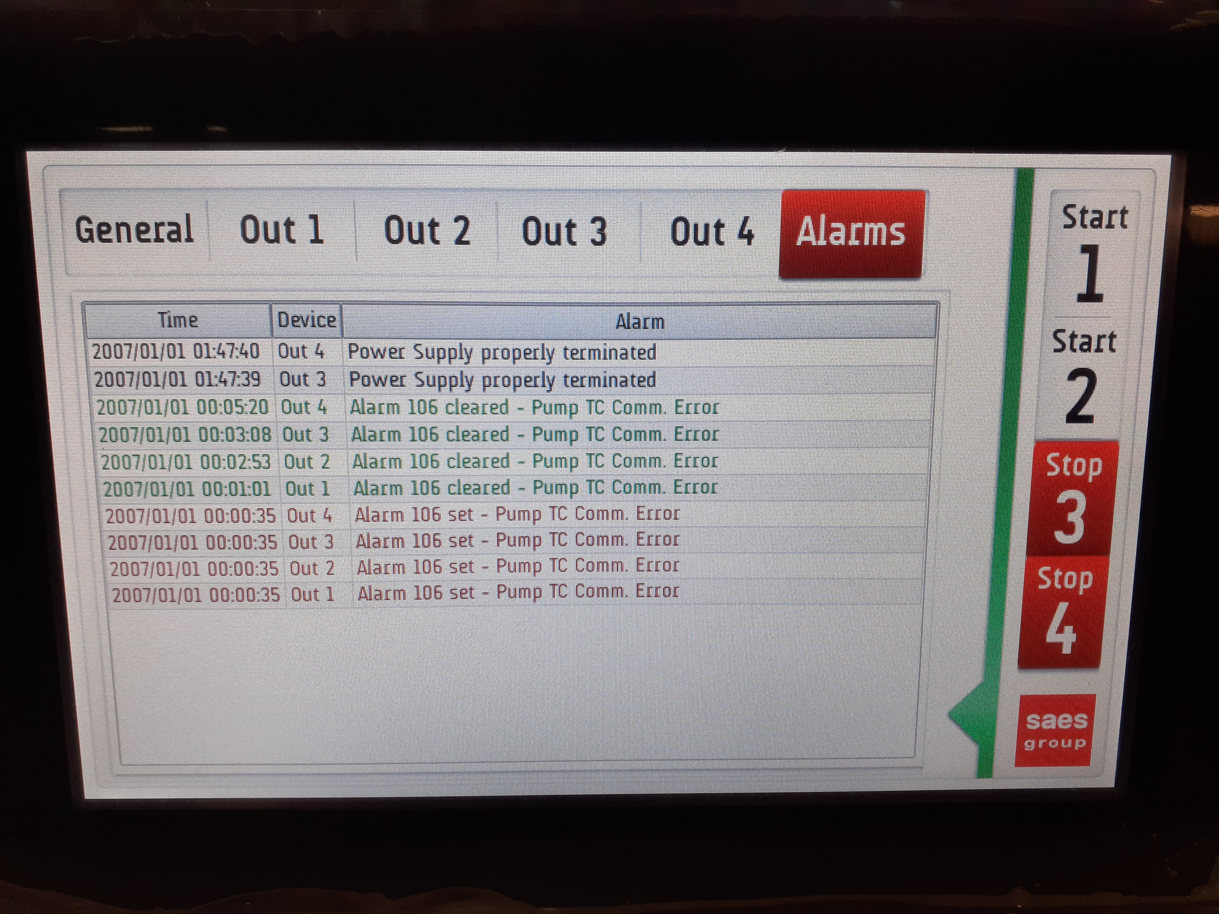
SAES HV power modules - see attachments 2-12

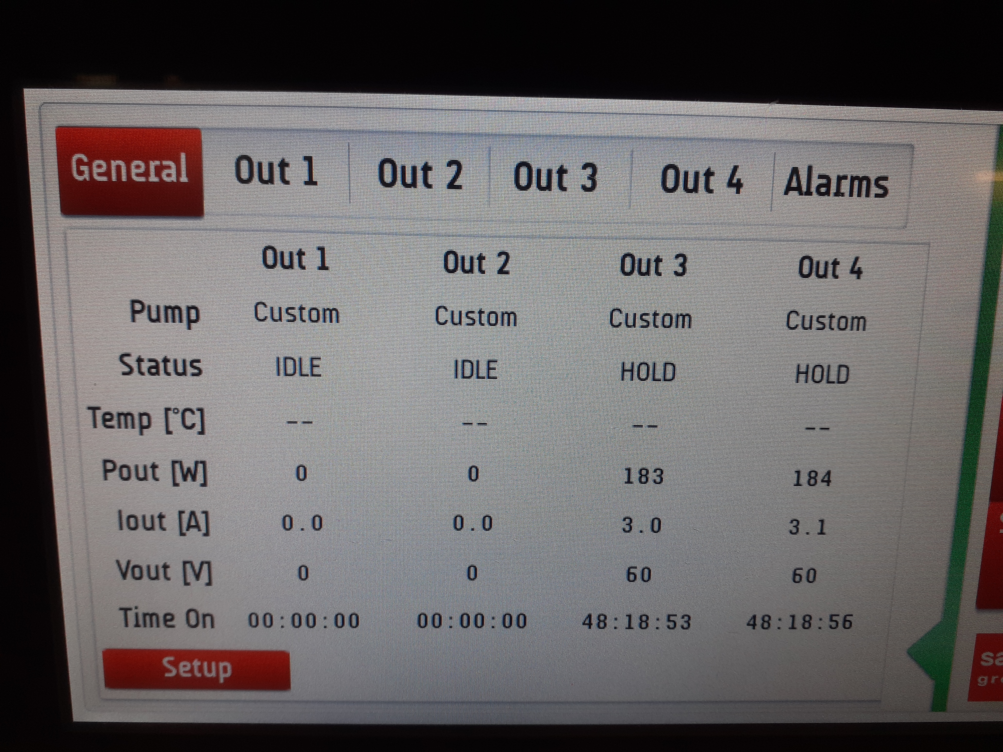
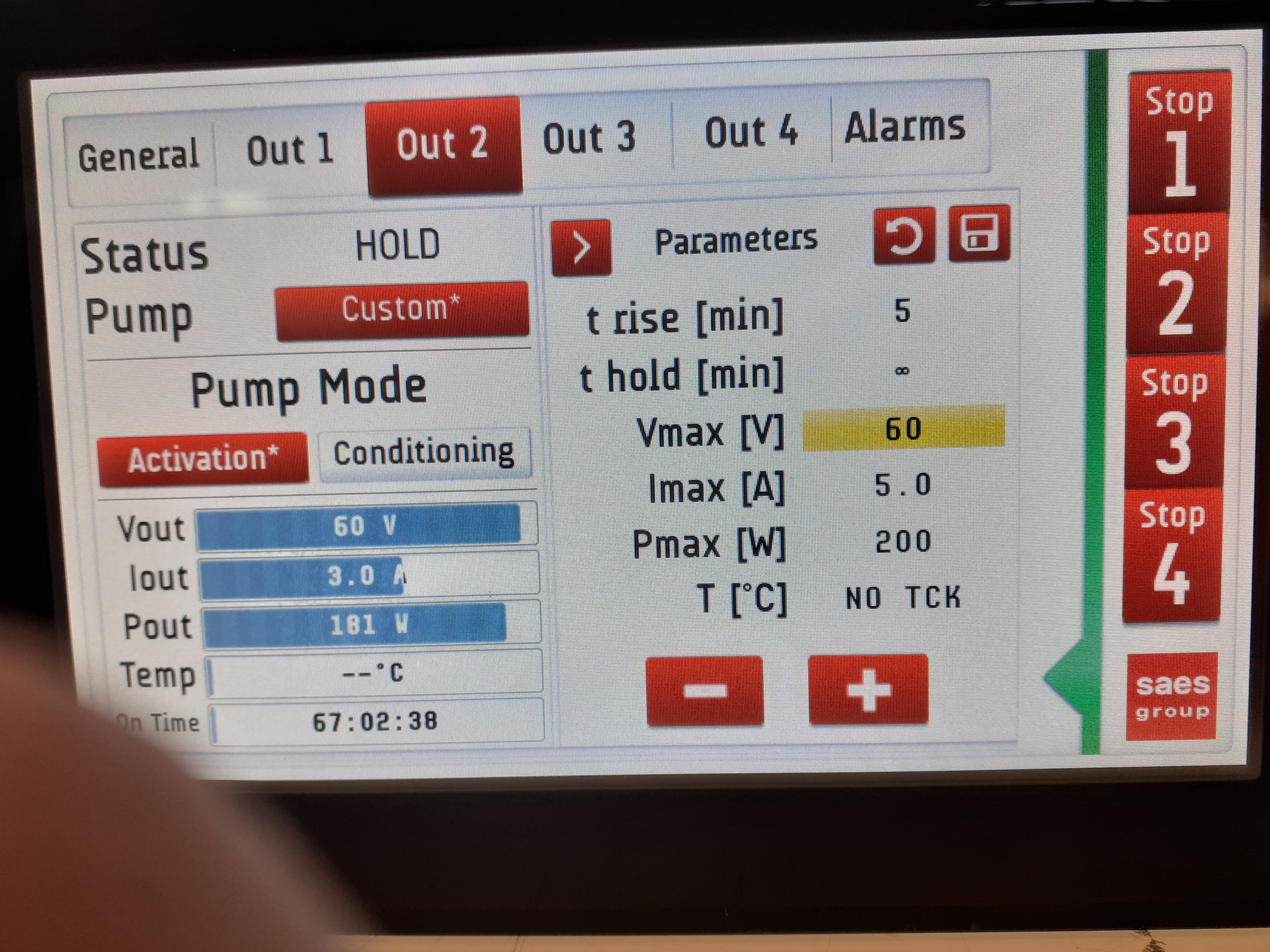
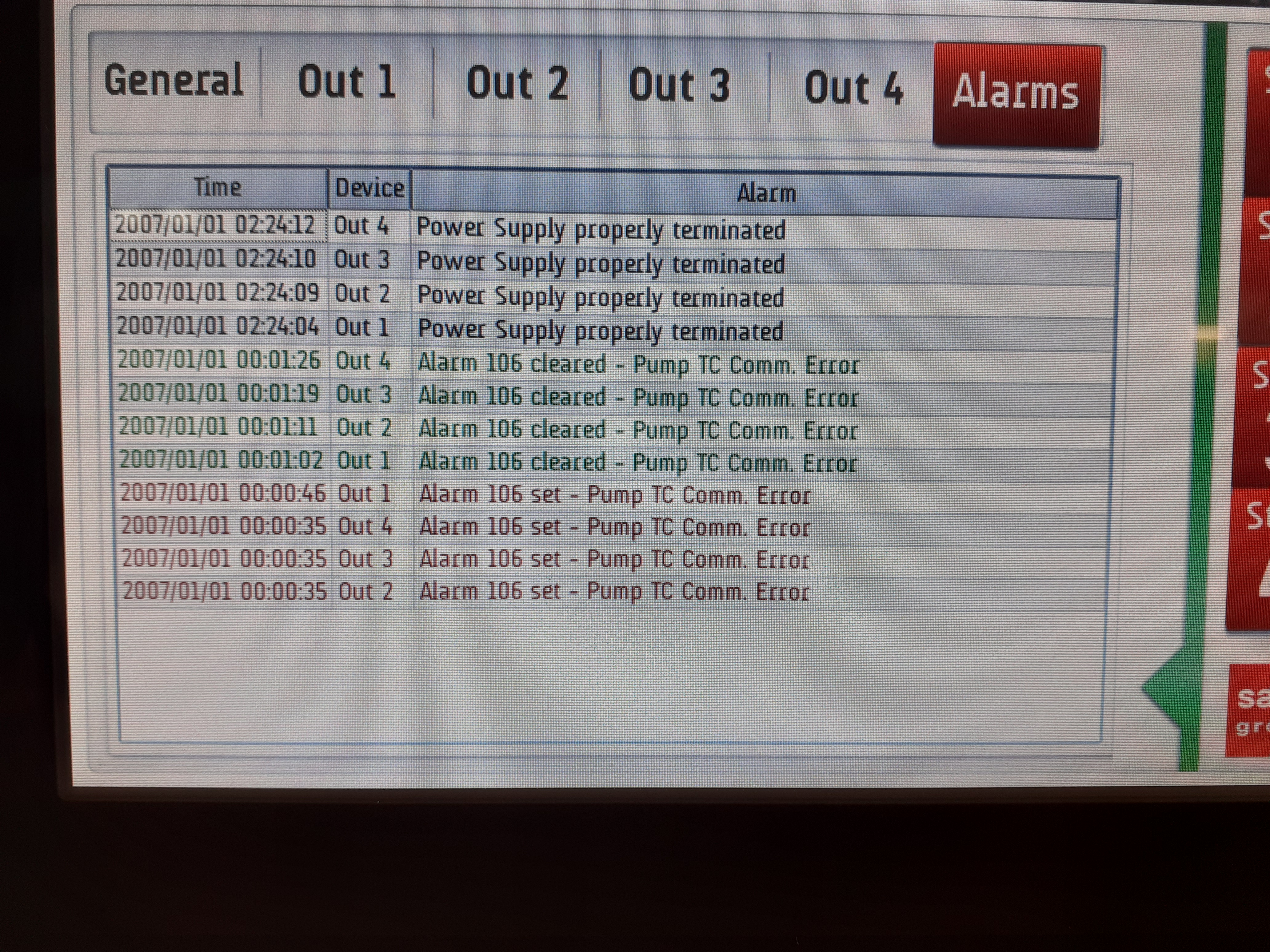
14.00

CARME chamber 2.78e-08mbar

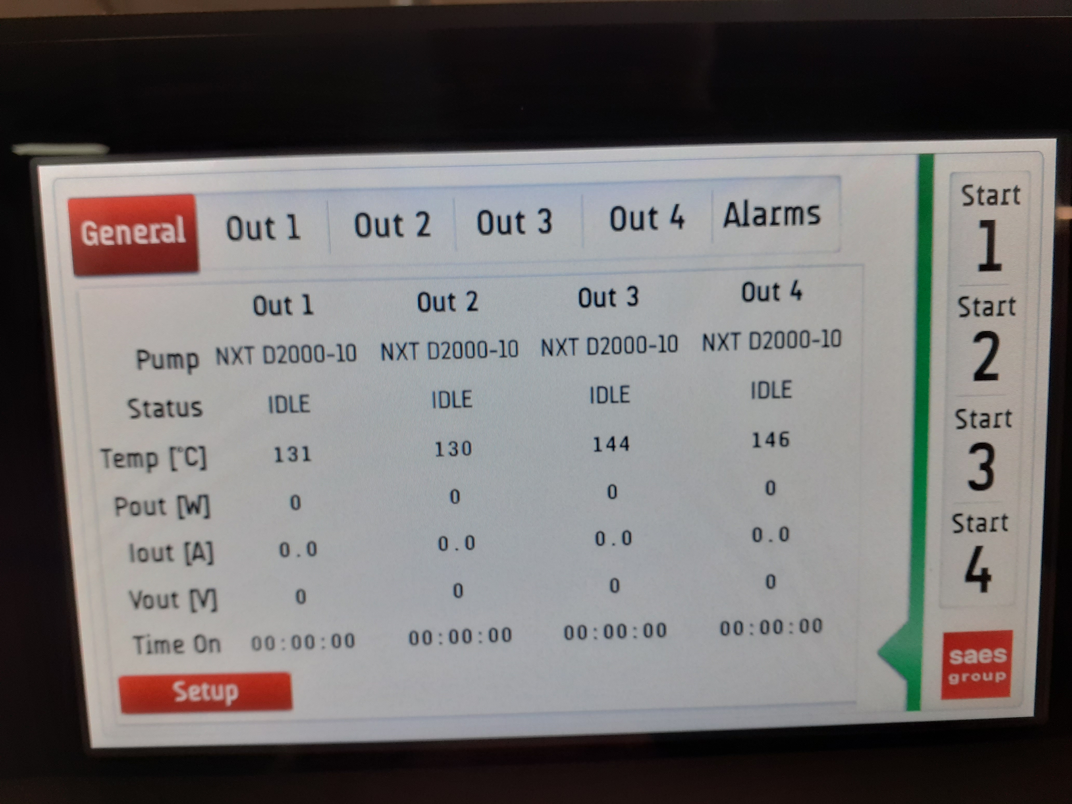
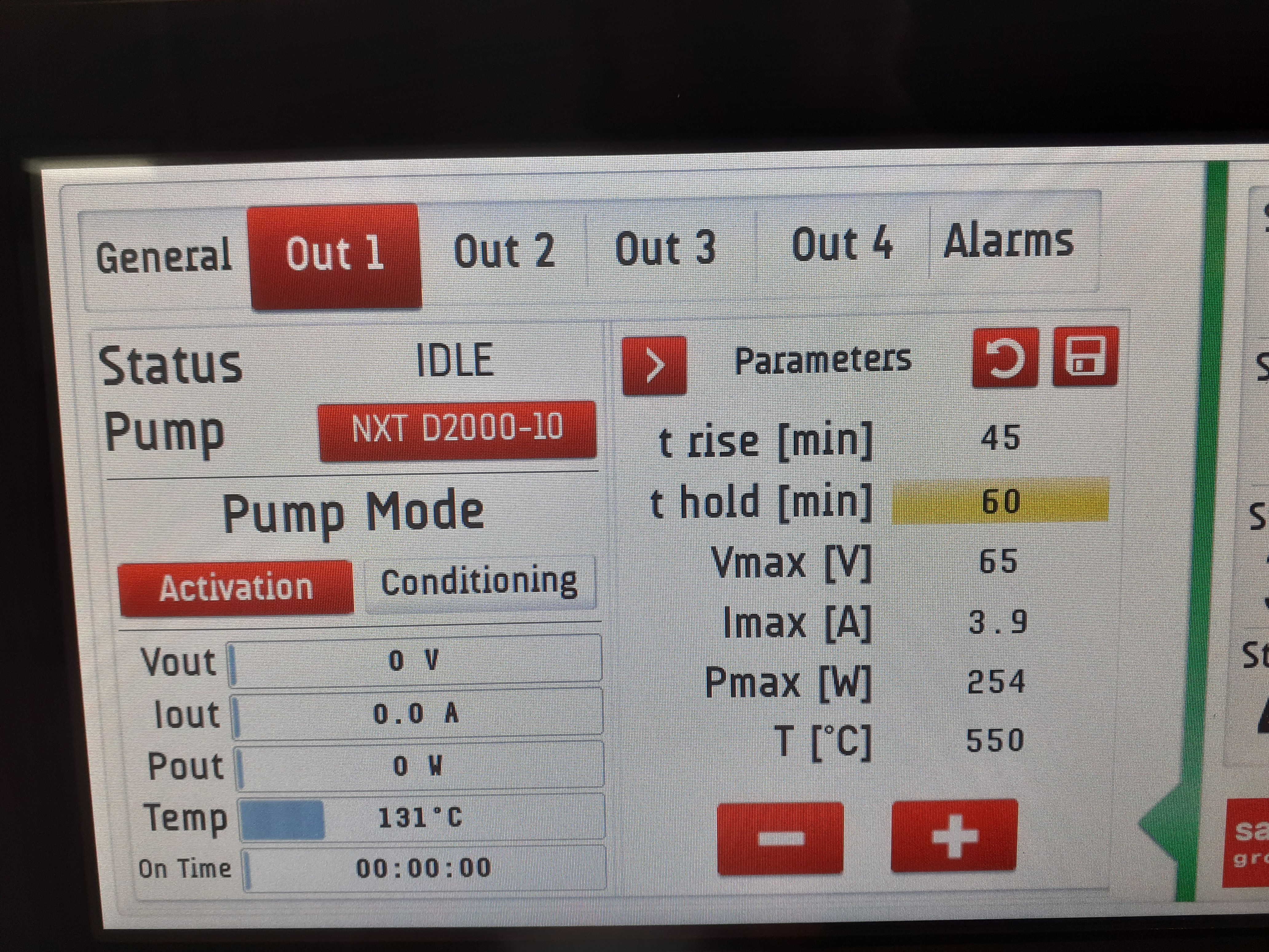
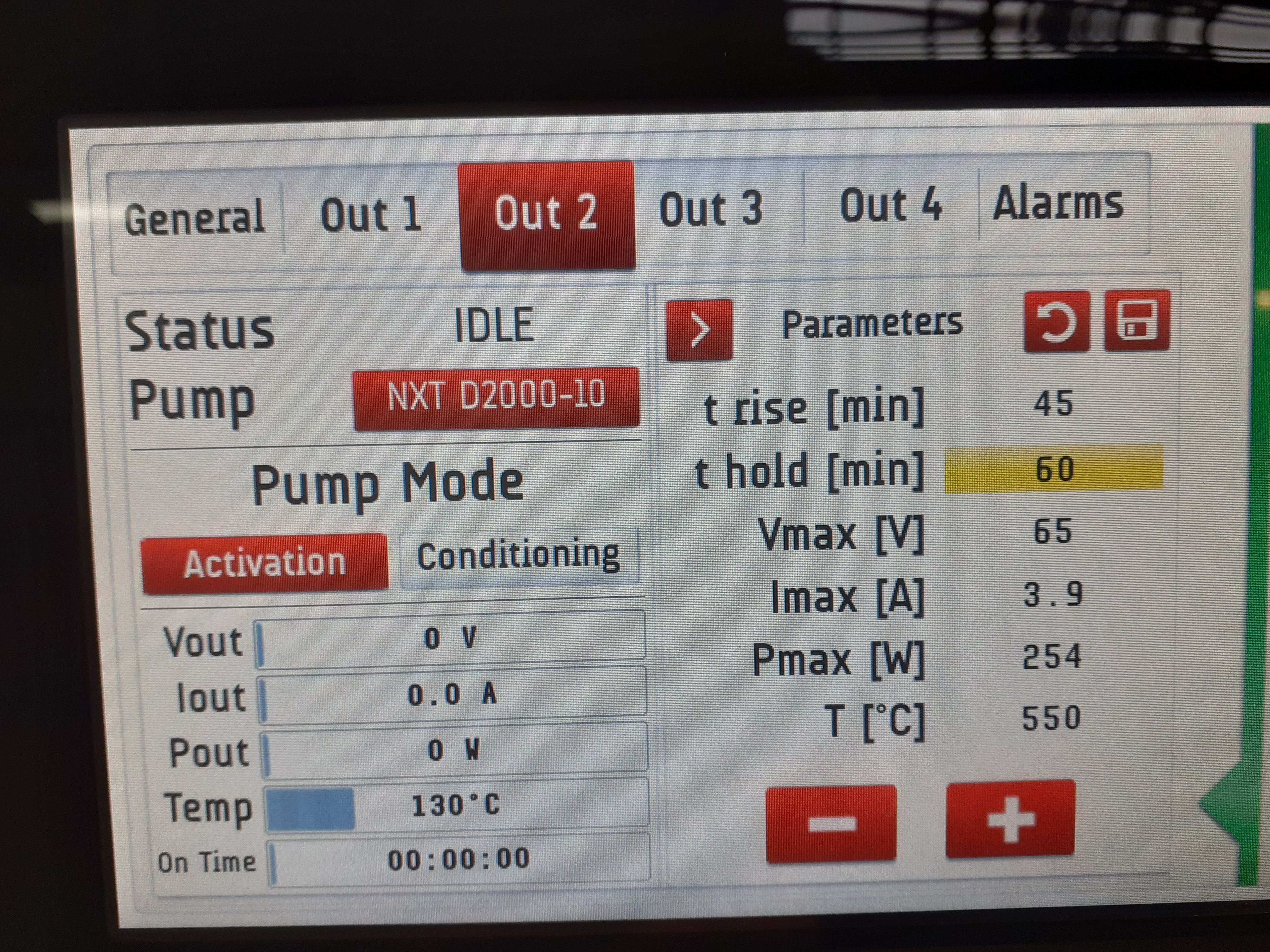
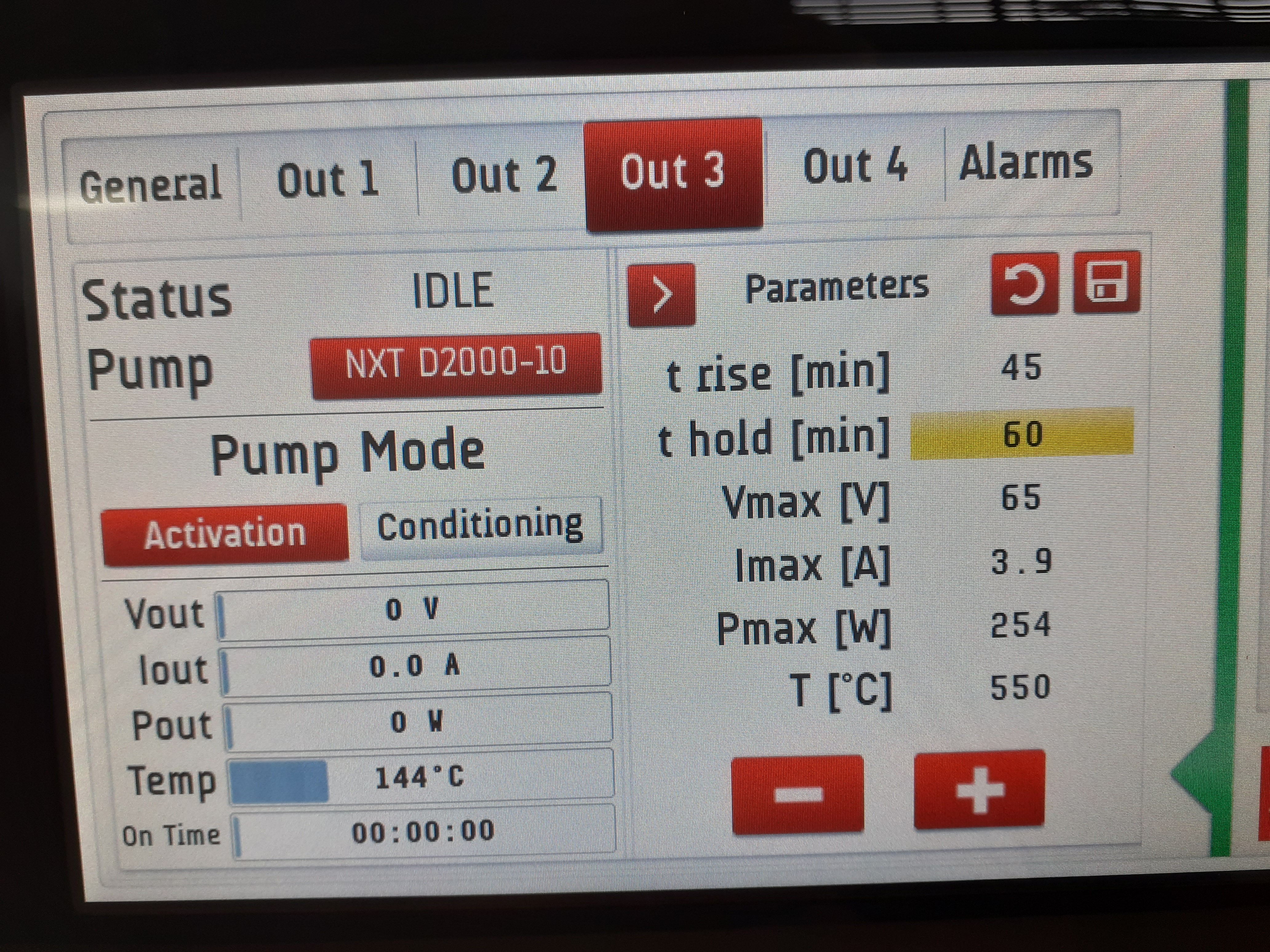
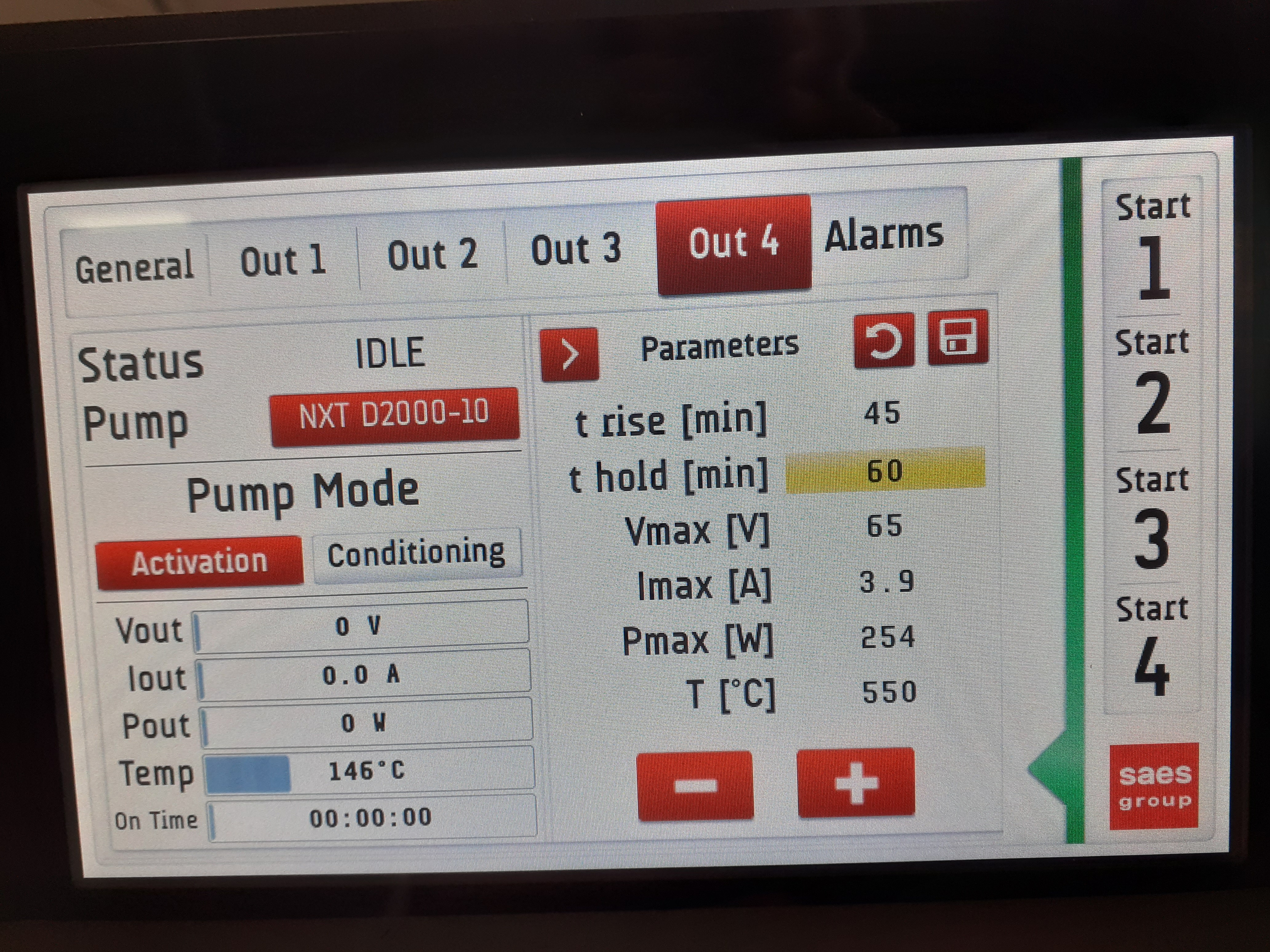
Start 4x SAES D2000-10 *NEG* pumps (ion pump OFF) - see attachments 13-18

Ramp 45 mins
Hold 60 mins
225W/550deg C

NEG pumps report temps c. 130 deg C

14.15 ramp

CARME chamber 2.0e-07mbar
Backing 3.3e-07mbar (Edwards vacuum cart w/RGA)
NEG pump temps c. 230-250 deg C

14.30 ramp

CARME chamber 2.34e-07mbar
Backing 4.1e-07mbar (Edwards vacuum cart w/RGA)
NEG pump temps c. 330-350 deg C

14.45 ramp

CARME chamber 4.02e-07mbar
Backing 4.1e-07mbar (Edwards vacuum cart w/RGA)
NEG pump temps c. 450-455 deg C

15.00 hold

CARME chamber 4.56e-07mbar
Backing 5.7e-07mbar (Edwards vacuum cart w/RGA)
NEG pump temps c. 500-505 deg C
output c. 50V, c. 3A, c. 150W

15.20 hold

CARME chamber 4.40e-07mbar
Backing 5.1e-07mbar (Edwards vacuum cart w/RGA)
NEG pump temps c. 530-540 deg C
output c. 160-170W

15.40 hold

CARME chamber 3.46e-07mbar
Backing 4.3e-07mbar (Edwards vacuum cart w/RGA)
NEG pump temps c. 540-545 deg C
output c. 160-170W

15.50 cycle complete

Ramp 45 mins
Hold inf mins
set output 60W

re-start CARME bakeout
set point +120 deg C

15.55 ramp

CARME chamber 5.15e-08mbar
Backing 1.4e-07mbar (Edwards vacuum cart w/RGA)
NEG pump temps c. 350-360 deg C

16.15 ramp

CARME chamber 4.53e-08mbar
Backing 1.5e-07mbar (Edwards vacuum cart w/RGA)
NEG pump temps c. 260-270 deg C

16.17 CARME chamber temperatures - attachment 20 |
| Attachment 1: 20201022_104309.jpg
|
|
| Attachment 2: 20201022_104331.jpg
|

|
| Attachment 3: 20201022_104339.jpg
|

|
| Attachment 4: 20201022_104345.jpg
|
|
| Attachment 5: 20201022_104354.jpg
|

|
| Attachment 6: 20201022_104354.jpg
|
|
| Attachment 7: 20201022_104412.jpg
|

|
| Attachment 8: 20201022_104415.jpg
|

|
| Attachment 9: 20201022_104419.jpg
|
|
| Attachment 10: 20201022_104427.jpg
|

|
| Attachment 11: 20201022_104431.jpg
|

|
| Attachment 12: 20201022_104434.jpg
|
|
| Attachment 13: 20201022_135913.jpg
|
|
| Attachment 14: 20201022_135921.jpg
|
|
| Attachment 15: 20201022_135926.jpg
|
|
| Attachment 16: 20201022_135930.jpg
|
|
| Attachment 17: 20201022_135935.jpg
|
|
| Attachment 18: 20201022_135942.jpg
|

|
| Attachment 19: 20201022_161737.jpg
|
|
|
475
|
Thu Jan 18 17:21:00 2024 |
TD | Thursday 18 January |
Network ( dhcpd.conf ) and MIDAS startup.tcl/Options/ASIC settings/rfs filesystems configured


17.20 CARME IE514 4.1e-11mbar, ambient temperature 16.7 deg C
Pressure appears to be drifting upwards - see attachment 1 |
| Attachment 1: Capture.PNG
|

|
|
541
|
Thu Apr 18 13:34:06 2024 |
TD, JG | Thursday 18 April |
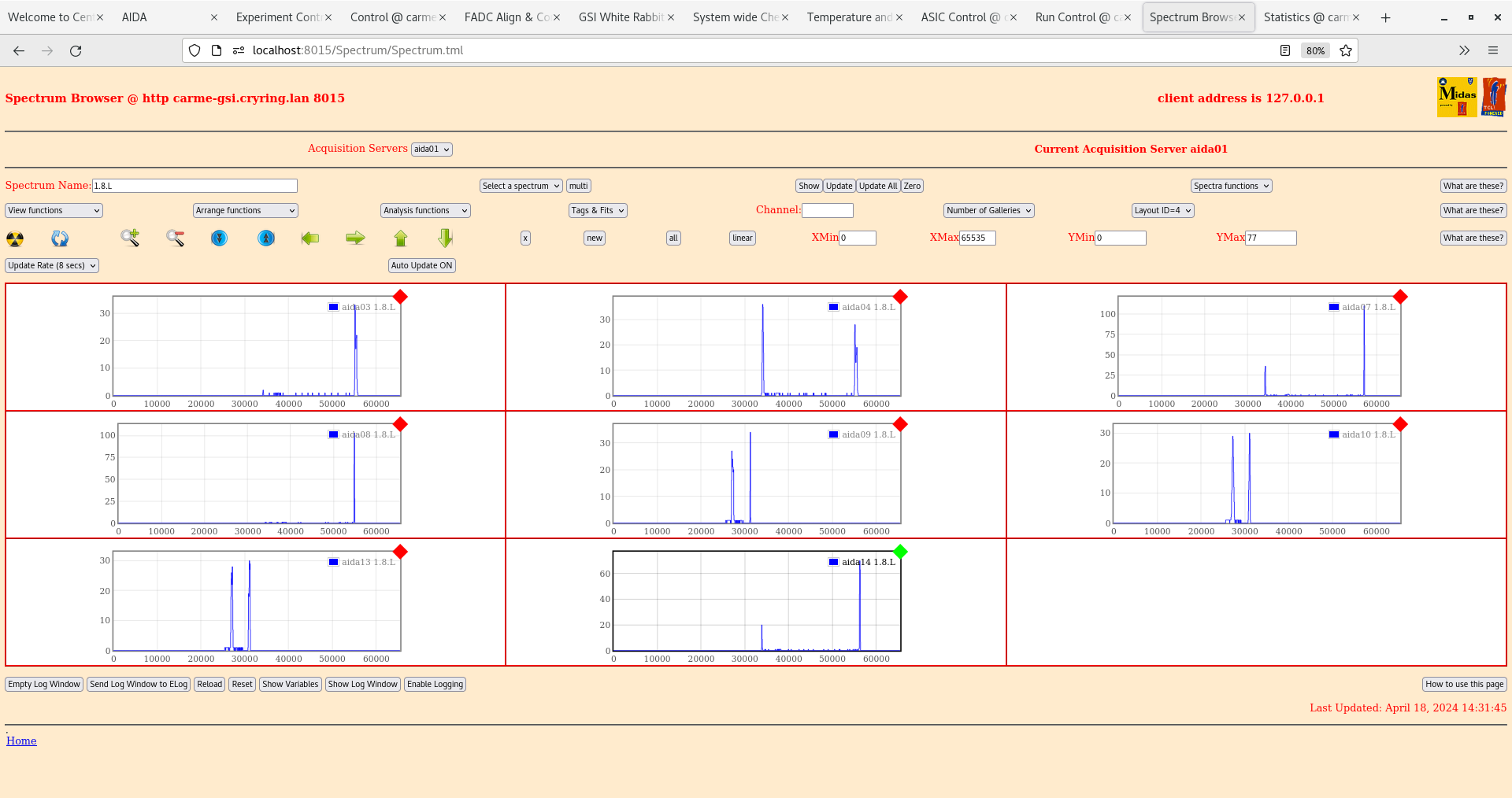
14.30


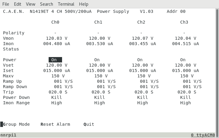
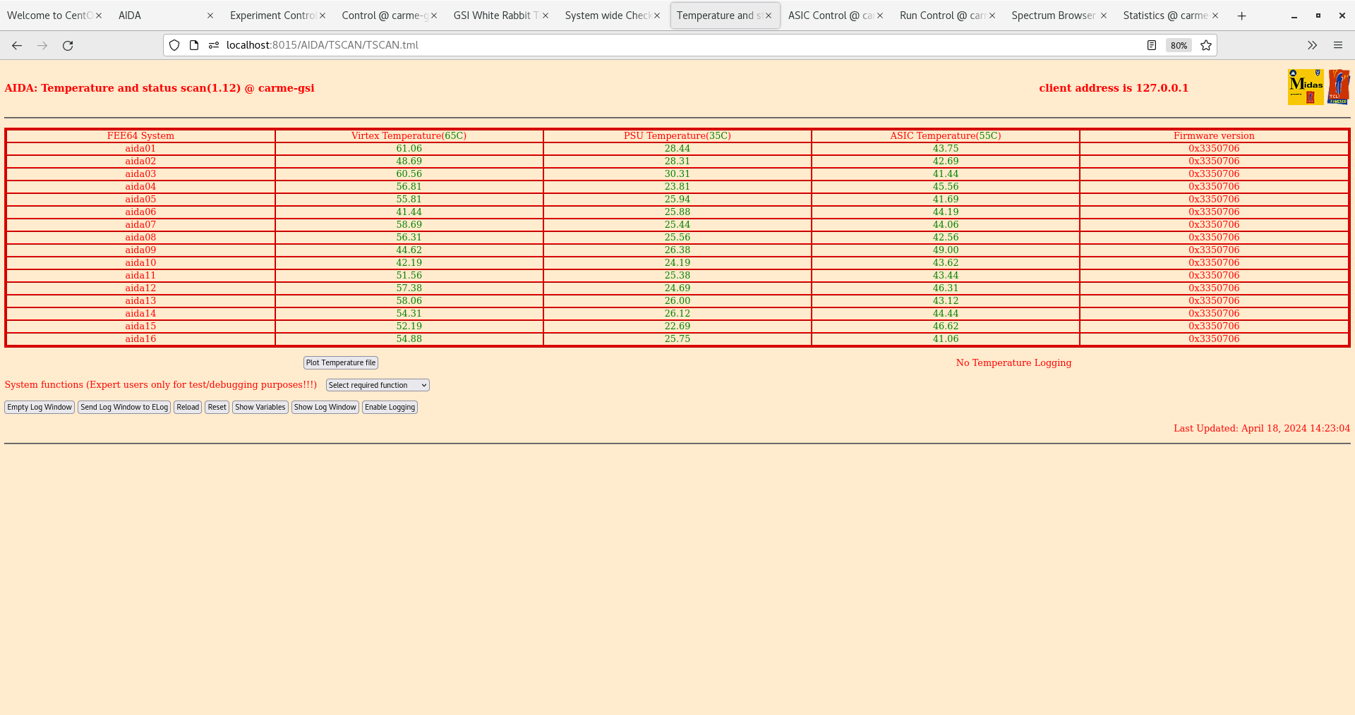
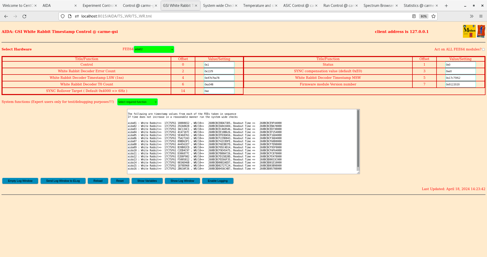
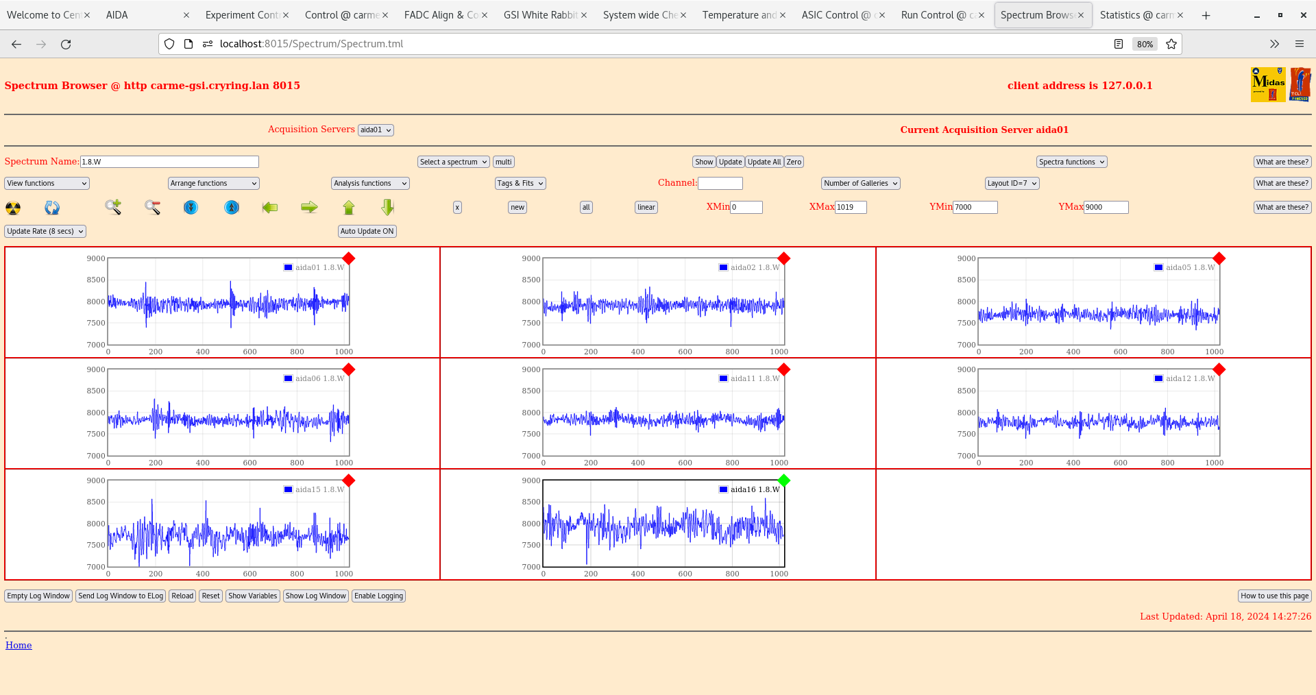
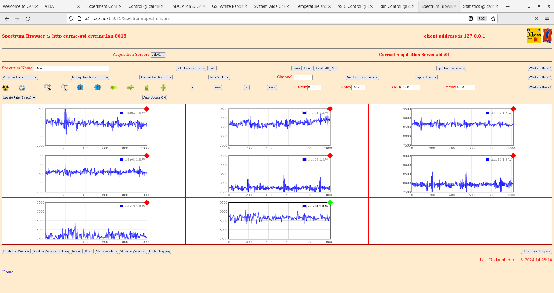
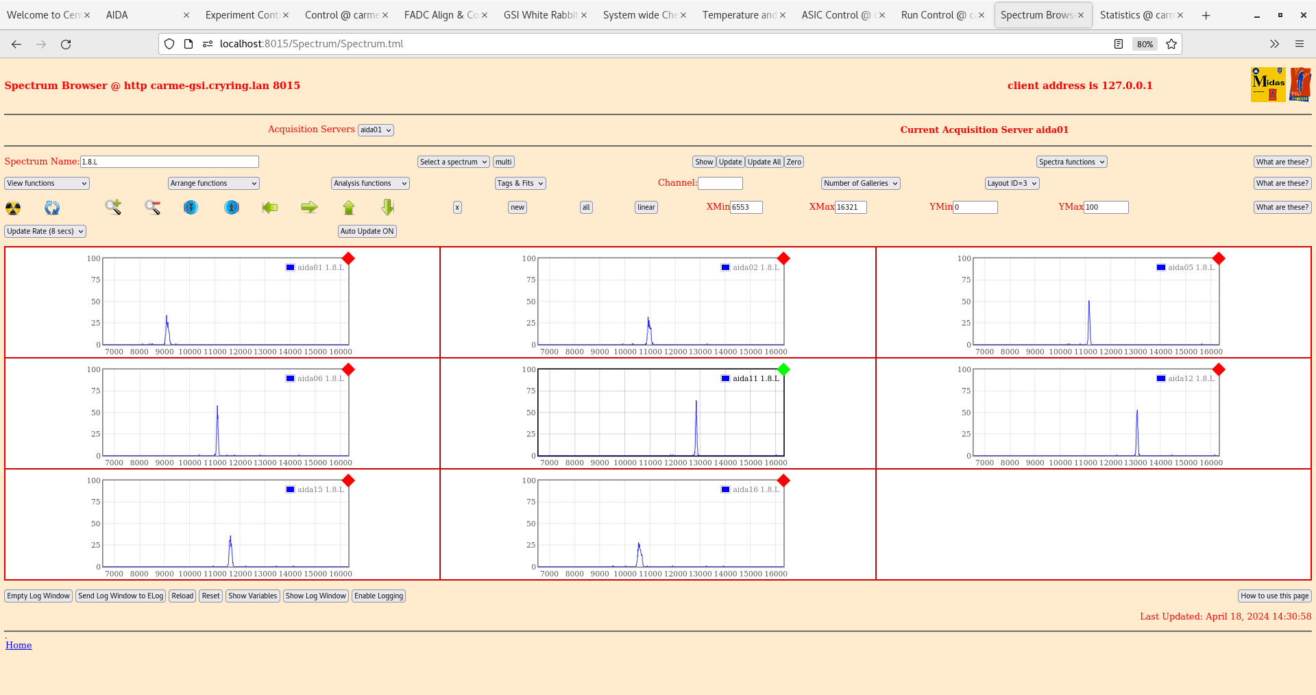
       per FEE64 1.8.L spectra
        aida11 pulser peak width 52 ch FWHM


14.45 EG&G Ortec 448 Pulser OFF

      all stats & histograms zero'd

      alpha background


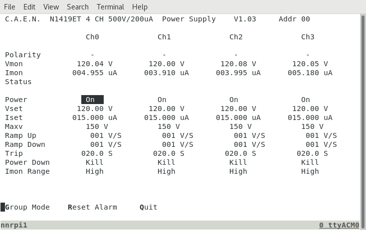
22.00 DSSSD bias and leakage current OK - attachment 10

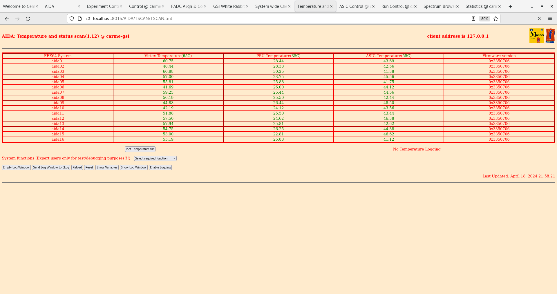
      FEE64 temperatures OK - attachment 11

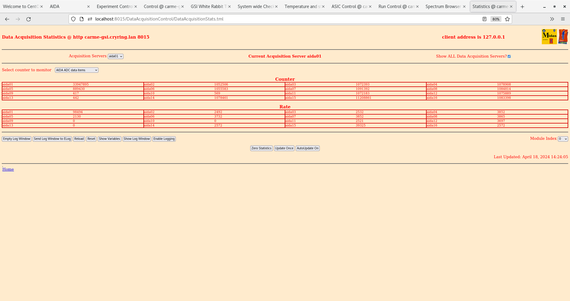
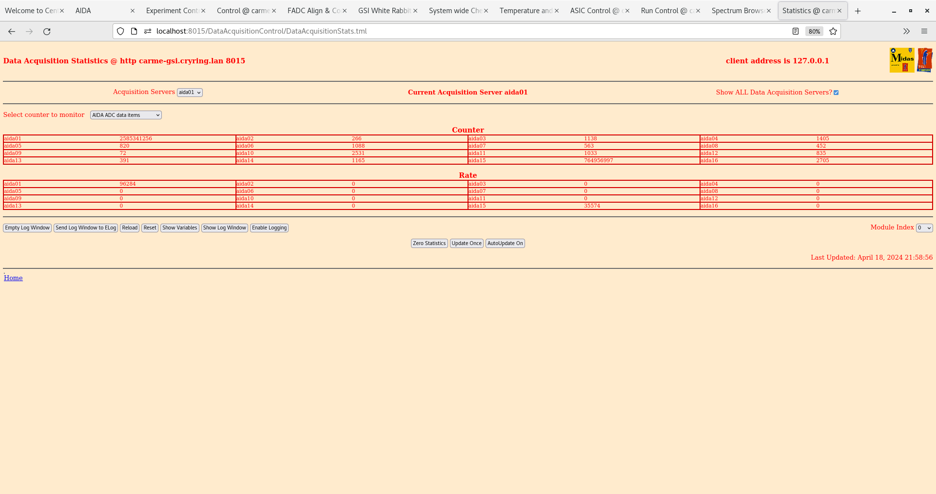
      ADC data item stats - attachment 12

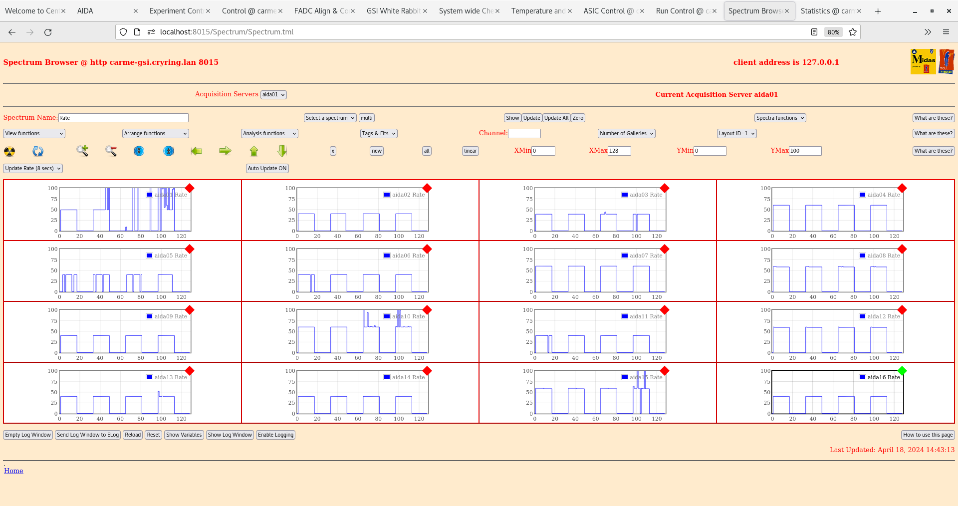
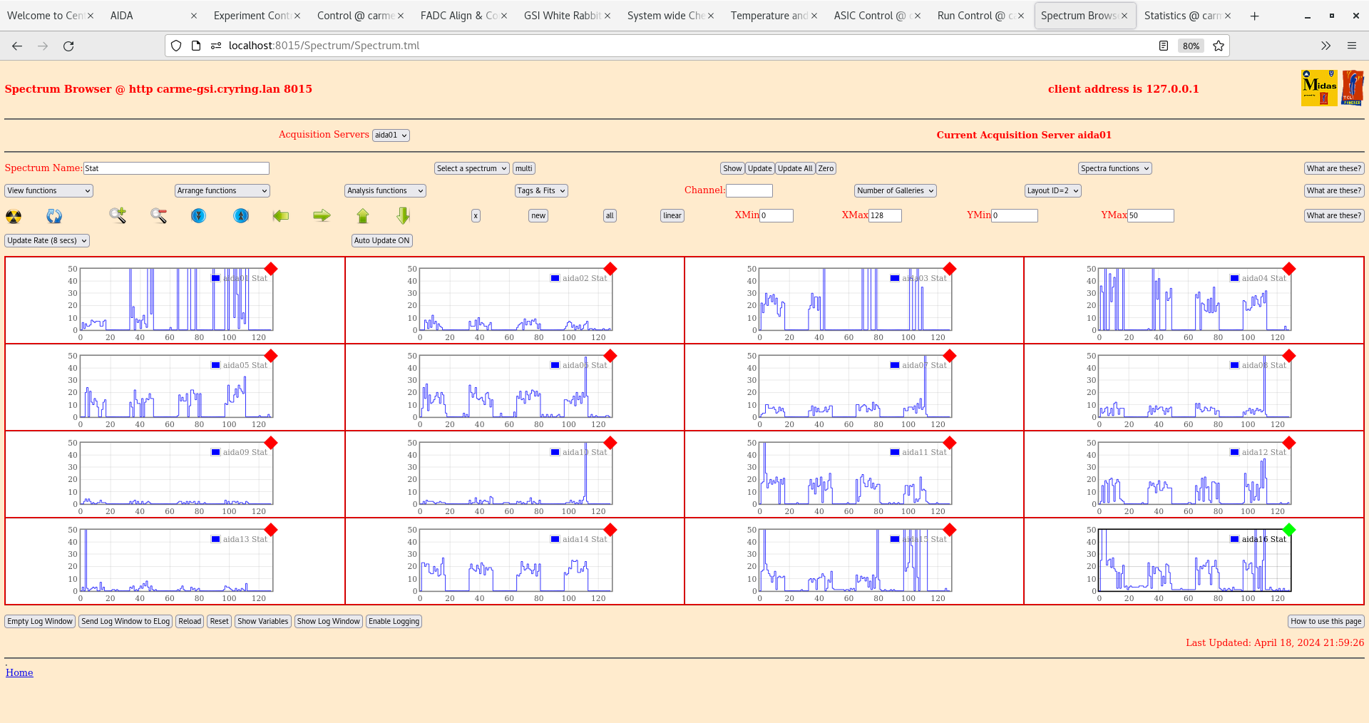
      per FEE64 Stat spectra - attachment 13
       Comparison of attachment 9 (per FEE64 Rate spectra with pulser) indicates significant issues (downstream of adaptor PCB) for DSSSD #1
Possible issues asics #3 aida01 and possible adaptor PCB misalignment aida05 |
| Attachment 1: Screenshot_from_2024-04-18_14-22-41.png
|
|
| Attachment 2: Screenshot_from_2024-04-18_14-23-10.png
|
|
| Attachment 3: Screenshot_from_2024-04-18_14-23-51.png
|
|
| Attachment 4: Screenshot_from_2024-04-18_14-24-18.png
|
|
| Attachment 5: Screenshot_from_2024-04-18_14-27-33.png
|
|
| Attachment 6: Screenshot_from_2024-04-18_14-28-26.png
|
|
| Attachment 7: Screenshot_from_2024-04-18_14-31-14.png
|
|
| Attachment 8: Screenshot_from_2024-04-18_14-32-31.png
|
|
| Attachment 9: Screenshot_from_2024-04-18_14-43-27.png
|
|
| Attachment 10: Screenshot_from_2024-04-18_21-57-51.png
|
|
| Attachment 11: Screenshot_from_2024-04-18_21-58-31.png
|
|
| Attachment 12: Screenshot_from_2024-04-18_21-59-11.png
|
|
| Attachment 13: Screenshot_from_2024-04-18_21-59-35.png
|
|
|
123
|
Thu Oct 14 15:54:47 2021 |
TD RSS | Thursday 14 October |
Attachment 1 - what is function of the 4x c/s holes indicated?


DSSSD install sequence

1 add 136 - 2x78 way cable harnesses to DSSSD mount via strain relief

2 add DSSSD to mount

3 connect 136 D connector

4 install in CARME chamber

5 connect 2x78 D connectors and strain relief to 2x78 way D connector
feedthroughs

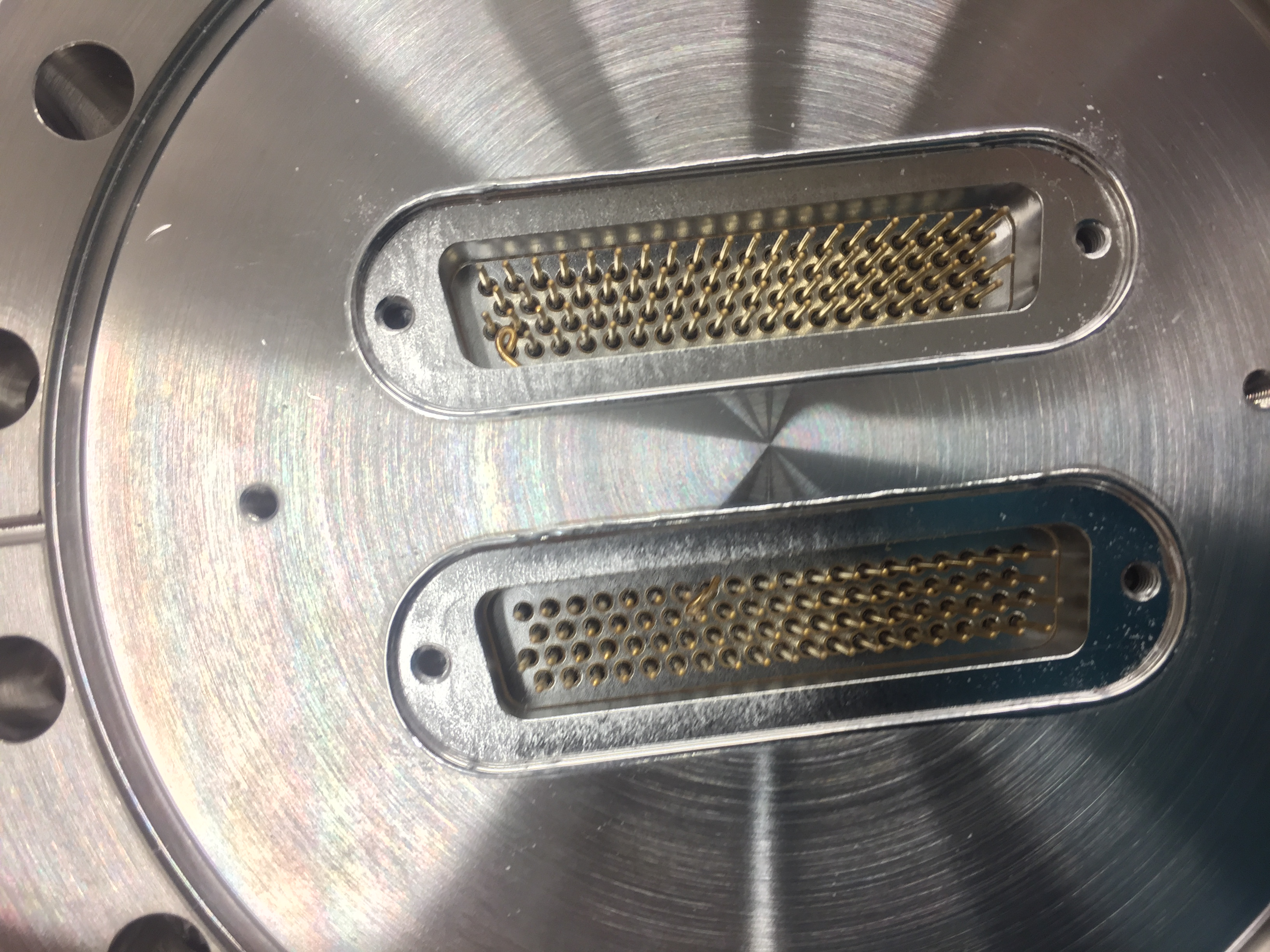
Attachment 2- pins of one of the four feedthroughs were damaged. Needs to be replaced. |
| Attachment 1: IMG_5056.JPG.jpg
|

|
| Attachment 2: IMG_5053.JPG
|
|
|
41
|
Thu Aug 12 09:16:42 2021 |
TD RSS | Thursday 12 August |
Attachment 1 - IE414/514 feedthrough wiring diagram

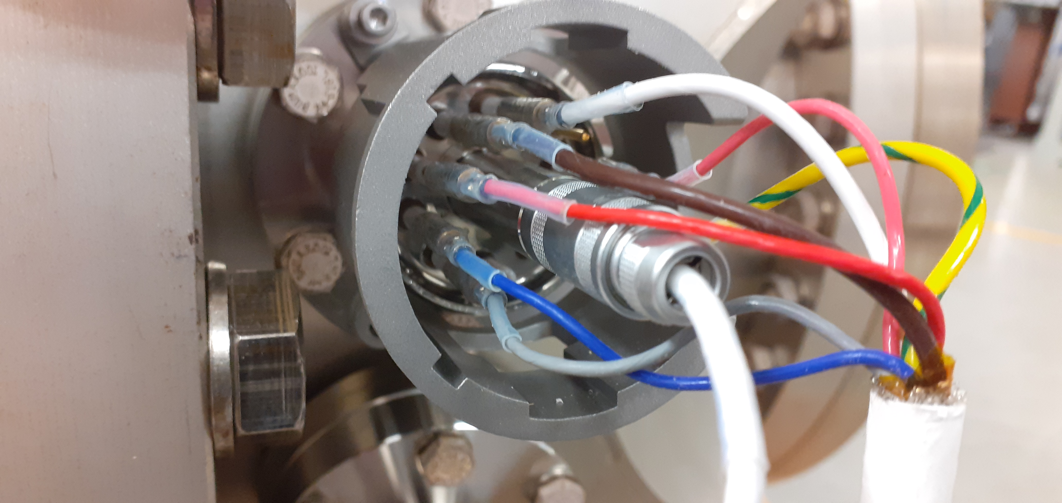
Attachments 2 & 3 - IE514 feedthrough connected (cf https://elog.ph.ed.ac.uk/CARME/19 )

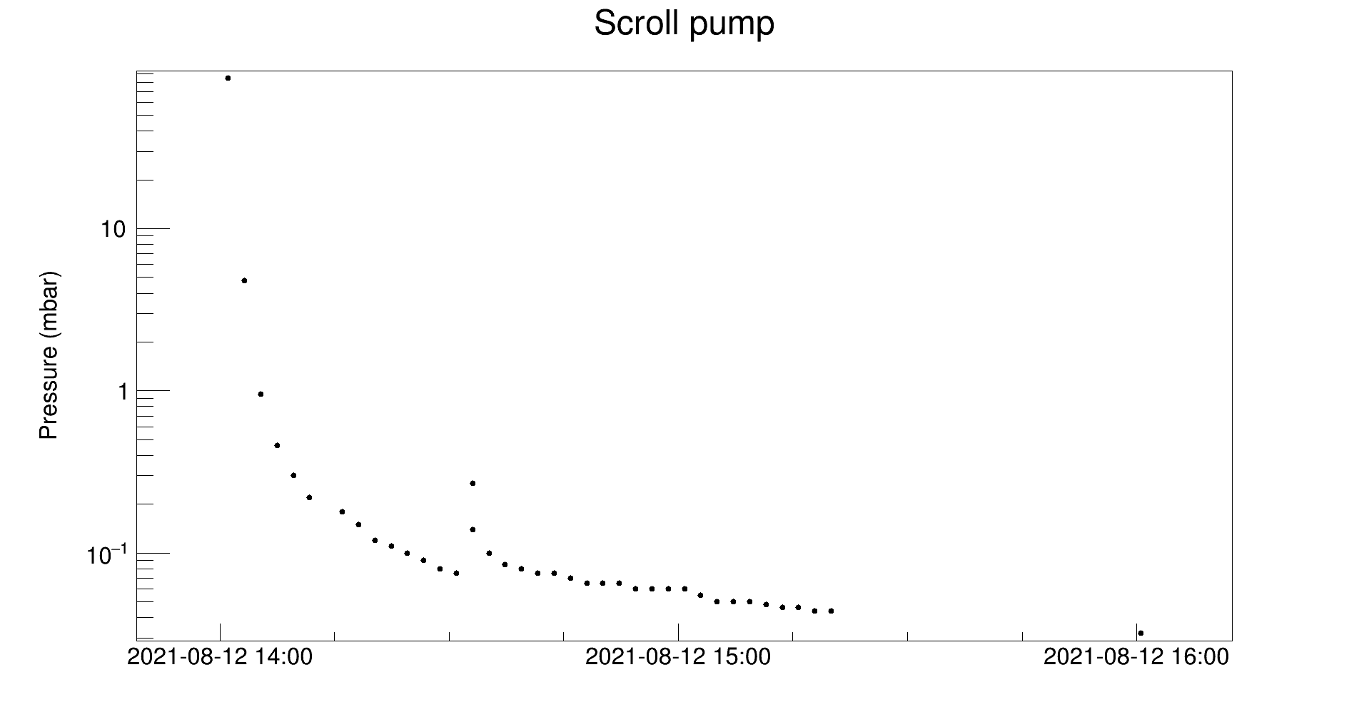
14:00 scroll pump start
14:30 turbo pump start
15:16 1.00e-5mbar
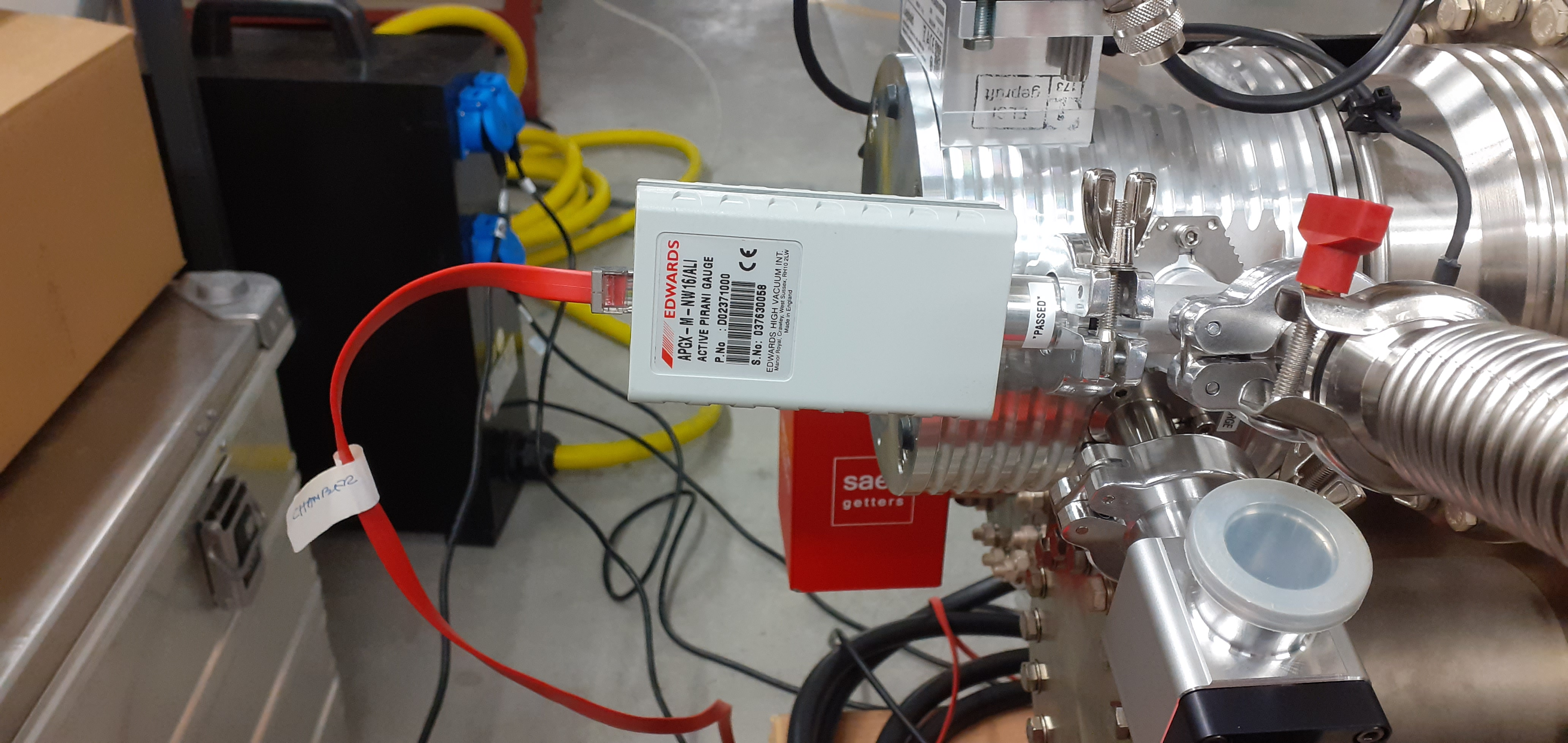
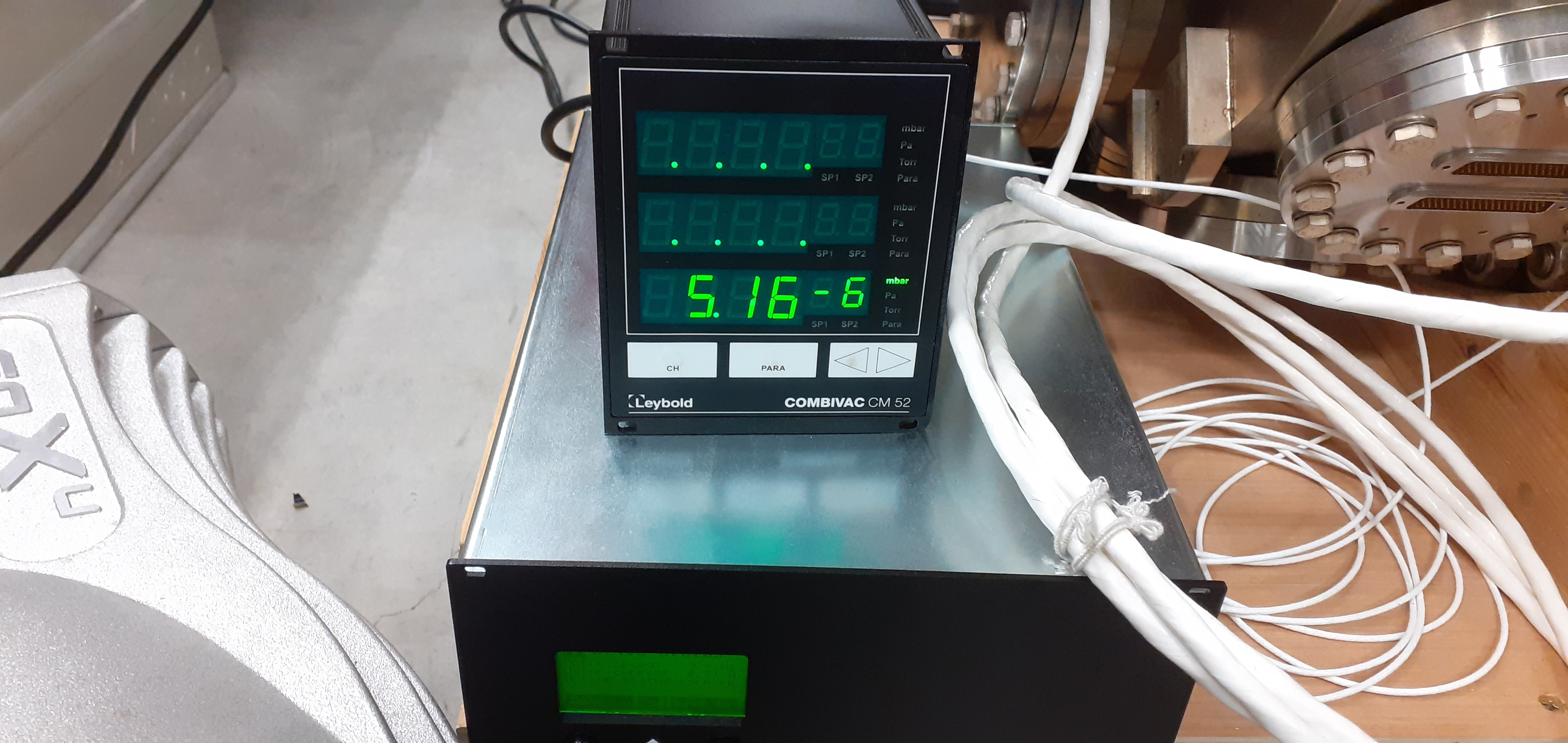
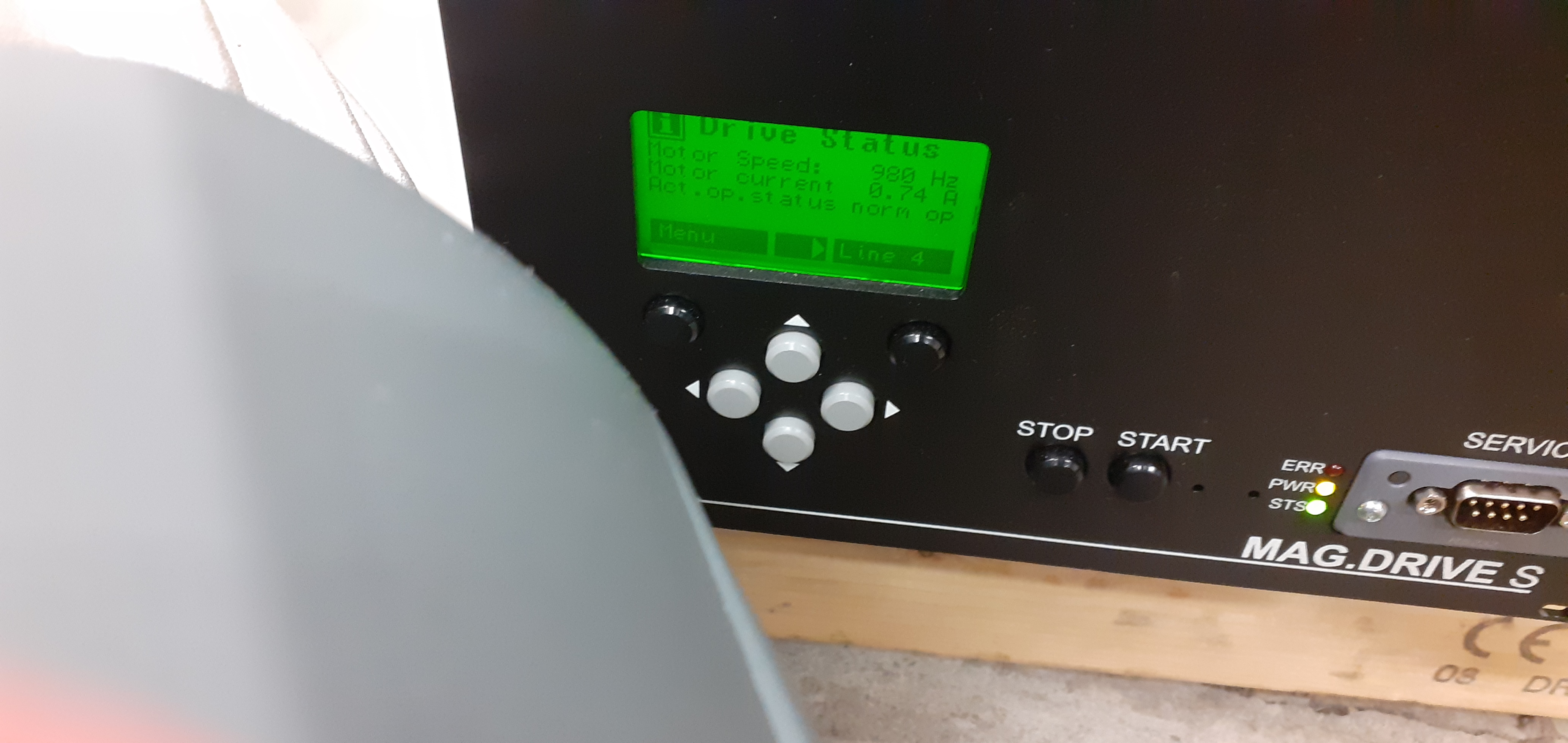
16:01 - attachments 4-8 basic vacuum test setup
        turbo @ 0.74A

              Pirani  IE514
              mbar    mbar

12/8/21 14:02 85
12/8/21 14:04 4.8
12/8/21 14:06 0.95
12/8/21 14:08 0.46
12/8/21 14:10 0.30
12/8/21 14:12 0.22
12/8/21 14:16 0.18
12/8/21 14:18 0.15
12/8/21 14:20 0.12
12/8/21 14:22 0.11
12/8/21 14:24 0.10
12/8/21 14:26 0.090
12/8/21 14:28 0.080
12/8/21 14:30 0.075
12/8/21 14:32 0.27
12/8/21 14:34 0.14
12/8/21 14:36 0.10
12/8/21 14:37:20    7.00e-5
12/8/21 14:38 0.085 5.80e-5
12/8/21 14:40 0.080 4.61e-5
12/8/21 14:42 0.075 3.73e-5
12/8/21 14:44 0.075 3.14e-5
12/8/21 14:46 0.070 2.70e-5
12/8/21 14:48 0.065 2.42e-5
12/8/21 14:50 0.065 2.16e-5
12/8/21 14:52 0.065 1.97e-5
12/8/21 14:54 0.060 1.81e-5
12/8/21 14:56 0.060 1.70e-5
12/8/21 14:58 0.060 1.57e-5
12/8/21 15:00 0.060 1.47e-5
12/8/21 15:02 0.055 1.39e-5
12/8/21 15:04 0.055 1.31e-5
12/8/21 15:06 0.050 1.26e-5
12/8/21 15:08 0.050 1.20e-5
12/8/21 15:10 0.050 1.14e-5
12/8/21 15:12 0.048 1.09e-5
12/8/21 15:14 0.046 1.04e-5
12/8/21 15:16 0.046 1.00e-5
12/8/21 15:18 0.044 9.65e-6
12/8/21 15:20 0.044 9.31e-6
12/8/21 16:00 0.032 5.28e-6

--------------------------------

13/8/21 08:00 0.0075 3.53e-7 |
| Attachment 1: 20210812_101505.jpg
|

|
| Attachment 2: 20210812_101537.jpg
|

|
| Attachment 3: 20210812_101545.jpg
|
|
| Attachment 4: 20210812_160134.jpg
|

|
| Attachment 5: 20210812_160158.jpg
|
|
| Attachment 6: 20210812_160210.jpg
|
|
| Attachment 7: 20210812_160215.jpg
|
|
| Attachment 8: 20210812_160222.jpg
|

|
| Attachment 9: IMG_4196.JPG
|

|
| Attachment 10: IMG_4197.JPG
|

|
| Attachment 11: IMG_4198.JPG
|

|
| Attachment 12: scroll_pump.png
|
|
| Attachment 13: turbo_pump.png
|

|
|
8
|
Thu Sep 10 11:34:30 2020 |
TD, JM | Thursday 10 September |
All neg feed-throughs have now been fully installed, with ground tags
and power wires crimped and attached to the correct pins. Feed-throughs
are installed as seen in Image
1 of zip file, with mark at the top of the feed-through. The pin
assignment is seen in Image 2. The pins are assigned letters A to F,
with F the top pin and C the bottom
pin as installed(refer to images 1+2). The ground is pin c, with the
two power wires connected to the bottom pins either side of the ground
(pins b and d). Connections of
wires from the negs to the feed-through is seen in image 3. Feed-
throughs have been electrically checked. The ground pin is checked
against the chamber giving
approx 0.5 ohms and the power pins are checked together giving 5-10
ohms. Each of the power pins are open circuit with respect to the
ground. A
thermocouple has been attached under the bolt of one of the neg pumps
(image 4).

Pirani gauge and hot cathode gauge have been installed on the chamber
(images 5,6,7,8) on the section furthest from the turbos.

Upper valve, turbo and supports have all now been installed (images
9,10,11). Images 12,13 are of the internal of the turbo and turbo
ports. The lower valve supports
produced by the Daresbury group (image 14) are also now attached. These
supports were required as the lower valve sits higher than anticipated
due to shorter right-angled
flanges.

Chamber is now ready to close and leak test! |
| Attachment 1: 20200910_112152.jpg
|
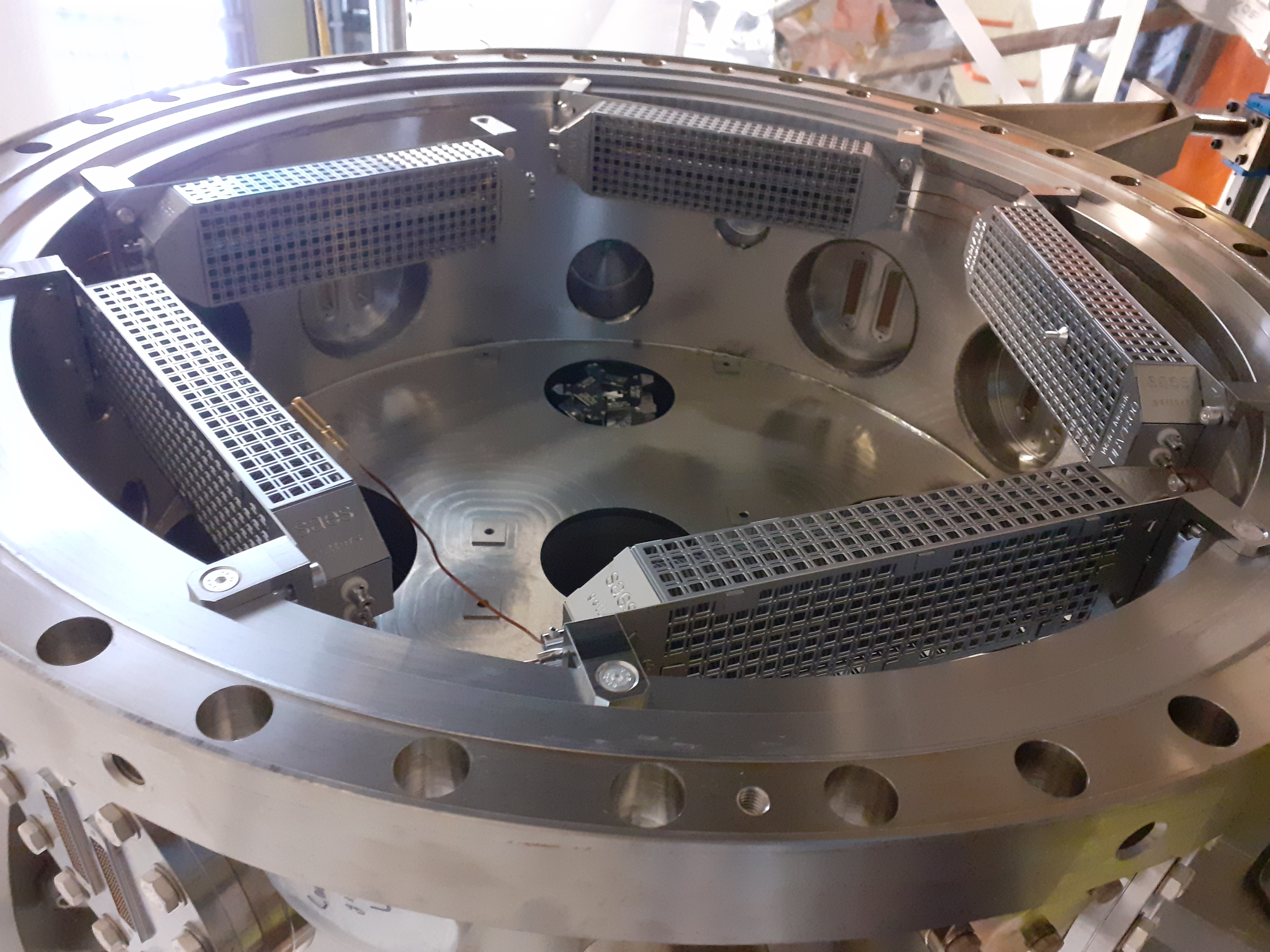
|
| Attachment 2: 20200910_112211.jpg
|

|
| Attachment 3: Photos_(1).zip
|
|
672
|
Thu Apr 10 10:53:14 2025 |
TD | Thursday 10 April |
11.50 DAQ continues
      Data file APR25/R6_13

      DSSSD bias & leakage current - attachment 1

      FEE64 temps OK - attachment 2

      ADC data item stats - attachment 3

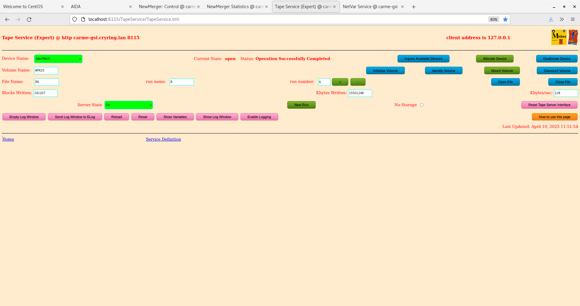
      Merger & Tape Server - attachment 4-5

      Disk file log - attachment 6
       event rate increased significantly at some point this morning but is currently OK


19.21 FEE64 power OFF - aida08 high temperature

      DSSSD bias & leakage current - attachment 7

      FEE64 temps - attachment 8
aida08 high temperature - FEE64 power OFF, detector HV OFF |
| Attachment 1: Screenshot_from_2025-04-10_11-50-32.png
|

|
| Attachment 2: Screenshot_from_2025-04-10_11-51-02.png
|

|
| Attachment 3: Screenshot_from_2025-04-10_11-51-35.png
|

|
| Attachment 4: Screenshot_from_2025-04-10_11-51-48.png
|

|
| Attachment 5: Screenshot_from_2025-04-10_11-52-02.png
|
|
| Attachment 6: Screenshot_from_2025-04-10_11-53-45.png
|

|
| Attachment 7: Screenshot_from_2025-04-10_19-20-23.png
|

|
| Attachment 8: Screenshot_from_2025-04-10_19-20-51.png
|

|
|
383
|
Thu Dec 1 08:56:59 2022 |
AR TD | Thursday 1 December |
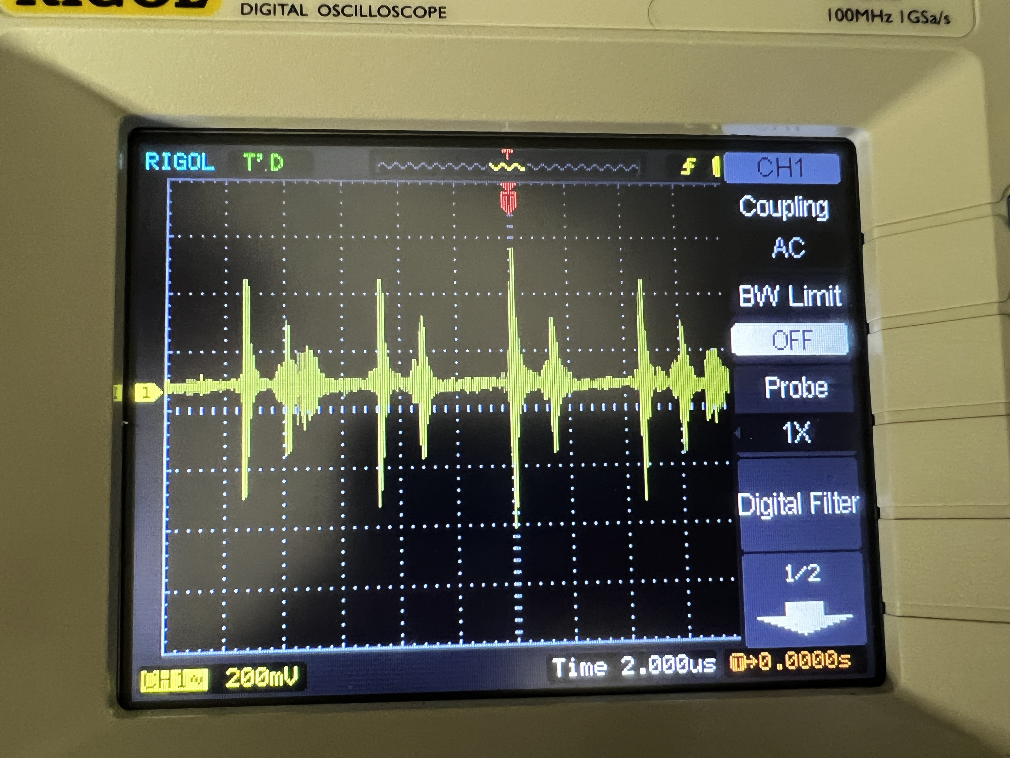
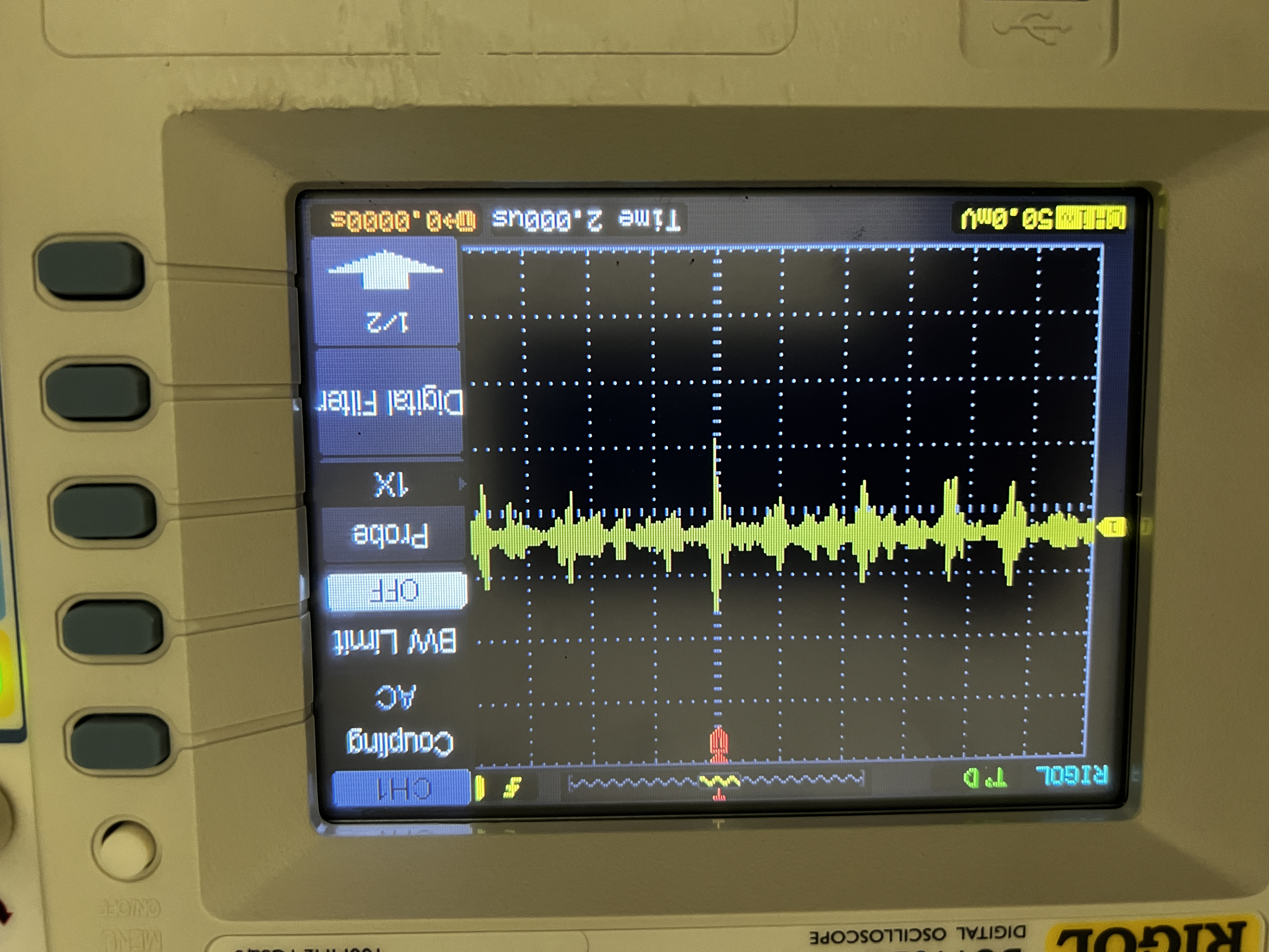
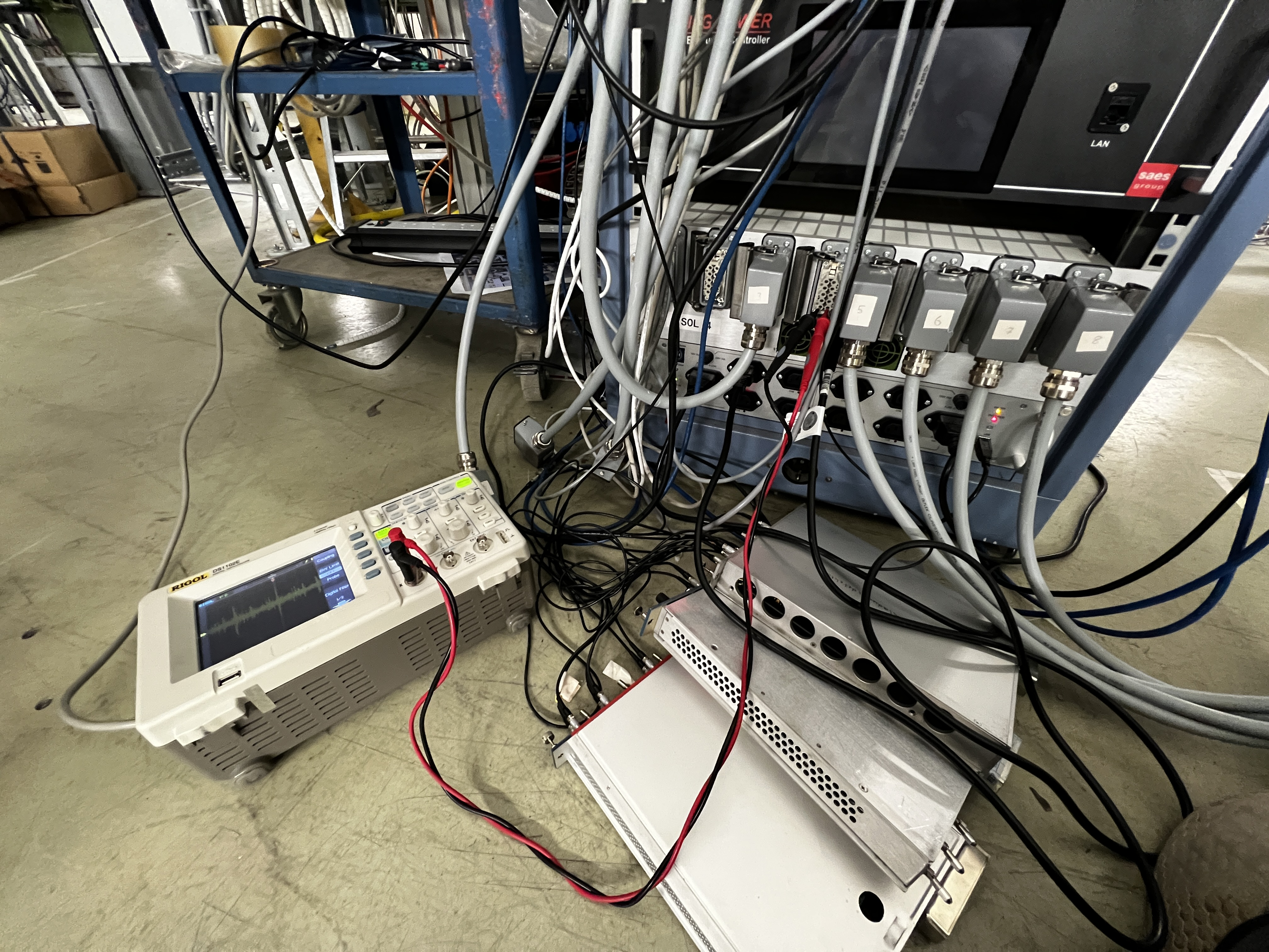
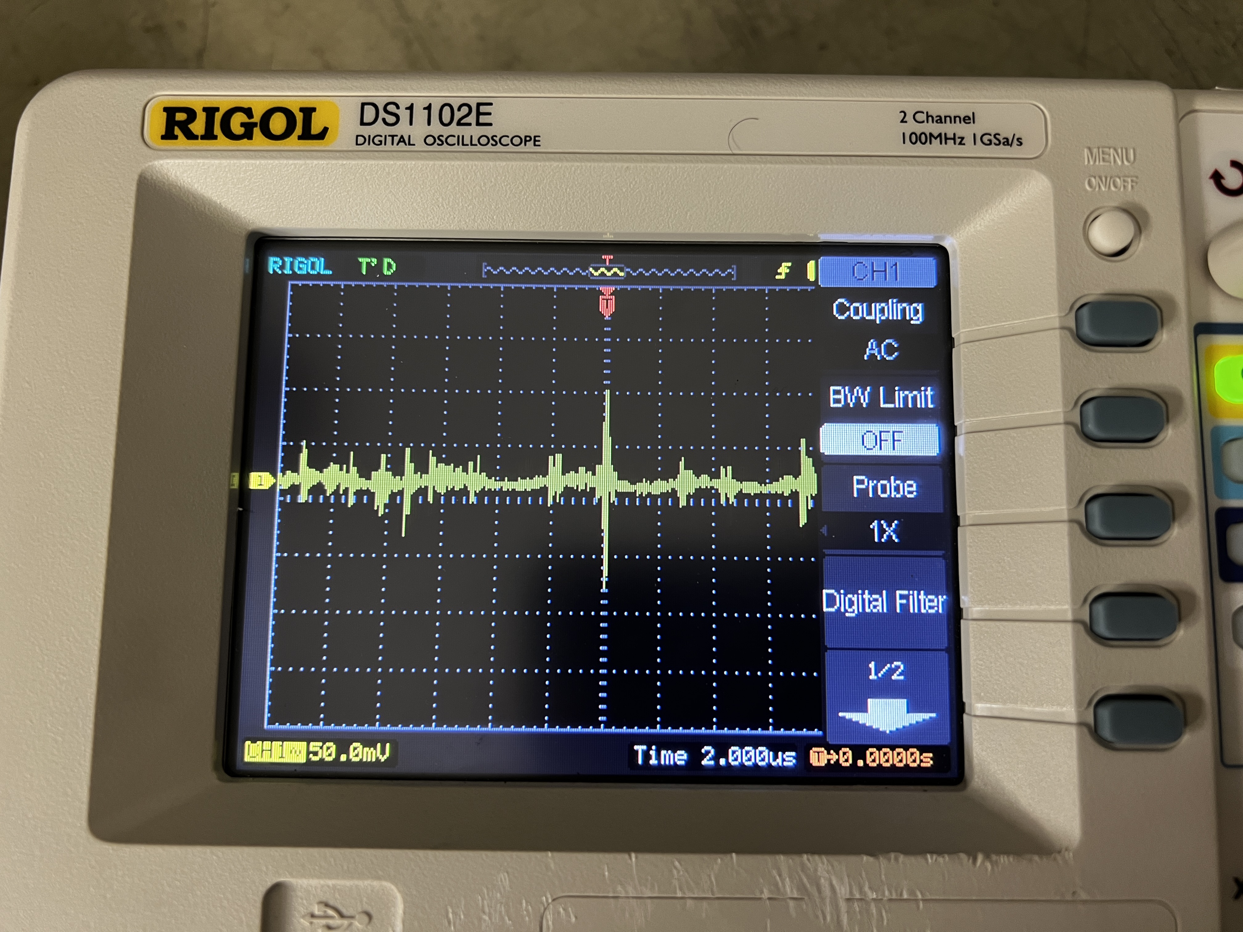
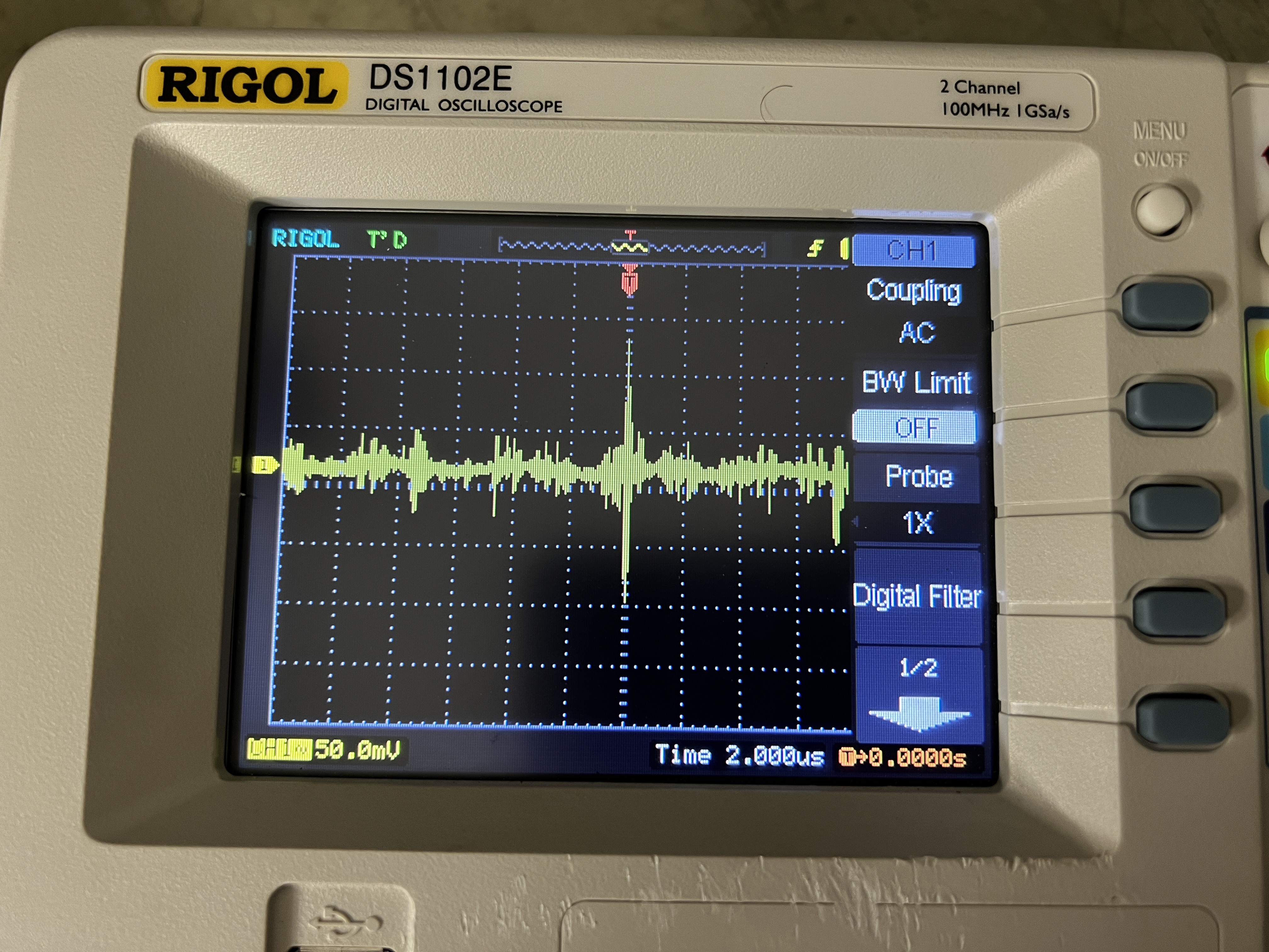
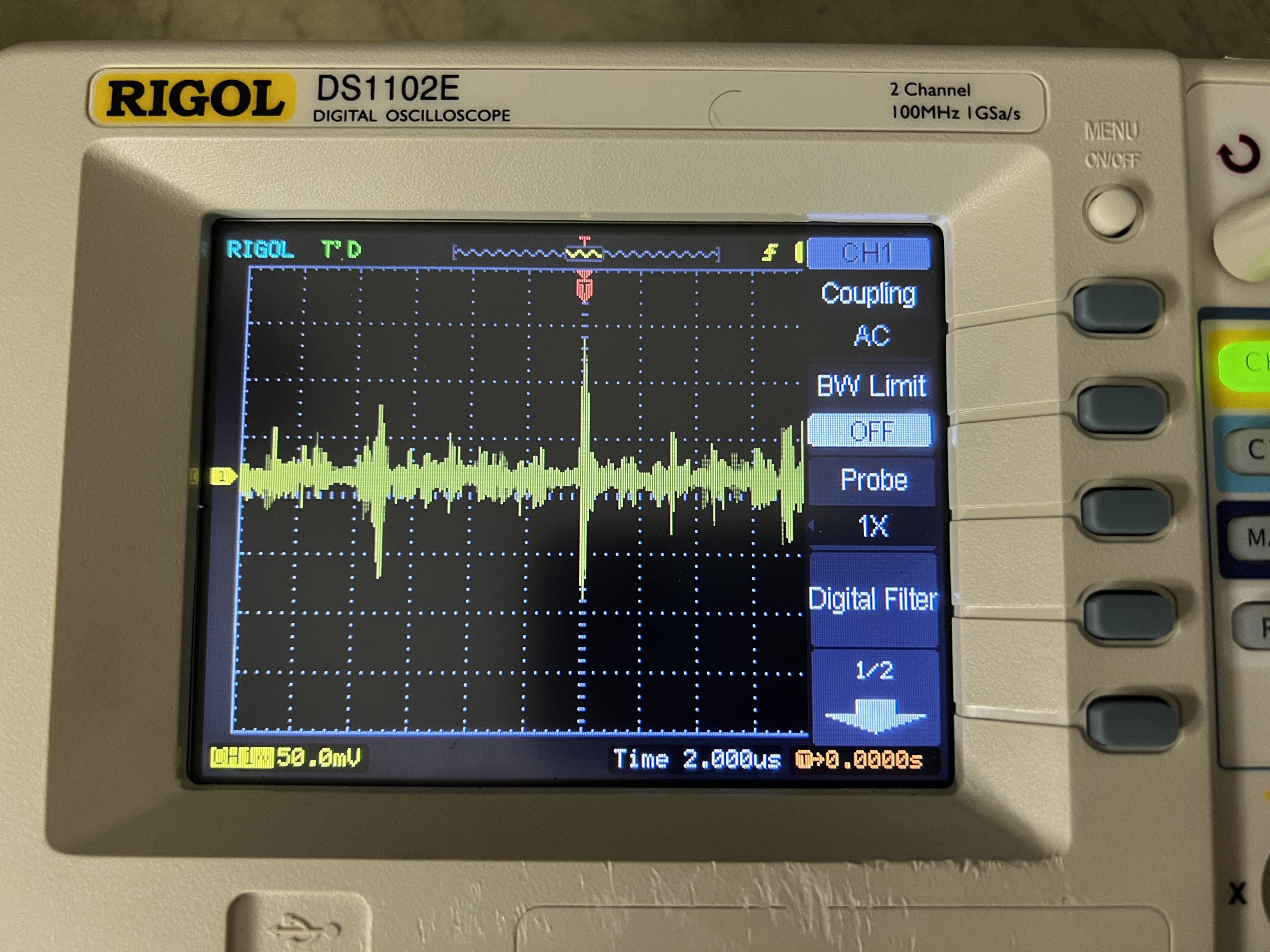
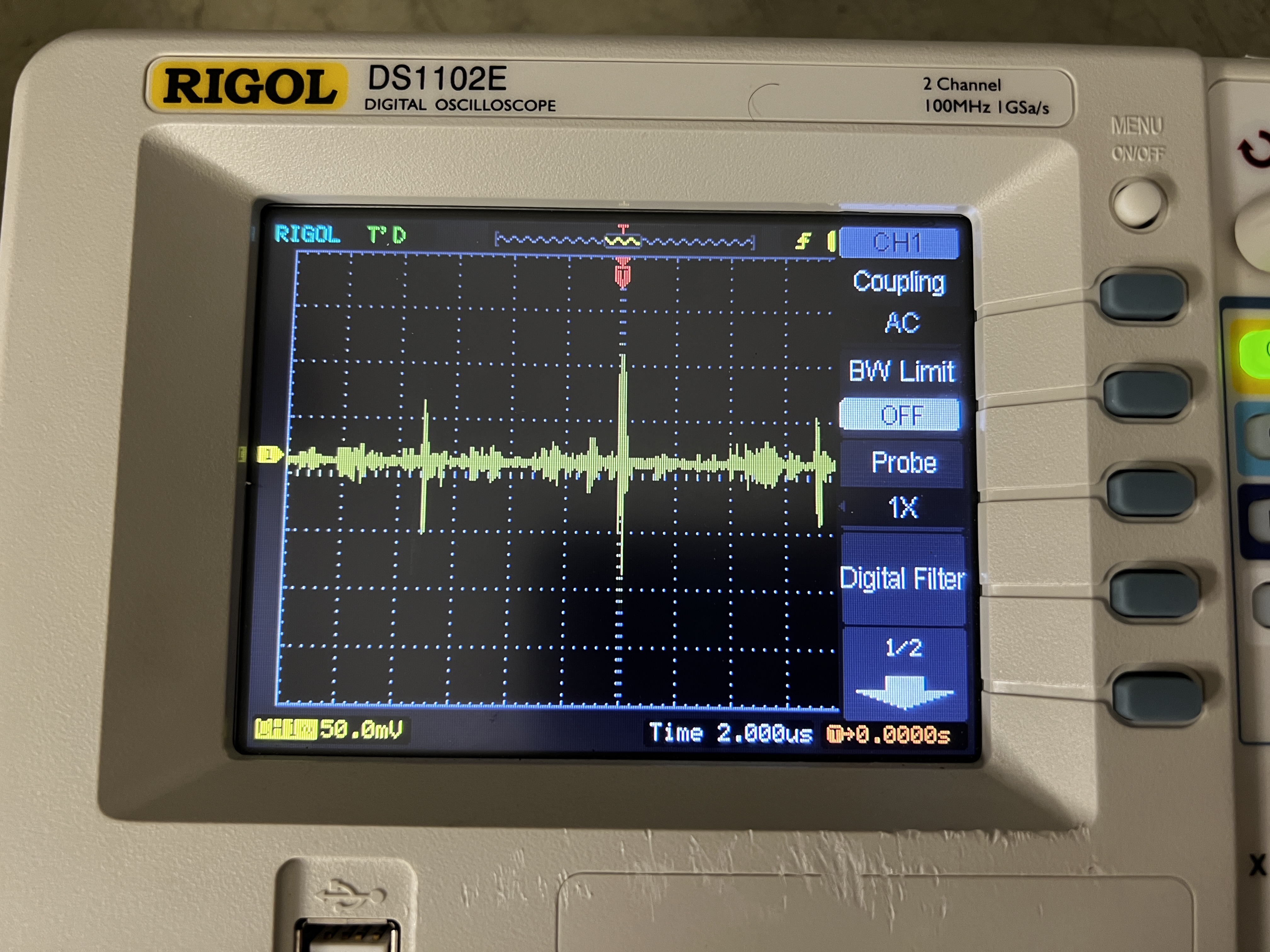
Photos of noise observed at each of the AIDA PSU outputs by digital oscillscope.
DAQ GOing with waveforms enabled.
Connection from AIDA PSU to scope by DMM test probes, twisted cabling, 3mm jack plug/BNC adaptor.
Attachment 1,2,3 = +5V
Attatchment 4 = -6V
Attatchment 5 = +7V
Attatchment 6 shows test setup
Repeat above test with *all* cables from AIDA PSU to FEE64s disconnected, i.e. no AIDA PSU load.
Attachment 7,8,9 = +5V
Attatchment 10 = -6V
Attatchment 11 = +7V |
| Attachment 1: IMG_8378.JPG
|
|
| Attachment 2: IMG_8380.JPG
|

|
| Attachment 3: IMG_8382.JPG
|

|
| Attachment 4: IMG_8384.JPG
|
|
| Attachment 5: IMG_8385.JPG
|

|
| Attachment 6: IMG_8387.JPG
|
|
| Attachment 7: IMG_8393.JPG
|
|
| Attachment 8: IMG_8392.JPG
|
|
| Attachment 9: IMG_8391.JPG
|
|
| Attachment 10: IMG_8390.JPG
|
|
| Attachment 11: IMG_8389.JPG
|

|
|
733
|
Tue Jun 10 13:29:23 2025 |
EW, CB, JM | Thresholds changed |
Experimented with slow comparator thresholds as we go down to lower beam energies
Checked deadlayer loses with SRIM, expected ruthford energies are as follows:
150keV/u -> 230keV
100keV/u -> 120keV
80keV/u -> 76keV
New thresholds:
aida1-4 0xc (120keV)
aida5-8 0x8 (80keV)
aida9-12 0x5 (50keV)
aida13-16 0x64(1MeV) set to MEC channel
Statistics and data rate with beam on but no target
Deleted April 24,25 and G22-86 from GSI, backup in Edinburgh |
| Attachment 1: Screenshot_from_2025-06-10_14-35-07.png
|

|
| Attachment 2: Screenshot_from_2025-06-10_14-34-59.png
|

|
| Attachment 3: Screenshot_from_2025-06-10_14-34-49.png
|

|
| Attachment 4: Screenshot_from_2025-06-10_14-34-17.png
|

|
|
557
|
Wed May 29 09:49:35 2024 |
JM, CB | Threshold changes / D+ beam |
09:00
R4 alpha background continues, currently R4_12
Temps OK, system checks unchanged from previous status (OK, aida16 clock and ADC issue)
10:30
R4 stopped and moved to the next run R5.
Lithium 3+ beam is not feasible at sufficient densities so we are switching to D+ at a beam energy of 0.75 MeV/u. A measurement of d+p at this energy would produce 3He at energies of ~900 keV.
The current threshold (slow comparator) has been 1 MeV (0x64). We lowered the thresholds in all FEE modules to 200 keV (0x14). ADC rates look fine in all FEEs (~tens of Hz) except in aida 15 and aida 16 which was ~several hundred kHz. Data rate to disk was 1.2 Mb/s
We increased the threshold in aida 15 and 16 only to 500 keV (0x32) and rates in aida 15 and 16 have dropped to <20 kHz. Data rate to disk now 220 kB/s.
11:00
R5 stopped. R6 started - background with reduced thresholds.
Attachment 1 - ADC data items statistics
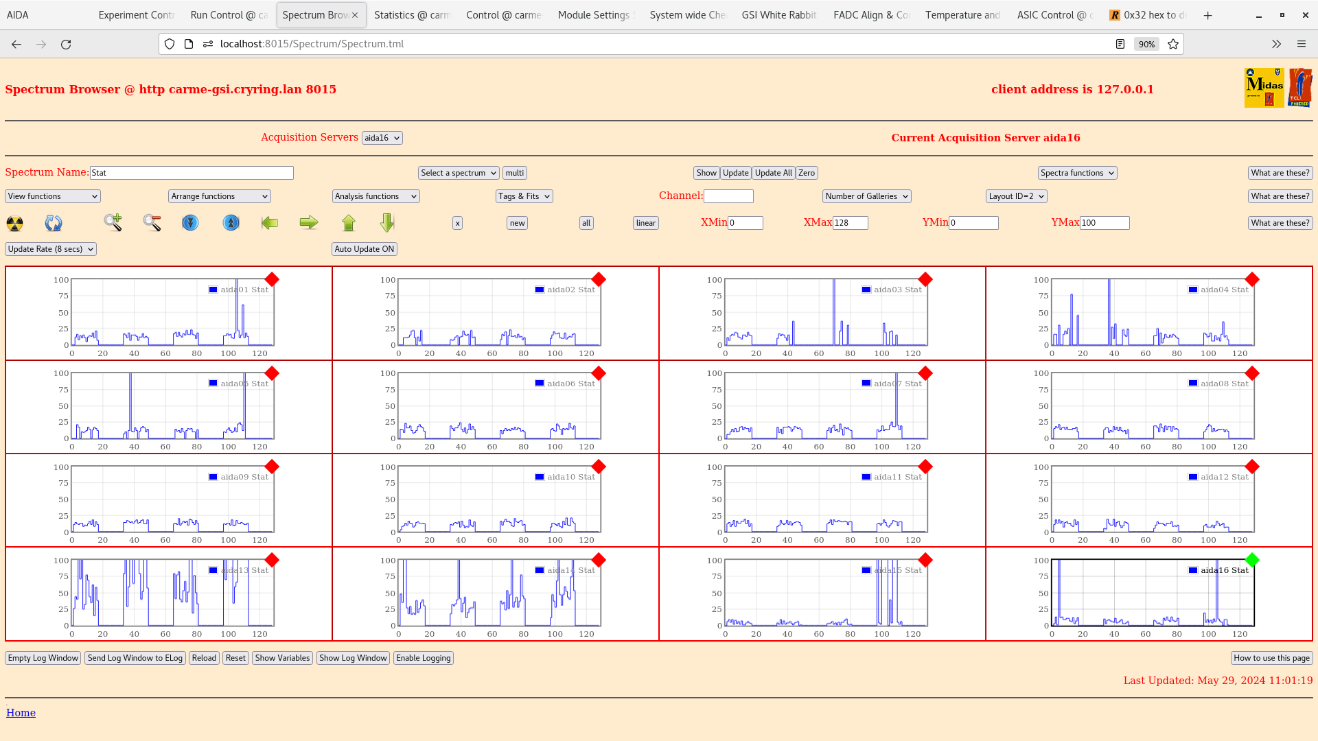
Attachment 2 - Histogram browser statistics
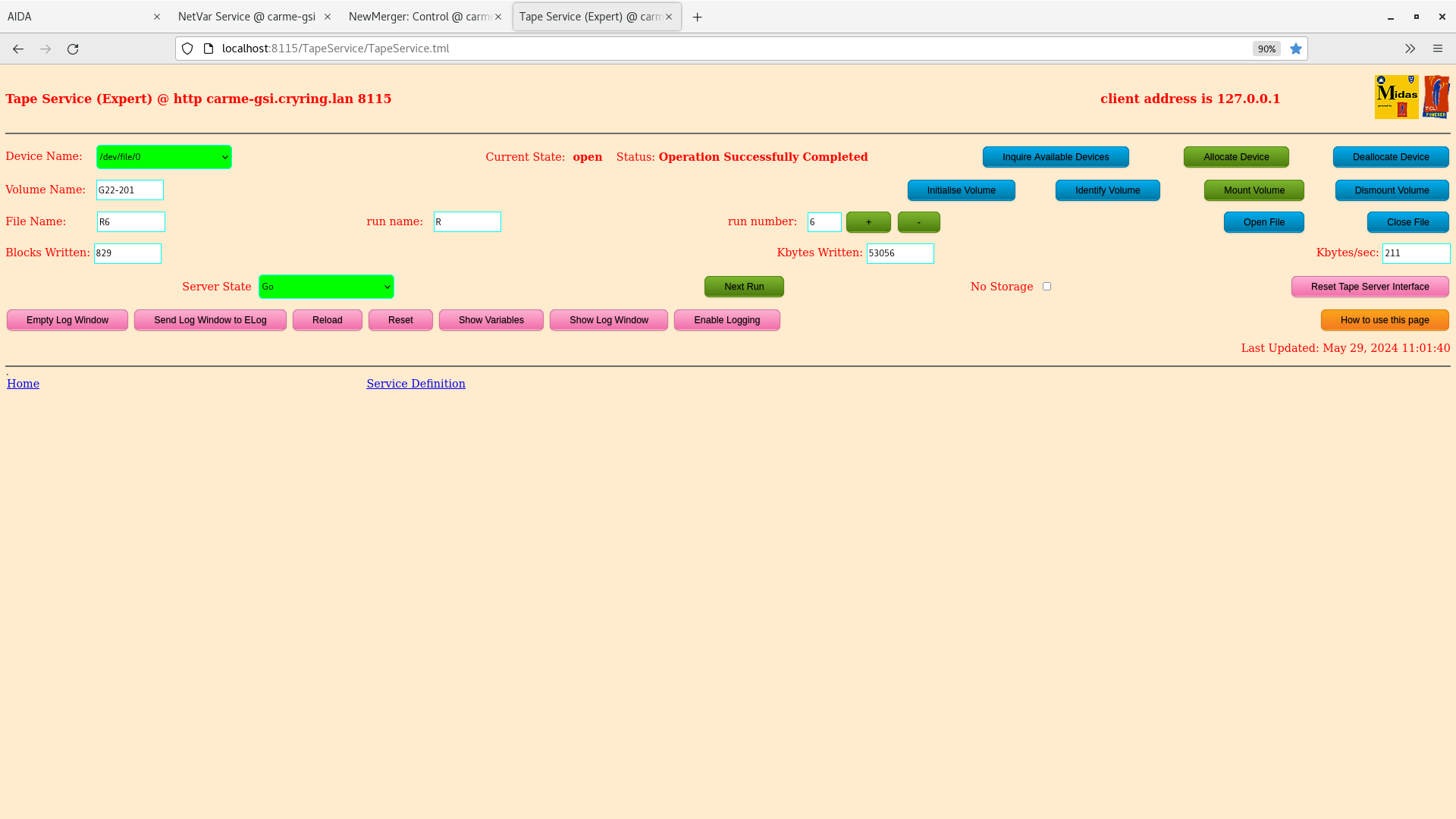
Attachment 3 - Tape server
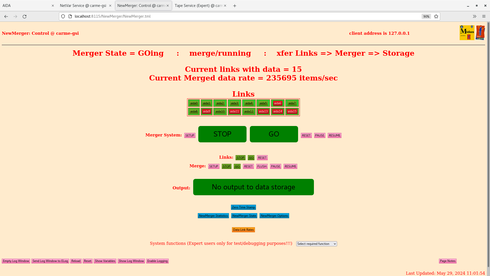
Attachment 4 - New Merger
13:12
R6 continues R6_9
Edits to the CARME sort code have been made. EyEx energy cut for online monitoring reduced to 100 keV. Multiplicity cut applies to lowEnergyEy, lowEnergyEx and lowEnergyXY histograms. Multiplicity cut considers only single strip events.
15:00
D+ beam is now in the ring and is being optimised by the beam operators. The CARME detectors are currently fullt out, but we can see some effects of the beam on the online monitoring code. |
| Attachment 1: Screenshot_from_2024-05-29_11-00-20.png
|

|
| Attachment 2: Screenshot_from_2024-05-29_11-01-30.png
|
|
| Attachment 3: Screenshot_from_2024-05-29_11-01-47.png
|
|
| Attachment 4: Screenshot_from_2024-05-29_11-02-03.png
|
|