| |
ID |
Date |
Author |
Subject |
|
|
526
|
Sun Mar 3 16:06:11 2024 |
TD | Sunday 3 March |
17.00 FEE64 41:a0:71 ASIC #2 u/s
      Replaced ASIC mezzanine with new ASIC mezzanine
      Installed as aida04

      Unable to boot nnrpi2 - manual/local control of BNC PB-5 and FEE64 PSU - no interlock

      Water temperature & pressure as measured outside S4 area - OK

      Manually power FEE64s

      BNC PB-5 local control/ON
      Amplitude 1.0V
      Attenuation x10
      Polarity -
      tau_d 1ms
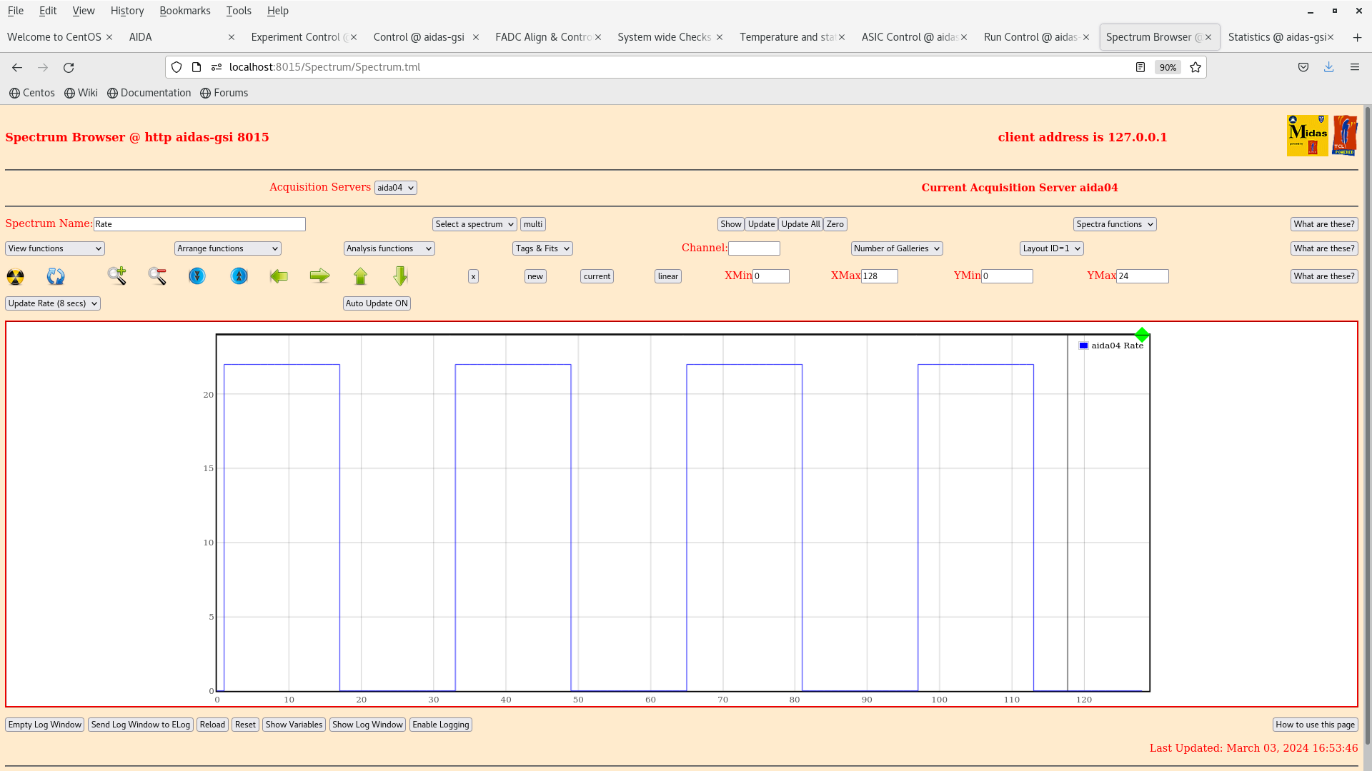
      Frequency 22Hz

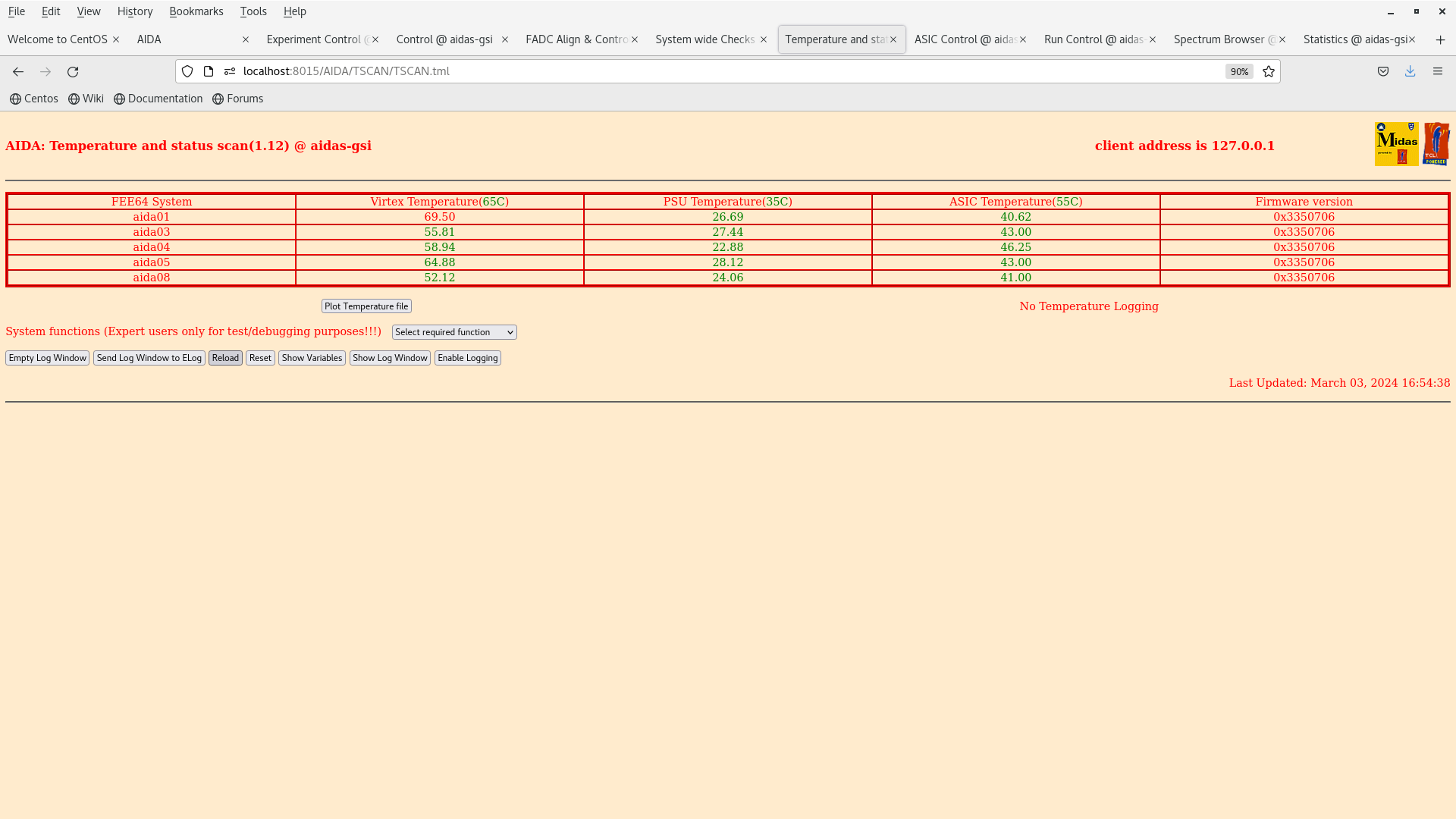
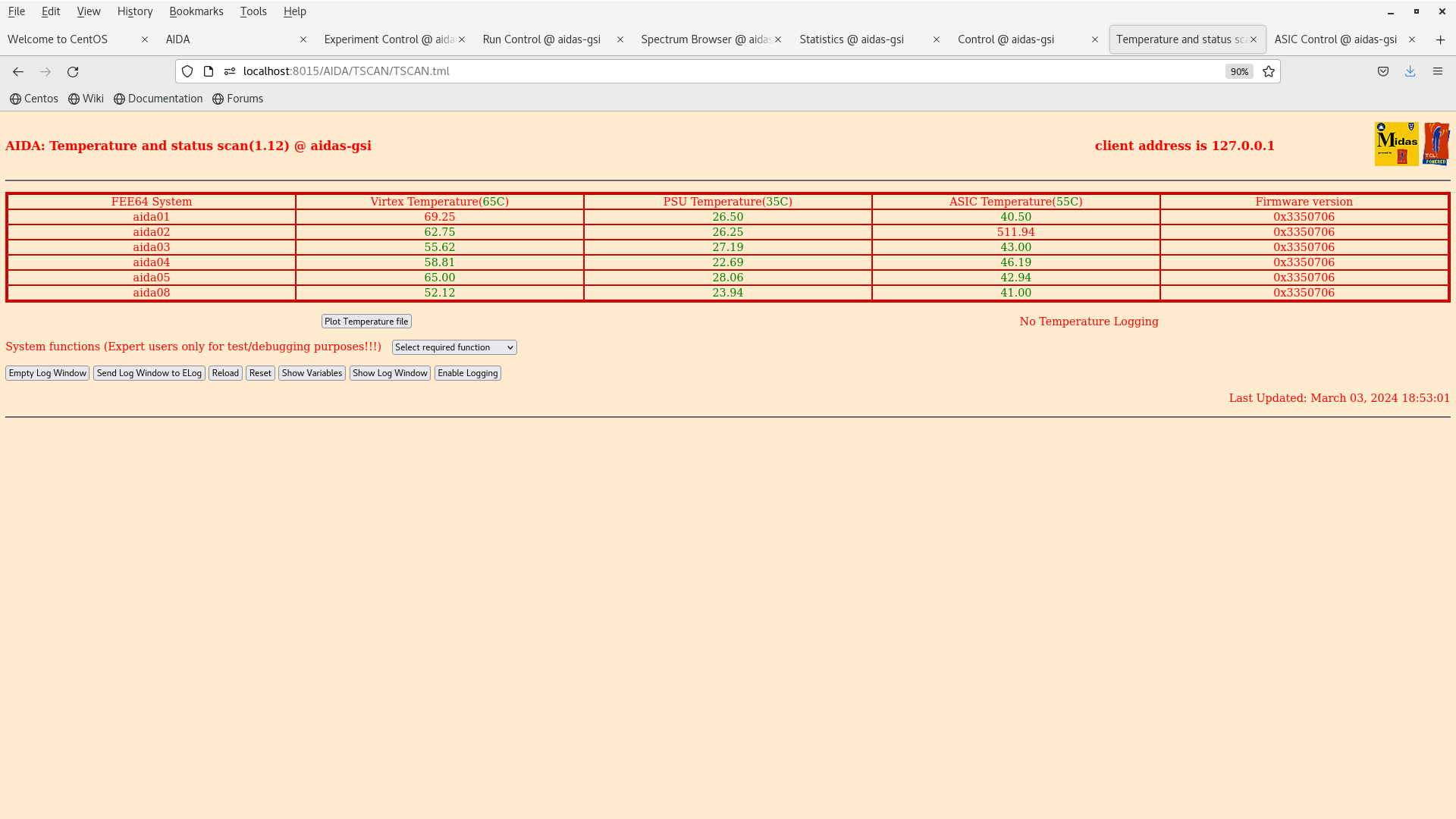
      FEE64 temps OK - attachment 1

      All system wide checks OK

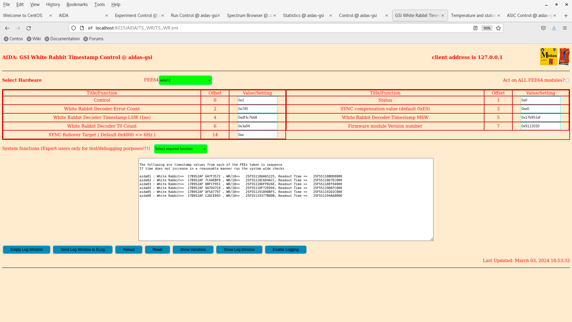
      WR timestamp OK - attachment 2

      aida04 ASIC settings - attachment 3

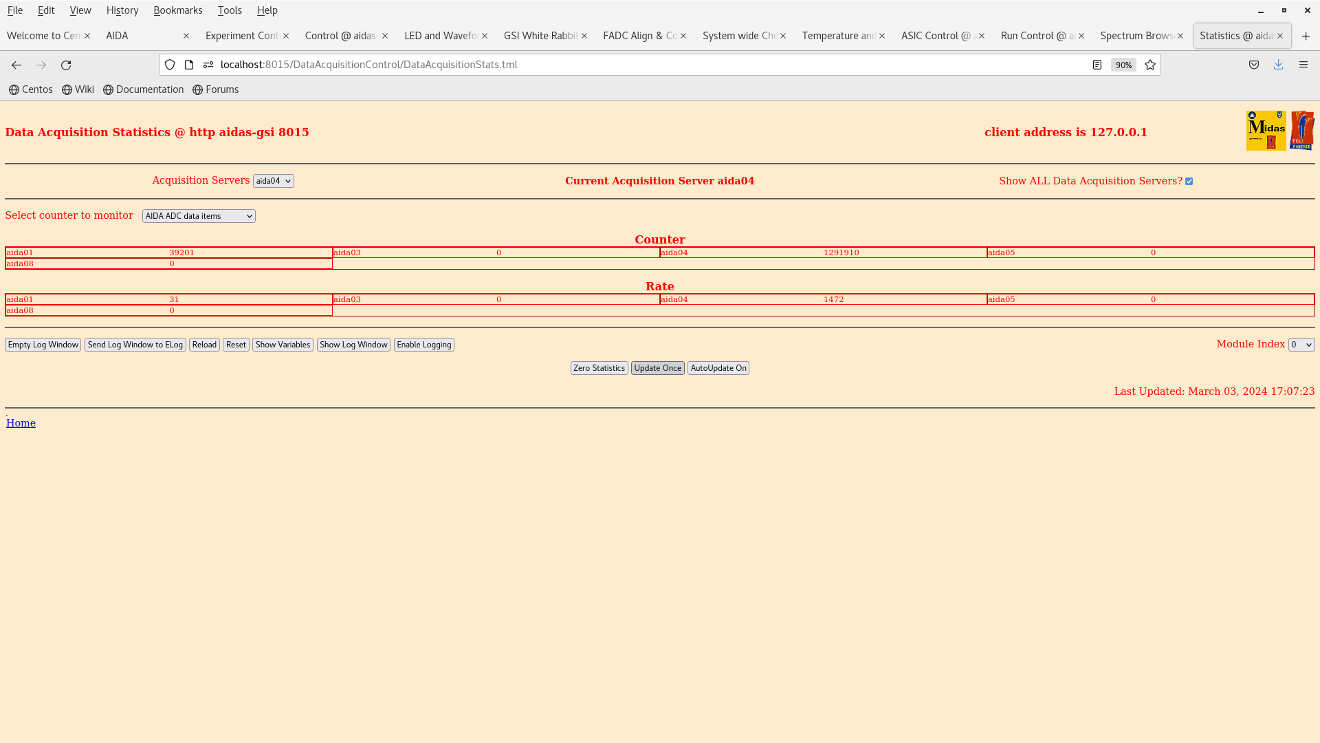
      ADC data item stats OK - attachment 4

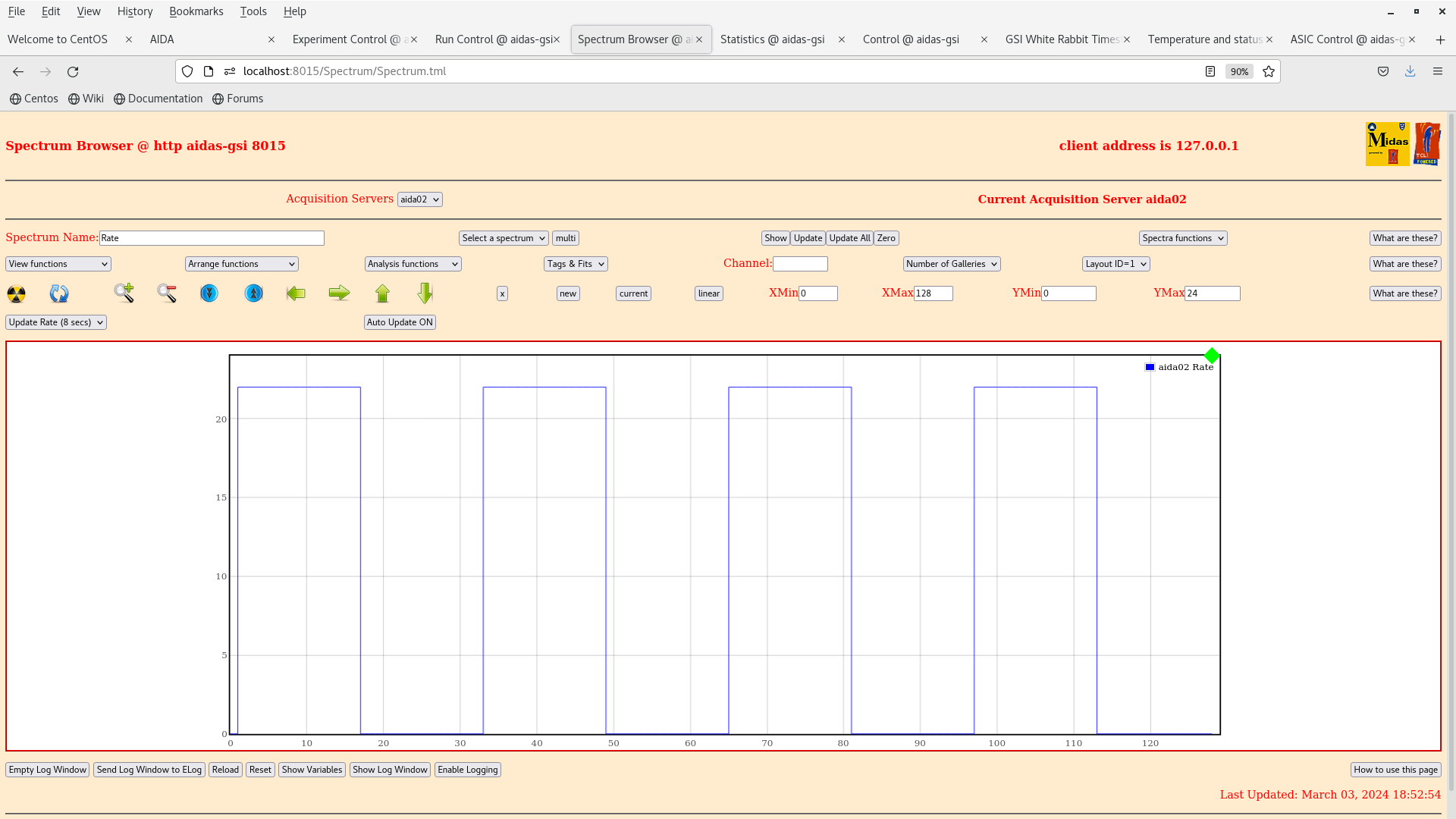
      aida04 Rate spectrum - attachment 5

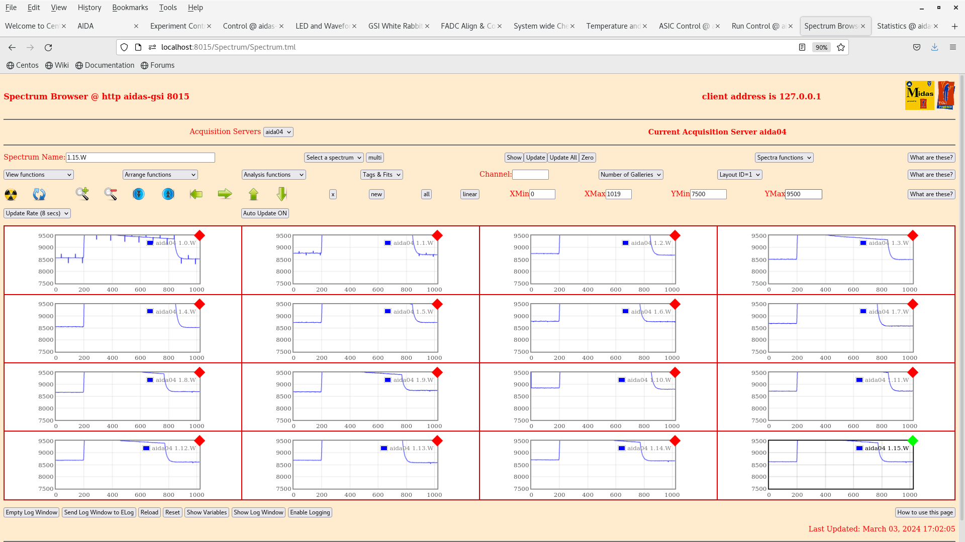
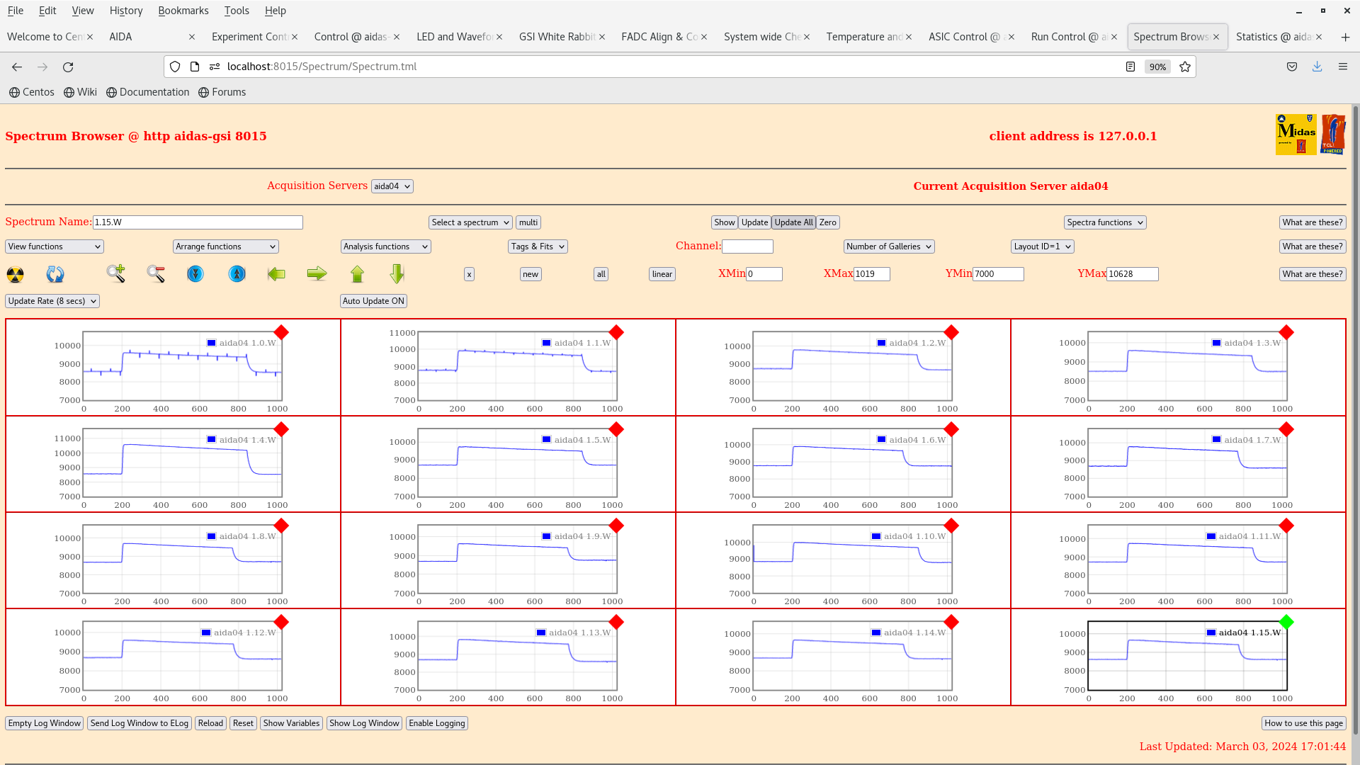
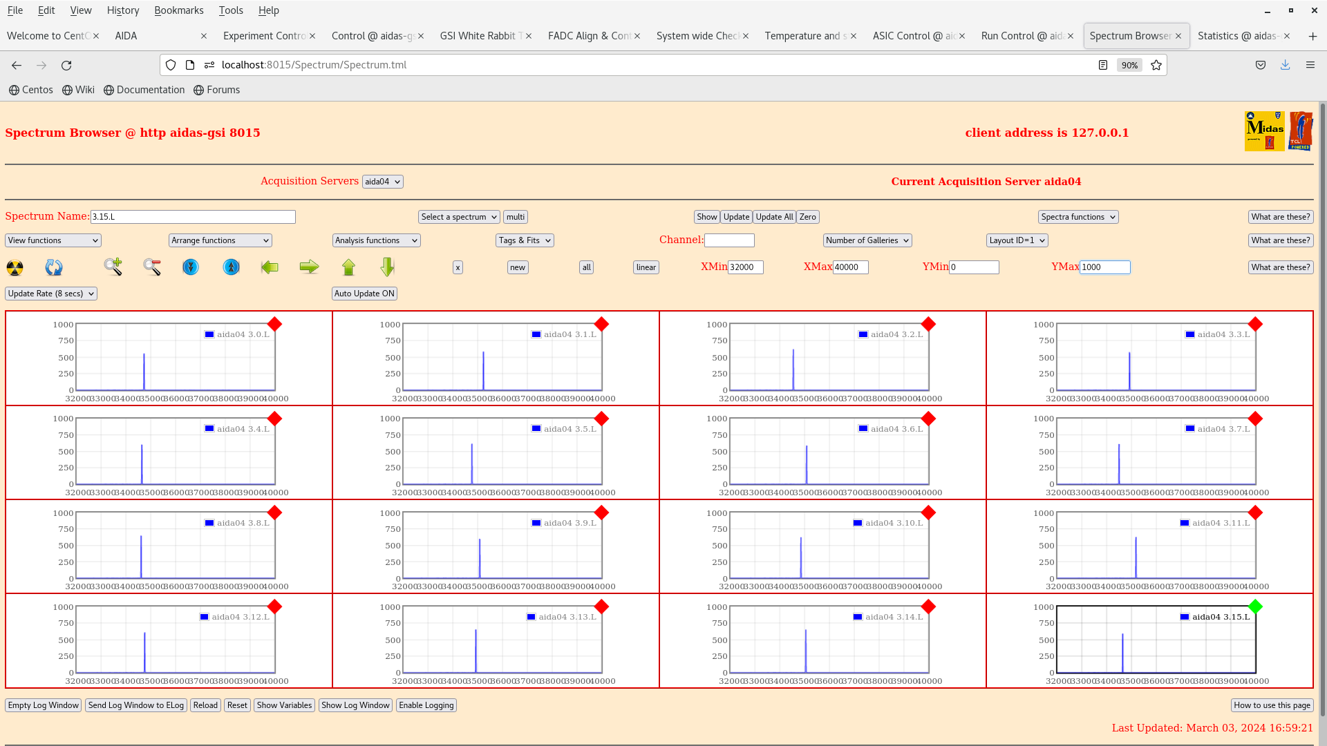
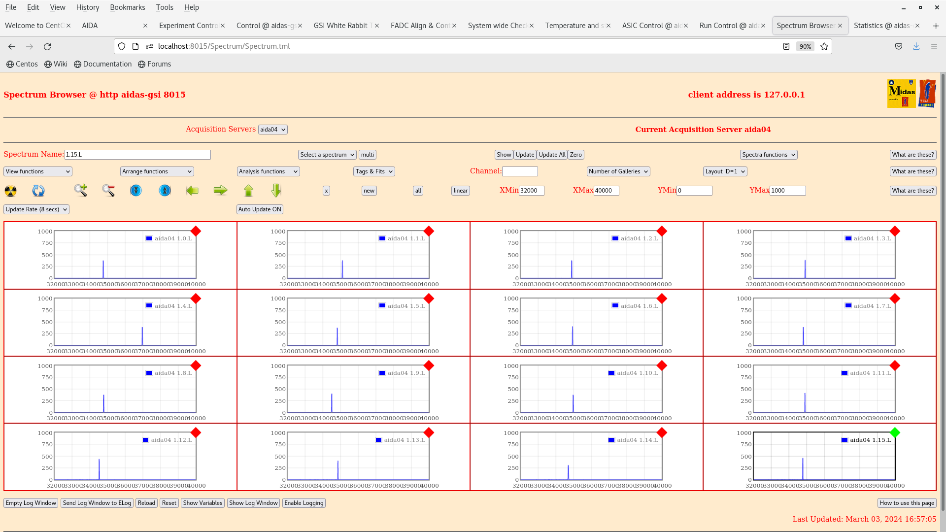
      aida04 *.*.L spectra - attachments 6-9
       1.8.L pulser peak width 15 ch FWHM

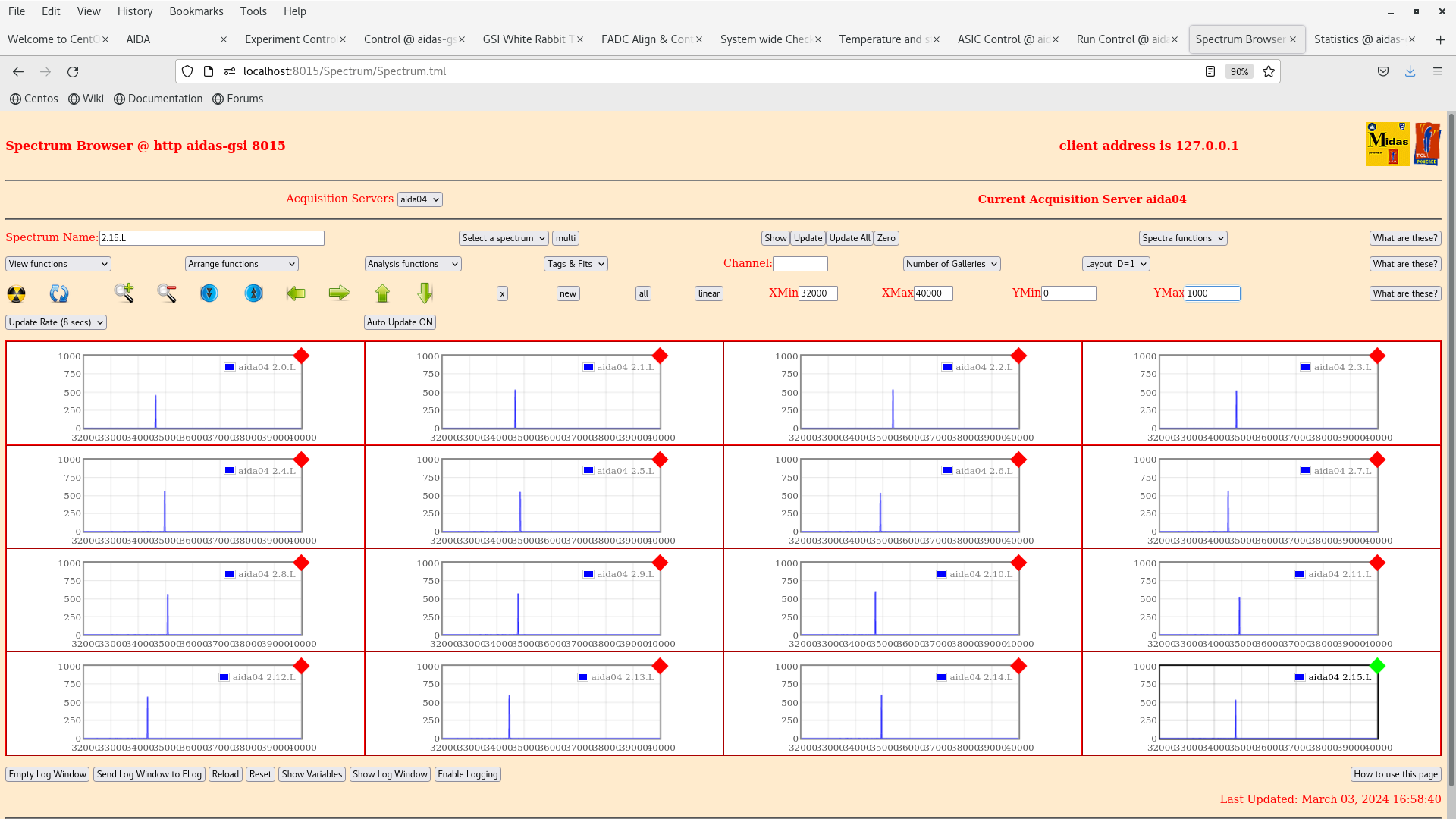
      aida04 1.8.W spectra - 20us FSR - attachment 10-11

      MIDAS configuration - attachment 12

      DHCP config - attachment 13


18.30 FEE64 41:f6:b7 ASIC #1 u/s
      Replaced ASIC mezzanine with new ASIC mezzanine
      Installed as aida02

      All system wide checks OK

      FEE64 temps - attachment 14
       aida02 ASIC temperature c. 512 deg C !
       PSU/Virtex temps OK
       Mezzanine ambient to touch - assume faulty sensor/poor connection?

      aida02 ASIC settings - attachment 15

      WR timestamp OK - attachment 16

      ADC data item stats OK - attachment 4

      aida04 Rate spectrum - attachment 18

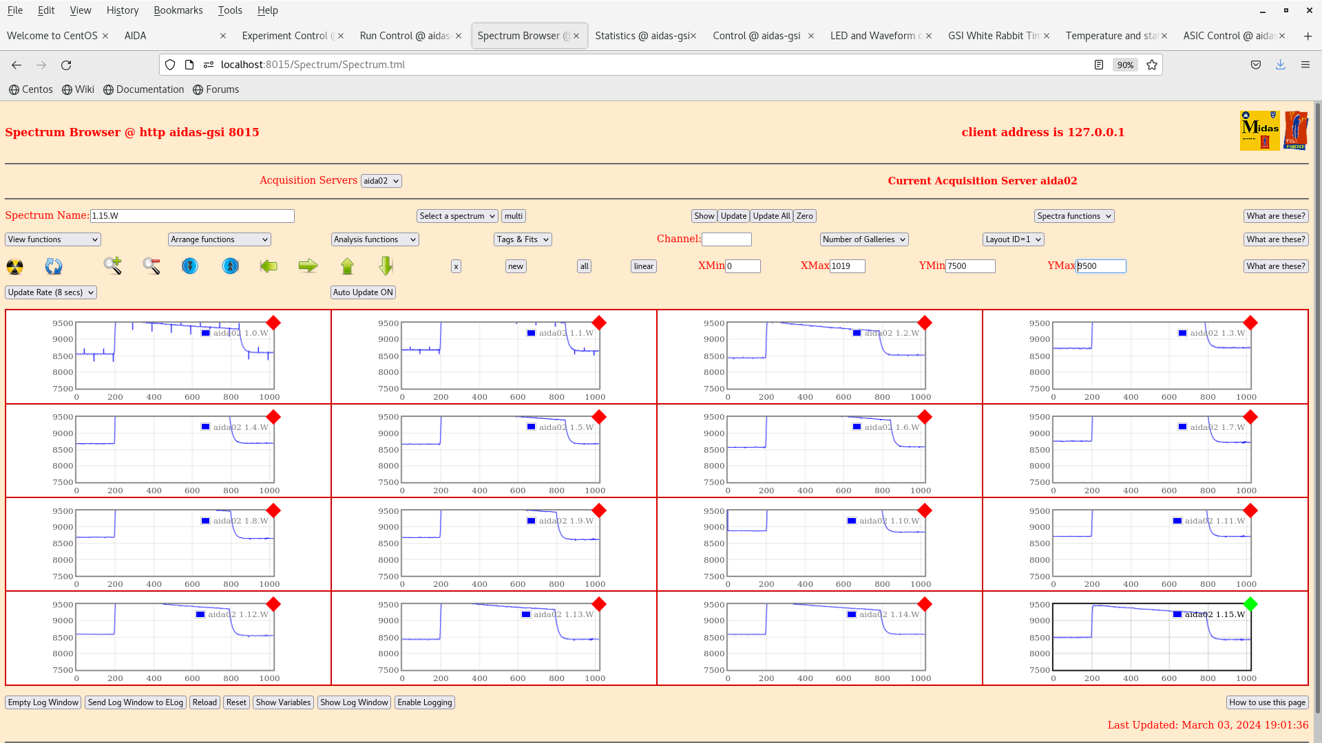
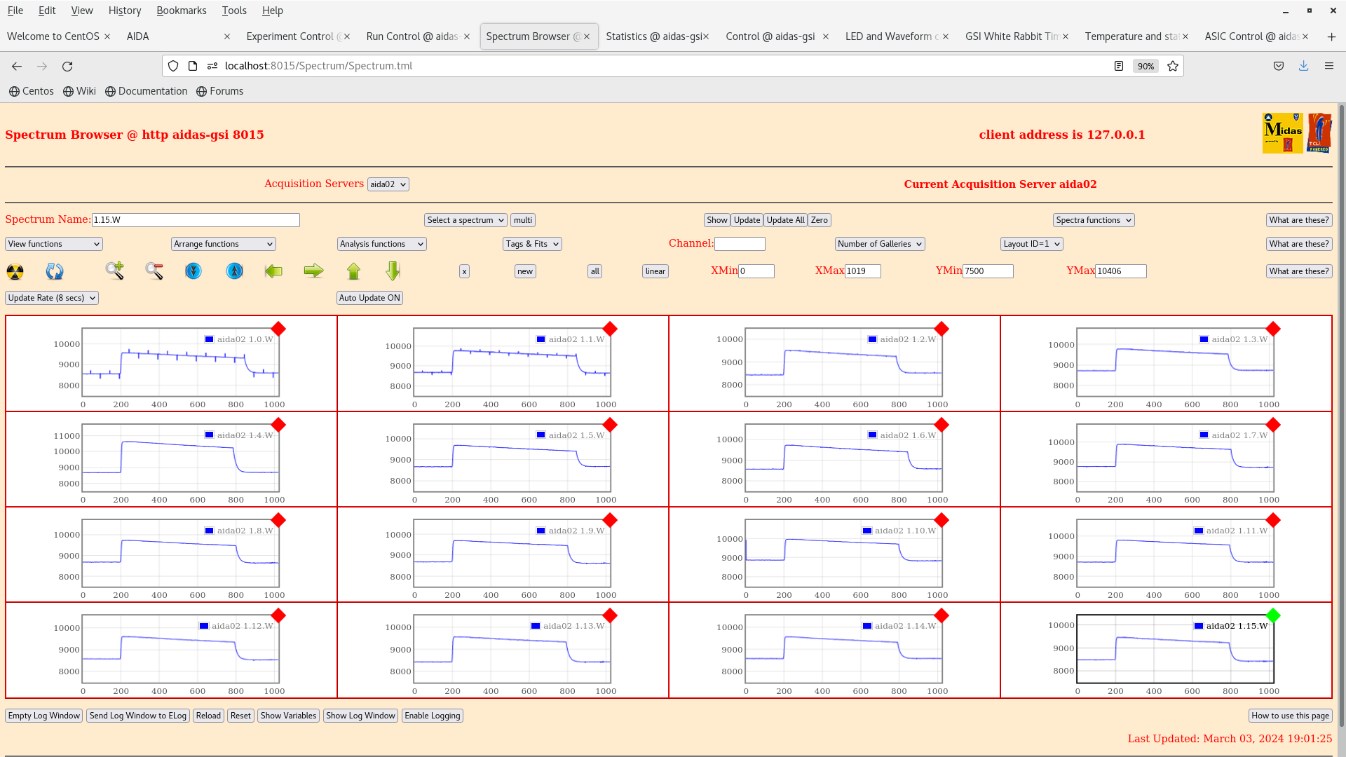
      aida02 1.8.W spectra - 20us FSR - attachment 19-20

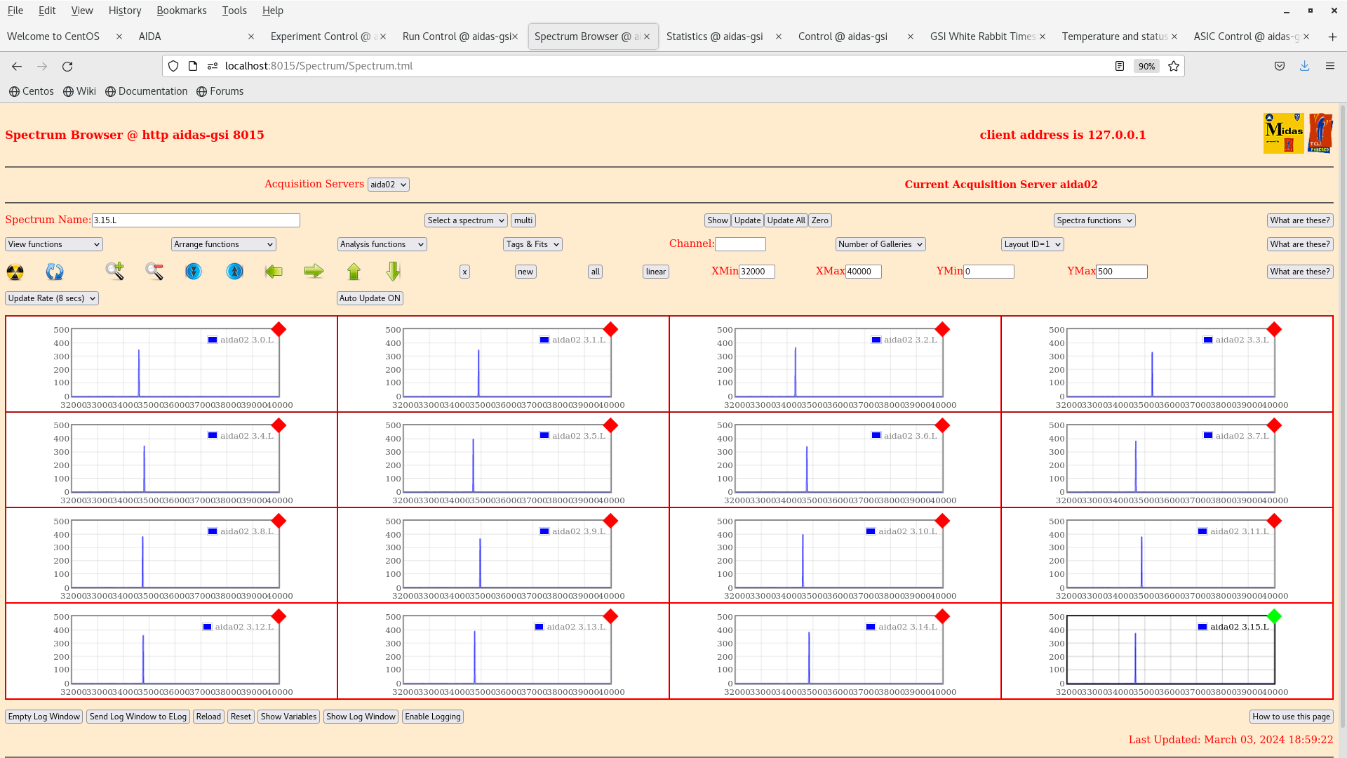
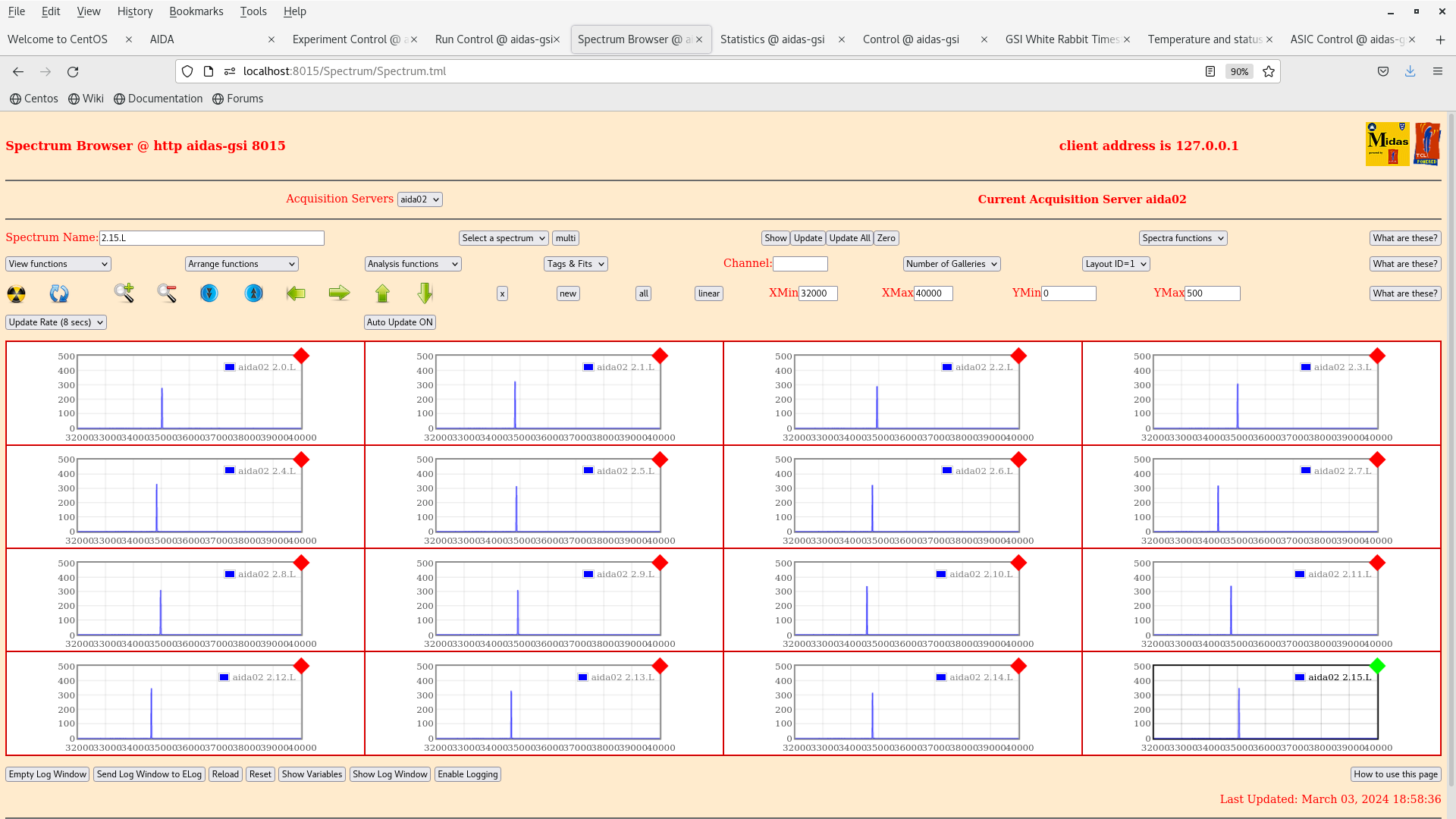
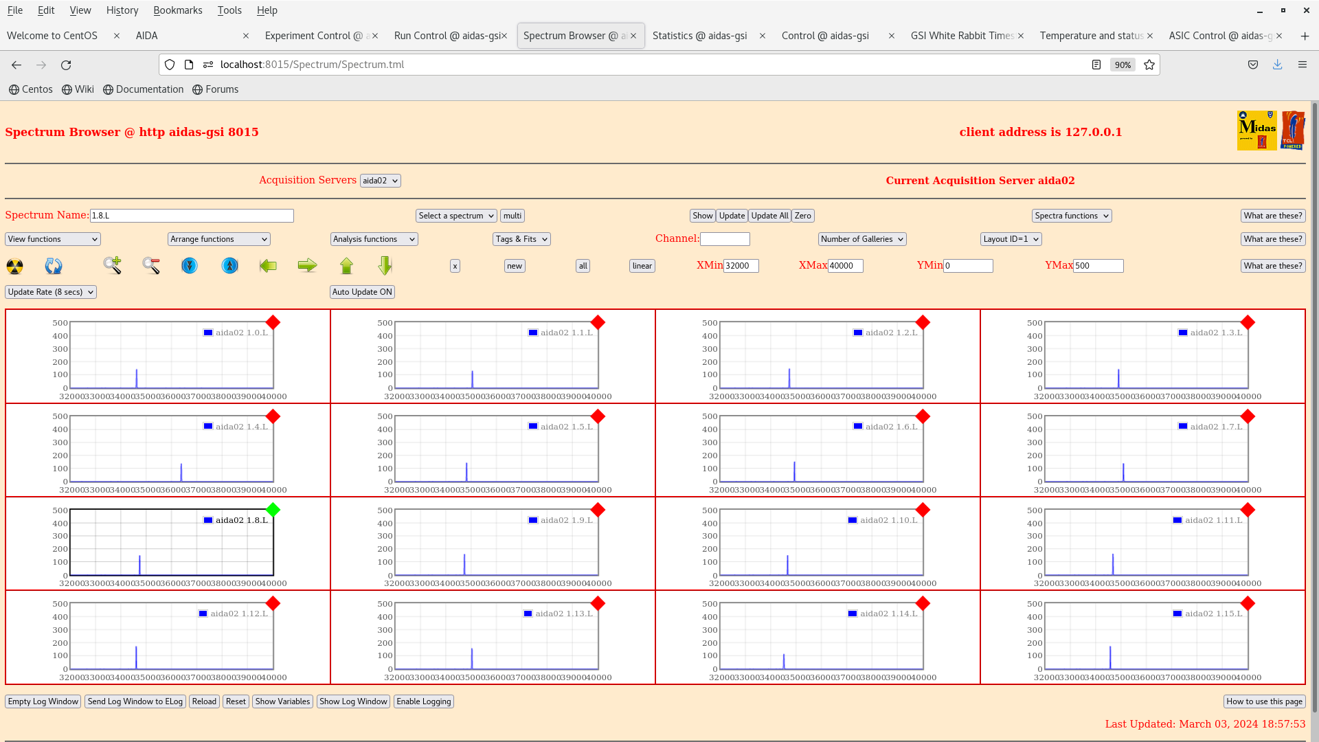
      aida02 *.*.L spectra - attachments 21-24
       1.8.L pulser peak width 16 ch FWHM


19.30 Power OFF
|
| Attachment 1: Screenshot_from_2024-03-03_16-54-42.png
|
|
| Attachment 2: Screenshot_from_2024-03-03_16-55-14.png
|

|
| Attachment 3: Screenshot_from_2024-03-03_16-55-21.png
|

|
| Attachment 4: Screenshot_from_2024-03-03_17-07-26.png
|
|
| Attachment 5: Screenshot_from_2024-03-03_16-53-52.png
|
|
| Attachment 6: Screenshot_from_2024-03-03_17-02-09.png
|
|
| Attachment 7: Screenshot_from_2024-03-03_17-01-52.png
|
|
| Attachment 8: Screenshot_from_2024-03-03_17-00-18.png
|

|
| Attachment 9: Screenshot_from_2024-03-03_16-59-23.png
|
|
| Attachment 10: Screenshot_from_2024-03-03_16-58-43.png
|
|
| Attachment 11: Screenshot_from_2024-03-03_16-57-09.png
|
|
| Attachment 12: startup.tcl
|
   Setting BGColor "BlanchedAlmond"
   Setting TextColor "red"

      Setting ProjectName  AIDA
      Setting ProjectImage AIDA.gif
      Setting ProjectURL   "http://npg.dl.ac.uk/NPG/Projects/Fair.html"


  Setting Option1Name STFC
  Setting Option1URL  "stfc.ac.uk"
  Setting Option1Image stfc.jpg


# global MessageLoggerServerHost
#  set  MessageLoggerServerHost nndhcp077.dl.ac.uk

#    package require  MessageLoggerClient

#  Setting Option3Name "Elog Server"
#  Setting Option3URL  "http://nndhcp077.dl.ac.uk:8080/DataAcq/"

#    Install required services

    if {![namespace exists ::AIDA]} {namespace eval ::AIDA {puts "created namespace ::AIDA"}}
#    set ::AIDA::TestMode 1

    global SpectrumServerHost
    set SpectrumServerHost aidas

   package require XAIDAAccessClient  ;# for Client end - ie AIDA server workstation  sets MIDAS_XAIDAAccessClient_Exists (SOAP)

   package require XAD9252AccessClient ;# for Client end - ie AIDA server workstation  sets MIDAS_XAD9252AccessClient_Exists (SOAP)

namespace eval DataAcquisition {
     variable PROJECT AIDA
     variable ACQSERVERS
     set ACQSERVERS [list aida01 aida03 aida04 aida05 aida08]
     variable ACQSERVER [first $ACQSERVERS]
     variable DataTransferStreams; set DataTransferStreams 2
#     set ::DataAcquisition::EnableMerger 1
#     set ::DataAcquisition::EnableTape 1
    variable RDOGo 0
}

namespace eval AIDA {
      variable ModuleMenu; set ModuleMenu $::DataAcquisition::ACQSERVERS
      variable TSMaster; set TSMaster aida01
      variable FEE64 [first $ModuleMenu]
      variable ConfigBase; set ConfigBase [file join $env(MIDASBASE) config TclHttpd]
}

    Setting DataBaseRoot "/MIDAS/DB"
    package require DataBaseAccessServer

    package require NetVarsServer 1.1
    package require SigTaskServer

#    package require MemSasServer

#    Install services for Run Control

namespace eval $::DataAcquisition::PROJECT {
    variable DBRootName [file join EXPERIMENTS AIDA]
    variable DBNodeBase 2012
}

  package require AIDARunControl
#  package require TapeServer
#  package require MergerControl
#  package require MERGERunControl


  Setting Option7Name "Project Home Page"
  Setting Option7URL  "http://npg.dl.ac.uk/NPG/Projects/Fair.html"

  Setting Option8Name "Server Software Home Page"
  Setting Option8URL  "http://npg.dl.ac.uk/MIDAS/download/WebServices.html"
|
| Attachment 13: dhcpd.conf
|
#
# DHCP Server Configuration file.
#   see /usr/share/doc/dhcp*/dhcpd.conf.sample
#
# Date of last update  Jan 12 2015
#
authoritative;

ddns-update-style none; ddns-updates off;

# 2 days
#default-lease-time 172800;
# 4 days
default-lease-time 345600;
# 8 days
max-lease-time 691200;

option domain-search code 119 = string;

option domain-name "dl.ac.uk";
option domain-name-servers 193.62.115.16, 148.79.80.78;
option netbios-name-servers 148.79.160.89;
option netbios-node-type 8;
option nis-domain "nuclear.physics";
option nis-servers 193.62.115.77;


subnet 192.168.11.0 netmask 255.255.255.0 {
   option subnet-mask 255.255.255.0;
   option broadcast-address 192.168.11.255;
   pool {
 range 192.168.11.118 192.168.11.199;
   }
}

group {
   use-host-decl-names true;
   default-lease-time 3600;
   max-lease-time 14400;

   server-name "192.168.11.99";
   next-server 192.168.11.99;

   host nnrpi1 {
     hardware ethernet b8:27:eb:bb:46:7b;
     fixed-address 192.168.11.251;
   }

   host nnrpi2 {
     hardware ethernet b8:27:eb:40:53:e8;
     fixed-address 192.168.11.117;
   }

   host edinburgh {
      hardware ethernet 00:14:4f:9b:6e:7a;
      fixed-address 192.168.11.118;
   }

   host aida01 {
     hardware ethernet d8:80:39:41:ba:8a;
     fixed-address 192.168.11.1;
    option root-path "/home/Embedded/XilinxLinux/ppc_4xx/rfs/aida01";
   }

   host aida02 {
     hardware ethernet d8:80:39:41:ba:22;
     fixed-address 192.168.11.2;
    option root-path "/home/Embedded/XilinxLinux/ppc_4xx/rfs/aida02";
   }

   host aida03 {
     hardware ethernet d8:80:39:41:d8:21;
     fixed-address 192.168.11.3;
    option root-path "/home/Embedded/XilinxLinux/ppc_4xx/rfs/aida03";
   }

   host aida04 {
     hardware ethernet d8:80:39:41:a0:71;
     fixed-address 192.168.11.4;
    option root-path "/home/Embedded/XilinxLinux/ppc_4xx/rfs/aida04";
   }


   host aida05 {
     hardware ethernet d8:80:39:41:ee:10;
     fixed-address 192.168.11.5;
    option root-path "/home/Embedded/XilinxLinux/ppc_4xx/rfs/aida05";
   }

   host aida06 {
     hardware ethernet d8:80:39:41:cf:ac;
     fixed-address 192.168.11.6;
    option root-path "/home/Embedded/XilinxLinux/ppc_4xx/rfs/aida06";
   }

   host aida07 {
     hardware ethernet d8:80:39:41:f6:5a;
     fixed-address 192.168.11.7;
    option root-path "/home/Embedded/XilinxLinux/ppc_4xx/rfs/aida07";
   }

   host aida08 {
     hardware ethernet d8:80:39:41:ba:89;
     fixed-address 192.168.11.8;
    option root-path "/home/Embedded/XilinxLinux/ppc_4xx/rfs/aida08";
   }

   host aida09 {
     hardware ethernet d8:80:39:42:0d:15;
     fixed-address 192.168.11.9;
    option root-path "/home/Embedded/XilinxLinux/ppc_4xx/rfs/aida09";
   }

   #host aida06 {
   #  hardware ethernet d8:80:39:41:ee:72;
   #  fixed-address 192.168.11.6;
   # option root-path "/home/Embedded/XilinxLinux/ppc_4xx/rfs/aida06";
   #}

   #host aida07 {
   #  hardware ethernet d8:80:39:41:b4:0c;
   #  fixed-address 192.168.11.7;
   # option root-path "/home/Embedded/XilinxLinux/ppc_4xx/rfs/aida07";
   #}

   #host aida08 {
   #  hardware ethernet d8:80:39:41:ba:2b;
   #  fixed-address 192.168.11.8;
   # option root-path "/home/Embedded/XilinxLinux/ppc_4xx/rfs/aida08";
   #}

   #host aida13 {
   #  hardware ethernet d8:80:39:42:d:15;
   #  fixed-address 192.168.11.13;
   # option root-path "/home/Embedded/XilinxLinux/ppc_4xx/rfs/aida13";
   #}

#   host aida14 {
#     hardware ethernet d8:80:39:42:d:b;
#     fixed-address 192.168.11.14;
#    option root-path "/home/Embedded/XilinxLinux/ppc_4xx/rfs/aida14";
#   }

   #host aida05 {
   #  hardware ethernet d8:80:39:41:ee:10;
   #  fixed-address 192.168.11.5;
   # option root-path "/home/Embedded/XilinxLinux/ppc_4xx/rfs/aida05";
   #}

   #host aida14 {
   #  hardware ethernet d8:80:39:41:f6:ed;
   #  fixed-address 192.168.11.14;
   # option root-path "/home/Embedded/XilinxLinux/ppc_4xx/rfs/aida14";
   #}
}


subnet 192.168.12.0 netmask 255.255.255.0 {
   option subnet-mask 255.255.255.0;
   option broadcast-address 192.168.12.255;
   pool {
 range 192.168.12.100 192.168.12.199;
   }
}

group {
   use-host-decl-names true;
   default-lease-time 3600;
   max-lease-time 14400;

   server-name "192.168.12.99";
   next-server 192.168.12.99;


}
|
| Attachment 14: Screenshot_from_2024-03-03_18-53-03.png
|
|
| Attachment 15: Screenshot_from_2024-03-03_18-53-16.png
|

|
| Attachment 16: Screenshot_from_2024-03-03_18-53-41.png
|
|
| Attachment 17: Screenshot_from_2024-03-03_19-02-33.png
|

|
| Attachment 18: Screenshot_from_2024-03-03_18-53-47.png
|
|
| Attachment 19: Screenshot_from_2024-03-03_19-01-41.png
|
|
| Attachment 20: Screenshot_from_2024-03-03_19-01-31.png
|
|
| Attachment 21: Screenshot_from_2024-03-03_19-00-11.png
|

|
| Attachment 22: Screenshot_from_2024-03-03_18-59-24.png
|
|
| Attachment 23: Screenshot_from_2024-03-03_18-58-39.png
|
|
| Attachment 24: Screenshot_from_2024-03-03_18-57-57.png
|
|
|
|
525
|
Mon Feb 26 13:17:51 2024 |
TD | Offline analysis of DEC23/R9_6 |
First pass analysis of data file /TapeData/DEC23/R9_6

 *** TDR format 3.3.0 analyser - TD - May 2021
 *** ERROR: READ I/O error:       5002
                   blocks:      32000
          ADC data format:  234532726 (   99567.1 Hz)
        Other data format:   27387282 (   11626.8 Hz)
 Sample trace data format:          0 (       0.0 Hz)
         Undefined format:          0 (       0.0 Hz)
   Other data format type:      PAUSE:         53 (       0.0 Hz)
                               RESUME:         53 (       0.0 Hz)
                              SYNC100:      40775 (      17.3 Hz)
                              WR48-63:      40775 (      17.3 Hz)
                           FEE64 disc:    2928025 (    1243.0 Hz)
                             MBS info:   24377601 (   10349.1 Hz)
                           Other info:          0 (       0.0 Hz)

   ADC data range bit set:     287073 (     121.9 Hz)

                Timewarps:        ADC:          0 (       0.0 Hz)
                                PAUSE:          0 (       0.0 Hz)
                               RESUME:          0 (       0.0 Hz)
                              SYNC100:          0 (       0.0 Hz)
                              WR48-63:          0 (       0.0 Hz)
                           FEE64 disc:          0 (       0.0 Hz)
                             MBS info:          0 (       0.0 Hz)
                            Undefined:          0 (       0.0 Hz)
                         Sample trace:          0 (       0.0 Hz)

 *** Timestamp elapsed time:     2355.524 s

 *** Statistics
 FEE  ADC Data Other Data     Sample  Undefined      Pause     Resume    SYNC100    WR48-63       Disc        MBS      Other   HEC Data
  0   59013868     372005          0          0         20         20       9888       9888     281563      70626          0      55467
  1   31445079    1098714          0          0          2          2       5017       5017     243009     845667          0      38876
  2   22895499   11841669          0          0          1          1       5294       5294     482655   11348424          0      42748
  3   18228498   11705354          0          0          0          0       3913       3913     416619   11280909          0      78526
  4   25500772    1237178          0          0          3          3       4320       4320     396557     831975          0      28918
  5          4          0          0          0          0          0          0          0          0          0          0          0
  6   15933921     394210          0          0          0          0       2560       2560     389090          0          0      11489
  7   61515085     738152          0          0         27         27       9783       9783     718532          0          0      31049

FEE64 configuration https://elog.ph.ed.ac.uk/AIDA/935


Note

- aida06 not connected to DSSSD ( cabling broken  - will be replaced later this week )

- LEC ( 20MeV FSR ) data ADC offset corrected
   ADC offsets available for 489 of 512 channels and are included in the analysis - 23 strips for which no ADC offsets could be calculated ( usually because there was
no
pulser data ) are not included in analysis
- LEC ( 20MeV FSR ) front-back strip energy difference cut +/- 50 channels ( c. +/- 280keV )
- HEC ( 2GeV FSR ) front-back strip energy difference cut +/-200 channels ( c. +/- 1120MeV )

- LEC ADC data: 13 < channel < 188 ( c. 73-1053keV )
- HEC ADC data: > 13 channels ( c. 73MeV )
- FEE64 hardware thresholds: LEC c. 100keV, HEC c. 200MeV


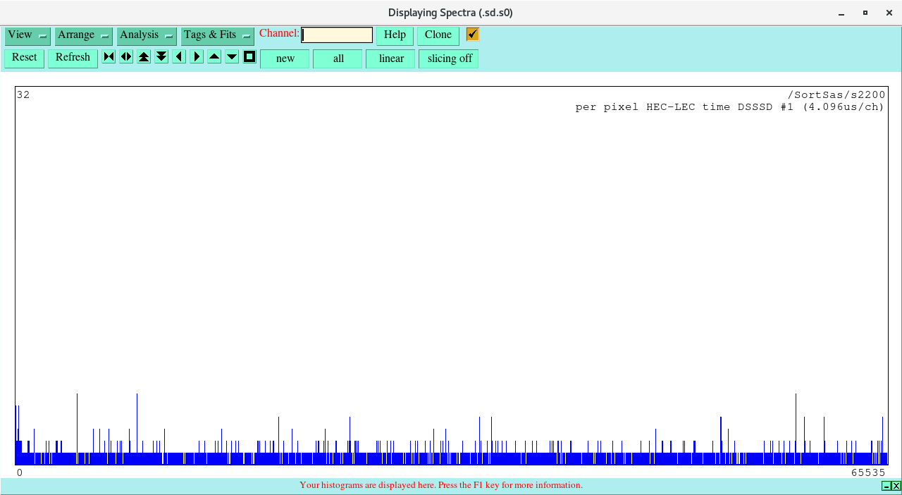
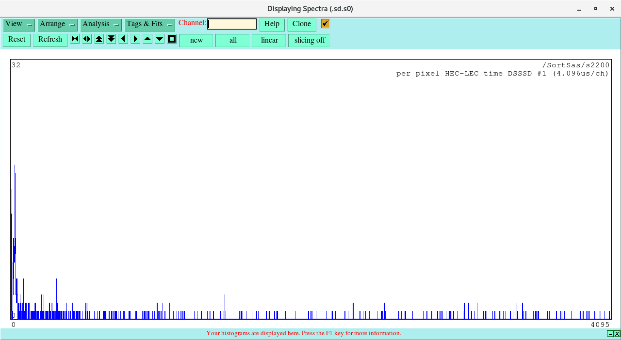
Attachments 1 & 2 - per pixel HEC-LEC event time difference spectra - 4.096us/channel

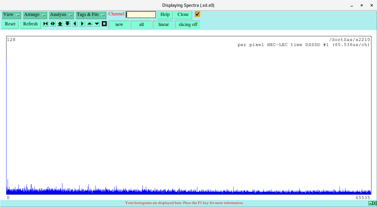
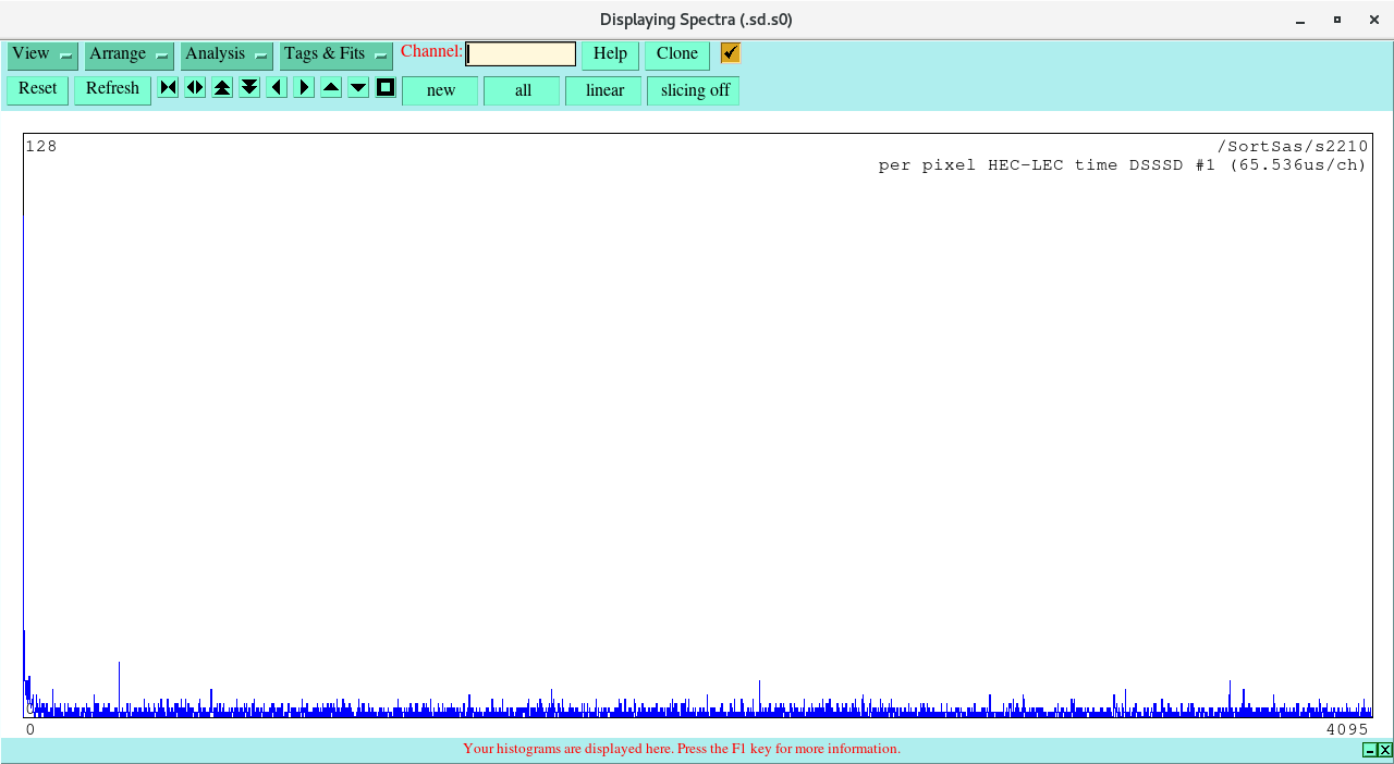
Attachments 3 & 4 - per pixel HEC-LEC event time difference spectra - 65.536us/channel

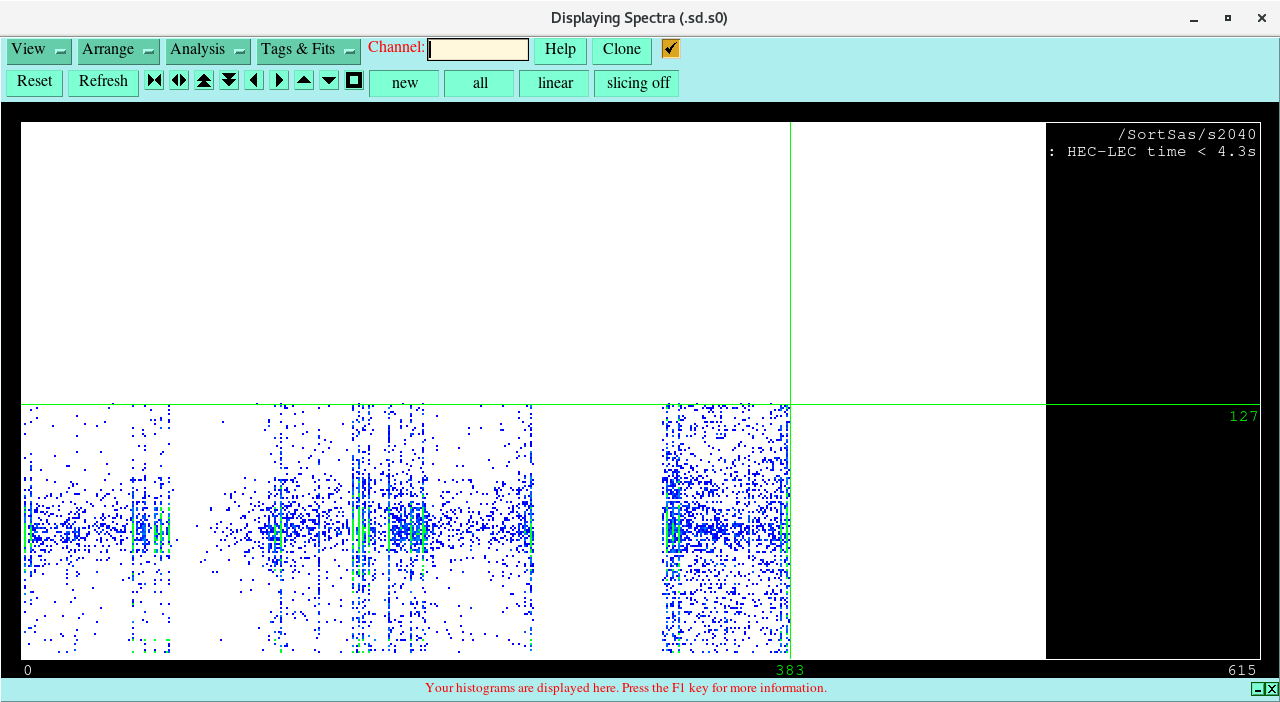
Attachment 5 - DSSSD x-y hit pattern: HEC-LEC event time difference < 4.3s
 Majority of events associated with 'hot' p+n junction strips - few plausible decay candidate events - as expected.
 z-scale - semi-logarithmic - scattered events are single counts ( blue )
 1 count => rate ~ 1/2355s ~ 0.0004Hz, the great majority of pixels have zero counts

Attachment 6 - LEC ( decay ) and HEC ( implant ) events - 262.144us/channel ( 65536 channels = 17.2s )

HEC implants channels 12000-25000 = 216 counts => HEC rate ( in spill ) 63.4Hz
LEC decays channels 12000-25000 = 3865 counts => LEC rate ( in spill ) 1134.1Hz
LEC decays channels 25000-38000 = 2790 counts => LEC rate ( inter spill ) 818.7Hz

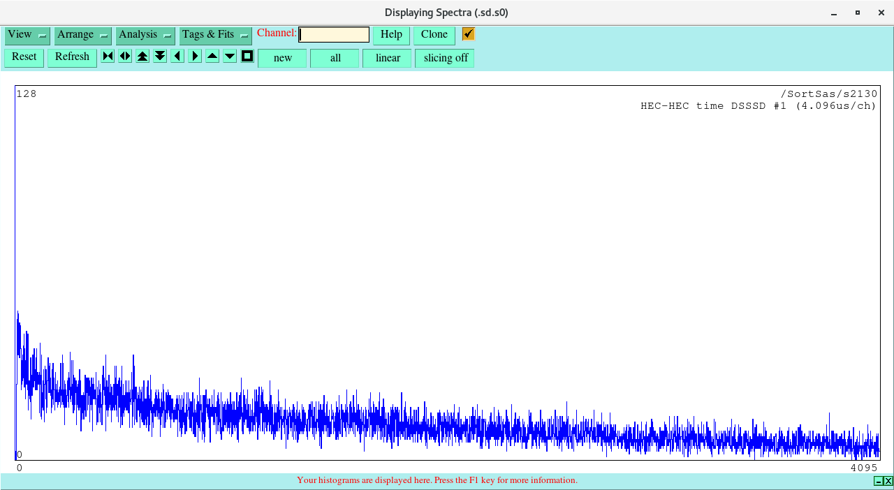
Attachment 7 - per pixel HEC-HEC event time difference spectra - 4.096us/channel

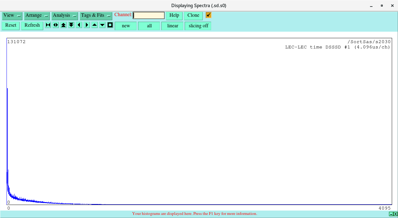
Attachment 8 - per pixel LEC-LEC event time difference spectra - 4.096us/channel

Attachment 9 - variables.dat
This is a ( Fortran ) Namelist I/O data file containing of the ADC offsets, FEE64 configuration, LEC and HEC energy difference windows

The ADC offset channel number is calculated as

channel = channel_ident + ( module * 64 ) where module = 0-7 corresponding to AIDA FEE64s aida01-aida08

and is used as follows

ADC data = INT ( RSHIFT( ABS( 32768 - data( i ) ), 3 ) - offset( i ) + 0.5 )

where data(i) is the ADC data item for channel i, offset(i) is the ADC offset for channel i

An ADC offset of -9999 means there was no pulser data for this channel in data files R5 and R11.
|
| Attachment 1: Screenshot_from_2024-03-01_11-41-11.png
|
|
| Attachment 2: Screenshot_from_2024-03-01_11-41-30.png
|
|
| Attachment 3: Screenshot_from_2024-03-01_11-42-06.png
|
|
| Attachment 4: Screenshot_from_2024-03-01_11-42-22.png
|
|
| Attachment 5: Screenshot_from_2024-03-01_11-43-13.png
|
|
| Attachment 6: Screenshot_from_2024-03-01_11-44-33.png
|

|
| Attachment 7: Screenshot_from_2024-03-01_11-38-52.png
|
|
| Attachment 8: Screenshot_from_2024-03-01_11-40-37.png
|
|
| Attachment 9: variables.dat
|
  $variables
  offset(   0) =    10.71
  offset(   1) =    14.56
  offset(   2) =   -13.88
  offset(   3) =    -9.85
  offset(   4) =   -18.84
  offset(   5) =    -3.41
  offset(   6) =    24.00
  offset(   7) =    23.10
  offset(   8) =    -2.39
  offset(   9) =   -15.90
  offset(  10) =    25.89
  offset(  11) =   -55.27
  offset(  12) =     6.39
  offset(  13) =   -31.83
  offset(  14) =     7.94
  offset(  15) =     7.69
  offset(  16) =     3.46
  offset(  17) =    -3.12
  offset(  18) =    16.24
  offset(  19) =    -6.69
  offset(  20) =    18.42
  offset(  21) = -9999.99
  offset(  22) =   -22.39
  offset(  23) =     1.94
  offset(  24) =   -11.29
  offset(  25) =    -5.55
  offset(  26) =     7.88
  offset(  27) =    -4.32
  offset(  28) =    -7.79
  offset(  29) =   -13.60
  offset(  30) =     2.61
  offset(  31) =    14.95
  offset(  32) =     4.43
  offset(  33) = -9999.99
  offset(  34) =    -6.61
  offset(  35) =   -22.58
  offset(  36) = -9999.99
  offset(  37) =    11.90
  offset(  38) = -9999.99
  offset(  39) =    -1.80
  offset(  40) =   -26.27
  offset(  41) = -9999.99
  offset(  42) =    -1.99
  offset(  43) =    -3.66
  offset(  44) = -9999.99
  offset(  45) =     7.10
  offset(  46) =    -0.31
  offset(  47) =    26.80
  offset(  48) =   -16.60
  offset(  49) = -9999.99
  offset(  50) =    -9.08
  offset(  51) =   -10.53
  offset(  52) =   -28.24
  offset(  53) =    13.09
  offset(  54) =   -12.42
  offset(  55) =   -22.52
  offset(  56) =     3.27
  offset(  57) =   -26.47
  offset(  58) =     7.17
  offset(  59) =     5.31
  offset(  60) =   -29.79
  offset(  61) =    19.75
  offset(  62) =     2.12
  offset(  63) =   -22.37
  offset(  64) =     3.02
  offset(  65) =     1.74
  offset(  66) =    23.39
  offset(  67) =    43.87
  offset(  68) =   -15.18
  offset(  69) =    11.78
  offset(  70) =   -14.59
  offset(  71) =     1.89
  offset(  72) =   -15.75
  offset(  73) =    25.22
  offset(  74) =     7.83
  offset(  75) = -9999.99
  offset(  76) =     6.46
  offset(  77) =    12.32
  offset(  78) =     7.61
  offset(  79) =   -11.58
  offset(  80) =    14.92
  offset(  81) =    -5.12
  offset(  82) = -9999.99
  offset(  83) =    13.14
  offset(  84) =   -13.39
  offset(  85) =    29.08
  offset(  86) =     9.65
  offset(  87) =     5.07
  offset(  88) =   -29.50
  offset(  89) = -9999.99
  offset(  90) =   -32.90
  offset(  91) =    -1.58
  offset(  92) =    10.27
  offset(  93) =    10.60
  offset(  94) =     6.11
  offset(  95) =   -17.37
  offset(  96) = -9999.99
  offset(  97) =   -15.29
  offset(  98) =     5.60
  offset(  99) =    18.18
  offset( 100) =     6.95
  offset( 101) =    34.63
  offset( 102) =    24.44
  offset( 103) = -9999.99
  offset( 104) =    10.31
  offset( 105) =     2.06
  offset( 106) =    24.74
  offset( 107) =    14.27
  offset( 108) =    -2.56
  offset( 109) =    -3.93
  offset( 110) = -9999.99
  offset( 111) =     8.74
  offset( 112) =    10.62
  offset( 113) =     8.13
  offset( 114) =    -9.11
  offset( 115) =    28.90
  offset( 116) =   -22.43
  offset( 117) =    15.39
  offset( 118) =     8.35
  offset( 119) = -9999.99
  offset( 120) =    23.88
  offset( 121) =    -8.30
  offset( 122) = -9999.99
  offset( 123) =   -22.34
  offset( 124) =    -3.13
  offset( 125) = -9999.99
  offset( 126) = -9999.99
  offset( 127) = -9999.99
  offset( 128) =    -5.53
  offset( 129) =    13.01
  offset( 130) =     4.93
  offset( 131) =    -6.37
  offset( 132) =   -14.43
  offset( 133) =    -1.17
  offset( 134) =   -13.50
  offset( 135) =   -29.29
  offset( 136) =     0.38
  offset( 137) =    -2.31
  offset( 138) =    17.01
  offset( 139) =   -28.94
  offset( 140) =    -9.94
  offset( 141) =    10.87
  offset( 142) =    -6.41
  offset( 143) =   -10.41
  offset( 144) =    13.21
  offset( 145) =    10.55
  offset( 146) =   -16.63
  offset( 147) =    -9.88
  offset( 148) =     3.68
  offset( 149) =   -13.44
  offset( 150) =    16.01
  offset( 151) =    -0.66
  offset( 152) =    -4.78
  offset( 153) =     3.88
  offset( 154) =     1.75
  offset( 155) =    14.87
  offset( 156) =    14.93
  offset( 157) = -9999.99
  offset( 158) =    -1.27
  offset( 159) =    11.46
  offset( 160) =     1.60
  offset( 161) =   -17.07
  offset( 162) = -9999.99
  offset( 163) =    -7.67
  offset( 164) =     6.72
  offset( 165) =   -14.06
  offset( 166) =   -13.29
  offset( 167) =    -5.26
  offset( 168) =     9.71
  offset( 169) =   -26.00
  offset( 170) =   -13.22
  offset( 171) =     1.65
  offset( 172) =   -16.16
  offset( 173) =    16.84
  offset( 174) =    10.04
  offset( 175) =   -13.46
  offset( 176) =   -11.55
  offset( 177) =    18.48
  offset( 178) =    26.41
  offset( 179) =    26.68
  offset( 180) =    52.12
  offset( 181) =    -4.79
  offset( 182) =    15.28
  offset( 183) =     7.10
  offset( 184) =    14.26
  offset( 185) =    12.19
  offset( 186) =   -11.96
  offset( 187) =    12.95
  offset( 188) =   -14.44
  offset( 189) =    -0.90
  offset( 190) =     8.53
  offset( 191) =     5.83
  offset( 192) =    14.00
  offset( 193) =    23.65
  offset( 194) =    45.50
  offset( 195) =    19.86
  offset( 196) =    20.01
  offset( 197) =    -5.01
  offset( 198) =    10.92
  offset( 199) =    10.42
  offset( 200) =   -23.83
  offset( 201) =    -8.06
  offset( 202) =    -1.51
  offset( 203) =    11.88
  offset( 204) =   -17.23
  offset( 205) =    22.72
  offset( 206) =   -15.70
  offset( 207) =    69.14
  offset( 208) =   -31.45
  offset( 209) =     4.00
  offset( 210) =     3.27
  offset( 211) =    -1.41
  offset( 212) =    17.72
  offset( 213) =    -9.82
  offset( 214) =    42.36
  offset( 215) =   -14.39
  offset( 216) =   -10.26
  offset( 217) =    16.12
  offset( 218) =   -13.05
  offset( 219) =    32.84
  offset( 220) =     8.33
  offset( 221) =   -31.72
  offset( 222) =    -6.97
  offset( 223) =     9.41
  offset( 224) =    13.02
  offset( 225) =    -4.24
  offset( 226) =     2.84
  offset( 227) =    19.86
  offset( 228) =     1.54
  offset( 229) =    -1.36
  offset( 230) =    -4.71
  offset( 231) =    -8.29
  offset( 232) =    17.26
  offset( 233) =   -27.21
  offset( 234) =     0.91
  offset( 235) =     0.88
  offset( 236) =    25.52
  offset( 237) =    -5.75
  offset( 238) =   -14.34
  offset( 239) =    -1.61
  offset( 240) =     3.03
  offset( 241) =    16.54
  offset( 242) =    -5.54
  offset( 243) =   -18.73
  offset( 244) =     9.95
  offset( 245) =     7.49
  offset( 246) =     6.72
  offset( 247) =   -10.82
  offset( 248) =    22.57
  offset( 249) =    25.84
  offset( 250) =    24.76
  offset( 251) =     9.43
  offset( 252) =    -5.13
  offset( 253) =     6.02
  offset( 254) =     1.75
  offset( 255) =    38.44
  offset( 256) = -9999.99
  offset( 257) =     4.87
  offset( 258) = -9999.99
  offset( 259) =   -22.56
  offset( 260) =     8.35
  offset( 261) =     3.63
  offset( 262) =   -21.39
  offset( 263) =    17.77
  offset( 264) =    -5.50
  offset( 265) =    -3.87
  offset( 266) =     1.14
  offset( 267) =    -1.08
  offset( 268) =     9.44
  offset( 269) =     1.99
  offset( 270) =    -5.29
  offset( 271) =    12.22
  offset( 272) =     4.93
  offset( 273) =    -0.64
  offset( 274) =    22.92
  offset( 275) =   -18.21
  offset( 276) =     0.20
  offset( 277) =    -6.97
  offset( 278) =    14.96
  offset( 279) =    14.56
  offset( 280) =    14.59
  offset( 281) =    -5.61
  offset( 282) =    15.35
  offset( 283) =   -22.48
  offset( 284) =     9.83
  offset( 285) =    19.83
  offset( 286) =   -20.28
  offset( 287) =    27.19
  offset( 288) =    11.79
  offset( 289) =    -8.16
  offset( 290) =    81.33
  offset( 291) =    -4.18
  offset( 292) =   -12.11
  offset( 293) =    -1.70
  offset( 294) =   -12.91
  offset( 295) =     1.57
  offset( 296) =   -12.75
  offset( 297) =   -23.81
  offset( 298) =     4.09
... 227 more lines ...
|
|
|
524
|
Wed Jan 31 15:27:07 2024 |
TD | Photos of water flow & dew point sensor interlock box |
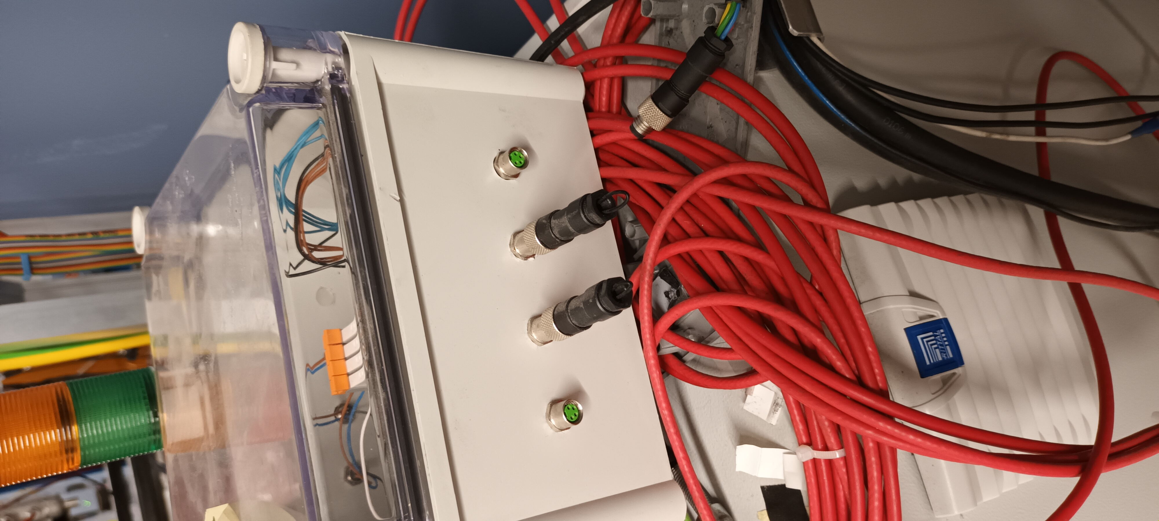
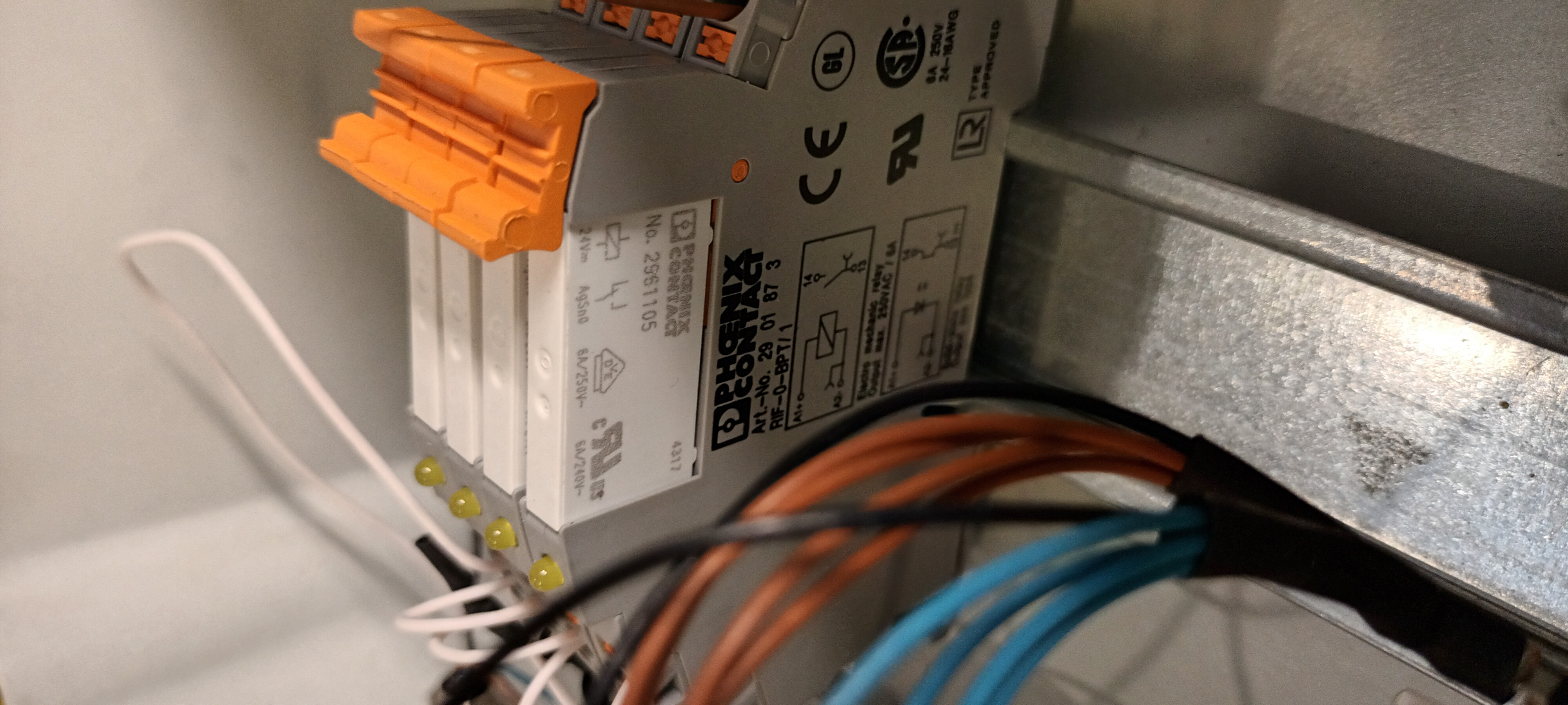
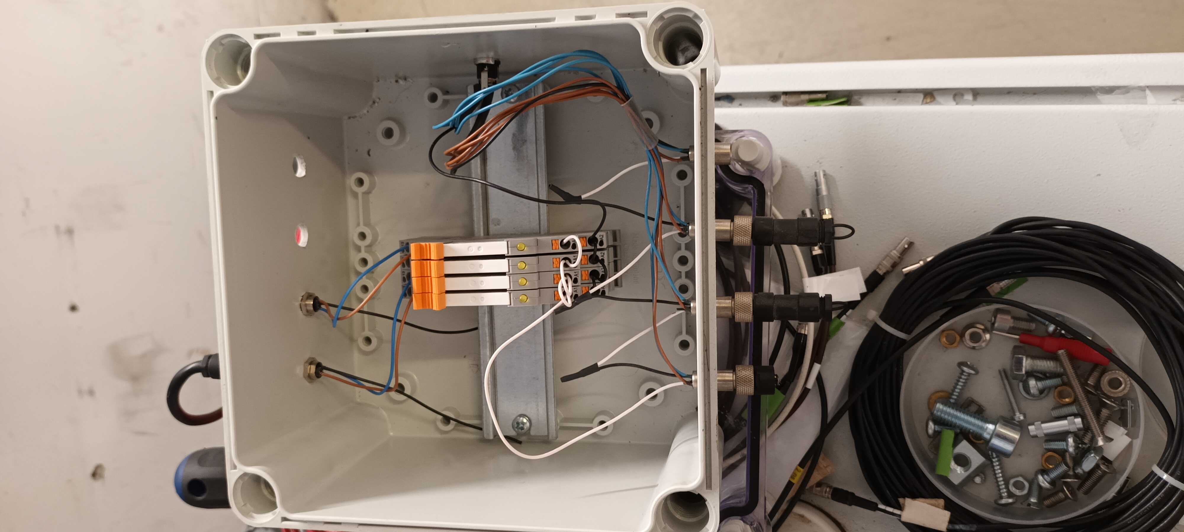
Attachment 1 - 4 socket input connectors ( from sensor to interlock box )

Attachment 2 & 2 - 24V dc relays and internal wiring

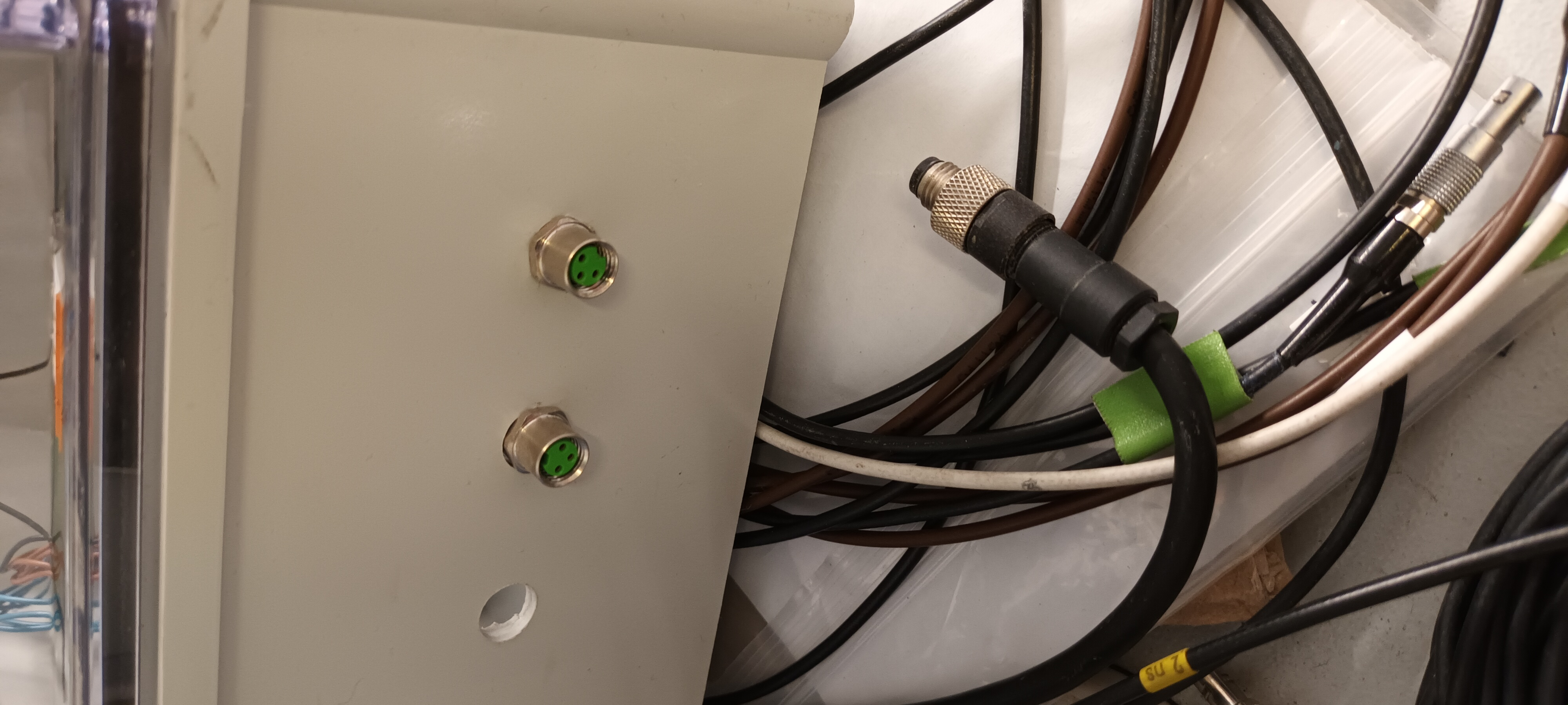
Attachment 4 - 3 socket input connector ( from interlock box to USB-controlled ac mains relay ) |
| Attachment 1: 20240131_160205.jpg
|
|
| Attachment 2: 20240131_145249.jpg
|
|
| Attachment 3: 20240131_145340.jpg
|
|
| Attachment 4: 20240131_160341.jpg
|
|
|
|
523
|
Mon Nov 13 11:46:54 2023 |
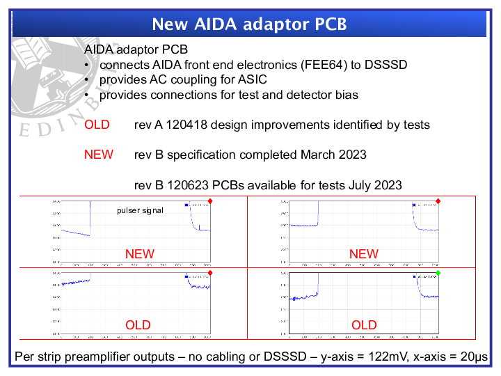
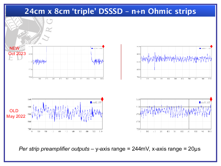
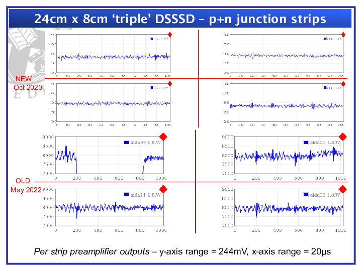
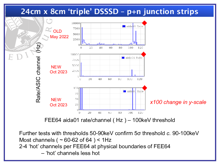
TD | Summary of AIDA 24cm x 8cm 'triple' DSSSD tests |
|
| Attachment 1: Summary_of_AIDA_tests_2022-3_-_Dec_2023.pdf
|



|
| Attachment 2: Summary_of_AIDA_tests_2022-3_-_Dec_2023.pptx
|
|
|
522
|
Thu Oct 12 14:01:43 2023 |
TD | MSL type BB18 24cm x 8cm DSSSD test - update |
DSSSD MSL type BB18 24cm x 8cm 3208-3/3208-21/3208-22

FEE64 configuration see https://elog.ph.ed.ac.uk/AIDA/872 attachment 2

Bias -150V -6.590uA ambient temperature +24.7 deg C d.p. +13.7 deg C RH 50.3%

BNC PB-5
amplitude 10.0V
attenuation x10
decay time 1ms
tail pulse
frequency 25Hz

PB-5 output direct to p+n junction side FEE64 aida01 or aida12, or n+n Ohmic side FEE64 aida02


aida01 1.8.L pulser peak width  61 ch FWHM ~  46keV FWHM => 5s threshold 98keV
aida12 1.8.L pulser peak width  56 ch FWHM ~  42keV FWHM => 5s threshold 89keV
aida02 1.8.L pulser peak width 102 ch FWHM ~  77keV FWHM => 5s threshold 163keV


slow comparator  0xa 100keV ( all p+n junction FEE64s )
                 0xf 150keV ( all n+n Ohmic FEE64s )

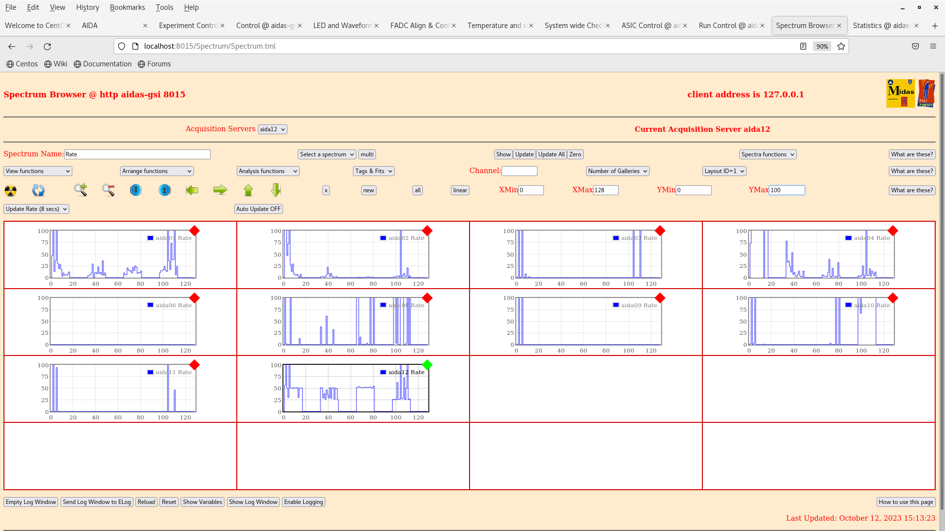
per FEE64 Rate spectra - attachment 1
 p+n FEE64s ( aida010, aida01, aida09, aida12, aida03, aida11 ) rates dominated by hot channels, other channels typically <1Hz ( 25Hz pulser to aida12 )
 n+n FEE64s ( aida02, aida04 ) rates ~ 10-20Hz/channel
 Note aida06 and aida08 are not connected to anything and should be ignored


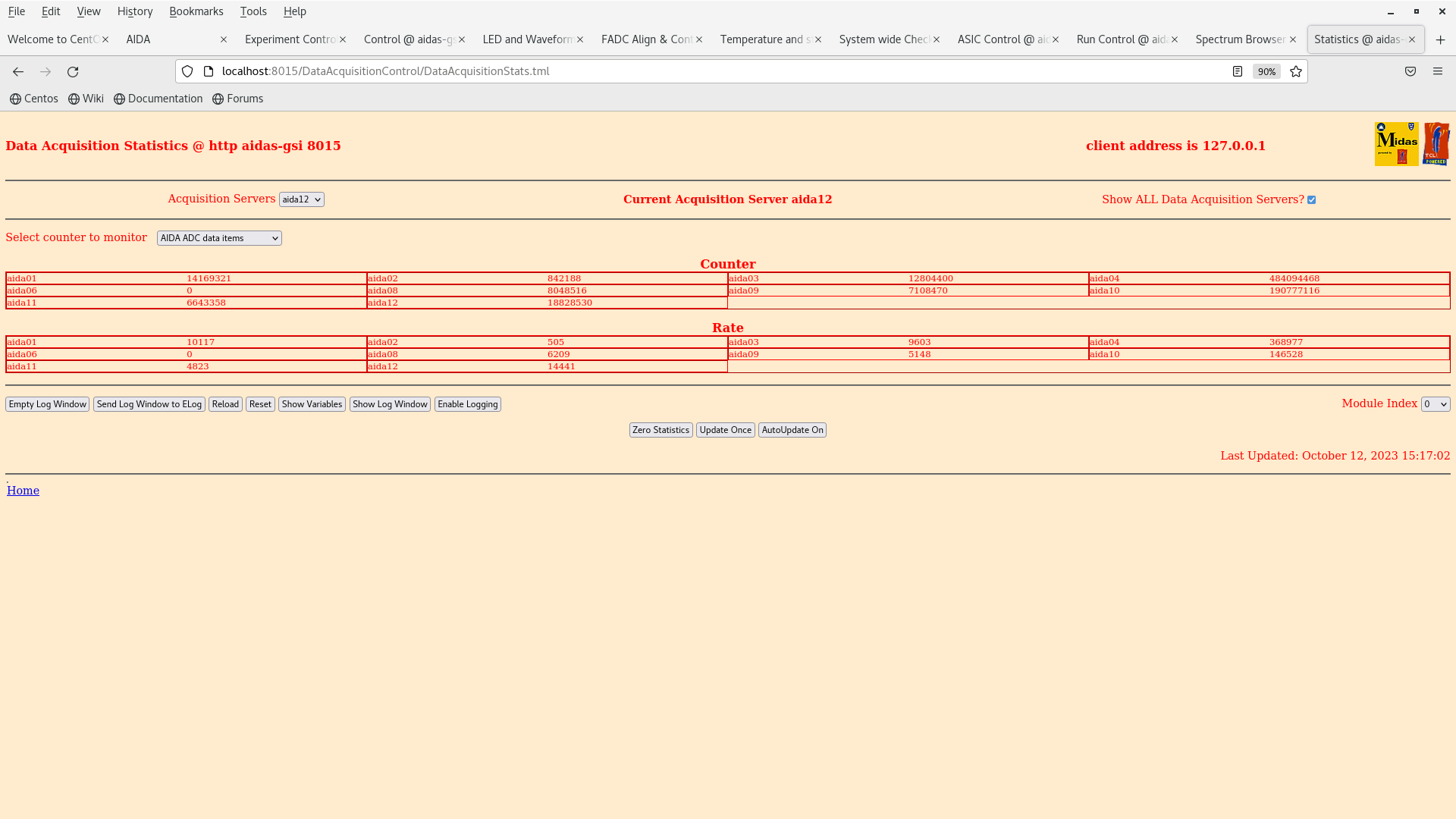
ADC data item stats - attachment 2


For further information see https://elog.ph.ed.ac.uk/AIDA/906 and https://elog.ph.ed.ac.uk/AIDA/907


To Do

- repair/replace Honeywell HSS-DPS dew point sensor
   USB-controlled ac mains relay interlock currently overrriden
   do NOT operate AIDA unattended

- aida04 asic #1 u/s - replace ASIC mezzanine

- electrically isolated test signal distribution box req'd

- aida10 asic #4
   v. high rates observed and large signal transients
   cause unclear ... ASIC/adaptor PCB/cabling/Si wafer ?

- extended background alpha run to check all DSSSD bond wires
   pulser OFF
   slow comparator 0x64

- bPlas + 2x triple DSSSD + bPlas stack assembly and test

- all up, in beam test |
| Attachment 1: Screenshot_from_2023-10-12_15-13-30.png
|
|
| Attachment 2: Screenshot_from_2023-10-12_15-17-05.png
|
|
|
|
521
|
Sun Oct 1 11:47:07 2023 |
TD | S4 cooling water |
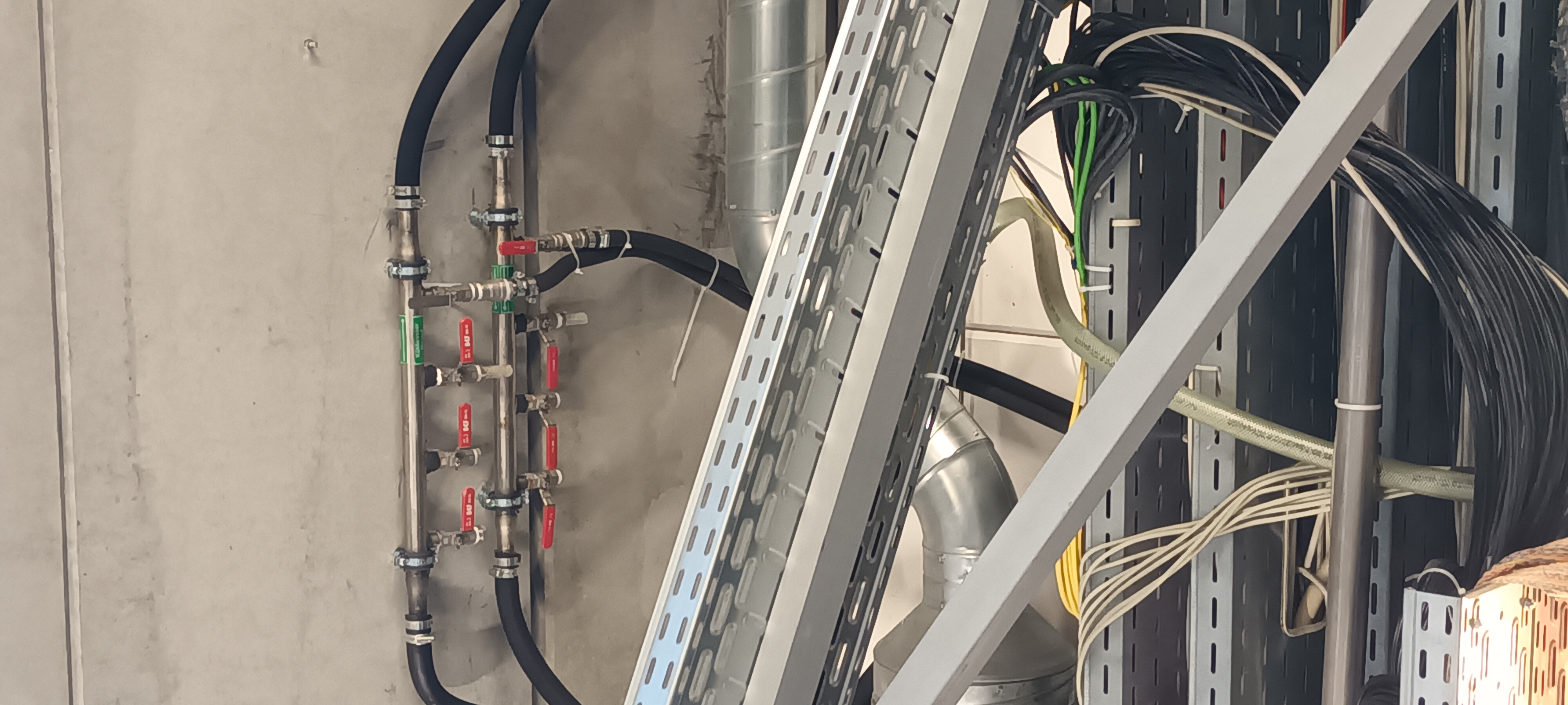
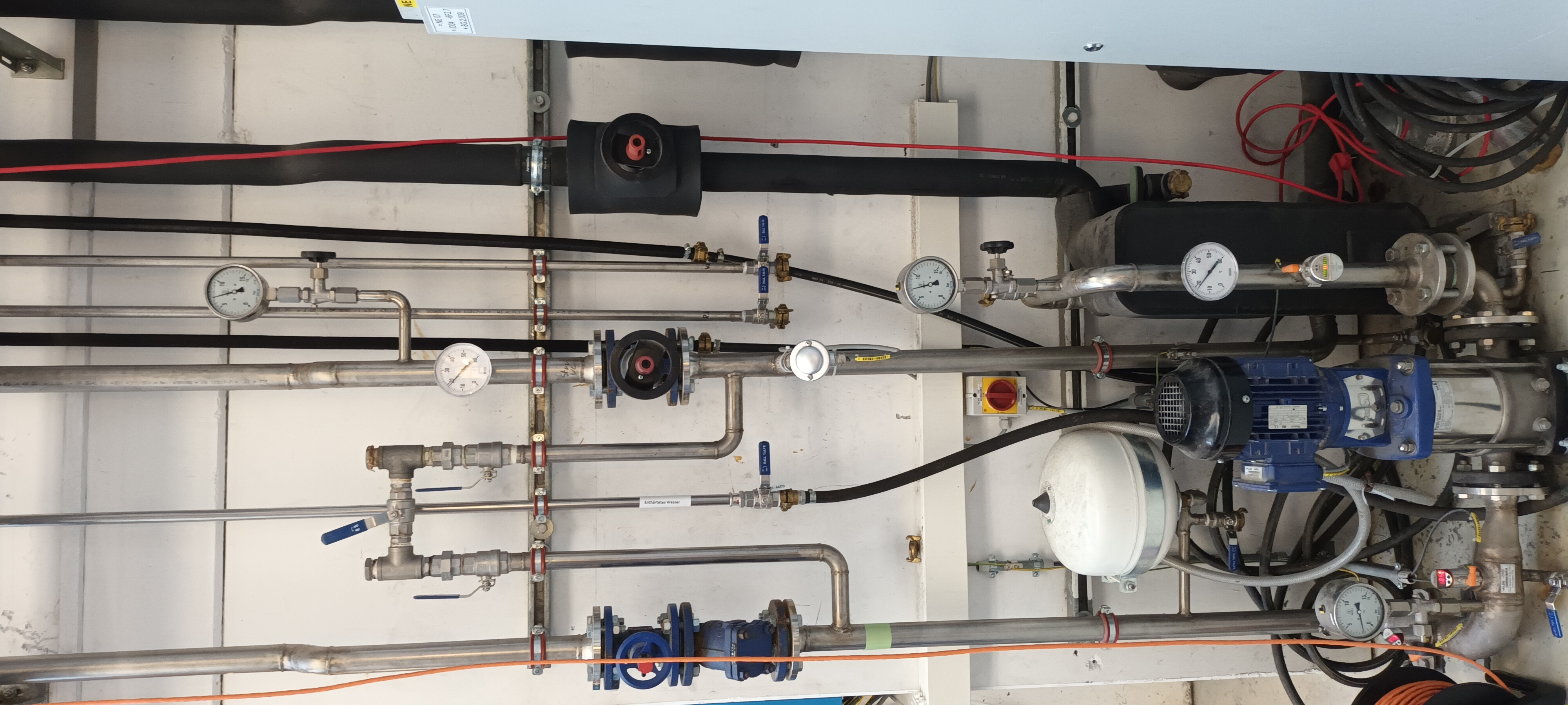
The photographs show the cooling water controls and temperature/pressure gauges outside S4 and the connections used by AIDA within S4. |
| Attachment 1: 1000007356.jpg
|
|
| Attachment 2: 1000007355.jpg
|
|
|
|
520
|
Thu Aug 31 15:24:56 2023 |
NH | New AIDA MBS PC |
The AIDA MBS FDR will be x86l-119 from now on, not x86l-94

the MBS relay and startup scripts will be changed for this |
|
|
519
|
Mon Aug 28 12:47:56 2023 |
NH | Power Failure 24.08.2023 |
There was a power failure in the morning of 24.08.2023 in the Rhein-Main area affecting GSI

The Aida workstation (aida-3) has been restarted, it is unknown if the Pis in S4 rebooted as well (there is a UPS)

29.8.23 TD Both RPi systems rebooted four days ago. |
|
|
518
|
Sun Jul 16 09:32:57 2023 |
TD | Firefox browser proxy setting change |
Firefox browser proxy setting changed to 'Auto-detect proxy settings for this network' ( Firefox -> Edit -> Settings -> Network Settings -> Settings ) |
|
|
517
|
Wed Jan 18 13:40:33 2023 |
PJCS TD | MACB settings with either Emulator or VITAR |
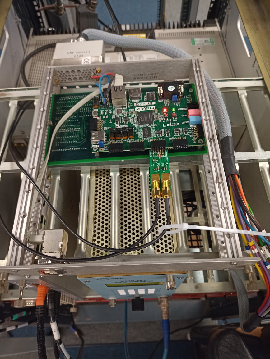
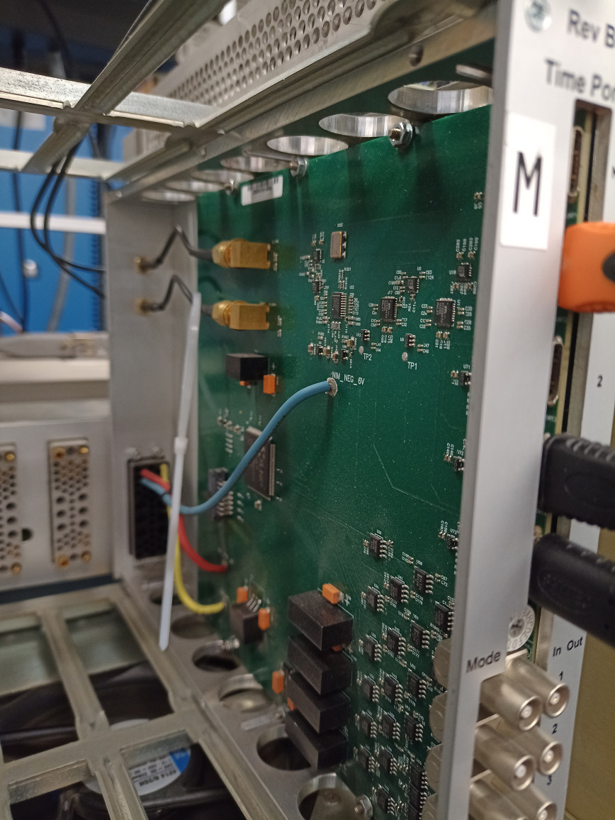
When using the VETAR connected to the HDMI port of the root MACB the settings for all the MACB in the system 0x3.
This setting takes the Clock and Data line from the input HDMI and outputs it via teh HDMI output ports.
When using the Emulator connected via the SMA connectors on the back of the root MACB then the setting for the root MACB should be 0xD and all others should be 0x3.
Attached is the .jed file for programming the MACB and the .vhd source file to help with understanding of the settings. |
| Attachment 1: macb_apr20.jed
|
| Attachment 2: macb_apr20.vhd
|
----------------------------------------------------------------------------------
-- Company:
-- Engineer:
--
-- Create Date:    17:03:27 03/16/2011
-- Design Name:
-- Module Name:    macb_top - Behavioral
-- Project Name:
-- Target Devices:
-- Tool versions:
-- Description:
--
-- Dependencies:
--
-- Revision:
-- Revision 0.01 - File Created
-- Additional Comments:
--
----------------------------------------------------------------------------------
library IEEE;
use IEEE.STD_LOGIC_1164.ALL;
use IEEE.STD_LOGIC_ARITH.ALL;
use IEEE.STD_LOGIC_UNSIGNED.ALL;

---- Uncomment the following library declaration if instantiating
---- any Xilinx primitives in this code.
library UNISIM;
use UNISIM.VComponents.all;
-- NOTE all in/out notations are relative to this unit
entity macb_apr20 is
    Port (
			  port1_sp : inout  STD_LOGIC_VECTOR (3 downto 0);
			  port2_sp : inout  STD_LOGIC_VECTOR (3 downto 0);
			  port3_sp : inout  STD_LOGIC_VECTOR (3 downto 0);
			  port4_sp : inout  STD_LOGIC_VECTOR (3 downto 0);
			  layer_sp : inout  STD_LOGIC_VECTOR (3 downto 0);
			  layer_trigger : out std_logic ;
           sync_return : in  STD_LOGIC_VECTOR (3 downto 1);
           selector : in  STD_LOGIC_VECTOR (3 downto 0);
           sync_select : out  STD_LOGIC_vector(1 downto 0 );
           clock200_select : out  STD_LOGIC_vector( 1 downto 0 ) ;
			  butis_divide_reset : out std_logic ;
			  butis_divide_s : out std_logic_vector( 2 downto 0 ) ;
			  clock_5 : in std_logic ;
			  sync_5 : in std_logic ;
			  trigger : in std_logic_vector( 3 downto 0 ) ;
           MBS_in : in  STD_LOGIC_VECTOR (3 downto 0);
           MBS_out : out  STD_LOGIC_VECTOR (3 downto 0));
end macb_apr20;

architecture Behavioral of macb_apr20 is
signal port1_spi :  STD_LOGIC_VECTOR (3 downto 0) := ( others => '0' );
signal port1_spo :  STD_LOGIC_VECTOR (3 downto 0) := ( others => '0' );
signal port1_t :  STD_LOGIC_VECTOR (3 downto 0) := ( others => '1' );
signal port2_spi :  STD_LOGIC_VECTOR (3 downto 0) := ( others => '0' );
signal port2_spo :  STD_LOGIC_VECTOR (3 downto 0) := ( others => '0' );
signal port2_t :  STD_LOGIC_VECTOR (3 downto 0) := ( others => '1' );
signal port3_spi :  STD_LOGIC_VECTOR (3 downto 0) := ( others => '0' );
signal port3_spo :  STD_LOGIC_VECTOR (3 downto 0) := ( others => '0' );
signal port3_t :  STD_LOGIC_VECTOR (3 downto 0) := ( others => '1' );
signal port4_spi :  STD_LOGIC_VECTOR (3 downto 0) := ( others => '0' );
signal port4_spo :  STD_LOGIC_VECTOR (3 downto 0) := ( others => '0' );
signal port4_t :  STD_LOGIC_VECTOR (3 downto 0) := ( others => '1' );
signal layer_spi :  STD_LOGIC_VECTOR (3 downto 0) := ( others => '0' );
signal layer_spo :  STD_LOGIC_VECTOR (3 downto 0) := ( others => '0' );
signal layer_t :  STD_LOGIC_VECTOR (3 downto 0) := ( others => '1' );
signal seli : integer range 0 to 15 := 0  ;
-- well really
signal MBS_in_n : std_logic_vector( 3 downto 0 ) := "0000" ;
begin
MBS_in_n <= ( not MBS_in);
seli <= conv_integer(not selector) ;
-- MBS signal allocations to sp lines and HDMI pin. This maps to NIM connections
-- 0 :	MBS_clock10 	SP0	13
-- 1 :	MBS_reset		SP1	14
-- 2 :	MBS_reset_rq	SP2	15
-- 3 :	MBS_Trigger		SP3	16
layer_trigger <= trigger(0) or trigger(1) or trigger(2) or trigger(3) ;

-- divider controls set for pass-through
butis_divide_reset <= '1' ; -- for now don't reset ;

process ( seli , MBS_in_n, port1_spi, port2_spi, port3_spi, port4_spi, layer_spi, sync_return ,sync_5  )
-- note : & => concatenate
begin
	case seli is
	when 0 => --- Master/ Root / MBS / Internal clock
		port1_spo <= MBS_in_n(3) & MBS_in_n(2) & '0' & '0' ;
		port1_t <= "0011" ; -- drive trigger and reset request only
		port2_spo <= MBS_in_n(3) & '0' & port1_spi(1) & port1_spi(0) ;
		port2_t <= "0100" ; -- drive clock, reset, trigger only
		port3_spo <= MBS_in_n(3) & '0' & port1_spi(1) & port1_spi(0) ;
		port3_t <= "0100" ; -- drive clock, reset, trigger only
		port4_spo <= MBS_in_n(3) & '0' & port1_spi(1) & port1_spi(0) ;
		port4_t <= "0100" ; -- drive clock, reset, trigger only
		layer_spo <= ( others => '0' ) ;
		layer_t <= ( others => '1' ) ; -- disable the drive to the "next" port
		sync_select <= "00" ; -- select sync from port 1
		clock200_select <= "00" ; -- select internal 200 MHz oscillator
		MBS_out <=  MBS_in_n(3) & MBS_in_n(2) & port1_spi(1) & port1_spi(0) ;
		butis_divide_s <= "000" ; -- s2 is 0 for pass,

	when 1 => --- Master/ Root / MBS / BuTiS clock and SYNC
		port1_spo <= MBS_in_n(3) & MBS_in_n(2) & '0' & '0' ;
		port1_t <= "0011" ; -- drive trigger and reset request only
		port2_spo <= MBS_in_n(3) & '0' & port1_spi(1) & port1_spi(0) ;
		port2_t <= "0100" ; -- drive clock, reset, trigger only
		port3_spo <= MBS_in_n(3) & '0' & port1_spi(1) & port1_spi(0) ;
		port3_t <= "0100" ; -- drive clock, reset, trigger only
		port4_spo <= MBS_in_n(3) & '0' & port1_spi(1) & port1_spi(0) ;
		port4_t <= "0100" ; -- drive clock, reset, trigger only
		layer_spo <= ( others => '0' ) ;
		layer_t <= ( others => '1' ) ; -- disable the drive to the "next" port
		sync_select <= "01" ; -- select sync from external using SMA input
		clock200_select <= "01" ; -- select external 200 MHz oscillator using SMA input
		MBS_out <=  MBS_in_n(3) & MBS_in_n(2) & port1_spi(1) & port1_spi(0) ;
		butis_divide_s <= "000" ; -- s2 is 0 for pass,

	when 2 => --- Master/ Branch / MBS / Next layer clock next layer SYNC
		port1_spo <= layer_spi(3) & layer_spi(2) & '0' & '0' ;
		port1_t <= "0011" ; -- drive trigger and reset request only
		port2_spo <= layer_spi(3) & '0' & port1_spi(1) & port1_spi(0) ;
		port2_t <= "0100" ; -- drive clock, reset, trigger only
		port3_spo <= layer_spi(3) & '0' & port1_spi(1) & port1_spi(0) ;
		port3_t <= "0100" ; -- drive clock, reset, trigger only
		port4_spo <= layer_spi(3) & '0' & port1_spi(1) & port1_spi(0) ;
		port4_t <= "0100" ; -- drive clock, reset, trigger only
		layer_spo <=  '0' & '0' & port1_spi(1) & port1_spi(0) ; -- drive the clock and reset down a layer
		layer_t <= "1100" ; -- just drive the bottom two bits to the "next" port
		sync_select <= "10" ; -- select sync from next_layer
		clock200_select <= "10" ; -- select clock from next layer
		MBS_out <=  layer_spi(3) & layer_spi(2) & port1_spi(1) & port1_spi(0) ;
		butis_divide_s <= "000" ; -- s2 is 0 for pass,

	when 3 => --- Slave / Branch / MBS / Next layer clock and sync
		port1_spo <= layer_spi(3) & '0'  & layer_spi(1) & layer_spi(0);
		port1_t <= "0100" ; -- drive clock, reset, trigger only
		port2_spo <= layer_spi(3) & '0' & layer_spi(1) & layer_spi(0) ;
		port2_t <= "0100" ; -- drive clock, reset, trigger only
		port3_spo <= layer_spi(3) & '0' & layer_spi(1) & layer_spi(0) ;
		port3_t <= "0100" ; -- drive clock, reset, trigger only
		port4_spo <= layer_spi(3) & '0' & layer_spi(1) & layer_spi(0) ;
		port4_t <= "0100" ; -- drive clock, reset, trigger only
		layer_spo <=  '0' & '0' & '0' & '0' ; -- drive nothing
		layer_t <= "1111" ; -- just drive nothing down
		sync_select <= "10" ; -- select sync from next layer
		clock200_select <= "10" ; -- select clock from next layer
		MBS_out <=  layer_spi ; -- map all the signals for monitoring ?
		butis_divide_s <= "000" ; -- s2 is 0 for pass,

	when 4 => --- Master/ Root / MBS / BuTiS clock / Internal SYNC / External timestamp reset
		port1_spo <= MBS_in_n(3) & '0' & MBS_in_n(1)  & '0' ;
		port1_t <= "0100" ; -- drive clock, reset, trigger only
		port2_spo <= MBS_in_n(3) & '0' & MBS_in_n(1)  & '0' ;
		port2_t <= "0100" ; -- drive clock, reset, trigger only
		port3_spo <= MBS_in_n(3) & '0' & MBS_in_n(1)  & '0' ;
		port3_t <= "0100" ; -- drive clock, reset, trigger only
		port4_spo <= MBS_in_n(3) & '0' & MBS_in_n(1)  & '0' ;
		port4_t <= "0100" ; -- drive clock, reset, trigger only
		layer_spo <= ( others => '0' ) ;
		layer_t <= ( others => '1' ) ; -- disable the drive to the "next" port
		sync_select <= "00" ; -- select sync from port 1
		clock200_select <= "01" ; -- select external 50 MHz oscillator using SMA input
		MBS_out <=  MBS_in_n(3) & MBS_in_n(2) & MBS_in_n(1) & sync_5 ;
		butis_divide_s <= "000" ; -- s2 is 0 for pass,

	when 5 => --- Master/ Root / MBS / External 50Mhz clock / Internal Sync
		port1_spo <= MBS_in_n(3) & MBS_in_n(2) & '0' & '0' ;
		port1_t <= "0011" ; -- drive trigger and reset request only
		port2_spo <= MBS_in_n(3) & '0' & port1_spi(1) & port1_spi(0) ;
		port2_t <= "0100" ; -- drive clock, reset, trigger only
		port3_spo <= MBS_in_n(3) & '0' & port1_spi(1) & port1_spi(0) ;
		port3_t <= "0100" ; -- drive clock, reset, trigger only
		port4_spo <= MBS_in_n(3) & '0' & port1_spi(1) & port1_spi(0) ;
		port4_t <= "0100" ; -- drive clock, reset, trigger only
		layer_spo <= ( others => '0' ) ;
		layer_t <= ( others => '1' ) ; -- disable the drive to the "next" port
		sync_select <= "00" ; -- select sync from port 1
		clock200_select <= "01" ; -- select external SMA input
		MBS_out <=  MBS_in_n(3) & MBS_in_n(2) & port1_spi(1) & port1_spi(0) ;
		butis_divide_s <= "000" ; -- s2 is 0 for pass through.

	when 6 => --- Master/ Root / MBS / External 100Mhz clock / Internal Sync
		port1_spo <= MBS_in_n(3) & MBS_in_n(2) & '0' & '0' ;
		port1_t <= "0011" ; -- drive trigger and reset request only
		port2_spo <= MBS_in_n(3) & '0' & port1_spi(1) & port1_spi(0) ;
		port2_t <= "0100" ; -- drive clock, reset, trigger only
		port3_spo <= MBS_in_n(3) & '0' & port1_spi(1) & port1_spi(0) ;
		port3_t <= "0100" ; -- drive clock, reset, trigger only
		port4_spo <= MBS_in_n(3) & '0' & port1_spi(1) & port1_spi(0) ;
		port4_t <= "0100" ; -- drive clock, reset, trigger only
		layer_spo <= ( others => '0' ) ;
		layer_t <= ( others => '1' ) ; -- disable the drive to the "next" port
		sync_select <= "00" ; -- select sync from port 1
		clock200_select <= "01" ; -- select external SMA input
		MBS_out <=  MBS_in_n(3) & MBS_in_n(2) & port1_spi(1) & port1_spi(0) ;
		butis_divide_s <= "100" ; -- s2 is 1 for external, 00 for /2.

	when 7 => --- Fast NIM input for each FEE / Next layer clock next layer SYNC
		port1_spo <= MBS_in_n(0) & layer_spi(2) & '0' & '0' ;
		port1_t <= "0011" ; -- drive trigger and reset request only
		port2_spo <= MBS_in_n(1) & '0' & port1_spi(1) & port1_spi(0) ;
		port2_t <= "0100" ; -- drive clock, reset, trigger only
		port3_spo <= MBS_in_n(2) & '0' & port1_spi(1) & port1_spi(0) ;
		port3_t <= "0100" ; -- drive clock, reset, trigger only
		port4_spo <= MBS_in_n(3) & '0' & port1_spi(1) & port1_spi(0) ;
		port4_t <= "0100" ; -- drive clock, reset, trigger only
		layer_spo <=  '0' & '0' & port1_spi(1) & port1_spi(0) ; -- drive the clock and reset down a layer
		layer_t <= "1100" ; -- just drive the bottom two bits to the "next" port
		sync_select <= "10" ; -- select sync from next_layer
		clock200_select <= "10" ; -- select clock from next layer
		MBS_out <=  layer_spi(3) & layer_spi(2) & port1_spi(1) & port1_spi(0) ;
		butis_divide_s <= "000" ; -- s2 is 0 for pass,

	when 8 => --- Fast NIM input from Input 3 for each FEE / Next layer clock next layer SYNC
		port1_spo <= MBS_in_n(3) & layer_spi(2) & '0' & '0' ;
		port1_t <= "0011" ; -- drive trigger and reset request only
		port2_spo <= MBS_in_n(3) & '0' & port1_spi(1) & port1_spi(0) ;
		port2_t <= "0100" ; -- drive clock, reset, trigger only
		port3_spo <= MBS_in_n(3) & '0' & port1_spi(1) & port1_spi(0) ;
		port3_t <= "0100" ; -- drive clock, reset, trigger only
		port4_spo <= MBS_in_n(3) & '0' & port1_spi(1) & port1_spi(0) ;
		port4_t <= "0100" ; -- drive clock, reset, trigger only
		layer_spo <=  '0' & '0' & port1_spi(1) & port1_spi(0) ; -- drive the clock and reset down a layer
		layer_t <= "1100" ; -- just drive the bottom two bits to the "next" port
		sync_select <= "10" ; -- select sync from next_layer
		clock200_select <= "10" ; -- select clock from next layer
		MBS_out <=  layer_spi(3) & layer_spi(2) & port1_spi(1) & port1_spi(0) ;
		butis_divide_s <= "000" ; -- s2 is 0 for pass,

	when 9 => --- Master/ Root / Internal clock / sync_returns to NIM
		port1_spo <= MBS_in_n(3) & MBS_in_n(2) & '0' & '0' ;
		port1_t <= "0011" ; -- drive trigger and reset request only
		port2_spo <= MBS_in_n(3) & '0' & port1_spi(1) & port1_spi(0) ;
		port2_t <= "0100" ; -- drive clock, reset, trigger only
		port3_spo <= MBS_in_n(3) & '0' & port1_spi(1) & port1_spi(0) ;
		port3_t <= "0100" ; -- drive clock, reset, trigger only
		port4_spo <= MBS_in_n(3) & '0' & port1_spi(1) & port1_spi(0) ;
		port4_t <= "0100" ; -- drive clock, reset, trigger only
		layer_spo <= ( others => '0' ) ;
		layer_t <= ( others => '1' ) ; -- disable the drive to the "next" port
		sync_select <= "00" ; -- select sync from port 1
		clock200_select <= "00" ; -- select internal 200 MHz oscillator
		MBS_out <=  sync_return(3) & sync_return(2) & sync_return(1) & '0' ;
		butis_divide_s <= "000" ; -- s2 is 0 for pass,

	when 10 => --- Master/ Root / MBS / BuTiS clock /2 and SYNC
		port1_spo <= MBS_in_n(3) & MBS_in_n(2) & '0' & '0' ;
		port1_t <= "0011" ; -- drive trigger and reset request only
		port2_spo <= MBS_in_n(3) & '0' & port1_spi(1) & port1_spi(0) ;
		port2_t <= "0100" ; -- drive clock, reset, trigger only
		port3_spo <= MBS_in_n(3) & '0' & port1_spi(1) & port1_spi(0) ;
		port3_t <= "0100" ; -- drive clock, reset, trigger only
		port4_spo <= MBS_in_n(3) & '0' & port1_spi(1) & port1_spi(0) ;
		port4_t <= "0100" ; -- drive clock, reset, trigger only
		layer_spo <= "0000" ;
		layer_t <= ( others => '1' ) ; -- disable the drive to the "next" port
		sync_select <= "01" ; -- select sync from external using SMA input
		clock200_select <= "01" ; -- select external 200 MHz oscillator using SMA input
		MBS_out <=  MBS_in_n ; -- for testing NIM I/O
		butis_divide_s <= "100" ; --  s2 = 1 and s1,s0 decode to 00=>/2 , 01=>/4, /8 , /16

	when 12 => --- Master/ Root / MBS / BuTiS clock /2 and SYNC
		port1_spo <= MBS_in_n(3) & MBS_in_n(2) & '0' & '0' ;
		port1_t <= "0011" ; -- drive trigger and reset request only
		port2_spo <= MBS_in_n(3) & '0' & port1_spi(1) & port1_spi(0) ;
		port2_t <= "0100" ; -- drive clock, reset, trigger only
		port3_spo <= MBS_in_n(3) & '0' & port1_spi(1) & port1_spi(0) ;
		port3_t <= "0100" ; -- drive clock, reset, trigger only
		port4_spo <= MBS_in_n(3) & '0' & port1_spi(1) & port1_spi(0) ;
		port4_t <= "0100" ; -- drive clock, reset, trigger only
		layer_spo <= ( others => '0' ) ;
		layer_t <= ( others => '1' ) ; -- disable the drive to the "next" port
		sync_select <= "01" ; -- select sync from external using SMA input
		clock200_select <= "01" ; -- select external 200 MHz oscillator using SMA input
		MBS_out <=  MBS_in_n(3) & MBS_in_n(2) & port1_spi(1) & port1_spi(0) ;
		butis_divide_s <= "100" ; --  s2 = 1 and s1,s0 decode to 00=>/2 , 01=>/4, /8 , /16

	when 13 => --- Master/ Root / MBS / BuTiS clock /4 and SYNC
		port1_spo <= MBS_in_n(3) & MBS_in_n(2) & '0' & '0' ;
		port1_t <= "0011" ; -- drive trigger and reset request only
		port2_spo <= MBS_in_n(3) & '0' & port1_spi(1) & port1_spi(0) ;
		port2_t <= "0100" ; -- drive clock, reset, trigger only
		port3_spo <= MBS_in_n(3) & '0' & port1_spi(1) & port1_spi(0) ;
		port3_t <= "0100" ; -- drive clock, reset, trigger only
		port4_spo <= MBS_in_n(3) & '0' & port1_spi(1) & port1_spi(0) ;
		port4_t <= "0100" ; -- drive clock, reset, trigger only
		layer_spo <= ( others => '0' ) ;
		layer_t <= ( others => '1' ) ; -- disable the drive to the "next" port
		sync_select <= "01" ; -- select sync from external using SMA input
		clock200_select <= "01" ; -- select external 200 MHz oscillator using SMA input
		MBS_out <=  MBS_in_n(3) & MBS_in_n(2) & port1_spi(1) & port1_spi(0) ;
		butis_divide_s <= "101" ; --  s2 = 1 and s1,s0 decode to  01=>/4

	when 14 => --- Master/ Root / MBS / BuTiS clock /8 and SYNC
		port1_spo <= MBS_in_n(3) & MBS_in_n(2) & '0' & '0' ;
		port1_t <= "0011" ; -- drive trigger and reset request only
		port2_spo <= MBS_in_n(3) & '0' & port1_spi(1) & port1_spi(0) ;
		port2_t <= "0100" ; -- drive clock, reset, trigger only
		port3_spo <= MBS_in_n(3) & '0' & port1_spi(1) & port1_spi(0) ;
... 161 more lines ...
|
| Attachment 3: zybo.jpg
|
|
| Attachment 4: MACB.jpg
|
|
|
|
516
|
Fri Dec 16 14:02:12 2022 |
NH | AIDA System off for christmas break |
The AIDA NIM crate, pis and workstation have been powered off for the Christmas break and will not be accessible |
|
|
515
|
Thu Oct 6 16:51:49 2022 |
NH | Oscilloscope analysis |
Investigating AIDA noise with a TA041 differential probe and oscilloscope

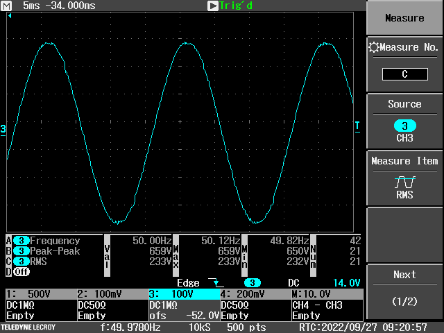
AC Mains (DESPEC platform AC, L-N)
Probe attentuation = 1:100

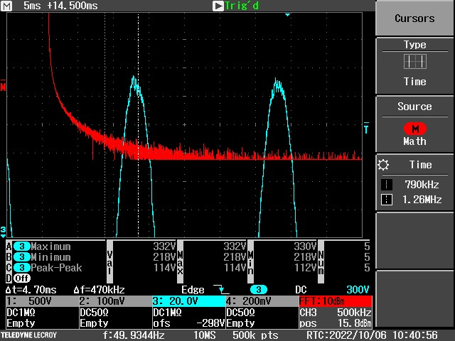
Fig 1: Main AC waveform [X: 5ms/div, Y: 100 V/div]
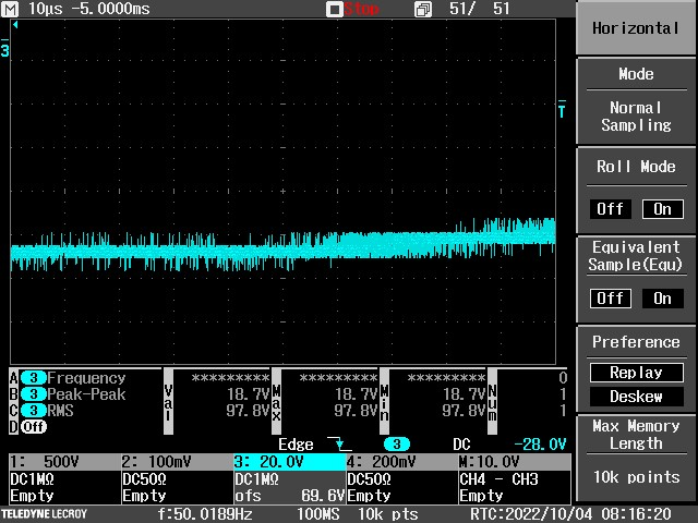
Fig 2: Zoomed in at peak (20 V FSR, any less and the waveform clipped) [X: 10us/div, Y: 20V/div]
Fig 3: Longer time base and FFT of 0-5 MHz. No significant frequency harmonics noticed [X: 5ms/div, Y:20 V, FFT X: 500 kHz/div, Y: 10 dBm/div]

No significant noise or distortion present, fully within any AC specification.
Note that at the moment there is almost no load on AC
Equipment on on DESPEC rack: AIDA NIM, AIDA Raspberry Pis, bPlas PC (+ WR) + 2x DESPEC NIM crates
 No autofill, VME crate or detectors
All big machines at GSI (SIS, FRS) off (suspect pumps are on)

Ion catcher not on (I think under repair)

-

FEE PSU studies
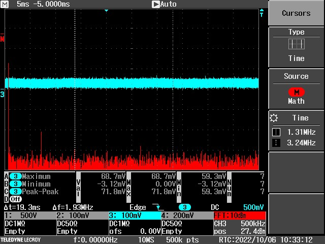
Probe connected to 5V exposed power pin on FEE64 (+v) and to grounding crimp on FEE64 (-v)
No adapter board connected
Attentuation = 1:10


Fig 4: FFT when FEEs are *off* - essentially probe+scope noise [X: 5ms/div, Y: 100 mV/div, FFT: X: 500 kHz/div, Y: 10 dBm/div]
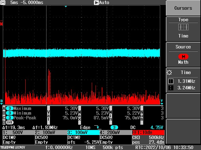
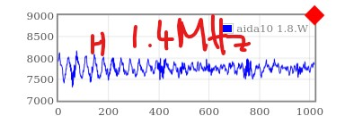
Fig 5: FFT when FEEs are *on* - notice 1.4 MHz peak in FFT, also seen on ADC waveform readout before (fig 6) [X: 5ms/div, Y: 100 mV/div, FFT: X: 500 kHz/div, Y: 10 dBm/div]

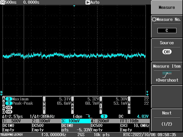
Fig 7: 500 ns/div 5V output on FEE, single FEE on the PSU [X: 500 ns/div, Y: 100 mV/div]

Note average max voltage is 5.31 V (power on) and ~ 70 mV "peak to peak" -might be from probe/scope?

Also see voltage changes with FEE power draw:

Power on  : 5.45 V (different scale to above)
SETUP ran : 5.51 V
FADCs off : 5.86 V
ACQ Go:   : Unchanged; ASIC threshold 0xa: Unchanged

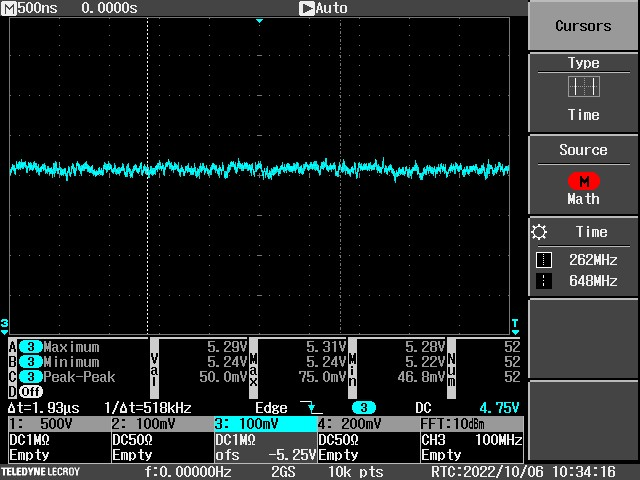
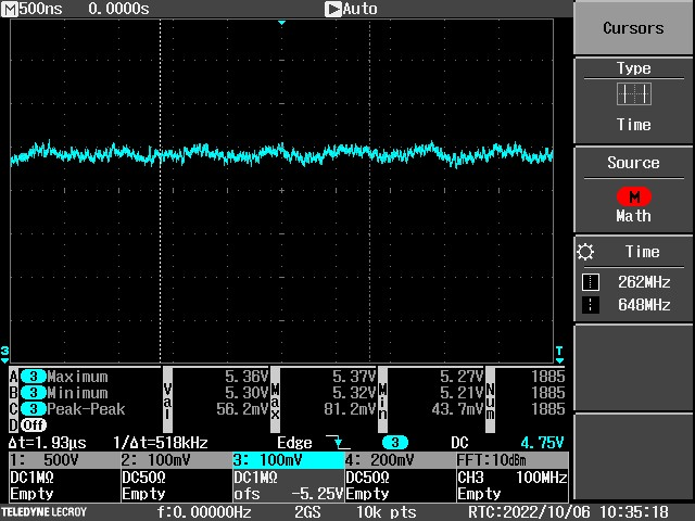
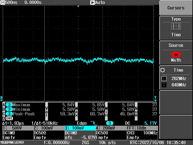
Also check situation on a fully loaded PSU (8 fees connected and powered on)

Power on:   5.29 V (fig 8)
SETUP ran:  5.36 V (fig 9)
FADCs off:  5.64 V (fig 10)

All X: 500 ns/div, Y: 100 mV/div

Both cases observe voltage rises as current draw drops (as expected for voltage drop along a cable)

Noise on 'scope seems to get slightly worse with reduced current (and higher voltage)

No sign of strong 100 kHz noise as seen in ADC traces beforehand

Todo:

- Check -6V and 7V rails
- Check 5V and noise when front-end card is added and pulser/HV connected
- Check between two FEE64 grounds
- Check direct out of PSU vs ground to see if 1.4 MHz appears on PSU side or FEE64 side

-
11.10.22 Updates

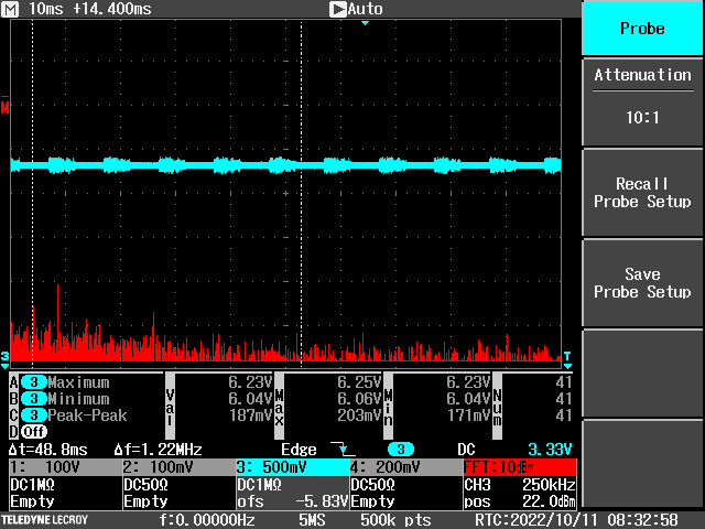
Attachement 11 - 5V PSU on upper PSU with no FEEs attached whatsoever. No 1.4 MHz (on FFT) but clear low frequency beats from switching - presumably low/no load behaviour

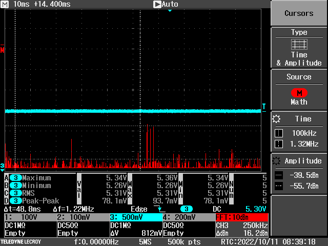
Attachement 12 - 5V PSU on aida12 with 8 FEEs on PSU. Longer time base to allow lower frequencies in FFT. 1.4 MHz switching spikes visible but nothing around 100 kHz region

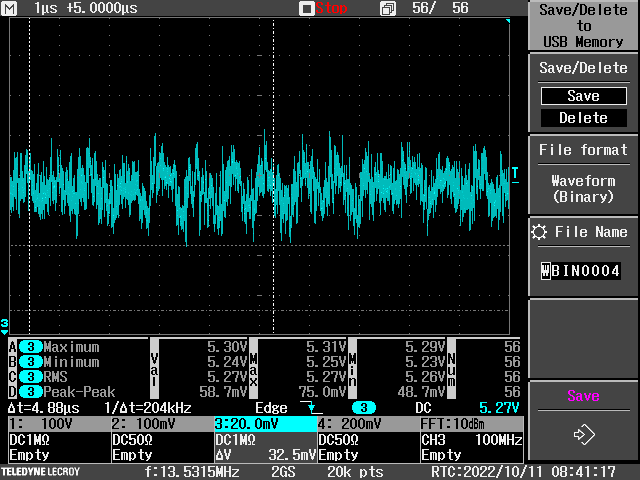
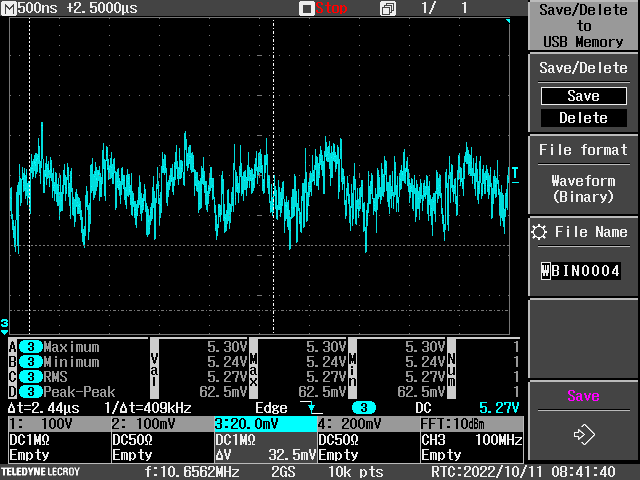
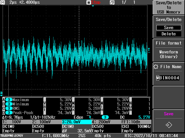
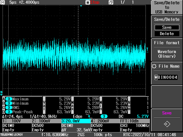
Attachments 13-16: 5V PSU on aida12 at 20 mV/div vertical and 1, 0.5, 2, 5 us/div horizontal respectively

12.10.22 Updates

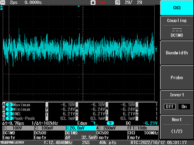
Attachment 17: -6V PSU on aida12 with 8 FEEs on PSU. 2 us/div timebase. 20 mV/div amplitude
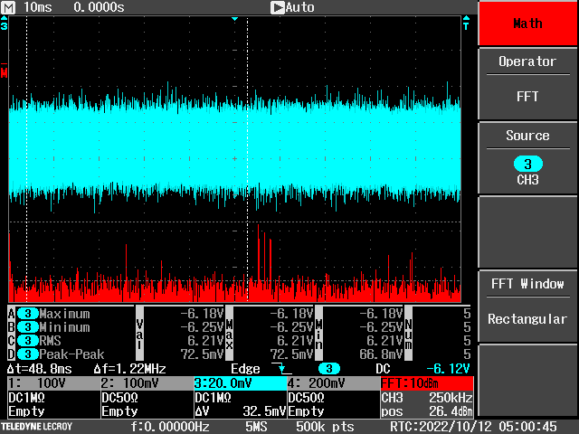
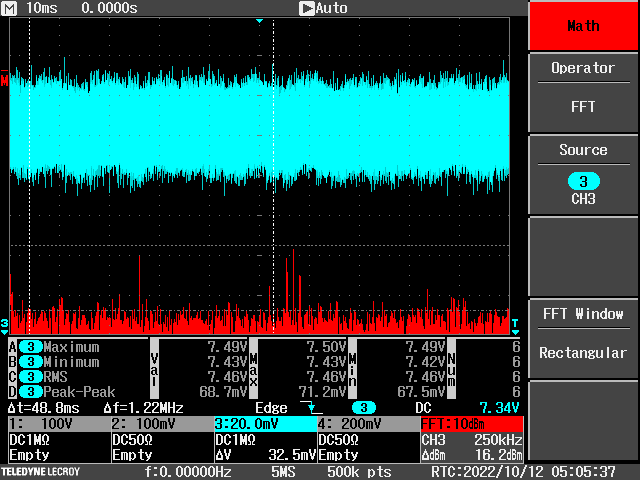
Attachment 18: 10 ms timebase and FFT
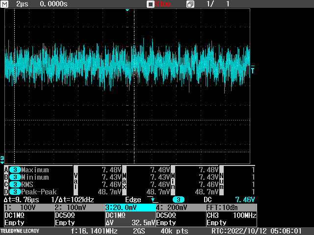
Average voltage: -6.21 V

Attachment 19: 7V PSU on aida12 with 8 FEEs on PSU. 2 us/div timebase. 20 mV/div amplitude
Attachment 18: 10 ms timebase and FFT
Average voltage: 7.46V

Measurement between AIDA12 ground and Reference ground/copper bar
+ve (red probe) attached to copper bar at ground point (not strong connection at present)
-ve (black probe) attached to ground crimp on aida12 (connected to cooling plate)
aida12 no adapter board connected: connections are PSU, Ethernet, HDMI and TTY only

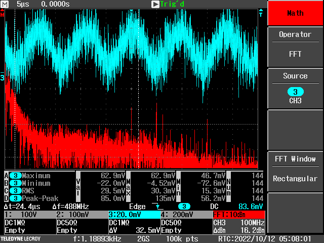
Attachment 21: 5 us/div 100 mv/div waveform, big oscillations present. Not seen before FEEs turned on (8 FEES, 1-7+12)
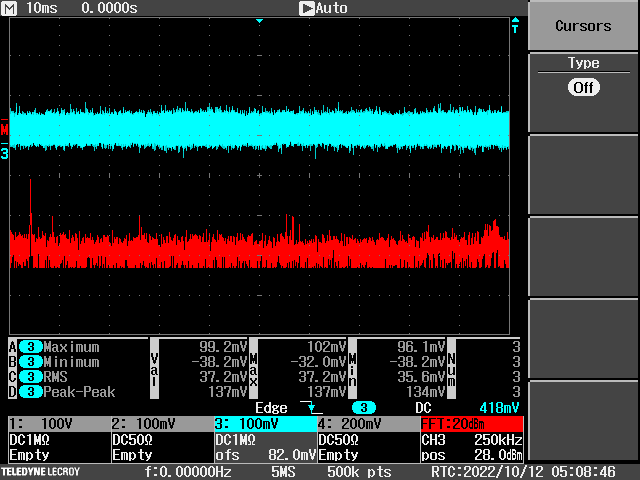
Attachment 22: 10 ms/div for FFT, sharp peak at exactly 100 kHz observed...


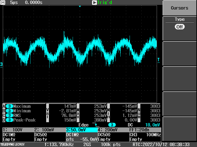
Attachment 23: Between 5V PSU (+ve) and 19" rack (-ve) with  no FEEs connected to PSU
 See strong 100 kHz oscillations too, note that voltage isn't 5V as PSU is floating w.r.t. ground
 Looks to be common mode noise (on both 5V and Return of PSU)

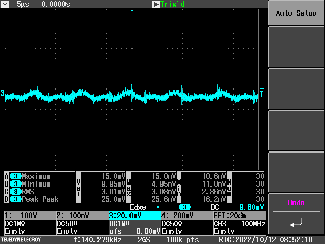
Attachment 24: Same as 21 but using thick crocodile clips on probe to ground and aida12. Noise is attenuated but still present |
| Attachment 1: SCRN0086.PNG
|
|
| Attachment 2: SCRN0090.jpg
|
|
| Attachment 3: SCRN0113.jpg
|
|
| Attachment 4: SCRN0107.jpg
|
|
| Attachment 5: SCRN0108.jpg
|
|
| Attachment 6: Image_Pasted_at_2022-10-6_15-51.jpg
|
|
| Attachment 7: SCRN0098.jpg
|
|
| Attachment 8: SCRN0109.jpg
|
|
| Attachment 9: SCRN0110.jpg
|
|
| Attachment 10: SCRN0111.jpg
|
|
| Attachment 11: SCRN0115.PNG
|
|
| Attachment 12: SCRN0121.PNG
|
|
| Attachment 13: SCRN0124.PNG
|
|
| Attachment 14: SCRN0125.PNG
|
|
| Attachment 15: SCRN0126.PNG
|
|
| Attachment 16: SCRN0127.PNG
|
|
| Attachment 17: SCRN0132.PNG
|
|
| Attachment 18: SCRN0129.PNG
|
|
| Attachment 19: SCRN0139.PNG
|
|
| Attachment 20: SCRN0136.PNG
|
|
| Attachment 21: SCRN0141.PNG
|
|
| Attachment 22: SCRN0143.PNG
|
|
| Attachment 23: SCRN0149.PNG
|
|
| Attachment 24: SCRN0153.PNG
|
|
|
|
514
|
Wed Sep 14 19:07:07 2022 |
PJCS | INFO : Three Merger Statistics explained |
There are three Merger statistics that can be used to better understand how the data flow through the Merger system is proceeding.
Two are from the Link task and one is from the Merger.They are all "No data buffers avaliable" with #1, #2, #3 at the end.
#1: This is incremented when the Link task has a data item to put in the queue for the Merge process but there is no room.
#2: This is incremented when the Link task has found no room in the queue for the Merge process ( #1 ) , waited , tried again and failed.
#3: This the other end of the queue. When the Merge task requests a data item from a Link task queue and there is nothing available.
|
|
|
513
|
Thu Sep 8 12:37:18 2022 |
NH | Proxy Port Changed |
The proxy in Firefox, Yum and AnyDesk has been changed as the old wasn't working

proxy.gsi.de port 3128 is now in use |
|
|
512
|
Thu Sep 8 12:31:25 2022 |
NH | Retrying AIDA DataAcq v10 |
Startup AIDA with ribbon cable connected to aida03 and aida07 for noise

Setup and run with waveforms enabled. Discriminators ADC power etc as default

Try to push above 200k as this is where we saw issues before... lowering threshold to 0x3 pushes rates to

aida03 - 320k
aida07 - 254k

Startup merger and observe rates

aida03 - 224k
aida07 - 213k

Rate drop observed as before.

Now update aidacommon to point to AidaExecV10 and powercycle FEEs

Rates again with 0x3

aida03 - 315k
aida07 - 252k

Restart with data transfer ON

aida03 - 317k
aida07 - 262k

No errors in merger terminal or "Merge time errors" statistic

Will keep running |
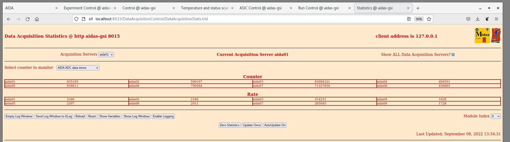
| Attachment 1: AnyDeskMSI_2022-09-08_13-35-50.png
|
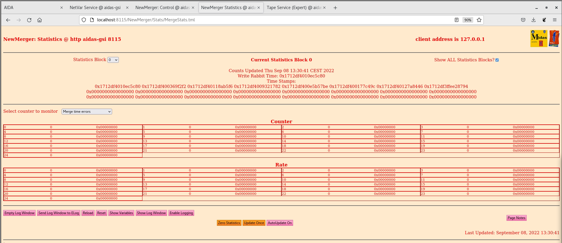
|
| Attachment 2: AnyDeskMSI_2022-09-08_13-35-58.png
|
|
| Attachment 3: AnyDeskMSI_2022-09-08_13-36-02.png
|
|
|
|
511
|
Tue Aug 30 13:48:32 2022 |
NH | AIDA Single Switch Configuration |
The second switch was moved back to CARME so AIDA has been configured back to using a single switch

aida02/aida04/aida06/aida08 updated back to first switch as per https://elog.ph.ed.ac.uk/DESPEC/433

Additionally a ribbon cable is attached to aida01 and aida05 to introduce some noise into the system |
|
|
510
|
Tue Jul 5 08:53:20 2022 |
TD | To Do |
In no particular order

1) CAEN 83xx series NIM bin (Ortec 533A output noise issue)

   observe +/- 6V, 12V, 24V lines with/without load

   try new CAEN NIM bin and/or NIM bin of different type

2) Measure actual voltages at FEE64 power connector input

   OH suggests fab of power adaptor for safe observation - contact EW

3) rev B adaptor PCB

   invert 125 way ERNI - check for mech conflicts
   paired HV input (avoid Lemo-00 T pieces)
   consider isolating test/HV Lemo-00 shells from PCB ground (loop elimination)
   straight jumpers
   shrouded Samtec headers - consider mech issues/consequences of using eject clips too
   re-visit HV filtering & separate trace ground

4) isolation transformer

   as practical matter may be necessary to operate all platform from isolation transformer
   consider hire of appropriate unit

   need method to measure isolation - will require permit to work or equiv

5) investigate S4 area ac mains

   NH discussing with GSI electricians

6) Systematic measurement of AIDA PSU noise

   Spec linear AIDA FEE64 PSU

7) Redesign of snout
   Return to 1mm welded box Al for lower stage of snout  for added rigidity

8) Revisit calculation of cable lengths. Particularly for the triple

9)
|
|
|
509
|
Wed Jun 29 10:48:26 2022 |
NH, OH | AIDA Dismounted |
All detectors removed from single and triple AIDA snouts

Empty snouts *and* DSSDs (in boxes) stored in NH office |
|
|
508
|
Tue Jun 28 10:11:35 2022 |
OH, NH | MIDAS Data Aq V10 |
11:11 Rebooted FEEs and changed aidacommon in /MIDAS/linux-ppc_4xx/startup to point to the new V10 DataAq that Patrick produced
      When using V9 the Merger statistics reported WR items at twice the rate of ADC data items.
      i.e for ever data item we were sending and info code 4 and info code 5 item sending 192 bits of data vs 64 for just the data word
      This was causing significant deadtime when FEEs were running in the range of around 200kHz. These WR items were not reported by the MIDAS Acquisition server but were in the Merger statistics

      Patrick has produced V10 which removes these.

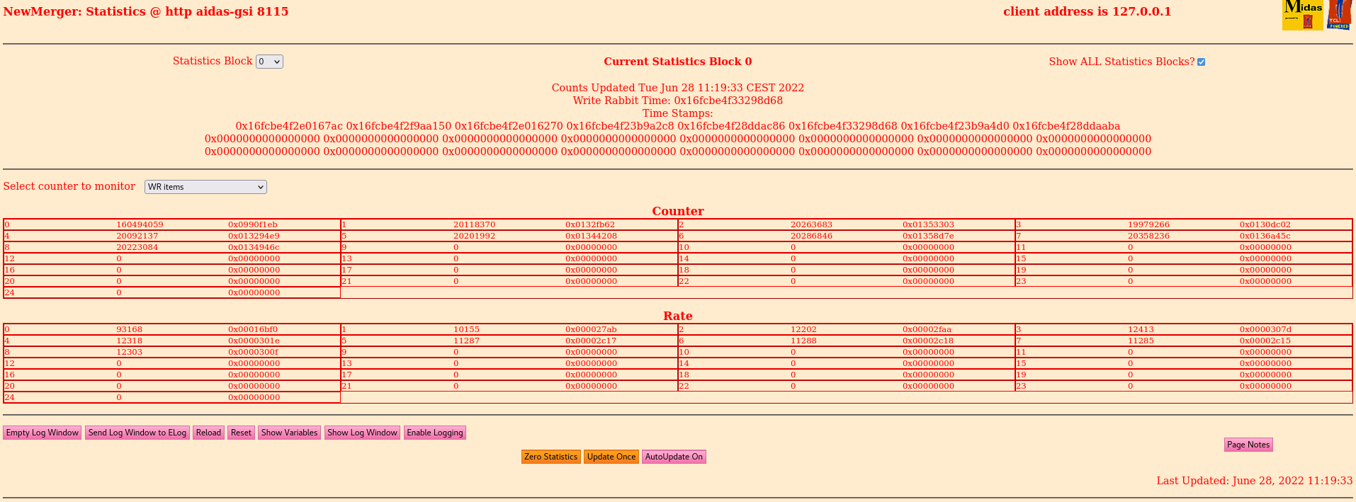
      When running V10 we can confirm in the Merger statistics that this rate is no longer determined by the ADC data rate and instead controlled via Sync Rollover Target in GSI WhiteRabbit Control.
      WR items for 0xE - attachment 1
      WR items for 0x7 - attachment 2

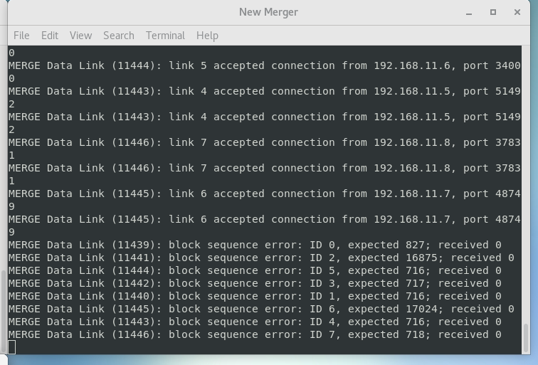
      However we see in the NewMerger terminal the message shown in attachment 3 frequently.
      Also we note that the merger time error counter is also going up.
      Our thoughts for this are we have a rollover issue (Is the merger expecting the rollover of the LSB to be one value when the MSB is updated but MIDAS is happening on another?)
      Are we having dead time issues which is causing time warps?

      Does each buffer from the MIDAS Data Acq start with a full WR timestamp?

aidacommon has been changed back to point to V9 to not cause issues when we run the DAQ and forget we changed it to be this way? |
| Attachment 1: 220628_1117_Rollover0xE.png
|

|
| Attachment 2: 220628_1119_Merger_Stats_0x7.png
|
|
| Attachment 3: NewMerger_Dump.txt
|
MERGE Data Link (17671): block sequence error: ID 2, expected 462; received 0
MERGE Data Link (17669): block sequence error: ID 0, expected 461; received 0
MERGE Data Link (17672): block sequence error: ID 3, expected 462; received 0
MERGE Data Link (17670): block sequence error: ID 1, expected 462; received 0
MERGE Data Link (17674): block sequence error: ID 5, expected 463; received 0
MERGE Data Link (17676): block sequence error: ID 7, expected 462; received 0
MERGE Data Link (17675): block sequence error: ID 6, expected 461; received 0
MERGE Data Link (17673): block sequence error: ID 4, expected 462; received 0
MERGE Actor (17699): Working with 0 from 8 data sources

MERGE Actor (17699): Working with 0 from 8 data sources

MERGE Actor (17699): Working with 0 from 8 data sources

MERGE Actor (17699): Working with 0 from 8 data sources

MERGE Actor (17699): Working with 0 from 8 data sources

MERGE Actor (17699): Working with 0 from 8 data sources

MERGE Actor (17699): Working with 0 from 8 data sources

MERGE Actor (17699): Working with 0 from 8 data sources

MERGE Actor (17699): Working with 0 from 8 data sources

MERGE Actor (17699): Working with 0 from 8 data sources

MERGE Actor (17699): Working with 0 from 8 data sources

MERGE Actor (17699): Working with 0 from 8 data sources

MERGE Actor (17699): Working with 0 from 8 data sources

MERGE Actor (17699): Working with 0 from 8 data sources

MERGE Actor (17699): Working with 0 from 8 data sources

MERGE Actor (17699): Working with 0 from 8 data sources

MERGE Actor (17699): Working with 0 from 8 data sources

MERGE Actor (17699): Working with 0 from 8 data sources

MERGE Actor (17699): Working with 0 from 8 data sources

MERGE Actor (17699): Working with 0 from 8 data sources

MERGE Actor (17699): Working with 0 from 8 data sources

MERGE Actor (17699): Working with 0 from 8 data sources

MERGE Actor (17699): Working with 0 from 8 data sources

MERGE Actor (17699): Working with 0 from 8 data sources

MERGE Actor (17699): Working with 0 from 8 data sources

MERGE Actor (17699): Working with 0 from 8 data sources

MERGE Actor (17699): Working with 0 from 8 data sources

MERGE Actor (17699): Working with 0 from 8 data sources

MERGE Actor (17699): Working with 0 from 8 data sources

MERGE Actor (17699): Working with 0 from 8 data sources

MERGE Actor (17699): Working with 0 from 8 data sources

MERGE Actor (17699): Working with 0 from 8 data sources

MERGE Actor (17699): Working with 0 from 8 data sources

MERGE Actor (17699): Working with 0 from 8 data sources

MERGE Actor (17699): Working with 0 from 8 data sources

MERGE Actor (17699): Working with 0 from 8 data sources

MERGE Actor (17699): Working with 0 from 8 data sources

MERGE Actor (17699): Working with 0 from 8 data sources

MERGE Actor (17699): Working with 0 from 8 data sources

MERGE Actor (17699): Working with 0 from 8 data sources

MERGE Actor (17699): Working with 0 from 8 data sources

MERGE Actor (17699): Working with 0 from 8 data sources

MERGE Actor (17699): Working with 0 from 8 data sources

MERGE Actor (17699): Working with 0 from 8 data sources

MERGE Actor (17699): Working with 0 from 8 data sources

MERGE Actor (17699): Working with 0 from 8 data sources
|
|
|
507
|
Tue Jun 28 09:37:19 2022 |
NH | Tues 28 June 08:00- |
Experiment over

10:37 - Stop DAQ & Tape

S4 enters controlled access and they uncable bPlas

Will dismount AIDA snout after |