| ID |
Date |
Author |
Subject |
|
375
|
Tue Aug 17 12:39:25 2021 |
NH, TD | AIDA Noise |
Investigate noise situation of AIDA (no DSSSDs connected)

Figs 1-6: Waves, Pulser Peaks + Widths *before* any changes
- aida16 very noisy ASICS 1&2, normal ASICS 3&4
- back-side aidas (02,04,06,08) worse resolution than front-side
- high-frequency noise still noticeable in waveforms

Figs 7-8: Remove pulser in (from NIM rack) only
- no noticable change

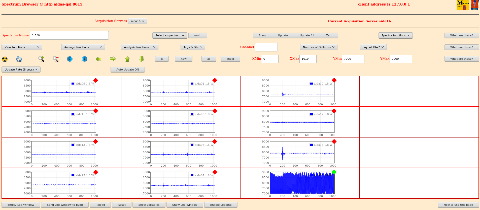
Figs 9-10: Remove all pulser cables from adapter boards
- looks improved

Figs 11-12: HV Braid->GND Jumpers removed

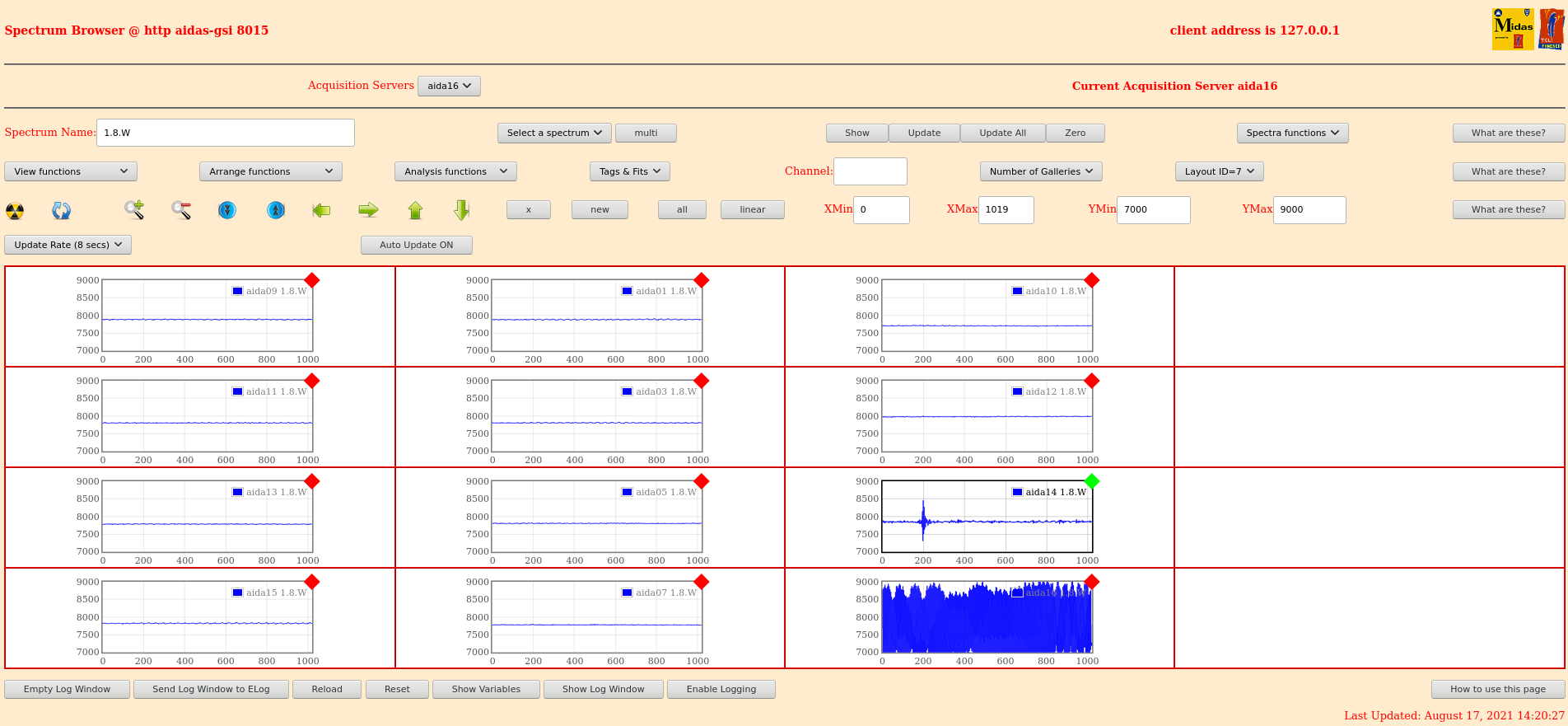
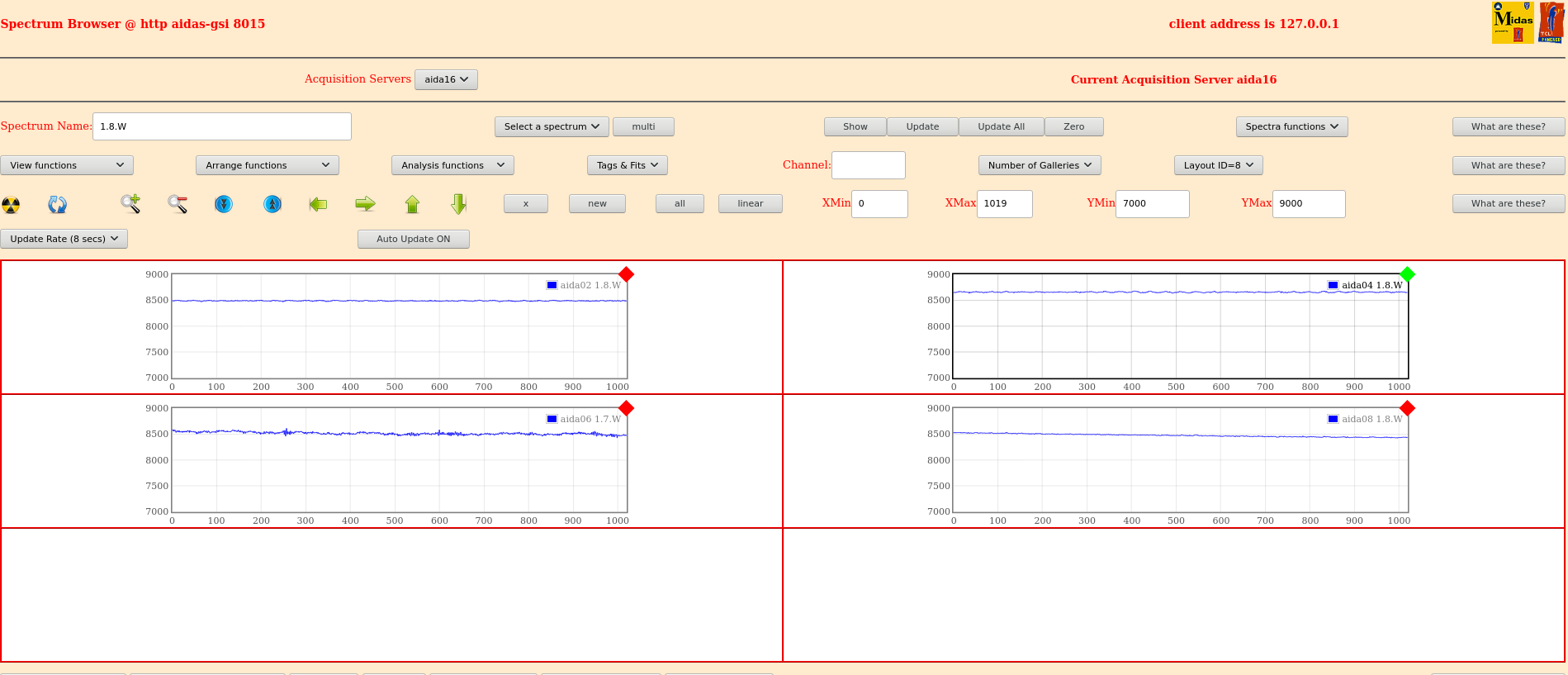
Fig 13-14: All HV cables removed
- aida06, aida14 isn't updating
- very noticable improvement

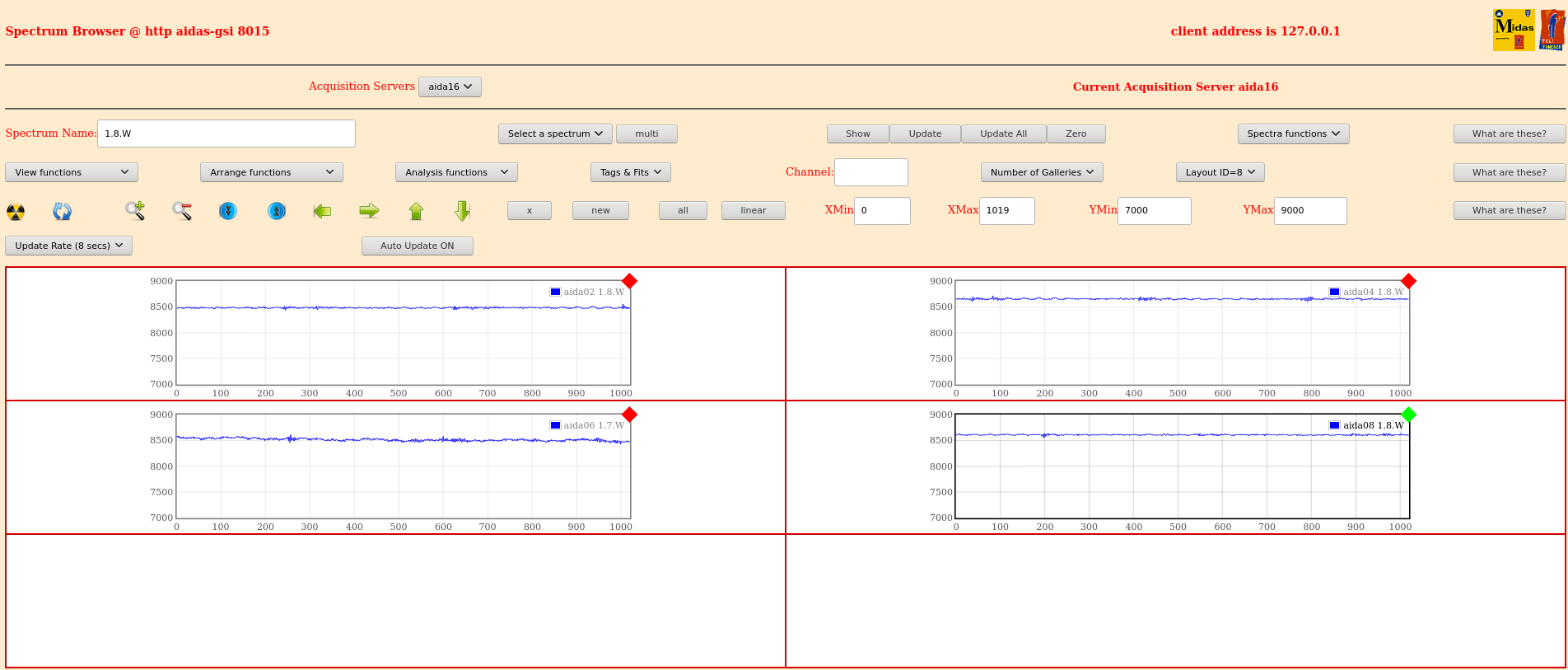
Fig 15-16: Intermediate HV cables re-added
- signal worse in FEE64s with HV cables
- aida09, aida01, aida10, aida13, aida05, aida14 don't have HV interconnect cables, look good

Conclusion: We see noticeable improvements removing the interconnect cables between FEE64s.

Pulser widths now:
- aida14 (-ve amplitude) = 13.5 channels
- aida08 (+ve amplitude) = 40 channels (?) |
| Attachment 1: Screenshot-Waves1.png
|

|
| Attachment 2: Screenshot-Waves2.png
|

|
| Attachment 3: Screenshot-Pulsers.png
|

|
| Attachment 4: Screenshot-Width11.png
|

|
| Attachment 5: Screenshot-PulserWidthBack.png
|

|
| Attachment 6: Screenshot-Width02.png
|

|
| Attachment 7: Screenshot-PulserInRemov-Front.png
|

|
| Attachment 8: Screenshot-PulserInRemov-Back.png
|

|
| Attachment 9: PulserAllOut-Front.png
|
|
| Attachment 10: PulserAllremov-Back.png
|

|
| Attachment 11: HVJumpers-Front.png
|

|
| Attachment 12: HVJumpers-Back.png
|

|
| Attachment 13: AllHVRemoved-Front.png
|
|
| Attachment 14: HVout-Back.png
|
|
| Attachment 15: HVintermediate-Front.png
|

|
| Attachment 16: HVintermediate-Back.png
|
|
|
404
|
Mon Mar 7 12:20:26 2022 |
NH, TD | AIDA Grounding Checks Mon 7 Mar |
Remove all DSSD ribbon cable braid ground from FEE64s to check n+n ground loops
Removing all on n+n side only and test resistance to ground: 4, 6 and 8 show continuity to ground, 2 shows no connection (braid ring terminal to copper bar)
Remove all p+n braids as wll and check:
- See no continuity to ground (good)
- Snout has no continuity to ground (good)
- n+n side fees 4 and 8 to seem to have continuity to snout though (bad)
- p+n checked and don't seem to have continuity to gnd (except when braid was touching a LEMO barrel)
- n+n aida06 maybe has high resistance connection to ground (bad) or (about 0.7 V drop according to RS multimeter)
Bias+Power up and check noise
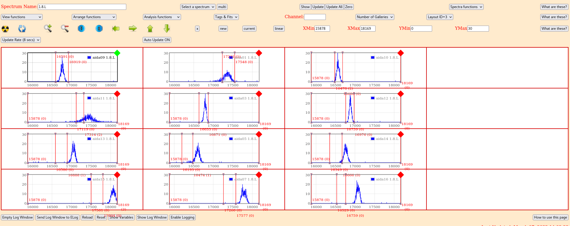
aida09 Peak width = 86.03+/- 1.721
aida02 Peak width = 509.48+/- 11.1812
Low frequency noise on wavesforms corresponds to ca 100 kHz - switching power supply?
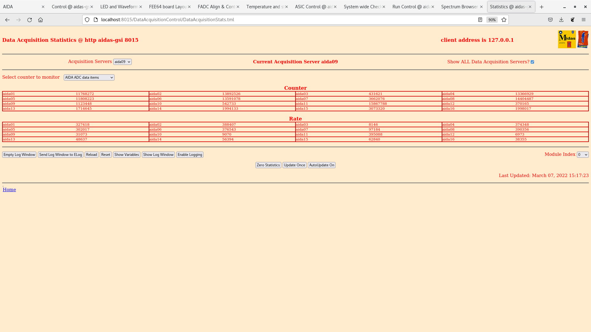
Attachment 6 - ADC data item stats
all p+n/n+n cable braids disconnected
all FEE64 adaptor PCBS grounded to Copper busbar OK
Remove guard ring jumper on upper-middle p+n FEE (rear guard ring of middle DSSSD)
Attachment 7 - ADC data item states
No real change to rates
Remove field plate jumpers on all p+n FEEs
Attachment 8 - ADC data item states
No real change to rates
Remove bias LK1 jumpers on n+n FEES:
Generally worse across the p+n side, no real change to n+n side
Attachment 9 - Stats with LK1 removed:
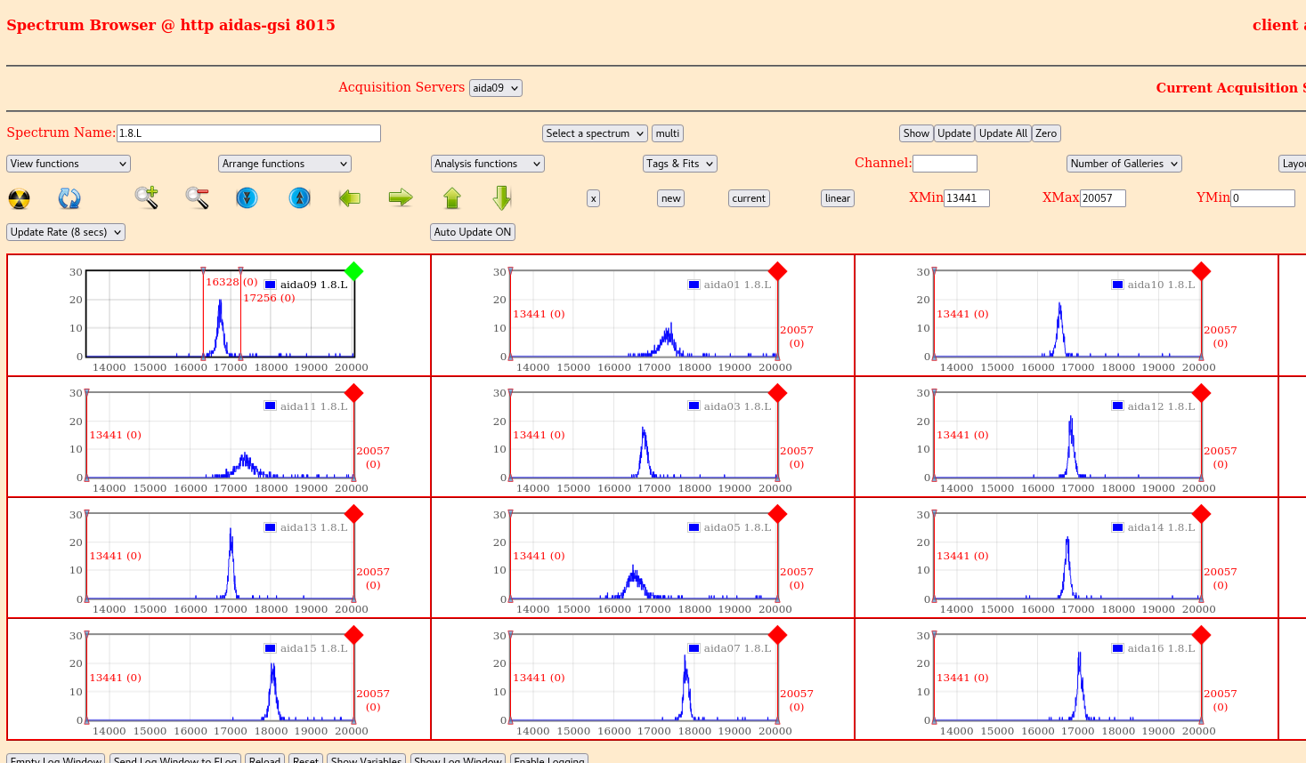
aida09 Peak Width = 181.77. p+n see Attachment 10
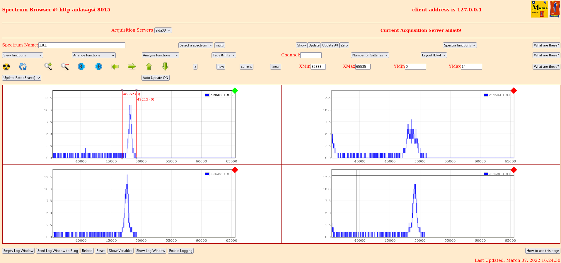
aida02 Peak width = 505.23. n+n see Attachment 11
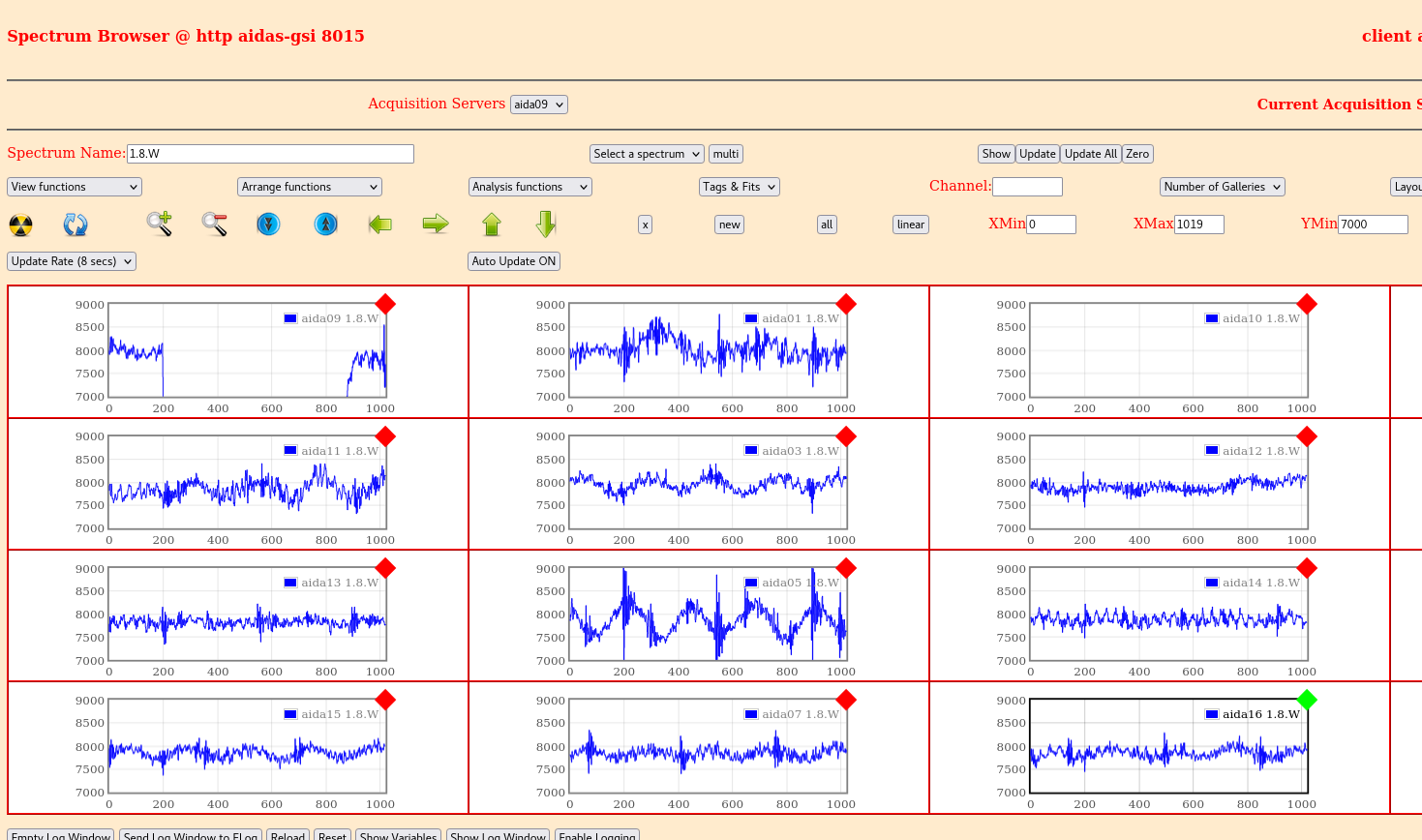
Attachment 12 - p+n waveforms
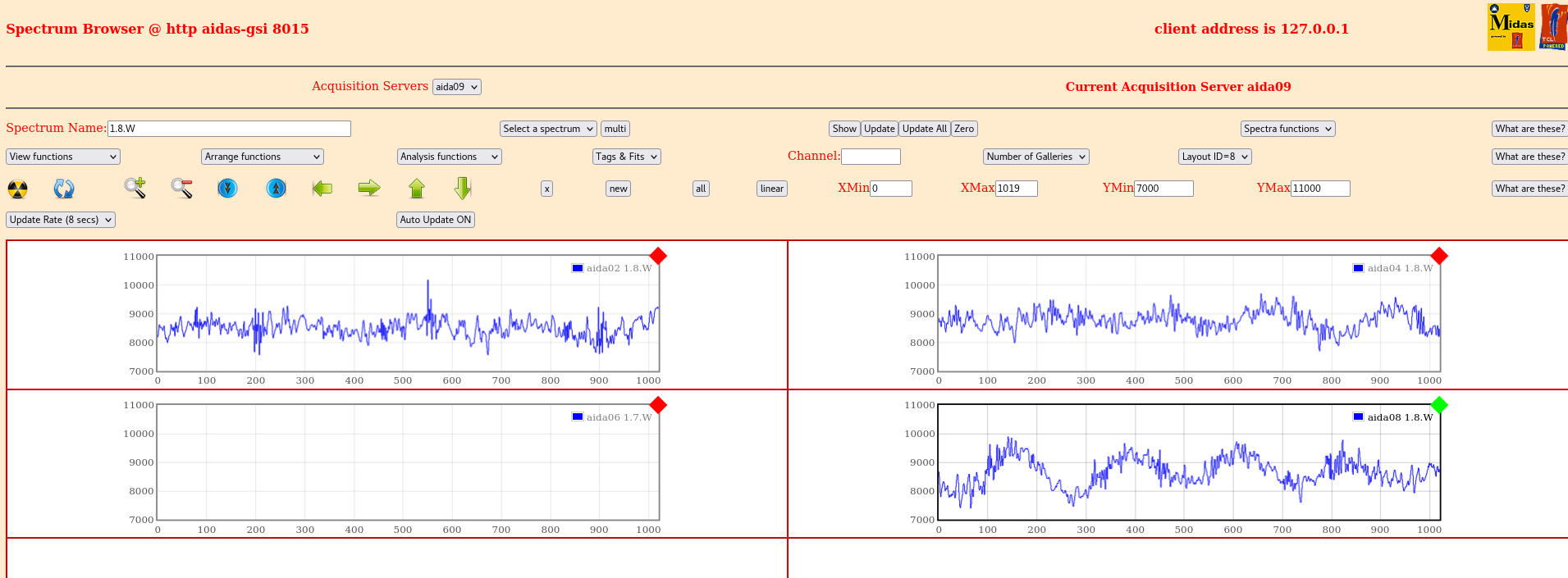
Attachment 13 - n+n waveforms
High frequency component reduced but 100 kHz low frequency component stronger
Remove LK3 from aida03,aida07 (no jumpers at all on any FEE) - DSSSDs floating
No significant change, see attachment 14 stats |
| Attachment 1: 2022-03-07_14-00_Stats.png
|

|
| Attachment 2: 2022-03-07_14-03-03_pn_widths.png
|
|
| Attachment 3: 2022-03-07_14-04-13_nn_widths.png
|

|
| Attachment 4: 022-03-07_14-05-12_pn_waves.png
|

|
| Attachment 5: 2022-03-07_14-05-49_nn_waves.png
|

|
| Attachment 6: Screenshot_from_2022-03-07_15-28-41.png
|
|
| Attachment 7: 2022-03-07_15-48-02_stats_no_middle_rear_GR.png
|

|
| Attachment 8: 2022-03-07_16-08-11_stats_no_fieldplane_ground.png
|

|
| Attachment 9: 2022-03-07_16-22-00_stats_no_LK1.png
|

|
| Attachment 10: 2022-03-07_16-23-50_pn_widths_no_lk1.png
|
|
| Attachment 11: 2022-03-07_16-24-55_nn_widths_no_lk1.png
|
|
| Attachment 12: 2022-03-07_16-25-50_pn_waves_no_lk1.png
|
|
| Attachment 13: 2022-03-07_16-27-09_nn_waves_no_lk1.png
|
|
| Attachment 14: 2022-03-07_17-12-34_no_detector_gnd__stats.png
|

|
|
474
|
Tue May 31 09:05:00 2022 |
NH, TD | Tuesday 31 May |
DSSD stack will be as follows

1      3208-7  1019       125              upstream
2      3208-13 1020       120              downstream

First start checking bias pins on both detectors
These are pins on the *bottom right* of each 68 pin connector (C-2299)
Expect finite resistance

3208-7:
  Top and bottom: 22 Ohm
  Left and right: 22 Ohm

3208-13:
  Top and bottom: 22 Ohm
  Left and right: 22 Ohm

Conclusion: All bias bond wires are intact on both DSSDs

Visual inspection is both DSSDs look good with no damage or bond wire issues

Installed in snout: full stack

3 mm bPlas 1
17 mm Air
1 mm AIDA 1  (645 mm from base of snout)
9 mm Air
1 mm AIDA 2 (655 mm from base of snout)
12 mm Air
3 mm bPlas 2 |
|
56
|
Mon Jul 8 16:02:52 2019 |
NH, PJCS | Aida 28/6/2019 - WATER OFF |
It occurs to to wonder if there is now water inside the modules. If the metal of the cooling plates is damp on the outside then it is safe to assume there is water on the inside too . Can I suggest that one of the modules is dismounted, disassembled and checked?
Patrick
| Quote: |
|
The humidity sensor hasn't reported humdities under 90% yet. In order to try and help dry the pipes and turn AIDA the water has been turned off the weekend.
Sunday temperatures might reach 40 C which means it may struggle anyway.
Will consider trying to get a temperature/humidity monitor for S4 to check if the environment is fine too.
|
|
|
127
|
Wed Feb 19 10:58:29 2020 |
NH, PJCS | Report: aida09 Kernel Panic & Lost WR |
> aida09 crashed over the weekend and automatically rebooted.
> After the reboot the WR timestamp sent to the merger is in the future and hence incorrect
>
> Reset/Setup did not fix issue
> Sync ASICs did not fix issue
> GSI White Rabbit control page shows a correct WR timestamp
>
> Attach 1: ttyUSB12 (aida09 log with kernel panic)
> Attach 2: GSI White Rabbit control page
> Attach 3: "Collect All WR Timestamps"
> Attach 4: RAW Display for aida09
>
> WR Time Item 0x80500232 0x0de48000; Time (48:63)=0x232; Time (28:47)=0x20310; Time (0:27)=0x0de48000
> WR Time Item 0x80420310 0x0de48000; Time (28:47)=0x20310; Time (0:27)=0x0de48000
>
> WR Timestamp = 0x23220310de48000 * 10 = 0x15F541EA 8AED0000 = 2020-02-21 CET 01:01:59.699537920
> c.f. "GSI page" timestamp starting 0x15F427F5
>
> Attach 5: Timestamp shown by merger

Tested aida01 and aida09 today ( 19/2/2020 ) and both make sense relative to their Timestamps.
It is the case that the WR timestamp from the "GSI White Rabbit Timestamp" browser window is direct from the White Rabbit decoder and as such has an LSB of
1nS and is captured at T0 time ( 10uS intervals ) whereas the timestamp of the SYNC in the raw data display is 10nS LSB and is captured at the time of a
logical "rollover" of the lower 14 bits of this 10nS timestamp.


Is it the case that the system has been power cycled since aida09 got its timestamp wrong ?


It is possible to reset an individual FEE64 WR decoder by writing 0x80 into register 0 of the individual "GSI White Rabbit Timestamp" page. Then 0x1 to re-
enable the decoder.
This should never be necessary as the decoder should be collecting the latest timestamp continuosly.

The statement remains true however that if the Linux in a FEE64 has a "Panic" then the FEE64 must be powercycled in order for the subsequent data to be
considered reliable.
The Raspberry Pi Console control browser will count the number of "Panics" in the console logged text files so they can be monitored.

If this occurs again then the system wide check results would be interesting. |
|
433
|
Thu May 12 16:30:47 2022 |
NH, OH, TD | Notes for mounting a second switch |
Update DHCPD as expected
Make sure new ethernet device is trusted in firewall
Make sure hosts is updated
make sure /home/Embedded/XilinxLinux/ppc_4xx/rfs/aida08/etc/hosts "myserver" points to correct ip address
make sure /MIDAS/linux-ppc_4xx/startup/aidaXX has netvar "TS_Server" pointing to correct ip address
Update the IP in /MIDAS/linux-ppc_4xx/startup/aida* |
|
93
|
Tue Nov 12 13:59:07 2019 |
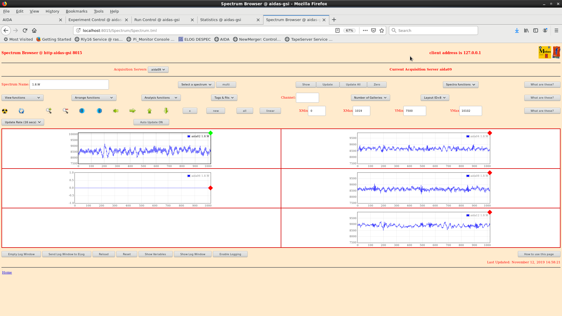
NH, OH, CA | Awfully noisy waveforms |
Rates in all FEEs much higher than before - waveform shows very noisy in all systems. - attachment 1

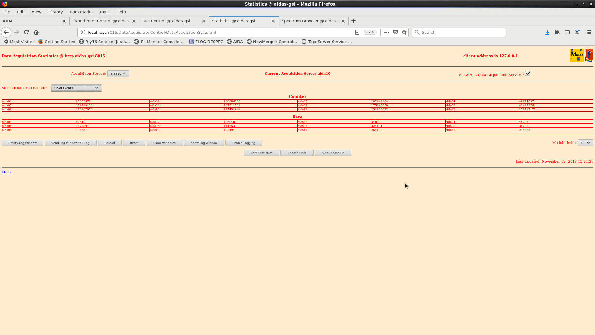
Good event statistics - attachment 2

DISC in 7 and 3 above 300k

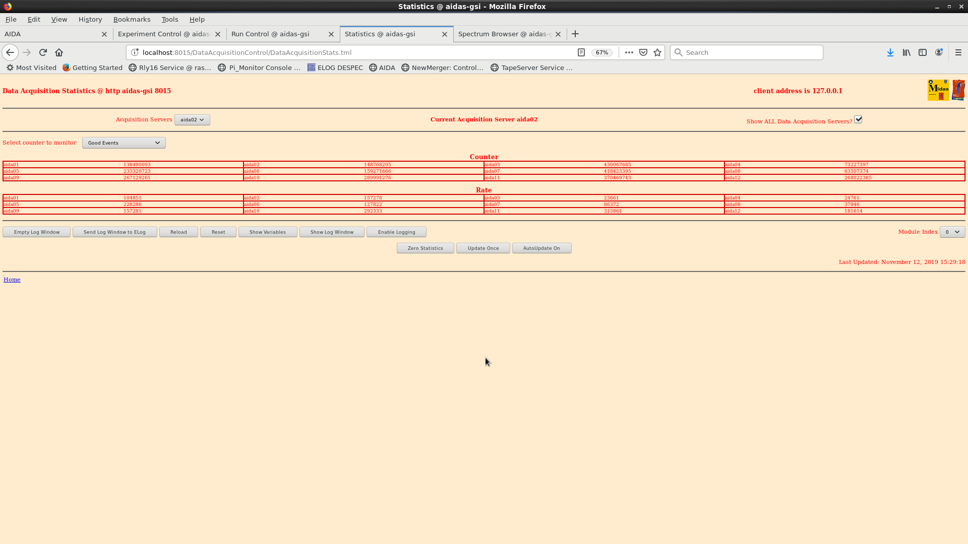
ASIC check load performed.

Good event statistics - attachment 3

Thesholds at 0xa for all FEE

Disc rate now 0 across all FEE


Pulser settings: attachment 4

pulser peak widths -   FEE         width(ch)
                              1             128
                              2             145
                              3             84
                              4             74
                              5             207
                              6             125
                              7             172
                              8             80
                              9             193
                              10            183
                              11            238
                              12            138

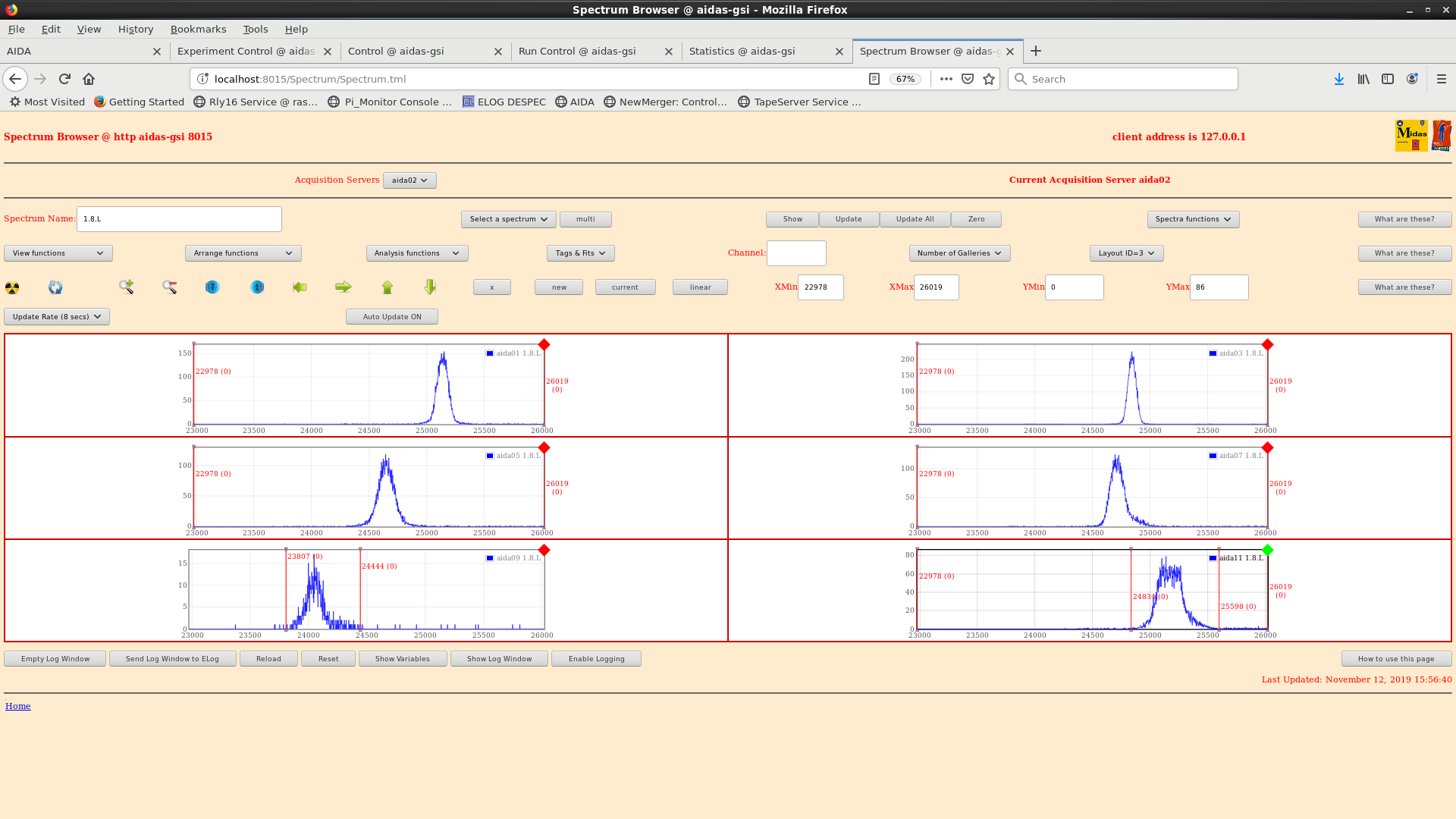
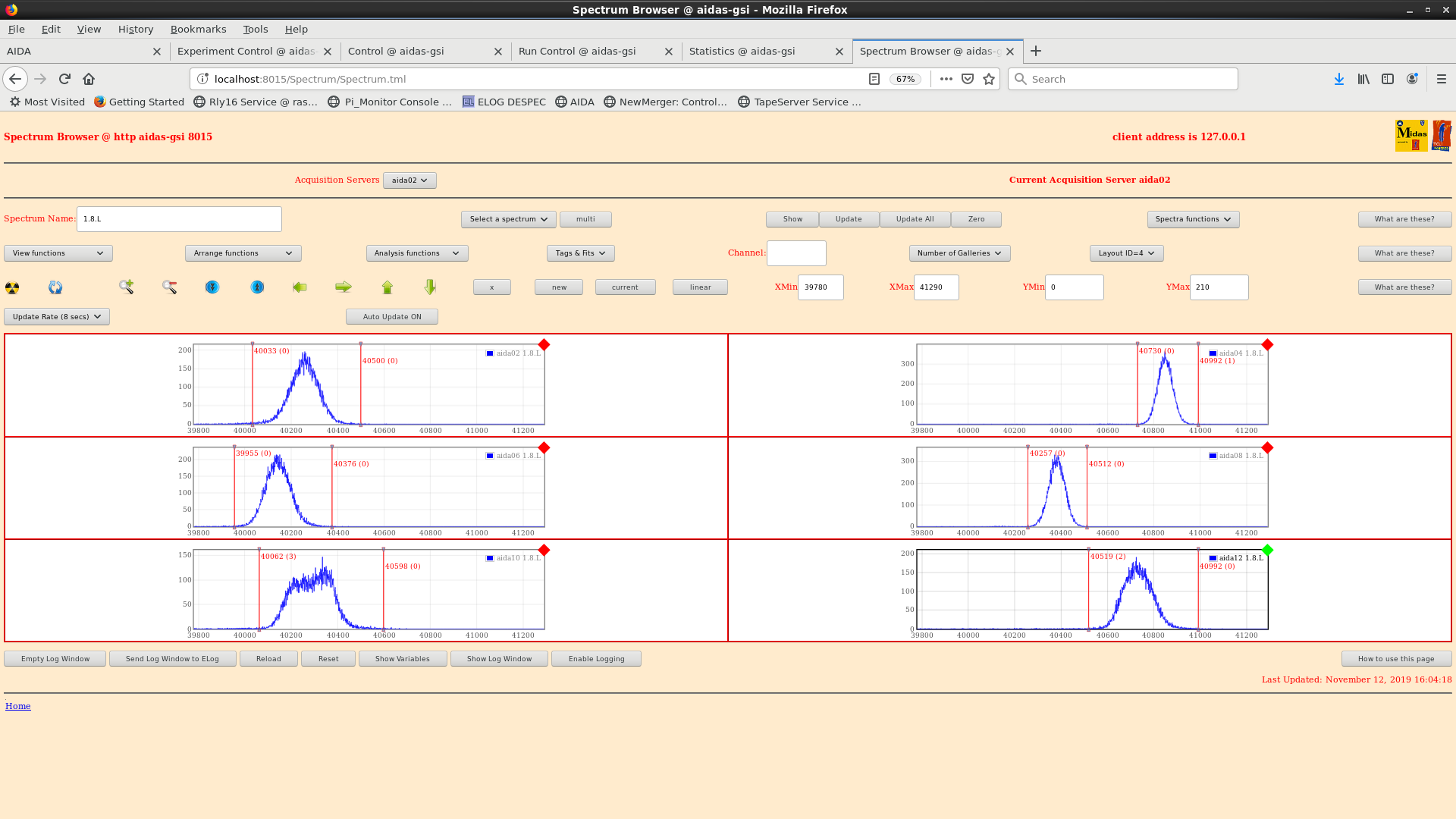
Attachments 5 & 6: pulser peaks for all FEE64

16.24: DAQ stop

       slow comparator threshold changed to 0x64

       ASIC check performed

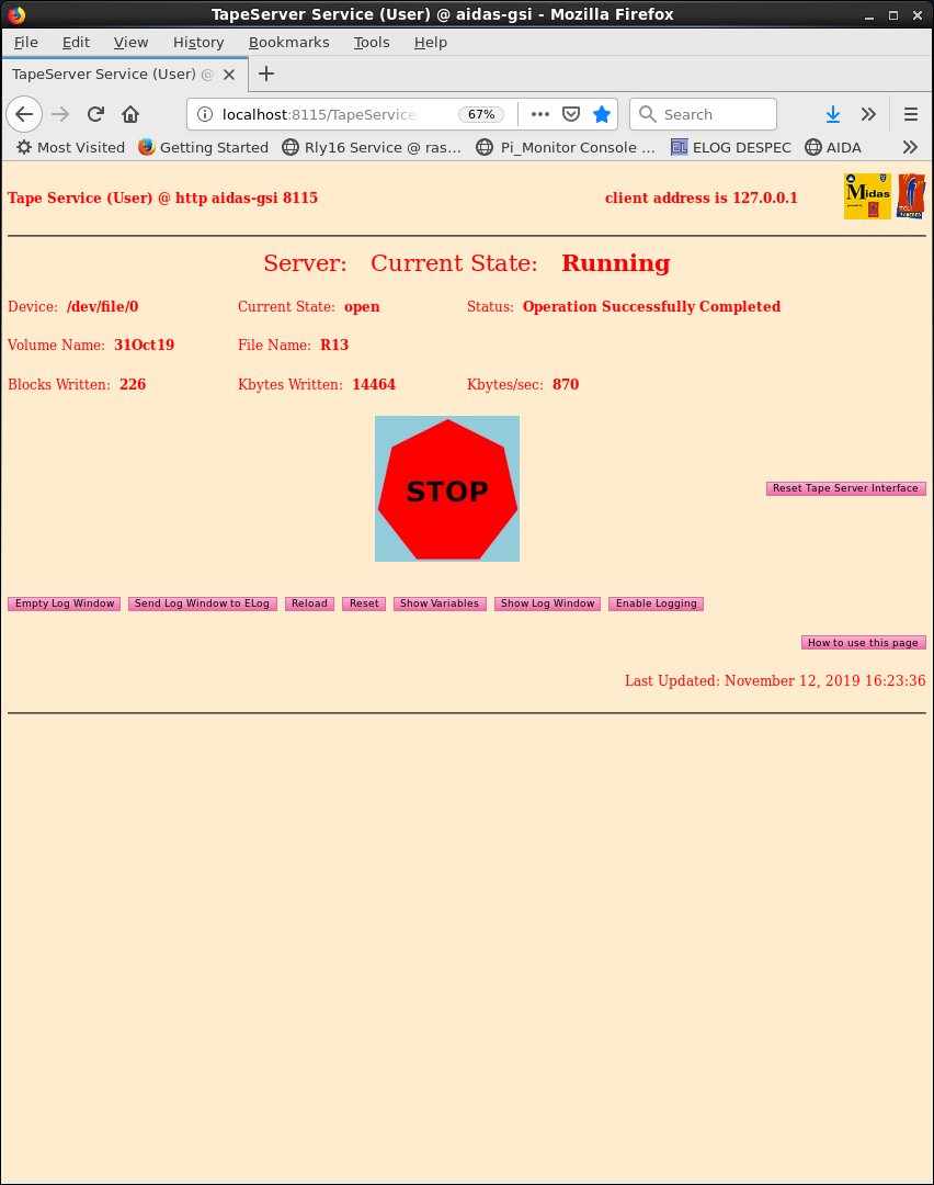
       Alpha run/DAQ start (w/ data transfer enabled) - writing to file 31Oct19/R13

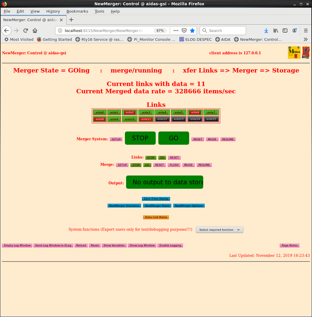
Merger and TapeService ok - attachments 7 & 8 |
| Attachment 1: awfulwaves121119.png
|
|
| Attachment 2: 191112_GoodEvents.png
|
|
| Attachment 3: 191112_StatsPostLoad.png
|
|
| Attachment 4: pulsersettings191112.png
|

|
| Attachment 5: pulserpeaksOdd.png
|
|
| Attachment 6: pulserpeaks_Even.png
|
|
| Attachment 7: merger191112.png
|
|
| Attachment 8: tapeservice191112.png
|
|
|
94
|
Tue Nov 12 14:10:18 2019 |
NH, OH, CA | Aida10 Unusual Pulser Peak |
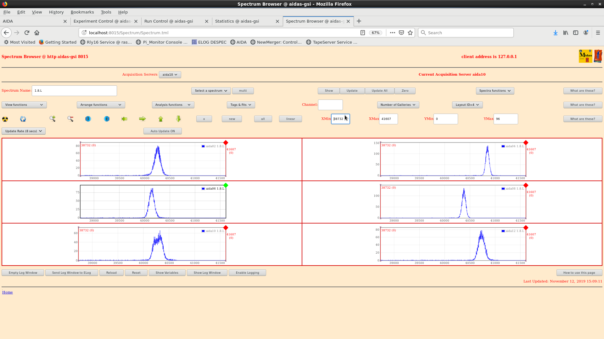
aida10 (no alpha rate recorded) has a strange pulser peak - looks like double peak?
Pulser terminator checked and OK...
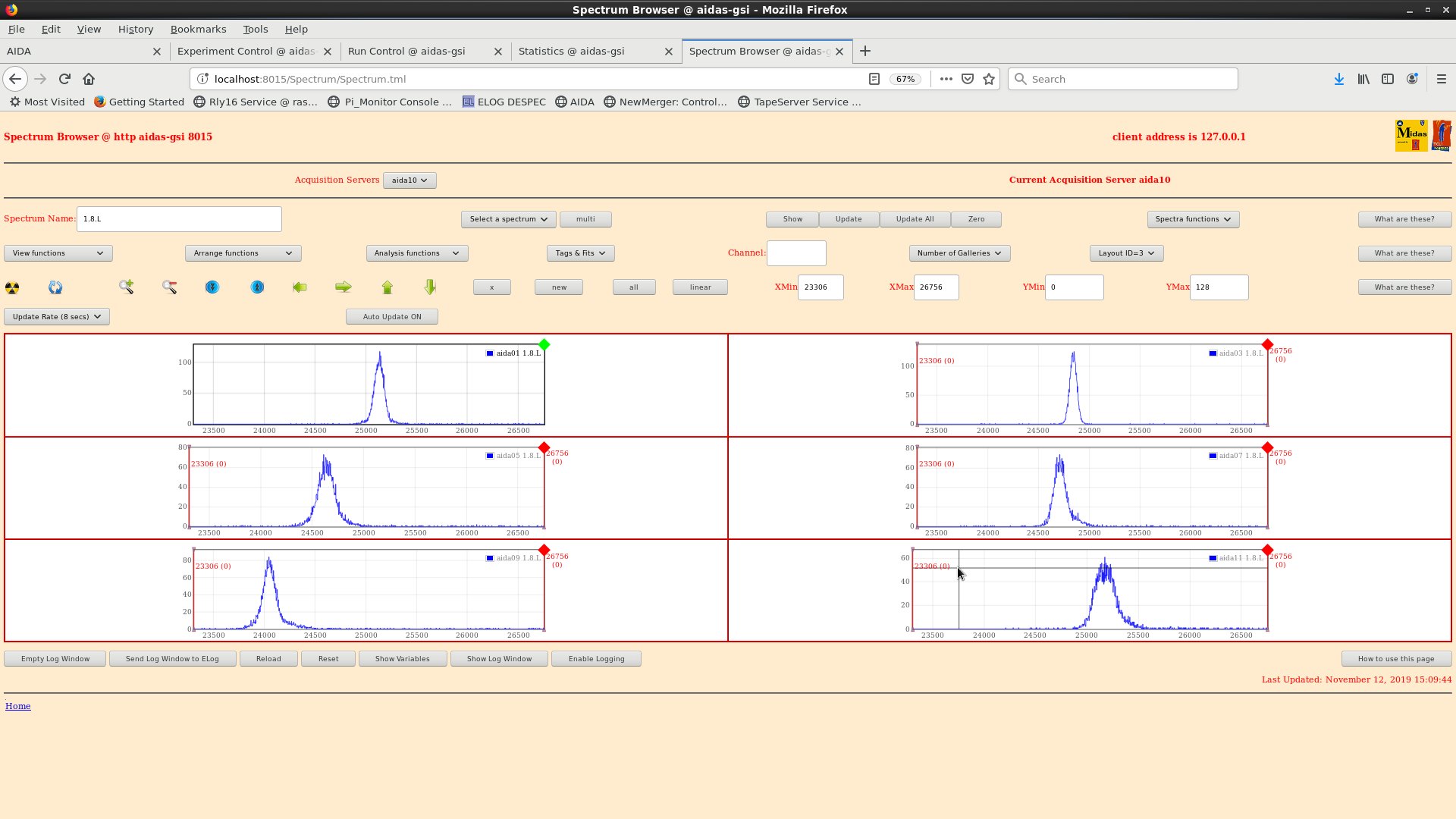
All others "OK" but noise quite bad (see previous entry) |
| Attachment 1: aida10-pulser-121119.png
|

|
| Attachment 2: pulsers121119.png
|
|
| Attachment 3: pulsersodd121119.png
|
|
|
385
|
Wed Oct 20 13:26:08 2021 |
NH, OH | AIDA Noise + Filtering |
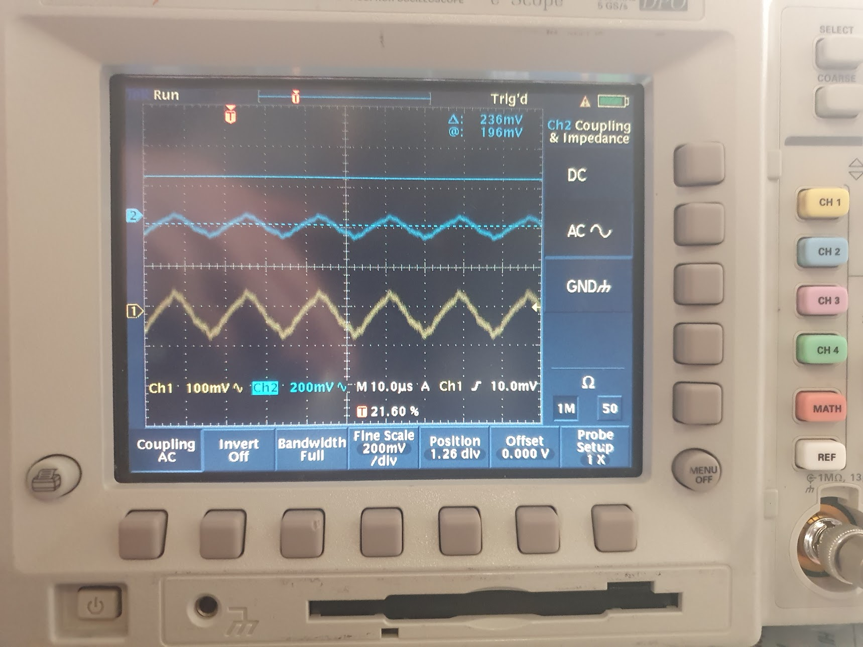
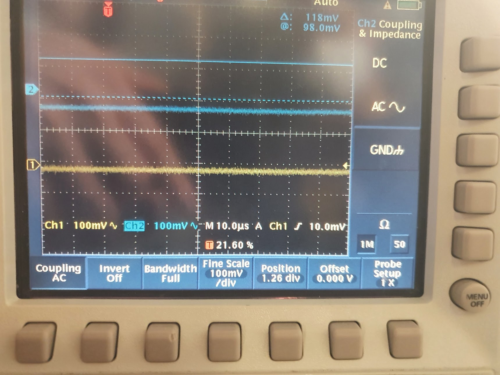
Turn on AIDA (SL6) to investigate noise situation and impact of new RC filters on bias input
Current setup:
- No Detectors
- Pulser in fee14, fee8 *only*, no bias connected. FEEs isolated from each other
Pulser widths::
p+n grounds connected via bias link (no connection to HV bias itself)
|
ASIC | FEE14 Width | FEE8 Width
| |
1.8.L | 14.41 | 21.86
| |
2.8.L | 13.02 | 21.87
| |
3.8.L | 12.57 | 21.52
| |
4.8.L | 13.75 | 23.59
|
Note: FEE8 is connected via SA1 inverter -> cause of worse resolution
Plug bias into outer FEEs (14 + 8 + chaint o 6)
|
ASIC | FEE14 Width | FEE8 Width
| |
1.8.L | 14.59 | 24.43
| |
2.8.L | 12.73 | 22.25
| |
3.8.L | 12.76 | 23.06
| |
4.8.L | 14.36 | 23.31
|
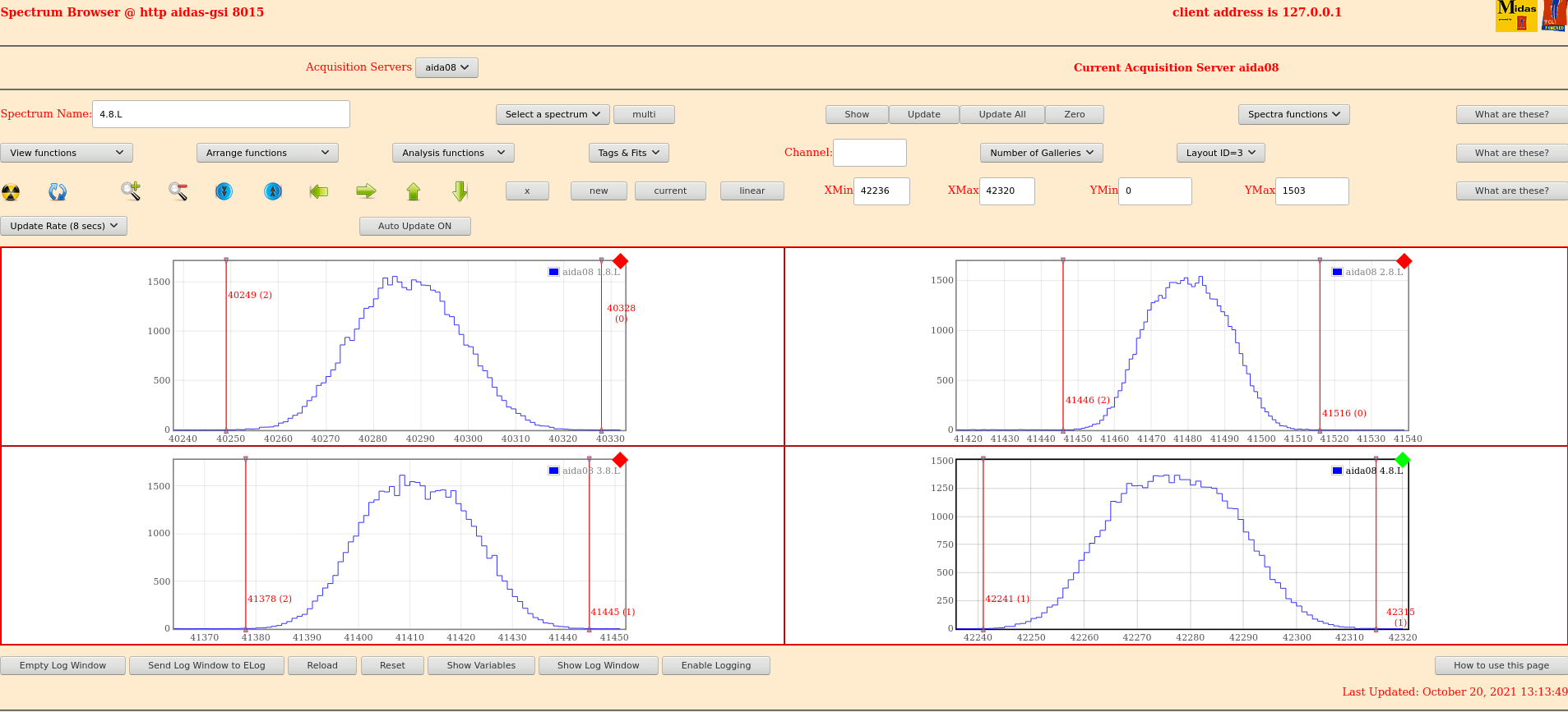
Long run over lunch:
|
ASIC | FEE14 Width | FEE8 Width
| |
1.8.L | 14.47 | 25.52
| |
2.8.L | 12.83 | 24.26
| |
3.8.L | 12.75 | 24.15
| |
4.8.L | 14.58 | 26.93
|
Figures 1 & 2
Add HV filters
|
ASIC | FEE14 Width | FEE8 Width
| |
1.8.L | 14.34 | 23.53
| |
2.8.L | 12.67 | 23.82
| |
3.8.L | 12.78 | 23.59
| |
4.8.L | 13.88 | 25.76
|
Figures 3 & 4
Small improvement maybe?
Figs 5&6 - Oscilloscope before & after HV filter added
--
Plans for tomorrow (21/10/21)
- Reintroduce pulser cables through all FEEs to see impact on noise (maybe improved now)
- Measure pulser noise in battery DSO (+ other sourceS?)
- Add a DSSD and see impact on noise with HV filter
- Resistance from FEE64 adapter to mechanical ground
- Check pulser on the battery powered scope (Is the signal common to the power supply) |
| Attachment 1: 211020_1316_fee14_bias_con_long_stats.png
|

|
| Attachment 2: 211020_1314_fee8_bias_con_long_stat.png
|
|
| Attachment 3: 211020_1421_fee14_bias_con_filtered_long.png
|

|
| Attachment 4: 211020_1415_fee8_bias_con_filtered_long.png
|

|
| Attachment 5: scope_before.png
|
|
| Attachment 6: scope_after.png
|
|
|
509
|
Wed Jun 29 10:48:26 2022 |
NH, OH | AIDA Dismounted |
All detectors removed from single and triple AIDA snouts

Empty snouts *and* DSSDs (in boxes) stored in NH office |
|
545
|
Fri Mar 22 07:34:54 2024 |
NH, JB | Au Beam |
|
|
550
|
Tue Mar 26 10:32:05 2024 |
NH, JB | Tue 26 March |
Taken 4 FEE64s from CRYRING (the 4 easiest to access)
  41:d8:2b
  41:f6:5a
  41:ee:71
  41:d0:0e

In addition a FEE without rails marked only 20 was found in my old office for 5
- This probably came in a shipment to/for repairs

DSSSD#1 unbiased

DESPEC Platform moved out of beam and gamma platform moved from AIDA
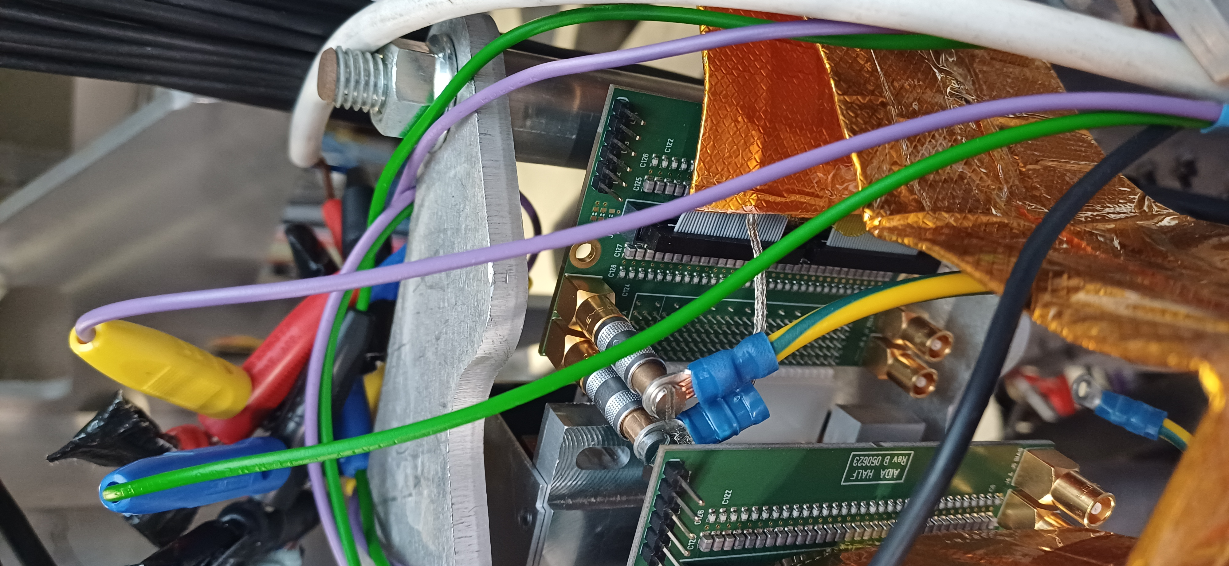
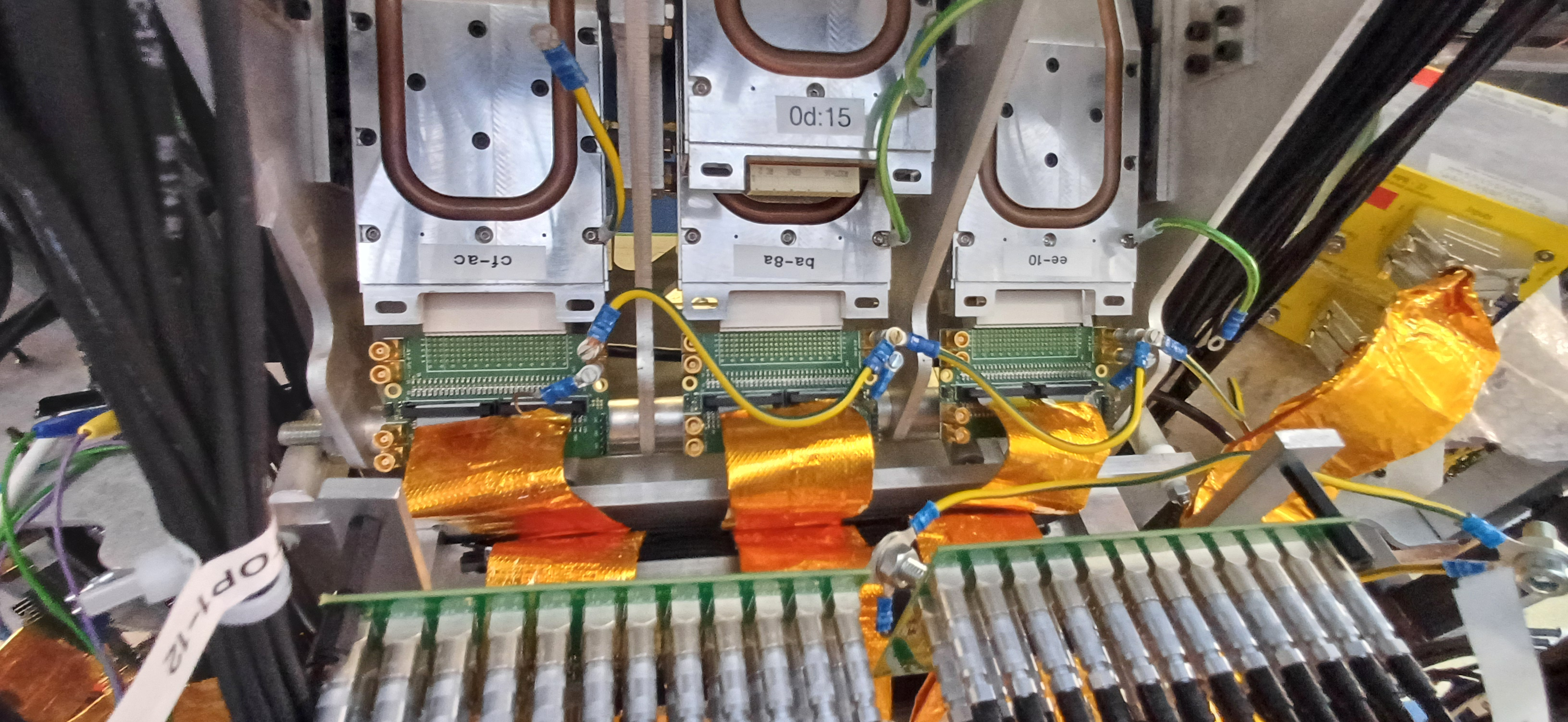
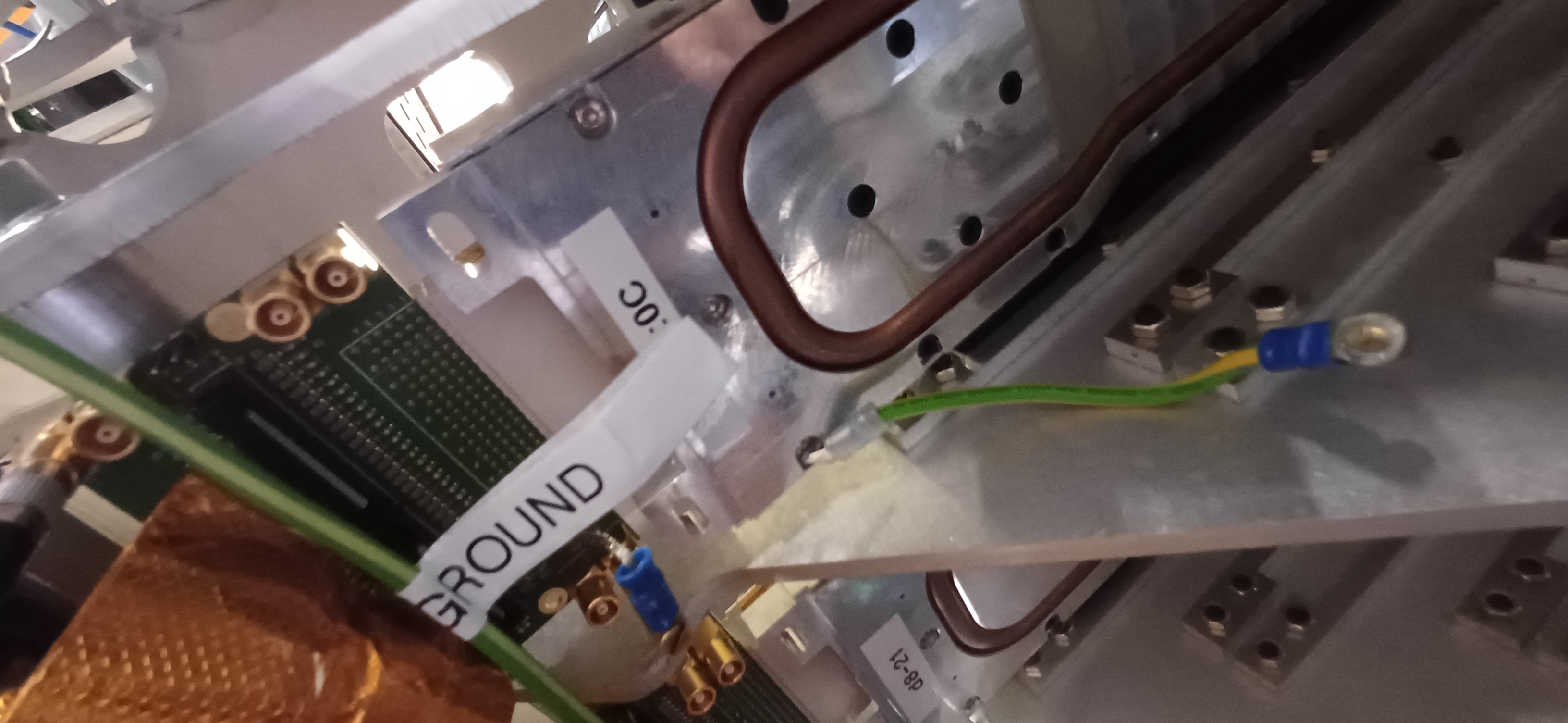
JB works on grounding the original 8 DSSSD#1 FEEs

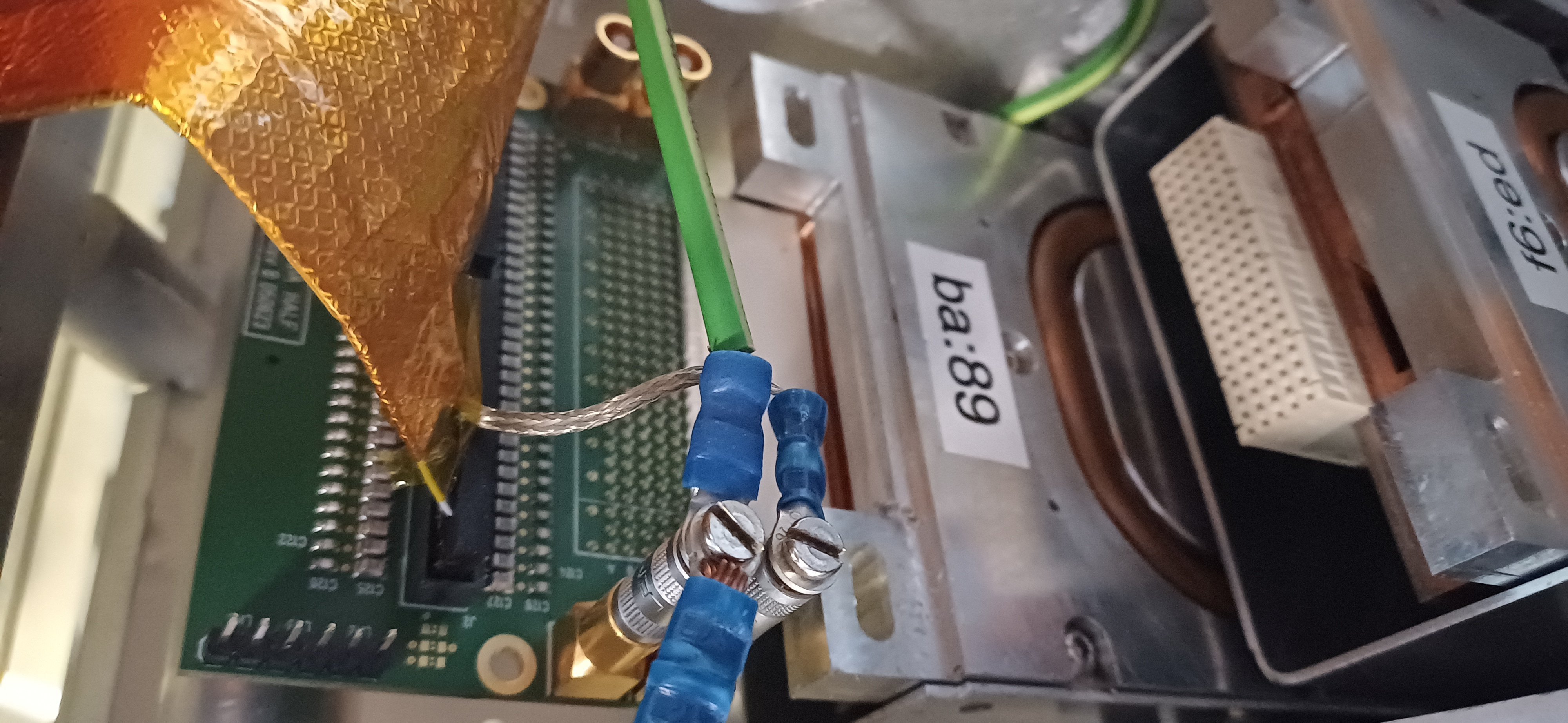
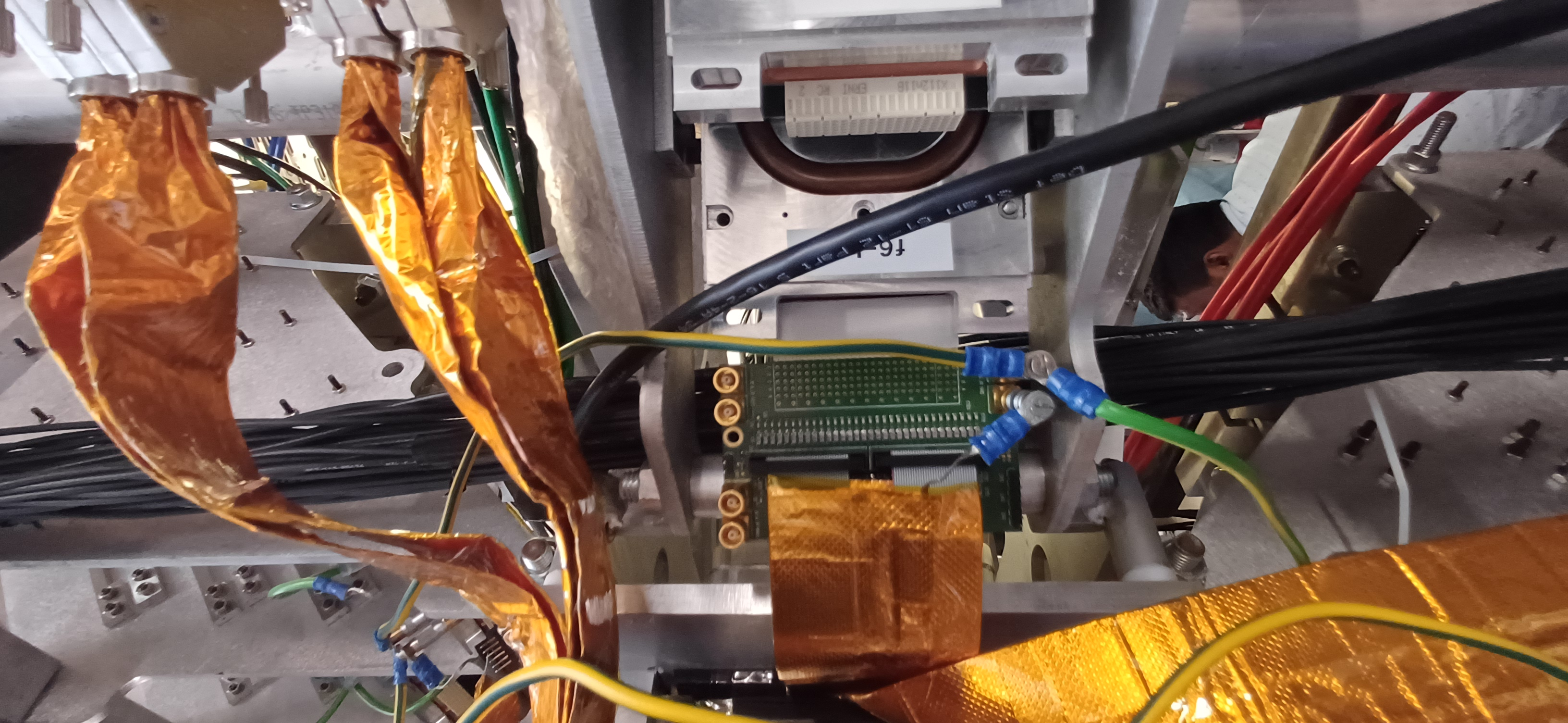
Connected grounding from ribbon cable drain to adapter PCB
Ground loop connected

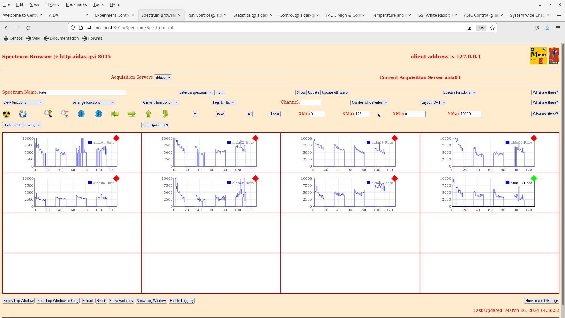
AIDA rates unchanged bad still fig 1
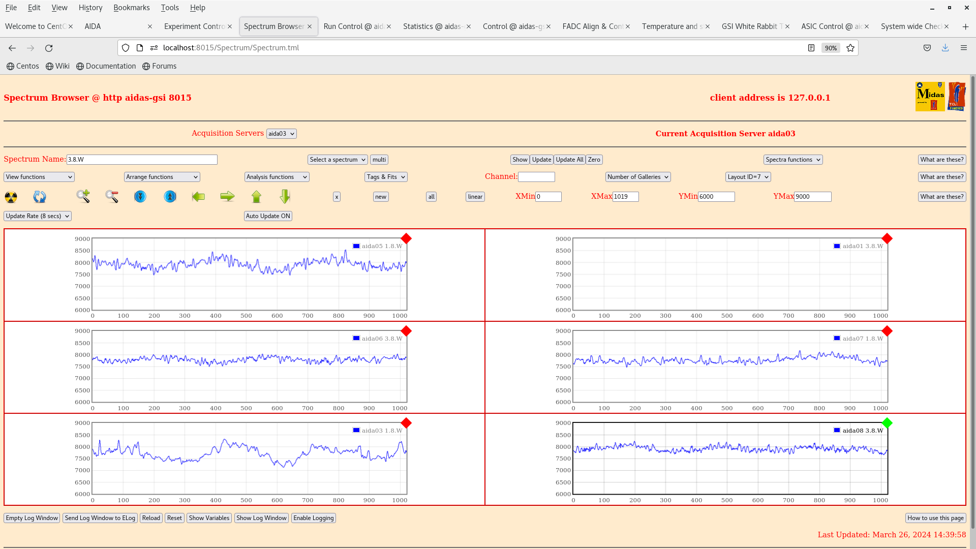
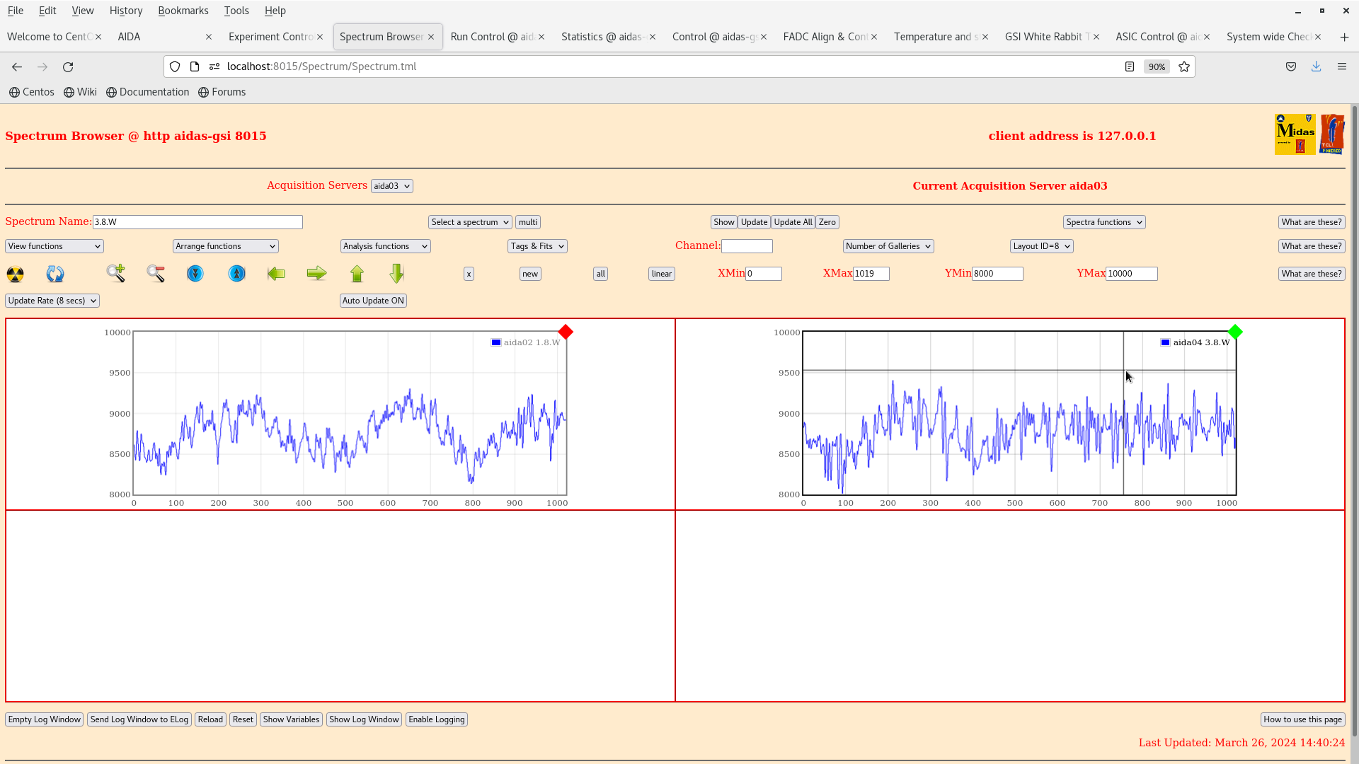
Waves fig 2 (p+n 6000-9000)
Waves fig 3 (n+n 8000-10000)
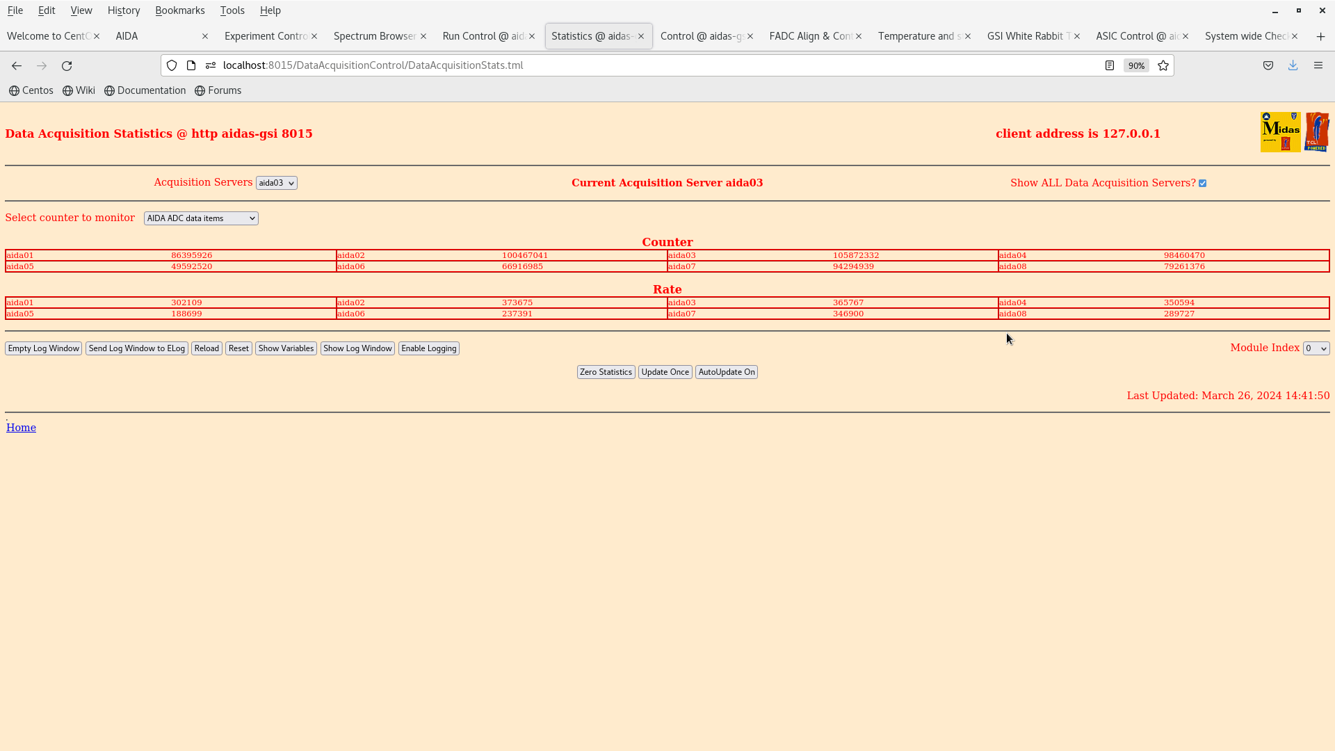
Statistics fig 4 |
| Attachment 1: Screenshot_from_2024-03-26_14-39-35.png
|
|
| Attachment 2: Screenshot_from_2024-03-26_14-40-05.png
|
|
| Attachment 3: Screenshot_from_2024-03-26_14-40-30.png
|
|
| Attachment 4: Screenshot_from_2024-03-26_14-41-56.png
|
|
| Attachment 5: 20240326_144539.jpg
|
|
| Attachment 6: 20240326_144638.jpg
|
|
| Attachment 7: 20240326_144528.jpg
|
|
| Attachment 8: 20240326_144659.jpg
|
|
| Attachment 9: 20240326_144627.jpg
|
|
|
213
|
Fri Apr 9 16:45:29 2021 |
NH, HA. GA, GZ, OH, TD | AIDA Noise |
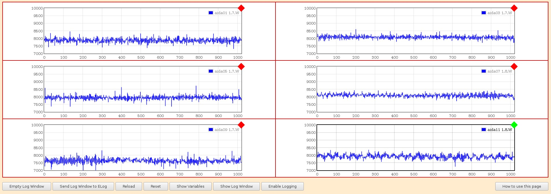
AIDA snout was reconnected and we saw originally a very good reduction in noise from S452 (fig 1)
Occasional bursts of increased rates were noticed, perhaps related to works in S4.

Tape rate at optimal conditions was around 6 MB/s
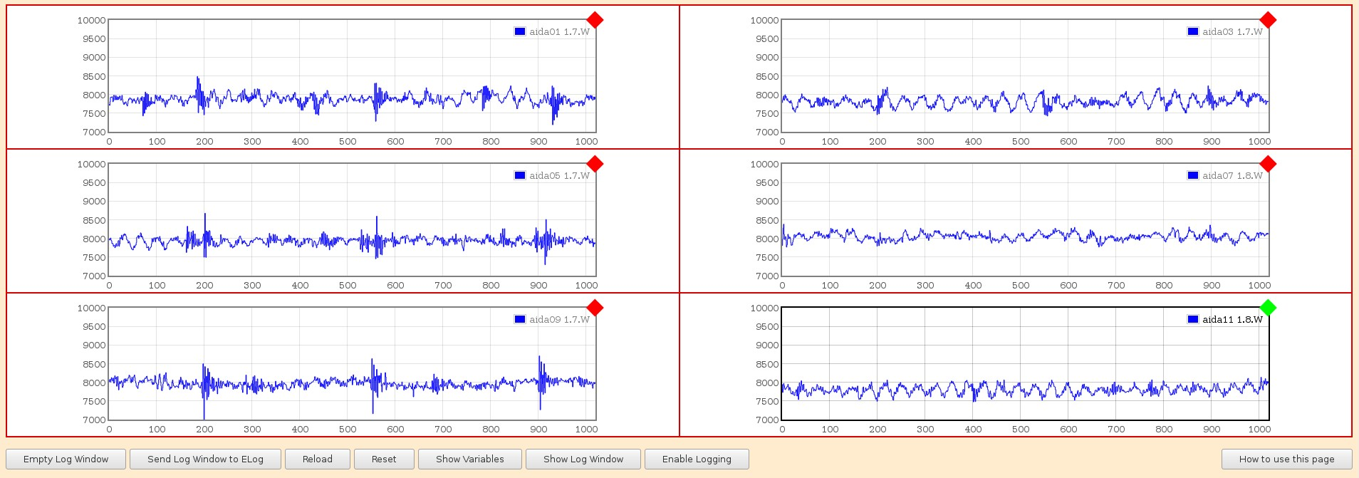
We still saw some extrinsic noise in waves, two frequencies observed : 1.5 MHz and 100 kHz or so

Figs 2, 3 are at 50 MS/s
Figs 4, 5 are at 5 MS/s

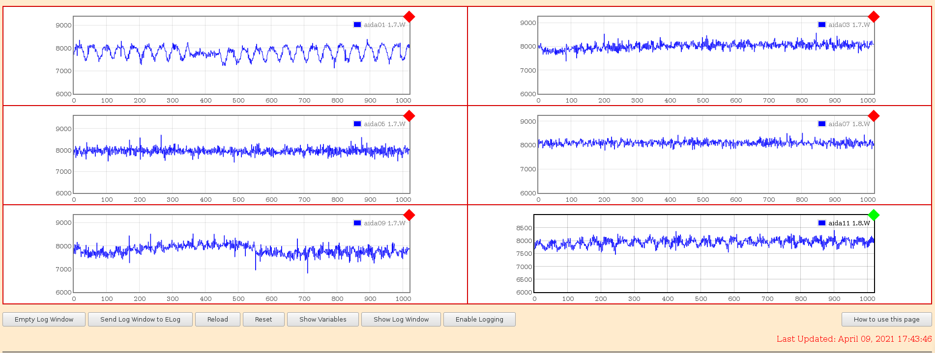
Today the situation has become a lot worse for reasons still unknown.
aida01 shows very strong noise, frequency 125 kHz or so it seems (still at 5 MS/s)
Amplitude 100 mV or so I think

Investigation still underway |
| Attachment 1: Image_Pasted_at_2021-4-7_18-15.png.jpeg
|

|
| Attachment 2: Image_Pasted_at_2021-4-8_16-142.png.jpeg
|

|
| Attachment 3: Image_Pasted_at_2021-4-8_16-14.png.jpeg
|
|
| Attachment 4: Image_Pasted_at_2021-4-8_16-17.png.jpeg
|
|
| Attachment 5: Image_Pasted_at_2021-4-8_16-18.png.jpeg
|

|
| Attachment 6: noise_aida_090421.png
|
|
|
415
|
Wed Apr 27 15:47:46 2022 |
NH, HA, SA, CJ | AIDA 27 Apr 22 |
Remount snout in S4 (photos to come)
Alignment with DEGAS OK but a bit short...  DEGAS platform will be brought 31 mm closer to AIDA by rail adjustment

Can mount bPlas booster boards on old ITEM frames and also partly on AIDA snout (isolated)

-

Reconnect all adapter boards and grounds, bias AIDA...

HV OK. We still have a light leak at the snout endcap. "Fixed" with sheet for now

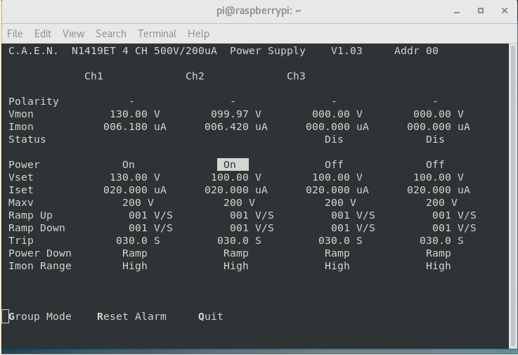
HV leakage currents figure 1

Start AIDA DAQ and check rates.. all seem OK. aida07 is very noisy other p+n good
Notice some issues in aida04, check and ribbon cable slightly loose on one side of adapter
No change to other FEEs.
Aida07 was inspected but nothing obviously wrong

Rates figure 2
Rate spectra figure 3
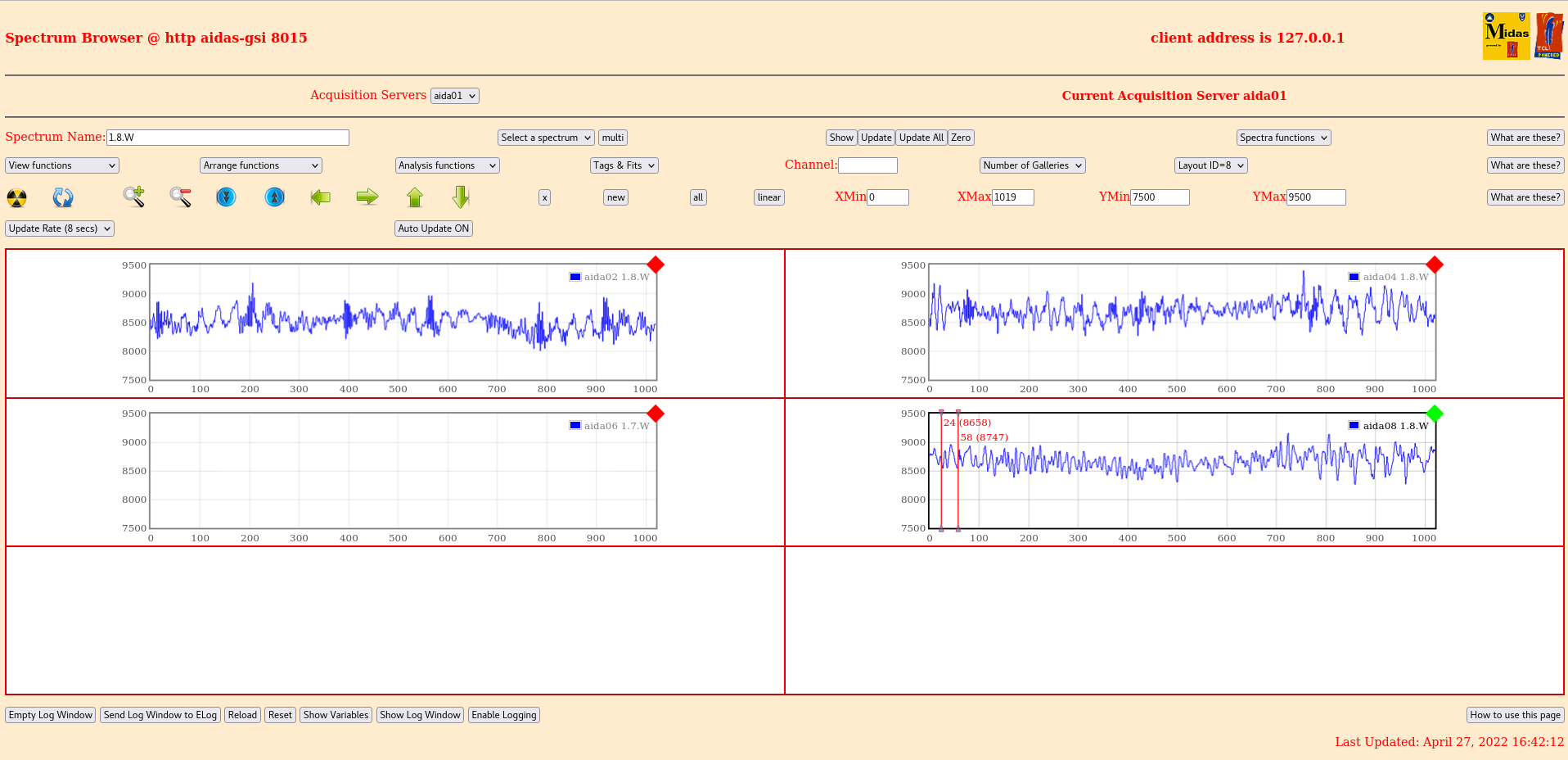
Wavesform figures 4 (p+n), 5 (n+n)
Pulser peak withs
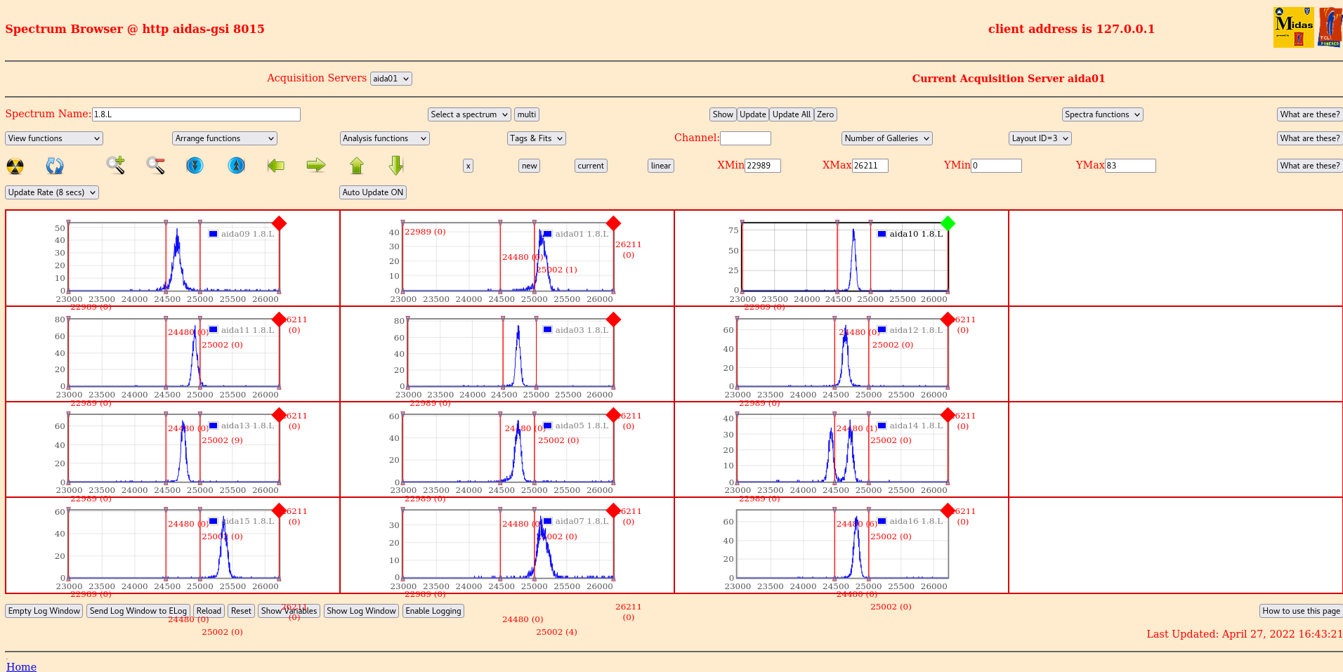
 p+n figure 6, width ~  70 channels (50 keV)
 n+n figure 7, width ~ 570 channels (400 keV)

n.b. double peak in aida14 is an artifact from an uncleared histogram

DSSDs debiased to allow work on bPlas cabling without tripping DSSDs |
| Attachment 1: 2022-04-27_16-42-37_HV.png
|
|
| Attachment 2: 022-04-27_16-39-58_Rates.png
|

|
| Attachment 3: 2022-04-27_16-40-23_RatesSpectra.png
|

|
| Attachment 4: 2022-04-27_16-41-46_pnwaves.png
|

|
| Attachment 5: 2022-04-27_16-42-20_nn_waves.png
|
|
| Attachment 6: 2022-04-27_16-43-30_pn_pulser_70ch.png
|
|
| Attachment 7: 2022-04-27_16-44-18._nn_pulser_568ch.png
|

|
|
674
|
Mon Dec 9 12:28:01 2024 |
NH, CC, MP | Test of BB7 on AIDA Electronics |
BB7 connected to aida07, sitting in a cardboard box

Update Tcl/Tml files in ASIC, ASIC4 and sys.tml frm PJCS email to allow setting per-ASIC polarity on FEE64
Restart MIDAS@8015

Power on all FEEs

Note nnrpi is not responding to ssh... MP investigates if it ahs been unplugged
 No, but a powercycle worked and fixed it

See error: /MIDAS/FEE_ASIC/aida06/ASICs.txt  not found, create the folders

We see some data in the L spectra, and changing the settings from one ASIC seems to work properly

Stopped for CC/MP to determine the which ASICs correspond to p+n and n+n

Follow up: Alpha data overnight or source? |
|
632
|
Wed May 22 20:10:19 2024 |
NH, CC, HMA, MV, ZC, KZ | AIDA Snout Remounted |
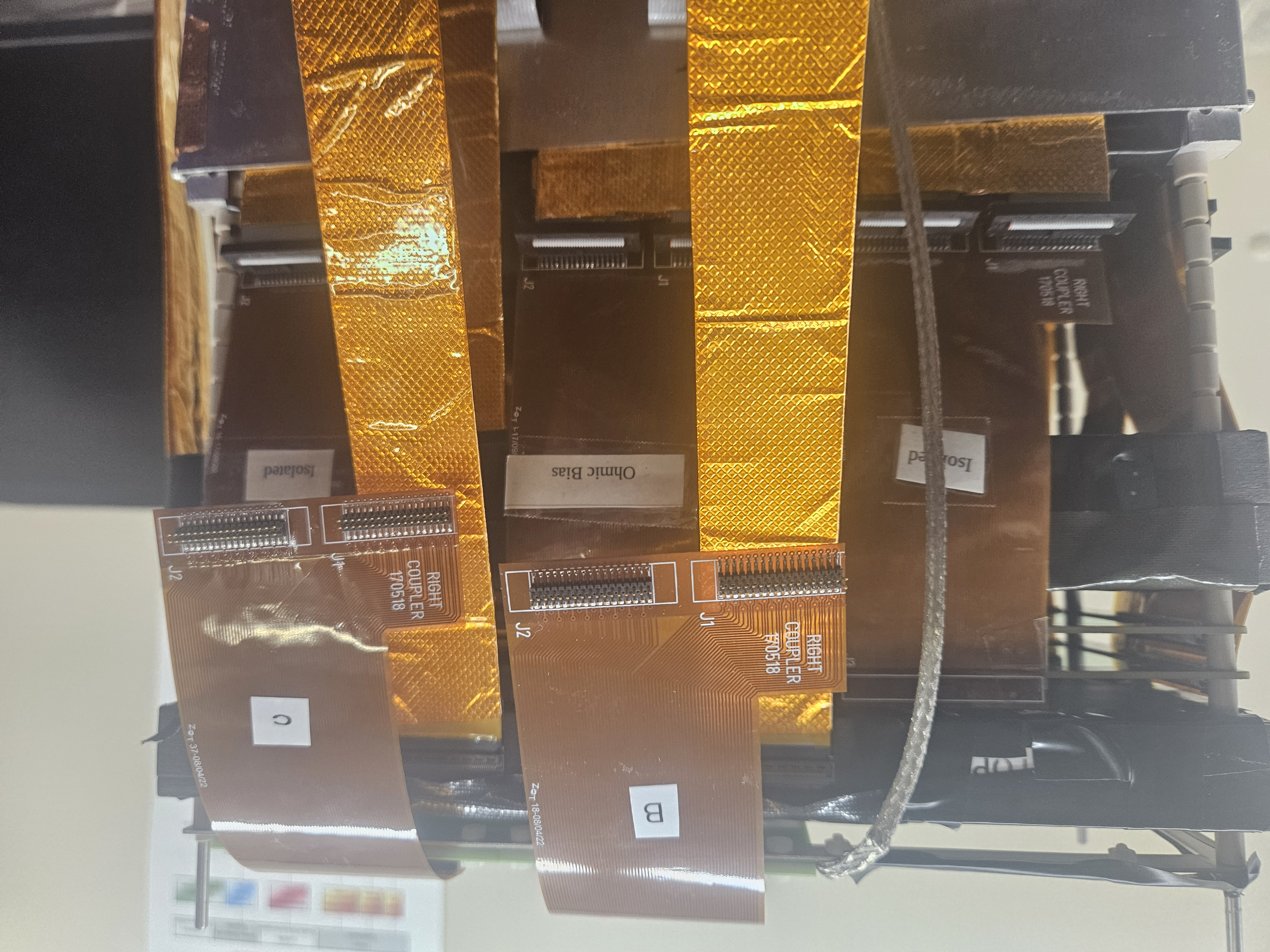
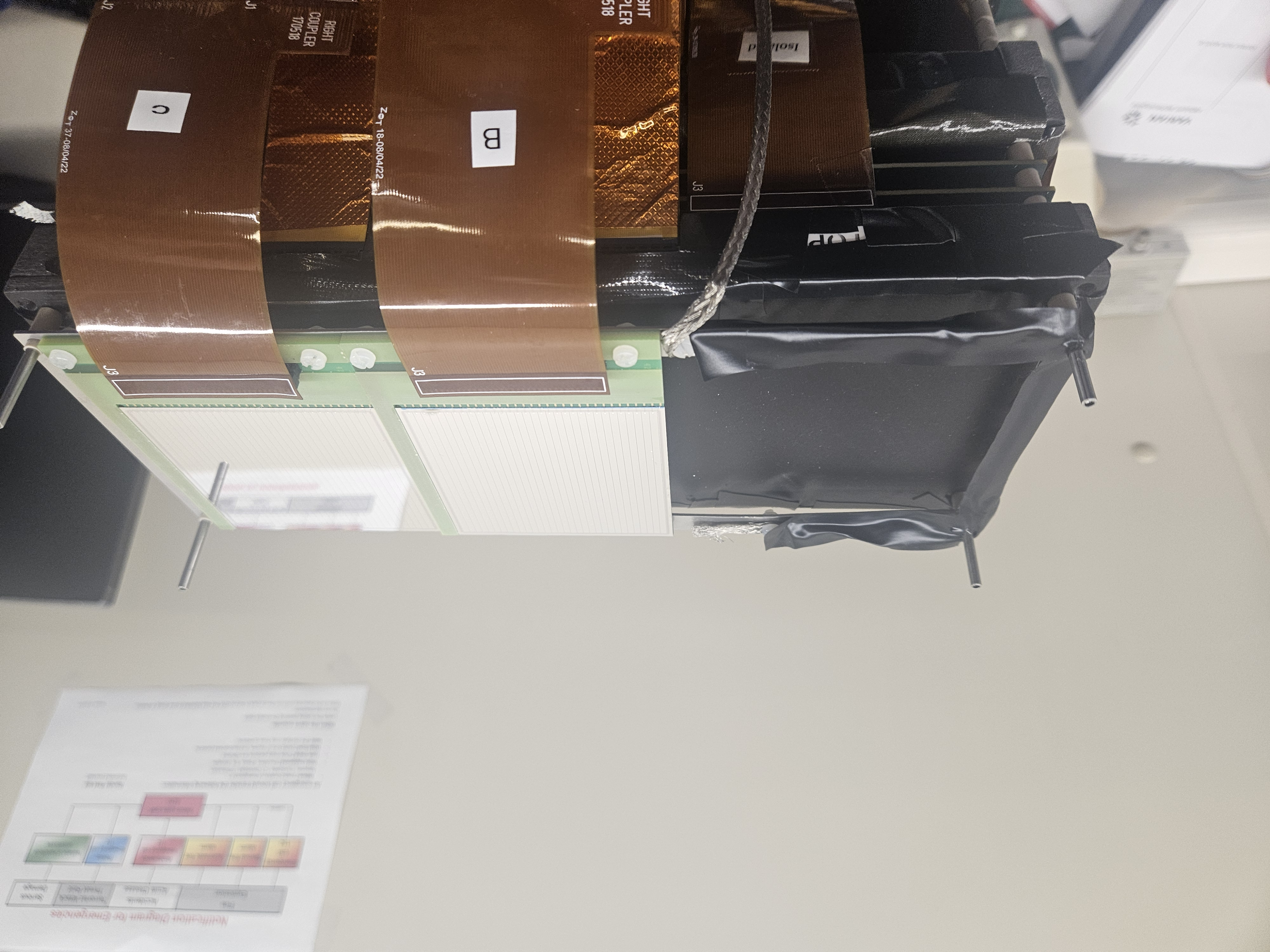
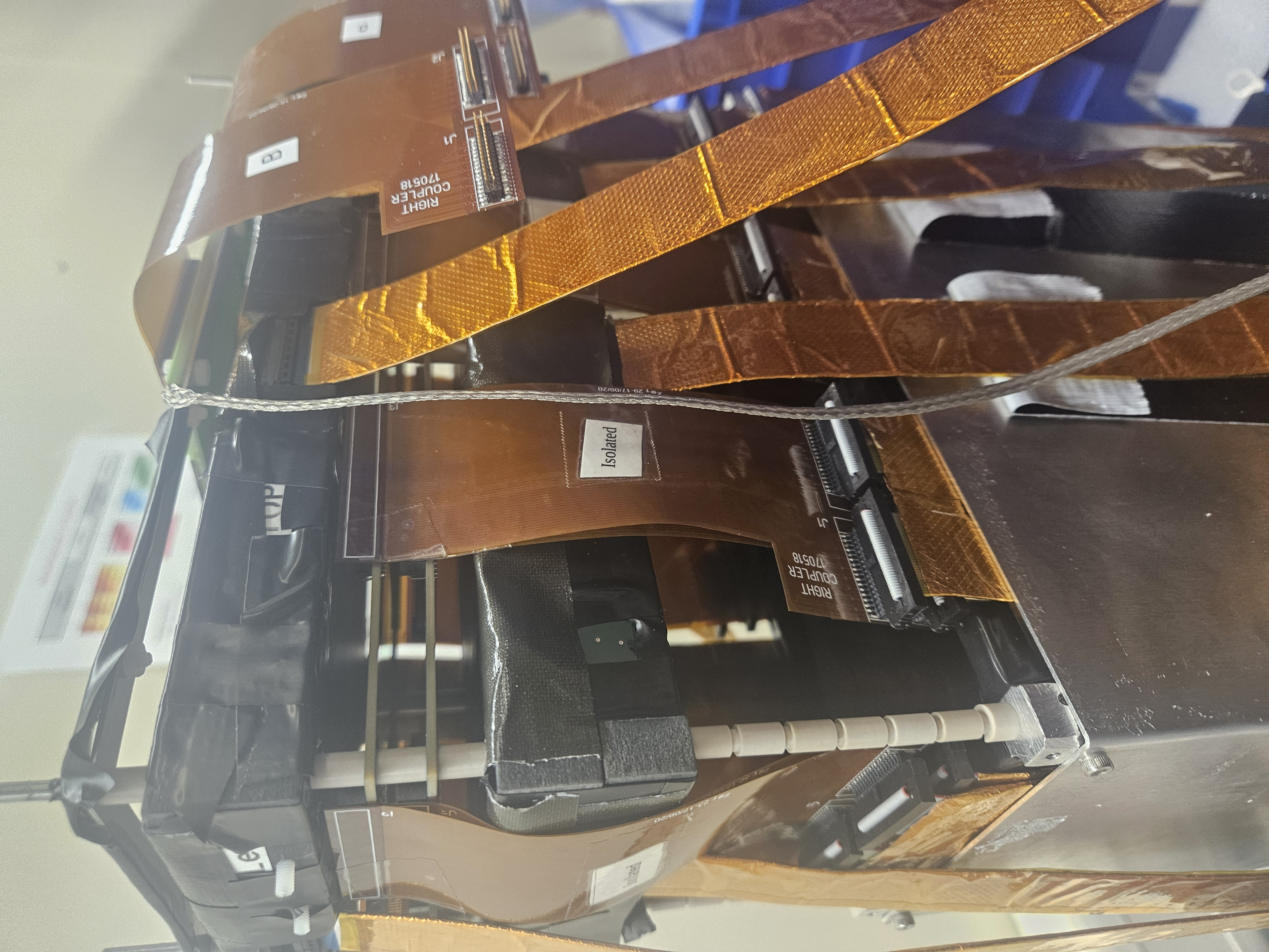
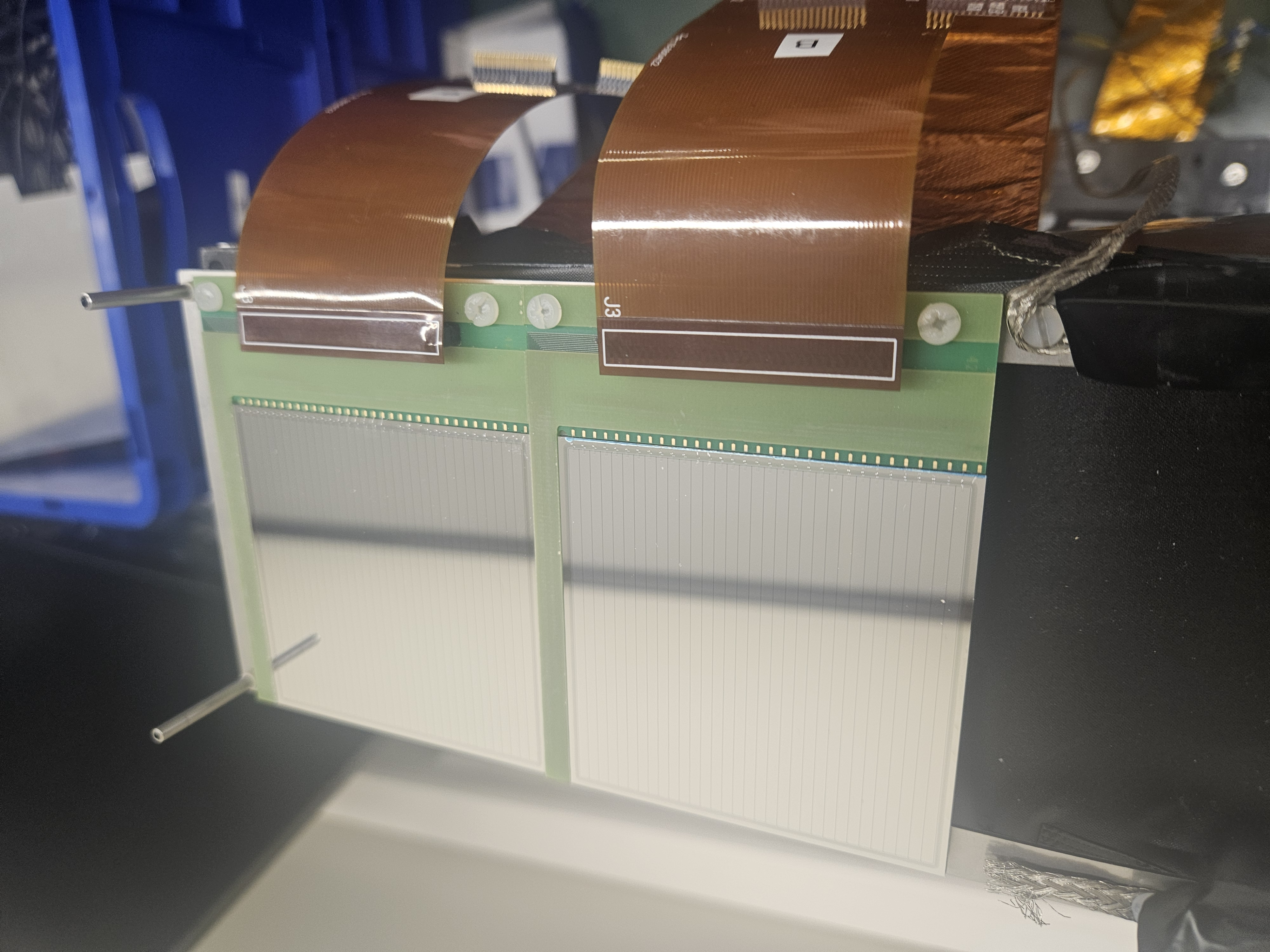
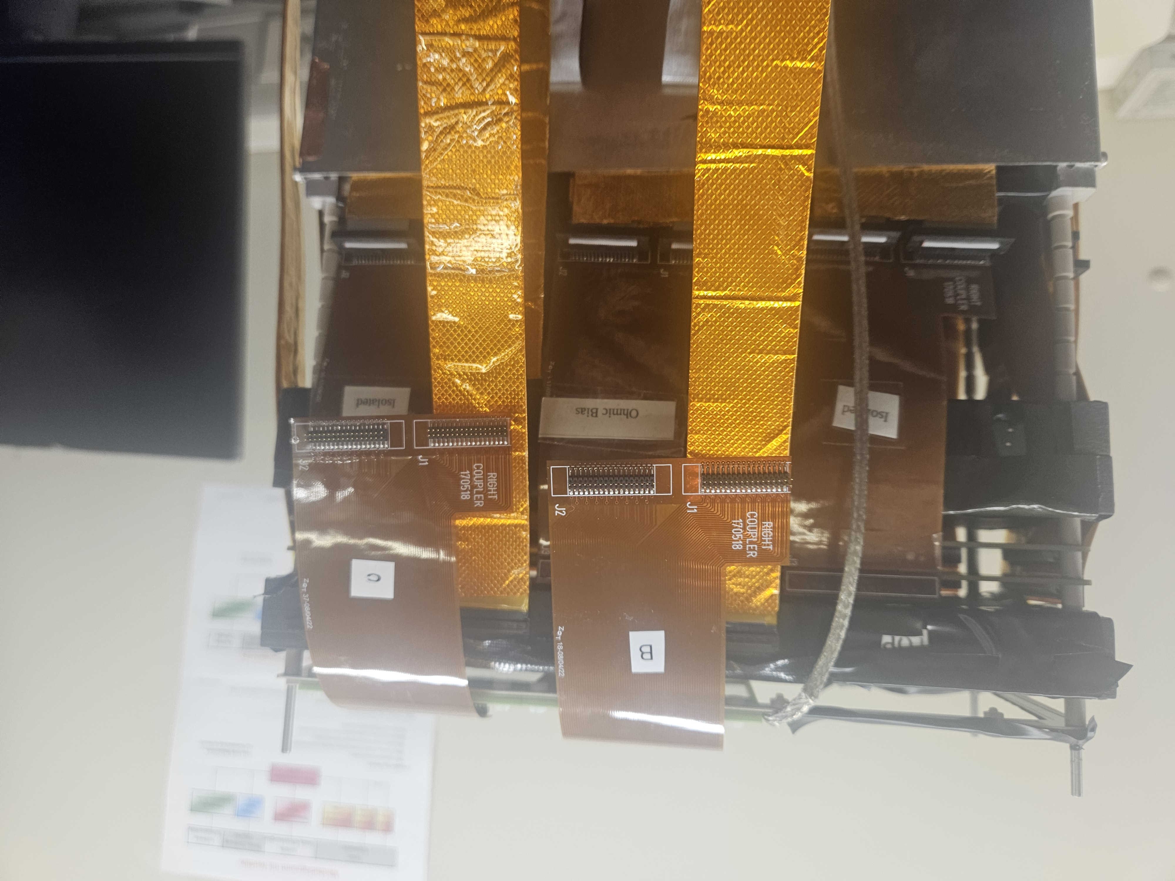
AIDA and the Snout have been remounted in S4

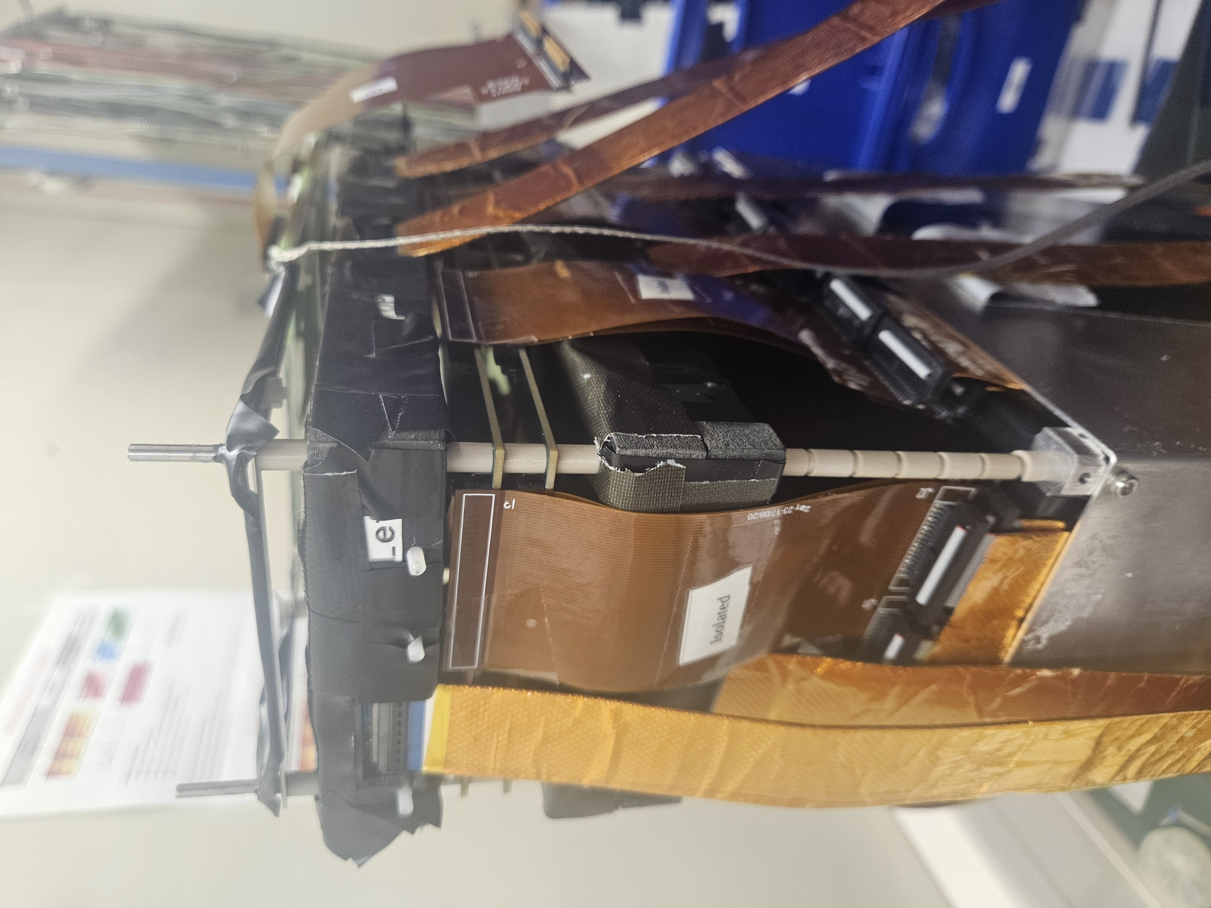
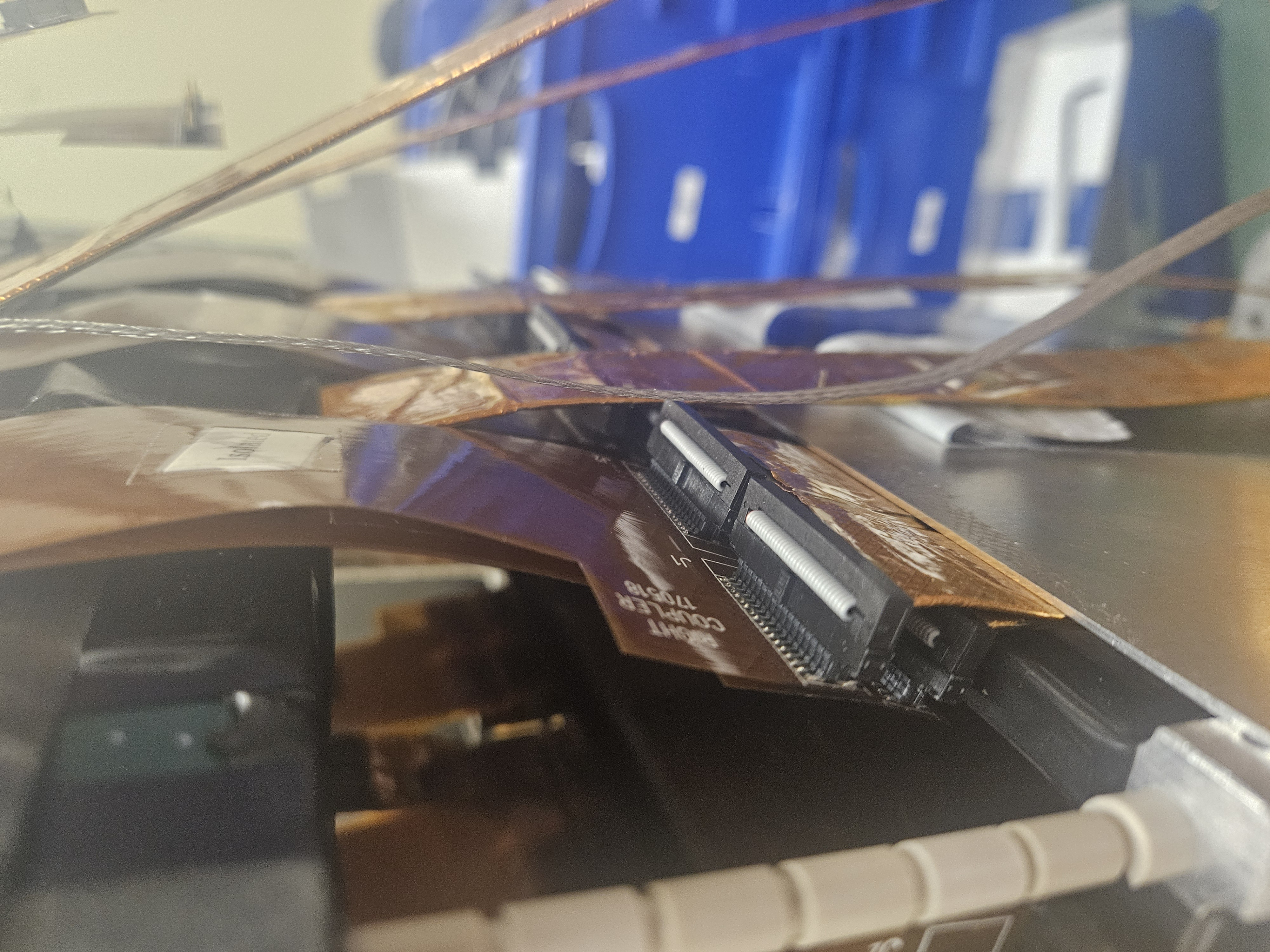
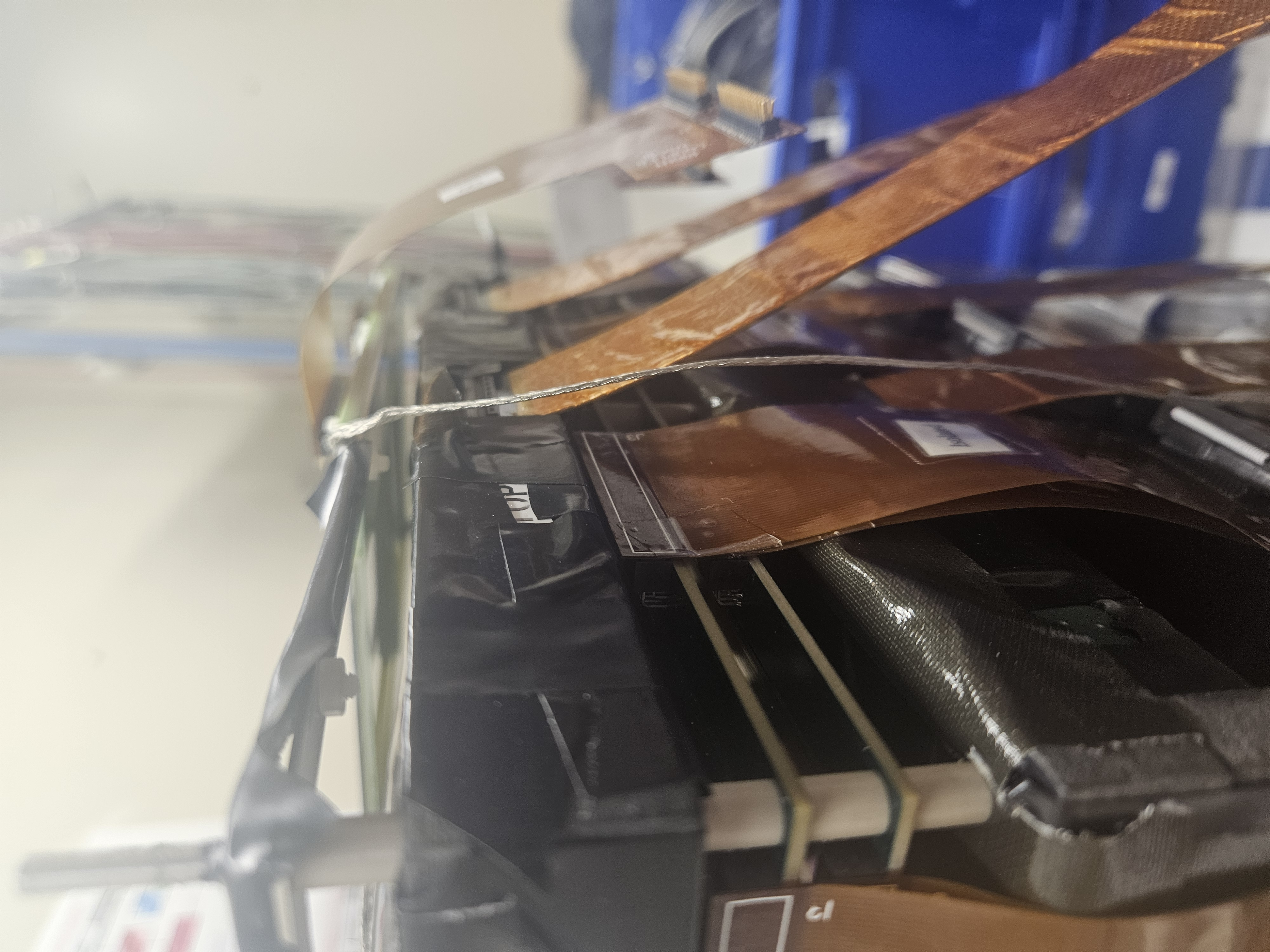
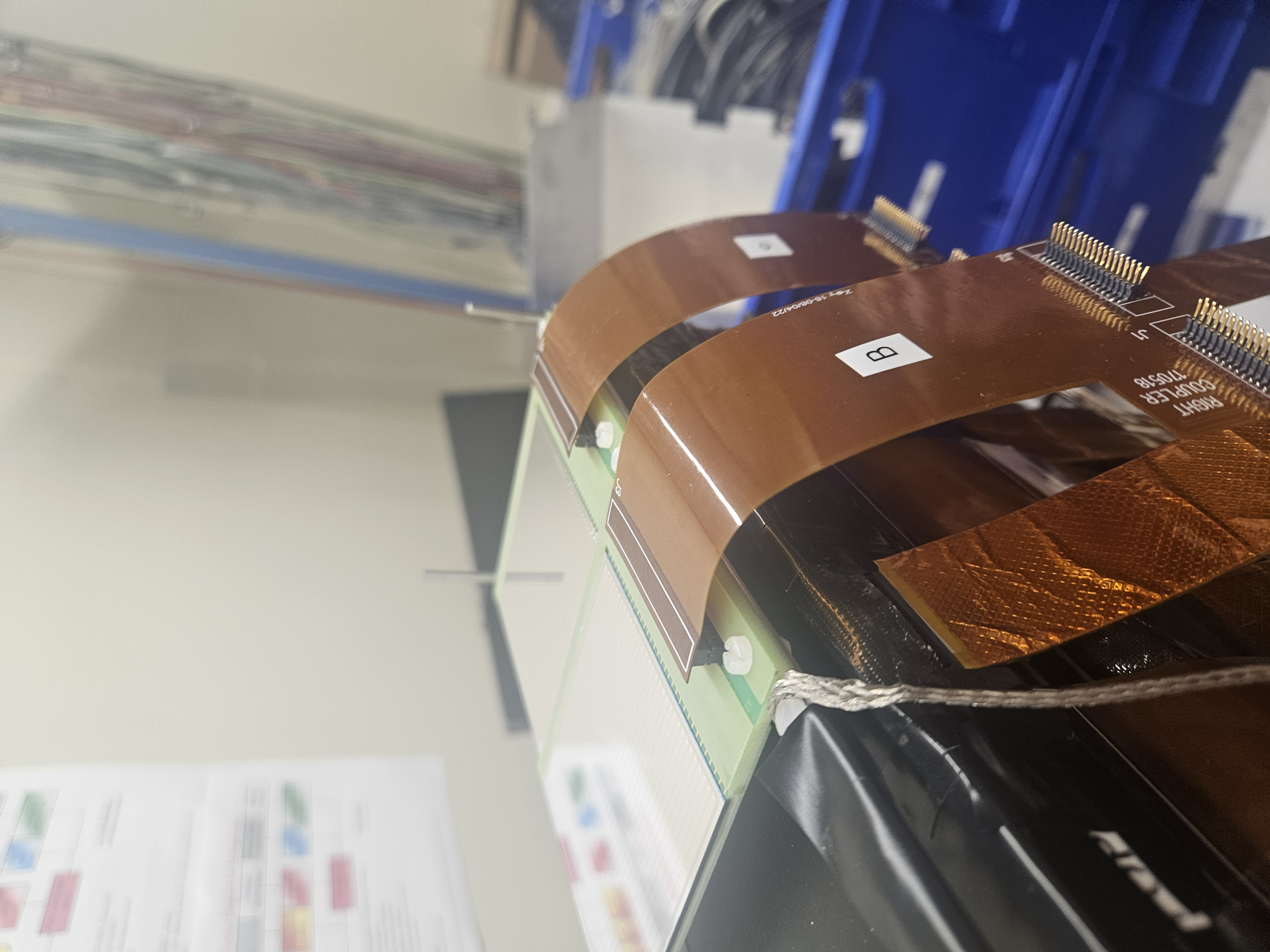
I had a check of the AIDA connectors and all looked good, the kapton PCB connectors were sitting comfortably above the interstage and I saw no stressed/loose connectors.
Multimeter showed no continuity between snout or inter-stage and AIDA ground

We put a single layer of wide black tape inside the end-cap to improve the light seal and minimise reflections

After mounting the snout I managed to bias both DSSDs to 100 V with no issues. I had to raise the DSSD#1 (Ch0) limit to 40 uA because it rises quite high during ramp up (then settles).

It is very hot in S4 (28 C) and the roof is closed for high-radiation experiments, so I expect it to get hotter. DSSD leakage currents were similar to before (20 and 15 uA)

There is also the new Temp and Humidity monitor, which you can view on AnyDesk at 192.168.11.119 (I think), there is a firefox window open already |
| Attachment 1: 20240522_153750.jpg
|
|
| Attachment 2: 20240522_153752.jpg
|
|
| Attachment 3: 20240522_153755.jpg
|
|
| Attachment 4: 20240522_153757.jpg
|
|
| Attachment 5: 20240522_153805.jpg
|
|
| Attachment 6: 20240522_153807.jpg
|
|
| Attachment 7: 20240522_153809.jpg
|
|
| Attachment 8: 20240522_153810.jpg
|
|
| Attachment 9: 20240522_153819.jpg
|
|
|
30
|
Thu Mar 21 15:45:48 2019 |
NH, AS, SA, MP | Snout Mounting & DSSD Bias |
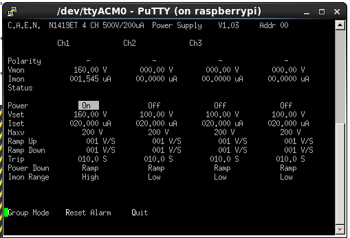
The AIDA snout (with single DSSD and plastic) has been mounted in S4 cave again. DSSD was connected to the outer 4 FEEs again.
-160 V Bias applied and DSSD holds voltage with leakage current of around 1.3 uA (was dropping as only biased briefly)
Bias off and FEEs offline again now as day nearly done. MBS testing will be performed shortly, as well as resolution checks. |
| Attachment 1: LeakageBias.png
|
|
|
544
|
Thu Mar 21 15:41:49 2024 |
NH, AM, MP, CC | Thu Mar 21 |
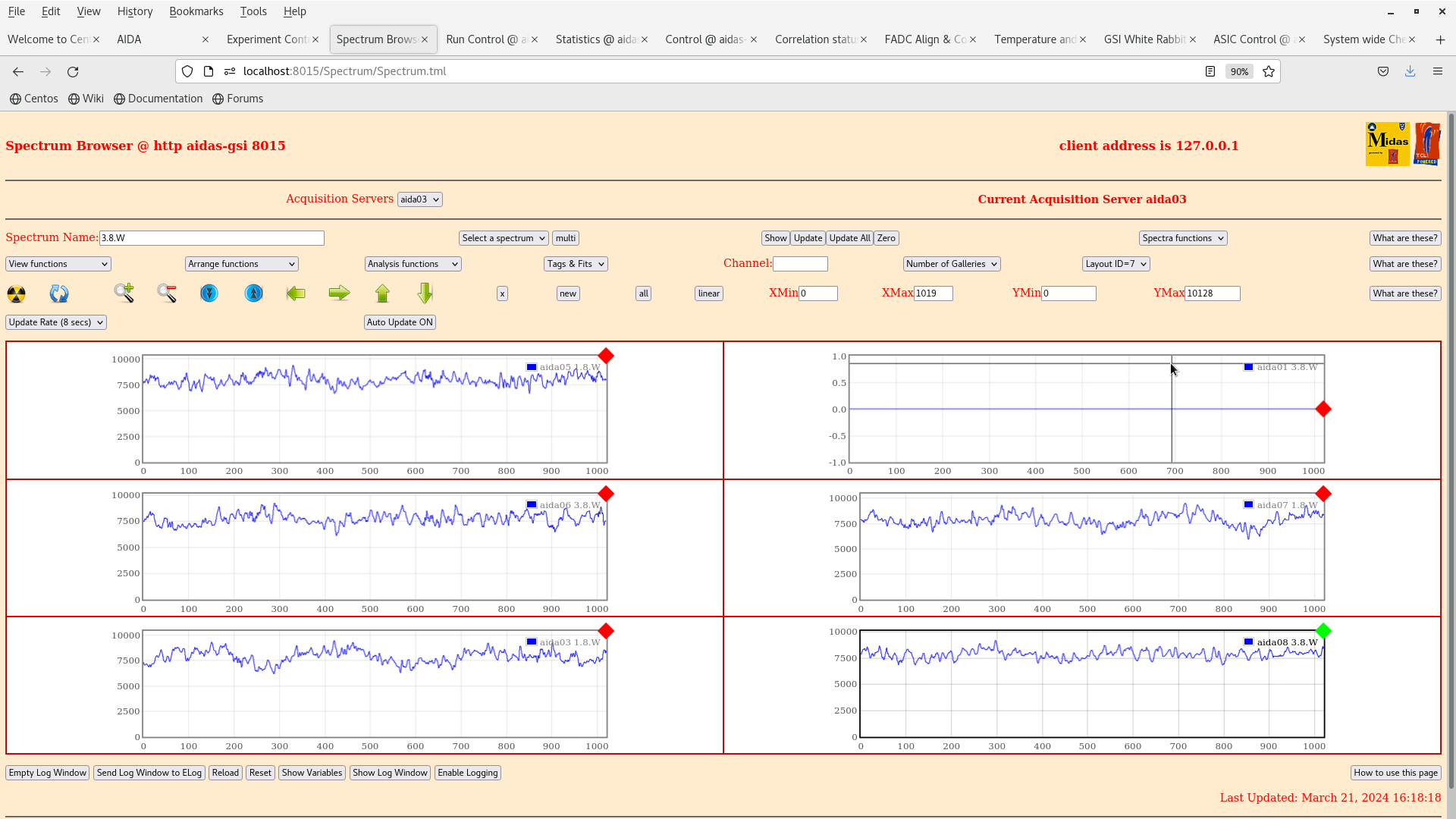
Fig 1-3: Noise situation at real thresholds (0xa p+n, 0xf n+n)

Fig 4-6: After AM and MP turn off Mesytec Preamps

No difference |
| Attachment 1: Screenshot_from_2024-03-21_16-17-59.png
|

|
| Attachment 2: Screenshot_from_2024-03-21_16-18-25.png
|
|
| Attachment 3: Screenshot_from_2024-03-21_16-18-42.png
|

|
| Attachment 4: Screenshot_from_2024-03-21_16-39-12.png
|

|
| Attachment 5: Screenshot_from_2024-03-21_16-39-26.png
|

|
| Attachment 6: Screenshot_from_2024-03-21_16-39-39.png
|

|
|
546
|
Fri Mar 22 08:22:43 2024 |
NH, AM, MP, CC | Thu Mar 21 |
> Fig 1-3: Noise situation at real thresholds (0xa p+n, 0xf n+n)
>
> Fig 4-6: After AM and MP turn off Mesytec Preamps
>
> No difference

I think there is a difference in the 1.8.W spectra - the 100kHz ripple is reduced significantly when the Mesytec preamps are switched off. |
|
47
|
Wed Apr 10 12:33:58 2019 |
NH VP | AIDA Firmware Update |
All AIDA modules have been updated to a new firmware 0xd330701 which should fix the merger issues.
A new GSI WR timestamp page has been added to MIDAS - the SYNC rollover is suggested to be 0xe for now.
(VP is working on lowering the rate of WR SYNC infowords)
Tested yesterday and Merger no longer reported major timestamp issues
n.b. aida11 and aida12 didn't update properly until today, this may have caused a few.
MBS relay is currently not functioning (data is confusing) but this is under investigation by VP ASAP.
|
| Attachment 1: 20191004-FeeTemps.png
|

|
| Attachment 2: 20191004-GSIWR.png
|

|