| ID |
Date |
Author |
Subject |
|
656
|
Sun Jun 11 16:04:12 2017 |
DK | Monday 12 June 0:00 ~ 8:00 |
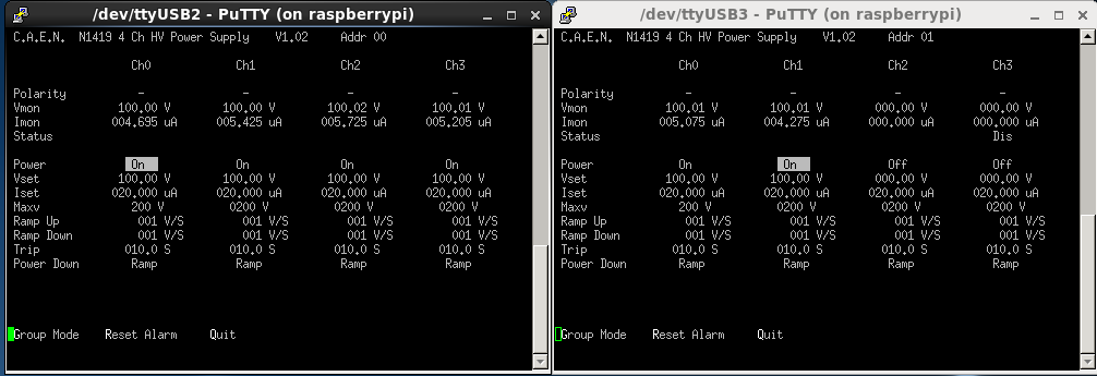
0:04    Biases and leak currents shown as attachment #1, 12JunBias1.png
        System-wide checks: nnaida13 fails ADC calib, all others okay
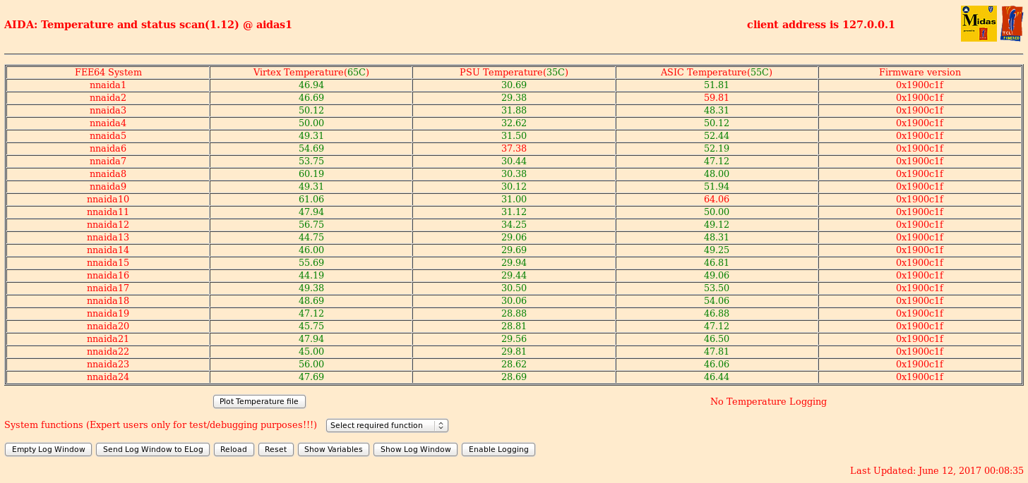
        Temperatures shown as attachment #2, 12JunTemp1.png
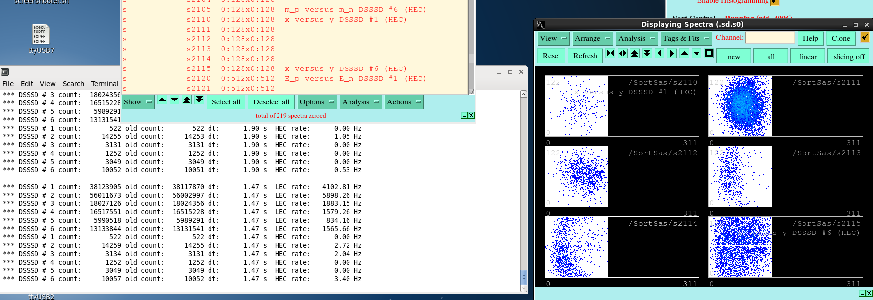
        Implants are 20 to 40 cps, mostly in SSD2 and SSD6 see attachment #3 12JunImplant1.png
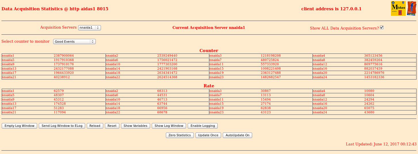
        Statistics shown attachment #4, 12JunStats1.png
        Analysis shown as R9_175.txt attachment #5


00:17   No implants in AIDA nor proper evt. numbers in BRIKEN R9_177, expect beam is down
        Operators call, RF dropped of IRC

00:23   Problem of another RF.

00:24   Beam is back R9_179 for AIDA

00:36   AIDA R9_182 at run close.

00:39   AIDA R9_183, BRIKEN 141, run BigRIPS 4031

00:50   We stop the beam to adjust degraders in F11.  AIDA R9_186
        BRIKEN and BigRIPS runs stopped

00:54   Removed 1.0 mm Al, added 0.5 mm (net is subtracting 0.5 mm Al)
        R9_187 AIDA run, BRIKEN #142, BigRIPS #4032

01:34   AIDA R9_198 at changeover

01:35   Same AIDA run R9_198, BRIKEN #143, BigRIPS #4033
        System wide checks okay (except ADC calib on nnaida13)

02:34   R9_214 at changeover.

2:36    R9_215 with new runs BRIKEN 144 and BigRIPS 4034.
        More implants are now seen in SSD3 rather than SSD2.  Zeroed MIDAS histos, so updated later with stats.
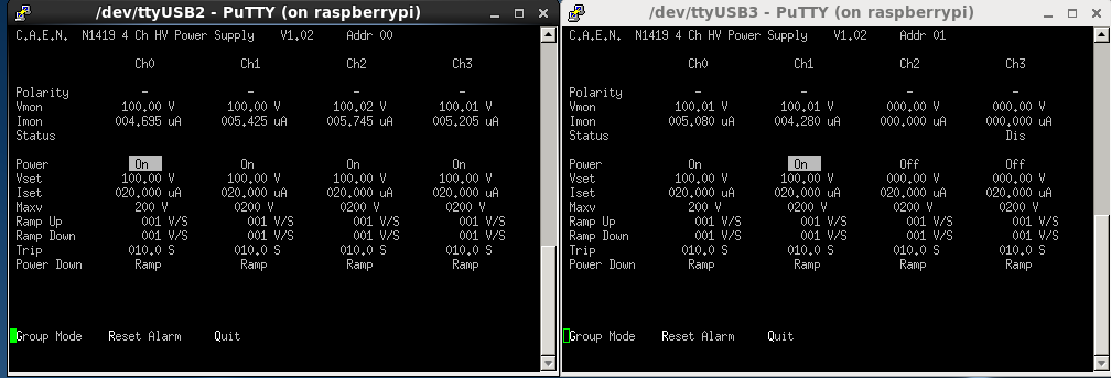
        Biases as attachment #6, 12JunBiases2.png

02:45  Beam stopped R9_217.  Beam stripper has a problem.

02:48  Beam is back, R9_220

03:12  R9_224 operators call, beam is stopped from stripper foil issue

03:18  Beam is back, AIDA run R9_226

03:34  R9_230 at changeover
       System wide checks all okay, except nnaida13 ADC calib as above.

03:35  The end of R9_230 corresponds with BRIKEN 145 and BigRIPS 4034.

03:51  Operators call, beam looks stopped.  R9_235 at AIDA.  Change stripper foil

03:57  R9_236 when beam returns.

04:35  We noticed beam is gone.  R9_246 for AIDA.

04:36  Beam comes back.  R9_247 BRIKEN 146 and BigRIPS 4035
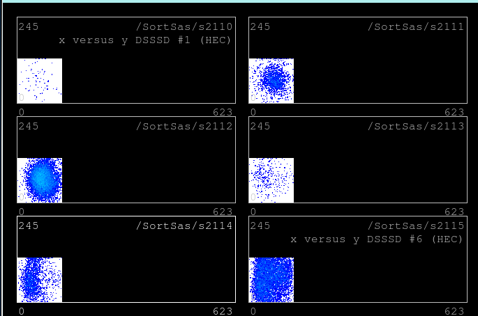
       Attachment #7 12JunImplant2.png shows implantation profile, confirming SSD 3 is the main one with new
degrader setting
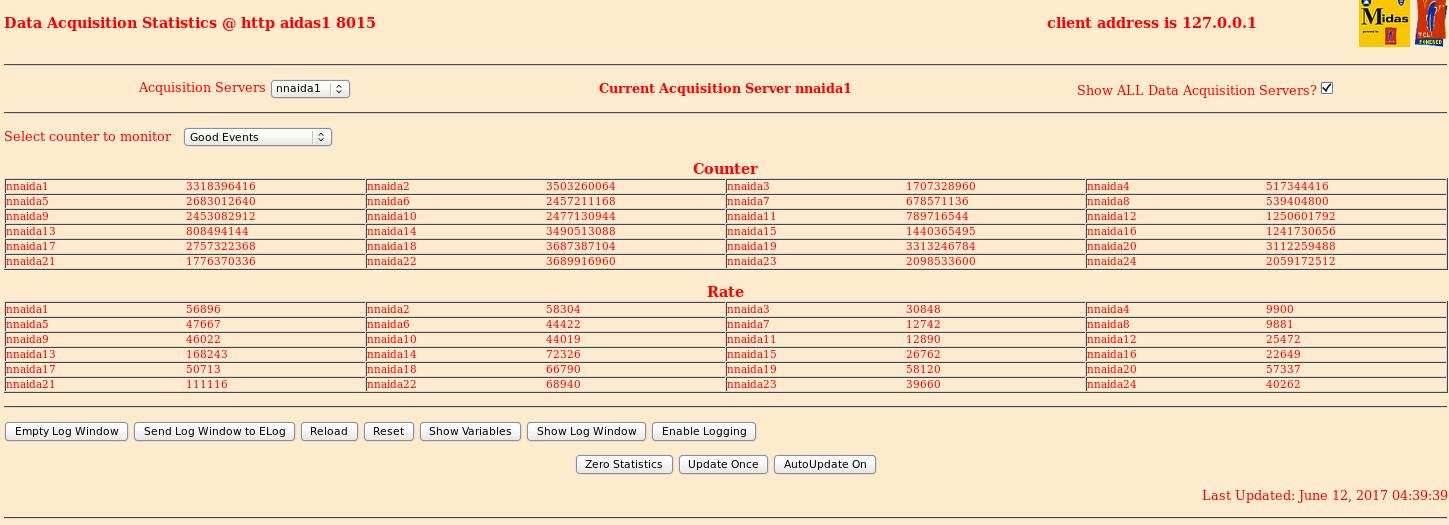
       Statistics shown as attachment #8, 12JunStats2.png
       Analysis shown as attachment #9, R9_244.txt
         No ts timewarps, no MBS timewarps, deadtime on nnaida13,21 nearly 1%, most others small.

05:20  Noticed /data10 only has ~250 GB left, so we should do something to resolve it.
       First thing is, not much compression is done recently.  So I begin to compress /TapeData/RIBF128/R7* with
nice 10
       However, compression at this rate will take much too long so it looks like something should be removed.
       Confirmed that RIBF127R1 data file names and sizes are the same between /TapeData and the new external HDD
at /ntfs

05:33  AIDA R9_262, BRIKEN 147, BigRIPS 4036

06:34  AIDA R9_279 at run change

06:36  BRIKEN run 148, BigRIPS 4037
       System-wide checks passed, except nnaida13 ADC calib still fails.

06:54  R9_284 beam is stopped.

6:59   Beam is back.

07:33  R9_295 at start of BRIKEN 149, BigRIPS 4037

07:36  No syncs are seen at BRIKEN (but they were seen at the start of other runs)
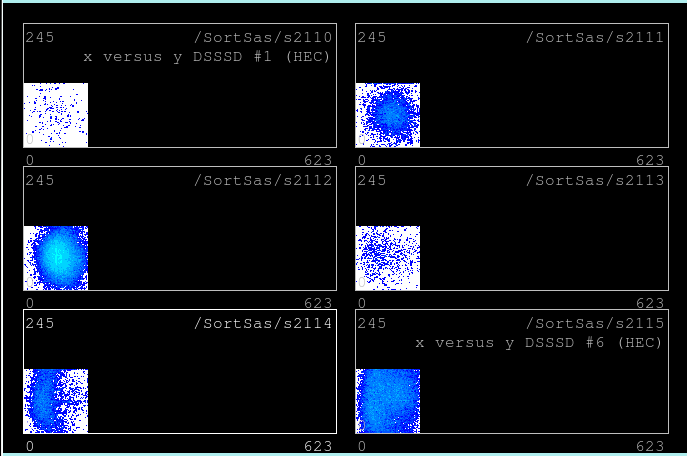
       Implant profiles shown as Attachment #10, 12JunImplants3.png
       Several resets or new runs on BRIKEN / BigRIPS are done to troubleshoot

07:48  AIDA passes all system checks (besides the nnaida13 ADC calib)
       It seems (part of) the issue is triggers from BigRIPS.

08:04  BigRIPS scalers show events are presented, but no triggers are accepted.
       Some part of the DAQ is vetoing the events basically.

08:11  Baba san came on shift.  Issue was ccnet03 crashed.  We reset the Camac crate and reinitialized, DAQ comes back
AIDA R9_306, BRIKEN #152, BigRIPS # 4041 |
| Attachment 1: 12JunBias1.png
|
|
| Attachment 2: 12JunTemp1.png
|
|
| Attachment 3: 12JunImplant1.png
|
|
| Attachment 4: 12JunStats1.png
|
|
| Attachment 5: R9_175.txt
|
*** TDR format 3.3.0 analyser - TD - June 2017
*** MBS information: block: 3650 ptr: 7 data: 0x868200E8 module: 6 information type: 8 information field: 0x000200E8 ts: 0x03B7D6EDA22B OLD ts: 0x03B7D6EDA22B MBS 0x:00E80000D2E6 OLD MBS 0x:00E8005255EE
*** MBS information: block: 8210 ptr: 9 data: 0x868200E8 module: 6 information type: 8 information field: 0x000200E8 ts: 0x03B88A38D84B OLD ts: 0x03B88A38D84B MBS 0x:00E82D250000 OLD MBS 0x:00E82D251E47
*** MBS information: block: 11654 ptr: 7 data: 0x868200E8 module: 6 information type: 8 information field: 0x000200E8 ts: 0x03B913407867 OLD ts: 0x03B913407867 MBS 0x:00E800008875 OLD MBS 0x:00E84F671D8C
*** MBS information: block: 21709 ptr: 7 data: 0x868200E8 module: 6 information type: 8 information field: 0x000200E8 ts: 0x03BAAC9D507F OLD ts: 0x03BAAC9D507F MBS 0x:00E80000BE7B OLD MBS 0x:00E8B5BAC5FE
*** MBS information: block: 21754 ptr: 7 data: 0x868200E8 module: 6 information type: 8 information field: 0x000200E8 ts: 0x03BAAE69DB73 OLD ts: 0x03BAAE69DB73 MBS 0x:00E80000E138 OLD MBS 0x:00E8B630FB6A
*** MBS information: block: 21852 ptr: 9 data: 0x868200E8 module: 6 information type: 8 information field: 0x000200E8 ts: 0x03BAB296062F OLD ts: 0x03BAB296062F MBS 0x:00E8B73C0000 OLD MBS 0x:00E8B73C667D
*** ERROR: READ I/O error: 5002
blocks: 32000
ADC data format: 256845838 ( 1184603.2 Hz)
Other data format: 4242162 ( 19565.3 Hz)
Sample trace data format: 0 ( 0.0 Hz)
Undefined format: 0 ( 0.0 Hz)
Other data format type: PAUSE: 88 ( 0.4 Hz)
RESUME: 88 ( 0.4 Hz)
SYNC100: 1984006 ( 9150.5 Hz)
FEE64 disc: 2189787 ( 10099.6 Hz)
MBS info: 68193 ( 314.5 Hz)
Other info: 0 ( 0.0 Hz)
ADC data range bit set: 123157 ( 568.0 Hz)
Timewarps: ADC: 0 ( 0.0 Hz)
PAUSE: 0 ( 0.0 Hz)
RESUME: 0 ( 0.0 Hz)
SYNC100: 0 ( 0.0 Hz)
FEE64 disc: 0 ( 0.0 Hz)
MBS info: 0 ( 0.0 Hz)
Undefined: 0 ( 0.0 Hz)
Sample trace: 0 ( 0.0 Hz)
*** Timestamp elapsed time: 216.820 s
FEE elapsed dead time(s) elapsed idle time(s)
1 0.036 0.000
2 0.122 0.000
3 0.000 0.000
4 0.000 0.000
5 0.237 0.000
6 0.009 0.000
7 0.000 0.000
8 0.000 0.000
9 0.007 0.000
10 0.023 0.000
11 0.000 0.000
12 0.000 0.000
13 0.473 0.404
14 0.190 0.000
15 0.000 0.000
16 0.000 0.000
17 0.015 0.000
18 0.122 0.000
19 0.150 0.000
20 0.192 0.000
21 0.492 0.516
22 0.088 0.000
23 0.000 0.000
24 0.002 0.000
25 0.000 0.000
26 0.000 0.000
27 0.000 0.000
28 0.000 0.000
29 0.000 0.000
30 0.000 0.000
31 0.000 0.000
32 0.000 0.000
*** Statistics
FEE ADC Data Other Data Sample Undefined Pause Resume SYNC100 Disc MBS Other HEC Data
0 0 0 0 0 0 0 0 0 0 0 0
1 13503596 189538 0 0 2 2 82688 106846 0 0 9030
2 14745926 231651 0 0 5 5 82654 148987 0 0 8663
3 6530190 110062 0 0 0 0 82702 27360 0 0 1932
4 2003109 119133 0 0 0 0 82702 36431 0 0 2789
5 10153436 142365 0 0 21 21 82606 59717 0 0 2946
6 9353593 214643 0 0 2 2 82694 63752 68193 0 3151
7 2577795 118419 0 0 0 0 82701 35718 0 0 3023
8 2030076 114078 0 0 0 0 82701 31377 0 0 2711
9 9769095 204445 0 0 2 2 82699 121742 0 0 5416
10 9893539 228916 0 0 5 5 82698 146208 0 0 5337
11 3110696 117791 0 0 0 0 82700 35091 0 0 2776
12 4932447 128881 0 0 0 0 82704 46177 0 0 3374
13 37417420 138975 0 0 8 8 82521 56438 0 0 3088
14 13501224 158859 0 0 7 7 82628 76217 0 0 4245
15 5478247 128883 0 0 0 0 82693 46190 0 0 3856
16 4837434 116609 0 0 0 0 82702 33907 0 0 3082
17 10744191 180971 0 0 2 2 82698 98269 0 0 3645
18 14223118 173549 0 0 6 6 82656 90881 0 0 3039
19 13438001 175749 0 0 7 7 82647 93088 0 0 6971
20 12875331 198817 0 0 7 7 82633 116170 0 0 7868
21 24186668 307473 0 0 9 9 82502 224953 0 0 11023
22 14629552 412330 0 0 4 4 82668 329654 0 0 10797
23 8458789 173838 0 0 0 0 82702 91136 0 0 6894
24 8452365 156187 0 0 1 1 82707 73478 0 0 7501
25 0 0 0 0 0 0 0 0 0 0 0
26 0 0 0 0 0 0 0 0 0 0 0
27 0 0 0 0 0 0 0 0 0 0 0
28 0 0 0 0 0 0 0 0 0 0 0
29 0 0 0 0 0 0 0 0 0 0 0
30 0 0 0 0 0 0 0 0 0 0 0
31 0 0 0 0 0 0 0 0 0 0 0
32 0 0 0 0 0 0 0 0 0 0 0
*** Timewarps
FEE ADC Pause Resume SYNC100 Disc MBS Undefined Samples
0 0 0 0 0 0 0 0 0
1 0 0 0 0 0 0 0 0
2 0 0 0 0 0 0 0 0
3 0 0 0 0 0 0 0 0
4 0 0 0 0 0 0 0 0
5 0 0 0 0 0 0 0 0
6 0 0 0 0 0 0 0 0
7 0 0 0 0 0 0 0 0
8 0 0 0 0 0 0 0 0
9 0 0 0 0 0 0 0 0
10 0 0 0 0 0 0 0 0
11 0 0 0 0 0 0 0 0
12 0 0 0 0 0 0 0 0
13 0 0 0 0 0 0 0 0
14 0 0 0 0 0 0 0 0
15 0 0 0 0 0 0 0 0
16 0 0 0 0 0 0 0 0
17 0 0 0 0 0 0 0 0
18 0 0 0 0 0 0 0 0
19 0 0 0 0 0 0 0 0
20 0 0 0 0 0 0 0 0
21 0 0 0 0 0 0 0 0
22 0 0 0 0 0 0 0 0
23 0 0 0 0 0 0 0 0
24 0 0 0 0 0 0 0 0
25 0 0 0 0 0 0 0 0
26 0 0 0 0 0 0 0 0
27 0 0 0 0 0 0 0 0
28 0 0 0 0 0 0 0 0
29 0 0 0 0 0 0 0 0
30 0 0 0 0 0 0 0 0
31 0 0 0 0 0 0 0 0
32 0 0 0 0 0 0 0 0
*** MBS Timewarps
FEE
0 0
1 0
2 0
3 0
4 0
5 0
6 6
7 0
8 0
9 0
10 0
11 0
12 0
13 0
14 0
15 0
16 0
17 0
18 0
19 0
20 0
21 0
22 0
23 0
24 0
25 0
26 0
27 0
28 0
29 0
30 0
31 0
32 0
*** Program elapsed time: 35.784s ( 894.255 blocks/s, 55.891 Mb/s)
|
| Attachment 6: 12JunBias2.png
|
|
| Attachment 7: 12JunImplant2.png
|
|
| Attachment 8: 12JunStats2.png
|
|
| Attachment 9: R9_244.txt
|
*** TDR format 3.3.0 analyser - TD - June 2017
*** MBS information: block: 4269 ptr: 7 data: 0x86820141 module: 6 information type: 8 information field: 0x00020141 ts: 0x051F386A0B7F OLD ts: 0x051F386A0B7F MBS 0x:01410000ED3B OLD MBS 0x:0141D8AE6253
*** MBS information: block: 20181 ptr: 9 data: 0x86820142 module: 6 information type: 8 information field: 0x00020142 ts: 0x0521B8C200C3 OLD ts: 0x0521B8C200C3 MBS 0x:014278C70000 OLD MBS 0x:014278C79B42
*** MBS information: block: 23476 ptr: 7 data: 0x86820142 module: 6 information type: 8 information field: 0x00020142 ts: 0x05223E484B47 OLD ts: 0x05223E484B47 MBS 0x:014200007D2D OLD MBS 0x:01429A254F63
*** MBS information: block: 29611 ptr: 7 data: 0x86820142 module: 6 information type: 8 information field: 0x00020142 ts: 0x052338CA34C3 OLD ts: 0x052338CA34C3 MBS 0x:01420000F78C OLD MBS 0x:0142D8C6A4E6
*** ERROR: READ I/O error: 5002
blocks: 32000
ADC data format: 256490928 ( 1179425.3 Hz)
Other data format: 4597072 ( 21138.8 Hz)
Sample trace data format: 0 ( 0.0 Hz)
Undefined format: 0 ( 0.0 Hz)
Other data format type: PAUSE: 98 ( 0.5 Hz)
RESUME: 98 ( 0.5 Hz)
SYNC100: 1989622 ( 9148.9 Hz)
FEE64 disc: 2535193 ( 11657.6 Hz)
MBS info: 72061 ( 331.4 Hz)
Other info: 0 ( 0.0 Hz)
ADC data range bit set: 152277 ( 700.2 Hz)
Timewarps: ADC: 0 ( 0.0 Hz)
PAUSE: 0 ( 0.0 Hz)
RESUME: 0 ( 0.0 Hz)
SYNC100: 0 ( 0.0 Hz)
FEE64 disc: 0 ( 0.0 Hz)
MBS info: 0 ( 0.0 Hz)
Undefined: 0 ( 0.0 Hz)
Sample trace: 0 ( 0.0 Hz)
*** Timestamp elapsed time: 217.471 s
FEE elapsed dead time(s) elapsed idle time(s)
1 0.082 0.000
2 0.085 0.000
3 0.000 0.000
4 0.000 0.000
5 0.134 0.000
6 0.014 0.000
7 0.000 0.000
8 0.000 0.000
9 0.037 0.000
10 0.008 0.000
11 0.000 0.000
12 0.000 0.000
13 0.937 0.886
14 0.078 0.000
15 0.000 0.000
16 0.000 0.000
17 0.025 0.000
18 0.122 0.000
19 0.213 0.000
20 0.308 0.000
21 0.924 0.967
22 0.018 0.000
23 0.068 0.000
24 0.000 0.000
25 0.000 0.000
26 0.000 0.000
27 0.000 0.000
28 0.000 0.000
29 0.000 0.000
30 0.000 0.000
31 0.000 0.000
32 0.000 0.000
*** Statistics
FEE ADC Data Other Data Sample Undefined Pause Resume SYNC100 Disc MBS Other HEC Data
0 0 0 0 0 0 0 0 0 0 0 0
1 13167786 177701 0 0 5 5 82921 94770 0 0 9717
2 13999920 215424 0 0 4 4 82916 132500 0 0 9819
3 6572094 114056 0 0 0 0 82946 31110 0 0 2345
4 2037247 124786 0 0 0 0 82945 41841 0 0 2983
5 10315892 144198 0 0 12 12 82898 61276 0 0 3111
6 9386945 219804 0 0 3 3 82948 64789 72061 0 3214
7 2648431 124549 0 0 0 0 82948 41601 0 0 3475
8 2076433 116754 0 0 0 0 82949 33805 0 0 3076
9 10087149 348448 0 0 4 4 82939 265501 0 0 8674
10 9696461 197086 0 0 1 1 82947 114137 0 0 5520
11 3164192 118620 0 0 0 0 82948 35672 0 0 2792
12 5356061 160377 0 0 0 0 82947 77430 0 0 7587
13 36291328 139867 0 0 12 12 82593 57250 0 0 3143
14 14842188 478995 0 0 4 4 82923 396064 0 0 9899
15 5976764 161410 0 0 0 0 82954 78456 0 0 8856
16 4885978 119515 0 0 0 0 82954 36561 0 0 3327
17 10814272 203399 0 0 2 2 82939 120456 0 0 4549
18 14266776 177547 0 0 5 5 82896 94641 0 0 3830
19 13236547 187767 0 0 8 8 82870 104881 0 0 7087
20 12550626 205783 0 0 13 13 82836 122921 0 0 8336
21 23354593 279814 0 0 17 17 82596 197184 0 0 13110
22 14483453 223561 0 0 1 1 82937 140622 0 0 11976
23 8629169 185401 0 0 7 7 82924 102463 0 0 7859
24 8650623 172210 0 0 0 0 82948 89262 0 0 7992
25 0 0 0 0 0 0 0 0 0 0 0
26 0 0 0 0 0 0 0 0 0 0 0
27 0 0 0 0 0 0 0 0 0 0 0
28 0 0 0 0 0 0 0 0 0 0 0
29 0 0 0 0 0 0 0 0 0 0 0
30 0 0 0 0 0 0 0 0 0 0 0
31 0 0 0 0 0 0 0 0 0 0 0
32 0 0 0 0 0 0 0 0 0 0 0
*** Timewarps
FEE ADC Pause Resume SYNC100 Disc MBS Undefined Samples
0 0 0 0 0 0 0 0 0
1 0 0 0 0 0 0 0 0
2 0 0 0 0 0 0 0 0
3 0 0 0 0 0 0 0 0
4 0 0 0 0 0 0 0 0
5 0 0 0 0 0 0 0 0
6 0 0 0 0 0 0 0 0
7 0 0 0 0 0 0 0 0
8 0 0 0 0 0 0 0 0
9 0 0 0 0 0 0 0 0
10 0 0 0 0 0 0 0 0
11 0 0 0 0 0 0 0 0
12 0 0 0 0 0 0 0 0
13 0 0 0 0 0 0 0 0
14 0 0 0 0 0 0 0 0
15 0 0 0 0 0 0 0 0
16 0 0 0 0 0 0 0 0
17 0 0 0 0 0 0 0 0
18 0 0 0 0 0 0 0 0
19 0 0 0 0 0 0 0 0
20 0 0 0 0 0 0 0 0
21 0 0 0 0 0 0 0 0
22 0 0 0 0 0 0 0 0
23 0 0 0 0 0 0 0 0
24 0 0 0 0 0 0 0 0
25 0 0 0 0 0 0 0 0
26 0 0 0 0 0 0 0 0
27 0 0 0 0 0 0 0 0
28 0 0 0 0 0 0 0 0
29 0 0 0 0 0 0 0 0
30 0 0 0 0 0 0 0 0
31 0 0 0 0 0 0 0 0
32 0 0 0 0 0 0 0 0
*** MBS Timewarps
FEE
0 0
1 0
2 0
3 0
4 0
5 0
6 4
7 0
8 0
9 0
10 0
11 0
12 0
13 0
14 0
15 0
16 0
17 0
18 0
19 0
20 0
21 0
22 0
23 0
24 0
25 0
26 0
27 0
28 0
29 0
30 0
31 0
32 0
*** Program elapsed time: 19.678s ( 1626.203 blocks/s, 101.638 Mb/s)
|
| Attachment 10: 12JunImplants3.png
|
|
|
852
|
Tue Jun 18 08:03:20 2019 |
DK | Tuesday 18 June 16:00 - 24:00 |
Shift change

16:00
      115 pnA primary, 290 cps implants at F11
      Presently at AIDA R2_616
      DAQ is running smoothly - passes all system checks (except ADC calib of nnaida7)
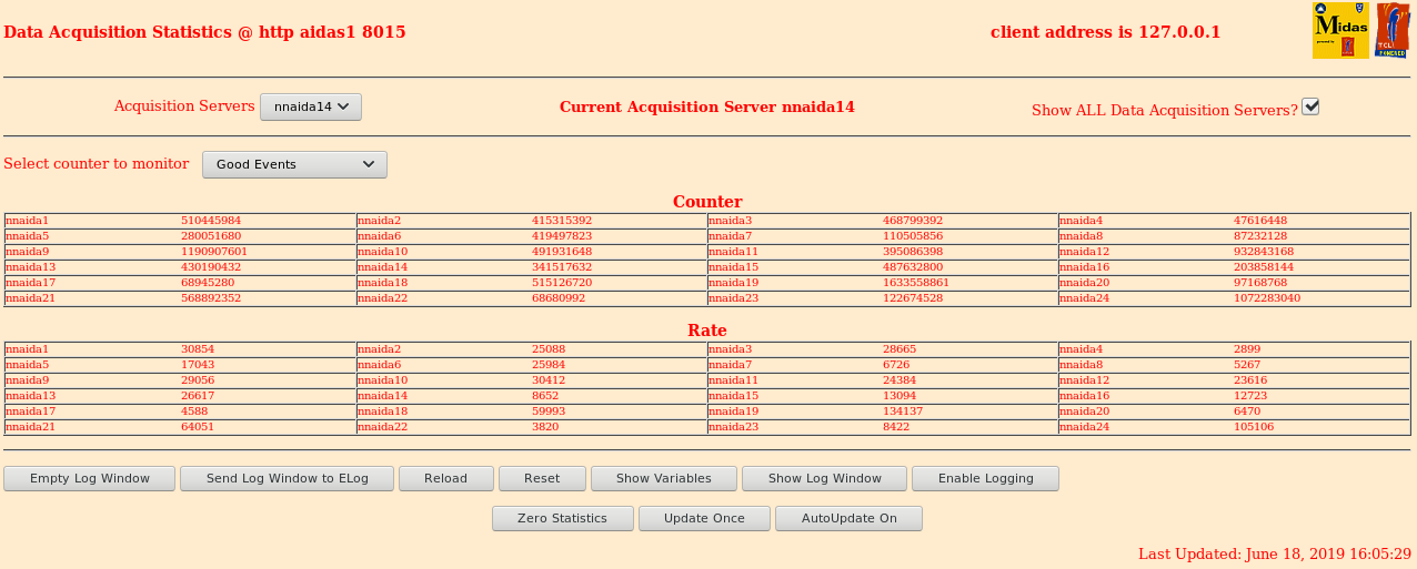
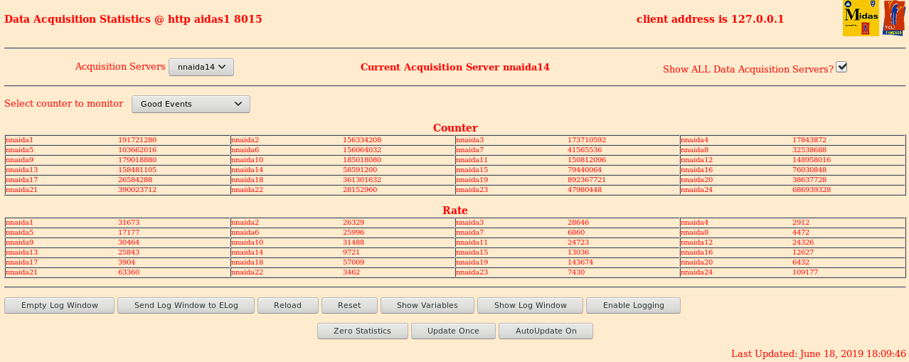
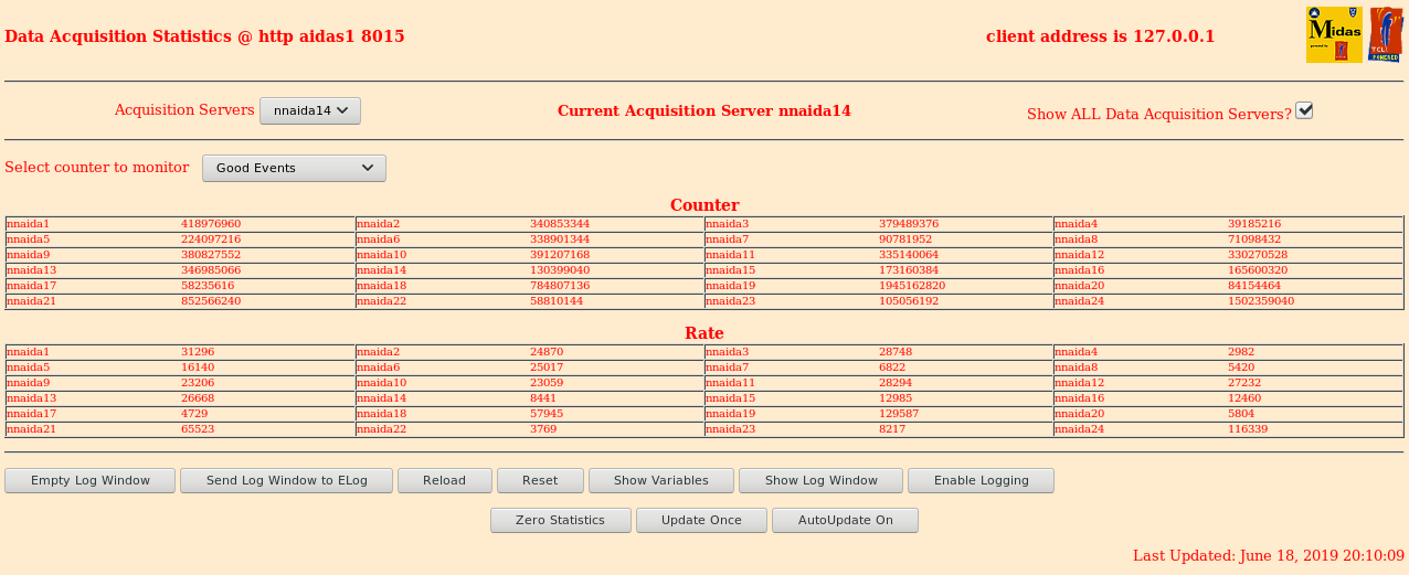
      Stats okay, though nnaida19 and 24 running a bit high (seems consistent w/ previous shift) - attach 1
           (Consistent with lower thresholds, pasted below)

      100Sn setting, 0.3mm Al degrader

      ASIC settings 2019Jun13-08.56.35
      DSSSD#1 slow comparator 0xa -> 0x1d
      DSSSD#2 slow comparator 0xa -> 0x8
      DSSSD#3 slow comparator 0x8 -> 0xa

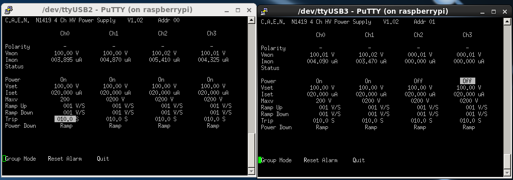
      Biases fine - attach 2
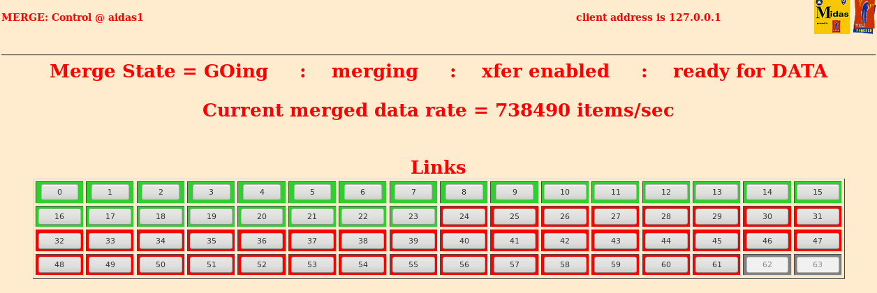
      Merger okay - attach 3
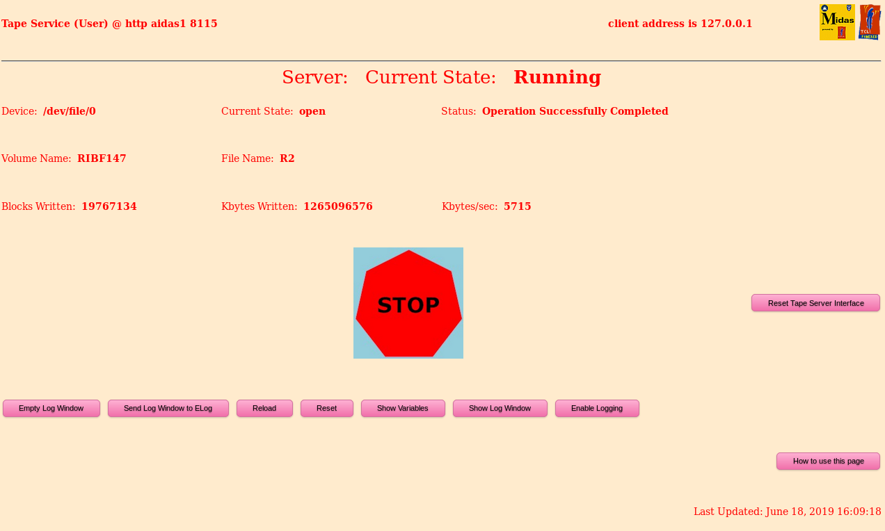
      TapeServer okay - attach 4

16:13 New DTAS run 105
      AIDA R2_618
      BigRIPS is still 2044 as at 15:03

      Temperatures okay - attach 5

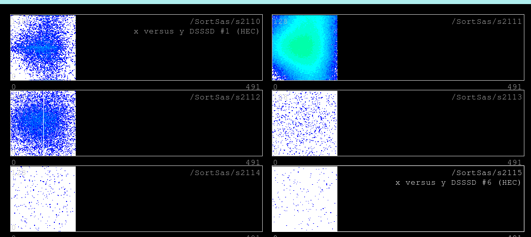
16:20 Implant spectra look good, mainly into DSSSD2 - attach 6

      Spectra saved in ~spectra/specs-2019Jun18-16.24.33

16:30 Zero stats, histograms

17:03 Old runs ending
      AIDA R2_626
      In principle DTAS 106 but it switches quickly to 107
      BigRIPS 2045

17:10 New run DTAS 108, AIDA R2_627

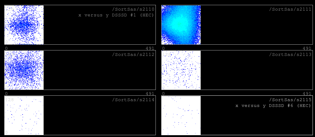
18:09 New implant profile - attach 6
      New stats - attach 7
      Looks okay

19:08 AIDA R2_647, DTAS 110

19:14 AIDA R2_648, DTAS 111, BigRIPS 2046

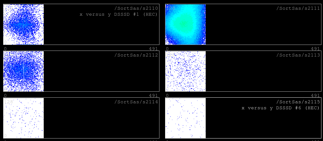
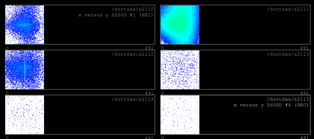
20:08 XY implants - attach 8
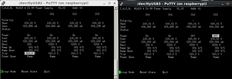
      Bias - attach 9
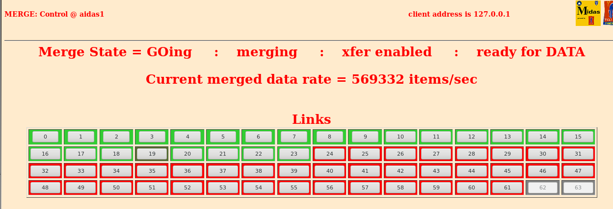
      Merger - attach 10
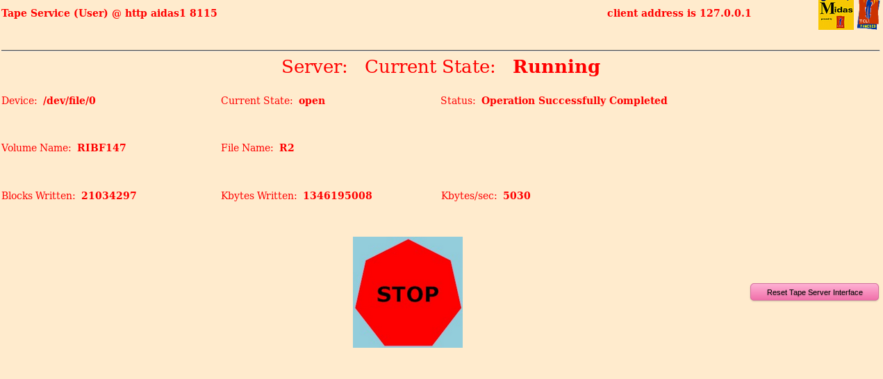
      TapeServer - attach 11
      Stats - attach 12

21:15 New runs: BigRIPS 2047, DTAS 115, AIDA R2_668

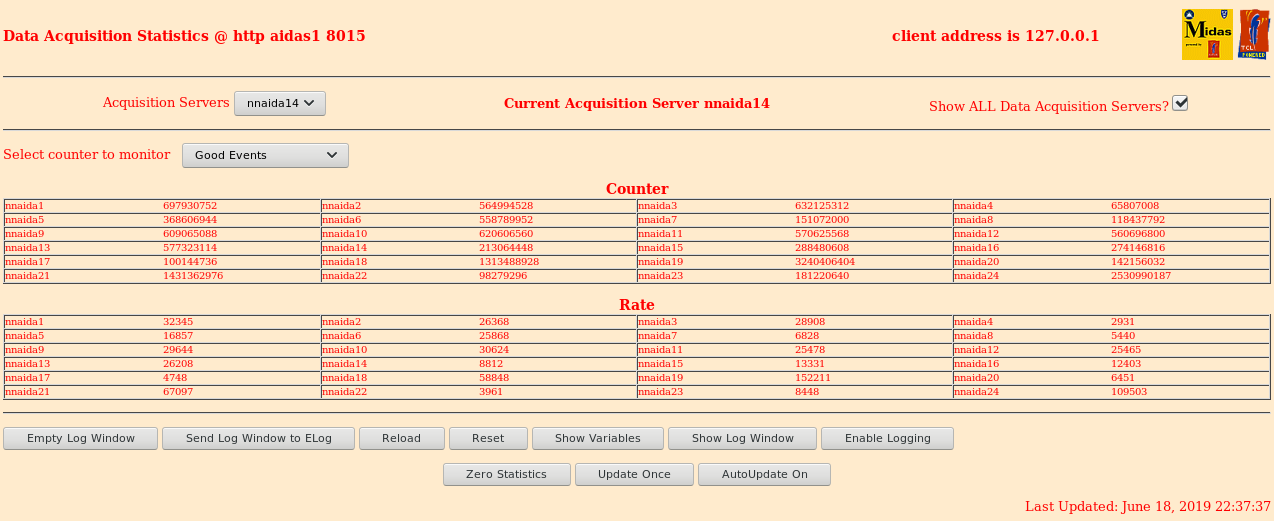
22:37 XY - attached 13; stats - attached 14
      Primary beam at 120 pnA; implants around 250 cps at F11

23:14 DTAS closes the run

23:20 New runs: AIDA R2_688, DTAS 118, BigRIPS 2048 |
| Attachment 1: stats1600.png
|
|
| Attachment 2: bias1600.png
|
|
| Attachment 3: merger1600.png
|
|
| Attachment 4: tapeserver1600.png
|
|
| Attachment 5: temp1600.png
|
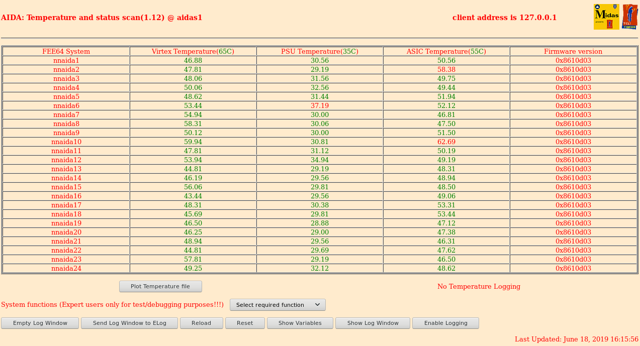
|
| Attachment 6: implants1620.png
|
|
| Attachment 7: xy1809.png
|
|
| Attachment 8: stats1809.png
|
|
| Attachment 9: xy2008.png
|
|
| Attachment 10: bias2008.png
|
|
| Attachment 11: merger2008.png
|
|
| Attachment 12: tapeserver2008.png
|
|
| Attachment 13: stats2008.png
|
|
| Attachment 14: xy2237.png
|
|
| Attachment 15: stats2237.png
|
|
|
30
|
Tue Feb 10 16:01:50 2015 |
Chris Griffin, Alfredo Estrade | High data rate - Pause/Resume |
06/02/15
A look at the data rate at which Pause/Resumes start to cause missing data.
Pulser settings:
Slow comparitor thresholds were altered using the ASIC4 page to artificially increase the data rate in the ASICs.
Default settings for all modules, apart from the changing slow comp threshold.
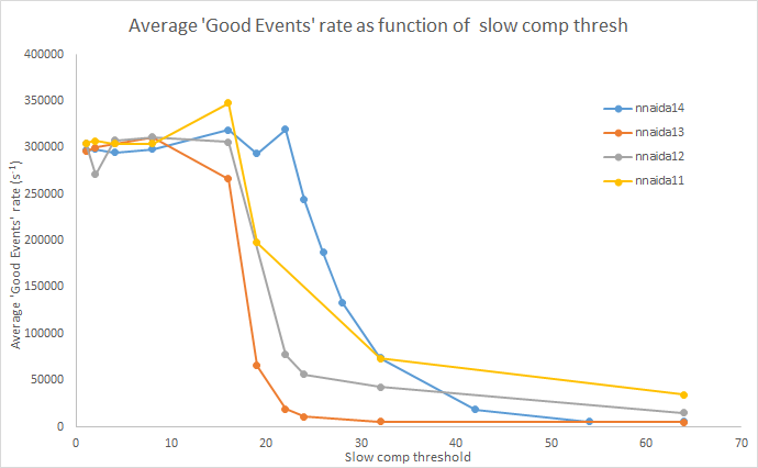
nnaida13+14 both functioning well. nnaida11+12 both have one noisy channel contributing to high data rate.
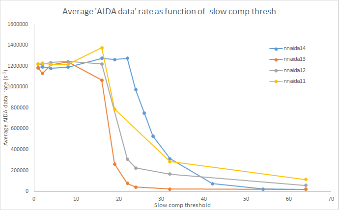
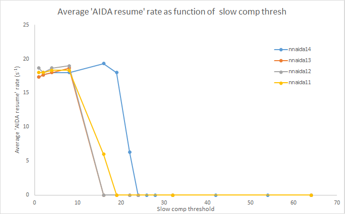
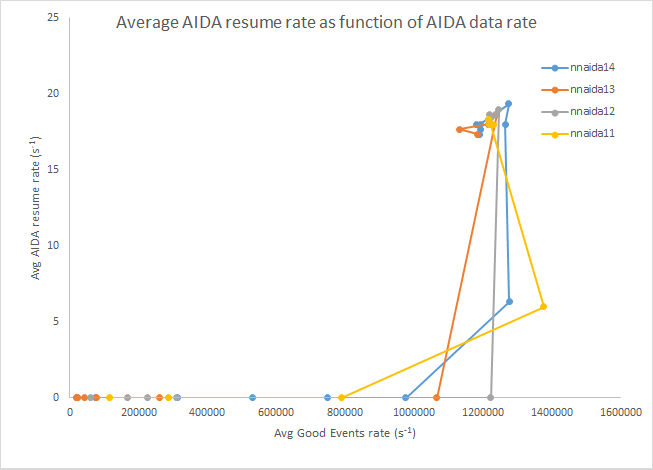
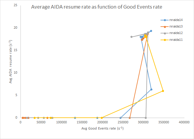
Echoing Alfredo's previous post, using the AIDA Good Events and AIDA Data Rate from the stats page as metrics, I found there to be no Pause/Resume items present in the data up to a Good Events rate of ~250-300 kHz and Data Rate of ~1-1.2 MHz.
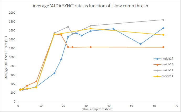
Around this point the data shifts very quickly from containing no Pause/Resume items to having a rate of ~18 Hz, almost as a step function. At this point the Good Events and AIDA data rate sharply reach a maximum rate of 300 kHz and 1.2 MHz respectively. The rate of AIDA SYNC data items drops sharply at this point and decreases slowly with decreasing threshold.
Included are some plots showing this for each of the modules and some summary plots.
Further to the data rate at which the appearance of Pause/Resume items causes significant data loss, I looked at what happens when you break this threshold and then come back down, i.e. do the Pause/Resume items persist?
In short, no. Starting from a threshold of 64 and working down to 1, then taking the slow comparitor threshold back to a level at which no Pause/Resumes were present, the Good Events, AIDA SYNC and AIDA Data rates all went back to their original values within a couple of refreshes of the stats screen (and stayed as such thereafter). |
| Attachment 1: GoodEvts_v_thresh.png
|
|
| Attachment 2: AIDAdata_v_thresh.png
|
|
| Attachment 3: AIDAsync_v_thresh.png
|
|
| Attachment 4: PauseResume_v_thresh.png
|
|
| Attachment 5: ResumeRate_v_AIDAdata.png
|
|
| Attachment 6: ResumeRate_v_GoodEvts.png
|
|
|
14
|
Wed Oct 1 18:37:42 2014 |
Chris Griffin | 01/10/2014 Tests @ DL |
Kept largely the same settings at the entry https://elog.ph.ed.ac.uk/AIDA/4
Same ASIC settings
Emco used to provide HV
HV+ --> nnaida11 & nnaida12 (p+n strips, -ve pulser input)
HV- --> nnaida13 & nnaida14 (n+n strips, +ve pulser input)
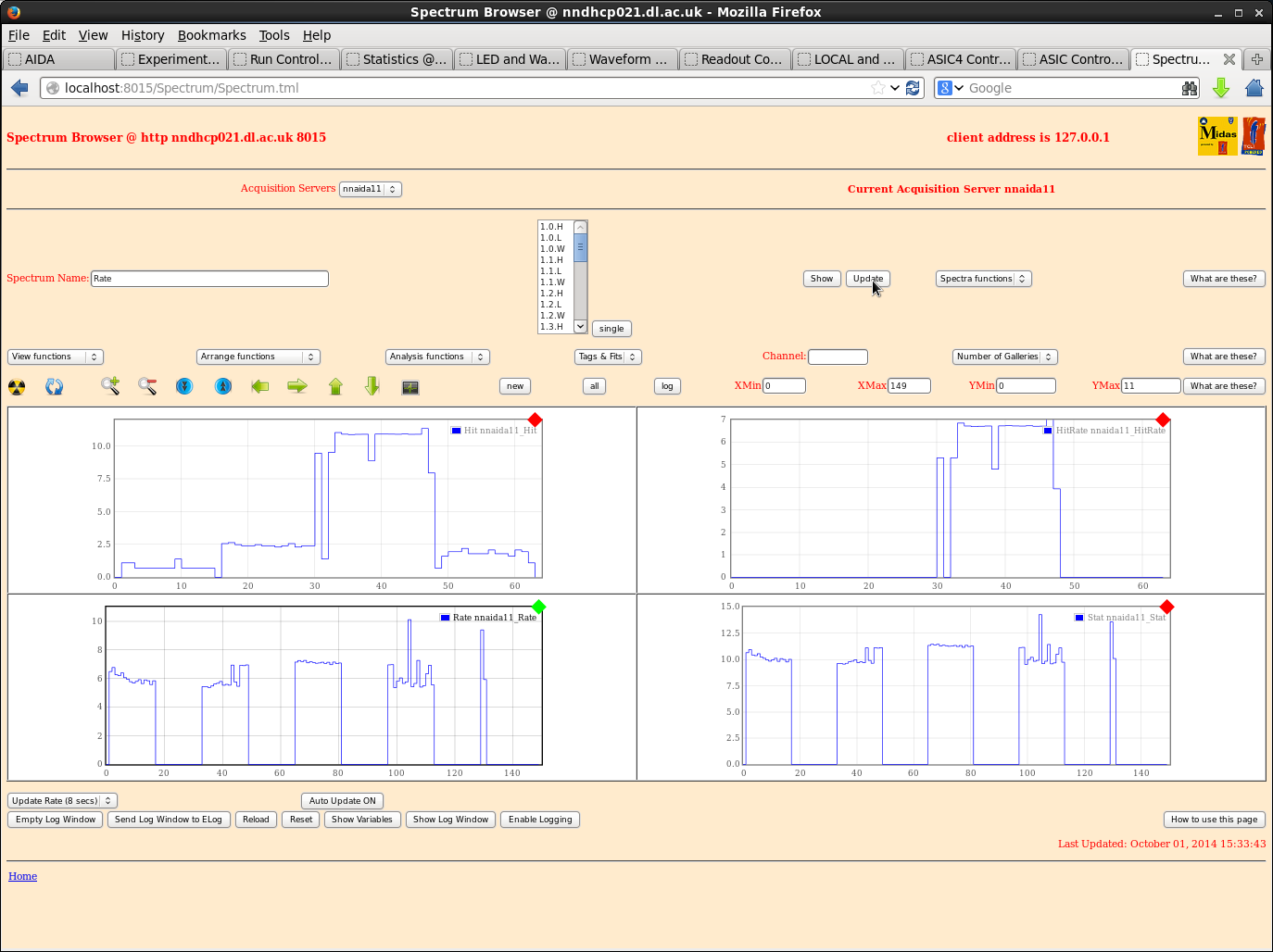
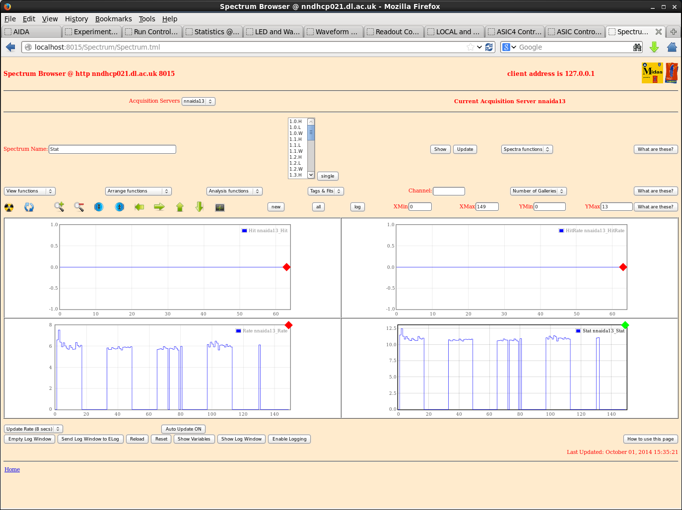
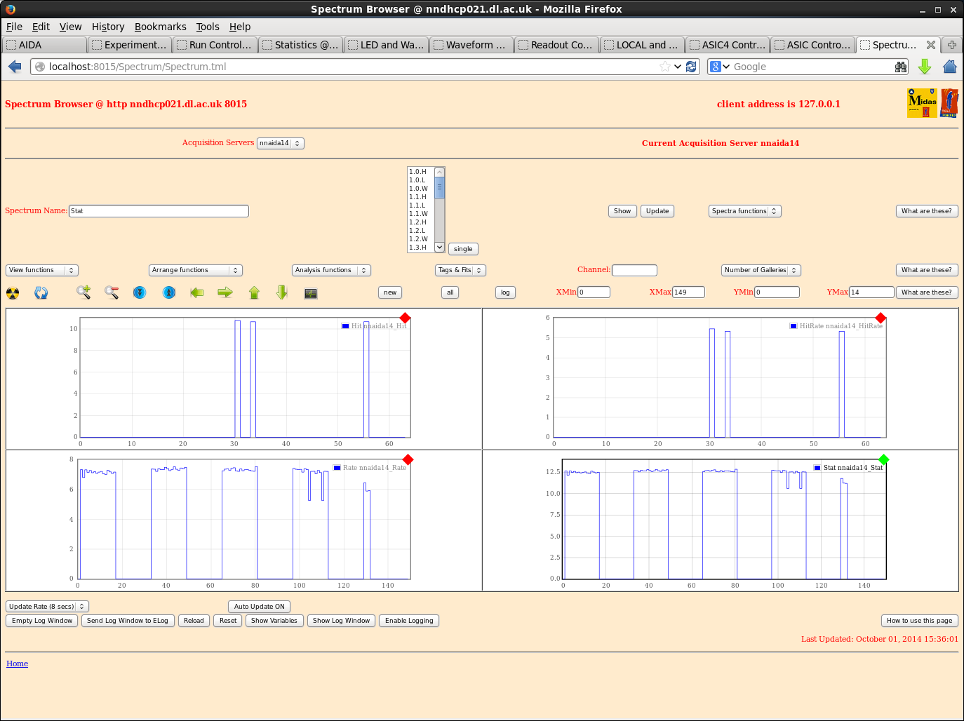
Stat spectra look roughly the same as those included in the above entry.
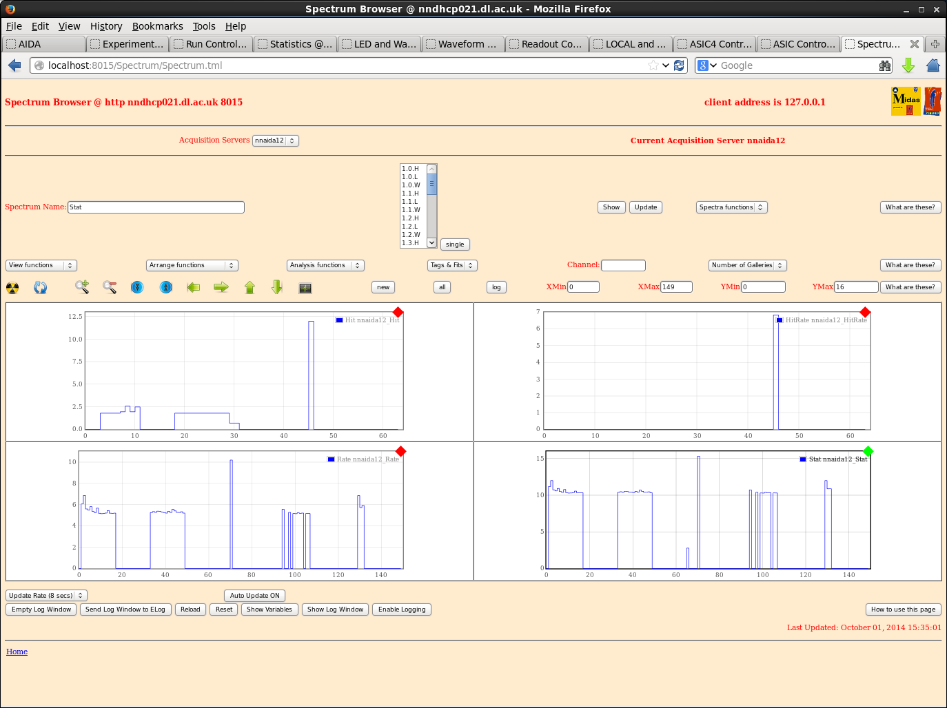
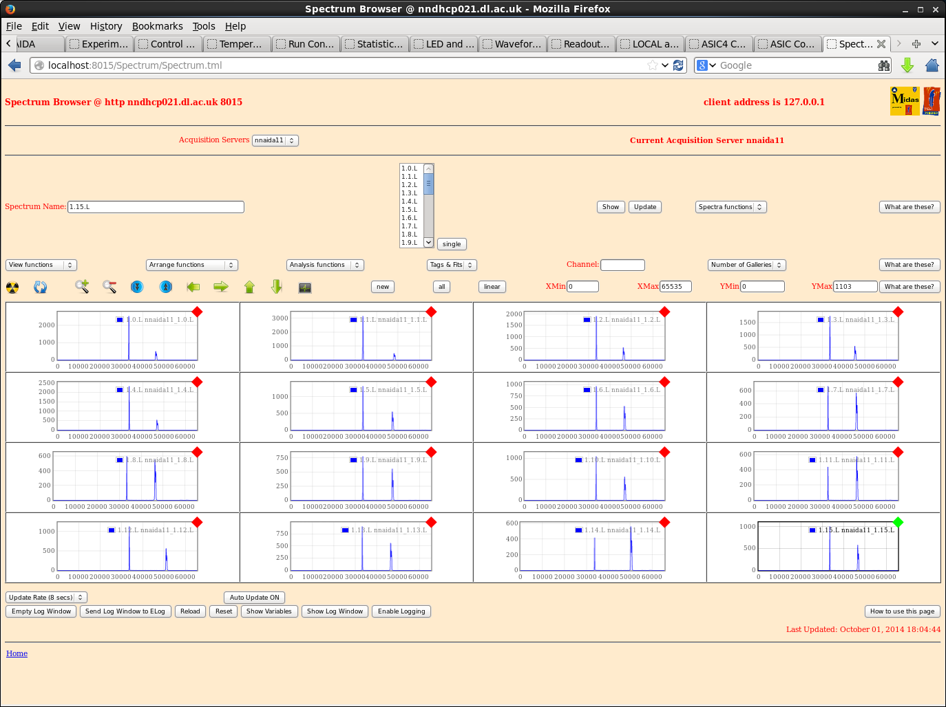
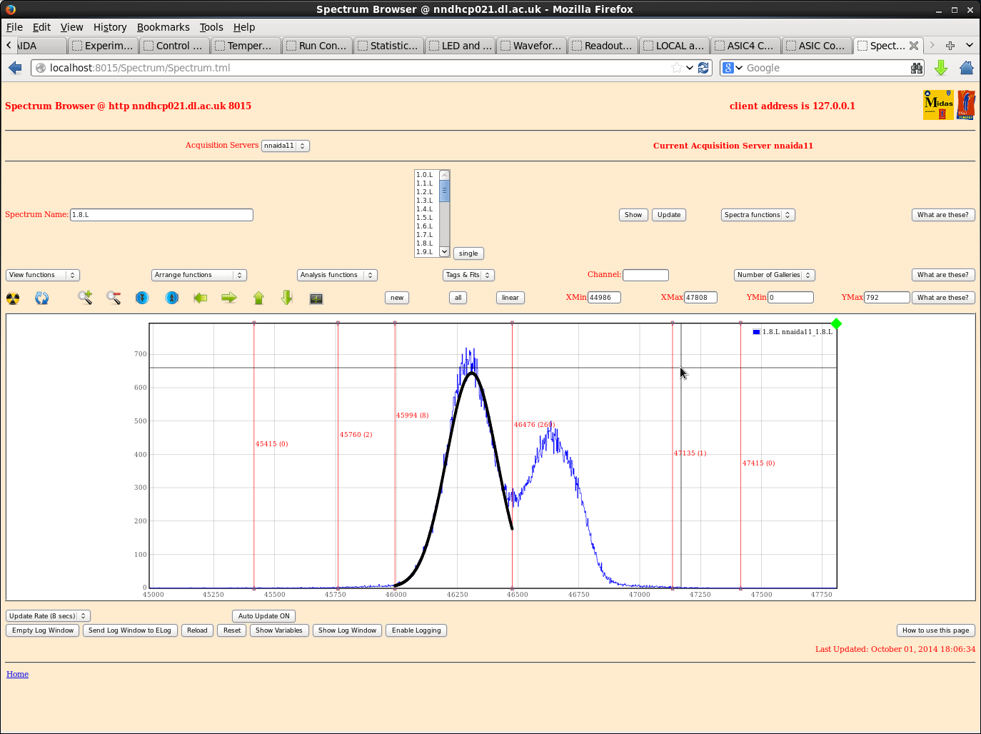
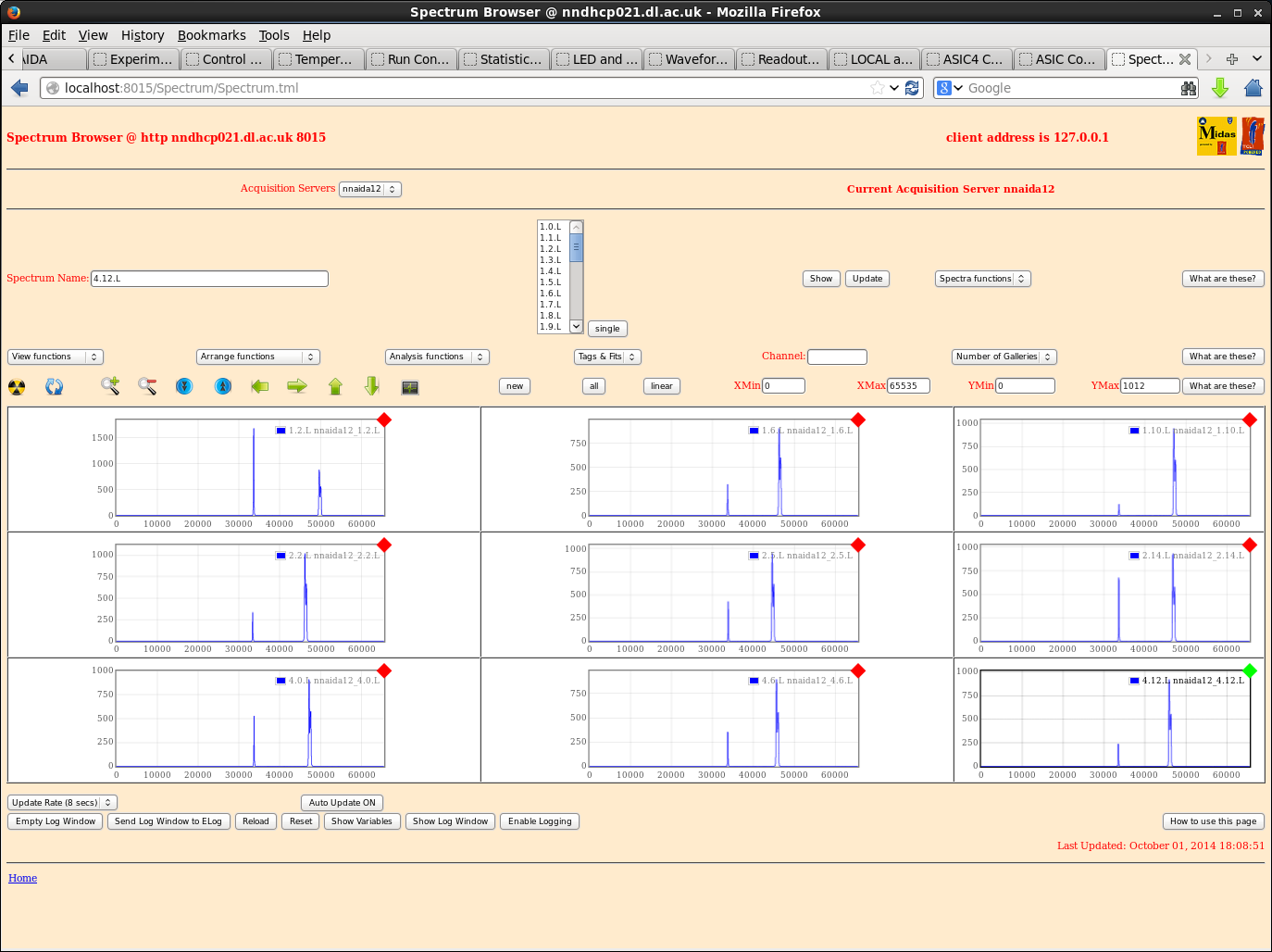
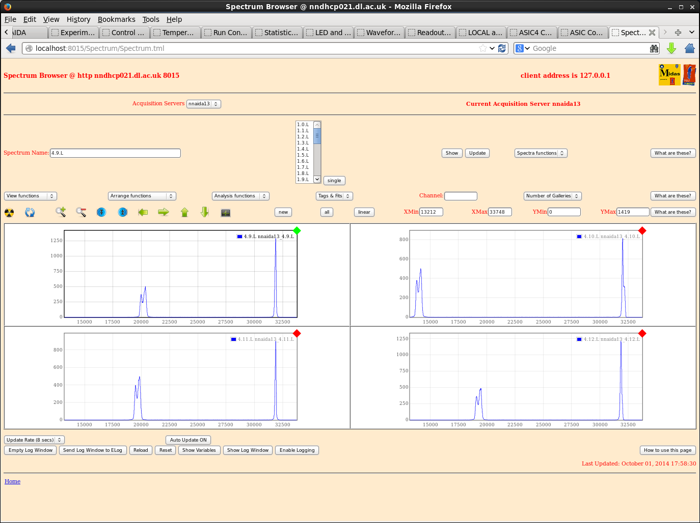
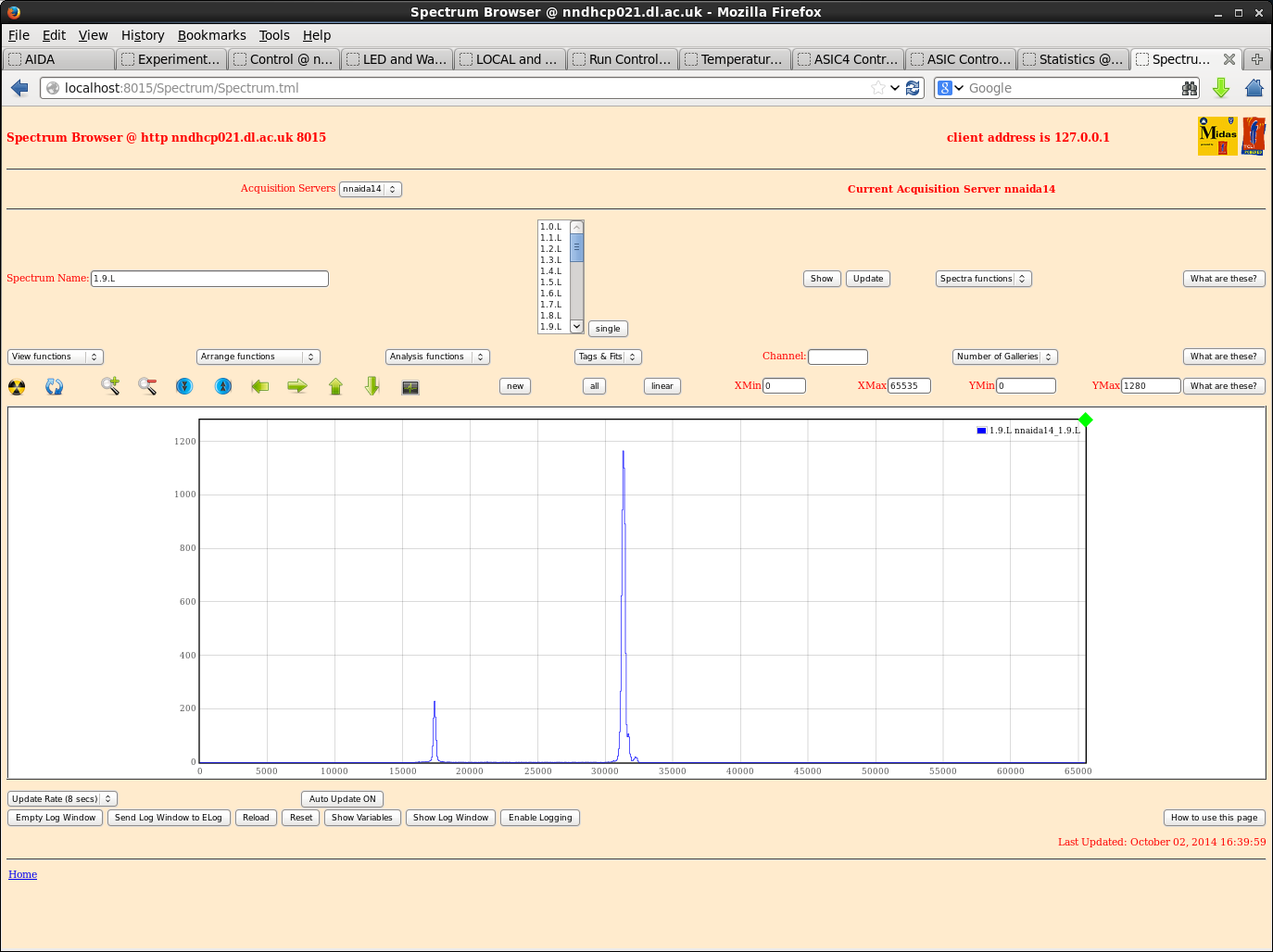
Now see large peak around ~32k, present in all spectra to some degree. Mostly larger than corresponding pulser peak.
Power cycled several times, reloaded+checked ASIC settings etc., no change. Any ideas? Have I forgotten something?
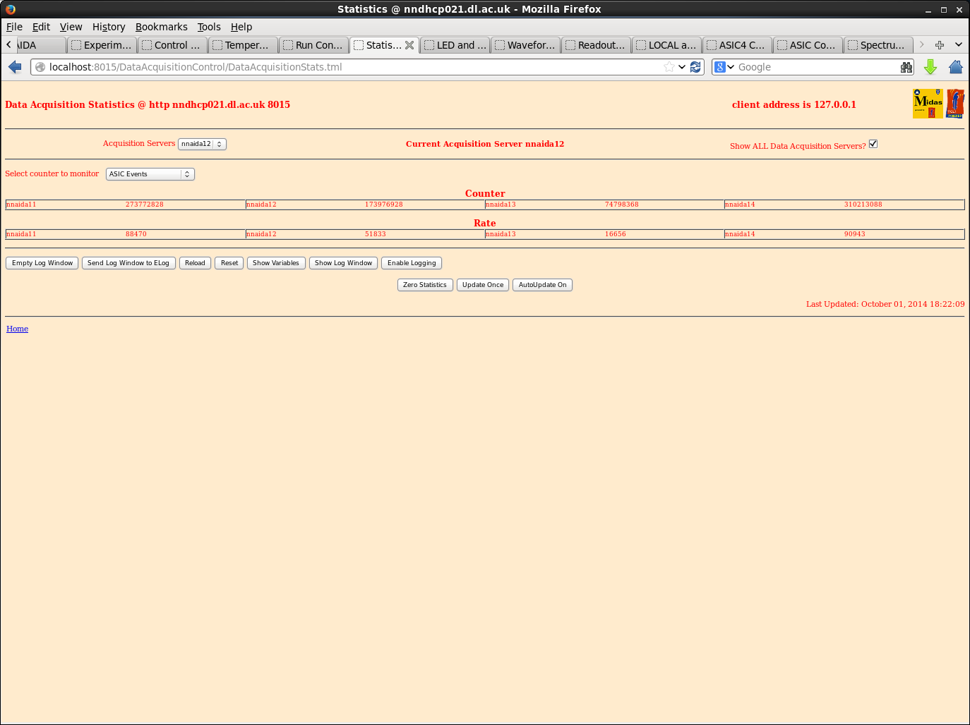
The ASIC events stats rate is also very high on nnaida11,12,14. 13 is high but not excessively.
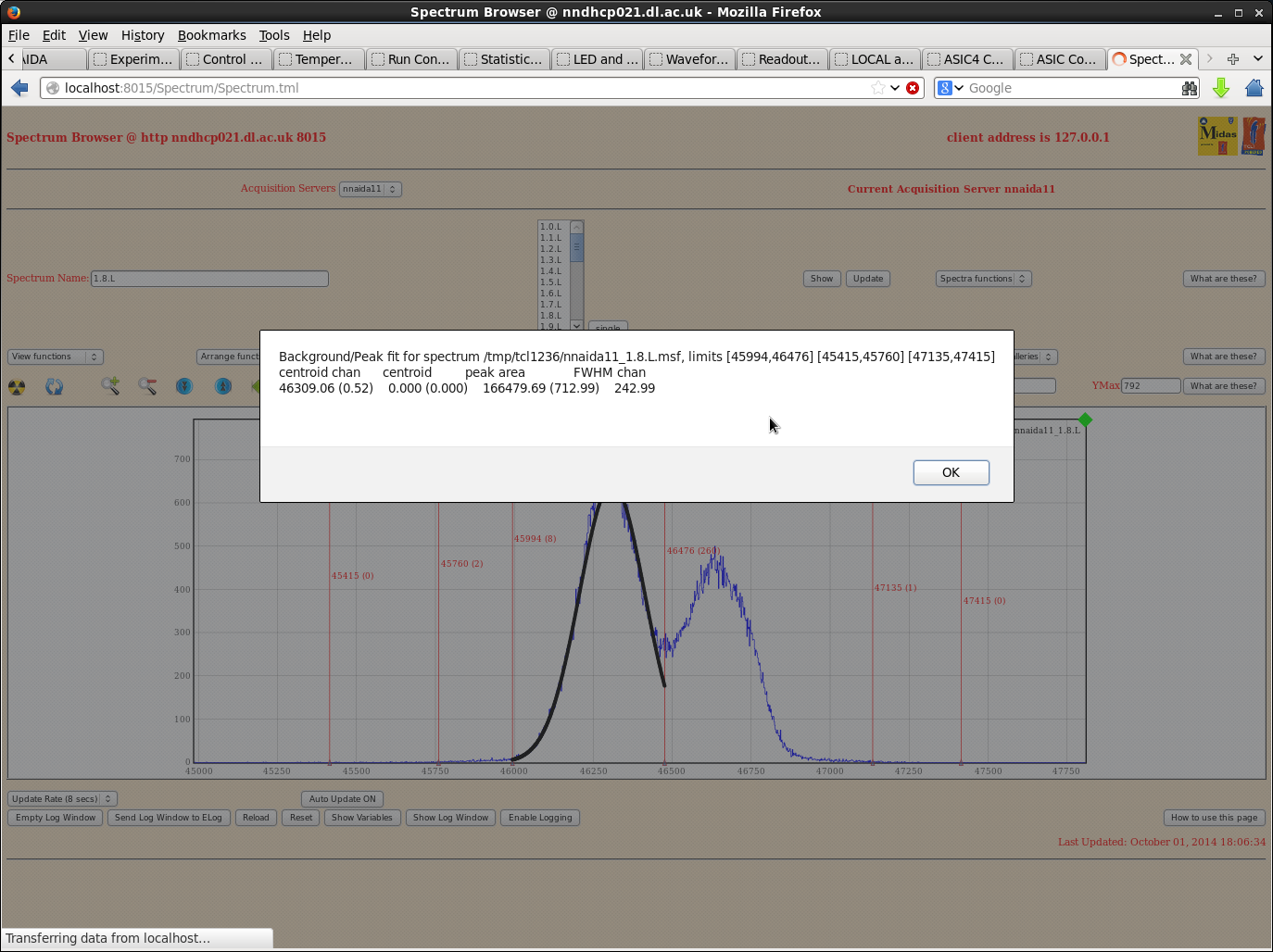
Pulser peak shows double peaking on all ASIC channels with individual widths of ~250ch and total width of ~500ch.
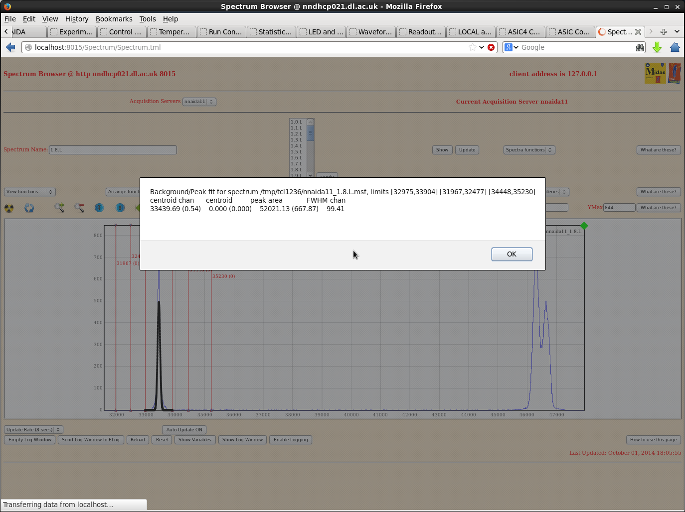
Noise peak has width ~50ch. This has reduced somewhat (was ~100s ch) with my last power cycle, but clearly still not gone.
I'll try again in the morning, but if no change will proceed with the shaping time tests with the spectra as they are.
|
| Attachment 1: nnaida12_stats.png
|
|
| Attachment 2: nnaida11_stats.png
|
|
| Attachment 3: nnaida13_stats.png
|
|
| Attachment 4: nnaida14_stats.png
|
|
| Attachment 5: nnaida11_allnoise.png
|
|
| Attachment 6: nnaida11_noisefit.png
|
|
| Attachment 7: nnaida11_peakfit.png
|
|
| Attachment 8: nnaida11_peakfit2.png
|
|
| Attachment 9: nnaida12_few.png
|
|
| Attachment 10: nnaida13_asic4_noise.png
|
|
| Attachment 11: ASICevents_stats.png
|
|
|
16
|
Sun Oct 5 22:42:56 2014 |
Chris Griffin | DL tests on 02/10/14 |
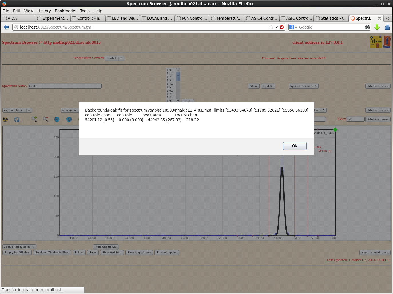
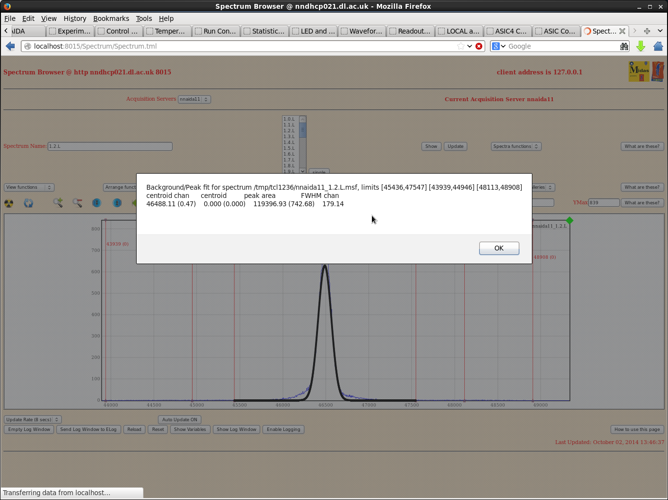
A late entry for the work I carried out on Thursday.
With the Emco box providing the HV, the pulser peak showed double (or triple) peaks. This was not seen with the SY1527 so I thought this would be better for looking at peak widths.
Same ASIC settings my previous entry, and a HV of 200V with leakage current 3.8uA.
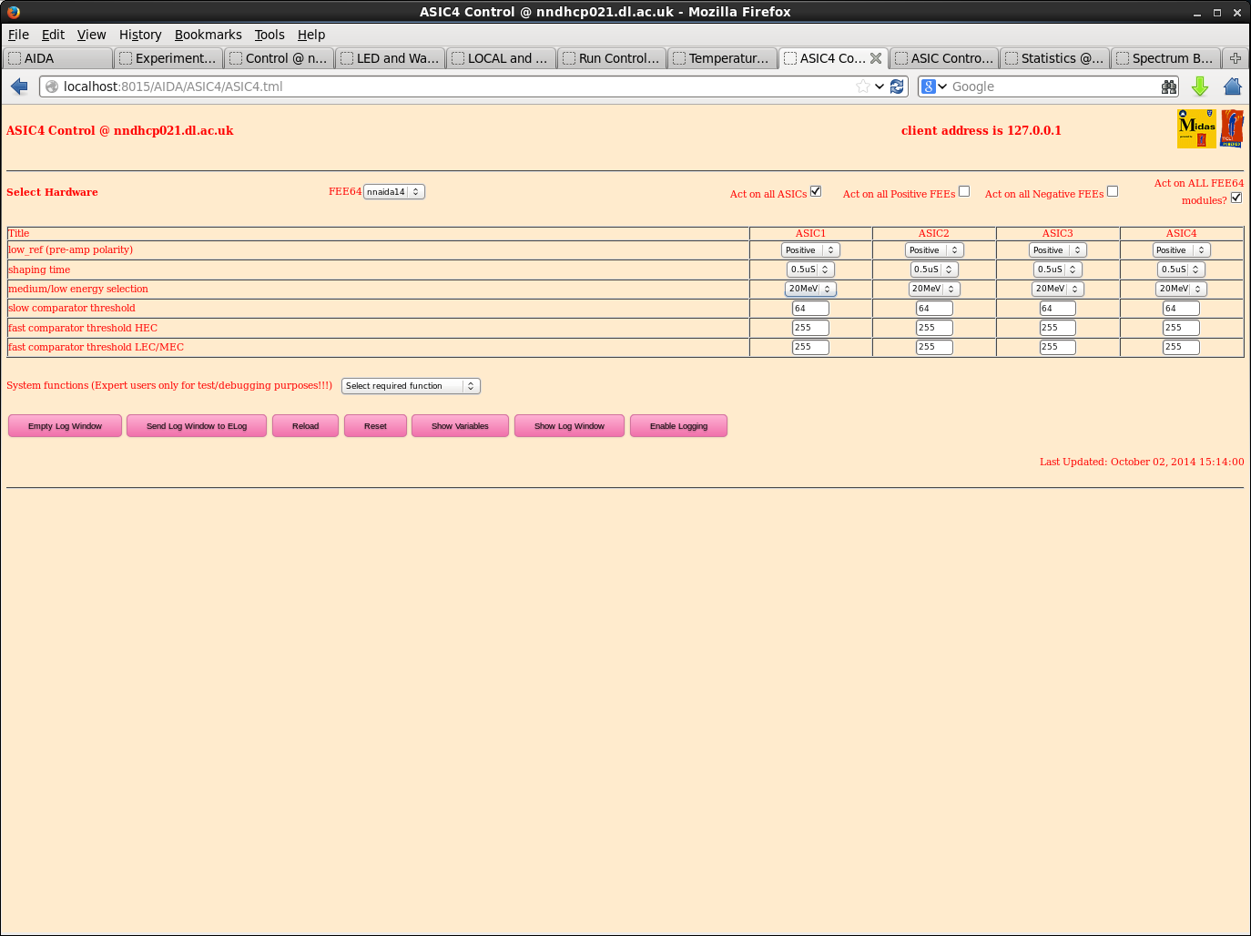
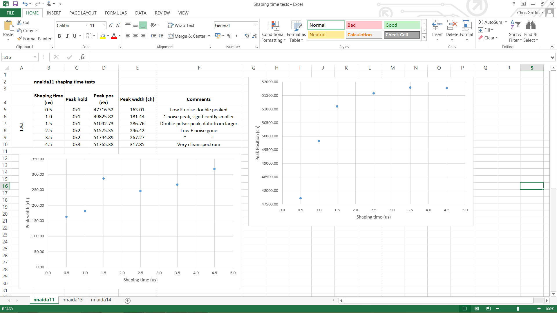
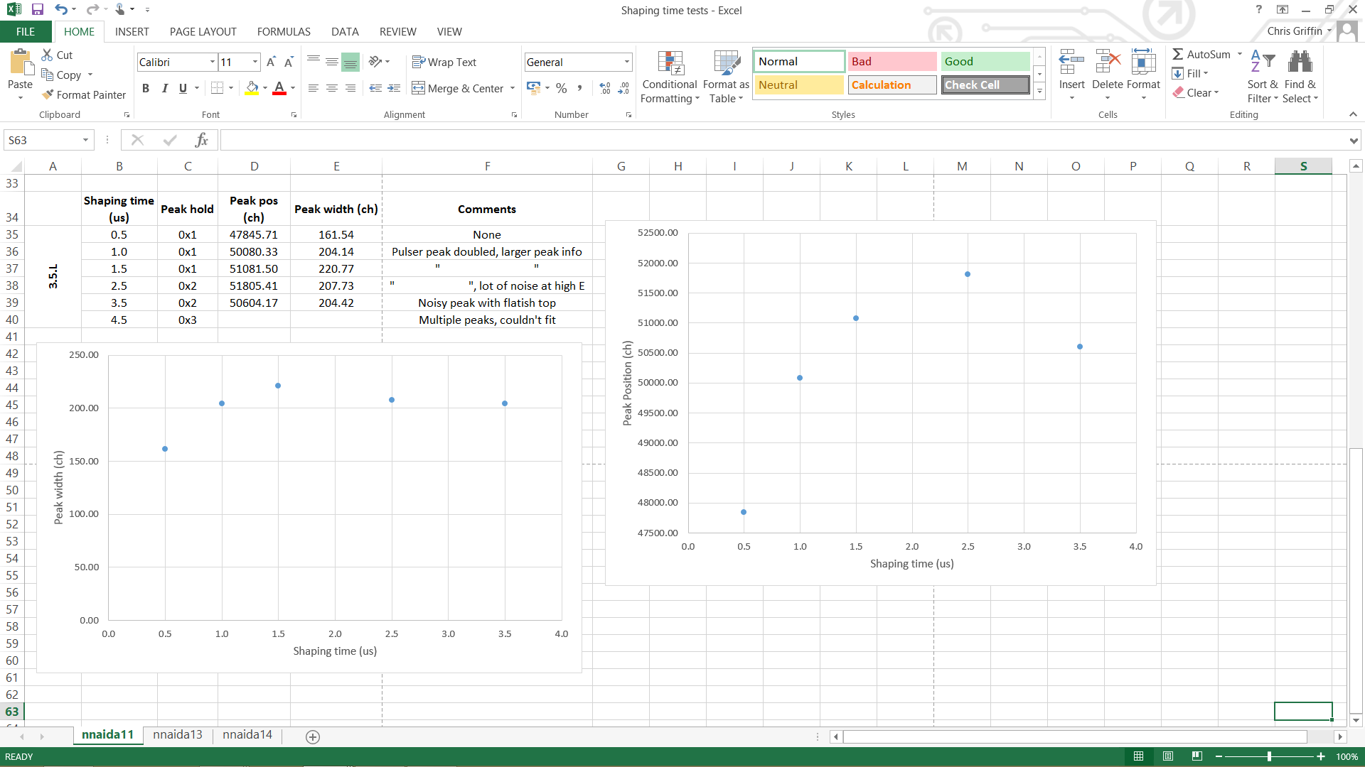
I varied the shaping time in each module using the ASIC4 control page as this also changes the hold time automatically. Slow comparitor threshold of 64.
Checked each module and took sample channels from a couple of ASICs in each but made qualitative comparisons with random channels in all ASICs to make sure the chosen ones were representative of the ASIC/module as a whole.
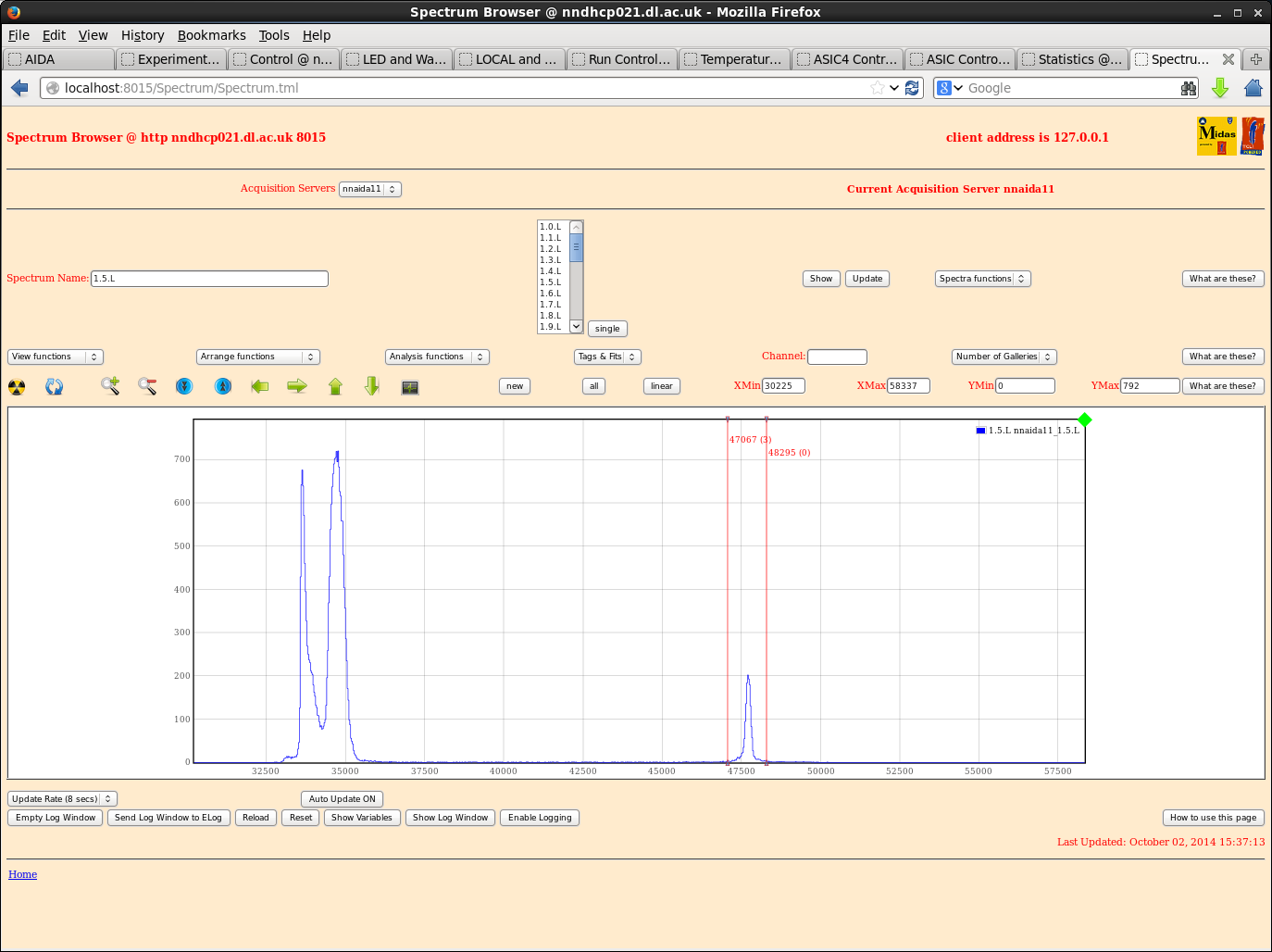
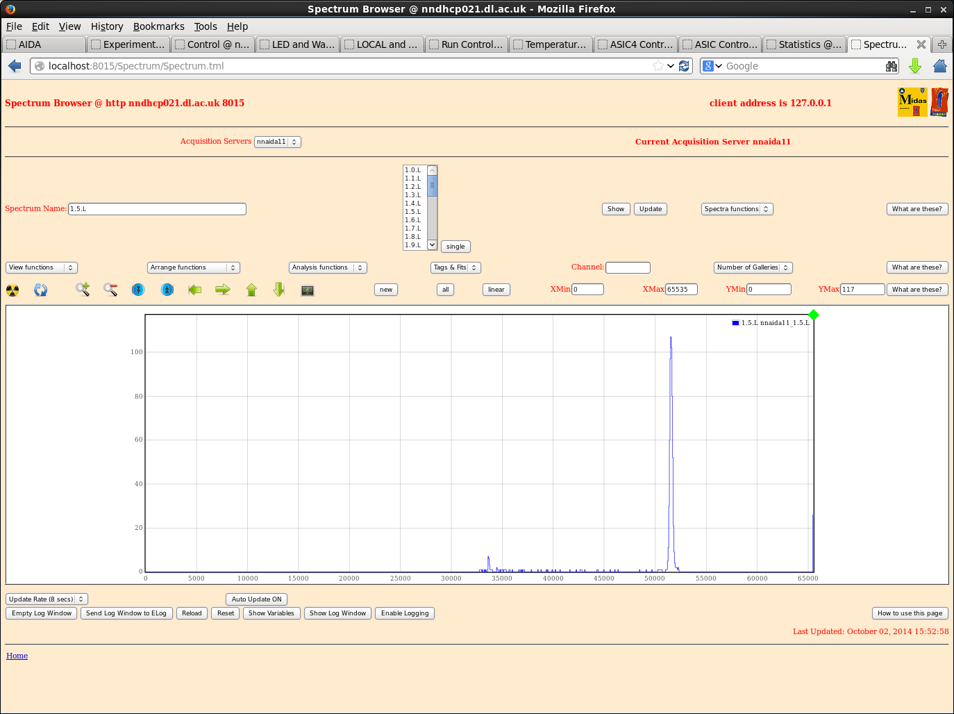
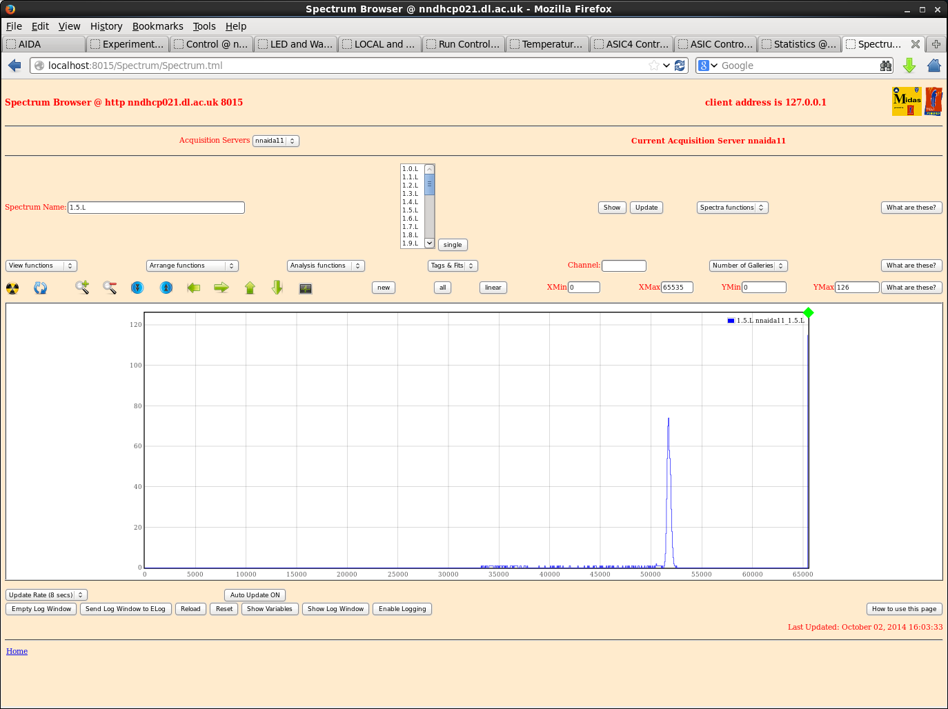
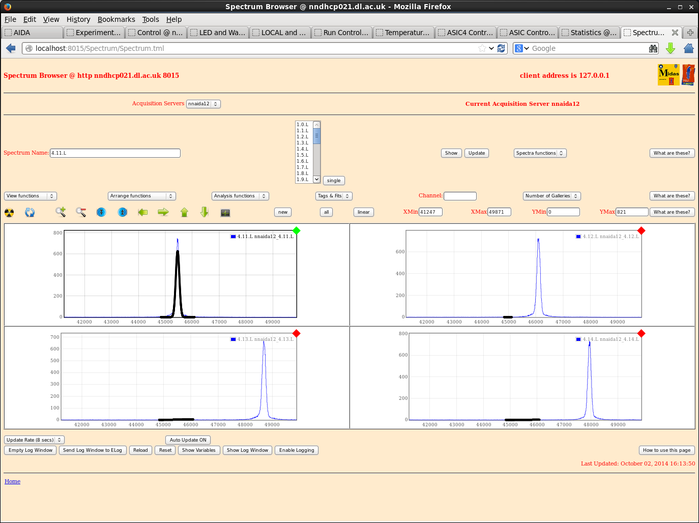
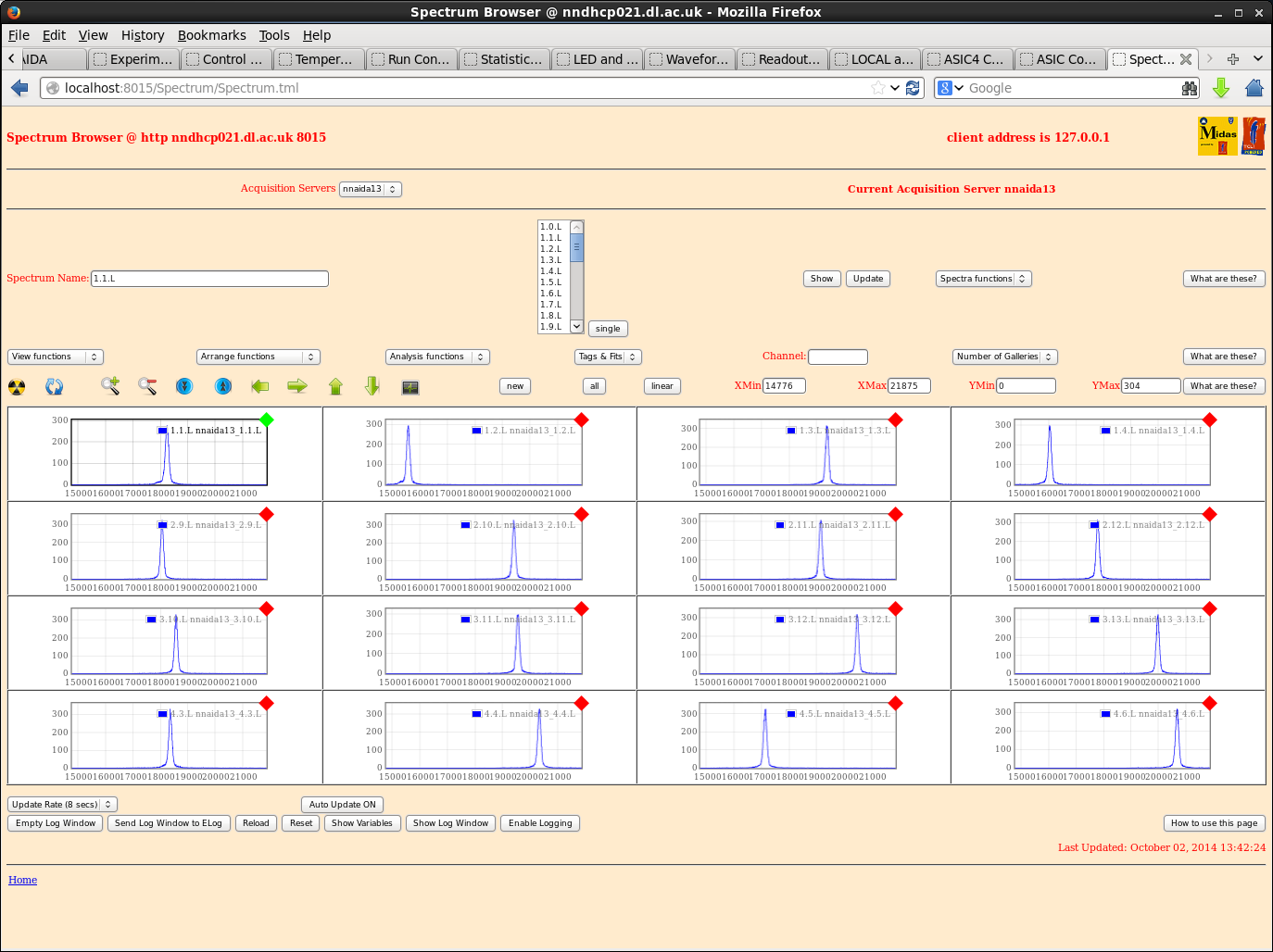
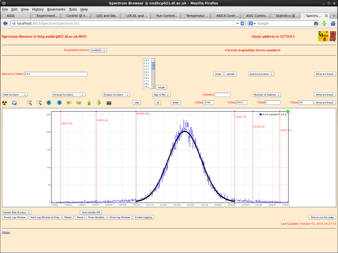
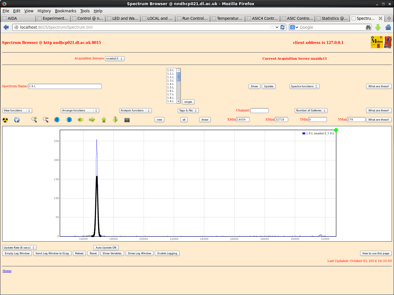
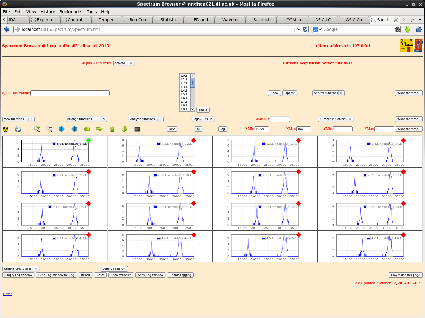
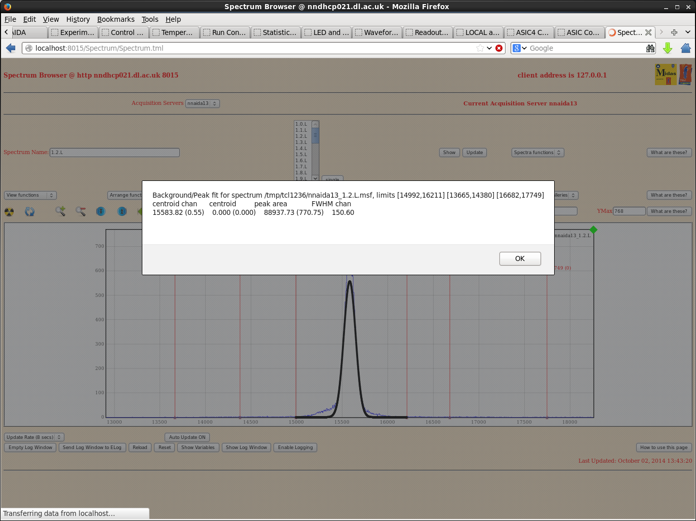
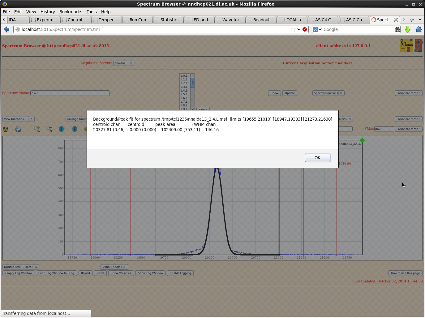
Tables and graphs are included below for nnaida11 and 13. nnaida13 showed a high level of low E noise on some spectra, but the pulser peaks were always well defined single peaks.
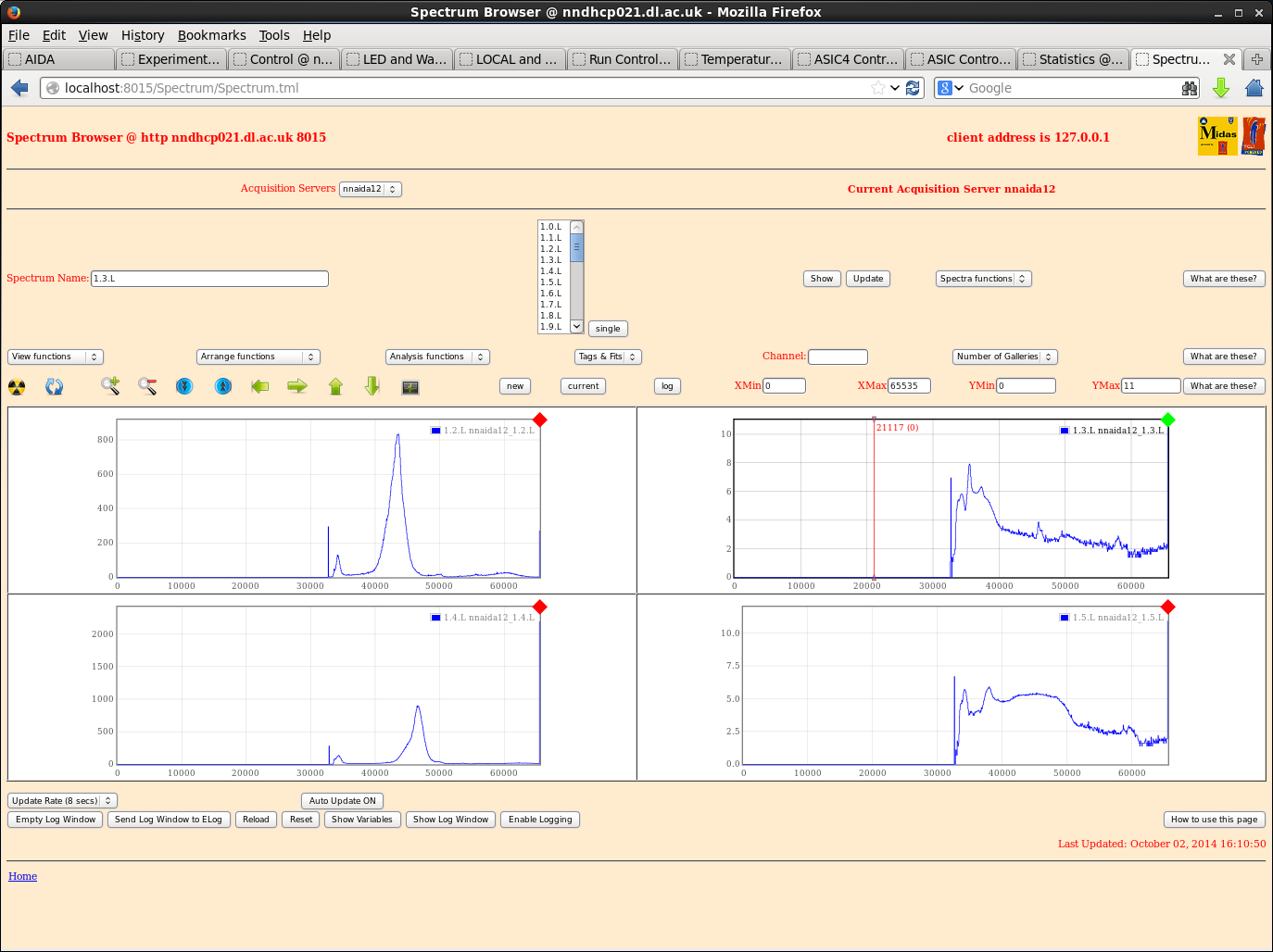
nnaida12 showed noises across the full range of many spectra in all ASICs apart from ASIC4. Patrick suggested this module may possibly be suffering and need replacing. A quick scan through some channels showed:
- average peak width @ shaoing time of 0.5us of ~150-180 ch
- same at shaping times of 2.5 and 4.5us. Noise present over full range throughout
My taxi was arriving so I didn't have chance to go through nnaida14 in depth, but a quick scan showed peak widths within ~10-15ch of those seen in nnaida13. |
| Attachment 1: ASIC4control-orig.png
|
|
| Attachment 2: nnaida11-SY1527spec.png
|
|
| Attachment 3: nnaida11-SY1527_2.5stWide.png
|
|
| Attachment 4: nnaida11-SY1527_4.5st.png
|
|
| Attachment 5: nnaida11-SY1527_4.8.Lpeak3.5st.png
|
|
| Attachment 6: nnaida11-Sy1527peakEx.png
|
|
| Attachment 7: nnaida11-1.5.L-excel.png
|
|
| Attachment 8: nnaida11-3.5.L-excel.png
|
|
| Attachment 9: nnaida12-SY1527_FSnoise.png
|
|
| Attachment 10: nnaida12-SY1527good.png
|
|
| Attachment 11: nnaida13-SY1527peaks.png
|
|
| Attachment 12: nnaida13-SY1527_0.5st.png
|
|
| Attachment 13: nnaida13-SY1527_1.5st.png
|
|
| Attachment 14: nnaida13-SY1527noise.png
|
|
| Attachment 15: nnaida13-SY1527peakEx.png
|
|
| Attachment 16: nnaida13-SY1527peakEx2.png
|
|
| Attachment 17: nnaida14-SY1527_1st.png
|
|
|
886
|
Wed Aug 9 14:40:28 2023 |
Carole, Nic, Jeroen | AIDA HV SUPPLY & PULSER TEST |
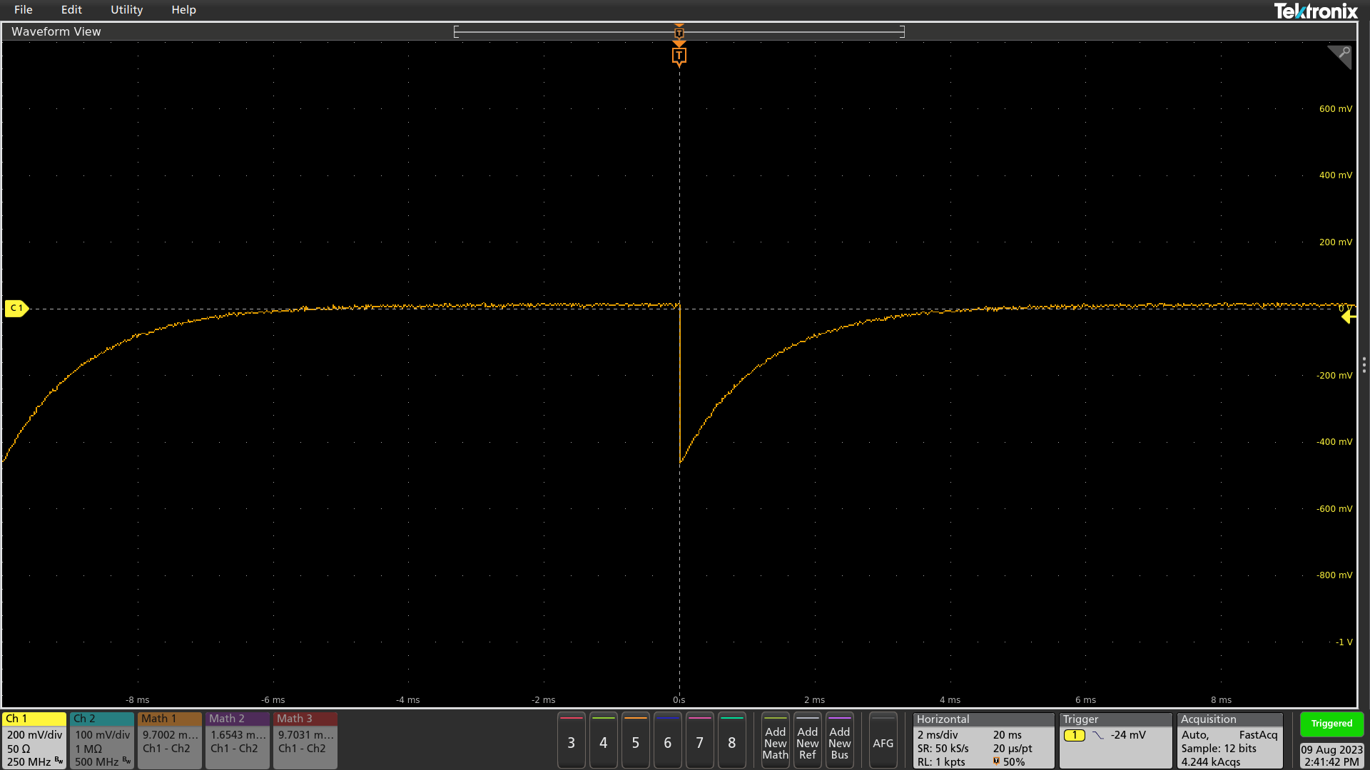
Tests with the HV supply (CAEN N1419ET) and Pulse Generator ( BNC PB-5 ) in the detector lab on the crate behind the DEGAS detectors, carried out the 9th August 2023
Both modules were plugged
Test 1: pulse generetor on 2 Hz
- DC, 50 ohm - HV OFF - attachment 1
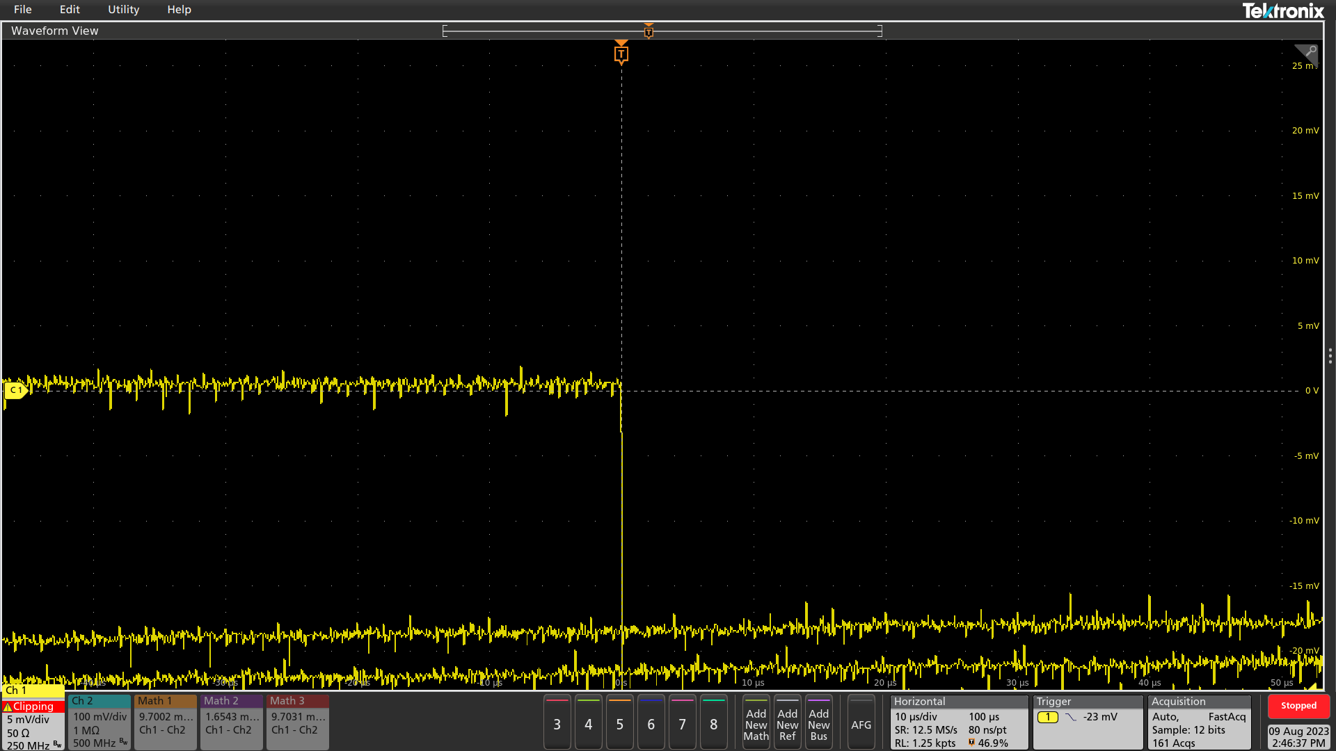
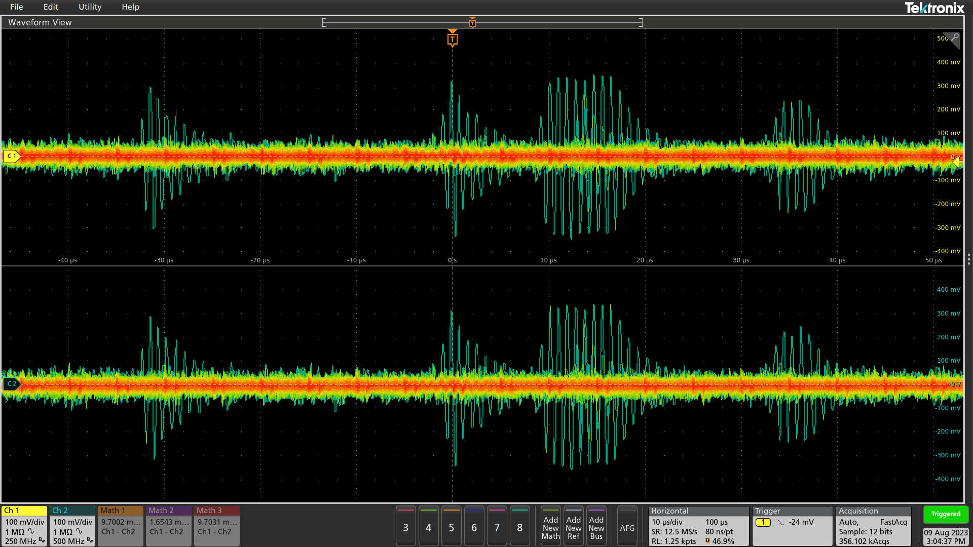
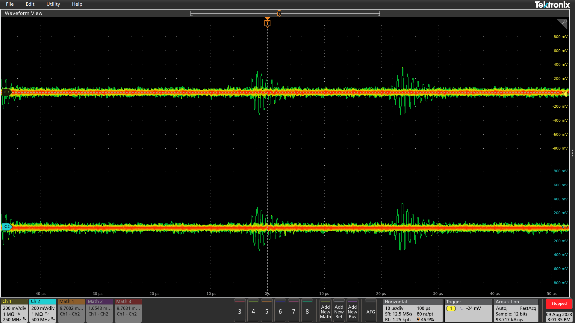
- DC, 50 ohm - HV OFF, Zoom on the noise - attachment 2
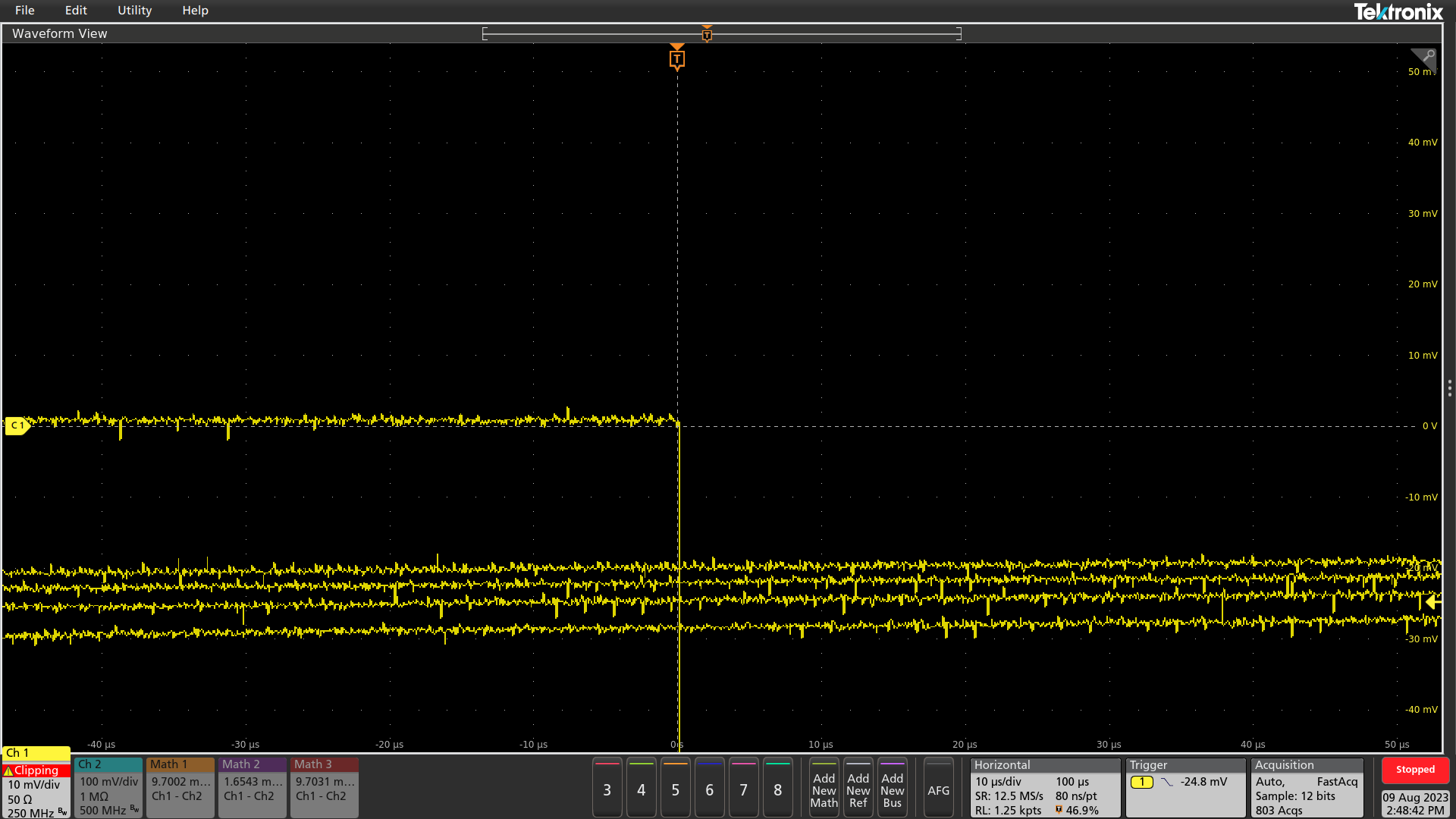
- DC, 50 ohm - HV 50 V, Zoom on the noise - attachment 3
Test 2: HV supply Channel 1 - CORE and 2 - BRAID, pulse generator still on
- AC 1 Mohm - HV OFF - attachment 4
- AC 1 Mohm - HV 50 V - attachment 5
No differences were observed between crate OFF, HV OFF and HV 50 V. An important periodic noise (green on the pictures) was observed and was significantly smaller when unpluging the HV module from the crate. The thickness of the baseline noise seems to be comparable to entry 882, attachment 33-35.
|
| Attachment 1: AIDA_PulserTest_0908_FullPulse.png
|
|
| Attachment 2: AIDA_PulserTest_09.08_5mV_10us_HVOFF.png
|
|
| Attachment 3: AIDA_PulserTest_0908_10mV_10us_50HV.png
|
|
| Attachment 4: HV_0V_090823_1500_wPulser.png
|
|
| Attachment 5: HV_-50V_090823_1500_wPulser.png
|
|
|
190
|
Fri Apr 29 11:11:20 2016 |
CG,PV,TD | Friday 29 April |
MSL type BB18 serial # 2977-20 bias +100V I_L +12.0uA T=23 deg C
(biased by nnaida # 3 & 5 )

DSSSD - AIDA adaptor PCB cabling

4 off LH Coupler (Kapton PCB, 5cm), 2x 34-way Samtec ribbon cable (62cm p+n, 53cm n+n),
RH coupler(Kapton PCB, 10cm)
 + 3M 1245 1.4mil copper foil screen ribbon cables (i.e. not RH & LH couplers)
 + drain wires -> gold-plated Lemo-00 test input connectors

to FEE64s in 4x FEE module crates

Snout drain wire to FEE module Cu block

nnaida 3 & 8 AIDA adaptor PCB rev C
nnaida 5 & 9 AIDA adaptor PCB rev C (LK1 fitted)
ground links LK3 & LK7 fitted to nnaida3, 5, 8, & 9 AIDA adaptor PCBs

*** Note added 11.58 sat 30 Apr 2016
Detector bias cable to nnaida3 & 5 adaptor PCBs *but* LK1 fitted to nnaida9 *not* nnaida5.
This has been set this way since start of current series of tests Wed 27 April. Connecting
via a different adaptor PCB to that connected to the CAEN N1419 bias supply causes significant
noise issues presumably due to high resistance path via 2x adaptor PCB to DSSSD cables
and the DSSSD bias bus line on the DSSSD.

Heavy duty copper cable connects copper front end frames of FEE modules
Nitto 5011N conductive gasket between FEE module and front end frames

Standard ASIC settings
 nnaida 3 & 8 - negative input
 nnaida 5 & 9 - positive input

Pulser BNC PB-4
Fall time 1.0ms
Rate c.100Hz
Delay min
Amplitude 50,000
Polarity -
Pulse top Tail
Atten 10x
+ polarity via EG&G Ortec 433A Sum & Invert Amplifier

Pulser peak widths broad, structured, non gaussian c. 200ch FWHM

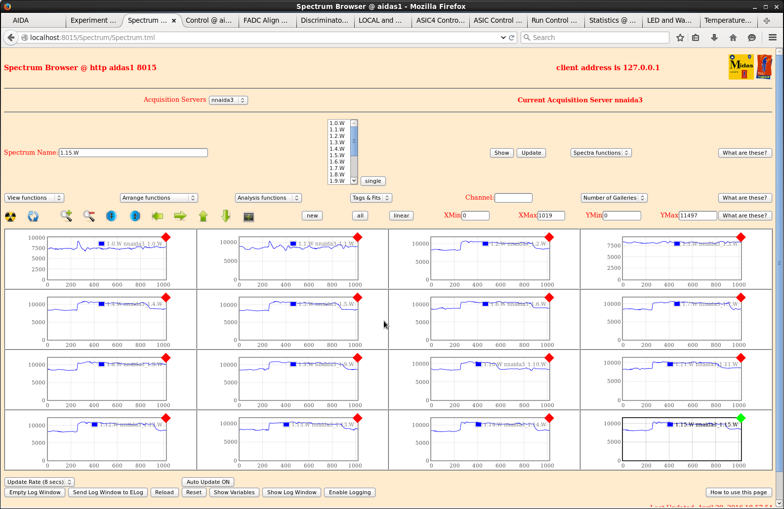
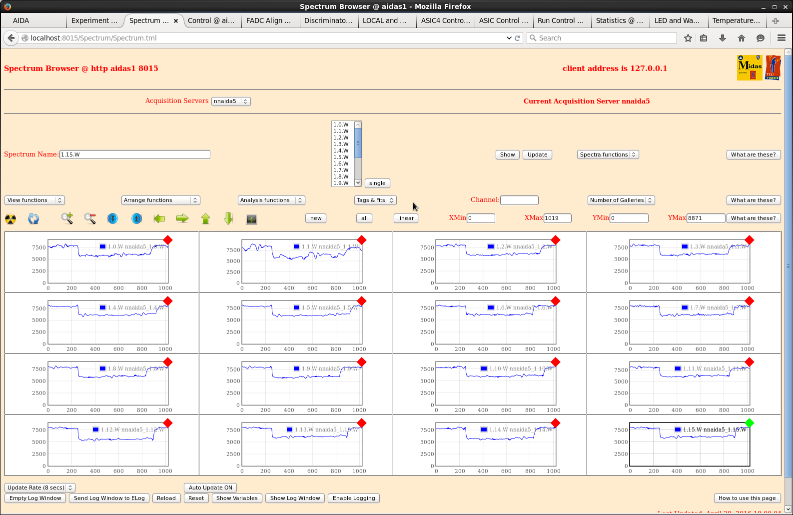
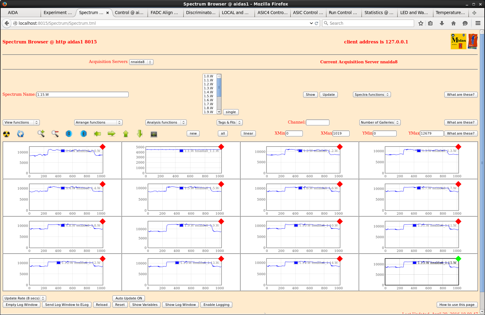
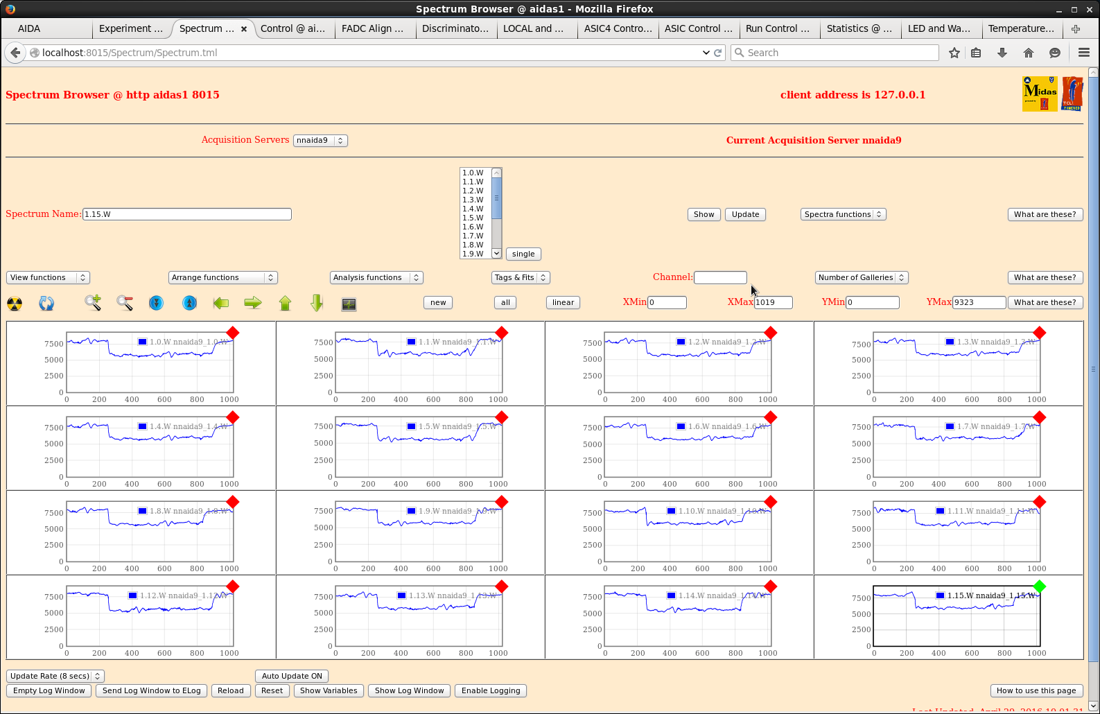
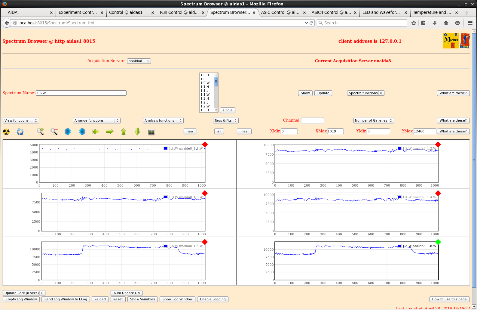
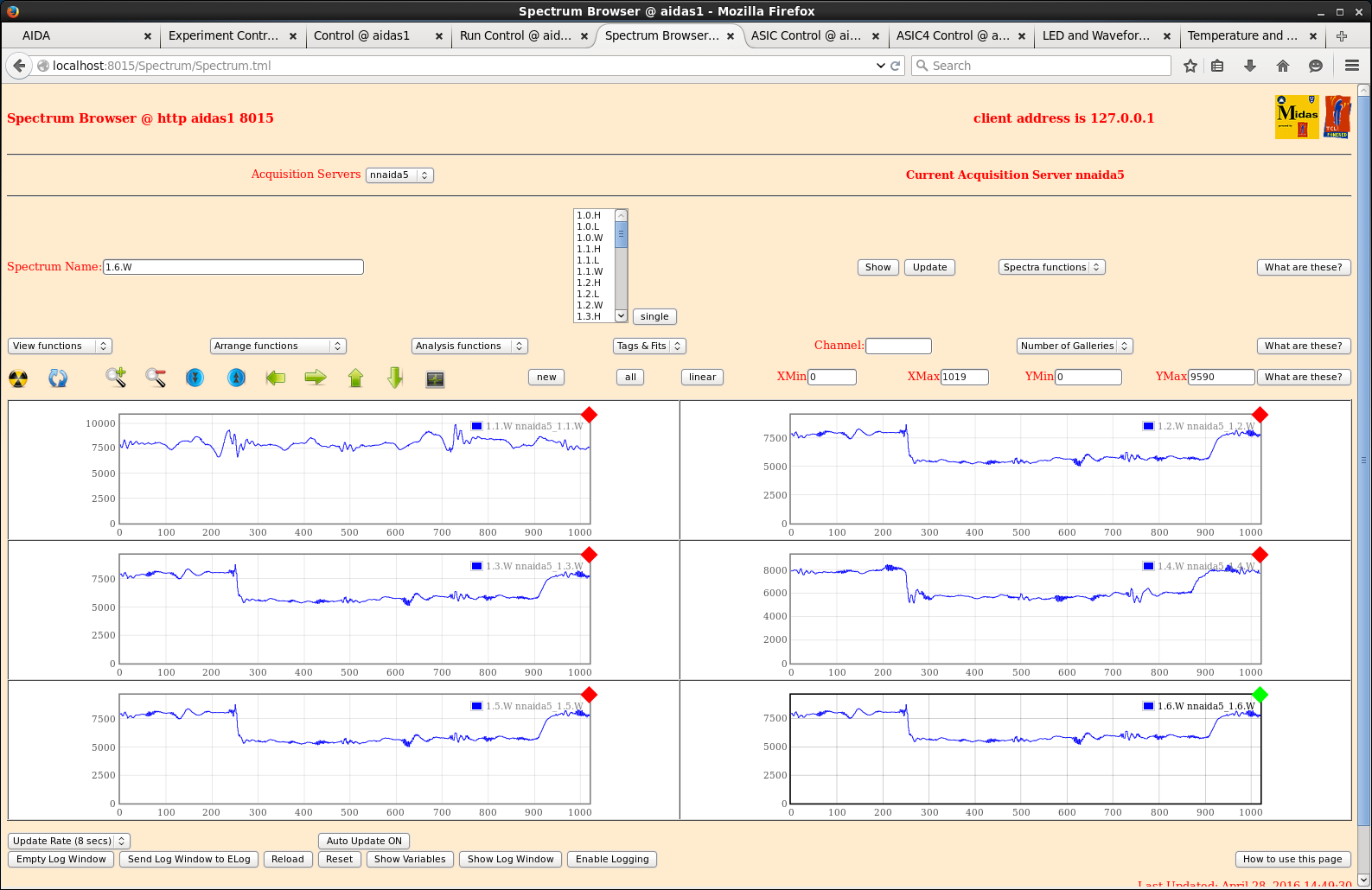
attachments 1-4 ASIC # 1 waveforms for each acqserver with all acqservers connected to same PSU

attachments 5-6 for comparison, from yesterday, with acqservers from two different PSUs - note
absence of HF noise in attachments 1-4 cf. attachments 5-6. |
| Attachment 1: nnaida3_-_nnaida3_5_8_9_to_1xPSU.png
|
|
| Attachment 2: nnaida5_-_nnaida3_5_8_9_to_1xPSU.png
|
|
| Attachment 3: nnaida8_-_nnaida3_5_8_9_to_1xPSU.png
|
|
| Attachment 4: nnaida9_-_nnaid3_5_8_9_to_1xPSU.png
|
|
| Attachment 5: nnaida8_wav_1DSSD_4crates_400chFWHM.png
|
|
| Attachment 6: nnaida5_wav_1DSSD_4crates_250chFWHM.png
|
|
|
191
|
Sat Apr 30 07:46:47 2016 |
CG,PV,TD | Saturday 30 April 2016 |
MSL type BB18 serial # 2977-20 bias +100V I_L +12.45uA T=23 deg C
(biased by nnaida # 3 & 5 )

DSSSD - AIDA adaptor PCB cabling

4 off LH Coupler (Kapton PCB, 5cm), 2x 34-way Samtec ribbon cable (62cm p+n, 53cm n+n),
RH coupler(Kapton PCB, 10cm)
 + 3M 1245 1.4mil copper foil screen ribbon cables (i.e. not RH & LH couplers)
 + drain wires -> gold-plated Lemo-00 test input connectors

to FEE64s in 4x FEE module crates

3M 1245-wrapped cables enclosed by polyethyelene bags (supplied to deliver 90cm Printech Kapton PCBs)
to ensure no electrical contact with snout, DSSSD mounting tubes, snout base etc

Snout drain wire to FEE module Cu block

nnaida 3 & 8 AIDA adaptor PCB rev C
nnaida 5 & 9 AIDA adaptor PCB rev C (LK1 fitted)
ground links LK3 & LK7 *not* fitted to nnaida3, 5, 8, & 9 AIDA adaptor PCBs
LK1 fitted to nnaida5 ( cf. https://elog.ph.ed.ac.uk/AIDA/190 )

Heavy duty copper cable connects copper front end frames of FEE modules
Nitto 5011N conductive gasket between FEE module and front end frames

Standard ASIC settings
 nnaida 3 & 8 - negative input
 nnaida 5 & 9 - positive input

Pulser BNC PB-4
Fall time 1.0ms
Rate c.100Hz
Delay min
Amplitude 50,000
Polarity -
Pulse top Tail
Atten 10x
+ polarity via EG&G Ortec 433A Sum & Invert Amplifier

Standard ASIC settings

Shaping time 8us
LEC/MEC Slow com 32 (dec)
        Fast com 32 (dec)
HEC Fast com 2(dec)

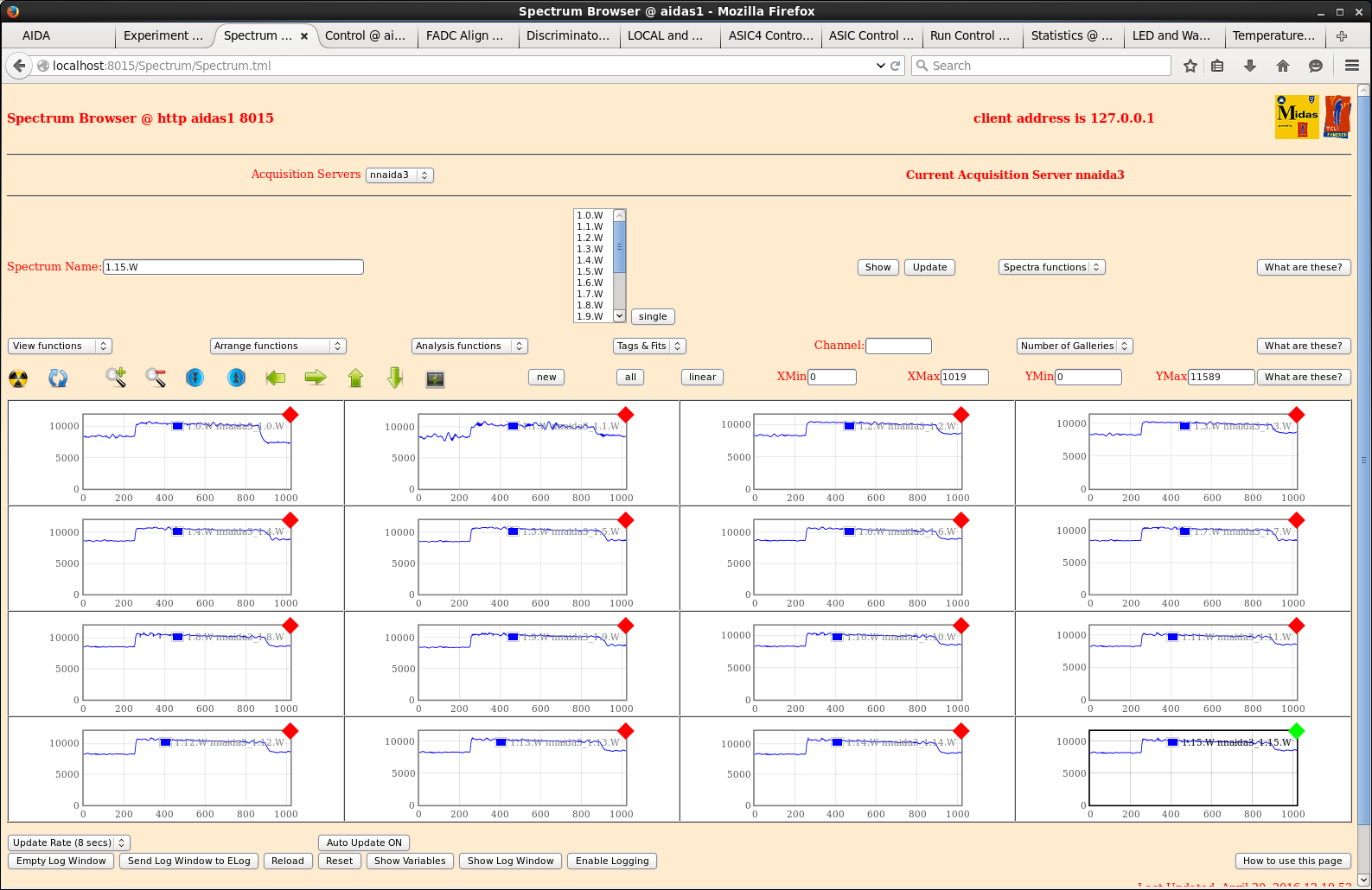
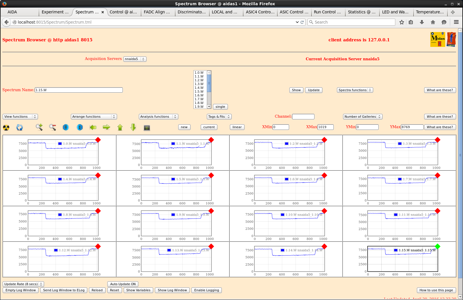
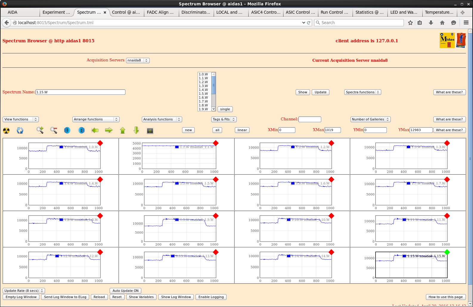
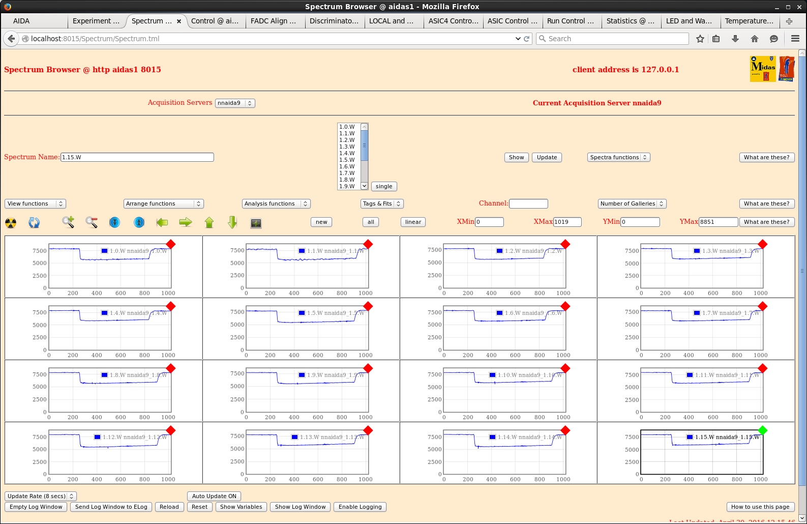
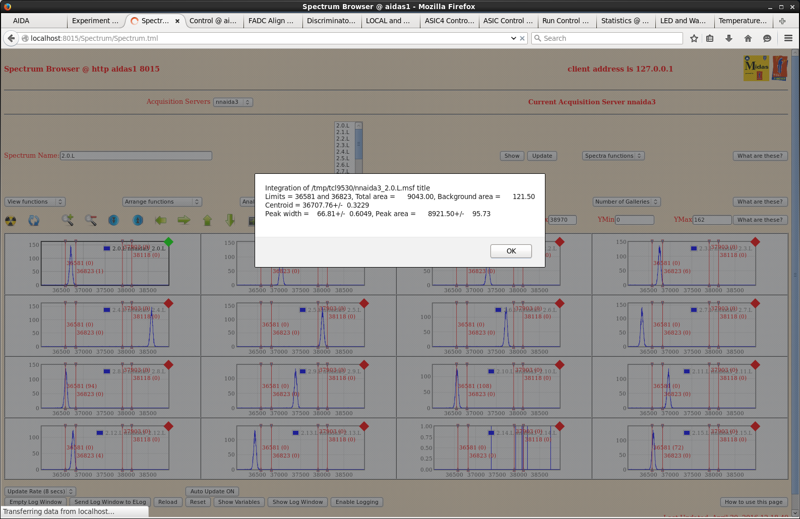
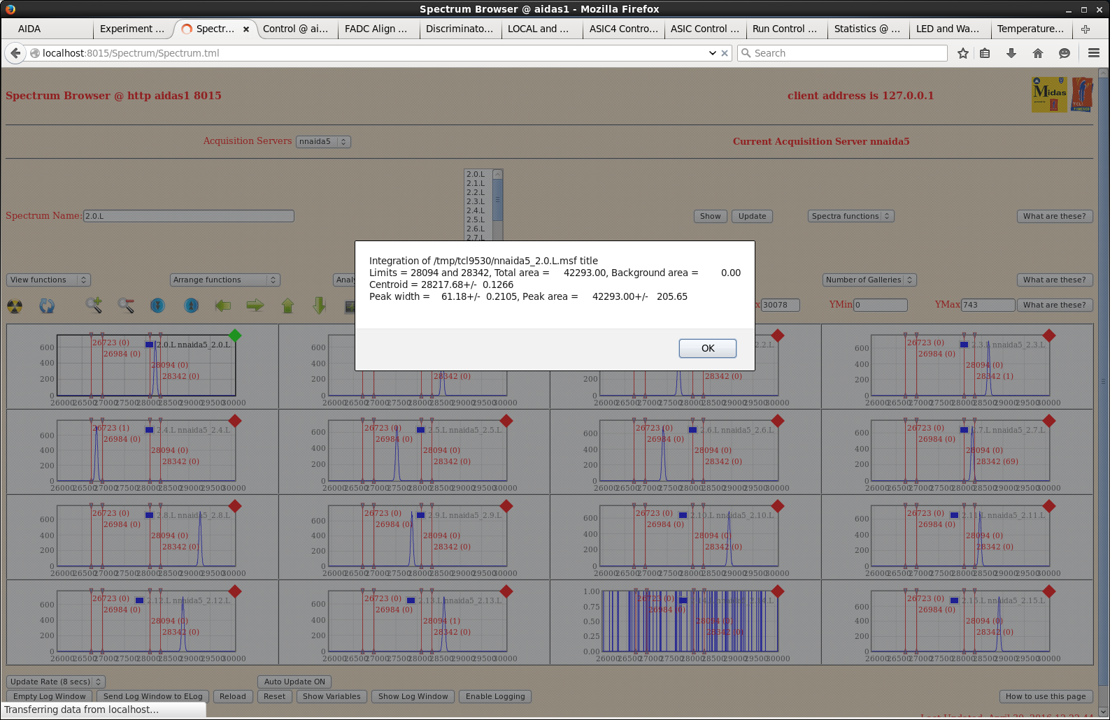
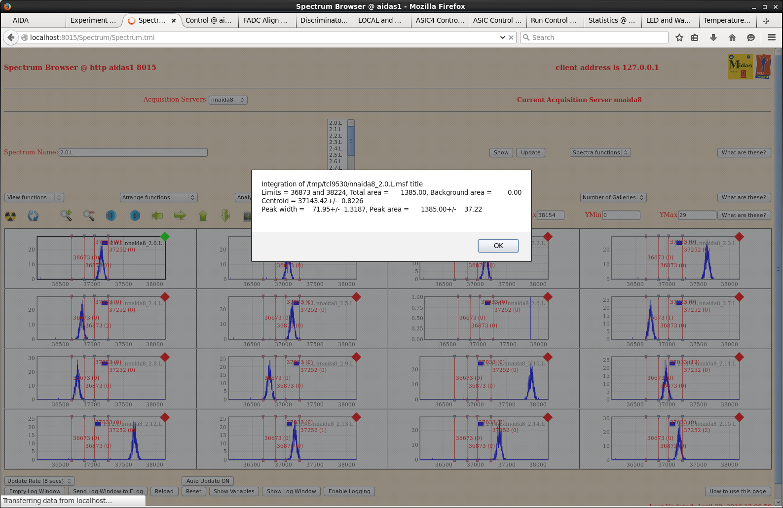
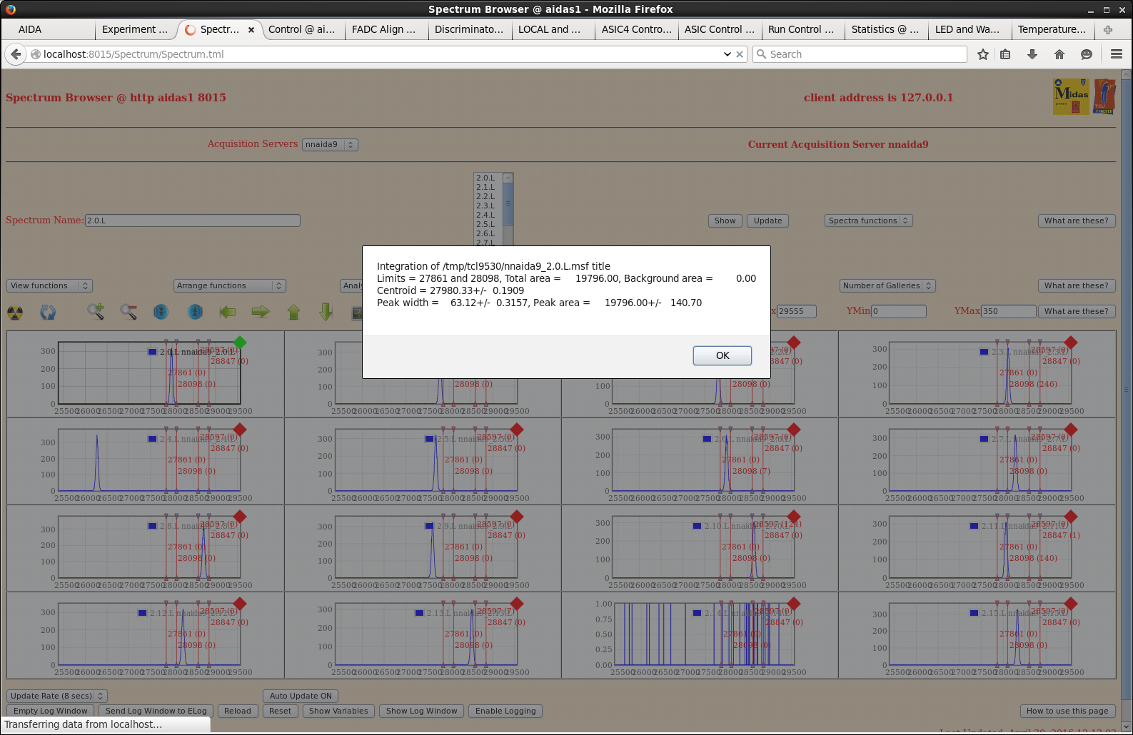
Attachments 1-4 ASIC #1 waveforms from each FEE64
            5-8 ASIC #2 spectra + 2.0.L pulser peak width

Pulser peak widths (ch FWHM) versus shaping time ( spectrum 2.4.L )

tau nnaida3 nnaida5 nnaida8 nnaida9
 8   68      60      70      62
 4   83      49      88      48
 2  100      47     109      43
 1  172      60     165      42
0.5 380      86     309      48

Note: n+n ohmic strips spectra > 100 ch FWHM display non-gaussian peaks/double peaking

15.45 Attempted to increase detector bias from +100V to +150V
      Leakage current increased ~0.5uA/V for bias > 115V
      Detector bias supply trips (20uA) at +120V
      Remain at detector bias +100V

16.17 Switch polarity of detector bias from + to -
      Move LK1 from nnaida5 to nnaida3

tau nnaida3 nnaida5 nnaida8 nnaida9
 8   61      64      65      61

n+n ohmic strips ~10% improvement, p+n junction strips no significant change

16.30 Fit LK3/LK7 jumpers to connect adaptor PCB ground to detector PCB ground

tau nnaida3 nnaida5 nnaida8 nnaida9
 8   61      64      62      60

No significant change to cf. previous test

18.30 Install second DSSSD

Upstream   3058-6  bias +100V I_L 4.15uA
Downstream 2977-20 bias +100V I_L 11.8uA
+ 207Bi source ~3cm upstream of 3058-6

Standard ASIC settings
shaping time 6us
slow comp 8(dec)
HEC fast comp 2(dec)
LEC/MEC fast comp 16(dec)

Pulser peak widths ~60 ch FWHM per previous tests today

Discriminator masks TBD

22.27 R2 to disk (directory /data20/TapeData/May2016)
      MERGE data links 2-9

Run data to disk overnight. Add two more DSSSDs tomorrow.

09.21 R2 stopped |
| Attachment 1: nnaida3_wav_nnaida5Lk1_cableBags.png
|
|
| Attachment 2: nnaida5_wav_nnaida5Lk1_cableBags.png
|
|
| Attachment 3: nnaida8_wav_nnaida5Lk1_cableBags.png
|
|
| Attachment 4: nnaida9_wav_nnaida5Lk1_cableBags.png
|
|
| Attachment 5: nnaida3_spec_nnaida5Lk1_cableBags.png
|
|
| Attachment 6: nnaida5_spec_nnaida5Lk1_cableBags.png
|
|
| Attachment 7: nnaida8_spec_Lk1nnaida5_cablesBags.png
|
|
| Attachment 8: nnaida9_spec_nnaida5Lk1_cableBags.png
|
|
| Attachment 9: 1.png
|
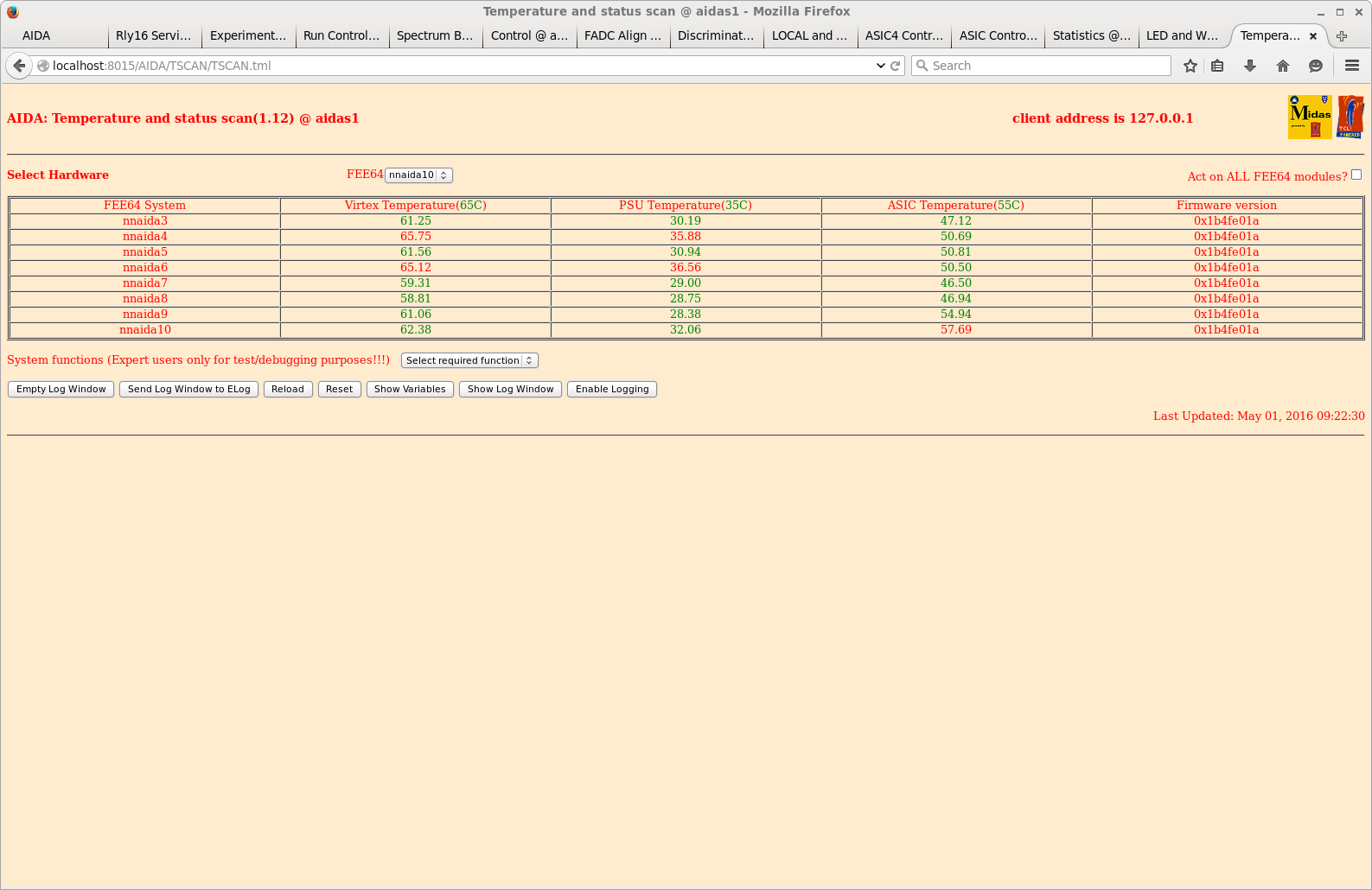
|
| Attachment 10: 2.png
|
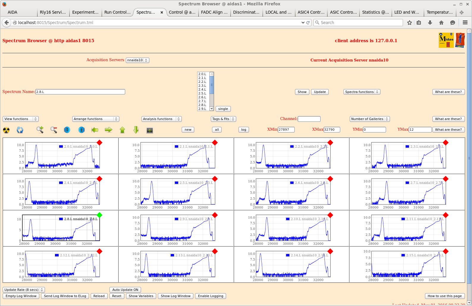
|
| Attachment 11: 3.png
|
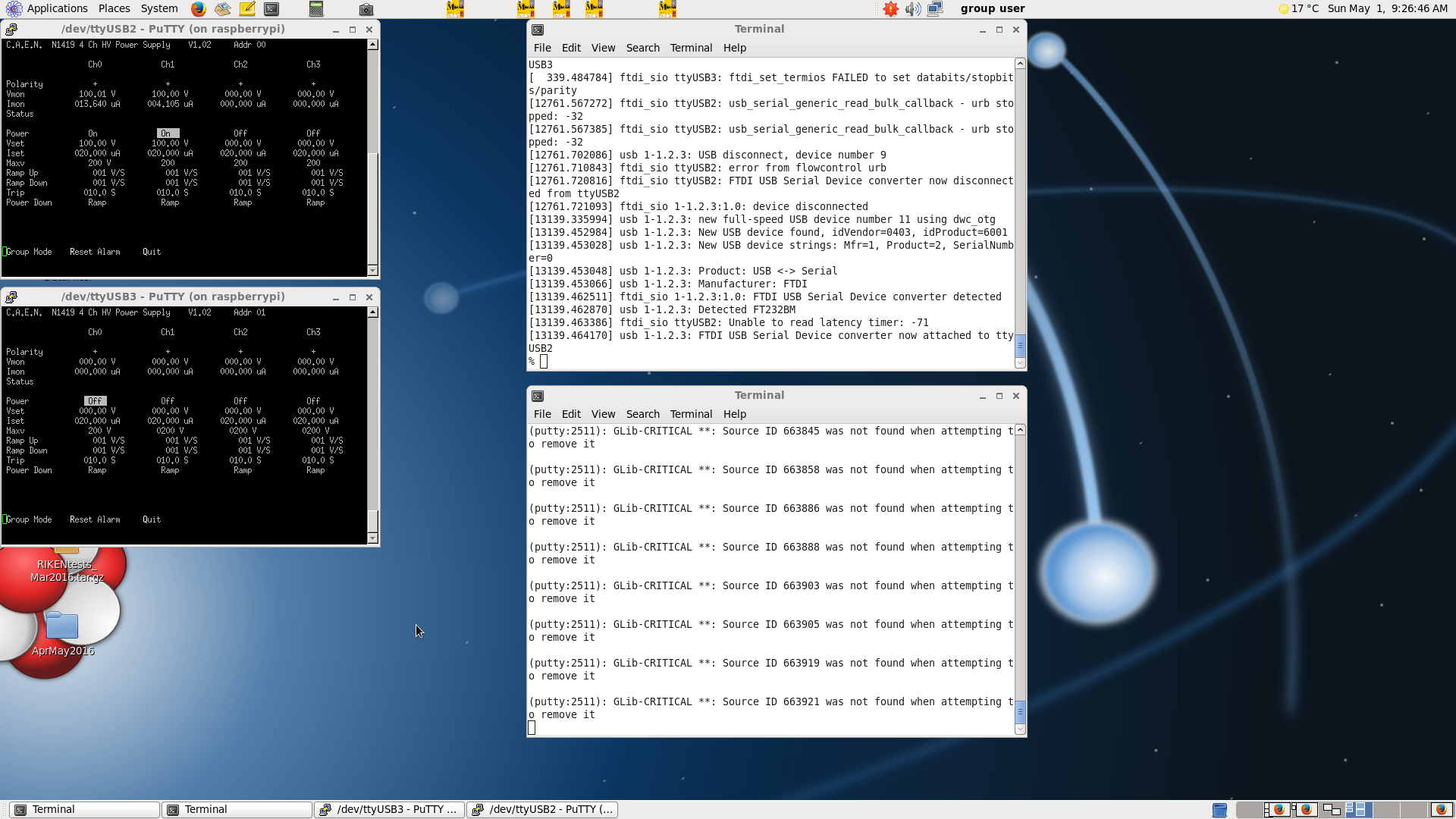
|
|
193
|
Sun May 1 07:59:08 2016 |
CG,PV,TD | AIDA Detector Configuration |
UPSTREAM


Detector  Serial  Operating  CAEN N1519  CAEN N1519  Bias    FEE64                  Bias Config
#         #       Bias (V)   Addr #      channel #   Cable                          Core      Braid

1         3058-2   +100       0           0          1       nnaida25, 27, 30 & 32  nnaida27  nnaida29 (LK5)
2         3058-3   +100       0           1          2       nnaida18, 20, 22 & 23  nnaida20  nnaida22 (LK1)
3         3058-4   +100       0           2          3       nnaida17, 19, 21 & 24  nnaida19  nnaida21 (LK5)
4         3058-5   +100       0           3          4       nnaida10, 12, 14 & 15  nnaida12  nnaida14 (LK1)
5         3058-6   +100       1           0          5       nnaida9, 11, 13 & 16   nnaida11  nnaida13 (LK5)
6         3058-7   +100       1           1          6       nnaida2, 4, 6 & 7      nnaida4   nnaida6 (LK1)
7         2977-15  +100       1           2          7       nnaida1, 3, 5 & 8      nnaida3   nnaida5 (LK5)
8                             1           3          8


DOWNSTREAM

Notes
_____

MSL type BB18 PCB ground links (LK3 & LK7) not fitted

To be checked |
|
197
|
Mon May 2 12:13:25 2016 |
CG,PV,TD | Monday 2 May 2016 |
|
| Attachment 1: 10.png
|
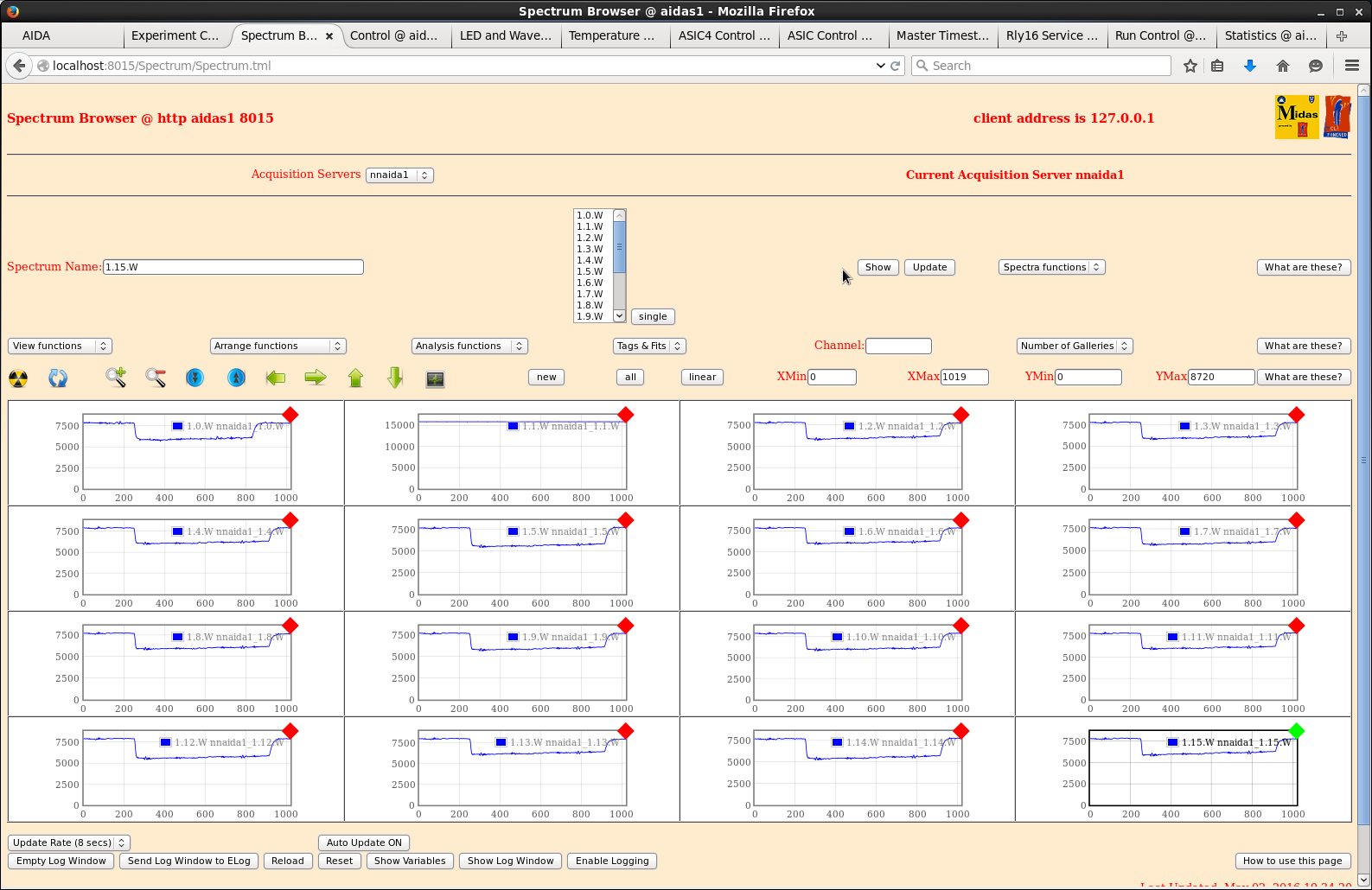
|
| Attachment 2: 11.png
|
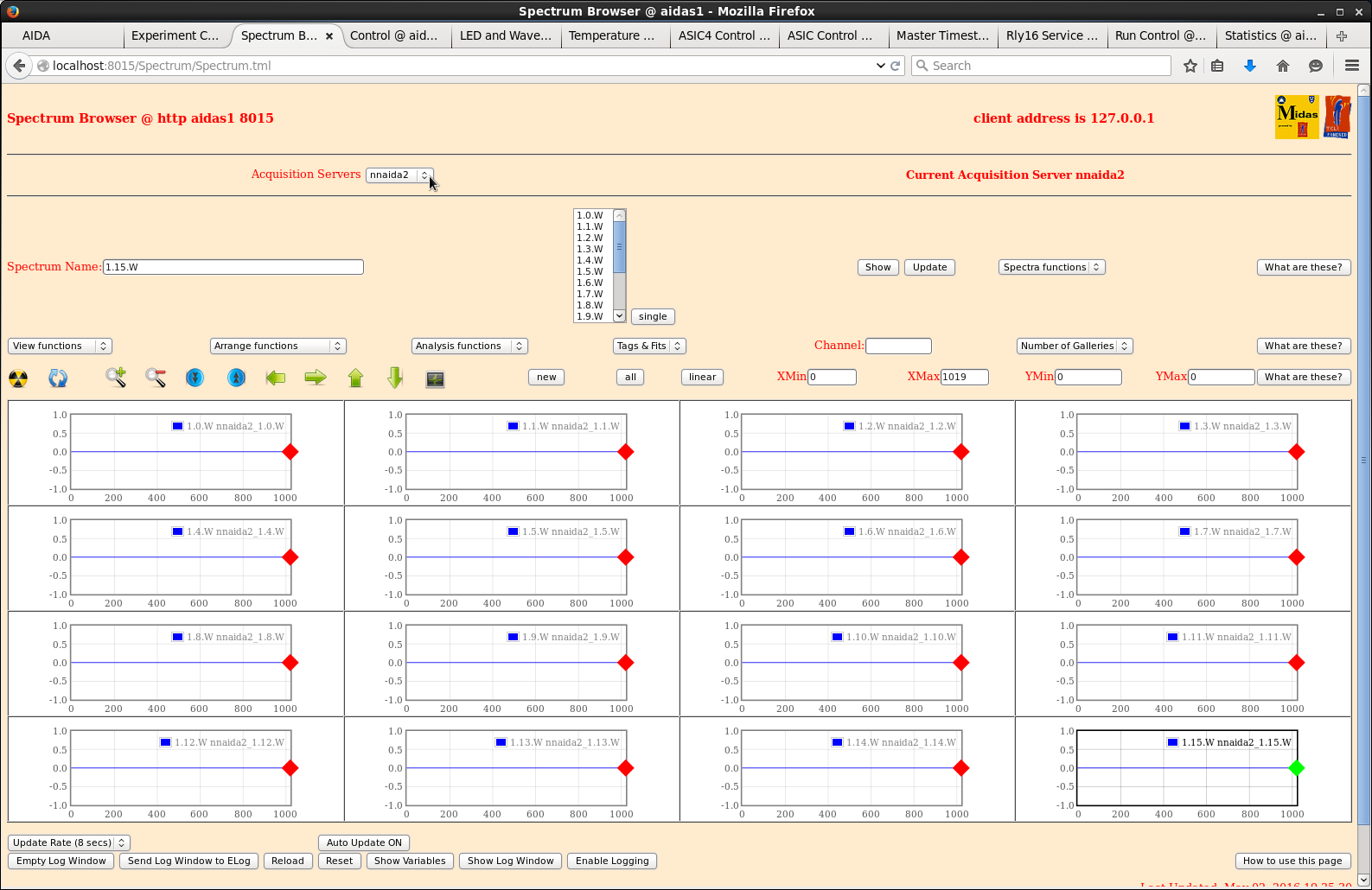
|
| Attachment 3: 12.png
|
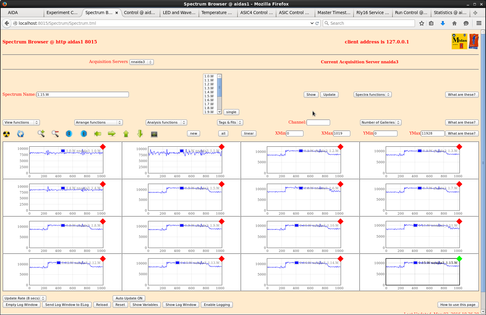
|
| Attachment 4: 13.png
|
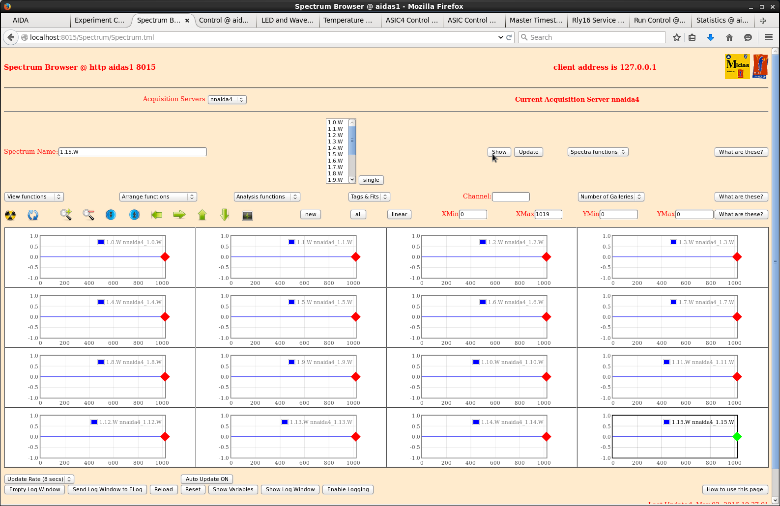
|
| Attachment 5: 14.png
|
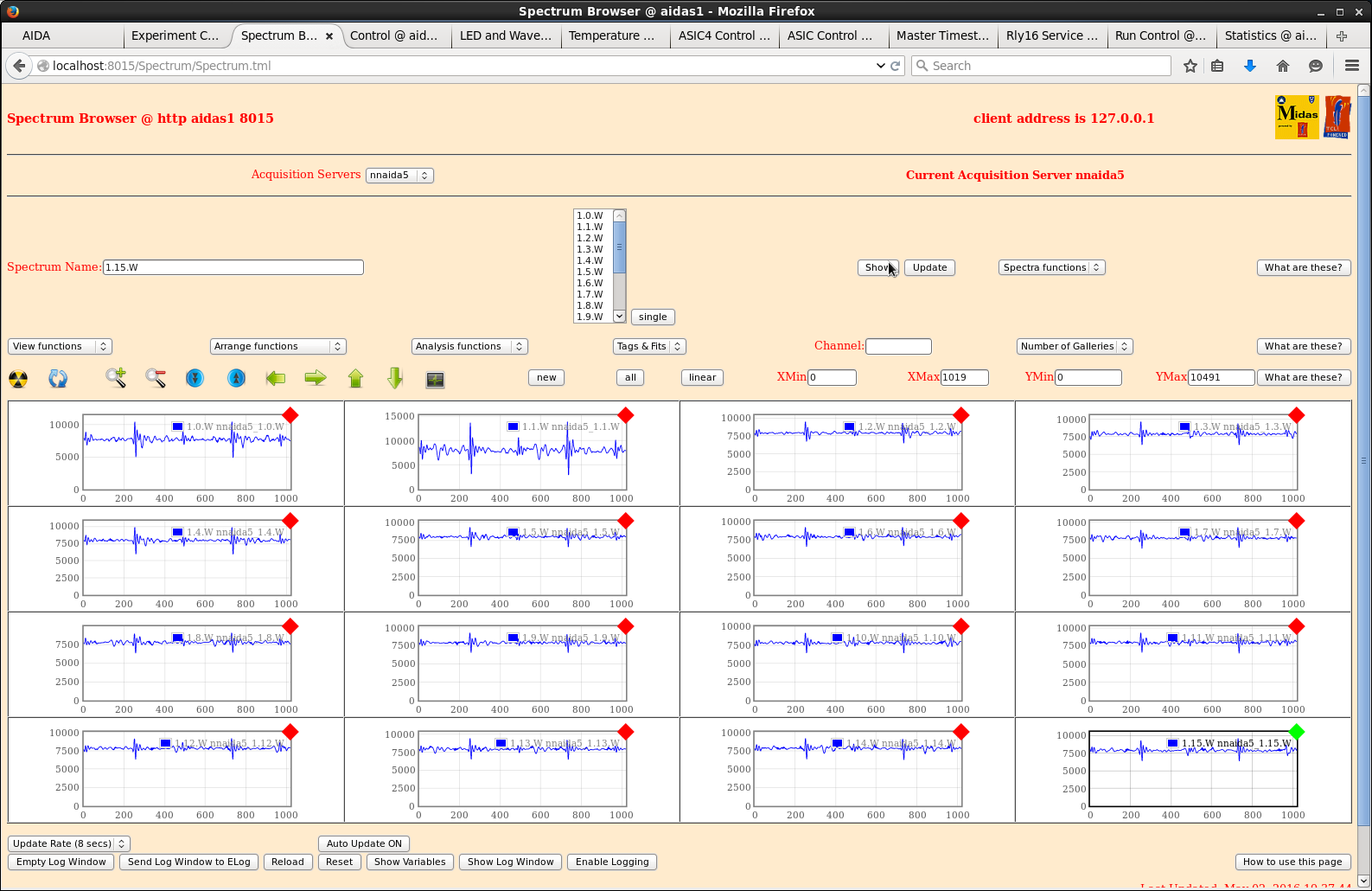
|
| Attachment 6: 15.png
|
|
| Attachment 7: 16.png
|
|
| Attachment 8: 17.png
|
|
| Attachment 9: 18.png
|
|
| Attachment 10: 19.png
|
|
| Attachment 11: 20.png
|
|
| Attachment 12: 21.png
|
|
| Attachment 13: 22.png
|
|
| Attachment 14: 23.png
|
|
| Attachment 15: 24.png
|
|
| Attachment 16: 25.png
|
|
| Attachment 17: 30.png
|
|
| Attachment 18: 31.png
|
|
| Attachment 19: 32.png
|
|
| Attachment 20: 33.png
|
|
| Attachment 21: 34.png
|
|
| Attachment 22: 35.png
|
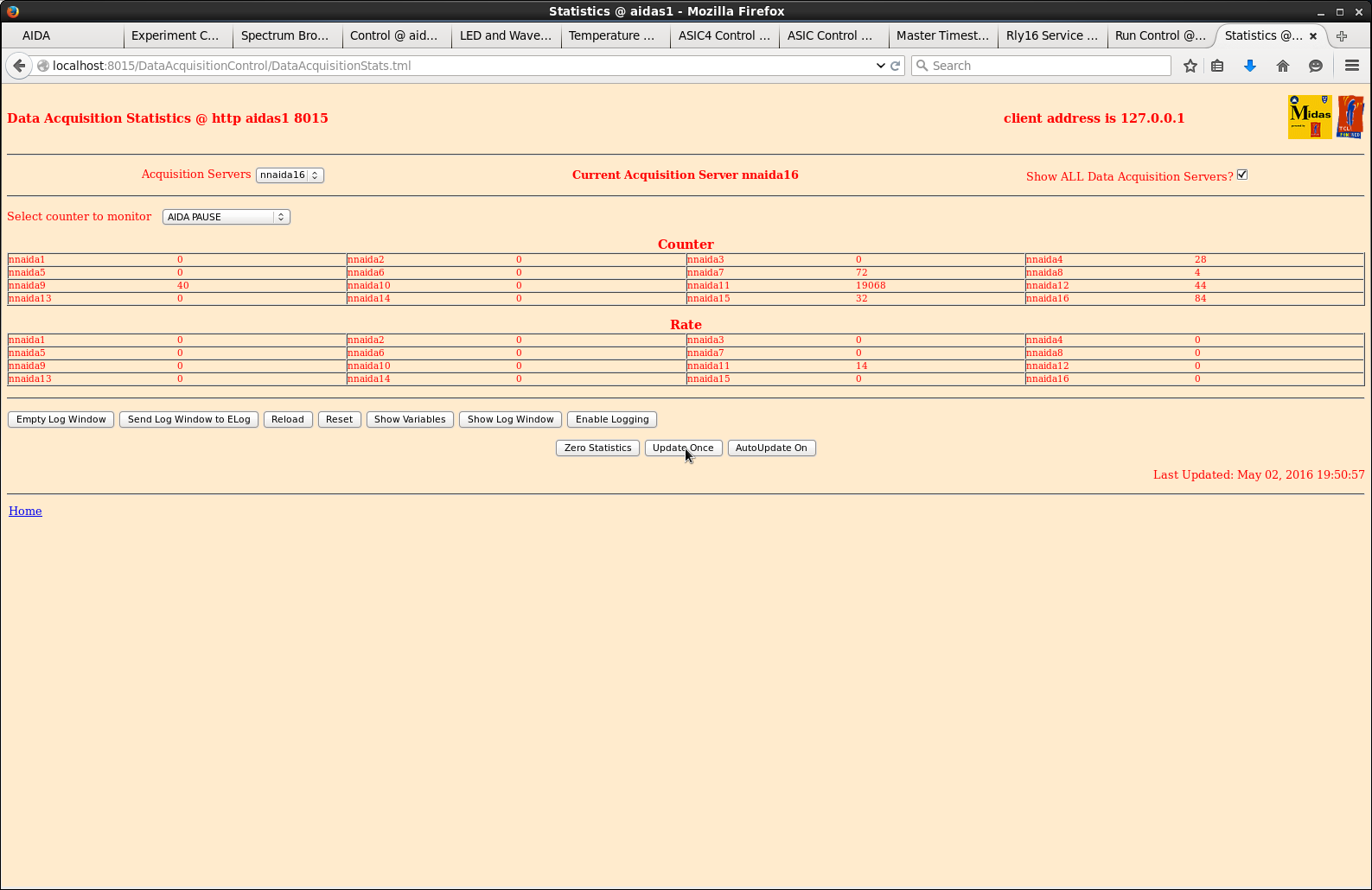
|
|
213
|
Thu May 5 11:10:36 2016 |
CG,PV,TD | Thursday 5 May 2016 |
Detector configuration - see https://elog.ph.ed.ac.uk/AIDA/193

Ribbon cable to nnaida19 FEE adaptor PCB disconnected due to noise issues
associated with nnaida19 or crate slot or power/timestamp/network cabling
to nnaida19 - to be investigated May 22-

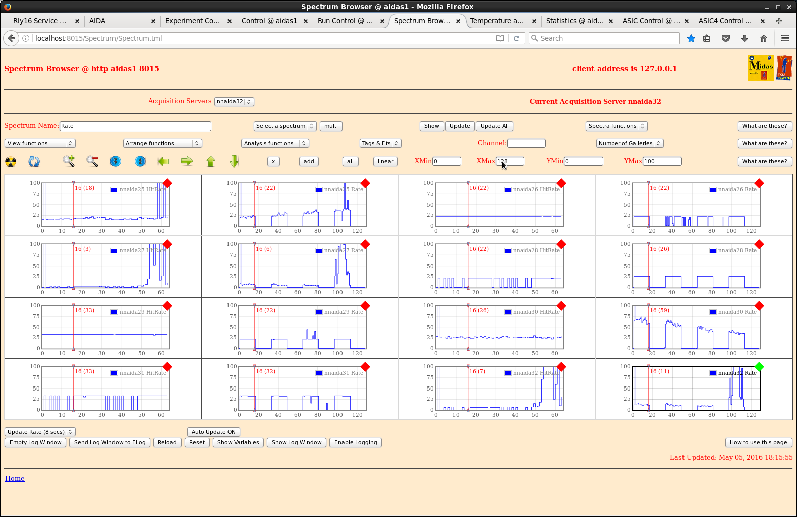
207Bi source ~3cm upstream of DSSSD #1

rate and hit rate spectra for all FEE64s - see attachments 1-4

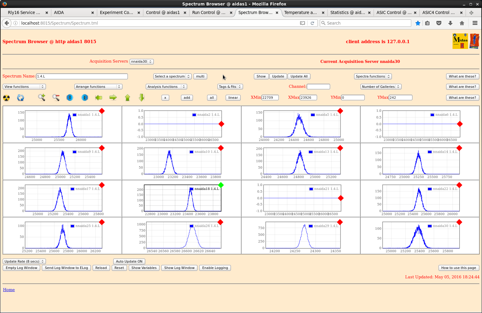
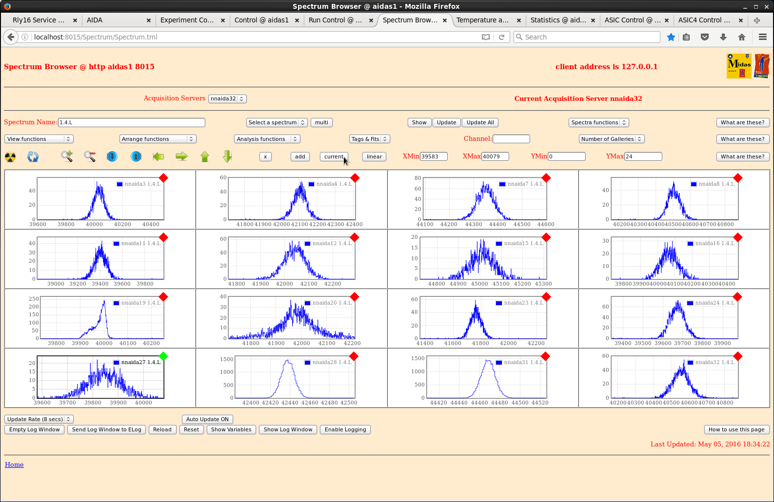
example ADC spectra for all FEE64s - attachment 5 p+n strips, attachment 6 n+n strips

Default ASIC settings, shaping time 8us (which may, or may not, be optimum - to be
investigated May 22- )

      p+n junction strips       n+n ohmic strips
FEE64 Pulser peak width   FEE64 Pulser peak width
      (ch FWHM)                 (ch FWHM)
1     108                 3      88
2      64                 4      84
5     112                 7      76
6       -                 8      85
9      75                 11    122
10     82                 12     98
13     84                 15    127
14     99                 16    115
17     77                 19      ?
18     69                 20    100
21     77                 23     89
22     91                 24     84
25     80                 27    138
26     14                 28     16   } not connected to DSSSD
29     17                 31     17   }
30     130                32    111

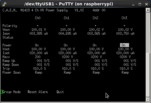
DSSSD bias voltages and leakage currents - attachments 7-8
All bias voltages +100V cf. depletion ~70V for 3058 sequence (MSL type BB18)
Additional bias may be helpful (to be investigated May 22-) |
| Attachment 1: 600.png
|
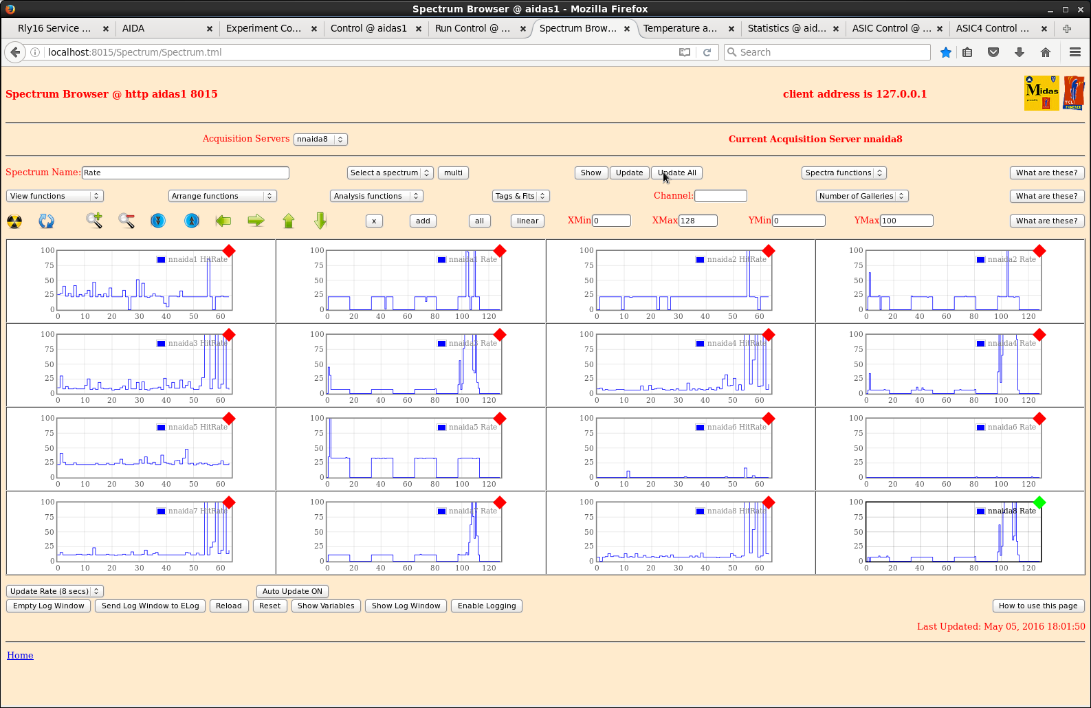
|
| Attachment 2: 601.png
|
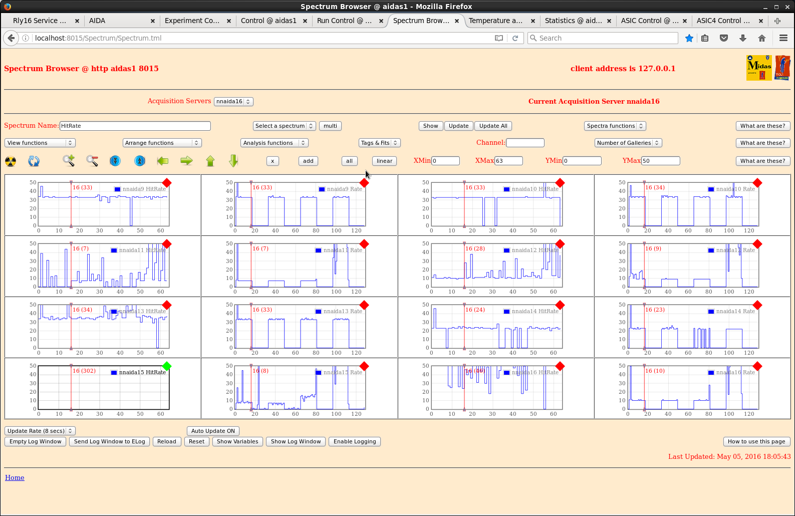
|
| Attachment 3: 602.png
|
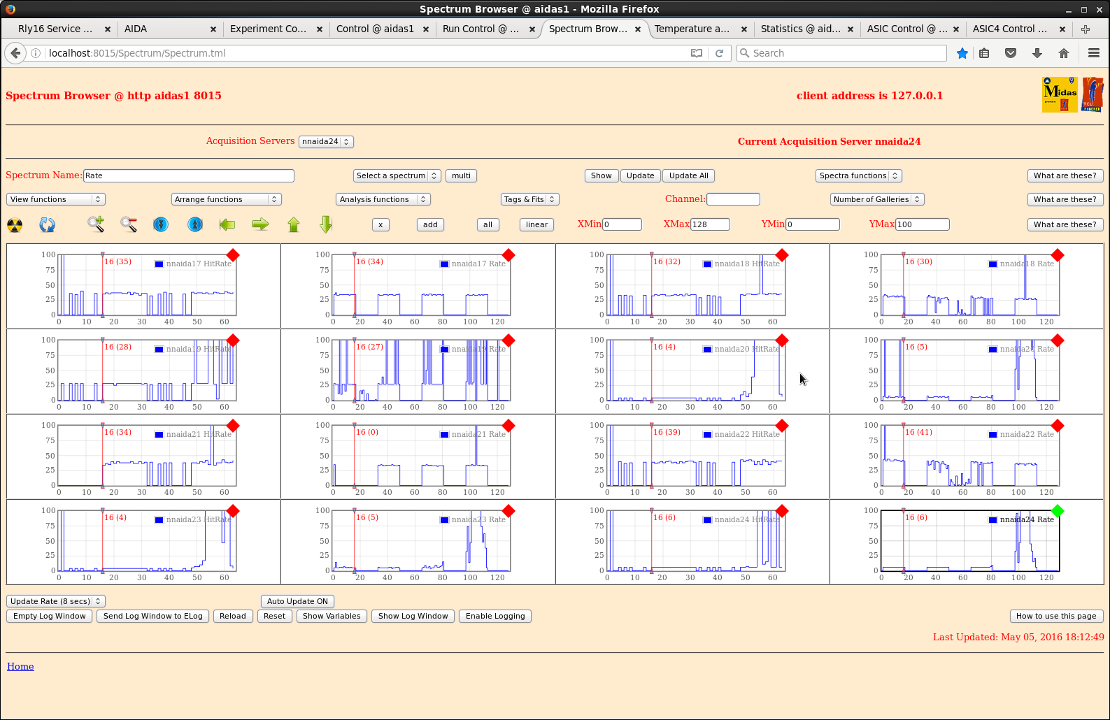
|
| Attachment 4: 603.png
|
|
| Attachment 5: 610.png
|
|
| Attachment 6: 611.png
|
|
| Attachment 7: 620.png
|
|
| Attachment 8: 621.png
|
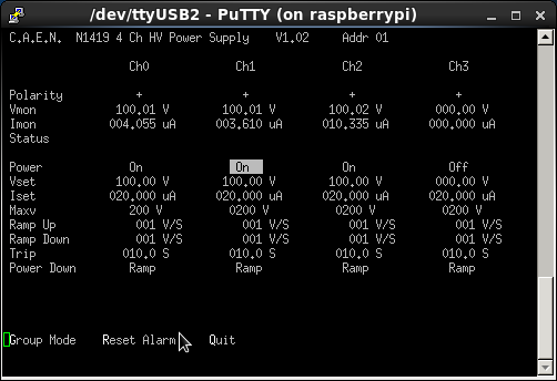
|
|
59
|
Mon Apr 20 09:07:59 2015 |
CG, TD, Patrick Coleman-Smith | Progress 20th April + RPi procedure + reply |
| Quote: |
|
20/04/15
1200: Complete all points on first part of check list, except checking the PSU voltages.
System now in powered and has all network/HDMI cables attached.
1300: Connect RPi to power switch but when powered on it didn't find the switch. A reliable procedure to start seems to be...
- connect USB power switch to RPI, make sure serial cable is disconnected from hub
- power up RPi and power switch
- check connection using dmesg, should see ...FT232RL for USB power switch on USB0
- check connection from aidas1 by pinging RPi inet address 10.1.1.251
- if good, Rly16 page should work from aidas1
- connect serial cable, open PuTTY session, select AIDA console settings, open
- should assign serial cable as USB1 an allow use of both the power switch and FEE console.
Currently this all works, we can control the power switch both from the RPi and aidas1, and see the FEE console via PuTTY session.
1400: Powered on system and tried to set up DAQ but received error (attachment 1) when doing the initial system reset in Run Control.
DAQ still usable for spectrum/temperature viewing, and all FEEs can be accessed to check ASIC control, but it seems timestamping will not be correct.
Tried to perform manual ReSync from master timestamp window and received similar error (attachment 2).
1430: nnaida8 running quite hot (ASIC temp ~65oC) and ASIC temp on nnaida7+15 read as 0.00oC. Otherwise, from pulser/stats data, both seem to be working correctly.
Unplugged power cable for nnaida7+8 at PSU end.
1600: Could timestamping issue originate from MACBs?
In rebuilding AIDA MACB -> FEE cabling redone. Should it follow a particular pattern/tree?
Current tree structure looks like (with MACB numbering going 1->11 L->R as you look at it):
MACB1(setting: 0) ------- out 1: MACB2 (setting: 2) ---------- out 1: MACB3 (setting: 2) -> nnaida3+4, 11+12
---------- out 2: MACB4 (setting: 3) -> nnaida19+20, 27+28
---------- out 3: MACB5 (setting: 3) -> nniada1+2, 9+10
---------- out 4: MACB6 (setting: 3) -> nnaida17+18, 25+26
--------- out 2: MACB7 (setting: 3) ---------- out 1: MACB8 (setting: 3) -> nnaida21+22, 29+30
---------- out 2: MACB9 (setting: 3) -> nnaida7+8, 15+16
---------- out 3: MACB10 (setting: 3) -> nnaida5+6, 13+14 -----> nnaida5 is the master and this comes from output2.
---------- out 4: MACB11 (setting: 3) -> nnaida23+24, 31+32
Patrick - Is this set up OK? Do certain FEEs need to receive the MACB signal from certain MACBs or just all at the same point in the tree?
Also, MACBs 2+3 are on setting 2 on the dial, whereas the others (except MACB1, the 'grandparent') are set to 3. It seems like a hard thing to change accidentally so are they supposed to be like this or should they all be on the same setting?
1630: Voltages to nnaida7+8 OK at PSU output (+6V, +6V, +6V, -6.5V, +8V). Issue with contact to cooling rack?
With pulser input to all FEEs, only see pulser data in spectra for n-side (nnaida3+4, 7+8, 11+12, 15+16) FEEs. Other FEEs all show zero statistics.
|
The MACB system of clock and SYNC pulse distribution does have to follow some rules.
The Master needs to be in a very particular place. The rest are less important as long as they are all at the same level in the tree.
In the tree you report above and using the numbering you report. The Master should be in MACB3:out1.
The settings you have shown are correct if the Master is placed correctly ...
I will input a separate Elog entry detailing the settings for the MACB and the rules for the tree.
Regarding nnaida7+8. I agree the issue to tackle first is the cooling plate contact to the module. Where do they feature in the layout ?
Is the plate tightened up correctly ?
Regarding the P side FEE64s ... sorry about this ... but is the P pulser working ... well i did have to ask ;-)
|
|
60
|
Mon Apr 20 09:38:15 2015 |
CG, TD, Patrick Coleman-Smith | Progress 20th April + RPi procedure + reply |
| Quote: |
|
| Quote: |
|
20/04/15
1200: Complete all points on first part of check list, except checking the PSU voltages.
System now in powered and has all network/HDMI cables attached.
1300: Connect RPi to power switch but when powered on it didn't find the switch. A reliable procedure to start seems to be...
- connect USB power switch to RPI, make sure serial cable is disconnected from hub
- power up RPi and power switch
- check connection using dmesg, should see ...FT232RL for USB power switch on USB0
- check connection from aidas1 by pinging RPi inet address 10.1.1.251
- if good, Rly16 page should work from aidas1
- connect serial cable, open PuTTY session, select AIDA console settings, open
- should assign serial cable as USB1 an allow use of both the power switch and FEE console.
Currently this all works, we can control the power switch both from the RPi and aidas1, and see the FEE console via PuTTY session.
1400: Powered on system and tried to set up DAQ but received error (attachment 1) when doing the initial system reset in Run Control.
DAQ still usable for spectrum/temperature viewing, and all FEEs can be accessed to check ASIC control, but it seems timestamping will not be correct.
Tried to perform manual ReSync from master timestamp window and received similar error (attachment 2).
1430: nnaida8 running quite hot (ASIC temp ~65oC) and ASIC temp on nnaida7+15 read as 0.00oC. Otherwise, from pulser/stats data, both seem to be working correctly.
Unplugged power cable for nnaida7+8 at PSU end.
1600: Could timestamping issue originate from MACBs?
In rebuilding AIDA MACB - > FEE cabling redone. Should it follow a particular pattern/tree?
Current tree structure looks like (with MACB numbering going 1->11 L->R as you look at it):
MACB1 (setting: 0) ------- out 1: MACB2 (setting: 2) ---------- out 1: MACB3 (setting: 2) -> nnaida3+4, 11+12
&nb sp; &nb sp; ---------- out 2: MACB4 (setting: 3) -> nnaida19+20, 27+28
&nb sp; &nb sp; ---------- out 3: MACB5 (setting: 3) -> nniada1+2, 9+10
&nb sp; &nb sp; ---------- out 4: MACB6 (setting: 3) -> nnaida17+18, 25+26
&nb sp; --------- out 2: MACB7 (setting: 3) ---------- out 1: MACB8 (setting: 3) -> nnaida21+22, 29+30
&nb sp; &nb sp; ---------- out 2: MACB9 (setting: 3) -> nnaida7+8, 15+16
&nb sp; &nb sp; ---------- out 3: MACB10 (setting: 3) -> nnaida5+6, 13+14 -----> nnaida5 is the master and this comes from output2.
&nb sp; &nb sp; ---------- out 4: MACB11 (setting: 3) -> nnaida23+24, 31+32
Patrick - Is this set up OK? Do certain FEEs need to receive the MACB signal from certain MACBs or just all at the same point in the tree?
Also, MACBs 2+3 are on setting 2 on the dial, whereas the others (except MACB1, the 'grandparent') are set to 3. It seems like a hard thing to change accidentally so are they supposed to be like this or should they all be on the same setting?
1630: Voltages to nnaida7+8 OK at PSU output (+6V, +6V, +6V, -6.5V, +8V). Issue with contact to cooling rack?
With pulser input to all FEEs, only see pulser data in spectra for n-side (nnaida3+4, 7+8, 11+12, 15+16) FEEs. Other FEEs all show zero statistics.
|
The MACB system of clock and SYNC pulse distribution does have to follow some rules.
The Master needs to be in a very particular place. The rest are less important as long as they are all at the same level in the tree.
In the tree you report above and using the numbering you report. The Master should be in MACB3:out1.
The settings you have shown are correct if the Master is placed correctly ...
I will input a separate Elog entry detailing the settings for the MACB and the rules for the tree.
Thanks
Regarding nnaida7+8. I agree the issue to tackle first is the cooling plate contact to the module. Where do they feature in the layout ?
Is the plate tightened up correctly ?
As far as I am aware this module/crate has not recently been opened so the 'contact' should be as good (or bad) as it ever was.
But it would, of course, bear checking.
Regarding the P side FEE64s ... sorry about this ... but is the P pulser working ... well i did have to ask ;-
According to a DSO the positive and negative pulser inputs and cabling are OK
|
|
|
61
|
Mon Apr 20 09:45:38 2015 |
CG, TD, Patrick Coleman-Smith | Progress 20th April + RPi procedure + reply ++ |
| Quote: |
|
| Quote: |
|
| Quote: |
|
20/04/15
1200: Complete all points on first part of check list, except checking the PSU voltages.
System now in powered and has all network/HDMI cables attached.
1300: Connect RPi to power switch but when powered on it didn't find the switch. A reliable procedure to start seems to be...
- connect USB power switch to RPI, make sure serial cable is disconnected from hub
- power up RPi and power switch
- check connection using dmesg, should see ...FT232RL for USB power switch on USB0
- check connection from aidas1 by pinging RPi inet address 10.1.1.251
- if good, Rly16 page should work from aidas1
- connect serial cable, open PuTTY session, select AIDA console settings, open
- should assign serial cable as USB1 an allow use of both the power switch and FEE console.
Currently this all works, we can control the power switch both from the RPi and aidas1, and see the FEE console via PuTTY session.
1400: Powered on system and tried to set up DAQ but received error (attachment 1) when doing the initial system reset in Run Control.
DAQ still usable for spectrum/temperature viewing, and all FEEs can be accessed to check ASIC control, but it seems timestamping will not be correct.
Tried to perform manual ReSync from master timestamp window and received similar error (attachment 2).
1430: nnaida8 running quite hot (ASIC temp ~65oC) and ASIC temp on nnaida7+15 read as 0.00oC. Otherwise, from pulser/stats data, both seem to be working correctly.
Unplugged power cable for nnaida7+8 at PSU end.
1600: Could timestamping issue originate from MACBs?
In rebuilding AIDA MACB - > FEE cabling redone. Should it follow a particular pattern/tree?
Current tree structure looks like (with MACB numbering going 1->11 L->R as you look at it):
MACB1 (setting: 0) ------- out 1: MACB2 (setting: 2) ---------- out 1: MACB3 (setting: 2) -> nnaida3+4, 11+12
&nb sp; &nb sp; ---------- out 2: MACB4 (setting: 3) -> nnaida19+20, 27+28
&nb sp; &nb sp; ---------- out 3: MACB5 (setting: 3) -> nniada1+2, 9+10
&nb sp; &nb sp; ---------- out 4: MACB6 (setting: 3) -> nnaida17+18, 25+26
&nb sp; --------- out 2: MACB7 (setting: 3) ---------- out 1: MACB8 (setting: 3) -> nnaida21+22, 29+30
&nb sp; &nb sp; ---------- out 2: MACB9 (setting: 3) -> nnaida7+8, 15+16
&nb sp; &nb sp; ---------- out 3: MACB10 (setting: 3) -> nnaida5+6, 13+14 -----> nnaida5 is the master and this comes from output2.
&nb sp; &nb sp; ---------- out 4: MACB11 (setting: 3) -> nnaida23+24, 31+32
Patrick - Is this set up OK? Do certain FEEs need to receive the MACB signal from certain MACBs or just all at the same point in the tree?
Also, MACBs 2+3 are on setting 2 on the dial, whereas the others (except MACB1, the 'grandparent') are set to 3. It seems like a hard thing to change accidentally so are they supposed to be like this or should they all be on the same setting?
1630: Voltages to nnaida7+8 OK at PSU output (+6V, +6V, +6V, -6.5V, +8V). Issue with contact to cooling rack?
With pulser input to all FEEs, only see pulser data in spectra for n-side (nnaida3+4, 7+8, 11+12, 15+16) FEEs. Other FEEs all show zero statistics.
|
The MACB system of clock and SYNC pulse distribution does have to follow some rules.
The Master needs to be in a very particular place. The rest are less important as long as they are all at the same level in the tree.
In the tree you report above and using the numbering you report. The Master should be in MACB3:out1.
The settings you have shown are correct if the Master is placed correctly ...
I will input a separate Elog entry detailing the settings for the MACB and the rules for the tree.
Thanks
Regarding nnaida7+8. I agree the issue to tackle first is the cooling plate contact to the module. Where do they feature in the layout ?
Is the plate tightened up correctly ?
As far as I am aware this module/crate has not recently been opened so the 'contact' should be as good (or bad) as it ever was.
But it would, of course, bear checking.
Regarding the P side FEE64s ... sorry about this ... but is the P pulser working ... well i did have to ask ;-
According to a DSO the positive and negative pulser inputs and cabling are OK
|
|
Regarding the P side problem.
What is the result if you change one of the N-Side FEEs to use the P-side pulser and vice-versa ?
Regarding the temperature problem.
Which position are the problem modules in ? |
|
120
|
Sat Nov 14 20:19:43 2015 |
CG, TD, PJCS | 13 Nov 2015 - new Kapton cable tests at DL |
| Quote: |
|
Powered system up with 4 bare 45cm kaptons connected and nothing seems to have changed from where we left last night
Waveforms in nnaida11 look good and peak widths in nnaida11 1.8.L and 1.10.L are ~70ch.
Turned off flash ADCs for all FEEs by setting Q8_transfer.vhd: 0xa00, offset 0x00, to 0 to assess any affect they may play in the observed noise
no obvious change in peak widths for nnaida11
turned all back on by resetting value of offset 0x00 to 1
Measured RMS deviation of waveform baseline for nnaida11 with 45cm unshielded kapton connected by sampling waveform every 10 samples over 100 samples, i.e. every 200ns for 2us.
1.4.W - mean: 8612.9 st. dev.: 20.5
1.6.W - mean: 8548.9 st. dev.: 16.6
1.8.W - mean: 8900.8 st. dev.: 16.2
1.10.W - mean: 8744.5 st. dev.: 15.0
Removed kapton to check intrinsic RMS deviation of pre-amp using the same method
1.4.W - mean: 8666.8 st. dev.: 4.7
1.6.W - mean: 8586.6 st. dev.: 2.0
1.8.W - mean: 8918.7 st. dev.: 3.2
1.10.W - mean: 8782.3 st. dev.: 4.2
These results are consistent with the pulser peak widths observed with/without Kapton PCBs attached
Make a makeshift screening plate for the adapter PCBs using the Cu tape -> widths in nnaida11 all slightly worse but still comparable.
Connected detector using 4 45cm kaptons (gnd via nnaida13) and baised via nnaida12+13 to +200V with a leakage current of 5.16uA (Room temp 24.2oC)
Initially observed very noisy waveforms but grounding adapter PCBs together improved the noise slightly but not to an acceptable level (see attachment 2+3).
Measure the peak width as a function of shaping time:
t_shape: 0.5 | 1.0 | 2.0 | 4.0 | 8.0
FWHM (ch): 308 | 352 | 345 | 252 | 130
Throughout, the peaks were non-Gaussian and double peaked with single peak widths ~50-70ch.
Pickup effect rather than white noise?
Shielded kapton to nnaida11 with Cu tape and found noise to decrease slightly when grounded to LEMO connector on adapter PCB - bursts reduced in amplitude but persistent periodic noise remained (see attachments 4+5).
Changed grounding around (adapters to NIM crate, adapters to detector box etc) and observed no noticeable difference.
However, removing jumpers grounding PCBs to FEE cards and the grounding between the adapter PCBs makes the noise worse.
Shielded 3 more 45cm kaptons and connected detector -> no leakage current.
Found several pins on 2 kaptons to be broken. Will get these fixed in Edinburgh for use next week.
Reconnected old kaptons and system is as expected - slower rise time in waveforms but reasonable levels of noise and expected peak widths (see attachment 6).
|
To power down the ADCs the register to be loaded with 0xFF is in the "Local Registers" window.
What you did was to disable the readout of the ADCs which doesn't change the level of activity or reduce the power.
|
|
126
|
Wed Nov 25 19:24:39 2015 |
CG, TD, PJCS | New Kapton cable tests at DL |
Powered system on and biased to +200V at room temp of 22.4oC. Leakage current of 3.37uA.
Waveforms very noisy and spectra dominated by low E noise. Upon taking a close look at front end found one of the kaptons to have broken a connection. Swapped it out for a spare.
Returned to same situation as last week. Peaks all have a shoulder at t_shape of 8us, but main peak has width ~80ch. Shorter shaping times lead to double peaking.
Removed FEEs from crate and properly seated adapter PCBs on Cu mounting block, with washers between plated part of PCB and allen screw.
- <0.4 ohm impedance betwee Cu mount block and washer/screw but ~20 ohms between screw and LEMO connector => 20 ohms between Cu mounting block and LEMO connectors
- plating around screw holes doesn't go anywhere.
Confirmed LEMOs are connected to ASIC ground (as they should be) on the Cu mezzanine block with <0.2 ohm impedance between mezzanine Cu and LEMO connectors.
With adapter PCBs removed, Cu mezzanine blocks of separate modules still have impedance < 0.3 ohm between them. How/why?
- found out MACB cables, power cables and network cables all connect the grounds of each FEE card/module. Was this expected? Does this cause us problems?
Swapped non-functioning nnaida12 for the former nnaida11 from the module featuring the other broken nnaida12 - all seems to work, although no waveforms are produced.
Very low impedance between ASIC grounds of FEE cards in same module.
To obtain a better ground connection between the ASIC grounds of separate modules, connected a thick braid to Cu mezzanine block of each. Operating at limit of multimeter so no noticeable difference in impedance. But...
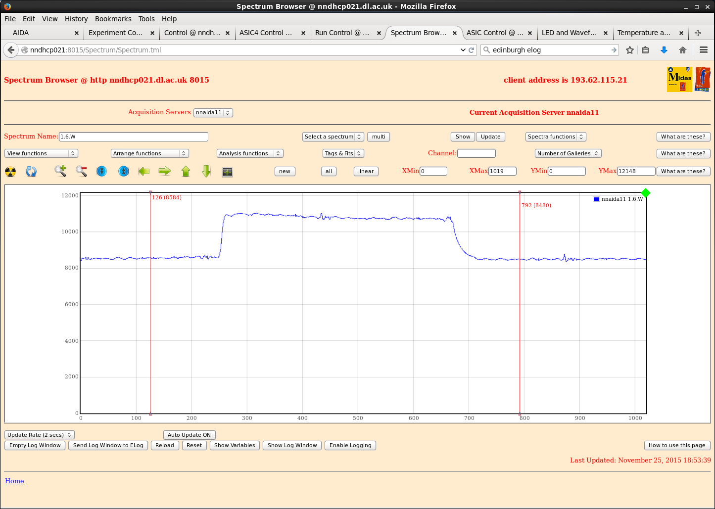
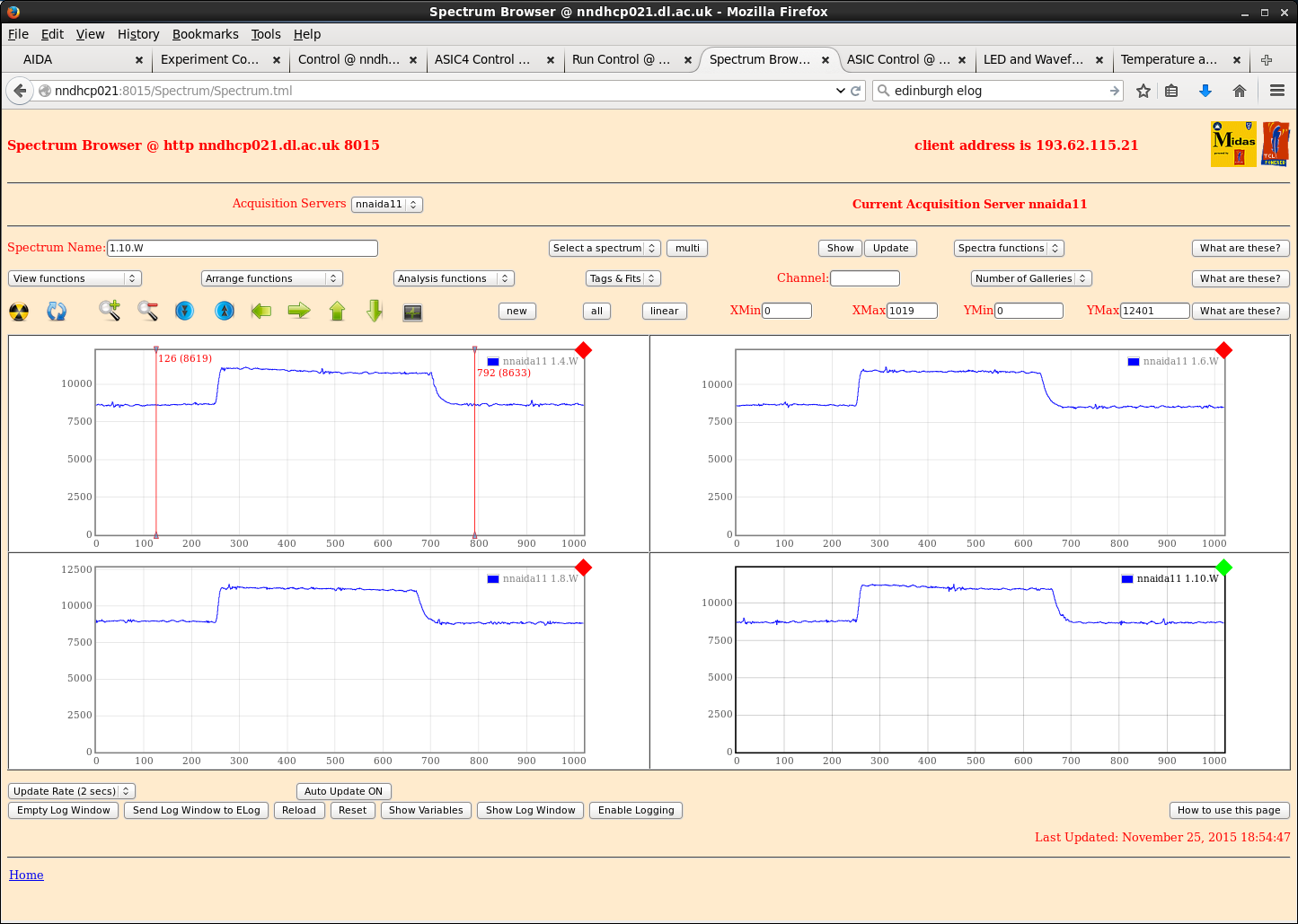
With mezzanines connected and thick braid connecting HV and pulser at LEMO connectors, see the best waveforms so far; very little noise, some transients (attachments 1+2).
However, in nnaida14 waveform does not get back to baseline properly after a pulser event (attachments 2+3).
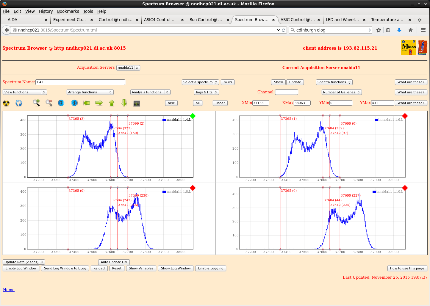
Despite very clean waveforms, still see double-peaking in spectra, although peak widths are fairly low (attachment 6).
|
| Attachment 1: nnaida11_wav_mezzConnectedPlusThickBraid.png
|
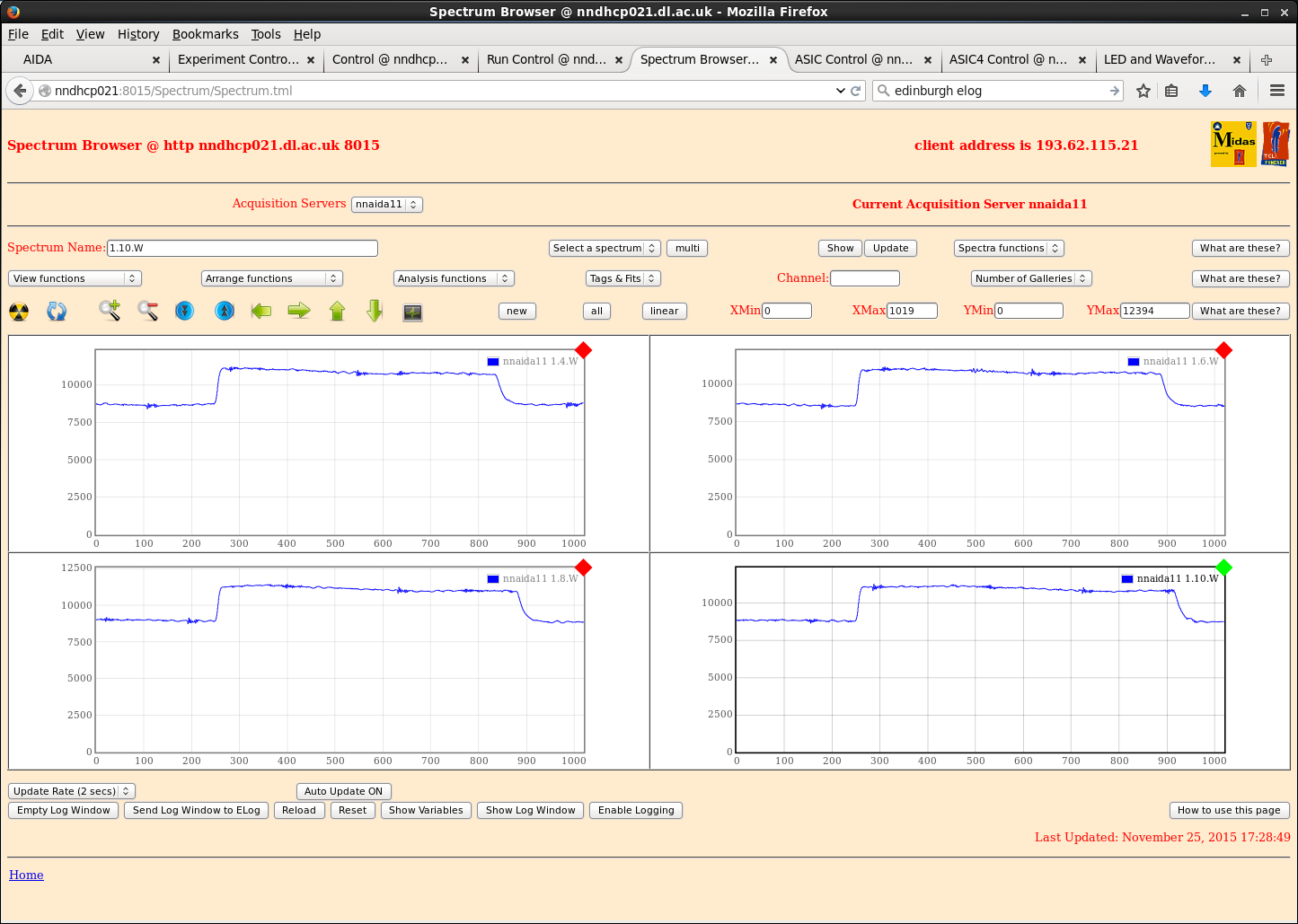
|
| Attachment 2: nnaida14_wav_mezzConnectedPlusThickBraid.png
|
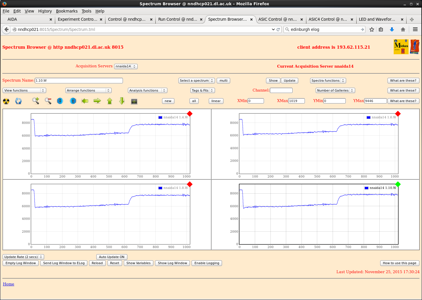
|
| Attachment 3: nnaida14_wav_resetDiff.png
|
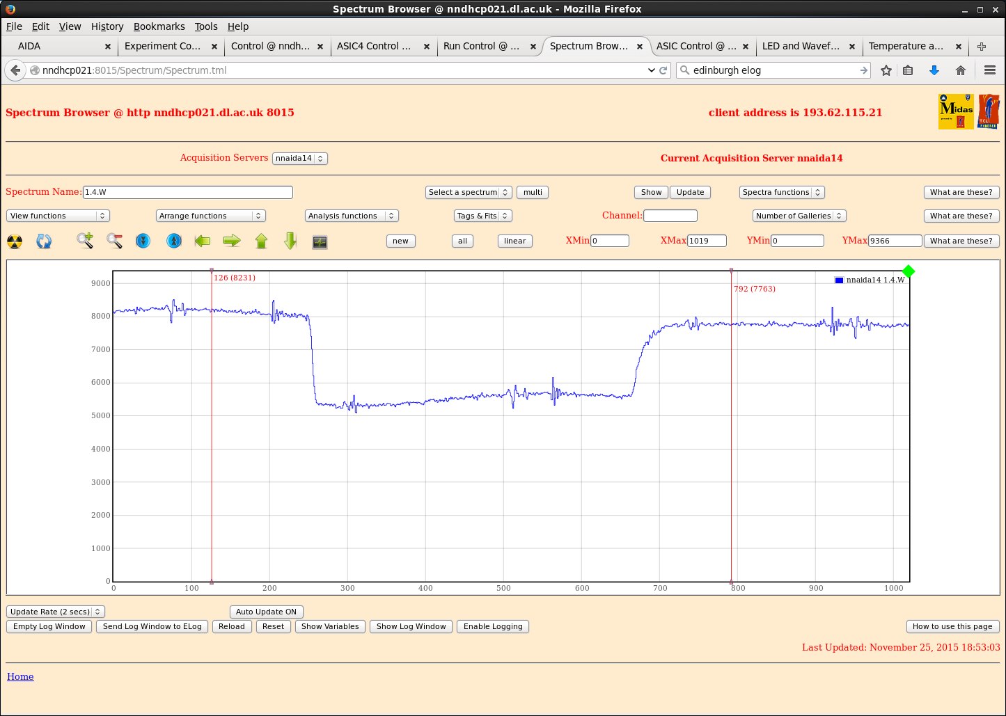
|
| Attachment 4: nnaida11_wav.png
|
|
| Attachment 5: nnaida1_wav_multi.png
|
|
| Attachment 6: nnaida11_spec4us.png
|
|
|
137
|
Wed Jan 6 16:06:32 2016 |
CG, TD, PJCS | Report: Low - RPi power cable can't be fully inserted due to case conflict - solved |
| Quote: |
|
The RPi power cable cannot sit fully in the connector, and the lock pins can't engage, because the case gets in the way of the plastic around the end.
As a result we have knocked it out a couple of times and lost power to the system.
Can this be modified or can we get a new case/cable that resolves this issue?
|
The case has been changed for one that doesn't allow the power cable to be easily extracted. |
|
423
|
Sat Nov 5 01:55:15 2016 |
CG, TD, OH | Saturday 5th November |
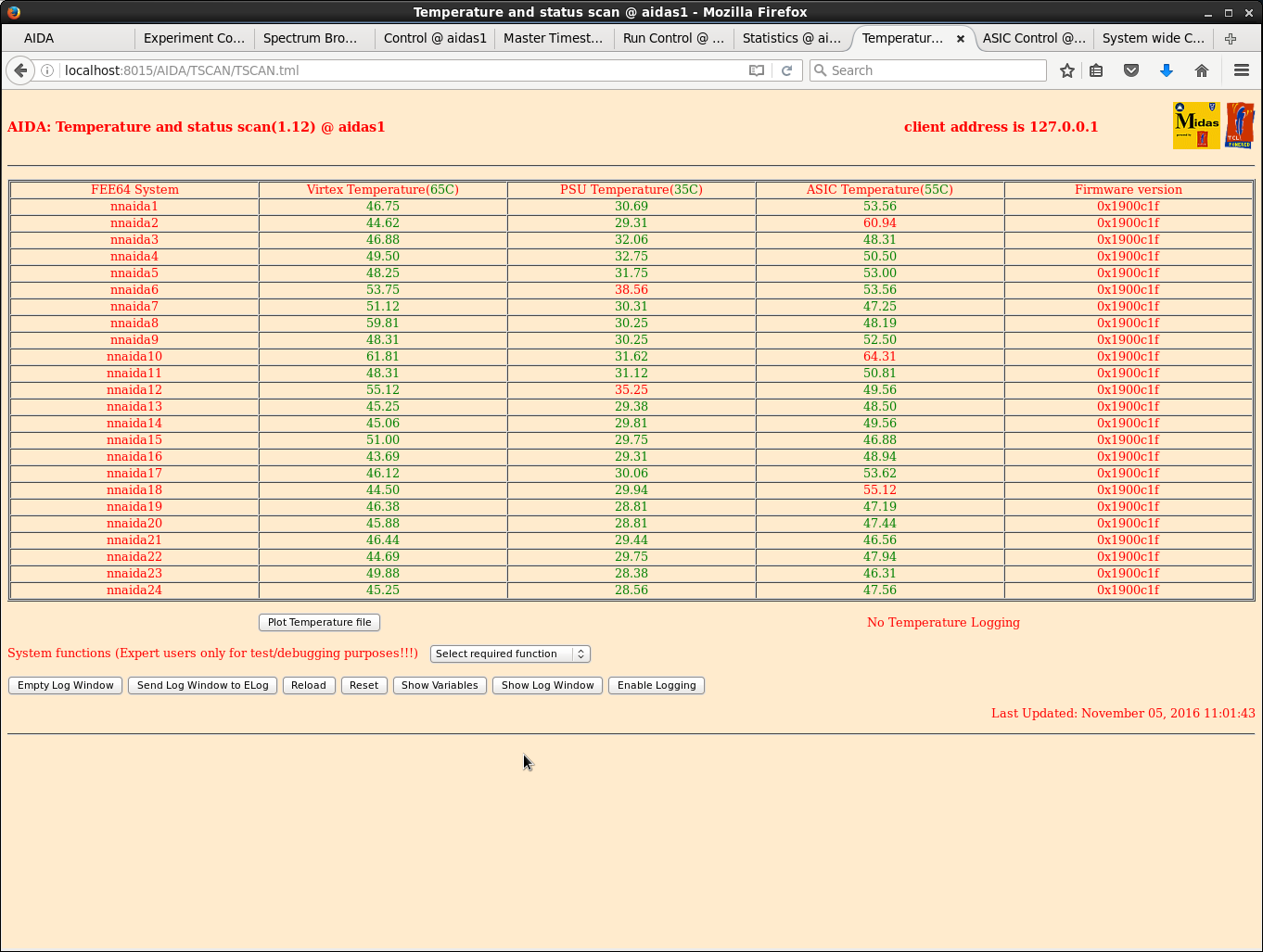
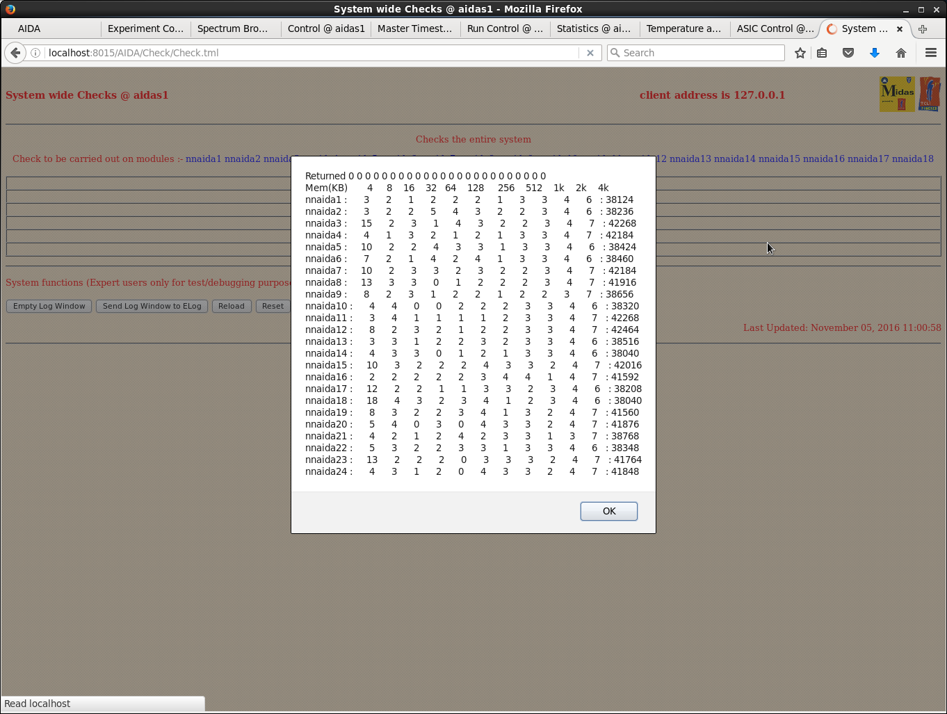
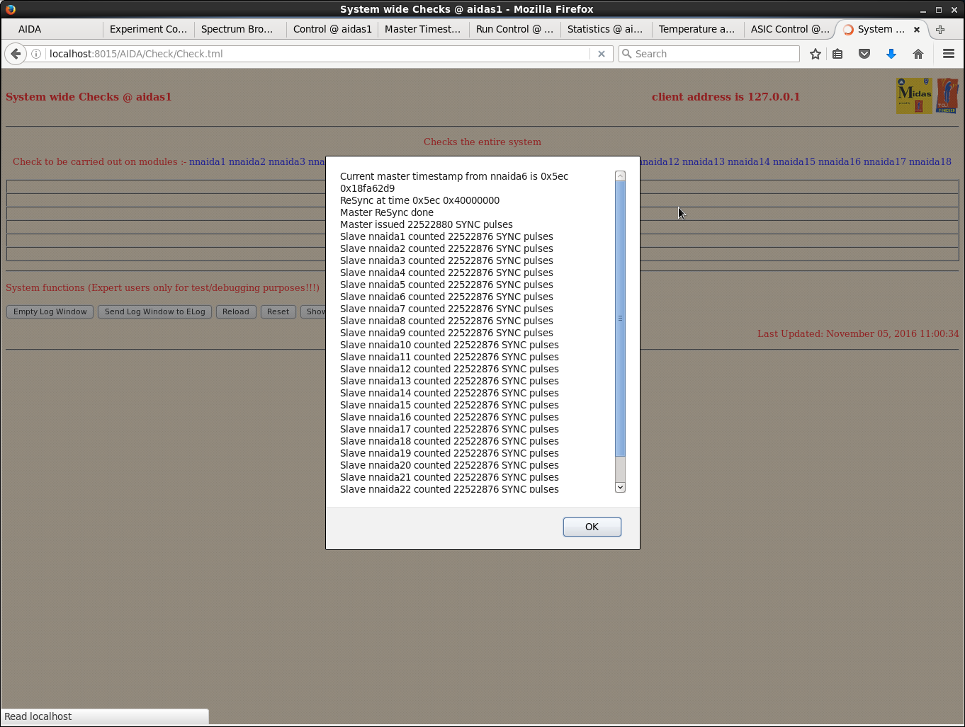
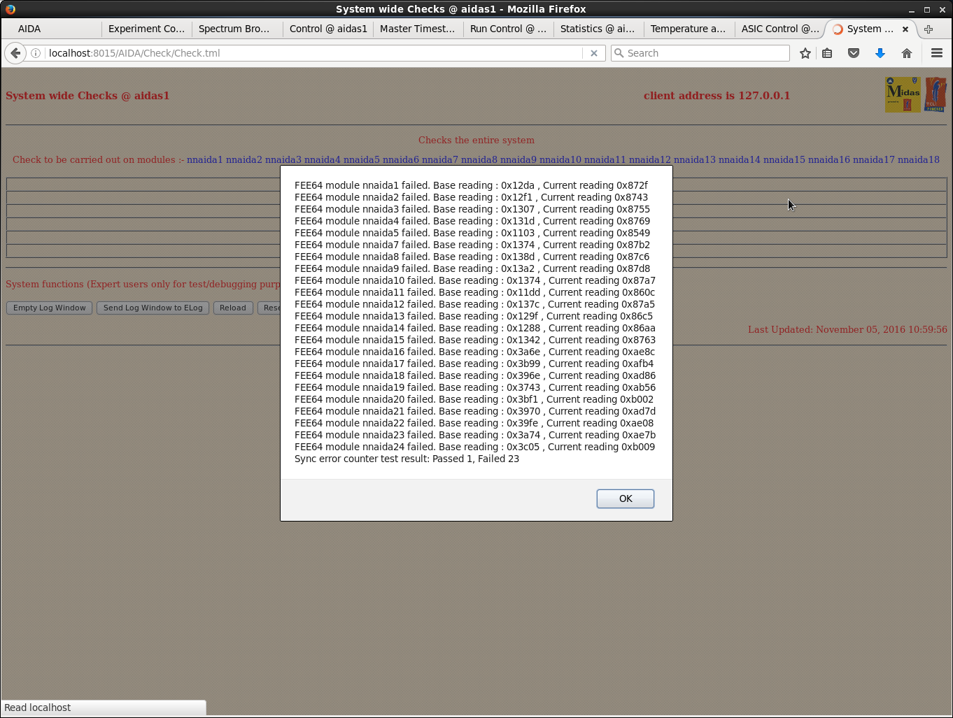
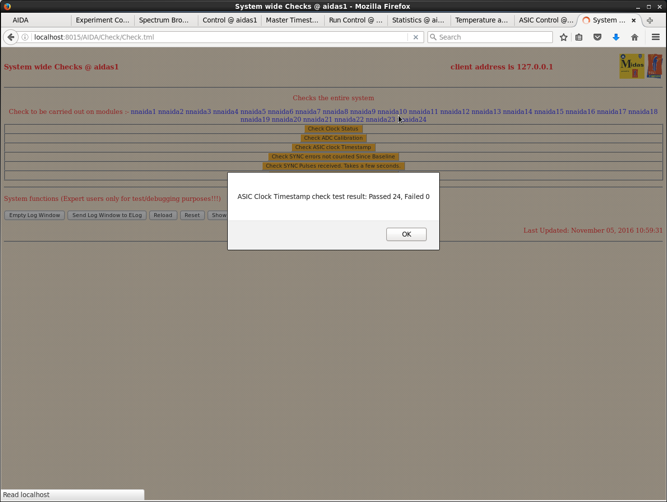
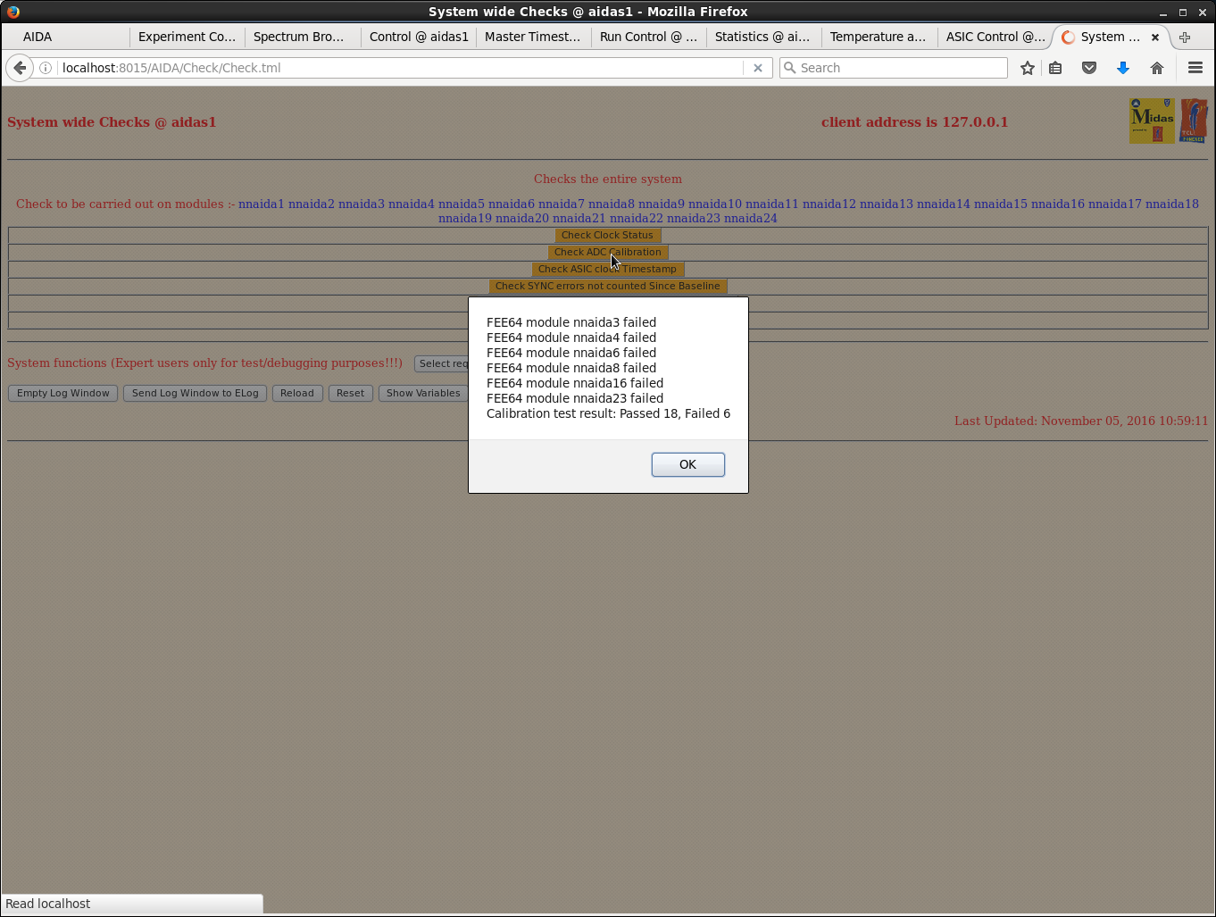
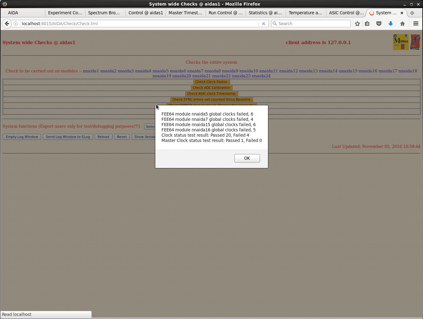
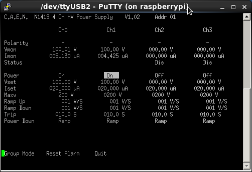
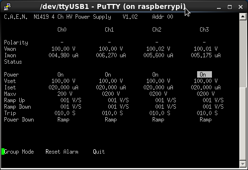
10.55 DAQ found to have stopped at 06:47 during LN fill cycle.

10:57 Screen shots of system after stop

11.20 R122 started.
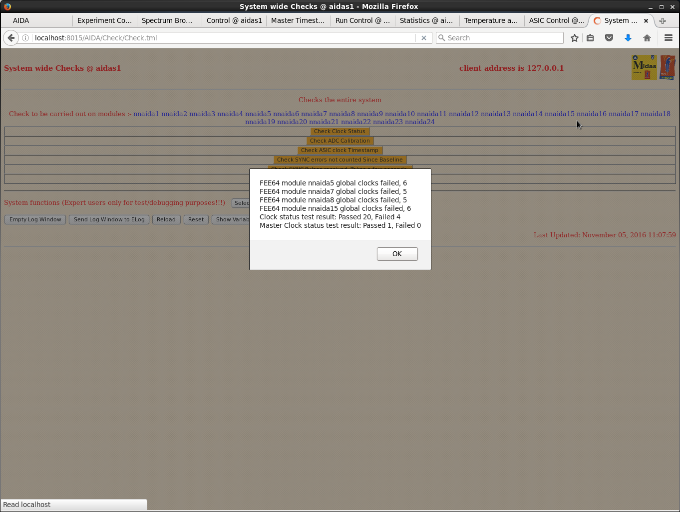
      System check screen shots attached at 11:08

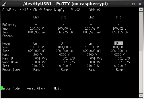
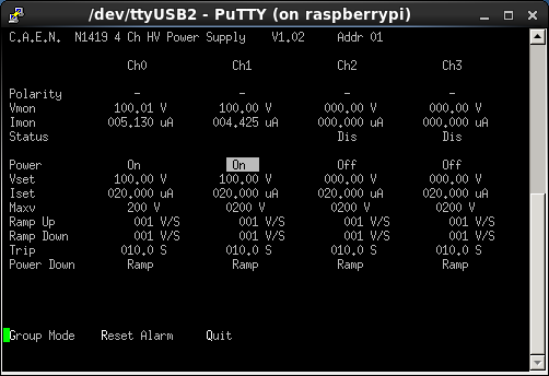
18.20 System been running stably all day. Leakage currents attachments 14+15.
      LN2 fill cycle shortly, anticipate DAQ stop.

19.16 DAQ stopped.
      Closed file R122.

19.37 Temp 25.3 DP 6.1 Hum 31.1
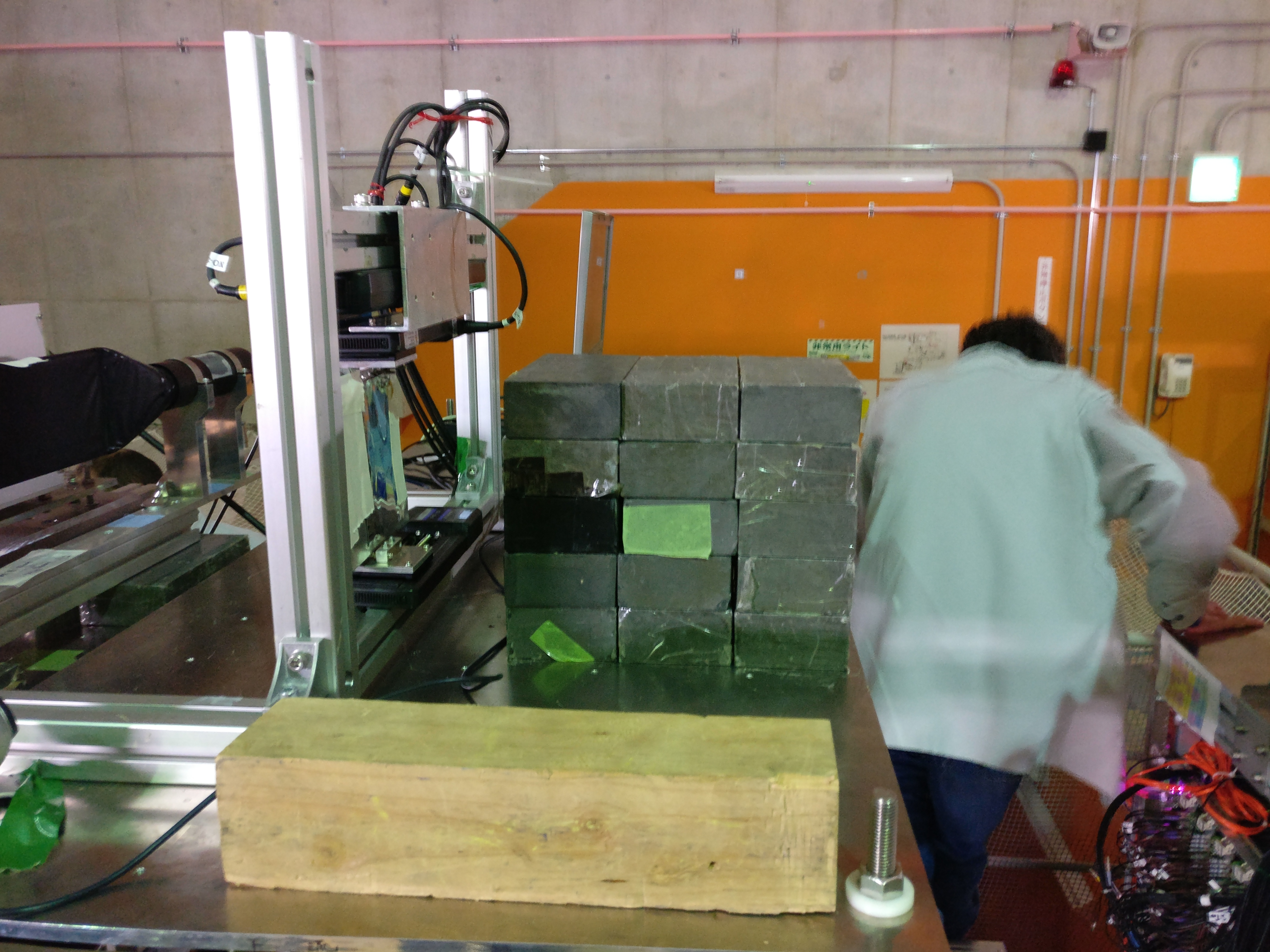
      Added 2 extra stacks of lead bricks to protect AIDA. Now ~15cm of lead (Attachment 17)

23.30 DSSSD bias & leakage currents OK - see attachments 18-19
      FEE74 temperatures OK - see attachment 20

23.54 DAQ starts (R124)
      Merge rate 1.8M items/s, c. 13Mb/s to disk c. x2 earlier rates
      Dominated by significantly higher rates from DSSSD#1
      FEE64 #17 ASIC 2*L pulser peak widths ~300 ch FWHM
Needs to be investigated at next entry opportunity |
| Attachment 1: temp_1057.png
|
|
| Attachment 2: FEE64_Memory_1057.png
|
|
| Attachment 3: SYNC_puls_1057.png
|
|
| Attachment 4: asic_SYNC_1057.png
|
|
| Attachment 5: asic_timestamp_1057.png
|
|
| Attachment 6: adc_calibration_1057.png
|
|
| Attachment 7: clock_status.png
|
|
| Attachment 8: bias2_10_57.png
|
|
| Attachment 9: bias1_10_57.png
|
|
| Attachment 10: feee_mem_1108.png
|
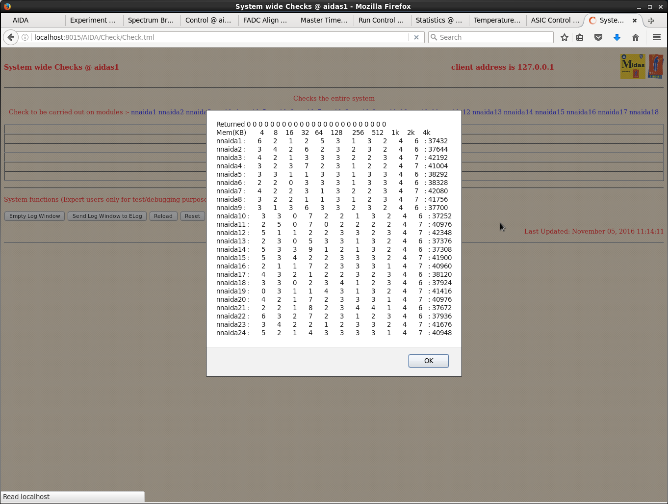
|
| Attachment 11: sync_pulses_1008.png
|
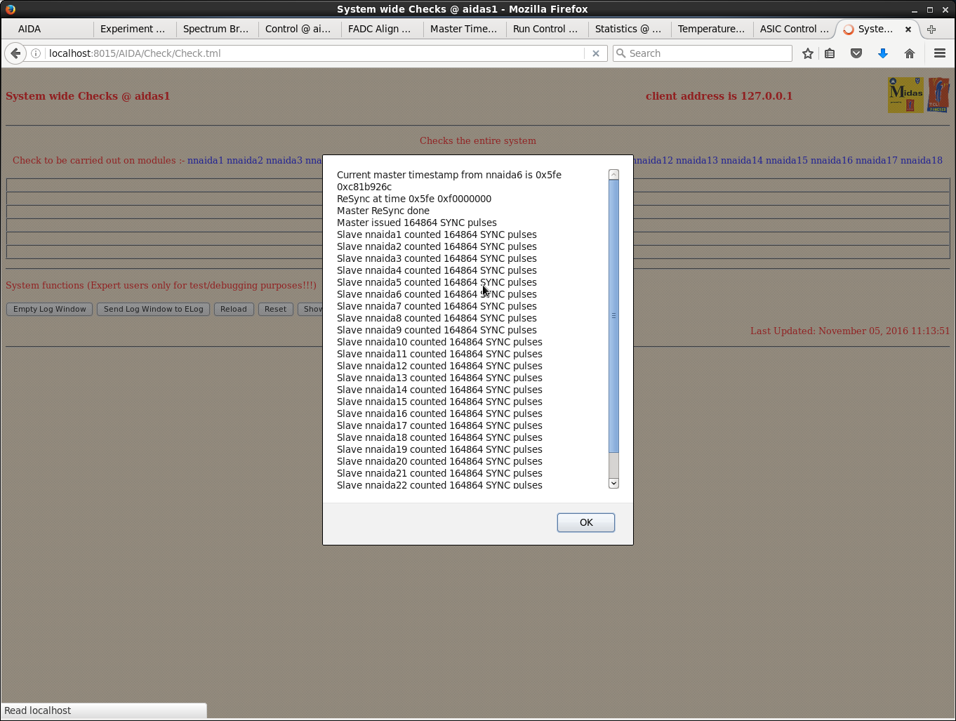
|
| Attachment 12: sync_baseline_1108.png
|
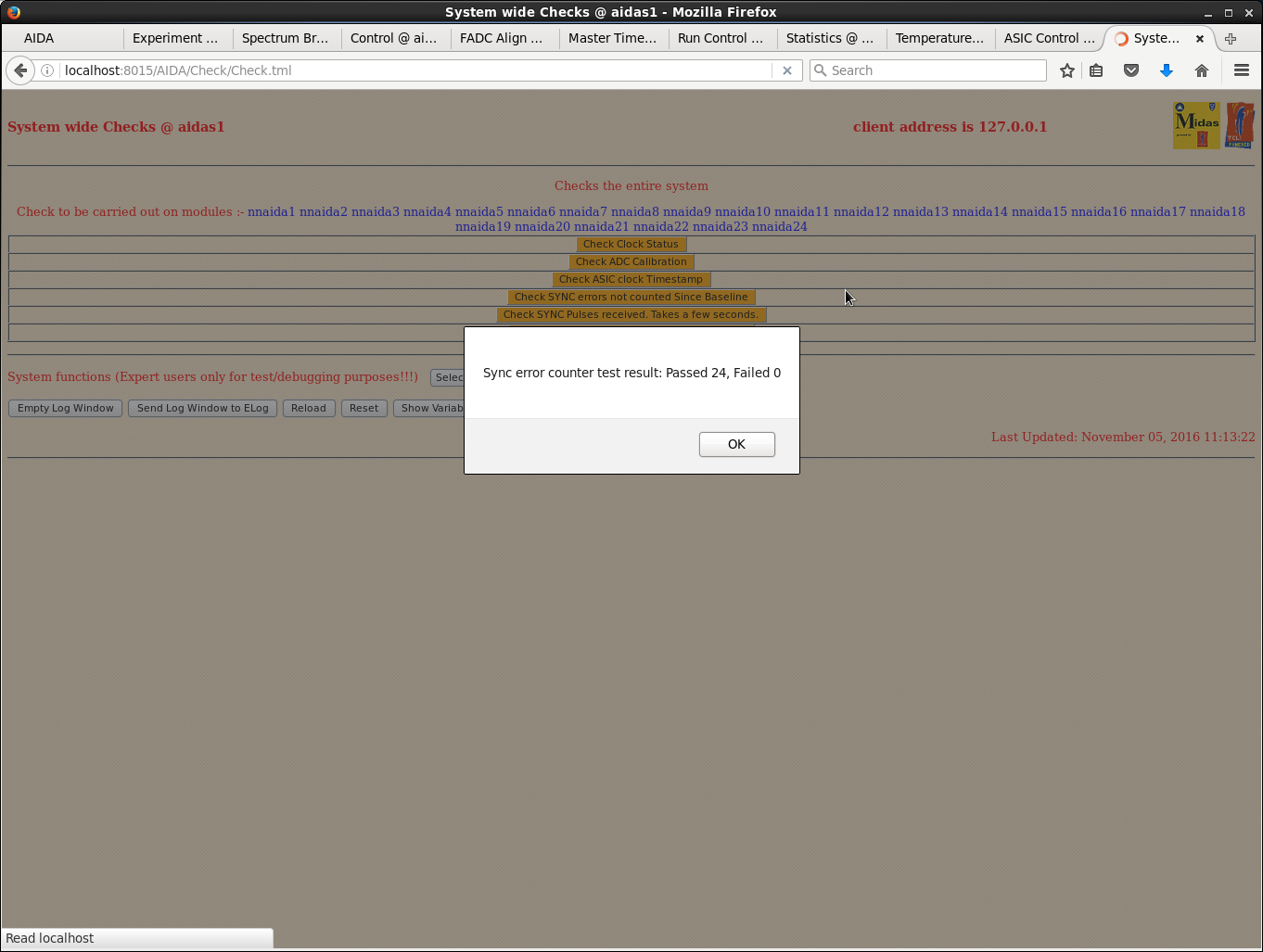
|
| Attachment 13: adc_calib_1108.png
|
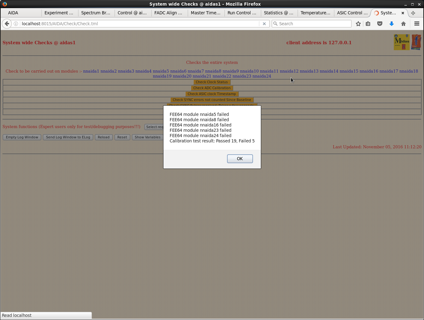
|
| Attachment 14: clock_status_1108.png
|
|
| Attachment 15: bias_1820.png
|
|
| Attachment 16: bias2_1820.png
|
|
| Attachment 17: 2016-11-05_19.31.44.jpg
|
|
| Attachment 18: 1.png
|

|
| Attachment 19: 2.png
|

|
| Attachment 20: 3.png
|

|
|
436
|
Tue Nov 8 15:10:16 2016 |
CG, TD, DK, OH | NP1412 R5 R6 |
00.15 Setting changed to 71,72,73Ni. All variable degraders in.
      Will remove while watching rates to settle on degrader setting.
      F5 CH2 in. F7 CH2 out. F11 C target in.
      F11 plastic rate 1.2kHz.
      R5 started.

00.30 Cut F2 momentum slit. F11 plastic rate down to ~400cps.

00.34 Increased primary beam intensity by x2.
      F11 plastic rate increased to ~800cps.
      This setting should run until the beam change ~03.00.

00.47 R6 started.
      All degraders gradually removed but implant rate in DSSD1 only ~10s Hz.

01.03 71,72,73Ni beam stopped for tuning to next setting.
      R6 stopped.
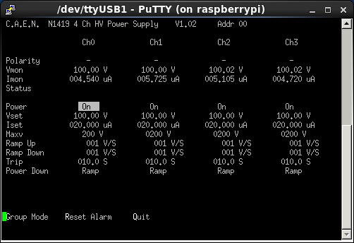
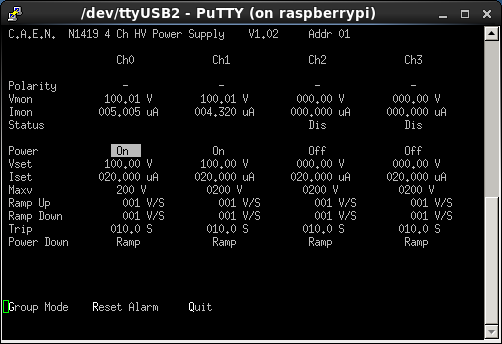
Leakage currents attachments 1+2 |
| Attachment 1: bias1.png
|
|
| Attachment 2: bias2.png
|
|
|
291
|
Tue Jun 7 19:19:34 2016 |
CG, TD, DK, AE | Wednesday 8th June |
(4 mm Al mask was put upstream of AIDA near 20:20 on 7 June)
01.15 Run R1219 started on neutron rich setting.
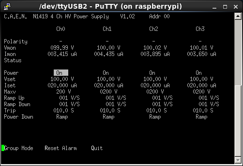
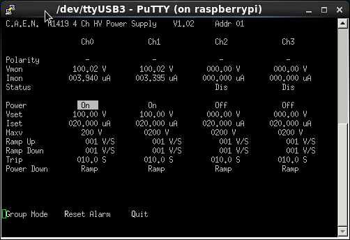
Temps ok. Leakage currents ok.
Plate with holes in front of AIDA , after F11 plastic. F11 plastic count rate ~700cps.
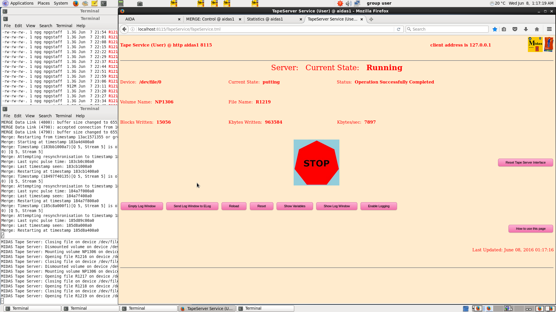
Keeps getting 'Attempting resychronisation' message in merger terminal window.
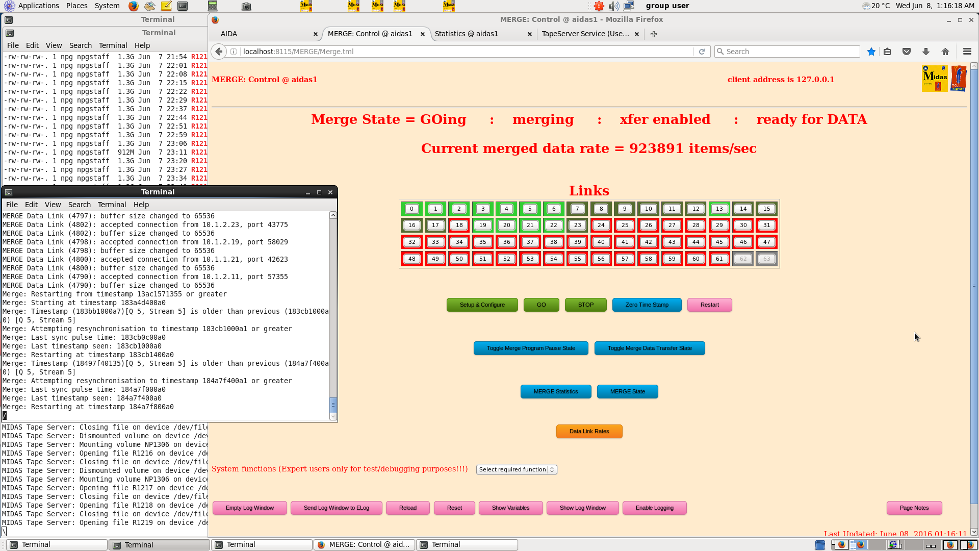
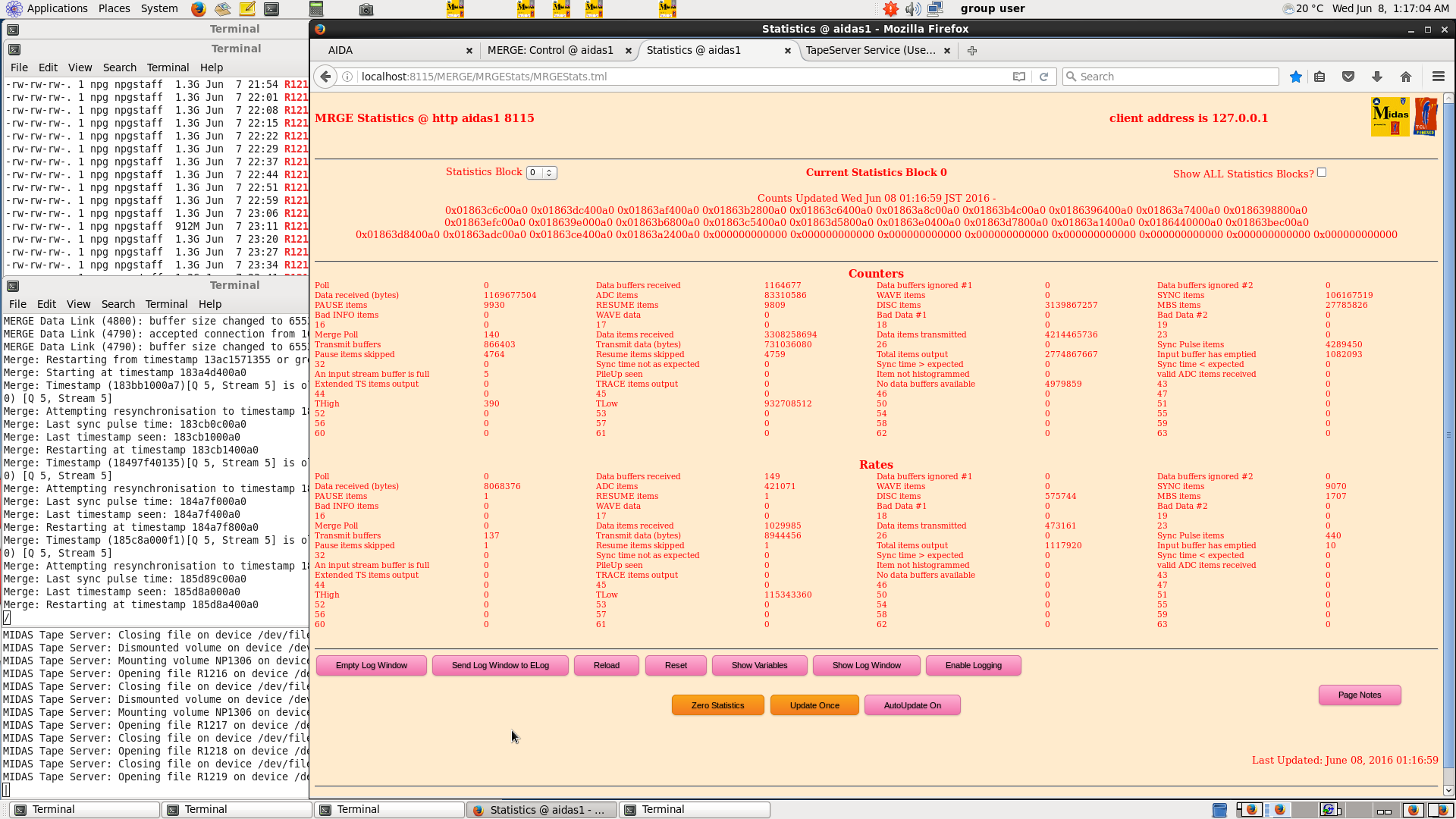
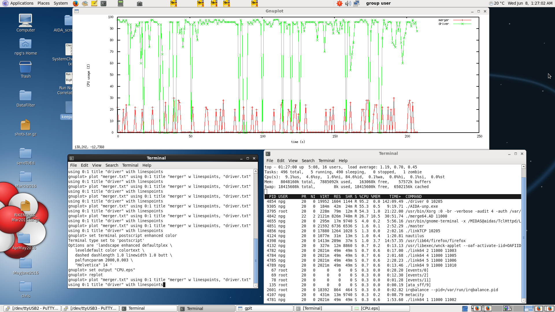
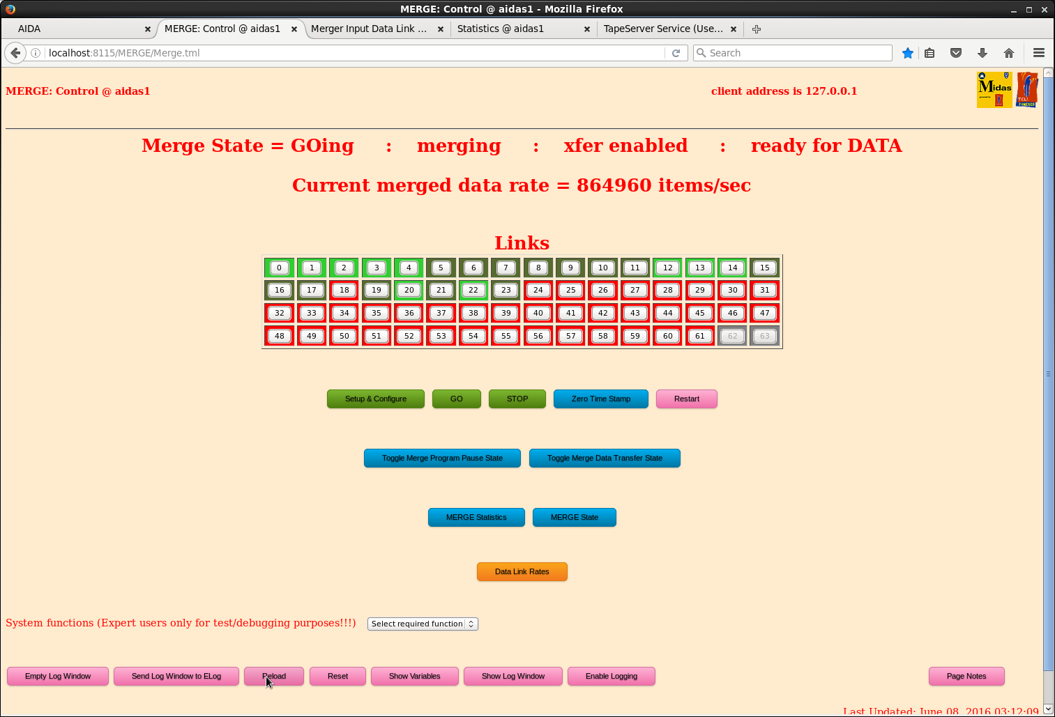
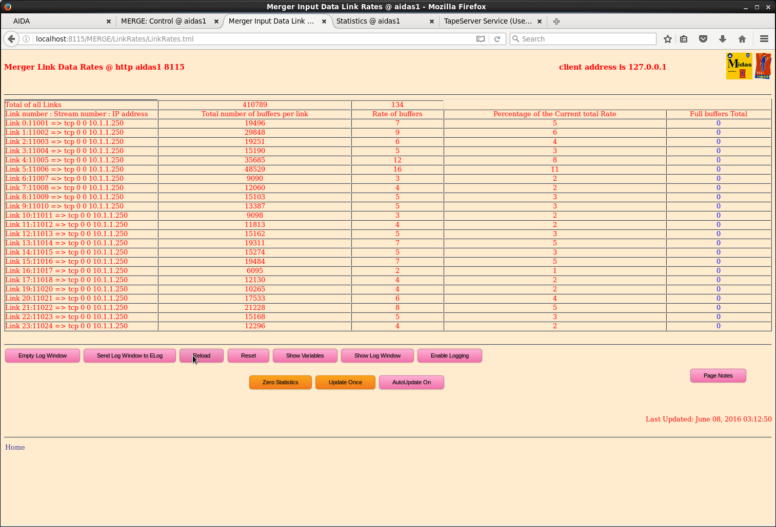
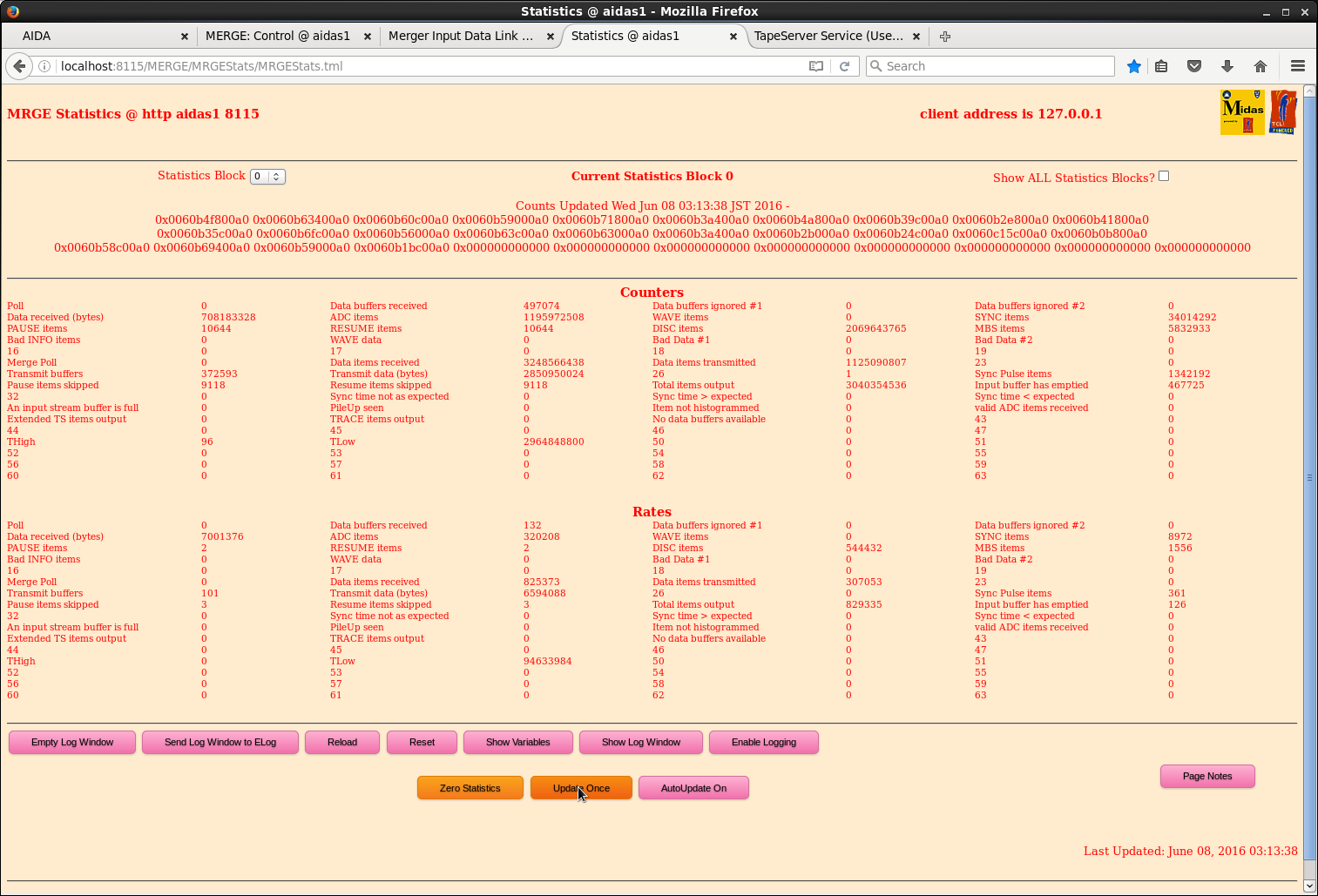
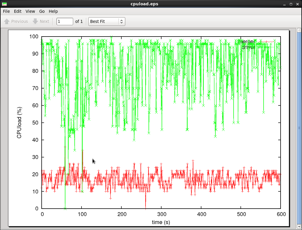
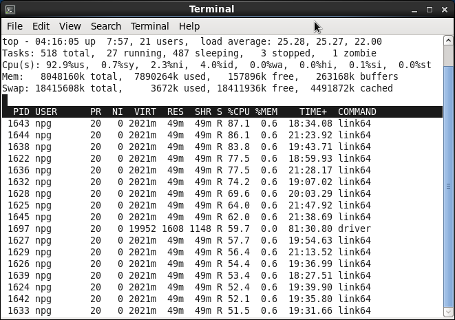
driver 0 10205 consuming almost 100% of CPU. Merger ~20% and data links ~1%
See attachments 1-4
02.15 Run R1220 n-rich setting (BigRIPS run 1218, EURICA off)
EURICA team retires for the night and cannot get it up and running
Biases and leak shown as attachments 5-6
Merger info is shown in attachments 7-9
CPU Load in attachment 10
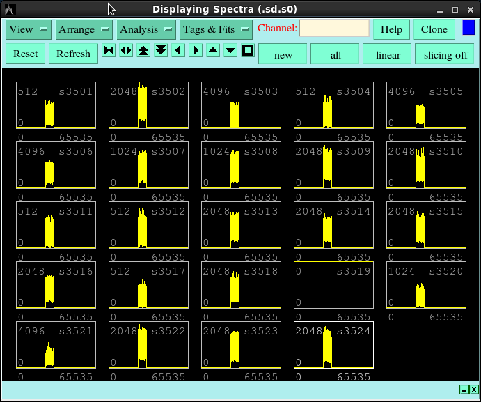
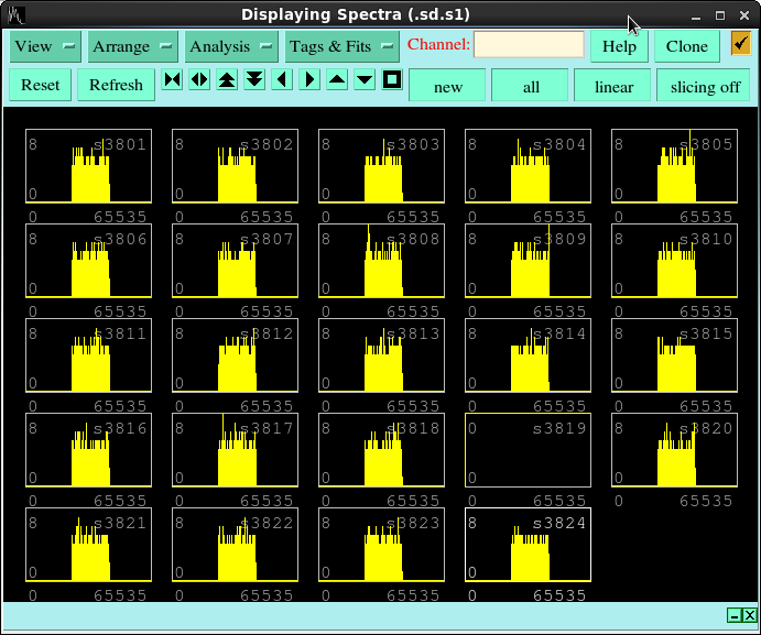
Timestamps against the ADCs and also SYNCS, respectively, attachments 11 and 12
3:31: Run stopped for the operator to tune the beam
F11 plastic rate was 700 cps (~heavy ion injection rate)
3:43 Run R1221 n-rich setting (BigRIPS 1219, no EURICA)
4 mm Al mask was removed.
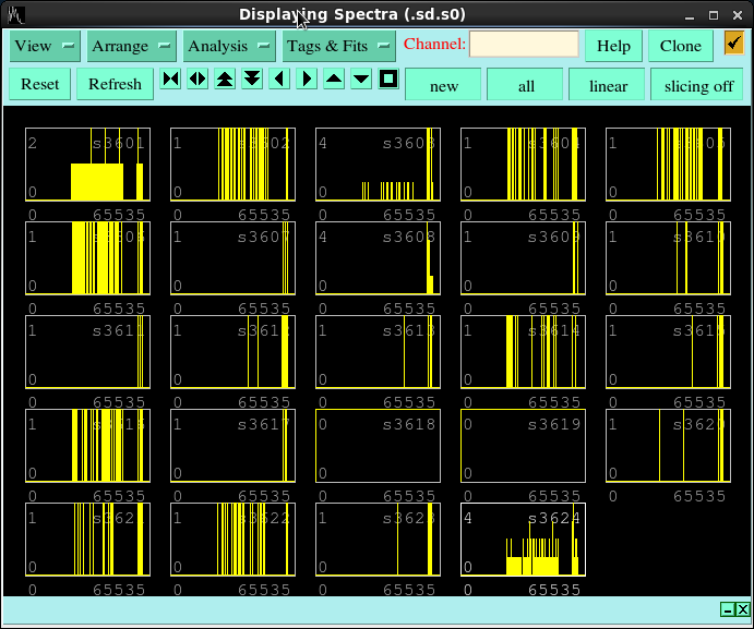
Pause calls vs. Timestamp is attachment 13
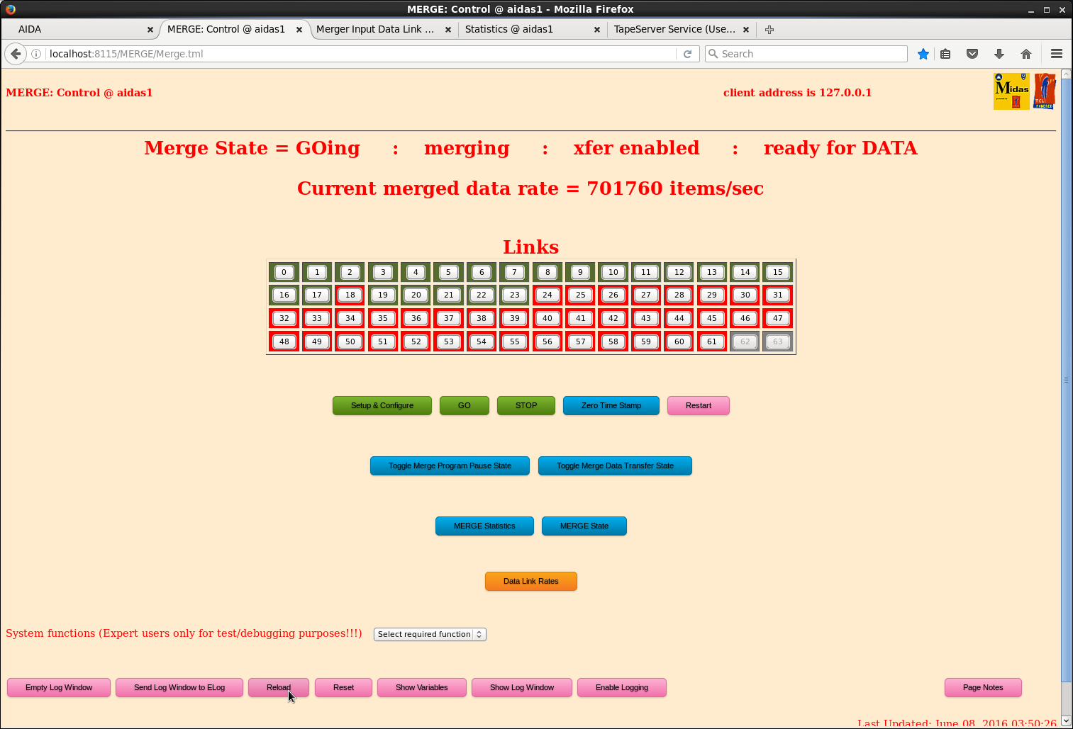
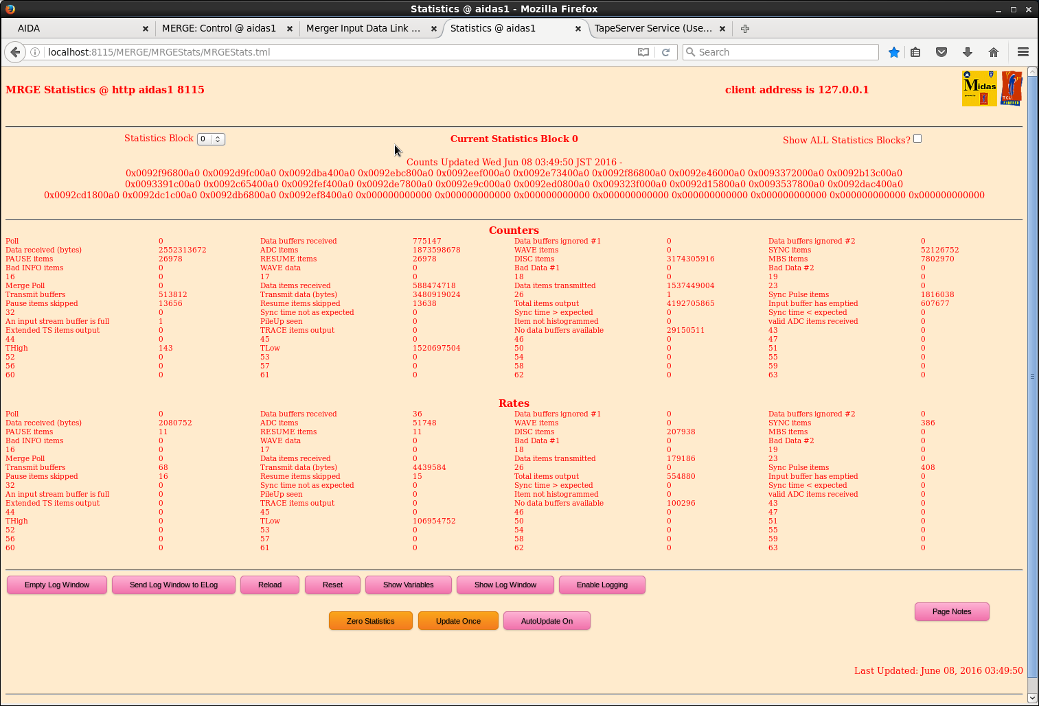
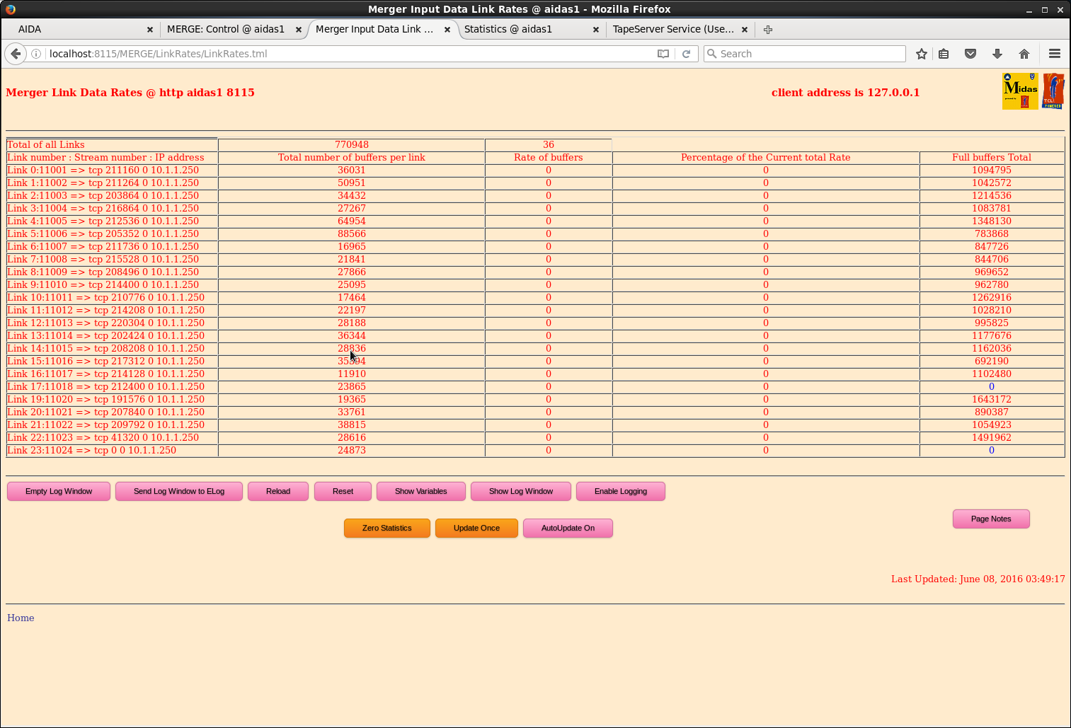
Merger screenshots are shown as attachments 14-16
F11 plastic rate is 850 or 900 cps after retune
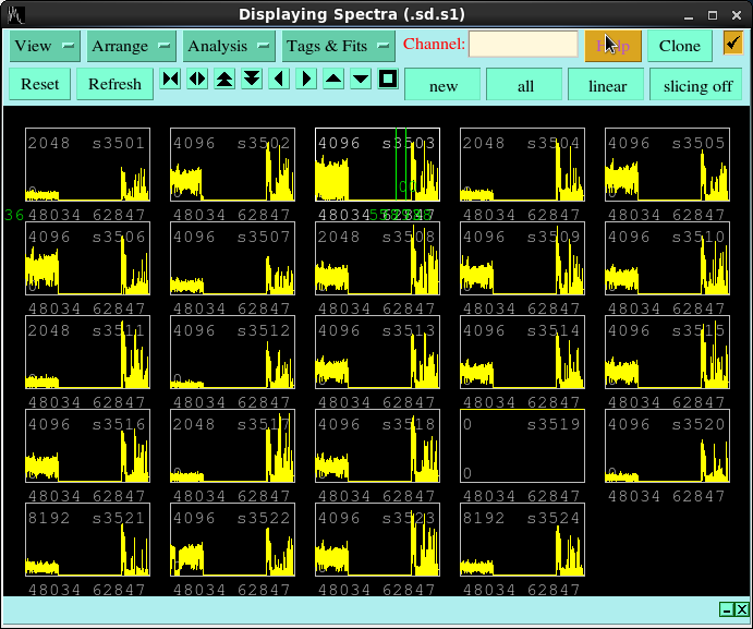
ADC v Timestamp is shown as attachment 17. It can be seen the rate was roughly constant before the operators stopped (corresponding to a long gap of no hits, but now we go up and down quite a lot in a rather ugly way
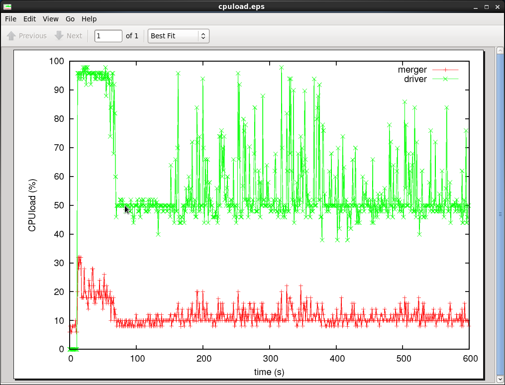
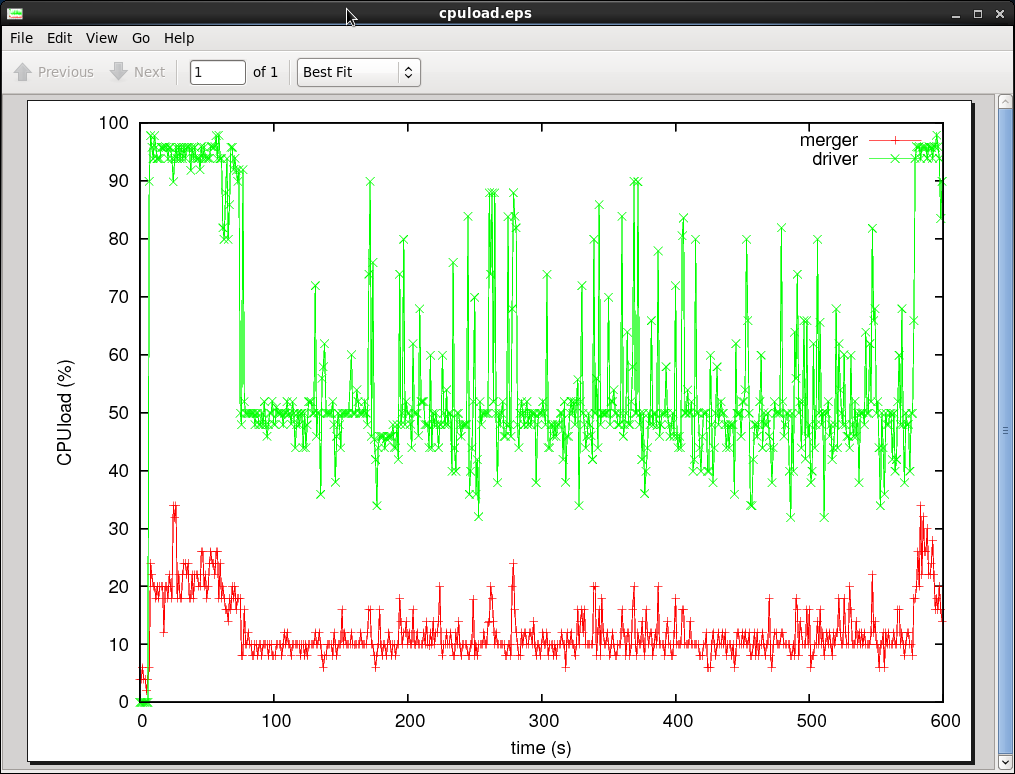
CPU stats (driver to write to HDD in green, merger in red) as attachment 18
At the time of ~90 in attachment 18, the linkers start to consume all available CPU resources, shown as attachment 19
04:35 Run R1222 n-rich setting (BigRIPS 1219 / 1220)
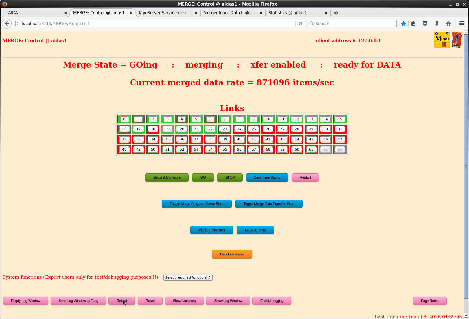
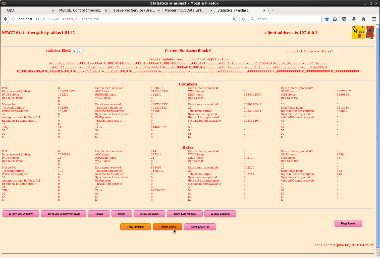
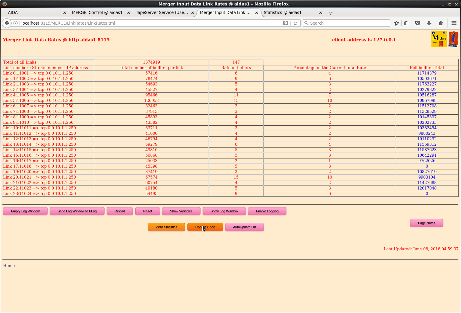
Ask the operators to reduce the beam intensity by "1/2" -> F11 plastic rate goes from 850 cps to 170 cps, so more like 1/4 effectively
Merger stats are shown as attachments 20, 21, 22.
nnaida1 and nnaida24 seemed to often show pauses (among other ones)
trying to understand what's going on with the display in Midas, because it has looped around to time zero and is putting new data on to the old data...?
It seems this condition is much better than before, though
05:33 stop the run
05:38 R R1223 n-rich setting (BigRIPS 1221)
Ask the operators to resume the previous beam intensity. (Now like 600 to 800 cps at the F11 plastic)
attachment 23 shows the beam coming on near time zero. within <100 seconds, the driver has to fight with many link64 instances and cannot operate correctly
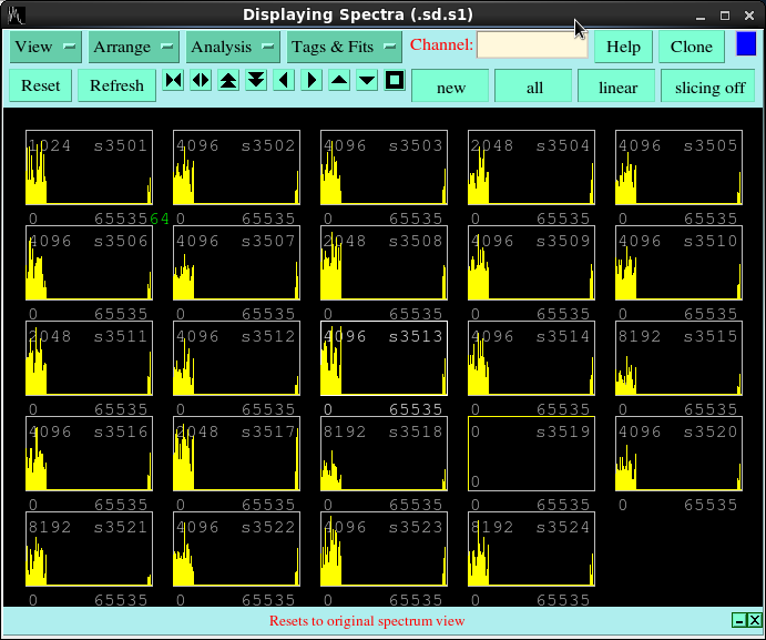
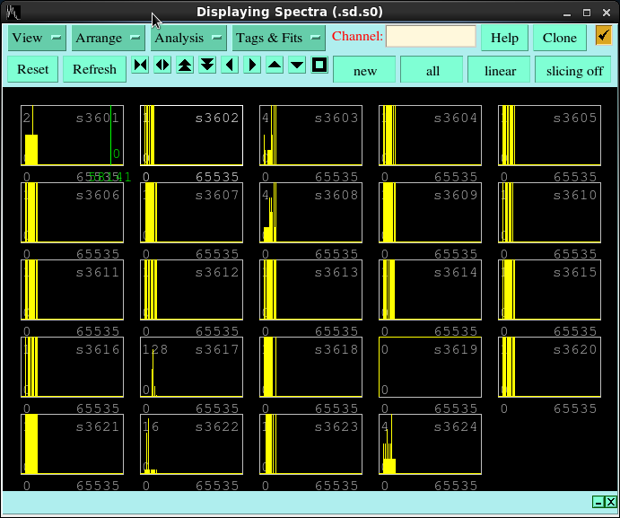
we understood how to clear the midas histograms so that we can make sense of things. attachment 24 is ADC, and attachment 25 is pause.
you can see some data come smoothly until the system locks down
06.11 R1223 stopped.
06.30 Started run R1224.
Moved Pb bricks downstream of F11 plastic inwards, from a separation of 15cm, to 4cm in an effort to reduce rate in AIDA.
F11 plastic rate ~900cps.
No change to vis scalar rates and data still being dropped.
06.45 Stopped run R1224.
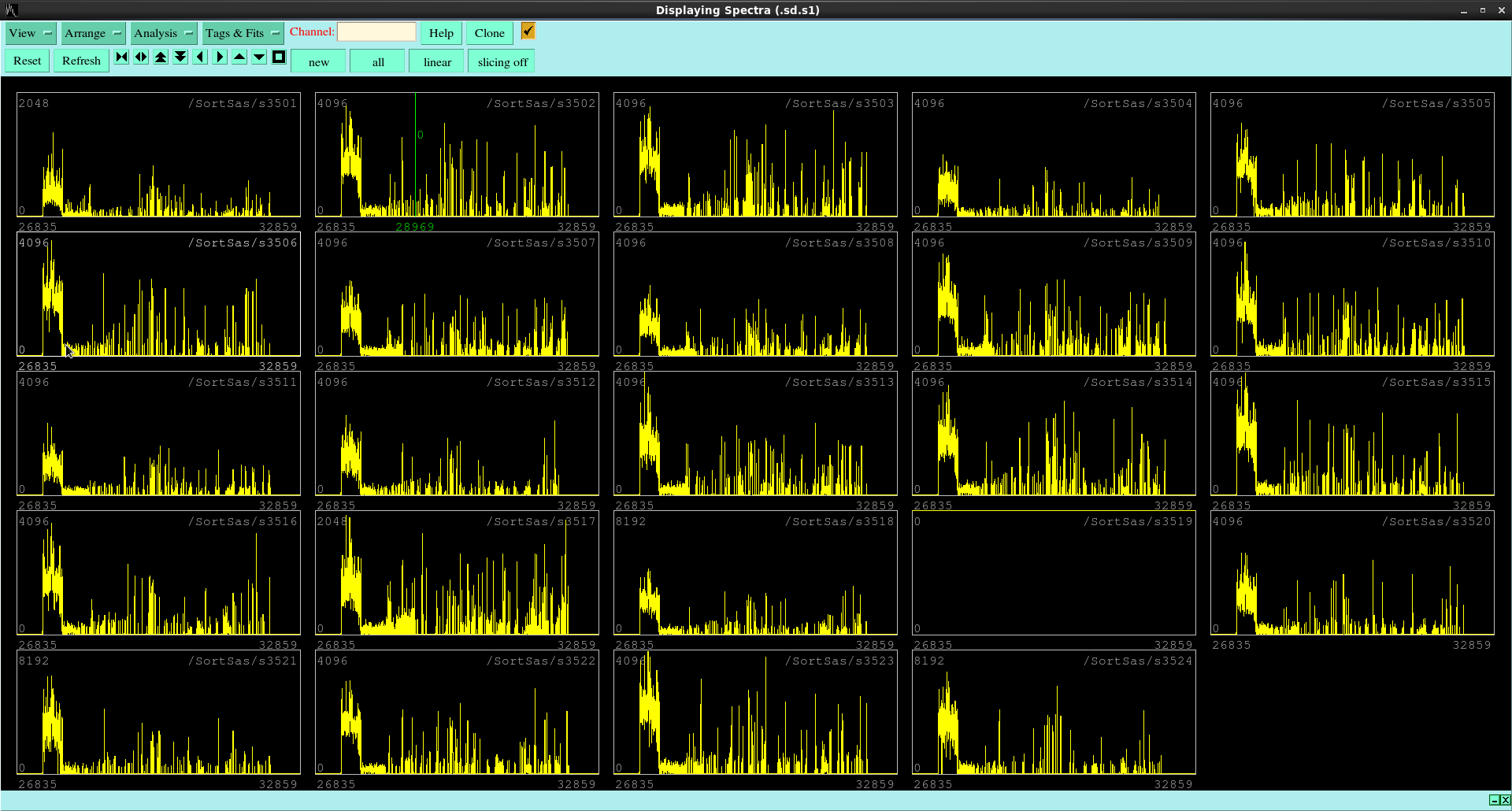
MIDAS plot of ADC vs Timestamp (attachment 26) shows characteristic behaviour.
Upon writing to disk, for the first minute or so link64 processes consume minimal CPU power. But then very quickly they ramp up consumption and ultimately choke the merger (it seems).
This is reflected in the ADC v TS plot. Continuous ADC data for first ~1min.
06.54 Moved Pb bricks to separation of 2cm. Started run R1225.
AIDA vis scalar rates reduced slightly, but no change to CPU usage and usual happens - data lost, link64 CPU usage spikes and chokes merger (seemingly).
F11 plastic rate ~900cps.
07.00 Run R1225 stopped.
SYNCs stopped being produced. Lost contact with nnaida1.
07.25 Pb bricks moved to 1cm apart. Run R1226 started.
No change to CPU usage (link64 still hogging everything). MIDAS online monitor lost in power cycle so cant view in real-time, but anticipate same outcome.
Sopped producing SYNCs 07.39. Run 1226 stopped.
08.20 Some trouble restarting DAQ and merger.
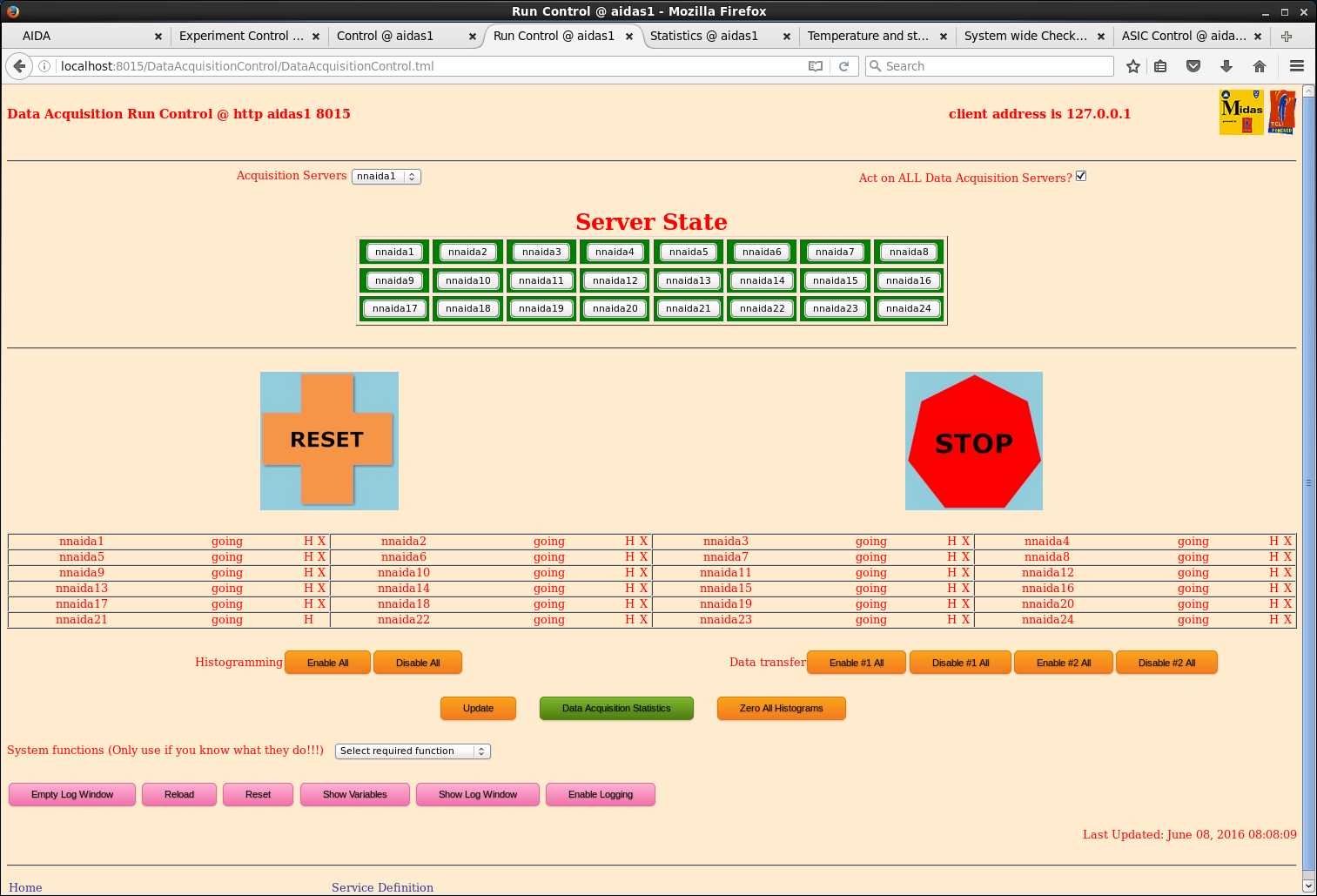
As nnaida19 has lost the 'H' for histogramming on the run control page, nnaida21 has now lost the 'X' for data transfer (see attachment 27).
Removed nnaida21 from merger and normal state of play resumed.
4mm holey plate + the one attached to it we installed dowstream of F11 plastic.
08.50 Run R1227 started.
CPU usage by link64 ~1% and driver ~70%, much more reasonable. When reloading merger web page, channels flash between bright green and olive. Good.
09.09 Changed to reference mass setting. Run R1227 stopped.
09.12 Run R1228 started on reference setting with holey plate still in place.
R1228 stopped 10.32 (for B2F/F11 entry)
|
| Attachment 1: merge_rate_resync.png
|
|
| Attachment 2: merge_resync.png
|
|
| Attachment 3: tape_resync.png
|
|
| Attachment 4: disk_driver_CPU_usage.png
|
|
| Attachment 5: bias1_R1220_0806-03.10.png
|
|
| Attachment 6: bias2_R1220_0806-03.10.png
|
|
| Attachment 7: R1220_MergeControl_0806-03.12.png
|
|
| Attachment 8: MergerLinkRates_R1220_0806-03.13.png
|
|
| Attachment 9: MergerStats_R1220_08-6-03.13.png
|
|
| Attachment 10: cpuload_R1220_0806-03.16.png
|
|
| Attachment 11: ADCvTimestamp_R1220_0806-03.17.png
|
|
| Attachment 12: SYNCSvTimestamp_R1220_0806-03.18.png
|
|
| Attachment 13: PauseVTimestamp_R1221_0806_03.51.png
|
|
| Attachment 14: MergeControl_R1221_0806_03.50.png
|
|
| Attachment 15: MergerStats_R1221_0806_03.50.png
|
|
| Attachment 16: MergerRates_R1221_0806_03.49.png
|
|
| Attachment 17: ADCvT_R1221_0806_04.02.png
|
|
| Attachment 18: CPULoad_R1221_0806_04.06.png
|
|
| Attachment 19: TOP_R1221_0806_04.16.png
|
|
| Attachment 20: Merger_R1222_0807-04.59.png
|
|
| Attachment 21: MergerStats_R1222_0806-05.00.png
|
|
| Attachment 22: MergerLink_R1222_0806-04.59.png
|
|
| Attachment 23: CPUStat_R1223_0806-05.58.png
|
|
| Attachment 24: ADC_v_T_R1223_0806-06.03.png
|
|
| Attachment 25: Pause_v_T_R1223_0806-06.04.png
|
|
| Attachment 26: ADCvTS_R1224_0639.png
|
|
| Attachment 27: nnaida21_noDataXfer.png
|
|