| ID |
Date |
Author |
Subject |
|
483
|
Wed Jan 31 09:49:38 2024 |
JM, TD | Optimising - Wednesday 31 |
Removed ground from DSSD #1 to the chamber and set MACBs so that timestamp is from the NIM WR emulator not the VME VETAR2.
Root MACB mode 0x3 -> 0xd - all other MACB modes 0x3 ( unchanged ).
No timestamps observed from the emulator. Re-set to take timestamps from the VETAR" unit -> all timestamps observed.
10:30
No pulser observed in nn FEE modules 9, 10, 13, 14.
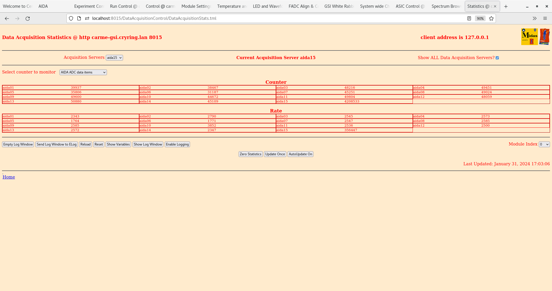
ADC data items check OK - all ~3k - attachment 2
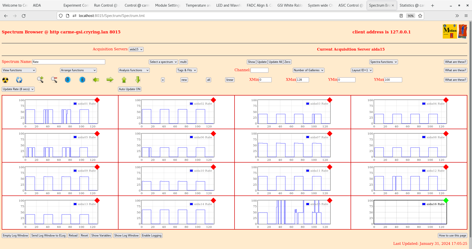
Rates - all OK - attachment 3
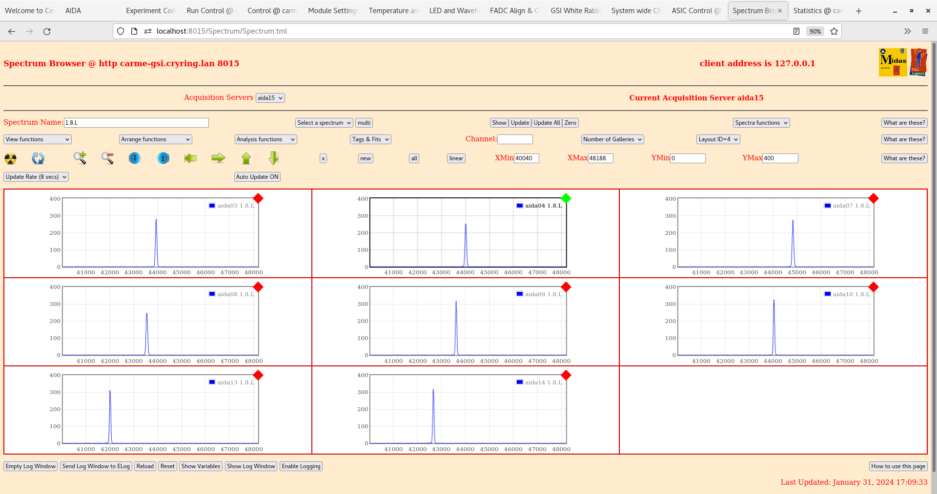
1.8L spectra. - attachment 4,5
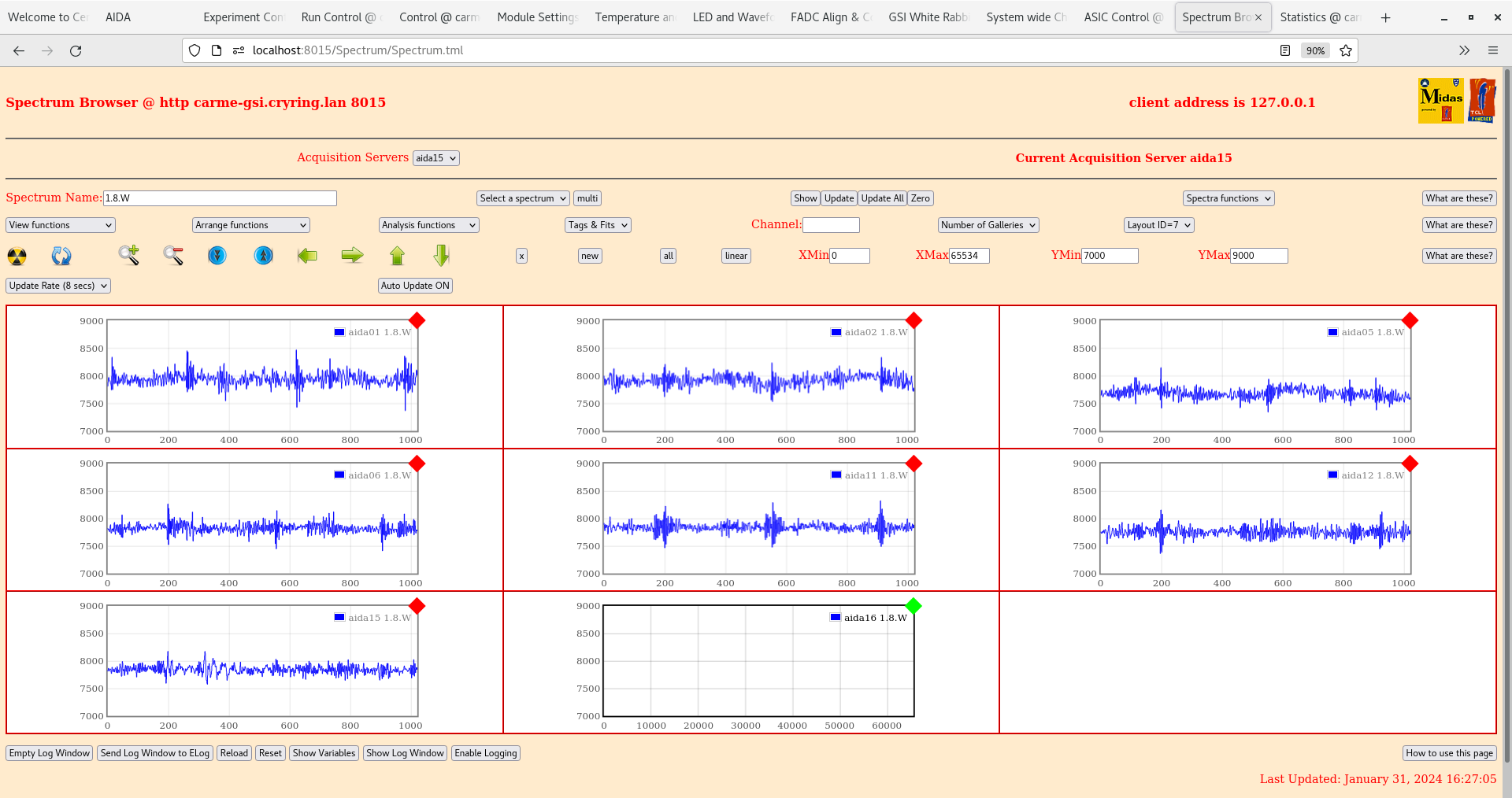
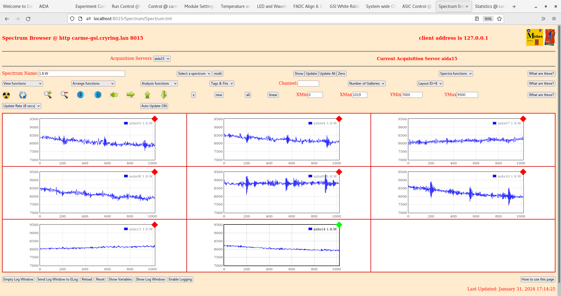
1.8W waveforms - attachment 6,7
11:00
Checked daisy chain which goes from 8->14->13->10->9. Replaced the lemo cable from 8->14 and pulsers re-appear. Rates all OK except aida10 which has now disappeared, tried asic check and reset and startup again no change in aida10.
Now majority of pulsers are observable the widths will be noted in a spreadsheet
After replacing lemo for nn pulser chain, all nn pulser widths decreased slightly ~10% for all nn FEEs, little change in pn pulser widths but n pulser for DSSD#1,2 appears more gaussian
11:44
FEE64s power cycled. aida10 now prioducing data.
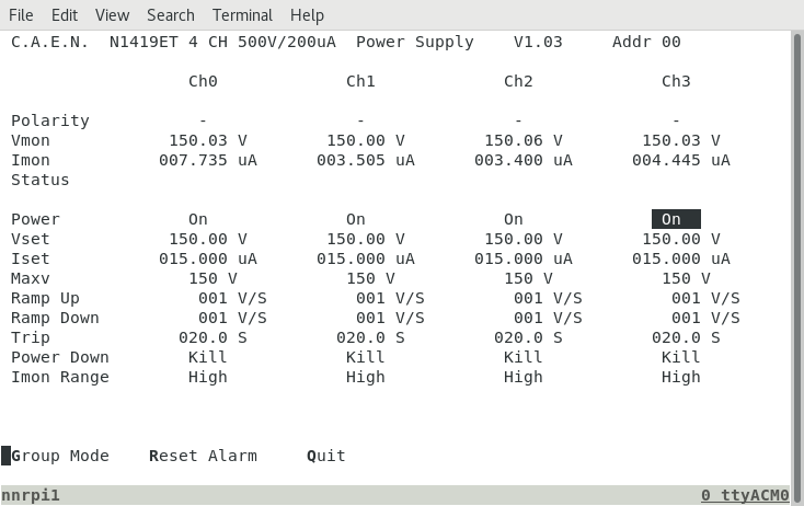
Removed internal jumper from CAEN N1419ET
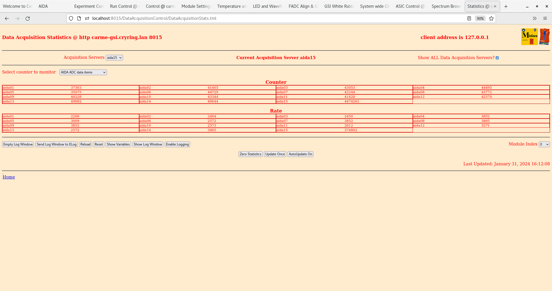
ADC data items check OK - all ~3k - attachment 8
Rates - all OK - attachment 9
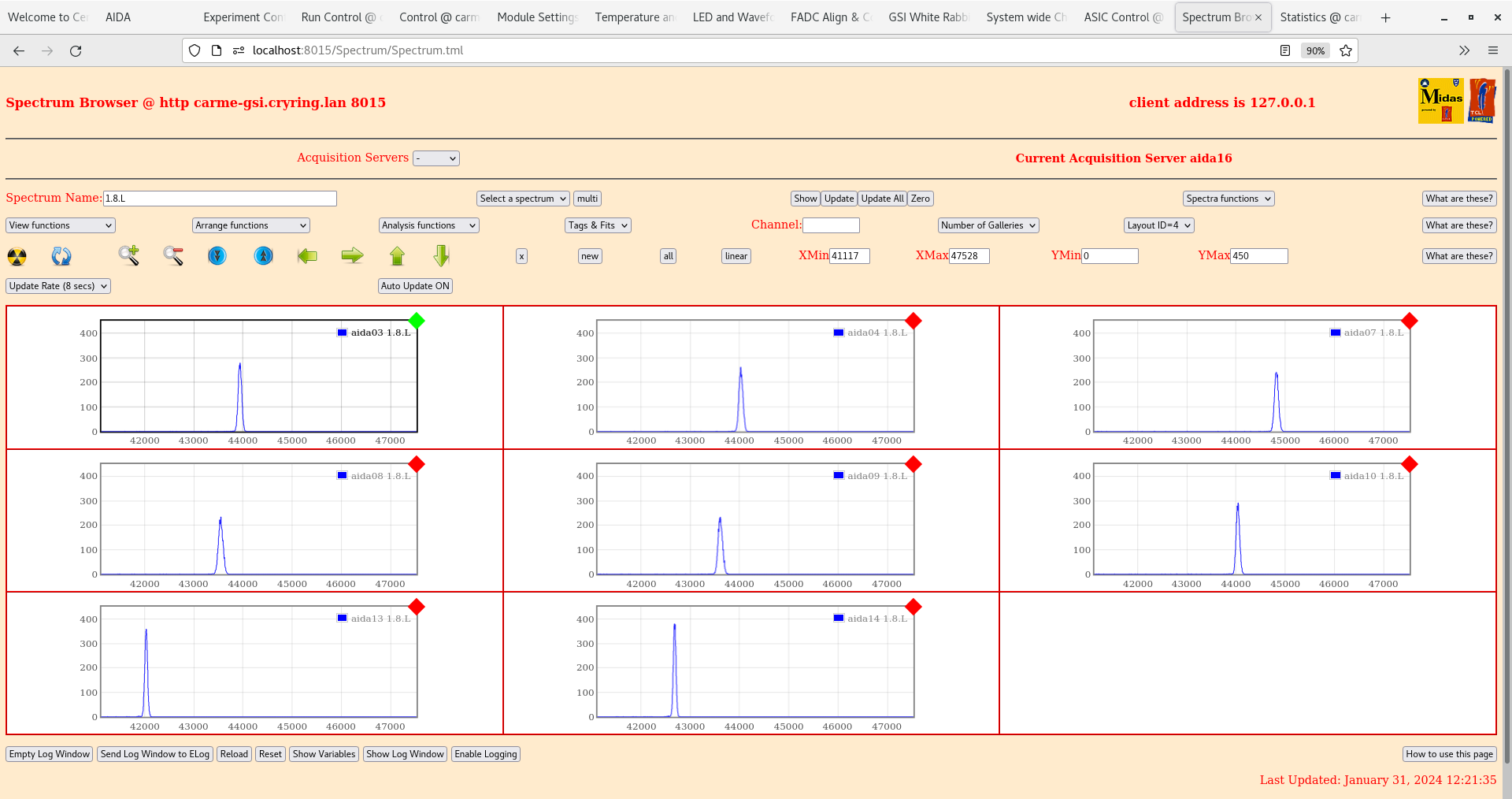
1.8L spectra - attachment 10,11 little change in pn pulser widths but nn pulser widths are slightly broader.
1.8W waveforms - attachment 12,13
15:50 Jumper re-mounted onto caen bias module
ADC data items check OK - all ~3k - attachment 14
Rates - all OK - attachment 15
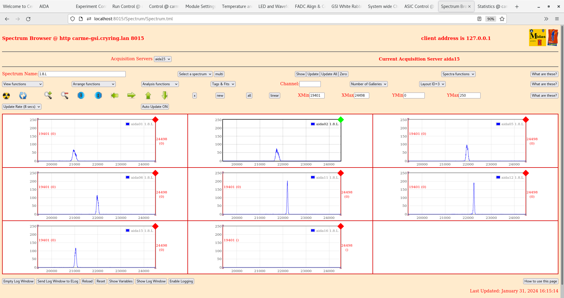
1.8L spectra - attachment 16,17
1.8W waveforms - attachment 18,19
16:45 Ground cables attached from water pipe (chamber ground) to lemo cable on aida08 (nn), aida13 (nn), aida09 (nn), aida01 (pn) so that all DSSDs are connected to chamber ground.
ADC data items check OK - all ~3k - attachment 20
Rates - all OK - attachment 21
1.8L spectra - attachment 22,23
1.8W waveforms - attachment 24,25
|
| Attachment 1: Screenshot_from_2024-01-31_10-30-51.png
|
|
| Attachment 2: Screenshot_from_2024-01-31_10-30-32.png
|

|
| Attachment 3: Screenshot_from_2024-01-31_10-35-29.png
|

|
| Attachment 4: Screenshot_from_2024-01-31_10-36-25.png
|

|
| Attachment 5: Screenshot_from_2024-01-31_10-40-38.png
|

|
| Attachment 6: Screenshot_from_2024-01-31_10-50-09.png
|

|
| Attachment 7: Screenshot_from_2024-01-31_10-51-15.png
|

|
| Attachment 8: Screenshot_from_2024-01-31_12-13-56.png
|

|
| Attachment 9: Screenshot_from_2024-01-31_12-15-41.png
|

|
| Attachment 10: Screenshot_from_2024-01-31_12-16-54.png
|

|
| Attachment 11: Screenshot_from_2024-01-31_12-21-42.png
|
|
| Attachment 12: Screenshot_from_2024-01-31_12-26-28.png
|

|
| Attachment 13: Screenshot_from_2024-01-31_12-27-33.png
|

|
| Attachment 14: Screenshot_from_2024-01-31_16-12-15.png
|
|
| Attachment 15: Screenshot_from_2024-01-31_16-14-25.png
|

|
| Attachment 16: Screenshot_from_2024-01-31_16-15-28.png
|
|
| Attachment 17: Screenshot_from_2024-01-31_16-22-14.png
|

|
| Attachment 18: Screenshot_from_2024-01-31_16-27-15.png
|
|
| Attachment 19: Screenshot_from_2024-01-31_16-28-06.png
|

|
| Attachment 20: Screenshot_from_2024-01-31_17-03-14.png
|
|
| Attachment 21: Screenshot_from_2024-01-31_17-05-33.png
|
|
| Attachment 22: Screenshot_from_2024-01-31_17-06-37.png
|

|
| Attachment 23: Screenshot_from_2024-01-31_17-09-40.png
|
|
| Attachment 24: Screenshot_from_2024-01-31_17-13-54.png
|

|
| Attachment 25: Screenshot_from_2024-01-31_17-14-32.png
|
|
|
482
|
Tue Jan 30 14:04:30 2024 |
NH | [HowTo] Update MACB Firmware |
This is how to update the MACB firmware using the opensource tool xc3sprog


Setup (only has to be done first time)
--------------------
Install xc3sprog and fxload (ubuntu: sudo apt install xc3sprog fxload)

To configure the USB programmer:
Download xilinx.tar.gz and put the hex files in /usr/share

Download the udev rules and put it in /etc/udev/rules.d

Run:
sudo udevadm control --reload-rules

[Taken from https://github.com/timvideos/litex-buildenv/wiki/Xilinx-Platform-Cable-USB-under-Linux]

Plug in programmer and should work

----------------------------------
Programming a MACB

Open MACB side panel and connect JTAG programmer to port

Plug MACB into NIM bin and power NIM bin on

Run
xc3sprog -c xpc -m -j

Expected output:
XC3SPROG (c) 2004-2011 xc3sprog project $Rev$ OS: Linux
Free software: If you contribute nothing, expect nothing!
Feedback on success/failure/enhancement requests:
        http://sourceforge.net/mail/?group_id=170565
Check Sourceforge for updates:
        http://sourceforge.net/projects/xc3sprog/develop

JTAG loc.:   0  IDCODE: 0x16d8c093  Desc:                  XC2C128_TQ144 Rev: A  IR length:  8

This confirms the JTAG is working

Then to program  run

xc3sprog -c xpc -m . macb_apr20.jed

The directory should contain the macb_apr20.jed and the xc2c128.map files

Expected output:
XC3SPROG (c) 2004-2011 xc3sprog project $Rev$ OS: Linux
Free software: If you contribute nothing, expect nothing!
Feedback on success/failure/enhancement requests:
        http://sourceforge.net/mail/?group_id=170565
Check Sourceforge for updates:
        http://sourceforge.net/projects/xc3sprog/develop

Programming row  81
Verify: Success

Now power off the NIM bin and remove the programmer and put the cover back on |
| Attachment 1: xusbdfwu.rules
|
# version 0003
ATTRS{idVendor}=="03fd", ATTRS{idProduct}=="0008", MODE="666"
SUBSYSTEMS=="usb", ACTION=="add", ATTRS{idVendor}=="03fd", ATTRS{idProduct}=="0007", RUN+="/sbin/fxload -v -t fx2 -I /usr/share/xusbdfwu.hex -D $tempnode"
SUBSYSTEMS=="usb", ACTION=="add", ATTRS{idVendor}=="03fd", ATTRS{idProduct}=="0009", RUN+="/sbin/fxload -v -t fx2 -I /usr/share/xusb_xup.hex -D $tempnode"
SUBSYSTEMS=="usb", ACTION=="add", ATTRS{idVendor}=="03fd", ATTRS{idProduct}=="000d", RUN+="/sbin/fxload -v -t fx2 -I /usr/share/xusb_emb.hex -D $tempnode"
SUBSYSTEMS=="usb", ACTION=="add", ATTRS{idVendor}=="03fd", ATTRS{idProduct}=="000f", RUN+="/sbin/fxload -v -t fx2 -I /usr/share/xusb_xlp.hex -D $tempnode"
SUBSYSTEMS=="usb", ACTION=="add", ATTRS{idVendor}=="03fd", ATTRS{idProduct}=="0013", RUN+="/sbin/fxload -v -t fx2 -I /usr/share/xusb_xp2.hex -D $tempnode"
SUBSYSTEMS=="usb", ACTION=="add", ATTRS{idVendor}=="03fd", ATTRS{idProduct}=="0015", RUN+="/sbin/fxload -v -t fx2 -I /usr/share/xusb_xse.hex -D $tempnode"
|
| Attachment 2: xilinx.tar.gz
|
| Attachment 3: xc2c128.map
|
																																																																																	user
6507	6523		6536	6552	6565	6581		6594	6610	6623	6639		6652	6668		6684			6700		6716			6732	6745	6761		6774	6790	6803	6819		6832	6848	6861	6877		6890	6906	20323	20339		20352	20368	20381	20397		20410	20426	20439	20455		20468	20484	20497	20513			20529		20545			20561	20574	20590	55324	20603	20619	20632	20648		20661	20677	20690	20706		20719	20735	sec_0
6508	6524		6537	6553	6566	6582		6595	6611	6624	6640		6653	6669		6685			6701		6717			6733	6746	6762		6775	6791	6804	6820		6833	6849	6862	6878		6891	6907	20324	20340		20353	20369	20382	20398		20411	20427	20440	20456		20469	20485	20498	20514			20530		20546			20562	20575	20591	55325	20604	20620	20633	20649		20662	20678	20691	20707		20720	20736	sec_1
6502	6509		6531	6538	6560	6567		6589	6596	6618	6625		6647	6654	6675			6691		6707			6723		6740	6747		6769	6776	6798	6805		6827	6834	6856	6863		6885	6892	20318	20325		20347	20354	20376	20383		20405	20412	20434	20441		20463	20470	20492	20499		20520		20536			20552		20569	20576		20598	20605	20627	20634		20656	20663	20685	20692		20714	20721	sec_2
6503	6510		6532	6539	6561	6568		6590	6597	6619	6626		6648	6655	6676			6692		6708			6724		6741	6748	55326	6770	6777	6799	6806		6828	6835	6857	6864		6886	6893	20319	20326		20348	20355	20377	20384		20406	20413	20435	20442		20464	20471	20493	20500		20521		20537			20553		20570	20577	55330	20599	20606	20628	20635		20657	20664	20686	20693		20715	20722	sec_3
6501	6511		6530	6540	6559	6569		6588	6598	6617	6627		6646	6656											6739	6749	55327	6768	6778	6797	6807		6826	6836	6855	6865		6884	6894	20317	20327		20346	20356	20375	20385		20404	20414	20433	20443		20462	20472	20491	20501									20568	20578	55331	20597	20607	20626	20636		20655	20665	20684	20694		20713	20723	sec_4
6504	6512		6533	6541	6562	6570		6591	6599	6620	6628		6649	6657											6742	6750	55328	6771	6779	6800	6808		6829	6837	6858	6866		6887	6895	20320	20328		20349	20357	20378	20386		20407	20415	20436	20444		20465	20473	20494	20502									20571	20579	55332	20600	20608	20629	20637		20658	20666	20687	20695		20716	20724	sec_5
6505	6521		6534	6550	6563	6579		6592	6608	6621	6637		6650	6666											6743	6759	55329	6772	6788	6801	6817		6830	6846	6859	6875		6888	6904	20321	20337		20350	20366	20379	20395		20408	20424	20437	20453		20466	20482	20495	20511									20572	20588	55333	20601	20617	20630	20646		20659	20675	20688	20704		20717	20733	sec_6
6522			6551		6580			6609		6638			6667												6760			6789		6818			6847		6876			6905		20338			20367		20396			20425		20454			20483		20512										20589		55336	20618		20647			20676		20705			20734		done_0
6496	6516		6525	6545	6554	6574		6583	6603	6612	6632		6641	6661	6670			6686		6702			6718		6734	6754		6763	6783	6792	6812		6821	6841	6850	6870		6879	6899	20312	20332		20341	20361	20370	20390		20399	20419	20428	20448		20457	20477	20486	20506		20515		20531			20547		20563	20583	55338	20592	20612	20621	20641		20650	20670	20679	20699		20708	20728	done_1
6497	6517		6526	6546	6555	6575		6584	6604	6613	6633		6642	6662	6671	6680		6687	6696	6703	6712		6719	6728	6735	6755		6764	6784	6793	6813		6822	6842	6851	6871		6880	6900	20313	20333		20342	20362	20371	20391		20400	20420	20429	20449		20458	20478	20487	20507		20516	20525	20532	20541		20548	20557	20564	20584	55340	20593	20613	20622	20642		20651	20671	20680	20700		20709	20729
6498	6518		6527	6547	6556	6576		6585	6605	6614	6634		6643	6663	6672	6681		6688	6697	6704	6713		6720	6729	6736	6756		6765	6785	6794	6814		6823	6843	6852	6872		6881	6901	20314	20334		20343	20363	20372	20392		20401	20421	20430	20450		20459	20479	20488	20508		20517	20526	20533	20542		20549	20558	20565	20585		20594	20614	20623	20643		20652	20672	20681	20701		20710	20730
6499	6519		6528	6548	6557	6577		6586	6606	6615	6635		6644	6664	6673	6682		6689	6698	6705	6714		6721	6730	6737	6757		6766	6786	6795	6815		6824	6844	6853	6873		6882	6902	20315	20335		20344	20364	20373	20393		20402	20422	20431	20451		20460	20480	20489	20509		20518	20527	20534	20543		20550	20559	20566	20586		20595	20615	20624	20644		20653	20673	20682	20702		20711	20731
6500	6520		6529	6549	6558	6578		6587	6607	6616	6636		6645	6665	6674	6683		6690	6699	6706	6715		6722	6731	6738	6758		6767	6787	6796	6816		6825	6845	6854	6874		6883	6903	20316	20336		20345	20365	20374	20394		20403	20423	20432	20452		20461	20481	20490	20510		20519	20528	20535	20544		20551	20560	20567	20587		20596	20616	20625	20645		20654	20674	20683	20703		20712	20732
6506	6513		6535	6542	6564	6571		6593	6600	6622	6629		6651	6658		6677			6693		6709			6725	6744	6751		6773	6780	6802	6809		6831	6838	6860	6867		6889	6896	20322	20329		20351	20358	20380	20387		20409	20416	20438	20445		20467	20474	20496	20503			20522		20538			20554	20573	20580		20602	20609	20631	20638		20660	20667	20689	20696		20718	20725
6515	6514		6544	6543	6573	6572		6602	6601	6631	6630		6660	6659	6679	6678		6695	6694	6711	6710		6727	6726	6753	6752		6782	6781	6811	6810		6840	6839	6869	6868		6898	6897	20331	20330		20360	20359	20389	20388		20418	20417	20447	20446		20476	20475	20505	20504		20524	20523	20540	20539		20556	20555	20582	20581		20611	20610	20640	20639		20669	20668	20698	20697		20727	20726
5728	5760		5792	5824	5856		5888	5920			5952	5984	6016		6048	6080	5600		5632	5696		5664	6128	6160		6192	6224	6256			6288	6320		6352	6384	6416		6448	6480	19544	19576		19608	19640	19672		19704	19736			19768	19800	19832		19864	19896	19416		19448	19512		19480	19944	19976		20008	20040	20072			20104	20136		20168	20200	20232		20264	20296
5744	5776		5808	5840	5872		5904	5936			5968	6000	6032		6064	6096	5616		5648	5712		5680	6112	6144		6176	6208	6240			6272	6304		6336	6368	6400		6432	6464	19560	19592		19624	19656	19688		19720	19752			19784	19816	19848		19880	19912	19432		19464	19528		19496	19928	19960		19992	20024	20056			20088	20120		20152	20184	20216		20248	20280
5729	5761		5793	5825	5857		5889	5921			5953	5985	6017		6049	6081	5601		5633	5697		5665	6129	6161		6193	6225	6257			6289	6321		6353	6385	6417		6449	6481	19545	19577		19609	19641	19673		19705	19737			19769	19801	19833		19865	19897	19417		19449	19513		19481	19945	19977		20009	20041	20073			20105	20137		20169	20201	20233		20265	20297
5745	5777		5809	5841	5873		5905	5937			5969	6001	6033		6065	6097	5617		5649	5713		5681	6113	6145		6177	6209	6241			6273	6305		6337	6369	6401		6433	6465	19561	19593		19625	19657	19689		19721	19753			19785	19817	19849		19881	19913	19433		19465	19529		19497	19929	19961		19993	20025	20057			20089	20121		20153	20185	20217		20249	20281
5730	5762		5794	5826	5858		5890	5922			5954	5986	6018		6050	6082	5602		5634	5698		5666	6130	6162		6194	6226	6258			6290	6322		6354	6386	6418		6450	6482	19546	19578		19610	19642	19674		19706	19738			19770	19802	19834		19866	19898	19418		19450	19514		19482	19946	19978		20010	20042	20074			20106	20138		20170	20202	20234		20266	20298
5746	5778		5810	5842	5874		5906	5938			5970	6002	6034		6066	6098	5618		5650	5714		5682	6114	6146		6178	6210	6242			6274	6306		6338	6370	6402		6434	6466	19562	19594		19626	19658	19690		19722	19754			19786	19818	19850		19882	19914	19434		19466	19530		19498	19930	19962		19994	20026	20058			20090	20122		20154	20186	20218		20250	20282
5731	5763		5795	5827	5859		5891	5923			5955	5987	6019		6051	6083	5603		5635	5699		5667	6131	6163		6195	6227	6259			6291	6323		6355	6387	6419		6451	6483	19547	19579		19611	19643	19675		19707	19739			19771	19803	19835		19867	19899	19419		19451	19515		19483	19947	19979		20011	20043	20075			20107	20139		20171	20203	20235		20267	20299
5747	5779		5811	5843	5875		5907	5939			5971	6003	6035		6067	6099	5619		5651	5715		5683	6115	6147		6179	6211	6243			6275	6307		6339	6371	6403		6435	6467	19563	19595		19627	19659	19691		19723	19755			19787	19819	19851		19883	19915	19435		19467	19531		19499	19931	19963		19995	20027	20059			20091	20123		20155	20187	20219		20251	20283
5732	5764		5796	5828	5860		5892	5924			5956	5988	6020		6052	6084	5604		5636	5700		5668	6132	6164		6196	6228	6260			6292	6324		6356	6388	6420		6452	6484	19548	19580		19612	19644	19676		19708	19740			19772	19804	19836		19868	19900	19420		19452	19516		19484	19948	19980		20012	20044	20076			20108	20140		20172	20204	20236		20268	20300
5748	5780		5812	5844	5876		5908	5940			5972	6004	6036		6068	6100	5620		5652	5716		5684	6116	6148		6180	6212	6244			6276	6308		6340	6372	6404		6436	6468	19564	19596		19628	19660	19692		19724	19756			19788	19820	19852		19884	19916	19436		19468	19532		19500	19932	19964		19996	20028	20060			20092	20124		20156	20188	20220		20252	20284
5733	5765		5797	5829	5861		5893	5925			5957	5989	6021		6053	6085	5605		5637	5701		5669	6133	6165		6197	6229	6261			6293	6325		6357	6389	6421		6453	6485	19549	19581		19613	19645	19677		19709	19741			19773	19805	19837		19869	19901	19421		19453	19517		19485	19949	19981		20013	20045	20077			20109	20141		20173	20205	20237		20269	20301
5749	5781		5813	5845	5877		5909	5941			5973	6005	6037		6069	6101	5621		5653	5717		5685	6117	6149		6181	6213	6245			6277	6309		6341	6373	6405		6437	6469	19565	19597		19629	19661	19693		19725	19757			19789	19821	19853		19885	19917	19437		19469	19533		19501	19933	19965		19997	20029	20061			20093	20125		20157	20189	20221		20253	20285
5734	5766		5798	5830	5862		5894	5926			5958	5990	6022		6054	6086	5606		5638	5702		5670	6134	6166		6198	6230	6262			6294	6326		6358	6390	6422		6454	6486	19550	19582		19614	19646	19678		19710	19742			19774	19806	19838		19870	19902	19422		19454	19518		19486	19950	19982		20014	20046	20078			20110	20142		20174	20206	20238		20270	20302
5750	5782		5814	5846	5878		5910	5942			5974	6006	6038		6070	6102	5622		5654	5718		5686	6118	6150		6182	6214	6246			6278	6310		6342	6374	6406		6438	6470	19566	19598		19630	19662	19694		19726	19758			19790	19822	19854		19886	19918	19438		19470	19534		19502	19934	19966		19998	20030	20062			20094	20126		20158	20190	20222		20254	20286
5735	5767		5799	5831	5863		5895	5927			5959	5991	6023		6055	6087	5607		5639	5703		5671	6135	6167		6199	6231	6263			6295	6327		6359	6391	6423		6455	6487	19551	19583		19615	19647	19679		19711	19743			19775	19807	19839		19871	19903	19423		19455	19519		19487	19951	19983		20015	20047	20079			20111	20143		20175	20207	20239		20271	20303
5751	5783		5815	5847	5879		5911	5943			5975	6007	6039		6071	6103	5623		5655	5719		5687	6119	6151		6183	6215	6247			6279	6311		6343	6375	6407		6439	6471	19567	19599		19631	19663	19695		19727	19759			19791	19823	19855		19887	19919	19439		19471	19535		19503	19935	19967		19999	20031	20063			20095	20127		20159	20191	20223		20255	20287
5736	5768		5800	5832	5864		5896	5928			5960	5992	6024		6056	6088	5608		5640	5704		5672	6136	6168		6200	6232	6264			6296	6328		6360	6392	6424		6456	6488	19552	19584		19616	19648	19680		19712	19744			19776	19808	19840		19872	19904	19424		19456	19520		19488	19952	19984		20016	20048	20080			20112	20144		20176	20208	20240		20272	20304
5752	5784		5816	5848	5880		5912	5944			5976	6008	6040		6072	6104	5624		5656	5720		5688	6120	6152		6184	6216	6248			6280	6312		6344	6376	6408		6440	6472	19568	19600		19632	19664	19696		19728	19760			19792	19824	19856		19888	19920	19440		19472	19536		19504	19936	19968		20000	20032	20064			20096	20128		20160	20192	20224		20256	20288
5737	5769		5801	5833	5865		5897	5929			5961	5993	6025		6057	6089	5609		5641	5705		5673	6137	6169		6201	6233	6265			6297	6329		6361	6393	6425		6457	6489	19553	19585		19617	19649	19681		19713	19745			19777	19809	19841		19873	19905	19425		19457	19521		19489	19953	19985		20017	20049	20081			20113	20145		20177	20209	20241		20273	20305
5753	5785		5817	5849	5881		5913	5945			5977	6009	6041		6073	6105	5625		5657	5721		5689	6121	6153		6185	6217	6249			6281	6313		6345	6377	6409		6441	6473	19569	19601		19633	19665	19697		19729	19761			19793	19825	19857		19889	19921	19441		19473	19537		19505	19937	19969		20001	20033	20065			20097	20129		20161	20193	20225		20257	20289
5738	5770		5802	5834	5866		5898	5930			5962	5994	6026		6058	6090	5610		5642	5706		5674	6138	6170		6202	6234	6266			6298	6330		6362	6394	6426		6458	6490	19554	19586		19618	19650	19682		19714	19746			19778	19810	19842		19874	19906	19426		19458	19522		19490	19954	19986		20018	20050	20082			20114	20146		20178	20210	20242		20274	20306
5754	5786		5818	5850	5882		5914	5946			5978	6010	6042		6074	6106	5626		5658	5722		5690	6122	6154		6186	6218	6250			6282	6314		6346	6378	6410		6442	6474	19570	19602		19634	19666	19698		19730	19762			19794	19826	19858		19890	19922	19442		19474	19538		19506	19938	19970		20002	20034	20066			20098	20130		20162	20194	20226		20258	20290
5739	5771		5803	5835	5867		5899	5931			5963	5995	6027		6059	6091	5611		5643	5707		5675	6139	6171		6203	6235	6267			6299	6331		6363	6395	6427		6459	6491	19555	19587		19619	19651	19683		19715	19747			19779	19811	19843		19875	19907	19427		19459	19523		19491	19955	19987		20019	20051	20083			20115	20147		20179	20211	20243		20275	20307
5755	5787		5819	5851	5883		5915	5947			5979	6011	6043		6075	6107	5627		5659	5723		5691	6123	6155		6187	6219	6251			6283	6315		6347	6379	6411		6443	6475	19571	19603		19635	19667	19699		19731	19763			19795	19827	19859		19891	19923	19443		19475	19539		19507	19939	19971		20003	20035	20067			20099	20131		20163	20195	20227		20259	20291
5740	5772		5804	5836	5868		5900	5932			5964	5996	6028		6060	6092	5612		5644	5708		5676	6140	6172		6204	6236	6268			6300	6332		6364	6396	6428		6460	6492	19556	19588		19620	19652	19684		19716	19748			19780	19812	19844		19876	19908	19428		19460	19524		19492	19956	19988		20020	20052	20084			20116	20148		20180	20212	20244		20276	20308
5756	5788		5820	5852	5884		5916	5948			5980	6012	6044		6076	6108	5628		5660	5724		5692	6124	6156		6188	6220	6252			6284	6316		6348	6380	6412		6444	6476	19572	19604		19636	19668	19700		19732	19764			19796	19828	19860		19892	19924	19444		19476	19540		19508	19940	19972		20004	20036	20068			20100	20132		20164	20196	20228		20260	20292
5741	5773		5805	5837	5869		5901	5933			5965	5997	6029		6061	6093	5613		5645	5709		5677	6141	6173		6205	6237	6269			6301	6333		6365	6397	6429		6461	6493	19557	19589		19621	19653	19685		19717	19749			19781	19813	19845		19877	19909	19429		19461	19525		19493	19957	19989		20021	20053	20085			20117	20149		20181	20213	20245		20277	20309
5757	5789		5821	5853	5885		5917	5949			5981	6013	6045		6077	6109	5629		5661	5725		5693	6125	6157		6189	6221	6253			6285	6317		6349	6381	6413		6445	6477	19573	19605		19637	19669	19701		19733	19765			19797	19829	19861		19893	19925	19445		19477	19541		19509	19941	19973		20005	20037	20069			20101	20133		20165	20197	20229		20261	20293
5742	5774		5806	5838	5870		5902	5934			5966	5998	6030		6062	6094	5614		5646	5710		5678	6142	6174		6206	6238	6270			6302	6334		6366	6398	6430		6462	6494	19558	19590		19622	19654	19686		19718	19750			19782	19814	19846		19878	19910	19430		19462	19526		19494	19958	19990		20022	20054	20086			20118	20150		20182	20214	20246		20278	20310
5758	5790		5822	5854	5886		5918	5950			5982	6014	6046		6078	6110	5630		5662	5726		5694	6126	6158		6190	6222	6254			6286	6318		6350	6382	6414		6446	6478	19574	19606		19638	19670	19702		19734	19766			19798	19830	19862		19894	19926	19446		19478	19542		19510	19942	19974		20006	20038	20070			20102	20134		20166	20198	20230		20262	20294
5743	5775		5807	5839	5871		5903	5935			5967	5999	6031		6063	6095	5615		5647	5711		5679	6143	6175		6207	6239	6271			6303	6335		6367	6399	6431		6463	6495	19559	19591		19623	19655	19687		19719	19751			19783	19815	19847		19879	19911	19431		19463	19527		19495	19959	19991		20023	20055	20087			20119	20151		20183	20215	20247		20279	20311
5759	5791		5823	5855	5887		5919	5951			5983	6015	6047		6079	6111	5631		5663	5727		5695	6127	6159		6191	6223	6255			6287	6319		6351	6383	6415		6447	6479	19575	19607		19639	19671	19703		19735	19767			19799	19831	19863		19895	19927	19447		19479	19543		19511	19943	19975		20007	20039	20071			20103	20135		20167	20199	20231		20263	20295
1121	1123	1125	1127	1129	1131	1133	1135	1137	1139	1141	1143	1145	1147	1149	1151	1153	1155	1157	1159	1161	1163	1165	1167	1169	1171	1173	1175	1177	1179	1181	1183	1185	1187	1189	1191	1193	1195	1197	1199	14937	14939	14941	14943	14945	14947	14949	14951	14953	14955	14957	14959	14961	14963	14965	14967	14969	14971	14973	14975	14977	14979	14981	14983	14985	14987	14989	14991	14993	14995	14997	14999	15001	15003	15005	15007	15009	15011	15013	15015
1120	1122	1124	1126	1128	1130	1132	1134	1136	1138	1140	1142	1144	1146	1148	1150	1152	1154	1156	1158	1160	1162	1164	1166	1168	1170	1172	1174	1176	1178	1180	1182	1184	1186	1188	1190	1192	1194	1196	1198	14936	14938	14940	14942	14944	14946	14948	14950	14952	14954	14956	14958	14960	14962	14964	14966	14968	14970	14972	14974	14976	14978	14980	14982	14984	14986	14988	14990	14992	14994	14996	14998	15000	15002	15004	15006	15008	15010	15012	15014
1201	1203	1205	1207	1209	1211	1213	1215	1217	1219	1221	1223	1225	1227	1229	1231	1233	1235	1237	1239	1241	1243	1245	1247	1249	1251	1253	1255	1257	1259	1261	1263	1265	1267	1269	1271	1273	1275	1277	1279	15017	15019	15021	15023	15025	15027	15029	15031	15033	15035	15037	15039	15041	15043	15045	15047	15049	15051	15053	15055	15057	15059	15061	15063	15065	15067	15069	15071	15073	15075	15077	15079	15081	15083	15085	15087	15089	15091	15093	15095
1200	1202	1204	1206	1208	1210	1212	1214	1216	1218	1220	1222	1224	1226	1228	1230	1232	1234	1236	1238	1240	1242	1244	1246	1248	1250	1252	1254	1256	1258	1260	1262	1264	1266	1268	1270	1272	1274	1276	1278	15016	15018	15020	15022	15024	15026	15028	15030	15032	15034	15036	15038	15040	15042	15044	15046	15048	15050	15052	15054	15056	15058	15060	15062	15064	15066	15068	15070	15072	15074	15076	15078	15080	15082	15084	15086	15088	15090	15092	15094
1281	1283	1285	1287	1289	1291	1293	1295	1297	1299	1301	1303	1305	1307	1309	1311	1313	1315	1317	1319	1321	1323	1325	1327	1329	1331	1333	1335	1337	1339	1341	1343	1345	1347	1349	1351	1353	1355	1357	1359	15097	15099	15101	15103	15105	15107	15109	15111	15113	15115	15117	15119	15121	15123	15125	15127	15129	15131	15133	15135	15137	15139	15141	15143	15145	15147	15149	15151	15153	15155	15157	15159	15161	15163	15165	15167	15169	15171	15173	15175
1280	1282	1284	1286	1288	1290	1292	1294	1296	1298	1300	1302	1304	1306	1308	1310	1312	1314	1316	1318	1320	1322	1324	1326	1328	1330	1332	1334	1336	1338	1340	1342	1344	1346	1348	1350	1352	1354	1356	1358	15096	15098	15100	15102	15104	15106	15108	15110	15112	15114	15116	15118	15120	15122	15124	15126	15128	15130	15132	15134	15136	15138	15140	15142	15144	15146	15148	15150	15152	15154	15156	15158	15160	15162	15164	15166	15168	15170	15172	15174
1361	1363	1365	1367	1369	1371	1373	1375	1377	1379	1381	1383	1385	1387	1389	1391	1393	1395	1397	1399	1401	1403	1405	1407	1409	1411	1413	1415	1417	1419	1421	1423	1425	1427	1429	1431	1433	1435	1437	1439	15177	15179	15181	15183	15185	15187	15189	15191	15193	15195	15197	15199	15201	15203	15205	15207	15209	15211	15213	15215	15217	15219	15221	15223	15225	15227	15229	15231	15233	15235	15237	15239	15241	15243	15245	15247	15249	15251	15253	15255
1360	1362	1364	1366	1368	1370	1372	1374	1376	1378	1380	1382	1384	1386	1388	1390	1392	1394	1396	1398	1400	1402	1404	1406	1408	1410	1412	1414	1416	1418	1420	1422	1424	1426	1428	1430	1432	1434	1436	1438	15176	15178	15180	15182	15184	15186	15188	15190	15192	15194	15196	15198	15200	15202	15204	15206	15208	15210	15212	15214	15216	15218	15220	15222	15224	15226	15228	15230	15232	15234	15236	15238	15240	15242	15244	15246	15248	15250	15252	15254
1441	1443	1445	1447	1449	1451	1453	1455	1457	1459	1461	1463	1465	1467	1469	1471	1473	1475	1477	1479	1481	1483	1485	1487	1489	1491	1493	1495	1497	1499	1501	1503	1505	1507	1509	1511	1513	1515	1517	1519	15257	15259	15261	15263	15265	15267	15269	15271	15273	15275	15277	15279	15281	15283	15285	15287	15289	15291	15293	15295	15297	15299	15301	15303	15305	15307	15309	15311	15313	15315	15317	15319	15321	15323	15325	15327	15329	15331	15333	15335
1440	1442	1444	1446	1448	1450	1452	1454	1456	1458	1460	1462	1464	1466	1468	1470	1472	1474	1476	1478	1480	1482	1484	1486	1488	1490	1492	1494	1496	1498	1500	1502	1504	1506	1508	1510	1512	1514	1516	1518	15256	15258	15260	15262	15264	15266	15268	15270	15272	15274	15276	15278	15280	15282	15284	15286	15288	15290	15292	15294	15296	15298	15300	15302	15304	15306	15308	15310	15312	15314	15316	15318	15320	15322	15324	15326	15328	15330	15332	15334
1521	1523	1525	1527	1529	1531	1533	1535	1537	1539	1541	1543	1545	1547	1549	1551	1553	1555	1557	1559	1561	1563	1565	1567	1569	1571	1573	1575	1577	1579	1581	1583	1585	1587	1589	1591	1593	1595	1597	1599	15337	15339	15341	15343	15345	15347	15349	15351	15353	15355	15357	15359	15361	15363	15365	15367	15369	15371	15373	15375	15377	15379	15381	15383	15385	15387	15389	15391	15393	15395	15397	15399	15401	15403	15405	15407	15409	15411	15413	15415
1520	1522	1524	1526	1528	1530	1532	1534	1536	1538	1540	1542	1544	1546	1548	1550	1552	1554	1556	1558	1560	1562	1564	1566	1568	1570	1572	1574	1576	1578	1580	1582	1584	1586	1588	1590	1592	1594	1596	1598	15336	15338	15340	15342	15344	15346	15348	15350	15352	15354	15356	15358	15360	15362	15364	15366	15368	15370	15372	15374	15376	15378	15380	15382	15384	15386	15388	15390	15392	15394	15396	15398	15400	15402	15404	15406	15408	15410	15412	15414
1601	1603	1605	1607	1609	1611	1613	1615	1617	1619	1621	1623	1625	1627	1629	1631	1633	1635	1637	1639	1641	1643	1645	1647	1649	1651	1653	1655	1657	1659	1661	1663	1665	1667	1669	1671	1673	1675	1677	1679	15417	15419	15421	15423	15425	15427	15429	15431	15433	15435	15437	15439	15441	15443	15445	15447	15449	15451	15453	15455	15457	15459	15461	15463	15465	15467	15469	15471	15473	15475	15477	15479	15481	15483	15485	15487	15489	15491	15493	15495
1600	1602	1604	1606	1608	1610	1612	1614	1616	1618	1620	1622	1624	1626	1628	1630	1632	1634	1636	1638	1640	1642	1644	1646	1648	1650	1652	1654	1656	1658	1660	1662	1664	1666	1668	1670	1672	1674	1676	1678	15416	15418	15420	15422	15424	15426	15428	15430	15432	15434	15436	15438	15440	15442	15444	15446	15448	15450	15452	15454	15456	15458	15460	15462	15464	15466	15468	15470	15472	15474	15476	15478	15480	15482	15484	15486	15488	15490	15492	15494
1681	1683	1685	1687	1689	1691	1693	1695	1697	1699	1701	1703	1705	1707	1709	1711	1713	1715	1717	1719	1721	1723	1725	1727	1729	1731	1733	1735	1737	1739	1741	1743	1745	1747	1749	1751	1753	1755	1757	1759	15497	15499	15501	15503	15505	15507	15509	15511	15513	15515	15517	15519	15521	15523	15525	15527	15529	15531	15533	15535	15537	15539	15541	15543	15545	15547	15549	15551	15553	15555	15557	15559	15561	15563	15565	15567	15569	15571	15573	15575
1680	1682	1684	1686	1688	1690	1692	1694	1696	1698	1700	1702	1704	1706	1708	1710	1712	1714	1716	1718	1720	1722	1724	1726	1728	1730	1732	1734	1736	1738	1740	1742	1744	1746	1748	1750	1752	1754	1756	1758	15496	15498	15500	15502	15504	15506	15508	15510	15512	15514	15516	15518	15520	15522	15524	15526	15528	15530	15532	15534	15536	15538	15540	15542	15544	15546	15548	15550	15552	15554	15556	15558	15560	15562	15564	15566	15568	15570	15572	15574
1761	1763	1765	1767	1769	1771	1773	1775	1777	1779	1781	1783	1785	1787	1789	1791	1793	1795	1797	1799	1801	1803	1805	1807	1809	1811	1813	1815	1817	1819	1821	1823	1825	1827	1829	1831	1833	1835	1837	1839	15577	15579	15581	15583	15585	15587	15589	15591	15593	15595	15597	15599	15601	15603	15605	15607	15609	15611	15613	15615	15617	15619	15621	15623	15625	15627	15629	15631	15633	15635	15637	15639	15641	15643	15645	15647	15649	15651	15653	15655
1760	1762	1764	1766	1768	1770	1772	1774	1776	1778	1780	1782	1784	1786	1788	1790	1792	1794	1796	1798	1800	1802	1804	1806	1808	1810	1812	1814	1816	1818	1820	1822	1824	1826	1828	1830	1832	1834	1836	1838	15576	15578	15580	15582	15584	15586	15588	15590	15592	15594	15596	15598	15600	15602	15604	15606	15608	15610	15612	15614	15616	15618	15620	15622	15624	15626	15628	15630	15632	15634	15636	15638	15640	15642	15644	15646	15648	15650	15652	15654
1841	1843	1845	1847	1849	1851	1853	1855	1857	1859	1861	1863	1865	1867	1869	1871	1873	1875	1877	1879	1881	1883	1885	1887	1889	1891	1893	1895	1897	1899	1901	1903	1905	1907	1909	1911	1913	1915	1917	1919	15657	15659	15661	15663	15665	15667	15669	15671	15673	15675	15677	15679	15681	15683	15685	15687	15689	15691	15693	15695	15697	15699	15701	15703	15705	15707	15709	15711	15713	15715	15717	15719	15721	15723	15725	15727	15729	15731	15733	15735
1840	1842	1844	1846	1848	1850	1852	1854	1856	1858	1860	1862	1864	1866	1868	1870	1872	1874	1876	1878	1880	1882	1884	1886	1888	1890	1892	1894	1896	1898	1900	1902	1904	1906	1908	1910	1912	1914	1916	1918	15656	15658	15660	15662	15664	15666	15668	15670	15672	15674	15676	15678	15680	15682	15684	15686	15688	15690	15692	15694	15696	15698	15700	15702	15704	15706	15708	15710	15712	15714	15716	15718	15720	15722	15724	15726	15728	15730	15732	15734
1921	1923	1925	1927	1929	1931	1933	1935	1937	1939	1941	1943	1945	1947	1949	1951	1953	1955	1957	1959	1961	1963	1965	1967	1969	1971	1973	1975	1977	1979	1981	1983	1985	1987	1989	1991	1993	1995	1997	1999	15737	15739	15741	15743	15745	15747	15749	15751	15753	15755	15757	15759	15761	15763	15765	15767	15769	15771	15773	15775	15777	15779	15781	15783	15785	15787	15789	15791	15793	15795	15797	15799	15801	15803	15805	15807	15809	15811	15813	15815
1920	1922	1924	1926	1928	1930	1932	1934	1936	1938	1940	1942	1944	1946	1948	1950	1952	1954	1956	1958	1960	1962	1964	1966	1968	1970	1972	1974	1976	1978	1980	1982	1984	1986	1988	1990	1992	1994	1996	1998	15736	15738	15740	15742	15744	15746	15748	15750	15752	15754	15756	15758	15760	15762	15764	15766	15768	15770	15772	15774	15776	15778	15780	15782	15784	15786	15788	15790	15792	15794	15796	15798	15800	15802	15804	15806	15808	15810	15812	15814
5521	5523	5525	5527	5529	5531	5533	5535	5537	5539	5541	5543	5545	5547	5549	5551	5553	5555	5557	5559	5561	5563	5565	5567	5569	5571	5573	5575	5577	5579	5581	5583	5585	5587	5589	5591	5593	5595	5597	5599	19337	19339	19341	19343	19345	19347	19349	19351	19353	19355	19357	19359	19361	19363	19365	19367	19369	19371	19373	19375	19377	19379	19381	19383	19385	19387	19389	19391	19393	19395	19397	19399	19401	19403	19405	19407	19409	19411	19413	19415
5520	5522	5524	5526	5528	5530	5532	5534	5536	5538	5540	5542	5544	5546	5548	5550	5552	5554	5556	5558	5560	5562	5564	5566	5568	5570	5572	5574	5576	5578	5580	5582	5584	5586	5588	5590	5592	5594	5596	5598	19336	19338	19340	19342	19344	19346	19348	19350	19352	19354	19356	19358	19360	19362	19364	19366	19368	19370	19372	19374	19376	19378	19380	19382	19384	19386	19388	19390	19392	19394	19396	19398	19400	19402	19404	19406	19408	19410	19412	19414
5441	5443	5445	5447	5449	5451	5453	5455	5457	5459	5461	5463	5465	5467	5469	5471	5473	5475	5477	5479	5481	5483	5485	5487	5489	5491	5493	5495	5497	5499	5501	5503	5505	5507	5509	5511	5513	5515	5517	5519	19257	19259	19261	19263	19265	19267	19269	19271	19273	19275	19277	19279	19281	19283	19285	19287	19289	19291	19293	19295	19297	19299	19301	19303	19305	19307	19309	19311	19313	19315	19317	19319	19321	19323	19325	19327	19329	19331	19333	19335
5440	5442	5444	5446	5448	5450	5452	5454	5456	5458	5460	5462	5464	5466	5468	5470	5472	5474	5476	5478	5480	5482	5484	5486	5488	5490	5492	5494	5496	5498	5500	5502	5504	5506	5508	5510	5512	5514	5516	5518	19256	19258	19260	19262	19264	19266	19268	19270	19272	19274	19276	19278	19280	19282	19284	19286	19288	19290	19292	19294	19296	19298	19300	19302	19304	19306	19308	19310	19312	19314	19316	19318	19320	19322	19324	19326	19328	19330	19332	19334
5361	5363	5365	5367	5369	5371	5373	5375	5377	5379	5381	5383	5385	5387	5389	5391	5393	5395	5397	5399	5401	5403	5405	5407	5409	5411	5413	5415	5417	5419	5421	5423	5425	5427	5429	5431	5433	5435	5437	5439	19177	19179	19181	19183	19185	19187	19189	19191	19193	19195	19197	19199	19201	19203	19205	19207	19209	19211	19213	19215	19217	19219	19221	19223	19225	19227	19229	19231	19233	19235	19237	19239	19241	19243	19245	19247	19249	19251	19253	19255
5360	5362	5364	5366	5368	5370	5372	5374	5376	5378	5380	5382	5384	5386	5388	5390	5392	5394	5396	5398	5400	5402	5404	5406	5408	5410	5412	5414	5416	5418	5420	5422	5424	5426	5428	5430	5432	5434	5436	5438	19176	19178	19180	19182	19184	19186	19188	19190	19192	19194	19196	19198	19200	19202	19204	19206	19208	19210	19212	19214	19216	19218	19220	19222	19224	19226	19228	19230	19232	19234	19236	19238	19240	19242	19244	19246	19248	19250	19252	19254
2001	2003	2005	2007	2009	2011	2013	2015	2017	2019	2021	2023	2025	2027	2029	2031	2033	2035	2037	2039	2041	2043	2045	2047	2049	2051	2053	2055	2057	2059	2061	2063	2065	2067	2069	2071	2073	2075	2077	2079	15817	15819	15821	15823	15825	15827	15829	15831	15833	15835	15837	15839	15841	15843	15845	15847	15849	15851	15853	15855	15857	15859	15861	15863	15865	15867	15869	15871	15873	15875	15877	15879	15881	15883	15885	15887	15889	15891	15893	15895
2000	2002	2004	2006	2008	2010	2012	2014	2016	2018	2020	2022	2024	2026	2028	2030	2032	2034	2036	2038	2040	2042	2044	2046	2048	2050	2052	2054	2056	2058	2060	2062	2064	2066	2068	2070	2072	2074	2076	2078	15816	15818	15820	15822	15824	15826	15828	15830	15832	15834	15836	15838	15840	15842	15844	15846	15848	15850	15852	15854	15856	15858	15860	15862	15864	15866	15868	15870	15872	15874	15876	15878	15880	15882	15884	15886	15888	15890	15892	15894
2081	2083	2085	2087	2089	2091	2093	2095	2097	2099	2101	2103	2105	2107	2109	2111	2113	2115	2117	2119	2121	2123	2125	2127	2129	2131	2133	2135	2137	2139	2141	2143	2145	2147	2149	2151	2153	2155	2157	2159	15897	15899	15901	15903	15905	15907	15909	15911	15913	15915	15917	15919	15921	15923	15925	15927	15929	15931	15933	15935	15937	15939	15941	15943	15945	15947	15949	15951	15953	15955	15957	15959	15961	15963	15965	15967	15969	15971	15973	15975
2080	2082	2084	2086	2088	2090	2092	2094	2096	2098	2100	2102	2104	2106	2108	2110	2112	2114	2116	2118	2120	2122	2124	2126	2128	2130	2132	2134	2136	2138	2140	2142	2144	2146	2148	2150	2152	2154	2156	2158	15896	15898	15900	15902	15904	15906	15908	15910	15912	15914	15916	15918	15920	15922	15924	15926	15928	15930	15932	15934	15936	15938	15940	15942	15944	15946	15948	15950	15952	15954	15956	15958	15960	15962	15964	15966	15968	15970	15972	15974
2161	2163	2165	2167	2169	2171	2173	2175	2177	2179	2181	2183	2185	2187	2189	2191	2193	2195	2197	2199	2201	2203	2205	2207	2209	2211	2213	2215	2217	2219	2221	2223	2225	2227	2229	2231	2233	2235	2237	2239	15977	15979	15981	15983	15985	15987	15989	15991	15993	15995	15997	15999	16001	16003	16005	16007	16009	16011	16013	16015	16017	16019	16021	16023	16025	16027	16029	16031	16033	16035	16037	16039	16041	16043	16045	16047	16049	16051	16053	16055
2160	2162	2164	2166	2168	2170	2172	2174	2176	2178	2180	2182	2184	2186	2188	2190	2192	2194	2196	2198	2200	2202	2204	2206	2208	2210	2212	2214	2216	2218	2220	2222	2224	2226	2228	2230	2232	2234	2236	2238	15976	15978	15980	15982	15984	15986	15988	15990	15992	15994	15996	15998	16000	16002	16004	16006	16008	16010	16012	16014	16016	16018	16020	16022	16024	16026	16028	16030	16032	16034	16036	16038	16040	16042	16044	16046	16048	16050	16052	16054
5281	5283	5285	5287	5289	5291	5293	5295	5297	5299	5301	5303	5305	5307	5309	5311	5313	5315	5317	5319	5321	5323	5325	5327	5329	5331	5333	5335	5337	5339	5341	5343	5345	5347	5349	5351	5353	5355	5357	5359	19097	19099	19101	19103	19105	19107	19109	19111	19113	19115	19117	19119	19121	19123	19125	19127	19129	19131	19133	19135	19137	19139	19141	19143	19145	19147	19149	19151	19153	19155	19157	19159	19161	19163	19165	19167	19169	19171	19173	19175
5280	5282	5284	5286	5288	5290	5292	5294	5296	5298	5300	5302	5304	5306	5308	5310	5312	5314	5316	5318	5320	5322	5324	5326	5328	5330	5332	5334	5336	5338	5340	5342	5344	5346	5348	5350	5352	5354	5356	5358	19096	19098	19100	19102	19104	19106	19108	19110	19112	19114	19116	19118	19120	19122	19124	19126	19128	19130	19132	19134	19136	19138	19140	19142	19144	19146	19148	19150	19152	19154	19156	19158	19160	19162	19164	19166	19168	19170	19172	19174
5201	5203	5205	5207	5209	5211	5213	5215	5217	5219	5221	5223	5225	5227	5229	5231	5233	5235	5237	5239	5241	5243	5245	5247	5249	5251	5253	5255	5257	5259	5261	5263	5265	5267	5269	5271	5273	5275	5277	5279	19017	19019	19021	19023	19025	19027	19029	19031	19033	19035	19037	19039	19041	19043	19045	19047	19049	19051	19053	19055	19057	19059	19061	19063	19065	19067	19069	19071	19073	19075	19077	19079	19081	19083	19085	19087	19089	19091	19093	19095
5200	5202	5204	5206	5208	5210	5212	5214	5216	5218	5220	5222	5224	5226	5228	5230	5232	5234	5236	5238	5240	5242	5244	5246	5248	5250	5252	5254	5256	5258	5260	5262	5264	5266	5268	5270	5272	5274	5276	5278	19016	19018	19020	19022	19024	19026	19028	19030	19032	19034	19036	19038	19040	19042	19044	19046	19048	19050	19052	19054	19056	19058	19060	19062	19064	19066	19068	19070	19072	19074	19076	19078	19080	19082	19084	19086	19088	19090	19092	19094
5121	5123	5125	5127	5129	5131	5133	5135	5137	5139	5141	5143	5145	5147	5149	5151	5153	5155	5157	5159	5161	5163	5165	5167	5169	5171	5173	5175	5177	5179	5181	5183	5185	5187	5189	5191	5193	5195	5197	5199	18937	18939	18941	18943	18945	18947	18949	18951	18953	18955	18957	18959	18961	18963	18965	18967	18969	18971	18973	18975	18977	18979	18981	18983	18985	18987	18989	18991	18993	18995	18997	18999	19001	19003	19005	19007	19009	19011	19013	19015
5120	5122	5124	5126	5128	5130	5132	5134	5136	5138	5140	5142	5144	5146	5148	5150	5152	5154	5156	5158	5160	5162	5164	5166	5168	5170	5172	5174	5176	5178	5180	5182	5184	5186	5188	5190	5192	5194	5196	5198	18936	18938	18940	18942	18944	18946	18948	18950	18952	18954	18956	18958	18960	18962	18964	18966	18968	18970	18972	18974	18976	18978	18980	18982	18984	18986	18988	18990	18992	18994	18996	18998	19000	19002	19004	19006	19008	19010	19012	19014
2241	2243	2245	2247	2249	2251	2253	2255	2257	2259	2261	2263	2265	2267	2269	2271	2273	2275	2277	2279	2281	2283	2285	2287	2289	2291	2293	2295	2297	2299	2301	2303	2305	2307	2309	2311	2313	2315	2317	2319	16057	16059	16061	16063	16065	16067	16069	16071	16073	16075	16077	16079	16081	16083	16085	16087	16089	16091	16093	16095	16097	16099	16101	16103	16105	16107	16109	16111	16113	16115	16117	16119	16121	16123	16125	16127	16129	16131	16133	16135
2240	2242	2244	2246	2248	2250	2252	2254	2256	2258	2260	2262	2264	2266	2268	2270	2272	2274	2276	2278	2280	2282	2284	2286	2288	2290	2292	2294	2296	2298	2300	2302	2304	2306	2308	2310	2312	2314	2316	2318	16056	16058	16060	16062	16064	16066	16068	16070	16072	16074	16076	16078	16080	16082	16084	16086	16088	16090	16092	16094	16096	16098	16100	16102	16104	16106	16108	16110	16112	16114	16116	16118	16120	16122	16124	16126	16128	16130	16132	16134
2321	2323	2325	2327	2329	2331	2333	2335	2337	2339	2341	2343	2345	2347	2349	2351	2353	2355	2357	2359	2361	2363	2365	2367	2369	2371	2373	2375	2377	2379	2381	2383	2385	2387	2389	2391	2393	2395	2397	2399	16137	16139	16141	16143	16145	16147	16149	16151	16153	16155	16157	16159	16161	16163	16165	16167	16169	16171	16173	16175	16177	16179	16181	16183	16185	16187	16189	16191	16193	16195	16197	16199	16201	16203	16205	16207	16209	16211	16213	16215
2320	2322	2324	2326	2328	2330	2332	2334	2336	2338	2340	2342	2344	2346	2348	2350	2352	2354	2356	2358	2360	2362	2364	2366	2368	2370	2372	2374	2376	2378	2380	2382	2384	2386	2388	2390	2392	2394	2396	2398	16136	16138	16140	16142	16144	16146	16148	16150	16152	16154	16156	16158	16160	16162	16164	16166	16168	16170	16172	16174	16176	16178	16180	16182	16184	16186	16188	16190	16192	16194	16196	16198	16200	16202	16204	16206	16208	16210	16212	16214
2401	2403	2405	2407	2409	2411	2413	2415	2417	2419	2421	2423	2425	2427	2429	2431	2433	2435	2437	2439	2441	2443	2445	2447	2449	2451	2453	2455	2457	2459	2461	2463	2465	2467	2469	2471	2473	2475	2477	2479	16217	16219	16221	16223	16225	16227	16229	16231	16233	16235	16237	16239	16241	16243	16245	16247	16249	16251	16253	16255	16257	16259	16261	16263	16265	16267	16269	16271	16273	16275	16277	16279	16281	16283	16285	16287	16289	16291	16293	16295
2400	2402	2404	2406	2408	2410	2412	2414	2416	2418	2420	2422	2424	2426	2428	2430	2432	2434	2436	2438	2440	2442	2444	2446	2448	2450	2452	2454	2456	2458	2460	2462	2464	2466	2468	2470	2472	2474	2476	2478	16216	16218	16220	16222	16224	16226	16228	16230	16232	16234	16236	16238	16240	16242	16244	16246	16248	16250	16252	16254	16256	16258	16260	16262	16264	16266	16268	16270	16272	16274	16276	16278	16280	16282	16284	16286	16288	16290	16292	16294
5041	5043	5045	5047	5049	5051	5053	5055	5057	5059	5061	5063	5065	5067	5069	5071	5073	5075	5077	5079	5081	5083	5085	5087	5089	5091	5093	5095	5097	5099	5101	5103	5105	5107	5109	5111	5113	5115	5117	5119	18857	18859	18861	18863	18865	18867	18869	18871	18873	18875	18877	18879	18881	18883	18885	18887	18889	18891	18893	18895	18897	18899	18901	18903	18905	18907	18909	18911	18913	18915	18917	18919	18921	18923	18925	18927	18929	18931	18933	18935
5040	5042	5044	5046	5048	5050	5052	5054	5056	5058	5060	5062	5064	5066	5068	5070	5072	5074	5076	5078	5080	5082	5084	5086	5088	5090	5092	5094	5096	5098	5100	5102	5104	5106	5108	5110	5112	5114	5116	5118	18856	18858	18860	18862	18864	18866	18868	18870	18872	18874	18876	18878	18880	18882	18884	18886	18888	18890	18892	18894	18896	18898	18900	18902	18904	18906	18908	18910	18912	18914	18916	18918	18920	18922	18924	18926	18928	18930	18932	18934
4961	4963	4965	4967	4969	4971	4973	4975	4977	4979	4981	4983	4985	4987	4989	4991	4993	4995	4997	4999	5001	5003	5005	5007	5009	5011	5013	5015	5017	5019	5021	5023	5025	5027	5029	5031	5033	5035	5037	5039	18777	18779	18781	18783	18785	18787	18789	18791	18793	18795	18797	18799	18801	18803	18805	18807	18809	18811	18813	18815	18817	18819	18821	18823	18825	18827	18829	18831	18833	18835	18837	18839	18841	18843	18845	18847	18849	18851	18853	18855
4960	4962	4964	4966	4968	4970	4972	4974	4976	4978	4980	4982	4984	4986	4988	4990	4992	4994	4996	4998	5000	5002	5004	5006	5008	5010	5012	5014	5016	5018	5020	5022	5024	5026	5028	5030	5032	5034	5036	5038	18776	18778	18780	18782	18784	18786	18788	18790	18792	18794	18796	18798	18800	18802	18804	18806	18808	18810	18812	18814	18816	18818	18820	18822	18824	18826	18828	18830	18832	18834	18836	18838	18840	18842	18844	18846	18848	18850	18852	18854
4881	4883	4885	4887	4889	4891	4893	4895	4897	4899	4901	4903	4905	4907	4909	4911	4913	4915	4917	4919	4921	4923	4925	4927	4929	4931	4933	4935	4937	4939	4941	4943	4945	4947	4949	4951	4953	4955	4957	4959	18697	18699	18701	18703	18705	18707	18709	18711	18713	18715	18717	18719	18721	18723	18725	18727	18729	18731	18733	18735	18737	18739	18741	18743	18745	18747	18749	18751	18753	18755	18757	18759	18761	18763	18765	18767	18769	18771	18773	18775
4880	4882	4884	4886	4888	4890	4892	4894	4896	4898	4900	4902	4904	4906	4908	4910	4912	4914	4916	4918	4920	4922	4924	4926	4928	4930	4932	4934	4936	4938	4940	4942	4944	4946	4948	4950	4952	4954	4956	4958	18696	18698	18700	18702	18704	18706	18708	18710	18712	18714	18716	18718	18720	18722	18724	18726	18728	18730	18732	18734	18736	18738	18740	18742	18744	18746	18748	18750	18752	18754	18756	18758	18760	18762	18764	18766	18768	18770	18772	18774
2481	2483	2485	2487	2489	2491	2493	2495	2497	2499	2501	2503	2505	2507	2509	2511	2513	2515	2517	2519	2521	2523	2525	2527	2529	2531	2533	2535	2537	2539	2541	2543	2545	2547	2549	2551	2553	2555	2557	2559	16297	16299	16301	16303	16305	16307	16309	16311	16313	16315	16317	16319	16321	16323	16325	16327	16329	16331	16333	16335	16337	16339	16341	16343	16345	16347	16349	16351	16353	16355	16357	16359	16361	16363	16365	16367	16369	16371	16373	16375
2480	2482	2484	2486	2488	2490	2492	2494	2496	2498	2500	2502	2504	2506	2508	2510	2512	2514	2516	2518	2520	2522	2524	2526	2528	2530	2532	2534	2536	2538	2540	2542	2544	2546	2548	2550	2552	2554	2556	2558	16296	16298	16300	16302	16304	16306	16308	16310	16312	16314	16316	16318	16320	16322	16324	16326	16328	16330	16332	16334	16336	16338	16340	16342	16344	16346	16348	16350	16352	16354	16356	16358	16360	16362	16364	16366	16368	16370	16372	16374
2561	2563	2565	2567	2569	2571	2573	2575	2577	2579	2581	2583	2585	2587	2589	2591	2593	2595	2597	2599	2601	2603	2605	2607	2609	2611	2613	2615	2617	2619	2621	2623	2625	2627	2629	2631	2633	2635	2637	2639	16377	16379	16381	16383	16385	16387	16389	16391	16393	16395	16397	16399	16401	16403	16405	16407	16409	16411	16413	16415	16417	16419	16421	16423	16425	16427	16429	16431	16433	16435	16437	16439	16441	16443	16445	16447	16449	16451	16453	16455
2560	2562	2564	2566	2568	2570	2572	2574	2576	2578	2580	2582	2584	2586	2588	2590	2592	2594	2596	2598	2600	2602	2604	2606	2608	2610	2612	2614	2616	2618	2620	2622	2624	2626	2628	2630	2632	2634	2636	2638	16376	16378	16380	16382	16384	16386	16388	16390	16392	16394	16396	16398	16400	16402	16404	16406	16408	16410	16412	16414	16416	16418	16420	16422	16424	16426	16428	16430	16432	16434	16436	16438	16440	16442	16444	16446	16448	16450	16452	16454
2641	2643	2645	2647	2649	2651	2653	2655	2657	2659	2661	2663	2665	2667	2669	2671	2673	2675	2677	2679	2681	2683	2685	2687	2689	2691	2693	2695	2697	2699	2701	2703	2705	2707	2709	2711	2713	2715	2717	2719	16457	16459	16461	16463	16465	16467	16469	16471	16473	16475	16477	16479	16481	16483	16485	16487	16489	16491	16493	16495	16497	16499	16501	16503	16505	16507	16509	16511	16513	16515	16517	16519	16521	16523	16525	16527	16529	16531	16533	16535
2640	2642	2644	2646	2648	2650	2652	2654	2656	2658	2660	2662	2664	2666	2668	2670	2672	2674	2676	2678	2680	2682	2684	2686	2688	2690	2692	2694	2696	2698	2700	2702	2704	2706	2708	2710	2712	2714	2716	2718	16456	16458	16460	16462	16464	16466	16468	16470	16472	16474	16476	16478	16480	16482	16484	16486	16488	16490	16492	16494	16496	16498	16500	16502	16504	16506	16508	16510	16512	16514	16516	16518	16520	16522	16524	16526	16528	16530	16532	16534
4801	4803	4805	4807	4809	4811	4813	4815	4817	4819	4821	4823	4825	4827	4829	4831	4833	4835	4837	4839	4841	4843	4845	4847	4849	4851	4853	4855	4857	4859	4861	4863	4865	4867	4869	4871	4873	4875	4877	4879	18617	18619	18621	18623	18625	18627	18629	18631	18633	18635	18637	18639	18641	18643	18645	18647	18649	18651	18653	18655	18657	18659	18661	18663	18665	18667	18669	18671	18673	18675	18677	18679	18681	18683	18685	18687	18689	18691	18693	18695
4800	4802	4804	4806	4808	4810	4812	4814	4816	4818	4820	4822	4824	4826	4828	4830	4832	4834	4836	4838	4840	4842	4844	4846	4848	4850	4852	4854	4856	4858	4860	4862	4864	4866	4868	4870	4872	4874	4876	4878	18616	18618	18620	18622	18624	18626	18628	18630	18632	18634	18636	18638	18640	18642	18644	18646	18648	18650	18652	18654	18656	18658	18660	18662	18664	18666	18668	18670	18672	18674	18676	18678	18680	18682	18684	18686	18688	18690	18692	18694
4721	4723	4725	4727	4729	4731	4733	4735	4737	4739	4741	4743	4745	4747	4749	4751	4753	4755	4757	4759	4761	4763	4765	4767	4769	4771	4773	4775	4777	4779	4781	4783	4785	4787	4789	4791	4793	4795	4797	4799	18537	18539	18541	18543	18545	18547	18549	18551	18553	18555	18557	18559	18561	18563	18565	18567	18569	18571	18573	18575	18577	18579	18581	18583	18585	18587	18589	18591	18593	18595	18597	18599	18601	18603	18605	18607	18609	18611	18613	18615
4720	4722	4724	4726	4728	4730	4732	4734	4736	4738	4740	4742	4744	4746	4748	4750	4752	4754	4756	4758	4760	4762	4764	4766	4768	4770	4772	4774	4776	4778	4780	4782	4784	4786	4788	4790	4792	4794	4796	4798	18536	18538	18540	18542	18544	18546	18548	18550	18552	18554	18556	18558	18560	18562	18564	18566	18568	18570	18572	18574	18576	18578	18580	18582	18584	18586	18588	18590	18592	18594	18596	18598	18600	18602	18604	18606	18608	18610	18612	18614
4641	4643	4645	4647	4649	4651	4653	4655	4657	4659	4661	4663	4665	4667	4669	4671	4673	4675	4677	4679	4681	4683	4685	4687	4689	4691	4693	4695	4697	4699	4701	4703	4705	4707	4709	4711	4713	4715	4717	4719	18457	18459	18461	18463	18465	18467	18469	18471	18473	18475	18477	18479	18481	18483	18485	18487	18489	18491	18493	18495	18497	18499	18501	18503	18505	18507	18509	18511	18513	18515	18517	18519	18521	18523	18525	18527	18529	18531	18533	18535
4640	4642	4644	4646	4648	4650	4652	4654	4656	4658	4660	4662	4664	4666	4668	4670	4672	4674	4676	4678	4680	4682	4684	4686	4688	4690	4692	4694	4696	4698	4700	4702	4704	4706	4708	4710	4712	4714	4716	4718	18456	18458	18460	18462	18464	18466	18468	18470	18472	18474	18476	18478	18480	18482	18484	18486	18488	18490	18492	18494	18496	18498	18500	18502	18504	18506	18508	18510	18512	18514	18516	18518	18520	18522	18524	18526	18528	18530	18532	18534
2721	2723	2725	2727	2729	2731	2733	2735	2737	2739	2741	2743	2745	2747	2749	2751	2753	2755	2757	2759	2761	2763	2765	2767	2769	2771	2773	2775	2777	2779	2781	2783	2785	2787	2789	2791	2793	2795	2797	2799	16537	16539	16541	16543	16545	16547	16549	16551	16553	16555	16557	16559	16561	16563	16565	16567	16569	16571	16573	16575	16577	16579	16581	16583	16585	16587	16589	16591	16593	16595	16597	16599	16601	16603	16605	16607	16609	16611	16613	16615
2720	2722	2724	2726	2728	2730	2732	2734	2736	2738	2740	2742	2744	2746	2748	2750	2752	2754	2756	2758	2760	2762	2764	2766	2768	2770	2772	2774	2776	2778	2780	2782	2784	2786	2788	2790	2792	2794	2796	2798	16536	16538	16540	16542	16544	16546	16548	16550	16552	16554	16556	16558	16560	16562	16564	16566	16568	16570	16572	16574	16576	16578	16580	16582	16584	16586	16588	16590	16592	16594	16596	16598	16600	16602	16604	16606	16608	16610	16612	16614
2801	2803	2805	2807	2809	2811	2813	2815	2817	2819	2821	2823	2825	2827	2829	2831	2833	2835	2837	2839	2841	2843	2845	2847	2849	2851	2853	2855	2857	2859	2861	2863	2865	2867	2869	2871	2873	2875	2877	2879	16617	16619	16621	16623	16625	16627	16629	16631	16633	16635	16637	16639	16641	16643	16645	16647	16649	16651	16653	16655	16657	16659	16661	16663	16665	16667	16669	16671	16673	16675	16677	16679	16681	16683	16685	16687	16689	16691	16693	16695
2800	2802	2804	2806	2808	2810	2812	2814	2816	2818	2820	2822	2824	2826	2828	2830	2832	2834	2836	2838	2840	2842	2844	2846	2848	2850	2852	2854	2856	2858	2860	2862	2864	2866	2868	2870	2872	2874	2876	2878	16616	16618	16620	16622	16624	16626	16628	16630	16632	16634	16636	16638	16640	16642	16644	16646	16648	16650	16652	16654	16656	16658	16660	16662	16664	16666	16668	16670	16672	16674	16676	16678	16680	16682	16684	16686	16688	16690	16692	16694
2881	2883	2885	2887	2889	2891	2893	2895	2897	2899	2901	2903	2905	2907	2909	2911	2913	2915	2917	2919	2921	2923	2925	2927	2929	2931	2933	2935	2937	2939	2941	2943	2945	2947	2949	2951	2953	2955	2957	2959	16697	16699	16701	16703	16705	16707	16709	16711	16713	16715	16717	16719	16721	16723	16725	16727	16729	16731	16733	16735	16737	16739	16741	16743	16745	16747	16749	16751	16753	16755	16757	16759	16761	16763	16765	16767	16769	16771	16773	16775
2880	2882	2884	2886	2888	2890	2892	2894	2896	2898	2900	2902	2904	2906	2908	2910	2912	2914	2916	2918	2920	2922	2924	2926	2928	2930	2932	2934	2936	2938	2940	2942	2944	2946	2948	2950	2952	2954	2956	2958	16696	16698	16700	16702	16704	16706	16708	16710	16712	16714	16716	16718	16720	16722	16724	16726	16728	16730	16732	16734	16736	16738	16740	16742	16744	16746	16748	16750	16752	16754	16756	16758	16760	16762	16764	16766	16768	16770	16772	16774
4561	4563	4565	4567	4569	4571	4573	4575	4577	4579	4581	4583	4585	4587	4589	4591	4593	4595	4597	4599	4601	4603	4605	4607	4609	4611	4613	4615	4617	4619	4621	4623	4625	4627	4629	4631	4633	4635	4637	4639	18377	18379	18381	18383	18385	18387	18389	18391	18393	18395	18397	18399	18401	18403	18405	18407	18409	18411	18413	18415	18417	18419	18421	18423	18425	18427	18429	18431	18433	18435	18437	18439	18441	18443	18445	18447	18449	18451	18453	18455
4560	4562	4564	4566	4568	4570	4572	4574	4576	4578	4580	4582	4584	4586	4588	4590	4592	4594	4596	4598	4600	4602	4604	4606	4608	4610	4612	4614	4616	4618	4620	4622	4624	4626	4628	4630	4632	4634	4636	4638	18376	18378	18380	18382	18384	18386	18388	18390	18392	18394	18396	18398	18400	18402	18404	18406	18408	18410	18412	18414	18416	18418	18420	18422	18424	18426	18428	18430	18432	18434	18436	18438	18440	18442	18444	18446	18448	18450	18452	18454
4481	4483	4485	4487	4489	4491	4493	4495	4497	4499	4501	4503	4505	4507	4509	4511	4513	4515	4517	4519	4521	4523	4525	4527	4529	4531	4533	4535	4537	4539	4541	4543	4545	4547	4549	4551	4553	4555	4557	4559	18297	18299	18301	18303	18305	18307	18309	18311	18313	18315	18317	18319	18321	18323	18325	18327	18329	18331	18333	18335	18337	18339	18341	18343	18345	18347	18349	18351	18353	18355	18357	18359	18361	18363	18365	18367	18369	18371	18373	18375
4480	4482	4484	4486	4488	4490	4492	4494	4496	4498	4500	4502	4504	4506	4508	4510	4512	4514	4516	4518	4520	4522	4524	4526	4528	4530	4532	4534	4536	4538	4540	4542	4544	4546	4548	4550	4552	4554	4556	4558	18296	18298	18300	18302	18304	18306	18308	18310	18312	18314	18316	18318	18320	18322	18324	18326	18328	18330	18332	18334	18336	18338	18340	18342	18344	18346	18348	18350	18352	18354	18356	18358	18360	18362	18364	18366	18368	18370	18372	18374
4401	4403	4405	4407	4409	4411	4413	4415	4417	4419	4421	4423	4425	4427	4429	4431	4433	4435	4437	4439	4441	4443	4445	4447	4449	4451	4453	4455	4457	4459	4461	4463	4465	4467	4469	4471	4473	4475	4477	4479	18217	18219	18221	18223	18225	18227	18229	18231	18233	18235	18237	18239	18241	18243	18245	18247	18249	18251	18253	18255	18257	18259	18261	18263	18265	18267	18269	18271	18273	18275	18277	18279	18281	18283	18285	18287	18289	18291	18293	18295
4400	4402	4404	4406	4408	4410	4412	4414	4416	4418	4420	4422	4424	4426	4428	4430	4432	4434	4436	4438	4440	4442	4444	4446	4448	4450	4452	4454	4456	4458	4460	4462	4464	4466	4468	4470	4472	4474	4476	4478	18216	18218	18220	18222	18224	18226	18228	18230	18232	18234	18236	18238	18240	18242	18244	18246	18248	18250	18252	18254	18256	18258	18260	18262	18264	18266	18268	18270	18272	18274	18276	18278	18280	18282	18284	18286	18288	18290	18292	18294
2961	2963	2965	2967	2969	2971	2973	2975	2977	2979	2981	2983	2985	2987	2989	2991	2993	2995	2997	2999	3001	3003	3005	3007	3009	3011	3013	3015	3017	3019	3021	3023	3025	3027	3029	3031	3033	3035	3037	3039	16777	16779	16781	16783	16785	16787	16789	16791	16793	16795	16797	16799	16801	16803	16805	16807	16809	16811	16813	16815	16817	16819	16821	16823	16825	16827	16829	16831	16833	16835	16837	16839	16841	16843	16845	16847	16849	16851	16853	16855
2960	2962	2964	2966	2968	2970	2972	2974	2976	2978	2980	2982	2984	2986	2988	2990	2992	2994	2996	2998	3000	3002	3004	3006	3008	3010	3012	3014	3016	3018	3020	3022	3024	3026	3028	3030	3032	3034	3036	3038	16776	16778	16780	16782	16784	16786	16788	16790	16792	16794	16796	16798	16800	16802	16804	16806	16808	16810	16812	16814	16816	16818	16820	16822	16824	16826	16828	16830	16832	16834	16836	16838	16840	16842	16844	16846	16848	16850	16852	16854
3041	3043	3045	3047	3049	3051	3053	3055	3057	3059	3061	3063	3065	3067	3069	3071	3073	3075	3077	3079	3081	3083	3085	3087	3089	3091	3093	3095	3097	3099	3101	3103	3105	3107	3109	3111	3113	3115	3117	3119	16857	16859	16861	16863	16865	16867	16869	16871	16873	16875	16877	16879	16881	16883	16885	16887	16889	16891	16893	16895	16897	16899	16901	16903	16905	16907	16909	16911	16913	16915	16917	16919	16921	16923	16925	16927	16929	16931	16933	16935
3040	3042	3044	3046	3048	3050	3052	3054	3056	3058	3060	3062	3064	3066	3068	3070	3072	3074	3076	3078	3080	3082	3084	3086	3088	3090	3092	3094	3096	3098	3100	3102	3104	3106	3108	3110	3112	3114	3116	3118	16856	16858	16860	16862	16864	16866	16868	16870	16872	16874	16876	16878	16880	16882	16884	16886	16888	16890	16892	16894	16896	16898	16900	16902	16904	16906	16908	16910	16912	16914	16916	16918	16920	16922	16924	16926	16928	16930	16932	16934
3121	3123	3125	3127	3129	3131	3133	3135	3137	3139	3141	3143	3145	3147	3149	3151	3153	3155	3157	3159	3161	3163	3165	3167	3169	3171	3173	3175	3177	3179	3181	3183	3185	3187	3189	3191	3193	3195	3197	3199	16937	16939	16941	16943	16945	16947	16949	16951	16953	16955	16957	16959	16961	16963	16965	16967	16969	16971	16973	16975	16977	16979	16981	16983	16985	16987	16989	16991	16993	16995	16997	16999	17001	17003	17005	17007	17009	17011	17013	17015
3120	3122	3124	3126	3128	3130	3132	3134	3136	3138	3140	3142	3144	3146	3148	3150	3152	3154	3156	3158	3160	3162	3164	3166	3168	3170	3172	3174	3176	3178	3180	3182	3184	3186	3188	3190	3192	3194	3196	3198	16936	16938	16940	16942	16944	16946	16948	16950	16952	16954	16956	16958	16960	16962	16964	16966	16968	16970	16972	16974	16976	16978	16980	16982	16984	16986	16988	16990	16992	16994	16996	16998	17000	17002	17004	17006	17008	17010	17012	17014
4321	4323	4325	4327	4329	4331	4333	4335	4337	4339	4341	4343	4345	4347	4349	4351	4353	4355	4357	4359	4361	4363	4365	4367	4369	4371	4373	4375	4377	4379	4381	4383	4385	4387	4389	4391	4393	4395	4397	4399	18137	18139	18141	18143	18145	18147	18149	18151	18153	18155	18157	18159	18161	18163	18165	18167	18169	18171	18173	18175	18177	18179	18181	18183	18185	18187	18189	18191	18193	18195	18197	18199	18201	18203	18205	18207	18209	18211	18213	18215
4320	4322	4324	4326	4328	4330	4332	4334	4336	4338	4340	4342	4344	4346	4348	4350	4352	4354	4356	4358	4360	4362	4364	4366	4368	4370	4372	4374	4376	4378	4380	4382	4384	4386	4388	4390	4392	4394	4396	4398	18136	18138	18140	18142	18144	18146	18148	18150	18152	18154	18156	18158	18160	18162	18164	18166	18168	18170	18172	18174	18176	18178	18180	18182	18184	18186	18188	18190	18192	18194	18196	18198	18200	18202	18204	18206	18208	18210	18212	18214
4241	4243	4245	4247	4249	4251	4253	4255	4257	4259	4261	4263	4265	4267	4269	4271	4273	4275	4277	4279	4281	4283	4285	4287	4289	4291	4293	4295	4297	4299	4301	4303	4305	4307	4309	4311	4313	4315	4317	4319	18057	18059	18061	18063	18065	18067	18069	18071	18073	18075	18077	18079	18081	18083	18085	18087	18089	18091	18093	18095	18097	18099	18101	18103	18105	18107	18109	18111	18113	18115	18117	18119	18121	18123	18125	18127	18129	18131	18133	18135
4240	4242	4244	4246	4248	4250	4252	4254	4256	4258	4260	4262	4264	4266	4268	4270	4272	4274	4276	4278	4280	4282	4284	4286	4288	4290	4292	4294	4296	4298	4300	4302	4304	4306	4308	4310	4312	4314	4316	4318	18056	18058	18060	18062	18064	18066	18068	18070	18072	18074	18076	18078	18080	18082	18084	18086	18088	18090	18092	18094	18096	18098	18100	18102	18104	18106	18108	18110	18112	18114	18116	18118	18120	18122	18124	18126	18128	18130	18132	18134
4161	4163	4165	4167	4169	4171	4173	4175	4177	4179	4181	4183	4185	4187	4189	4191	4193	4195	4197	4199	4201	4203	4205	4207	4209	4211	4213	4215	4217	4219	4221	4223	4225	4227	4229	4231	4233	4235	4237	4239	17977	17979	17981	17983	17985	17987	17989	17991	17993	17995	17997	17999	18001	18003	18005	18007	18009	18011	18013	18015	18017	18019	18021	18023	18025	18027	18029	18031	18033	18035	18037	18039	18041	18043	18045	18047	18049	18051	18053	18055
4160	4162	4164	4166	4168	4170	4172	4174	4176	4178	4180	4182	4184	4186	4188	4190	4192	4194	4196	4198	4200	4202	4204	4206	4208	4210	4212	4214	4216	4218	4220	4222	4224	4226	4228	4230	4232	4234	4236	4238	17976	17978	17980	17982	17984	17986	17988	17990	17992	17994	17996	17998	18000	18002	18004	18006	18008	18010	18012	18014	18016	18018	18020	18022	18024	18026	18028	18030	18032	18034	18036	18038	18040	18042	18044	18046	18048	18050	18052	18054
3201	3203	3205	3207	3209	3211	3213	3215	3217	3219	3221	3223	3225	3227	3229	3231	3233	3235	3237	3239	3241	3243	3245	3247	3249	3251	3253	3255	3257	3259	3261	3263	3265	3267	3269	3271	3273	3275	3277	3279	17017	17019	17021	17023	17025	17027	17029	17031	17033	17035	17037	17039	17041	17043	17045	17047	17049	17051	17053	17055	17057	17059	17061	17063	17065	17067	17069	17071	17073	17075	17077	17079	17081	17083	17085	17087	17089	17091	17093	17095
3200	3202	3204	3206	3208	3210	3212	3214	3216	3218	3220	3222	3224	3226	3228	3230	3232	3234	3236	3238	3240	3242	3244	3246	3248	3250	3252	3254	3256	3258	3260	3262	3264	3266	3268	3270	3272	3274	3276	3278	17016	17018	17020	17022	17024	17026	17028	17030	17032	17034	17036	17038	17040	17042	17044	17046	17048	17050	17052	17054	17056	17058	17060	17062	17064	17066	17068	17070	17072	17074	17076	17078	17080	17082	17084	17086	17088	17090	17092	17094
3281	3283	3285	3287	3289	3291	3293	3295	3297	3299	3301	3303	3305	3307	3309	3311	3313	3315	3317	3319	3321	3323	3325	3327	3329	3331	3333	3335	3337	3339	3341	3343	3345	3347	3349	3351	3353	3355	3357	3359	17097	17099	17101	17103	17105	17107	17109	17111	17113	17115	17117	17119	17121	17123	17125	17127	17129	17131	17133	17135	17137	17139	17141	17143	17145	17147	17149	17151	17153	17155	17157	17159	17161	17163	17165	17167	17169	17171	17173	17175
3280	3282	3284	3286	3288	3290	3292	3294	3296	3298	3300	3302	3304	3306	3308	3310	3312	3314	3316	3318	3320	3322	3324	3326	3328	3330	3332	3334	3336	3338	3340	3342	3344	3346	3348	3350	3352	3354	3356	3358	17096	17098	17100	17102	17104	17106	17108	17110	17112	17114	17116	17118	17120	17122	17124	17126	17128	17130	17132	17134	17136	17138	17140	17142	17144	17146	17148	17150	17152	17154	17156	17158	17160	17162	17164	17166	17168	17170	17172	17174
3361	3363	3365	3367	3369	3371	3373	3375	3377	3379	3381	3383	3385	3387	3389	3391	3393	3395	3397	3399	3401	3403	3405	3407	3409	3411	3413	3415	3417	3419	3421	3423	3425	3427	3429	3431	3433	3435	3437	3439	17177	17179	17181	17183	17185	17187	17189	17191	17193	17195	17197	17199	17201	17203	17205	17207	17209	17211	17213	17215	17217	17219	17221	17223	17225	17227	17229	17231	17233	17235	17237	17239	17241	17243	17245	17247	17249	17251	17253	17255
3360	3362	3364	3366	3368	3370	3372	3374	3376	3378	3380	3382	3384	3386	3388	3390	3392	3394	3396	3398	3400	3402	3404	3406	3408	3410	3412	3414	3416	3418	3420	3422	3424	3426	3428	3430	3432	3434	3436	3438	17176	17178	17180	17182	17184	17186	17188	17190	17192	17194	17196	17198	17200	17202	17204	17206	17208	17210	17212	17214	17216	17218	17220	17222	17224	17226	17228	17230	17232	17234	17236	17238	17240	17242	17244	17246	17248	17250	17252	17254
4081	4083	4085	4087	4089	4091	4093	4095	4097	4099	4101	4103	4105	4107	4109	4111	4113	4115	4117	4119	4121	4123	4125	4127	4129	4131	4133	4135	4137	4139	4141	4143	4145	4147	4149	4151	4153	4155	4157	4159	17897	17899	17901	17903	17905	17907	17909	17911	17913	17915	17917	17919	17921	17923	17925	17927	17929	17931	17933	17935	17937	17939	17941	17943	17945	17947	17949	17951	17953	17955	17957	17959	17961	17963	17965	17967	17969	17971	17973	17975
4080	4082	4084	4086	4088	4090	4092	4094	4096	4098	4100	4102	4104	4106	4108	4110	4112	4114	4116	4118	4120	4122	4124	4126	4128	4130	4132	4134	4136	4138	4140	4142	4144	4146	4148	4150	4152	4154	4156	4158	17896	17898	17900	17902	17904	17906	17908	17910	17912	17914	17916	17918	17920	17922	17924	17926	17928	17930	17932	17934	17936	17938	17940	17942	17944	17946	17948	17950	17952	17954	17956	17958	17960	17962	17964	17966	17968	17970	17972	17974
4001	4003	4005	4007	4009	4011	4013	4015	4017	4019	4021	4023	4025	4027	4029	4031	4033	4035	4037	4039	4041	4043	4045	4047	4049	4051	4053	4055	4057	4059	4061	4063	4065	4067	4069	4071	4073	4075	4077	4079	17817	17819	17821	17823	17825	17827	17829	17831	17833	17835	17837	17839	17841	17843	17845	17847	17849	17851	17853	17855	17857	17859	17861	17863	17865	17867	17869	17871	17873	17875	17877	17879	17881	17883	17885	17887	17889	17891	17893	17895
4000	4002	4004	4006	4008	4010	4012	4014	4016	4018	4020	4022	4024	4026	4028	4030	4032	4034	4036	4038	4040	4042	4044	4046	4048	4050	4052	4054	4056	4058	4060	4062	4064	4066	4068	4070	4072	4074	4076	4078	17816	17818	17820	17822	17824	17826	17828	17830	17832	17834	17836	17838	17840	17842	17844	17846	17848	17850	17852	17854	17856	17858	17860	17862	17864	17866	17868	17870	17872	17874	17876	17878	17880	17882	17884	17886	17888	17890	17892	17894
3921	3923	3925	3927	3929	3931	3933	3935	3937	3939	3941	3943	3945	3947	3949	3951	3953	3955	3957	3959	3961	3963	3965	3967	3969	3971	3973	3975	3977	3979	3981	3983	3985	3987	3989	3991	3993	3995	3997	3999	17737	17739	17741	17743	17745	17747	17749	17751	17753	17755	17757	17759	17761	17763	17765	17767	17769	17771	17773	17775	17777	17779	17781	17783	17785	17787	17789	17791	17793	17795	17797	17799	17801	17803	17805	17807	17809	17811	17813	17815
3920	3922	3924	3926	3928	3930	3932	3934	3936	3938	3940	3942	3944	3946	3948	3950	3952	3954	3956	3958	3960	3962	3964	3966	3968	3970	3972	3974	3976	3978	3980	3982	3984	3986	3988	3990	3992	3994	3996	3998	17736	17738	17740	17742	17744	17746	17748	17750	17752	17754	17756	17758	17760	17762	17764	17766	17768	17770	17772	17774	17776	17778	17780	17782	17784	17786	17788	17790	17792	17794	17796	17798	17800	17802	17804	17806	17808	17810	17812	17814
3441	3443	3445	3447	3449	3451	3453	3455	3457	3459	3461	3463	3465	3467	3469	3471	3473	3475	3477	3479	3481	3483	3485	3487	3489	3491	3493	3495	3497	3499	3501	3503	3505	3507	3509	3511	3513	3515	3517	3519	17257	17259	17261	17263	17265	17267	17269	17271	17273	17275	17277	17279	17281	17283	17285	17287	17289	17291	17293	17295	17297	17299	17301	17303	17305	17307	17309	17311	17313	17315	17317	17319	17321	17323	17325	17327	17329	17331	17333	17335
3440	3442	3444	3446	3448	3450	3452	3454	3456	3458	3460	3462	3464	3466	3468	3470	3472	3474	3476	3478	3480	3482	3484	3486	3488	3490	3492	3494	3496	3498	3500	3502	3504	3506	3508	3510	3512	3514	3516	3518	17256	17258	17260	17262	17264	17266	17268	17270	17272	17274	17276	17278	17280	17282	17284	17286	17288	17290	17292	17294	17296	17298	17300	17302	17304	17306	17308	17310	17312	17314	17316	17318	17320	17322	17324	17326	17328	17330	17332	17334
3521	3523	3525	3527	3529	3531	3533	3535	3537	3539	3541	3543	3545	3547	3549	3551	3553	3555	3557	3559	3561	3563	3565	3567	3569	3571	3573	3575	3577	3579	3581	3583	3585	3587	3589	3591	3593	3595	3597	3599	17337	17339	17341	17343	17345	17347	17349	17351	17353	17355	17357	17359	17361	17363	17365	17367	17369	17371	17373	17375	17377	17379	17381	17383	17385	17387	17389	17391	17393	17395	17397	17399	17401	17403	17405	17407	17409	17411	17413	17415
3520	3522	3524	3526	3528	3530	3532	3534	3536	3538	3540	3542	3544	3546	3548	3550	3552	3554	3556	3558	3560	3562	3564	3566	3568	3570	3572	3574	3576	3578	3580	3582	3584	3586	3588	3590	3592	3594	3596	3598	17336	17338	17340	17342	17344	17346	17348	17350	17352	17354	17356	17358	17360	17362	17364	17366	17368	17370	17372	17374	17376	17378	17380	17382	17384	17386	17388	17390	17392	17394	17396	17398	17400	17402	17404	17406	17408	17410	17412	17414
3601	3603	3605	3607	3609	3611	3613	3615	3617	3619	3621	3623	3625	3627	3629	3631	3633	3635	3637	3639	3641	3643	3645	3647	3649	3651	3653	3655	3657	3659	3661	3663	3665	3667	3669	3671	3673	3675	3677	3679	17417	17419	17421	17423	17425	17427	17429	17431	17433	17435	17437	17439	17441	17443	17445	17447	17449	17451	17453	17455	17457	17459	17461	17463	17465	17467	17469	17471	17473	17475	17477	17479	17481	17483	17485	17487	17489	17491	17493	17495
3600	3602	3604	3606	3608	3610	3612	3614	3616	3618	3620	3622	3624	3626	3628	3630	3632	3634	3636	3638	3640	3642	3644	3646	3648	3650	3652	3654	3656	3658	3660	3662	3664	3666	3668	3670	3672	3674	3676	3678	17416	17418	17420	17422	17424	17426	17428	17430	17432	17434	17436	17438	17440	17442	17444	17446	17448	17450	17452	17454	17456	17458	17460	17462	17464	17466	17468	17470	17472	17474	17476	17478	17480	17482	17484	17486	17488	17490	17492	17494
3841	3843	3845	3847	3849	3851	3853	3855	3857	3859	3861	3863	3865	3867	3869	3871	3873	3875	3877	3879	3881	3883	3885	3887	3889	3891	3893	3895	3897	3899	3901	3903	3905	3907	3909	3911	3913	3915	3917	3919	17657	17659	17661	17663	17665	17667	17669	17671	17673	17675	17677	17679	17681	17683	17685	17687	17689	17691	17693	17695	17697	17699	17701	17703	17705	17707	17709	17711	17713	17715	17717	17719	17721	17723	17725	17727	17729	17731	17733	17735
3840	3842	3844	3846	3848	3850	3852	3854	3856	3858	3860	3862	3864	3866	3868	3870	3872	3874	3876	3878	3880	3882	3884	3886	3888	3890	3892	3894	3896	3898	3900	3902	3904	3906	3908	3910	3912	3914	3916	3918	17656	17658	17660	17662	17664	17666	17668	17670	17672	17674	17676	17678	17680	17682	17684	17686	17688	17690	17692	17694	17696	17698	17700	17702	17704	17706	17708	17710	17712	17714	17716	17718	17720	17722	17724	17726	17728	17730	17732	17734
3761	3763	3765	3767	3769	3771	3773	3775	3777	3779	3781	3783	3785	3787	3789	3791	3793	3795	3797	3799	3801	3803	3805	3807	3809	3811	3813	3815	3817	3819	3821	3823	3825	3827	3829	3831	3833	3835	3837	3839	17577	17579	17581	17583	17585	17587	17589	17591	17593	17595	17597	17599	17601	17603	17605	17607	17609	17611	17613	17615	17617	17619	17621	17623	17625	17627	17629	17631	17633	17635	17637	17639	17641	17643	17645	17647	17649	17651	17653	17655
3760	3762	3764	3766	3768	3770	3772	3774	3776	3778	3780	3782	3784	3786	3788	3790	3792	3794	3796	3798	3800	3802	3804	3806	3808	3810	3812	3814	3816	3818	3820	3822	3824	3826	3828	3830	3832	3834	3836	3838	17576	17578	17580	17582	17584	17586	17588	17590	17592	17594	17596	17598	17600	17602	17604	17606	17608	17610	17612	17614	17616	17618	17620	17622	17624	17626	17628	17630	17632	17634	17636	17638	17640	17642	17644	17646	17648	17650	17652	17654
3681	3683	3685	3687	3689	3691	3693	3695	3697	3699	3701	3703	3705	3707	3709	3711	3713	3715	3717	3719	3721	3723	3725	3727	3729	3731	3733	3735	3737	3739	3741	3743	3745	3747	3749	3751	3753	3755	3757	3759	17497	17499	17501	17503	17505	17507	17509	17511	17513	17515	17517	17519	17521	17523	17525	17527	17529	17531	17533	17535	17537	17539	17541	17543	17545	17547	17549	17551	17553	17555	17557	17559	17561	17563	17565	17567	17569	17571	17573	17575
3680	3682	3684	3686	3688	3690	3692	3694	3696	3698	3700	3702	3704	3706	3708	3710	3712	3714	3716	3718	3720	3722	3724	3726	3728	3730	3732	3734	3736	3738	3740	3742	3744	3746	3748	3750	3752	3754	3756	3758	17496	17498	17500	17502	17504	17506	17508	17510	17512	17514	17516	17518	17520	17522	17524	17526	17528	17530	17532	17534	17536	17538	17540	17542	17544	17546	17548	17550	17552	17554	17556	17558	17560	17562	17564	17566	17568	17570	17572	17574
27	55	83	111	139	167	195	223	251	279	307	335	363	391	419	447	475	503	531	559	587	615	643	671	699	727	755	783	811	839	867	895	923	951	979	1007	1035	1063	1091	1119	13843	13871	13899	13927	13955	13983	14011	14039	14067	14095	14123	14151	14179	14207	14235	14263	14291	14319	14347	14375	14403	14431	14459	14487	14515	14543	14571	14599	14627	14655	14683	14711	14739	14767	14795	14823	14851	14879	14907	14935
6935	6963	6991	7019	7047	7075	7103	7131	7159	7187	7215	7243	7271	7299	7327	7355	7383	7411	7439	7467	7495	7523	7551	7579	7607	7635	7663	7691	7719	7747	7775	7803	7831	7859	7887	7915	7943	7971	7999	8027	20764	20792	20820	20848	20876	20904	20932	20960	20988	21016	21044	21072	21100	21128	21156	21184	21212	21240	21268	21296	21324	21352	21380	21408	21436	21464	21492	21520	21548	21576	21604	21632	21660	21688	21716	21744	21772	21800	21828	21856
26	54	82	110	138	166	194	222	250	278	306	334	362	390	418	446	474	502	530	558	586	614	642	670	698	726	754	782	810	838	866	894	922	950	978	1006	1034	1062	1090	1118	13842	13870	13898	13926	13954	13982	14010	14038	14066	14094	14122	14150	14178	14206	14234	14262	14290	14318	14346	14374	14402	14430	14458	14486	14514	14542	14570	14598	14626	14654	14682	14710	14738	14766	14794	14822	14850	14878	14906	14934
6934	6962	6990	7018	7046	7074	7102	7130	7158	7186	7214	7242	7270	7298	7326	7354	7382	7410	7438	7466	7494	7522	7550	7578	7606	7634	7662	7690	7718	7746	7774	7802	7830	7858	7886	7914	7942	7970	7998	8026	20763	20791	20819	20847	20875	20903	20931	20959	20987	21015	21043	21071	21099	21127	21155	21183	21211	21239	21267	21295	21323	21351	21379	21407	21435	21463	21491	21519	21547	21575	21603	21631	21659	21687	21715	21743	21771	21799	21827	21855
25	53	81	109	137	165	193	221	249	277	305	333	361	389	417	445	473	501	529	557	585	613	641	669	697	725	753	781	809	837	865	893	921	949	977	1005	1033	1061	1089	1117	13841	13869	13897	13925	13953	13981	14009	14037	14065	14093	14121	14149	14177	14205	14233	14261	14289	14317	14345	14373	14401	14429	14457	14485	14513	14541	14569	14597	14625	14653	14681	14709	14737	14765	14793	14821	14849	14877	14905	14933
6933	6961	6989	7017	7045	7073	7101	7129	7157	7185	7213	7241	7269	7297	7325	7353	7381	7409	7437	7465	7493	7521	7549	7577	7605	7633	7661	7689	7717	7745	7773	7801	7829	7857	7885	7913	7941	7969	7997	8025	20762	20790	20818	20846	20874	20902	20930	20958	20986	21014	21042	21070	21098	21126	21154	21182	21210	21238	21266	21294	21322	21350	21378	21406	21434	21462	21490	21518	21546	21574	21602	21630	21658	21686	21714	21742	21770	21798	21826	21854
24	52	80	108	136	164	192	220	248	276	304	332	360	388	416	444	472	500	528	556	584	612	640	668	696	724	752	780	808	836	864	892	920	948	976	1004	1032	1060	1088	1116	13840	13868	13896	13924	13952	13980	14008	14036	14064	14092	14120	14148	14176	14204	14232	14260	14288	14316	14344	14372	14400	14428	14456	14484	14512	14540	14568	14596	14624	14652	14680	14708	14736	14764	14792	14820	14848	14876	14904	14932
6932	6960	6988	7016	7044	7072	7100	7128	7156	7184	7212	7240	7268	7296	7324	7352	7380	7408	7436	7464	7492	7520	7548	7576	7604	7632	7660	7688	7716	7744	7772	7800	7828	7856	7884	7912	7940	7968	7996	8024	20761	20789	20817	20845	20873	20901	20929	20957	20985	21013	21041	21069	21097	21125	21153	21181	21209	21237	21265	21293	21321	21349	21377	21405	21433	21461	21489	21517	21545	21573	21601	21629	21657	21685	21713	21741	21769	21797	21825	21853
23	51	79	107	135	163	191	219	247	275	303	331	359	387	415	443	471	499	527	555	583	611	639	667	695	723	751	779	807	835	863	891	919	947	975	1003	1031	1059	1087	1115	13839	13867	13895	13923	13951	13979	14007	14035	14063	14091	14119	14147	14175	14203	14231	14259	14287	14315	14343	14371	14399	14427	14455	14483	14511	14539	14567	14595	14623	14651	14679	14707	14735	14763	14791	14819	14847	14875	14903	14931
6931	6959	6987	7015	7043	7071	7099	7127	7155	7183	7211	7239	7267	7295	7323	7351	7379	7407	7435	7463	7491	7519	7547	7575	7603	7631	7659	7687	7715	7743	7771	7799	7827	7855	7883	7911	7939	7967	7995	8023	20760	20788	20816	20844	20872	20900	20928	20956	20984	21012	21040	21068	21096	21124	21152	21180	21208	21236	21264	21292	21320	21348	21376	21404	21432	21460	21488	21516	21544	21572	21600	21628	21656	21684	21712	21740	21768	21796	21824	21852
22	50	78	106	134	162	190	218	246	274	302	330	358	386	414	442	470	498	526	554	582	610	638	666	694	722	750	778	806	834	862	890	918	946	974	1002	1030	1058	1086	1114	13838	13866	13894	13922	13950	13978	14006	14034	14062	14090	14118	14146	14174	14202	14230	14258	14286	14314	14342	14370	14398	14426	14454	14482	14510	14538	14566	14594	14622	14650	14678	14706	14734	14762	14790	14818	14846	14874	14902	14930
6930	6958	6986	7014	7042	7070	7098	7126	7154	7182	7210	7238	7266	7294	7322	7350	7378	7406	7434	7462	7490	7518	7546	7574	7602	7630	7658	7686	7714	7742	7770	7798	7826	7854	7882	7910	7938	7966	7994	8022	20759	20787	20815	20843	20871	20899	20927	20955	20983	21011	21039	21067	21095	21123	21151	21179	21207	21235	21263	21291	21319	21347	21375	21403	21431	21459	21487	21515	21543	21571	21599	21627	21655	21683	21711	21739	21767	21795	21823	21851
21	49	77	105	133	161	189	217	245	273	301	329	357	385	413	441	469	497	525	553	581	609	637	665	693	721	749	777	805	833	861	889	917	945	973	1001	1029	1057	1085	1113	13837	13865	13893	13921	13949	13977	14005	14033	14061	14089	14117	14145	14173	14201	14229	14257	14285	14313	14341	14369	14397	14425	14453	14481	14509	14537	14565	14593	14621	14649	14677	14705	14733	14761	14789	14817	14845	14873	14901	14929
6929	6957	6985	7013	7041	7069	7097	7125	7153	7181	7209	7237	7265	7293	7321	7349	7377	7405	7433	7461	7489	7517	7545	7573	7601	7629	7657	7685	7713	7741	7769	7797	7825	7853	7881	7909	7937	7965	7993	8021	20758	20786	20814	20842	20870	20898	20926	20954	20982	21010	21038	21066	21094	21122	21150	21178	21206	21234	21262	21290	21318	21346	21374	21402	21430	21458	21486	21514	21542	21570	21598	21626	21654	21682	21710	21738	21766	21794	21822	21850
20	48	76	104	132	160	188	216	244	272	300	328	356	384	412	440	468	496	524	552	580	608	636	664	692	720	748	776	804	832	860	888	916	944	972	1000	1028	1056	1084	1112	13836	13864	13892	13920	13948	13976	14004	14032	14060	14088	14116	14144	14172	14200	14228	14256	14284	14312	14340	14368	14396	14424	14452	14480	14508	14536	14564	14592	14620	14648	14676	14704	14732	14760	14788	14816	14844	14872	14900	14928
6928	6956	6984	7012	7040	7068	7096	7124	7152	7180	7208	7236	7264	7292	7320	7348	7376	7404	7432	7460	7488	7516	7544	7572	7600	7628	7656	7684	7712	7740	7768	7796	7824	7852	7880	7908	7936	7964	7992	8020	20757	20785	20813	20841	20869	20897	20925	20953	20981	21009	21037	21065	21093	21121	21149	21177	21205	21233	21261	21289	21317	21345	21373	21401	21429	21457	21485	21513	21541	21569	21597	21625	21653	21681	21709	21737	21765	21793	21821	21849
19	47	75	103	131	159	187	215	243	271	299	327	355	383	411	439	467	495	523	551	579	607	635	663	691	719	747	775	803	831	859	887	915	943	971	999	1027	1055	1083	1111	13835	13863	13891	13919	13947	13975	14003	14031	14059	14087	14115	14143	14171	14199	14227	14255	14283	14311	14339	14367	14395	14423	14451	14479	14507	14535	14563	14591	14619	14647	14675	14703	14731	14759	14787	14815	14843	14871	14899	14927
6927	6955	6983	7011	7039	7067	7095	7123	7151	7179	7207	7235	7263	7291	7319	7347	7375	7403	7431	7459	7487	7515	7543	7571	7599	7627	7655	7683	7711	7739	7767	7795	7823	7851	7879	7907	7935	7963	7991	8019	20756	20784	20812	20840	20868	20896	20924	20952	20980	21008	21036	21064	21092	21120	21148	21176	21204	21232	21260	21288	21316	21344	21372	21400	21428	21456	21484	21512	21540	21568	21596	21624	21652	21680	21708	21736	21764	21792	21820	21848
18	46	74	102	130	158	186	214	242	270	298	326	354	382	410	438	466	494	522	550	578	606	634	662	690	718	746	774	802	830	858	886	914	942	970	998	1026	1054	1082	1110	13834	13862	13890	13918	13946	13974	14002	14030	14058	14086	14114	14142	14170	14198	14226	14254	14282	14310	14338	14366	14394	14422	14450	14478	14506	14534	14562	14590	14618	14646	14674	14702	14730	14758	14786	14814	14842	14870	14898	14926
6926	6954	6982	7010	7038	7066	7094	7122	7150	7178	7206	7234	7262	7290	7318	7346	7374	7402	7430	7458	7486	7514	7542	7570	7598	7626	7654	7682	7710	7738	7766	7794	7822	7850	7878	7906	7934	7962	7990	8018	20755	20783	20811	20839	20867	20895	20923	20951	20979	21007	21035	21063	21091	21119	21147	21175	21203	21231	21259	21287	21315	21343	21371	21399	21427	21455	21483	21511	21539	21567	21595	21623	21651	21679	21707	21735	21763	21791	21819	21847
17	45	73	101	129	157	185	213	241	269	297	325	353	381	409	437	465	493	521	549	577	605	633	661	689	717	745	773	801	829	857	885	913	941	969	997	1025	1053	1081	1109	13833	13861	13889	13917	13945	13973	14001	14029	14057	14085	14113	14141	14169	14197	14225	14253	14281	14309	14337	14365	14393	14421	14449	14477	14505	14533	14561	14589	14617	14645	14673	14701	14729	14757	14785	14813	14841	14869	14897	14925
6925	6953	6981	7009	7037	7065	7093	7121	7149	7177	7205	7233	7261	7289	7317	7345	7373	7401	7429	7457	7485	7513	7541	7569	7597	7625	7653	7681	7709	7737	7765	7793	7821	7849	7877	7905	7933	7961	7989	8017	20754	20782	20810	20838	20866	20894	20922	20950	20978	21006	21034	21062	21090	21118	21146	21174	21202	21230	21258	21286	21314	21342	21370	21398	21426	21454	21482	21510	21538	21566	21594	21622	21650	21678	21706	21734	21762	21790	21818	21846
16	44	72	100	128	156	184	212	240	268	296	324	352	380	408	436	464	492	520	548	576	604	632	660	688	716	744	772	800	828	856	884	912	940	968	996	1024	1052	1080	1108	13832	13860	13888	13916	13944	13972	14000	14028	14056	14084	14112	14140	14168	14196	14224	14252	14280	14308	14336	14364	14392	14420	14448	14476	14504	14532	14560	14588	14616	14644	14672	14700	14728	14756	14784	14812	14840	14868	14896	14924
6924	6952	6980	7008	7036	7064	7092	7120	7148	7176	7204	7232	7260	7288	7316	7344	7372	7400	7428	7456	7484	7512	7540	7568	7596	7624	7652	7680	7708	7736	7764	7792	7820	7848	7876	7904	7932	7960	7988	8016	20753	20781	20809	20837	20865	20893	20921	20949	20977	21005	21033	21061	21089	21117	21145	21173	21201	21229	21257	21285	21313	21341	21369	21397	21425	21453	21481	21509	21537	21565	21593	21621	21649	21677	21705	21733	21761	21789	21817	21845
15	43	71	99	127	155	183	211	239	267	295	323	351	379	407	435	463	491	519	547	575	603	631	659	687	715	743	771	799	827	855	883	911	939	967	995	1023	1051	1079	1107	13831	13859	13887	13915	13943	13971	13999	14027	14055	14083	14111	14139	14167	14195	14223	14251	14279	14307	14335	14363	14391	14419	14447	14475	14503	14531	14559	14587	14615	14643	14671	14699	14727	14755	14783	14811	14839	14867	14895	14923
6923	6951	6979	7007	7035	7063	7091	7119	7147	7175	7203	7231	7259	7287	7315	7343	7371	7399	7427	7455	7483	7511	7539	7567	7595	7623	7651	7679	7707	7735	7763	7791	7819	7847	7875	7903	7931	7959	7987	8015	20752	20780	20808	20836	20864	20892	20920	20948	20976	21004	21032	21060	21088	21116	21144	21172	21200	21228	21256	21284	21312	21340	21368	21396	21424	21452	21480	21508	21536	21564	21592	21620	21648	21676	21704	21732	21760	21788	21816	21844
14	42	70	98	126	154	182	210	238	266	294	322	350	378	406	434	462	490	518	546	574	602	630	658	686	714	742	770	798	826	854	882	910	938	966	994	1022	1050	1078	1106	13830	13858	13886	13914	13942	13970	13998	14026	14054	14082	14110	14138	14166	14194	14222	14250	14278	14306	14334	14362	14390	14418	14446	14474	14502	14530	14558	14586	14614	14642	14670	14698	14726	14754	14782	14810	14838	14866	14894	14922
6922	6950	6978	7006	7034	7062	7090	7118	7146	7174	7202	7230	7258	7286	7314	7342	7370	7398	7426	7454	7482	7510	7538	7566	7594	7622	7650	7678	7706	7734	7762	7790	7818	7846	7874	7902	7930	7958	7986	8014	20751	20779	20807	20835	20863	20891	20919	20947	20975	21003	21031	21059	21087	21115	21143	21171	21199	21227	21255	21283	21311	21339	21367	21395	21423	21451	21479	21507	21535	21563	21591	21619	21647	21675	21703	21731	21759	21787	21815	21843
13	41	69	97	125	153	181	209	237	265	293	321	349	377	405	433	461	489	517	545	573	601	629	657	685	713	741	769	797	825	853	881	909	937	965	993	1021	1049	1077	1105	13829	13857	13885	13913	13941	13969	13997	14025	14053	14081	14109	14137	14165	14193	14221	14249	14277	14305	14333	14361	14389	14417	14445	14473	14501	14529	14557	14585	14613	14641	14669	14697	14725	14753	14781	14809	14837	14865	14893	14921
6921	6949	6977	7005	7033	7061	7089	7117	7145	7173	7201	7229	7257	7285	7313	7341	7369	7397	7425	7453	7481	7509	7537	7565	7593	7621	7649	7677	7705	7733	7761	7789	7817	7845	7873	7901	7929	7957	7985	8013	20750	20778	20806	20834	20862	20890	20918	20946	20974	21002	21030	21058	21086	21114	21142	21170	21198	21226	21254	21282	21310	21338	21366	21394	21422	21450	21478	21506	21534	21562	21590	21618	21646	21674	21702	21730	21758	21786	21814	21842
12	40	68	96	124	152	180	208	236	264	292	320	348	376	404	432	460	488	516	544	572	600	628	656	684	712	740	768	796	824	852	880	908	936	964	992	1020	1048	1076	1104	13828	13856	13884	13912	13940	13968	13996	14024	14052	14080	14108	14136	14164	14192	14220	14248	14276	14304	14332	14360	14388	14416	14444	14472	14500	14528	14556	14584	14612	14640	14668	14696	14724	14752	14780	14808	14836	14864	14892	14920
6920	6948	6976	7004	7032	7060	7088	7116	7144	7172	7200	7228	7256	7284	7312	7340	7368	7396	7424	7452	7480	7508	7536	7564	7592	7620	7648	7676	7704	7732	7760	7788	7816	7844	7872	7900	7928	7956	7984	8012	20749	20777	20805	20833	20861	20889	20917	20945	20973	21001	21029	21057	21085	21113	21141	21169	21197	21225	21253	21281	21309	21337	21365	21393	21421	21449	21477	21505	21533	21561	21589	21617	21645	21673	21701	21729	21757	21785	21813	21841
11	39	67	95	123	151	179	207	235	263	291	319	347	375	403	431	459	487	515	543	571	599	627	655	683	711	739	767	795	823	851	879	907	935	963	991	1019	1047	1075	1103	13827	13855	13883	13911	13939	13967	13995	14023	14051	14079	14107	14135	14163	14191	14219	14247	14275	14303	14331	14359	14387	14415	14443	14471	14499	14527	14555	14583	14611	14639	14667	14695	14723	14751	14779	14807	14835	14863	14891	14919
6919	6947	6975	7003	7031	7059	7087	7115	7143	7171	7199	7227	7255	7283	7311	7339	7367	7395	7423	7451	7479	7507	7535	7563	7591	7619	7647	7675	7703	7731	7759	7787	7815	7843	7871	7899	7927	7955	7983	8011	20748	20776	20804	20832	20860	20888	20916	20944	20972	21000	21028	21056	21084	21112	21140	21168	21196	21224	21252	21280	21308	21336	21364	21392	21420	21448	21476	21504	21532	21560	21588	21616	21644	21672	21700	21728	21756	21784	21812	21840
10	38	66	94	122	150	178	206	234	262	290	318	346	374	402	430	458	486	514	542	570	598	626	654	682	710	738	766	794	822	850	878	906	934	962	990	1018	1046	1074	1102	13826	13854	13882	13910	13938	13966	13994	14022	14050	14078	14106	14134	14162	14190	14218	14246	14274	14302	14330	14358	14386	14414	14442	14470	14498	14526	14554	14582	14610	14638	14666	14694	14722	14750	14778	14806	14834	14862	14890	14918
6918	6946	6974	7002	7030	7058	7086	7114	7142	7170	7198	7226	7254	7282	7310	7338	7366	7394	7422	7450	7478	7506	7534	7562	7590	7618	7646	7674	7702	7730	7758	7786	7814	7842	7870	7898	7926	7954	7982	8010	20747	20775	20803	20831	20859	20887	20915	20943	20971	20999	21027	21055	21083	21111	21139	21167	21195	21223	21251	21279	21307	21335	21363	21391	21419	21447	21475	21503	21531	21559	21587	21615	21643	21671	21699	21727	21755	21783	21811	21839
9	37	65	93	121	149	177	205	233	261	289	317	345	373	401	429	457	485	513	541	569	597	625	653	681	709	737	765	793	821	849	877	905	933	961	989	1017	1045	1073	1101	13825	13853	13881	13909	13937	13965	13993	14021	14049	14077	14105	14133	14161	14189	14217	14245	14273	14301	14329	14357	14385	14413	14441	14469	14497	14525	14553	14581	14609	14637	14665	14693	14721	14749	14777	14805	14833	14861	14889	14917
6917	6945	6973	7001	7029	7057	7085	7113	7141	7169	7197	7225	7253	7281	7309	7337	7365	7393	7421	7449	7477	7505	7533	7561	7589	7617	7645	7673	7701	7729	7757	7785	7813	7841	7869	7897	7925	7953	7981	8009	20746	20774	20802	20830	20858	20886	20914	20942	20970	20998	21026	21054	21082	21110	21138	21166	21194	21222	21250	21278	21306	21334	21362	21390	21418	21446	21474	21502	21530	21558	21586	21614	21642	21670	21698	21726	21754	21782	21810	21838
8	36	64	92	120	148	176	204	232	260	288	316	344	372	400	428	456	484	512	540	568	596	624	652	680	708	736	764	792	820	848	876	904	932	960	988	1016	1044	1072	1100	13824	13852	13880	13908	13936	13964	13992	14020	14048	14076	14104	14132	14160	14188	14216	14244	14272	14300	14328	14356	14384	14412	14440	14468	14496	14524	14552	14580	14608	14636	14664	14692	14720	14748	14776	14804	14832	14860	14888	14916
6916	6944	6972	7000	7028	7056	7084	7112	7140	7168	7196	7224	7252	7280	7308	7336	7364	7392	7420	7448	7476	7504	7532	7560	7588	7616	7644	7672	7700	7728	7756	7784	7812	7840	7868	7896	7924	7952	7980	8008	20745	20773	20801	20829	20857	20885	20913	20941	20969	20997	21025	21053	21081	21109	21137	21165	21193	21221	21249	21277	21305	21333	21361	21389	21417	21445	21473	21501	21529	21557	21585	21613	21641	21669	21697	21725	21753	21781	21809	21837
7	35	63	91	119	147	175	203	231	259	287	315	343	371	399	427	455	483	511	539	567	595	623	651	679	707	735	763	791	819	847	875	903	931	959	987	1015	1043	1071	1099	13823	13851	13879	13907	13935	13963	13991	14019	14047	14075	14103	14131	14159	14187	14215	14243	14271	14299	14327	14355	14383	14411	14439	14467	14495	14523	14551	14579	14607	14635	14663	14691	14719	14747	14775	14803	14831	14859	14887	14915
6915	6943	6971	6999	7027	7055	7083	7111	7139	7167	7195	7223	7251	7279	7307	7335	7363	7391	7419	7447	7475	7503	7531	7559	7587	7615	7643	7671	7699	7727	7755	7783	7811	7839	7867	7895	7923	7951	7979	8007	20744	20772	20800	20828	20856	20884	20912	20940	20968	20996	21024	21052	21080	21108	21136	21164	21192	21220	21248	21276	21304	21332	21360	21388	21416	21444	21472	21500	21528	21556	21584	21612	21640	21668	21696	21724	21752	21780	21808	21836
6	34	62	90	118	146	174	202	230	258	286	314	342	370	398	426	454	482	510	538	566	594	622	650	678	706	734	762	790	818	846	874	902	930	958	986	1014	1042	1070	1098	13822	13850	13878	13906	13934	13962	13990	14018	14046	14074	14102	14130	14158	14186	14214	14242	14270	14298	14326	14354	14382	14410	14438	14466	14494	14522	14550	14578	14606	14634	14662	14690	14718	14746	14774	14802	14830	14858	14886	14914
6914	6942	6970	6998	7026	7054	7082	7110	7138	7166	7194	7222	7250	7278	7306	7334	7362	7390	7418	7446	7474	7502	7530	7558	7586	7614	7642	7670	7698	7726	7754	7782	7810	7838	7866	7894	7922	7950	7978	8006	20743	20771	20799	20827	20855	20883	20911	20939	20967	20995	21023	21051	21079	21107	21135	21163	21191	21219	21247	21275	21303	21331	21359	21387	21415	21443	21471	21499	21527	21555	21583	21611	21639	21667	21695	21723	21751	21779	21807	21835
5	33	61	89	117	145	173	201	229	257	285	313	341	369	397	425	453	481	509	537	565	593	621	649	677	705	733	761	789	817	845	873	901	929	957	985	1013	1041	1069	1097	13821	13849	13877	13905	13933	13961	13989	14017	14045	14073	14101	14129	14157	14185	14213	14241	14269	14297	14325	14353	14381	14409	14437	14465	14493	14521	14549	14577	14605	14633	14661	14689	14717	14745	14773	14801	14829	14857	14885	14913
6913	6941	6969	6997	7025	7053	7081	7109	7137	7165	7193	7221	7249	7277	7305	7333	7361	7389	7417	7445	7473	7501	7529	7557	7585	7613	7641	7669	7697	7725	7753	7781	7809	7837	7865	7893	7921	7949	7977	8005	20742	20770	20798	20826	20854	20882	20910	20938	20966	20994	21022	21050	21078	21106	21134	21162	21190	21218	21246	21274	21302	21330	21358	21386	21414	21442	21470	21498	21526	21554	21582	21610	21638	21666	21694	21722	21750	21778	21806	21834
4	32	60	88	116	144	172	200	228	256	284	312	340	368	396	424	452	480	508	536	564	592	620	648	676	704	732	760	788	816	844	872	900	928	956	984	1012	1040	1068	1096	13820	13848	13876	13904	13932	13960	13988	14016	14044	14072	14100	14128	14156	14184	14212	14240	14268	14296	14324	14352	14380	14408	14436	14464	14492	14520	14548	14576	14604	14632	14660	14688	14716	14744	14772	14800	14828	14856	14884	14912
6912	6940	6968	6996	7024	7052	7080	7108	7136	7164	7192	7220	7248	7276	7304	7332	7360	7388	7416	7444	7472	7500	7528	7556	7584	7612	7640	7668	7696	7724	7752	7780	7808	7836	7864	7892	7920	7948	7976	8004	20741	20769	20797	20825	20853	20881	20909	20937	20965	20993	21021	21049	21077	21105	21133	21161	21189	21217	21245	21273	21301	21329	21357	21385	21413	21441	21469	21497	21525	21553	21581	21609	21637	21665	21693	21721	21749	21777	21805	21833
3	31	59	87	115	143	171	199	227	255	283	311	339	367	395	423	451	479	507	535	563	591	619	647	675	703	731	759	787	815	843	871	899	927	955	983	1011	1039	1067	1095	13819	13847	13875	13903	13931	13959	13987	14015	14043	14071	14099	14127	14155	14183	14211	14239	14267	14295	14323	14351	14379	14407	14435	14463	14491	14519	14547	14575	14603	14631	14659	14687	14715	14743	14771	14799	14827	14855	14883	14911
6911	6939	6967	6995	7023	7051	7079	7107	7135	7163	7191	7219	7247	7275	7303	7331	7359	7387	7415	7443	7471	7499	7527	7555	7583	7611	7639	7667	7695	7723	7751	7779	7807	7835	7863	7891	7919	7947	7975	8003	20740	20768	20796	20824	20852	20880	20908	20936	20964	20992	21020	21048	21076	21104	21132	21160	21188	21216	21244	21272	21300	21328	21356	21384	21412	21440	21468	21496	21524	21552	21580	21608	21636	21664	21692	21720	21748	21776	21804	21832
2	30	58	86	114	142	170	198	226	254	282	310	338	366	394	422	450	478	506	534	562	590	618	646	674	702	730	758	786	814	842	870	898	926	954	982	1010	1038	1066	1094	13818	13846	13874	13902	13930	13958	13986	14014	14042	14070	14098	14126	14154	14182	14210	14238	14266	14294	14322	14350	14378	14406	14434	14462	14490	14518	14546	14574	14602	14630	14658	14686	14714	14742	14770	14798	14826	14854	14882	14910
6910	6938	6966	6994	7022	7050	7078	7106	7134	7162	7190	7218	7246	7274	7302	7330	7358	7386	7414	7442	7470	7498	7526	7554	7582	7610	7638	7666	7694	7722	7750	7778	7806	7834	7862	7890	7918	7946	7974	8002	20739	20767	20795	20823	20851	20879	20907	20935	20963	20991	21019	21047	21075	21103	21131	21159	21187	21215	21243	21271	21299	21327	21355	21383	21411	21439	21467	21495	21523	21551	21579	21607	21635	21663	21691	21719	21747	21775	21803	21831
1	29	57	85	113	141	169	197	225	253	281	309	337	365	393	421	449	477	505	533	561	589	617	645	673	701	729	757	785	813	841	869	897	925	953	981	1009	1037	1065	1093	13817	13845	13873	13901	13929	13957	13985	14013	14041	14069	14097	14125	14153	14181	14209	14237	14265	14293	14321	14349	14377	14405	14433	14461	14489	14517	14545	14573	14601	14629	14657	14685	14713	14741	14769	14797	14825	14853	14881	14909
6909	6937	6965	6993	7021	7049	7077	7105	7133	7161	7189	7217	7245	7273	7301	7329	7357	7385	7413	7441	7469	7497	7525	7553	7581	7609	7637	7665	7693	7721	7749	7777	7805	7833	7861	7889	7917	7945	7973	8001	20738	20766	20794	20822	20850	20878	20906	20934	20962	20990	21018	21046	21074	21102	21130	21158	21186	21214	21242	21270	21298	21326	21354	21382	21410	21438	21466	21494	21522	21550	21578	21606	21634	21662	21690	21718	21746	21774	21802	21830
0	28	56	84	112	140	168	196	224	252	280	308	336	364	392	420	448	476	504	532	560	588	616	644	672	700	728	756	784	812	840	868	896	924	952	980	1008	1036	1064	1092	13816	13844	13872	13900	13928	13956	13984	14012	14040	14068	14096	14124	14152	14180	14208	14236	14264	14292	14320	14348	14376	14404	14432	14460	14488	14516	14544	14572	14600	14628	14656	14684	14712	14740	14768	14796	14824	14852	14880	14908
6908	6936	6964	6992	7020	7048	7076	7104	7132	7160	7188	7216	7244	7272	7300	7328	7356	7384	7412	7440	7468	7496	7524	7552	7580	7608	7636	7664	7692	7720	7748	7776	7804	7832	7860	7888	7916	7944	7972	8000	20737	20765	20793	20821	20849	20877	20905	20933	20961	20989	21017	21045	21073	21101	21129	21157	21185	21213	21241	21269	21297	21325	21353	21381	21409	21437	21465	21493	21521	21549	21577	21605	21633	21661	21689	21717	21745	21773	21801	21829
10588	10590	10592	10594	10596	10598	10600	10602	10604	10606	10608	10610	10612	10614	10616	10618	10620	10622	10624	10626	10628	10630	10632	10634	10636	10638	10640	10642	10644	10646	10648	10650	10652	10654	10656	10658	10660	10662	10664	10666	24417	24419	24421	24423	24425	24427	24429	24431	24433	24435	24437	24439	24441	24443	24445	24447	24449	24451	24453	24455	24457	24459	24461	24463	24465	24467	24469	24471	24473	24475	24477	24479	24481	24483	24485	24487	24489	24491	24493	24495
10589	10591	10593	10595	10597	10599	10601	10603	10605	10607	10609	10611	10613	10615	10617	10619	10621	10623	10625	10627	10629	10631	10633	10635	10637	10639	10641	10643	10645	10647	10649	10651	10653	10655	10657	10659	10661	10663	10665	10667	24418	24420	24422	24424	24426	24428	24430	24432	24434	24436	24438	24440	24442	24444	24446	24448	24450	24452	24454	24456	24458	24460	24462	24464	24466	24468	24470	24472	24474	24476	24478	24480	24482	24484	24486	24488	24490	24492	24494	24496
10668	10670	10672	10674	10676	10678	10680	10682	10684	10686	10688	10690	10692	10694	10696	10698	10700	10702	10704	10706	10708	10710	10712	10714	10716	10718	10720	10722	10724	10726	10728	10730	10732	10734	10736	10738	10740	10742	10744	10746	24497	24499	24501	24503	24505	24507	24509	24511	24513	24515	24517	24519	24521	24523	24525	24527	24529	24531	24533	24535	24537	24539	24541	24543	24545	24547	24549	24551	24553	24555	24557	24559	24561	24563	24565	24567	24569	24571	24573	24575
10669	10671	10673	10675	10677	10679	10681	10683	10685	10687	10689	10691	10693	10695	10697	10699	10701	10703	10705	10707	10709	10711	10713	10715	10717	10719	10721	10723	10725	10727	10729	10731	10733	10735	10737	10739	10741	10743	10745	10747	24498	24500	24502	24504	24506	24508	24510	24512	24514	24516	24518	24520	24522	24524	24526	24528	24530	24532	24534	24536	24538	24540	24542	24544	24546	24548	24550	24552	24554	24556	24558	24560	24562	24564	24566	24568	24570	24572	24574	24576
10748	10750	10752	10754	10756	10758	10760	10762	10764	10766	10768	10770	10772	10774	10776	10778	10780	10782	10784	10786	10788	10790	10792	10794	10796	10798	10800	10802	10804	10806	10808	10810	10812	10814	10816	10818	10820	10822	10824	10826	24577	24579	24581	24583	24585	24587	24589	24591	24593	24595	24597	24599	24601	24603	24605	24607	24609	24611	24613	24615	24617	24619	24621	24623	24625	24627	24629	24631	24633	24635	24637	24639	24641	24643	24645	24647	24649	24651	24653	24655
10749	10751	10753	10755	10757	10759	10761	10763	10765	10767	10769	10771	10773	10775	10777	10779	10781	10783	10785	10787	10789	10791	10793	10795	10797	10799	10801	10803	10805	10807	10809	10811	10813	10815	10817	10819	10821	10823	10825	10827	24578	24580	24582	24584	24586	24588	24590	24592	24594	24596	24598	24600	24602	24604	24606	24608	24610	24612	24614	24616	24618	24620	24622	24624	24626	24628	24630	24632	24634	24636	24638	24640	24642	24644	24646	24648	24650	24652	24654	24656
10508	10510	10512	10514	10516	10518	10520	10522	10524	10526	10528	10530	10532	10534	10536	10538	10540	10542	10544	10546	10548	10550	10552	10554	10556	10558	10560	10562	10564	10566	10568	10570	10572	10574	10576	10578	10580	10582	10584	10586	24337	24339	24341	24343	24345	24347	24349	24351	24353	24355	24357	24359	24361	24363	24365	24367	24369	24371	24373	24375	24377	24379	24381	24383	24385	24387	24389	24391	24393	24395	24397	24399	24401	24403	24405	24407	24409	24411	24413	24415
10509	10511	10513	10515	10517	10519	10521	10523	10525	10527	10529	10531	10533	10535	10537	10539	10541	10543	10545	10547	10549	10551	10553	10555	10557	10559	10561	10563	10565	10567	10569	10571	10573	10575	10577	10579	10581	10583	10585	10587	24338	24340	24342	24344	24346	24348	24350	24352	24354	24356	24358	24360	24362	24364	24366	24368	24370	24372	24374	24376	24378	24380	24382	24384	24386	24388	24390	24392	24394	24396	24398	24400	24402	24404	24406	24408	24410	24412	24414	24416
10428	10430	10432	10434	10436	10438	10440	10442	10444	10446	10448	10450	10452	10454	10456	10458	10460	10462	10464	10466	10468	10470	10472	10474	10476	10478	10480	10482	10484	10486	10488	10490	10492	10494	10496	10498	10500	10502	10504	10506	24257	24259	24261	24263	24265	24267	24269	24271	24273	24275	24277	24279	24281	24283	24285	24287	24289	24291	24293	24295	24297	24299	24301	24303	24305	24307	24309	24311	24313	24315	24317	24319	24321	24323	24325	24327	24329	24331	24333	24335
10429	10431	10433	10435	10437	10439	10441	10443	10445	10447	10449	10451	10453	10455	10457	10459	10461	10463	10465	10467	10469	10471	10473	10475	10477	10479	10481	10483	10485	10487	10489	10491	10493	10495	10497	10499	10501	10503	10505	10507	24258	24260	24262	24264	24266	24268	24270	24272	24274	24276	24278	24280	24282	24284	24286	24288	24290	24292	24294	24296	24298	24300	24302	24304	24306	24308	24310	24312	24314	24316	24318	24320	24322	24324	24326	24328	24330	24332	24334	24336
10348	10350	10352	10354	10356	10358	10360	10362	10364	10366	10368	10370	10372	10374	10376	10378	10380	10382	10384	10386	10388	10390	10392	10394	10396	10398	10400	10402	10404	10406	10408	10410	10412	10414	10416	10418	10420	10422	10424	10426	24177	24179	24181	24183	24185	24187	24189	24191	24193	24195	24197	24199	24201	24203	24205	24207	24209	24211	24213	24215	24217	24219	24221	24223	24225	24227	24229	24231	24233	24235	24237	24239	24241	24243	24245	24247	24249	24251	24253	24255
10349	10351	10353	10355	10357	10359	10361	10363	10365	10367	10369	10371	10373	10375	10377	10379	10381	10383	10385	10387	10389	10391	10393	10395	10397	10399	10401	10403	10405	10407	10409	10411	10413	10415	10417	10419	10421	10423	10425	10427	24178	24180	24182	24184	24186	24188	24190	24192	24194	24196	24198	24200	24202	24204	24206	24208	24210	24212	24214	24216	24218	24220	24222	24224	24226	24228	24230	24232	24234	24236	24238	24240	24242	24244	24246	24248	24250	24252	24254	24256
10828	10830	10832	10834	10836	10838	10840	10842	10844	10846	10848	10850	10852	10854	10856	10858	10860	10862	10864	10866	10868	10870	10872	10874	10876	10878	10880	10882	10884	10886	10888	10890	10892	10894	10896	10898	10900	10902	10904	10906	24657	24659	24661	24663	24665	24667	24669	24671	24673	24675	24677	24679	24681	24683	24685	24687	24689	24691	24693	24695	24697	24699	24701	24703	24705	24707	24709	24711	24713	24715	24717	24719	24721	24723	24725	24727	24729	24731	24733	24735
10829	10831	10833	10835	10837	10839	10841	10843	10845	10847	10849	10851	10853	10855	10857	10859	10861	10863	10865	10867	10869	10871	10873	10875	10877	10879	10881	10883	10885	10887	10889	10891	10893	10895	10897	10899	10901	10903	10905	10907	24658	24660	24662	24664	24666	24668	24670	24672	24674	24676	24678	24680	24682	24684	24686	24688	24690	24692	24694	24696	24698	24700	24702	24704	24706	24708	24710	24712	24714	24716	24718	24720	24722	24724	24726	24728	24730	24732	24734	24736
10908	10910	10912	10914	10916	10918	10920	10922	10924	10926	10928	10930	10932	10934	10936	10938	10940	10942	10944	10946	10948	10950	10952	10954	10956	10958	10960	10962	10964	10966	10968	10970	10972	10974	10976	10978	10980	10982	10984	10986	24737	24739	24741	24743	24745	24747	24749	24751	24753	24755	24757	24759	24761	24763	24765	24767	24769	24771	24773	24775	24777	24779	24781	24783	24785	24787	24789	24791	24793	24795	24797	24799	24801	24803	24805	24807	24809	24811	24813	24815
10909	10911	10913	10915	10917	10919	10921	10923	10925	10927	10929	10931	10933	10935	10937	10939	10941	10943	10945	10947	10949	10951	10953	10955	10957	10959	10961	10963	10965	10967	10969	10971	10973	10975	10977	10979	10981	10983	10985	10987	24738	24740	24742	24744	24746	24748	24750	24752	24754	24756	24758	24760	24762	24764	24766	24768	24770	24772	24774	24776	24778	24780	24782	24784	24786	24788	24790	24792	24794	24796	24798	24800	24802	24804	24806	24808	24810	24812	24814	24816
10988	10990	10992	10994	10996	10998	11000	11002	11004	11006	11008	11010	11012	11014	11016	11018	11020	11022	11024	11026	11028	11030	11032	11034	11036	11038	11040	11042	11044	11046	11048	11050	11052	11054	11056	11058	11060	11062	11064	11066	24817	24819	24821	24823	24825	24827	24829	24831	24833	24835	24837	24839	24841	24843	24845	24847	24849	24851	24853	24855	24857	24859	24861	24863	24865	24867	24869	24871	24873	24875	24877	24879	24881	24883	24885	24887	24889	24891	24893	24895
10989	10991	10993	10995	10997	10999	11001	11003	11005	11007	11009	11011	11013	11015	11017	11019	11021	11023	11025	11027	11029	11031	11033	11035	11037	11039	11041	11043	11045	11047	11049	11051	11053	11055	11057	11059	11061	11063	11065	11067	24818	24820	24822	24824	24826	24828	24830	24832	24834	24836	24838	24840	24842	24844	24846	24848	24850	24852	24854	24856	24858	24860	24862	24864	24866	24868	24870	24872	24874	24876	24878	24880	24882	24884	24886	24888	24890	24892	24894	24896
10268	10270	10272	10274	10276	10278	10280	10282	10284	10286	10288	10290	10292	10294	10296	10298	10300	10302	10304	10306	10308	10310	10312	10314	10316	10318	10320	10322	10324	10326	10328	10330	10332	10334	10336	10338	10340	10342	10344	10346	24097	24099	24101	24103	24105	24107	24109	24111	24113	24115	24117	24119	24121	24123	24125	24127	24129	24131	24133	24135	24137	24139	24141	24143	24145	24147	24149	24151	24153	24155	24157	24159	24161	24163	24165	24167	24169	24171	24173	24175
10269	10271	10273	10275	10277	10279	10281	10283	10285	10287	10289	10291	10293	10295	10297	10299	10301	10303	10305	10307	10309	10311	10313	10315	10317	10319	10321	10323	10325	10327	10329	10331	10333	10335	10337	10339	10341	10343	10345	10347	24098	24100	24102	24104	24106	24108	24110	24112	24114	24116	24118	24120	24122	24124	24126	24128	24130	24132	24134	24136	24138	24140	24142	24144	24146	24148	24150	24152	24154	24156	24158	24160	24162	24164	24166	24168	24170	24172	24174	24176
10188	10190	10192	10194	10196	10198	10200	10202	10204	10206	10208	10210	10212	10214	10216	10218	10220	10222	10224	10226	10228	10230	10232	10234	10236	10238	10240	10242	10244	10246	10248	10250	10252	10254	10256	10258	10260	10262	10264	10266	24017	24019	24021	24023	24025	24027	24029	24031	24033	24035	24037	24039	24041	24043	24045	24047	24049	24051	24053	24055	24057	24059	24061	24063	24065	24067	24069	24071	24073	24075	24077	24079	24081	24083	24085	24087	24089	24091	24093	24095
10189	10191	10193	10195	10197	10199	10201	10203	10205	10207	10209	10211	10213	10215	10217	10219	10221	10223	10225	10227	10229	10231	10233	10235	10237	10239	10241	10243	10245	10247	10249	10251	10253	10255	10257	10259	10261	10263	10265	10267	24018	24020	24022	24024	24026	24028	24030	24032	24034	24036	24038	24040	24042	24044	24046	24048	24050	24052	24054	24056	24058	24060	24062	24064	24066	24068	24070	24072	24074	24076	24078	24080	24082	24084	24086	24088	24090	24092	24094	24096
10108	10110	10112	10114	10116	10118	10120	10122	10124	10126	10128	10130	10132	10134	10136	10138	10140	10142	10144	10146	10148	10150	10152	10154	10156	10158	10160	10162	10164	10166	10168	10170	10172	10174	10176	10178	10180	10182	10184	10186	23937	23939	23941	23943	23945	23947	23949	23951	23953	23955	23957	23959	23961	23963	23965	23967	23969	23971	23973	23975	23977	23979	23981	23983	23985	23987	23989	23991	23993	23995	23997	23999	24001	24003	24005	24007	24009	24011	24013	24015
10109	10111	10113	10115	10117	10119	10121	10123	10125	10127	10129	10131	10133	10135	10137	10139	10141	10143	10145	10147	10149	10151	10153	10155	10157	10159	10161	10163	10165	10167	10169	10171	10173	10175	10177	10179	10181	10183	10185	10187	23938	23940	23942	23944	23946	23948	23950	23952	23954	23956	23958	23960	23962	23964	23966	23968	23970	23972	23974	23976	23978	23980	23982	23984	23986	23988	23990	23992	23994	23996	23998	24000	24002	24004	24006	24008	24010	24012	24014	24016
11068	11070	11072	11074	11076	11078	11080	11082	11084	11086	11088	11090	11092	11094	11096	11098	11100	11102	11104	11106	11108	11110	11112	11114	11116	11118	11120	11122	11124	11126	11128	11130	11132	11134	11136	11138	11140	11142	11144	11146	24897	24899	24901	24903	24905	24907	24909	24911	24913	24915	24917	24919	24921	24923	24925	24927	24929	24931	24933	24935	24937	24939	24941	24943	24945	24947	24949	24951	24953	24955	24957	24959	24961	24963	24965	24967	24969	24971	24973	24975
11069	11071	11073	11075	11077	11079	11081	11083	11085	11087	11089	11091	11093	11095	11097	11099	11101	11103	11105	11107	11109	11111	11113	11115	11117	11119	11121	11123	11125	11127	11129	11131	11133	11135	11137	11139	11141	11143	11145	11147	24898	24900	24902	24904	24906	24908	24910	24912	24914	24916	24918	24920	24922	24924	24926	24928	24930	24932	24934	24936	24938	24940	24942	24944	24946	24948	24950	24952	24954	24956	24958	24960	24962	24964	24966	24968	24970	24972	24974	24976
11148	11150	11152	11154	11156	11158	11160	11162	11164	11166	11168	11170	11172	11174	11176	11178	11180	11182	11184	11186	11188	11190	11192	11194	11196	11198	11200	11202	11204	11206	11208	11210	11212	11214	11216	11218	11220	11222	11224	11226	24977	24979	24981	24983	24985	24987	24989	24991	24993	24995	24997	24999	25001	25003	25005	25007	25009	25011	25013	25015	25017	25019	25021	25023	25025	25027	25029	25031	25033	25035	25037	25039	25041	25043	25045	25047	25049	25051	25053	25055
11149	11151	11153	11155	11157	11159	11161	11163	11165	11167	11169	11171	11173	11175	11177	11179	11181	11183	11185	11187	11189	11191	11193	11195	11197	11199	11201	11203	11205	11207	11209	11211	11213	11215	11217	11219	11221	11223	11225	11227	24978	24980	24982	24984	24986	24988	24990	24992	24994	24996	24998	25000	25002	25004	25006	25008	25010	25012	25014	25016	25018	25020	25022	25024	25026	25028	25030	25032	25034	25036	25038	25040	25042	25044	25046	25048	25050	25052	25054	25056
11228	11230	11232	11234	11236	11238	11240	11242	11244	11246	11248	11250	11252	11254	11256	11258	11260	11262	11264	11266	11268	11270	11272	11274	11276	11278	11280	11282	11284	11286	11288	11290	11292	11294	11296	11298	11300	11302	11304	11306	25057	25059	25061	25063	25065	25067	25069	25071	25073	25075	25077	25079	25081	25083	25085	25087	25089	25091	25093	25095	25097	25099	25101	25103	25105	25107	25109	25111	25113	25115	25117	25119	25121	25123	25125	25127	25129	25131	25133	25135
11229	11231	11233	11235	11237	11239	11241	11243	11245	11247	11249	11251	11253	11255	11257	11259	11261	11263	11265	11267	11269	11271	11273	11275	11277	11279	11281	11283	11285	11287	11289	11291	11293	11295	11297	11299	11301	11303	11305	11307	25058	25060	25062	25064	25066	25068	25070	25072	25074	25076	25078	25080	25082	25084	25086	25088	25090	25092	25094	25096	25098	25100	25102	25104	25106	25108	25110	25112	25114	25116	25118	25120	25122	25124	25126	25128	25130	25132	25134	25136
10028	10030	10032	10034	10036	10038	10040	10042	10044	10046	10048	10050	10052	10054	10056	10058	10060	10062	10064	10066	10068	10070	10072	10074	10076	10078	10080	10082	10084	10086	10088	10090	10092	10094	10096	10098	10100	10102	10104	10106	23857	23859	23861	23863	23865	23867	23869	23871	23873	23875	23877	23879	23881	23883	23885	23887	23889	23891	23893	23895	23897	23899	23901	23903	23905	23907	23909	23911	23913	23915	23917	23919	23921	23923	23925	23927	23929	23931	23933	23935
10029	10031	10033	10035	10037	10039	10041	10043	10045	10047	10049	10051	10053	10055	10057	10059	10061	10063	10065	10067	10069	10071	10073	10075	10077	10079	10081	10083	10085	10087	10089	10091	10093	10095	10097	10099	10101	10103	10105	10107	23858	23860	23862	23864	23866	23868	23870	23872	23874	23876	23878	23880	23882	23884	23886	23888	23890	23892	23894	23896	23898	23900	23902	23904	23906	23908	23910	23912	23914	23916	23918	23920	23922	23924	23926	23928	23930	23932	23934	23936
9948	9950	9952	9954	9956	9958	9960	9962	9964	9966	9968	9970	9972	9974	9976	9978	9980	9982	9984	9986	9988	9990	9992	9994	9996	9998	10000	10002	10004	10006	10008	10010	10012	10014	10016	10018	10020	10022	10024	10026	23777	23779	23781	23783	23785	23787	23789	23791	23793	23795	23797	23799	23801	23803	23805	23807	23809	23811	23813	23815	23817	23819	23821	23823	23825	23827	23829	23831	23833	23835	23837	23839	23841	23843	23845	23847	23849	23851	23853	23855
9949	9951	9953	9955	9957	9959	9961	9963	9965	9967	9969	9971	9973	9975	9977	9979	9981	9983	9985	9987	9989	9991	9993	9995	9997	9999	10001	10003	10005	10007	10009	10011	10013	10015	10017	10019	10021	10023	10025	10027	23778	23780	23782	23784	23786	23788	23790	23792	23794	23796	23798	23800	23802	23804	23806	23808	23810	23812	23814	23816	23818	23820	23822	23824	23826	23828	23830	23832	23834	23836	23838	23840	23842	23844	23846	23848	23850	23852	23854	23856
9868	9870	9872	9874	9876	9878	9880	9882	9884	9886	9888	9890	9892	9894	9896	9898	9900	9902	9904	9906	9908	9910	9912	9914	9916	9918	9920	9922	9924	9926	9928	9930	9932	9934	9936	9938	9940	9942	9944	9946	23697	23699	23701	23703	23705	23707	23709	23711	23713	23715	23717	23719	23721	23723	23725	23727	23729	23731	23733	23735	23737	23739	23741	23743	23745	23747	23749	23751	23753	23755	23757	23759	23761	23763	23765	23767	23769	23771	23773	23775
9869	9871	9873	9875	9877	9879	9881	9883	9885	9887	9889	9891	9893	9895	9897	9899	9901	9903	9905	9907	9909	9911	9913	9915	9917	9919	9921	9923	9925	9927	9929	9931	9933	9935	9937	9939	9941	9943	9945	9947	23698	23700	23702	23704	23706	23708	23710	23712	23714	23716	23718	23720	23722	23724	23726	23728	23730	23732	23734	23736	23738	23740	23742	23744	23746	23748	23750	23752	23754	23756	23758	23760	23762	23764	23766	23768	23770	23772	23774	23776
11308	11310	11312	11314	11316	11318	11320	11322	11324	11326	11328	11330	11332	11334	11336	11338	11340	11342	11344	11346	11348	11350	11352	11354	11356	11358	11360	11362	11364	11366	11368	11370	11372	11374	11376	11378	11380	11382	11384	11386	25137	25139	25141	25143	25145	25147	25149	25151	25153	25155	25157	25159	25161	25163	25165	25167	25169	25171	25173	25175	25177	25179	25181	25183	25185	25187	25189	25191	25193	25195	25197	25199	25201	25203	25205	25207	25209	25211	25213	25215
11309	11311	11313	11315	11317	11319	11321	11323	11325	11327	11329	11331	11333	11335	11337	11339	11341	11343	11345	11347	11349	11351	11353	11355	11357	11359	11361	11363	11365	11367	11369	11371	11373	11375	11377	11379	11381	11383	11385	11387	25138	25140	25142	25144	25146	25148	25150	25152	25154	25156	25158	25160	25162	25164	25166	25168	25170	25172	25174	25176	25178	25180	25182	25184	25186	25188	25190	25192	25194	25196	25198	25200	25202	25204	25206	25208	25210	25212	25214	25216
11388	11390	11392	11394	11396	11398	11400	11402	11404	11406	11408	11410	11412	11414	11416	11418	11420	11422	11424	11426	11428	11430	11432	11434	11436	11438	11440	11442	11444	11446	11448	11450	11452	11454	11456	11458	11460	11462	11464	11466	25217	25219	25221	25223	25225	25227	25229	25231	25233	25235	25237	25239	25241	25243	25245	25247	25249	25251	25253	25255	25257	25259	25261	25263	25265	25267	25269	25271	25273	25275	25277	25279	25281	25283	25285	25287	25289	25291	25293	25295
11389	11391	11393	11395	11397	11399	11401	11403	11405	11407	11409	11411	11413	11415	11417	11419	11421	11423	11425	11427	11429	11431	11433	11435	11437	11439	11441	11443	11445	11447	11449	11451	11453	11455	11457	11459	11461	11463	11465	11467	25218	25220	25222	25224	25226	25228	25230	25232	25234	25236	25238	25240	25242	25244	25246	25248	25250	25252	25254	25256	25258	25260	25262	25264	25266	25268	25270	25272	25274	25276	25278	25280	25282	25284	25286	25288	25290	25292	25294	25296
11468	11470	11472	11474	11476	11478	11480	11482	11484	11486	11488	11490	11492	11494	11496	11498	11500	11502	11504	11506	11508	11510	11512	11514	11516	11518	11520	11522	11524	11526	11528	11530	11532	11534	11536	11538	11540	11542	11544	11546	25297	25299	25301	25303	25305	25307	25309	25311	25313	25315	25317	25319	25321	25323	25325	25327	25329	25331	25333	25335	25337	25339	25341	25343	25345	25347	25349	25351	25353	25355	25357	25359	25361	25363	25365	25367	25369	25371	25373	25375
11469	11471	11473	11475	11477	11479	11481	11483	11485	11487	11489	11491	11493	11495	11497	11499	11501	11503	11505	11507	11509	11511	11513	11515	11517	11519	11521	11523	11525	11527	11529	11531	11533	11535	11537	11539	11541	11543	11545	11547	25298	25300	25302	25304	25306	25308	25310	25312	25314	25316	25318	25320	25322	25324	25326	25328	25330	25332	25334	25336	25338	25340	25342	25344	25346	25348	25350	25352	25354	25356	25358	25360	25362	25364	25366	25368	25370	25372	25374	25376
9788	9790	9792	9794	9796	9798	9800	9802	9804	9806	9808	9810	9812	9814	9816	9818	9820	9822	9824	9826	9828	9830	9832	9834	9836	9838	9840	9842	9844	9846	9848	9850	9852	9854	9856	9858	9860	9862	9864	9866	23617	23619	23621	23623	23625	23627	23629	23631	23633	23635	23637	23639	23641	23643	23645	23647	23649	23651	23653	23655	23657	23659	23661	23663	23665	23667	23669	23671	23673	23675	23677	23679	23681	23683	23685	23687	23689	23691	23693	23695
9789	9791	9793	9795	9797	9799	9801	9803	9805	9807	9809	9811	9813	9815	9817	9819	9821	9823	9825	9827	9829	9831	9833	9835	9837	9839	9841	9843	9845	9847	9849	9851	9853	9855	9857	9859	9861	9863	9865	9867	23618	23620	23622	23624	23626	23628	23630	23632	23634	23636	23638	23640	23642	23644	23646	23648	23650	23652	23654	23656	23658	23660	23662	23664	23666	23668	23670	23672	23674	23676	23678	23680	23682	23684	23686	23688	23690	23692	23694	23696
9708	9710	9712	9714	9716	9718	9720	9722	9724	9726	9728	9730	9732	9734	9736	9738	9740	9742	9744	9746	9748	9750	9752	9754	9756	9758	9760	9762	9764	9766	9768	9770	9772	9774	9776	9778	9780	9782	9784	9786	23537	23539	23541	23543	23545	23547	23549	23551	23553	23555	23557	23559	23561	23563	23565	23567	23569	23571	23573	23575	23577	23579	23581	23583	23585	23587	23589	23591	23593	23595	23597	23599	23601	23603	23605	23607	23609	23611	23613	23615
9709	9711	9713	9715	9717	9719	9721	9723	9725	9727	9729	9731	9733	9735	9737	9739	9741	9743	9745	9747	9749	9751	9753	9755	9757	9759	9761	9763	9765	9767	9769	9771	9773	9775	9777	9779	9781	9783	9785	9787	23538	23540	23542	23544	23546	23548	23550	23552	23554	23556	23558	23560	23562	23564	23566	23568	23570	23572	23574	23576	23578	23580	23582	23584	23586	23588	23590	23592	23594	23596	23598	23600	23602	23604	23606	23608	23610	23612	23614	23616
9628	9630	9632	9634	9636	9638	9640	9642	9644	9646	9648	9650	9652	9654	9656	9658	9660	9662	9664	9666	9668	9670	9672	9674	9676	9678	9680	9682	9684	9686	9688	9690	9692	9694	9696	9698	9700	9702	9704	9706	23457	23459	23461	23463	23465	23467	23469	23471	23473	23475	23477	23479	23481	23483	23485	23487	23489	23491	23493	23495	23497	23499	23501	23503	23505	23507	23509	23511	23513	23515	23517	23519	23521	23523	23525	23527	23529	23531	23533	23535
9629	9631	9633	9635	9637	9639	9641	9643	9645	9647	9649	9651	9653	9655	9657	9659	9661	9663	9665	9667	9669	9671	9673	9675	9677	9679	9681	9683	9685	9687	9689	9691	9693	9695	9697	9699	9701	9703	9705	9707	23458	23460	23462	23464	23466	23468	23470	23472	23474	23476	23478	23480	23482	23484	23486	23488	23490	23492	23494	23496	23498	23500	23502	23504	23506	23508	23510	23512	23514	23516	23518	23520	23522	23524	23526	23528	23530	23532	23534	23536
11548	11550	11552	11554	11556	11558	11560	11562	11564	11566	11568	11570	11572	11574	11576	11578	11580	11582	11584	11586	11588	11590	11592	11594	11596	11598	11600	11602	11604	11606	11608	11610	11612	11614	11616	11618	11620	11622	11624	11626	25377	25379	25381	25383	25385	25387	25389	25391	25393	25395	25397	25399	25401	25403	25405	25407	25409	25411	25413	25415	25417	25419	25421	25423	25425	25427	25429	25431	25433	25435	25437	25439	25441	25443	25445	25447	25449	25451	25453	25455
11549	11551	11553	11555	11557	11559	11561	11563	11565	11567	11569	11571	11573	11575	11577	11579	11581	11583	11585	11587	11589	11591	11593	11595	11597	11599	11601	11603	11605	11607	11609	11611	11613	11615	11617	11619	11621	11623	11625	11627	25378	25380	25382	25384	25386	25388	25390	25392	25394	25396	25398	25400	25402	25404	25406	25408	25410	25412	25414	25416	25418	25420	25422	25424	25426	25428	25430	25432	25434	25436	25438	25440	25442	25444	25446	25448	25450	25452	25454	25456
11628	11630	11632	11634	11636	11638	11640	11642	11644	11646	11648	11650	11652	11654	11656	11658	11660	11662	11664	11666	11668	11670	11672	11674	11676	11678	11680	11682	11684	11686	11688	11690	11692	11694	11696	11698	11700	11702	11704	11706	25457	25459	25461	25463	25465	25467	25469	25471	25473	25475	25477	25479	25481	25483	25485	25487	25489	25491	25493	25495	25497	25499	25501	25503	25505	25507	25509	25511	25513	25515	25517	25519	25521	25523	25525	25527	25529	25531	25533	25535
11629	11631	11633	11635	11637	11639	11641	11643	11645	11647	11649	11651	11653	11655	11657	11659	11661	11663	11665	11667	11669	11671	11673	11675	11677	11679	11681	11683	11685	11687	11689	11691	11693	11695	11697	11699	11701	11703	11705	11707	25458	25460	25462	25464	25466	25468	25470	25472	25474	25476	25478	25480	25482	25484	25486	25488	25490	25492	25494	25496	25498	25500	25502	25504	25506	25508	25510	25512	25514	25516	25518	25520	25522	25524	25526	25528	25530	25532	25534	25536
11708	11710	11712	11714	11716	11718	11720	11722	11724	11726	11728	11730	11732	11734	11736	11738	11740	11742	11744	11746	11748	11750	11752	11754	11756	11758	11760	11762	11764	11766	11768	11770	11772	11774	11776	11778	11780	11782	11784	11786	25537	25539	25541	25543	25545	25547	25549	25551	25553	25555	25557	25559	25561	25563	25565	25567	25569	25571	25573	25575	25577	25579	25581	25583	25585	25587	25589	25591	25593	25595	25597	25599	25601	25603	25605	25607	25609	25611	25613	25615
11709	11711	11713	11715	11717	11719	11721	11723	11725	11727	11729	11731	11733	11735	11737	11739	11741	11743	11745	11747	11749	11751	11753	11755	11757	11759	11761	11763	11765	11767	11769	11771	11773	11775	11777	11779	11781	11783	11785	11787	25538	25540	25542	25544	25546	25548	25550	25552	25554	25556	25558	25560	25562	25564	25566	25568	25570	25572	25574	25576	25578	25580	25582	25584	25586	25588	25590	25592	25594	25596	25598	25600	25602	25604	25606	25608	25610	25612	25614	25616
9548	9550	9552	9554	9556	9558	9560	9562	9564	9566	9568	9570	9572	9574	9576	9578	9580	9582	9584	9586	9588	9590	9592	9594	9596	9598	9600	9602	9604	9606	9608	9610	9612	9614	9616	9618	9620	9622	9624	9626	23377	23379	23381	23383	23385	23387	23389	23391	23393	23395	23397	23399	23401	23403	23405	23407	23409	23411	23413	23415	23417	23419	23421	23423	23425	23427	23429	23431	23433	23435	23437	23439	23441	23443	23445	23447	23449	23451	23453	23455
9549	9551	9553	9555	9557	9559	9561	9563	9565	9567	9569	9571	9573	9575	9577	9579	9581	9583	9585	9587	9589	9591	9593	9595	9597	9599	9601	9603	9605	9607	9609	9611	9613	9615	9617	9619	9621	9623	9625	9627	23378	23380	23382	23384	23386	23388	23390	23392	23394	23396	23398	23400	23402	23404	23406	23408	23410	23412	23414	23416	23418	23420	23422	23424	23426	23428	23430	23432	23434	23436	23438	23440	23442	23444	23446	23448	23450	23452	23454	23456
9468	9470	9472	9474	9476	9478	9480	9482	9484	9486	9488	9490	9492	9494	9496	9498	9500	9502	9504	9506	9508	9510	9512	9514	9516	9518	9520	9522	9524	9526	9528	9530	9532	9534	9536	9538	9540	9542	9544	9546	23297	23299	23301	23303	23305	23307	23309	23311	23313	23315	23317	23319	23321	23323	23325	23327	23329	23331	23333	23335	23337	23339	23341	23343	23345	23347	23349	23351	23353	23355	23357	23359	23361	23363	23365	23367	23369	23371	23373	23375
9469	9471	9473	9475	9477	9479	9481	9483	9485	9487	9489	9491	9493	9495	9497	9499	9501	9503	9505	9507	9509	9511	9513	9515	9517	9519	9521	9523	9525	9527	9529	9531	9533	9535	9537	9539	9541	9543	9545	9547	23298	23300	23302	23304	23306	23308	23310	23312	23314	23316	23318	23320	23322	23324	23326	23328	23330	23332	23334	23336	23338	23340	23342	23344	23346	23348	23350	23352	23354	23356	23358	23360	23362	23364	23366	23368	23370	23372	23374	23376
9388	9390	9392	9394	9396	9398	9400	9402	9404	9406	9408	9410	9412	9414	9416	9418	9420	9422	9424	9426	9428	9430	9432	9434	9436	9438	9440	9442	9444	9446	9448	9450	9452	9454	9456	9458	9460	9462	9464	9466	23217	23219	23221	23223	23225	23227	23229	23231	23233	23235	23237	23239	23241	23243	23245	23247	23249	23251	23253	23255	23257	23259	23261	23263	23265	23267	23269	23271	23273	23275	23277	23279	23281	23283	23285	23287	23289	23291	23293	23295
9389	9391	9393	9395	9397	9399	9401	9403	9405	9407	9409	9411	9413	9415	9417	9419	9421	9423	9425	9427	9429	9431	9433	9435	9437	9439	9441	9443	9445	9447	9449	9451	9453	9455	9457	9459	9461	9463	9465	9467	23218	23220	23222	23224	23226	23228	23230	23232	23234	23236	23238	23240	23242	23244	23246	23248	23250	23252	23254	23256	23258	23260	23262	23264	23266	23268	23270	23272	23274	23276	23278	23280	23282	23284	23286	23288	23290	23292	23294	23296
11788	11790	11792	11794	11796	11798	11800	11802	11804	11806	11808	11810	11812	11814	11816	11818	11820	11822	11824	11826	11828	11830	11832	11834	11836	11838	11840	11842	11844	11846	11848	11850	11852	11854	11856	11858	11860	11862	11864	11866	25617	25619	25621	25623	25625	25627	25629	25631	25633	25635	25637	25639	25641	25643	25645	25647	25649	25651	25653	25655	25657	25659	25661	25663	25665	25667	25669	25671	25673	25675	25677	25679	25681	25683	25685	25687	25689	25691	25693	25695
11789	11791	11793	11795	11797	11799	11801	11803	11805	11807	11809	11811	11813	11815	11817	11819	11821	11823	11825	11827	11829	11831	11833	11835	11837	11839	11841	11843	11845	11847	11849	11851	11853	11855	11857	11859	11861	11863	11865	11867	25618	25620	25622	25624	25626	25628	25630	25632	25634	25636	25638	25640	25642	25644	25646	25648	25650	25652	25654	25656	25658	25660	25662	25664	25666	25668	25670	25672	25674	25676	25678	25680	25682	25684	25686	25688	25690	25692	25694	25696
11868	11870	11872	11874	11876	11878	11880	11882	11884	11886	11888	11890	11892	11894	11896	11898	11900	11902	11904	11906	11908	11910	11912	11914	11916	11918	11920	11922	11924	11926	11928	11930	11932	11934	11936	11938	11940	11942	11944	11946	25697	25699	25701	25703	25705	25707	25709	25711	25713	25715	25717	25719	25721	25723	25725	25727	25729	25731	25733	25735	25737	25739	25741	25743	25745	25747	25749	25751	25753	25755	25757	25759	25761	25763	25765	25767	25769	25771	25773	25775
11869	11871	11873	11875	11877	11879	11881	11883	11885	11887	11889	11891	11893	11895	11897	11899	11901	11903	11905	11907	11909	11911	11913	11915	11917	11919	11921	11923	11925	11927	11929	11931	11933	11935	11937	11939	11941	11943	11945	11947	25698	25700	25702	25704	25706	25708	25710	25712	25714	25716	25718	25720	25722	25724	25726	25728	25730	25732	25734	25736	25738	25740	25742	25744	25746	25748	25750	25752	25754	25756	25758	25760	25762	25764	25766	25768	25770	25772	25774	25776
11948	11950	11952	11954	11956	11958	11960	11962	11964	11966	11968	11970	11972	11974	11976	11978	11980	11982	11984	11986	11988	11990	11992	11994	11996	11998	12000	12002	12004	12006	12008	12010	12012	12014	12016	12018	12020	12022	12024	12026	25777	25779	25781	25783	25785	25787	25789	25791	25793	25795	25797	25799	25801	25803	25805	25807	25809	25811	25813	25815	25817	25819	25821	25823	25825	25827	25829	25831	25833	25835	25837	25839	25841	25843	25845	25847	25849	25851	25853	25855
11949	11951	11953	11955	11957	11959	11961	11963	11965	11967	11969	11971	11973	11975	11977	11979	11981	11983	11985	11987	11989	11991	11993	11995	11997	11999	12001	12003	12005	12007	12009	12011	12013	12015	12017	12019	12021	12023	12025	12027	25778	25780	25782	25784	25786	25788	25790	25792	25794	25796	25798	25800	25802	25804	25806	25808	25810	25812	25814	25816	25818	25820	25822	25824	25826	25828	25830	25832	25834	25836	25838	25840	25842	25844	25846	25848	25850	25852	25854	25856
9308	9310	9312	9314	9316	9318	9320	9322	9324	9326	9328	9330	9332	9334	9336	9338	9340	9342	9344	9346	9348	9350	9352	9354	9356	9358	9360	9362	9364	9366	9368	9370	9372	9374	9376	9378	9380	9382	9384	9386	23137	23139	23141	23143	23145	23147	23149	23151	23153	23155	23157	23159	23161	23163	23165	23167	23169	23171	23173	23175	23177	23179	23181	23183	23185	23187	23189	23191	23193	23195	23197	23199	23201	23203	23205	23207	23209	23211	23213	23215
9309	9311	9313	9315	9317	9319	9321	9323	9325	9327	9329	9331	9333	9335	9337	9339	9341	9343	9345	9347	9349	9351	9353	9355	9357	9359	9361	9363	9365	9367	9369	9371	9373	9375	9377	9379	9381	9383	9385	9387	23138	23140	23142	23144	23146	23148	23150	23152	23154	23156	23158	23160	23162	23164	23166	23168	23170	23172	23174	23176	23178	23180	23182	23184	23186	23188	23190	23192	23194	23196	23198	23200	23202	23204	23206	23208	23210	23212	23214	23216
9228	9230	9232	9234	9236	9238	9240	9242	9244	9246	9248	9250	9252	9254	9256	9258	9260	9262	9264	9266	9268	9270	9272	9274	9276	9278	9280	9282	9284	9286	9288	9290	9292	9294	9296	9298	9300	9302	9304	9306	23057	23059	23061	23063	23065	23067	23069	23071	23073	23075	23077	23079	23081	23083	23085	23087	23089	23091	23093	23095	23097	23099	23101	23103	23105	23107	23109	23111	23113	23115	23117	23119	23121	23123	23125	23127	23129	23131	23133	23135
9229	9231	9233	9235	9237	9239	9241	9243	9245	9247	9249	9251	9253	9255	9257	9259	9261	9263	9265	9267	9269	9271	9273	9275	9277	9279	9281	9283	9285	9287	9289	9291	9293	9295	9297	9299	9301	9303	9305	9307	23058	23060	23062	23064	23066	23068	23070	23072	23074	23076	23078	23080	23082	23084	23086	23088	23090	23092	23094	23096	23098	23100	23102	23104	23106	23108	23110	23112	23114	23116	23118	23120	23122	23124	23126	23128	23130	23132	23134	23136
9148	9150	9152	9154	9156	9158	9160	9162	9164	9166	9168	9170	9172	9174	9176	9178	9180	9182	9184	9186	9188	9190	9192	9194	9196	9198	9200	9202	9204	9206	9208	9210	9212	9214	9216	9218	9220	9222	9224	9226	22977	22979	22981	22983	22985	22987	22989	22991	22993	22995	22997	22999	23001	23003	23005	23007	23009	23011	23013	23015	23017	23019	23021	23023	23025	23027	23029	23031	23033	23035	23037	23039	23041	23043	23045	23047	23049	23051	23053	23055
9149	9151	9153	9155	9157	9159	9161	9163	9165	9167	9169	9171	9173	9175	9177	9179	9181	9183	9185	9187	9189	9191	9193	9195	9197	9199	9201	9203	9205	9207	9209	9211	9213	9215	9217	9219	9221	9223	9225	9227	22978	22980	22982	22984	22986	22988	22990	22992	22994	22996	22998	23000	23002	23004	23006	23008	23010	23012	23014	23016	23018	23020	23022	23024	23026	23028	23030	23032	23034	23036	23038	23040	23042	23044	23046	23048	23050	23052	23054	23056
12028	12030	12032	12034	12036	12038	12040	12042	12044	12046	12048	12050	12052	12054	12056	12058	12060	12062	12064	12066	12068	12070	12072	12074	12076	12078	12080	12082	12084	12086	12088	12090	12092	12094	12096	12098	12100	12102	12104	12106	25857	25859	25861	25863	25865	25867	25869	25871	25873	25875	25877	25879	25881	25883	25885	25887	25889	25891	25893	25895	25897	25899	25901	25903	25905	25907	25909	25911	25913	25915	25917	25919	25921	25923	25925	25927	25929	25931	25933	25935
12029	12031	12033	12035	12037	12039	12041	12043	12045	12047	12049	12051	12053	12055	12057	12059	12061	12063	12065	12067	12069	12071	12073	12075	12077	12079	12081	12083	12085	12087	12089	12091	12093	12095	12097	12099	12101	12103	12105	12107	25858	25860	25862	25864	25866	25868	25870	25872	25874	25876	25878	25880	25882	25884	25886	25888	25890	25892	25894	25896	25898	25900	25902	25904	25906	25908	25910	25912	25914	25916	25918	25920	25922	25924	25926	25928	25930	25932	25934	25936
12108	12110	12112	12114	12116	12118	12120	12122	12124	12126	12128	12130	12132	12134	12136	12138	12140	12142	12144	12146	12148	12150	12152	12154	12156	12158	12160	12162	12164	12166	12168	12170	12172	12174	12176	12178	12180	12182	12184	12186	25937	25939	25941	25943	25945	25947	25949	25951	25953	25955	25957	25959	25961	25963	25965	25967	25969	25971	25973	25975	25977	25979	25981	25983	25985	25987	25989	25991	25993	25995	25997	25999	26001	26003	26005	26007	26009	26011	26013	26015
12109	12111	12113	12115	12117	12119	12121	12123	12125	12127	12129	12131	12133	12135	12137	12139	12141	12143	12145	12147	12149	12151	12153	12155	12157	12159	12161	12163	12165	12167	12169	12171	12173	12175	12177	12179	12181	12183	12185	12187	25938	25940	25942	25944	25946	25948	25950	25952	25954	25956	25958	25960	25962	25964	25966	25968	25970	25972	25974	25976	25978	25980	25982	25984	25986	25988	25990	25992	25994	25996	25998	26000	26002	26004	26006	26008	26010	26012	26014	26016
12188	12190	12192	12194	12196	12198	12200	12202	12204	12206	12208	12210	12212	12214	12216	12218	12220	12222	12224	12226	12228	12230	12232	12234	12236	12238	12240	12242	12244	12246	12248	12250	12252	12254	12256	12258	12260	12262	12264	12266	26017	26019	26021	26023	26025	26027	26029	26031	26033	26035	26037	26039	26041	26043	26045	26047	26049	26051	26053	26055	26057	26059	26061	26063	26065	26067	26069	26071	26073	26075	26077	26079	26081	26083	26085	26087	26089	26091	26093	26095
12189	12191	12193	12195	12197	12199	12201	12203	12205	12207	12209	12211	12213	12215	12217	12219	12221	12223	12225	12227	12229	12231	12233	12235	12237	12239	12241	12243	12245	12247	12249	12251	12253	12255	12257	12259	12261	12263	12265	12267	26018	26020	26022	26024	26026	26028	26030	26032	26034	26036	26038	26040	26042	26044	26046	26048	26050	26052	26054	26056	26058	26060	26062	26064	26066	26068	26070	26072	26074	26076	26078	26080	26082	26084	26086	26088	26090	26092	26094	26096
9068	9070	9072	9074	9076	9078	9080	9082	9084	9086	9088	9090	9092	9094	9096	9098	9100	9102	9104	9106	9108	9110	9112	9114	9116	9118	9120	9122	9124	9126	9128	9130	9132	9134	9136	9138	9140	9142	9144	9146	22897	22899	22901	22903	22905	22907	22909	22911	22913	22915	22917	22919	22921	22923	22925	22927	22929	22931	22933	22935	22937	22939	22941	22943	22945	22947	22949	22951	22953	22955	22957	22959	22961	22963	22965	22967	22969	22971	22973	22975		spare
9069	9071	9073	9075	9077	9079	9081	9083	9085	9087	9089	9091	9093	9095	9097	9099	9101	9103	9105	9107	9109	9111	9113	9115	9117	9119	9121	9123	9125	9127	9129	9131	9133	9135	9137	9139	9141	9143	9145	9147	22898	22900	22902	22904	22906	22908	22910	22912	22914	22916	22918	22920	22922	22924	22926	22928	22930	22932	22934	22936	22938	22940	22942	22944	22946	22948	22950	22952	22954	22956	22958	22960	22962	22964	22966	22968	22970	22972	22974	22976		spare
8988	8990	8992	8994	8996	8998	9000	9002	9004	9006	9008	9010	9012	9014	9016	9018	9020	9022	9024	9026	9028	9030	9032	9034	9036	9038	9040	9042	9044	9046	9048	9050	9052	9054	9056	9058	9060	9062	9064	9066	22817	22819	22821	22823	22825	22827	22829	22831	22833	22835	22837	22839	22841	22843	22845	22847	22849	22851	22853	22855	22857	22859	22861	22863	22865	22867	22869	22871	22873	22875	22877	22879	22881	22883	22885	22887	22889	22891	22893	22895		spare
8989	8991	8993	8995	8997	8999	9001	9003	9005	9007	9009	9011	9013	9015	9017	9019	9021	9023	9025	9027	9029	9031	9033	9035	9037	9039	9041	9043	9045	9047	9049	9051	9053	9055	9057	9059	9061	9063	9065	9067	22818	22820	22822	22824	22826	22828	22830	22832	22834	22836	22838	22840	22842	22844	22846	22848	22850	22852	22854	22856	22858	22860	22862	22864	22866	22868	22870	22872	22874	22876	22878	22880	22882	22884	22886	22888	22890	22892	22894	22896		spare
8908	8910	8912	8914	8916	8918	8920	8922	8924	8926	8928	8930	8932	8934	8936	8938	8940	8942	8944	8946	8948	8950	8952	8954	8956	8958	8960	8962	8964	8966	8968	8970	8972	8974	8976	8978	8980	8982	8984	8986	22737	22739	22741	22743	22745	22747	22749	22751	22753	22755	22757	22759	22761	22763	22765	22767	22769	22771	22773	22775	22777	22779	22781	22783	22785	22787	22789	22791	22793	22795	22797	22799	22801	22803	22805	22807	22809	22811	22813	22815		user_0
8909	8911	8913	8915	8917	8919	8921	8923	8925	8927	8929	8931	8933	8935	8937	8939	8941	8943	8945	8947	8949	8951	8953	8955	8957	8959	8961	8963	8965	8967	8969	8971	8973	8975	8977	8979	8981	8983	8985	8987	22738	22740	22742	22744	22746	22748	22750	22752	22754	22756	22758	22760	22762	22764	22766	22768	22770	22772	22774	22776	22778	22780	22782	22784	22786	22788	22790	22792	22794	22796	22798	22800	22802	22804	22806	22808	22810	22812	22814	22816		user_1
... 453 more lines ...
|
| Attachment 4: macb_apr20.jed
|
|
481
|
Tue Jan 30 09:14:50 2024 |
JM, TD | Tuesday 30 January |
09.00 CARME IE514 5.1e-11mbar

09.15 IE514 not working - one of cables disconnected?

      DSSSD #1 bias cable changed from SHV - Lemo 00.250 to SHV - 2x Lemo 00.250

      DSSSD #1 & #2 LK1 removed from n+n Ohmic side bias FEE64s

      aida11 HDMI cabling re-seated at MACB

10.26 DSSSD bias OK - attachment 1
      Ambient temperature +16.2 deg C

10.30 ADC data item stats OK - attachment 2
      aida06 & aida15 > 100k, all others c. 3k consistent with 50Hz pulser

10.34 per FEE64 Rate spectra - attachment 3
       OK except for known issues aida05, aida07 and aida16 - all others OK

      per p+n FEE64s 1.8.L spectra - attachment 4
       pulser peak width 52 ch FWHM aida11- double peaking DSSSD #1 & #2

      per n+n FEE64s 1.8.L spectra - attachment 7
       pulser peak width 77 ch FWHM aida04 - more uniform noise across all DSSSDs

10.42 per FEE64 1.8.W spectra - 20us FSR - attachments 5-6

11:00 LK2 removed from aida01-04. Configuration for all adaptor cards/FEE modules is now the same. No other change to the setup.

12:00 FEEs power on, bias to 150 V. No change in bias observed.

12.02 ADC data item stats OK
      aida06 & aida15 > 100k, all others c. 3k consistent with 50Hz pulser

12.07 per FEE64 Rate spectra
       OK except for known issues aida05, aida07 and aida16 - all others OK

12:09  per p+n FEE64s 1.8.L spectra
       We now observe a large peak around chn 30,000 on all FEEs. Perhaps an effect of some change in the ring?
       pulser peak width 53 ch FWHM aida11- still observe double peaking DSSSD #1 & #2

      per n+n FEE64s 1.8.L spectra
      Lots of events at ~chn 65,000 - double peaking now observed on aida03 and aida04
      pulser peak width 93 ch FWHM aida14

12.20 per FEE64 1.8.W spectra - 20us FSR

      Perhaps bias was off while acquiring and spectra was not cleared properly. Re-do tests

13:40 ADC data item stats OK - attachment 7
      aida06 & aida15 > 100k, all others c. 3k consistent with 50Hz pulser

       per FEE64 Rate spectra - attachment 8
       OK except for known issues aida05, aida07 and aida16 - all others OK

      per p+n FEE64s 1.8.L spectra - attachment 9
       pulser peak width 55 ch FWHM aida11- double peaking DSSSD #1 & #2

      per n+n FEE64s 1.8.L spectra - attachment 10
       pulser peak width 65 ch FWHM aida14 - more uniform noise across all DSSSDs

       per FEE64 1.8.W spectra - 20us FSR - attachments 11-12

      With help from NH updated firmware on all MACB modules to version 4/20 - see https://elog.ph.ed.ac.uk/CARME/482

      Timestamps for all FEE modules now correct - attachment 13

      MAC address of aida07 was found to be 41-b4-16 not 41-d4-16 as was labelled on the FEE module
       re-labelled FEE64
       dhcpd.conf and MIDAS startup.tcl updated, dhcpd and MIDAS 8015 server restarted - aida07 is now working OK

      CAEN N1419ET internal jumper fitted - outputs are no longer floating

15:20 ADC data item stats OK
      aida06 & aida15 > 100k, all others c. 3k consistent with 50Hz pulser - attachment 14

       per FEE64 Rate spectra
       OK except for known issues aida05, and aida16 - all others OK  - attachment 15

      per p+n FEE64s 1.8.L spectra -
       pulser peak width 50 ch FWHM aida11- double peaking DSSSD #1 & #2 - attachment 16

      per n+n FEE64s 1.8.L spectra
       pulser peak width 67 ch FWHM aida14 - more uniform noise across all DSSSDs

       per FEE64 1.8.W spectra - 20us FSR - aida14 missing from waveforms - attachments 17,18

   Swapped the test inputs so that +ve is now from the inverter and -ve direct from pulser.  - attachments 19,20. Observed reduced noise for when plugged directly into the pulser than when connected from the inverter.


   Lowered threshold from 0x64 (1 MeV) to 0x20 (320 keV) - attachment 21, 22 - Observed increase in rates, in particular for the DSSD #1,2 pn side. Conclusion -> increased pulser width for DSSD #1,2 is real and not from the pulser


   aida01 lemo to water pipe (chamber ground) connection installed

   ADC data item stats OK
      aida06 & aida15 > 100k, all others c. 3k consistent with 50Hz pulser

       per FEE64 Rate spectra
       OK except for known issues aida16 - all others OK

      per p+n FEE64s 1.8.L spectra -
       pulser peak width 48 ch FWHM aida11- double peaking DSSSD #1 & #2 - attachment 23

      per n+n FEE64s 1.8.L spectra
       pulser peak width 67 ch FWHM aida14 - attachment 24

       per FEE64 1.8.W spectra - 20us FSR - slightly reduced 100 kHz on pn waveforms - attachments 25,26

   Disconnected aida06 and replaced with the spare FEE module (mac address: 42:0d:16). Power cycled and updated config files.

   ADC data item stats OK
      aida15 > 100k, all others including aida06 c. 3k consistent with 50Hz pulser - attachment 27

       per FEE64 Rate spectra
       OK except for known issues aida16 - all others OK - attachment 28

      per p+n FEE64s 1.8.L spectra -
       pulser peak width 48 ch FWHM aida11- no longer observe double peaking DSSSD #1 & #2 but the pulser peaks are still broader compared to DSSD #3,4 - attachment 29

      per n+n FEE64s 1.8.L spectra
       pulser peak width 55 ch FWHM aida14 - attachment 30

       per FEE64 1.8.W spectra - 20us FSR - greatly reduced 100 kHz on pn waveforms, dodgy FEE previously aida06 must@ve had some impact on DSSD#1,2 - attachments 31,32
|
| Attachment 1: Screenshot_from_2024-01-30_10-32-41.png
|

|
| Attachment 2: Screenshot_from_2024-01-30_10-36-20.png
|

|
| Attachment 3: Screenshot_from_2024-01-30_10-40-21.png
|

|
| Attachment 4: Screenshot_from_2024-01-30_10-46-39.png
|

|
| Attachment 5: Screenshot_from_2024-01-30_10-48-17.png
|

|
| Attachment 6: Screenshot_from_2024-01-30_10-48-59.png
|

|
| Attachment 7: Screenshot_from_2024-01-30_13-44-18.png
|

|
| Attachment 8: Screenshot_from_2024-01-30_13-45-18.png
|

|
| Attachment 9: Screenshot_from_2024-01-30_13-46-20.png
|

|
| Attachment 10: Screenshot_from_2024-01-30_13-47-54.png
|

|
| Attachment 11: Screenshot_from_2024-01-30_13-52-14.png
|

|
| Attachment 12: Screenshot_from_2024-01-30_13-53-09.png
|

|
| Attachment 13: Screenshot_from_2024-01-30_15-25-38.png
|
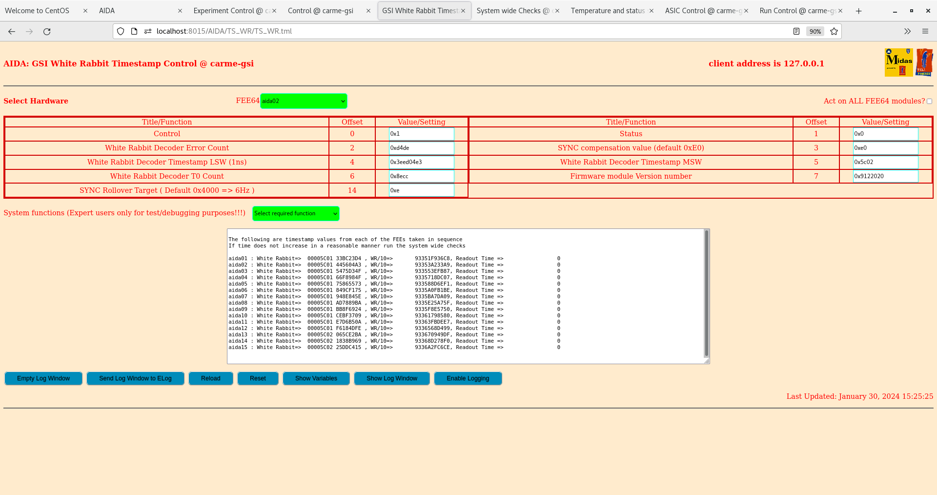
|
| Attachment 14: Screenshot_from_2024-01-30_15-33-37.png
|

|
| Attachment 15: Screenshot_from_2024-01-30_15-38-08.png
|

|
| Attachment 16: Screenshot_from_2024-01-30_15-39-28.png
|
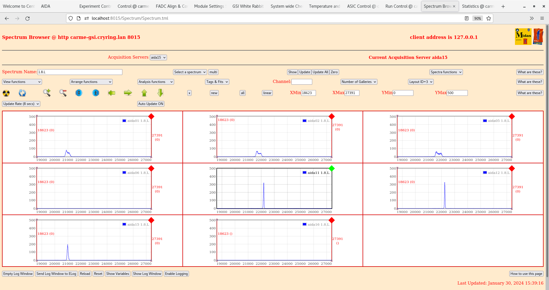
|
| Attachment 17: Screenshot_from_2024-01-30_15-43-00.png
|

|
| Attachment 18: Screenshot_from_2024-01-30_15-46-32.png
|

|
| Attachment 19: Screenshot_from_2024-01-30_16-01-08.png
|

|
| Attachment 20: Screenshot_from_2024-01-30_16-03-27.png
|

|
| Attachment 21: Screenshot_from_2024-01-30_16-08-50.png
|

|
| Attachment 22: Screenshot_from_2024-01-30_16-09-27.png
|
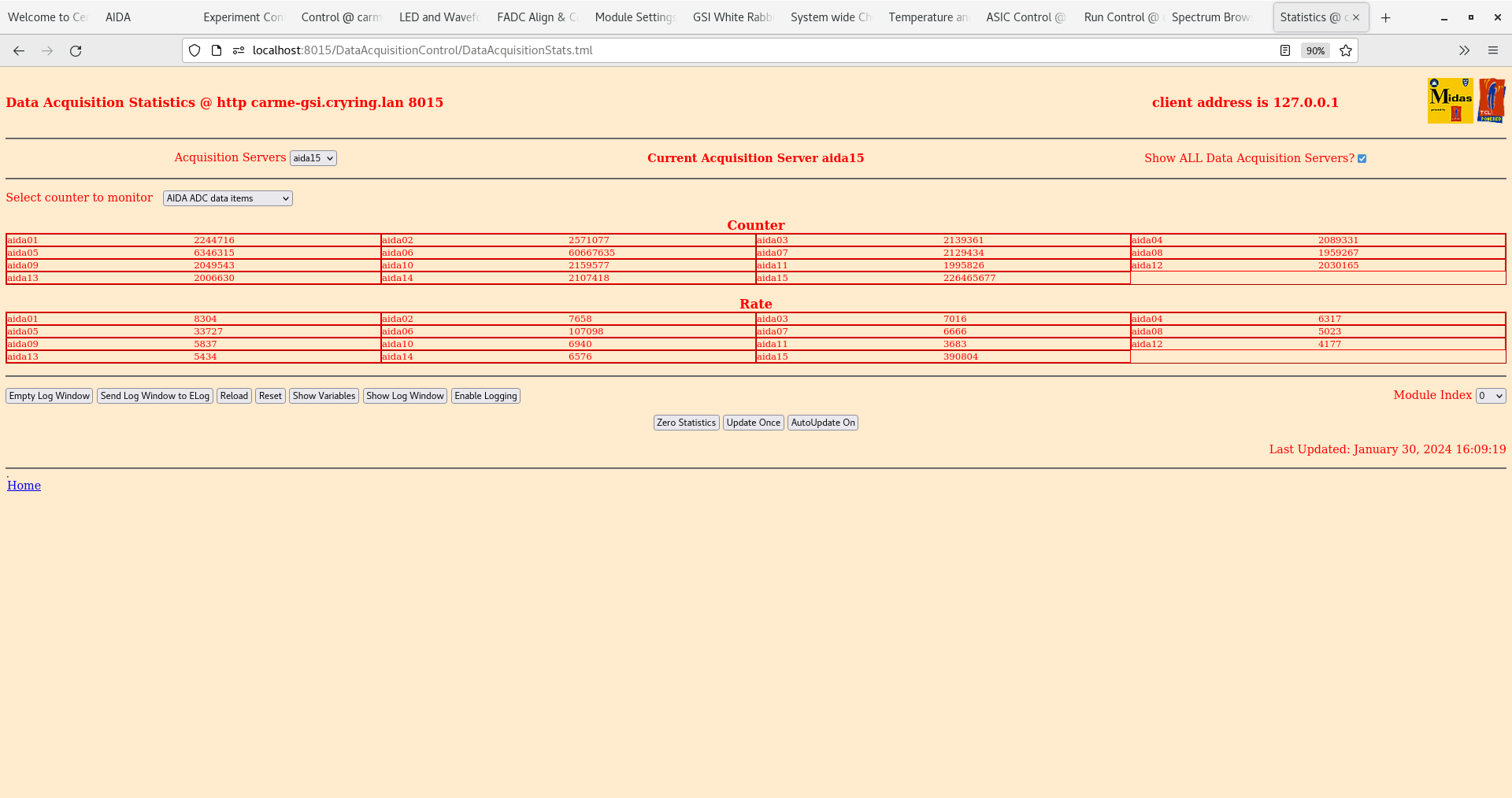
|
| Attachment 23: Screenshot_from_2024-01-30_16-48-21.png
|

|
| Attachment 24: Screenshot_from_2024-01-30_16-49-38.png
|

|
| Attachment 25: Screenshot_from_2024-01-30_16-50-41.png
|

|
| Attachment 26: Screenshot_from_2024-01-30_16-51-51.png
|

|
| Attachment 27: Screenshot_from_2024-01-30_17-35-01.png
|

|
| Attachment 28: Screenshot_from_2024-01-30_17-36-01.png
|
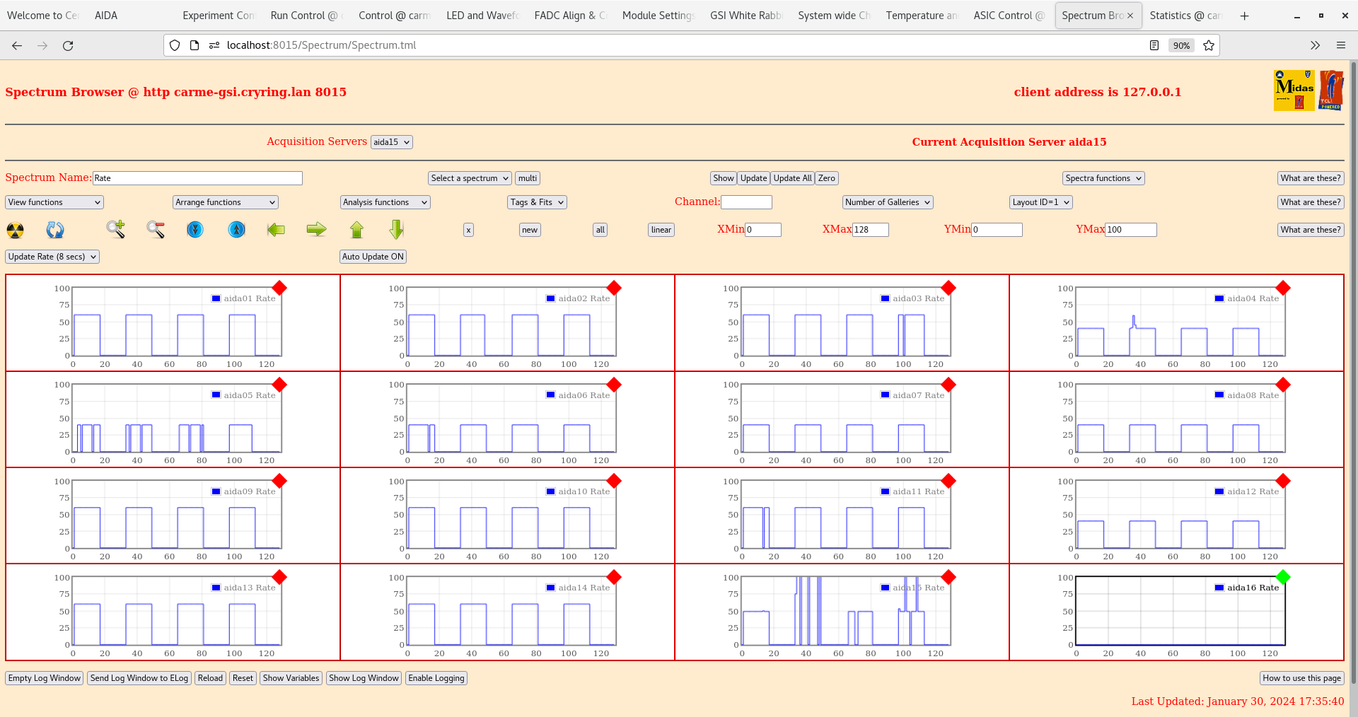
|
| Attachment 29: Screenshot_from_2024-01-30_17-36-57.png
|

|
| Attachment 30: Screenshot_from_2024-01-30_17-39-02.png
|

|
| Attachment 31: Screenshot_from_2024-01-30_17-40-05.png
|
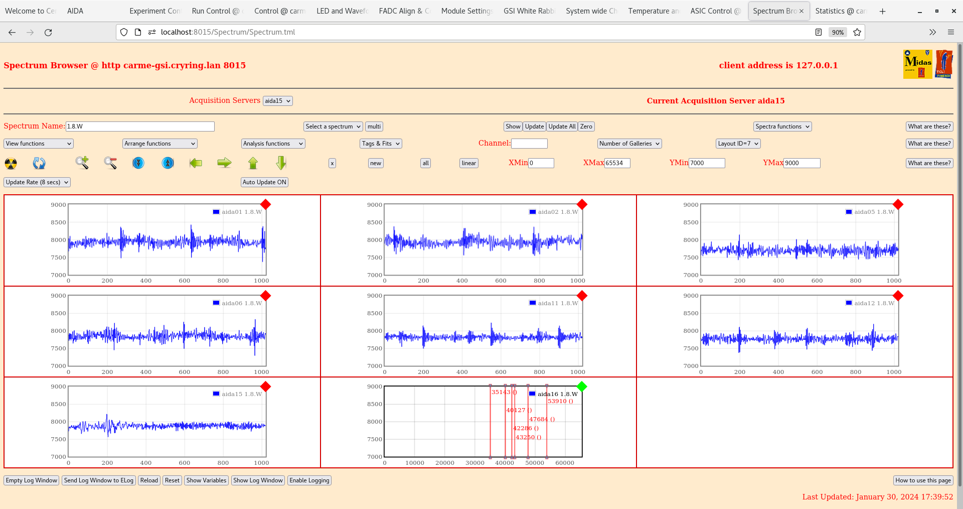
|
| Attachment 32: Screenshot_from_2024-01-30_17-41-19.png
|
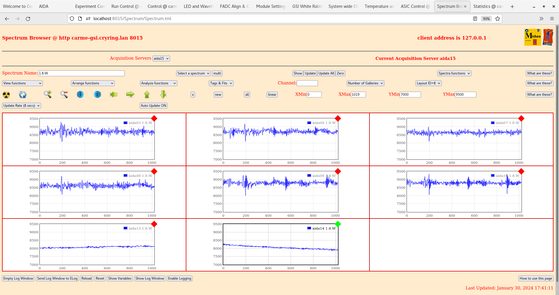
|
|
480
|
Mon Jan 29 15:32:08 2024 |
TD, JM | Monday 29 January contd. |
Test + and test - daisy chain cabling extended from DSSSD #1 to #2 to DSSSD #1 to DSSSD #4
 terminated by 50 Ohm at end of daisy chain

Grounding cabling extended from DSSSD #1 ( only ) to DSSSD #1 to DSSSD #4
 grounding cables daisy-chained between 4x adaptor PCBs of each DSSSD - no inter-DSSSD grounding cables

DSSSD#1 bias cable SHV-Lemo 00.250 ( to p+n bias adaptor PCB )
DSSSD#2 - DSSSD #4 bias cables SHV - 2x Lemo 00.250 ( to p+n/n+n bias adaptor PCBs )

LK1 fitted for DSSSD #1 & #2 n+n Ohmic side bias adaptor PCBs
LK2 not fitted on any adaptor PCBs? to be checked

CAEN N1419ET internal jumper fitted ( non-floating outputs )? to be checked

16.54 DSSSD bias OK - see attachment 1

      FEE64 temperatures - attachment 2
       aida06 ASIC temp low

      System wide checks and WR - attachments 3-6
       global clock status aid04 0x6, aida06 0x4
       multiple FPGA timestamp and WR decoder errors for MACBs 4 and 5 ( of 5 )

       WR timestamps OK for aida01-aida08 ( w/ MACB firmware version 04/20 )

     ADC data item stats - attachment 7
      all rates consistent with 50Hz pulser *except*
       aida11 global clock fail
       aida07 no boot
       aida16 no power
       aida06 ?
       aida15 faulty asic #2

     per FEE64 Rate spectra - attachment 8

     per p+n and n+n FEE64 1.8.L spectra - attachments 9-12
      Pulser peak width p+n side 52 ch FWHM ( aida12 ), n+n side 70 ch FWHM ( aida14 )

per p+n and n+n 1.8.W spectra - 20us FSR - attachments 13-16 |
| Attachment 1: Screenshot_from_2024-01-29_16-54-37.png
|

|
| Attachment 2: Screenshot_from_2024-01-29_16-56-12.png
|
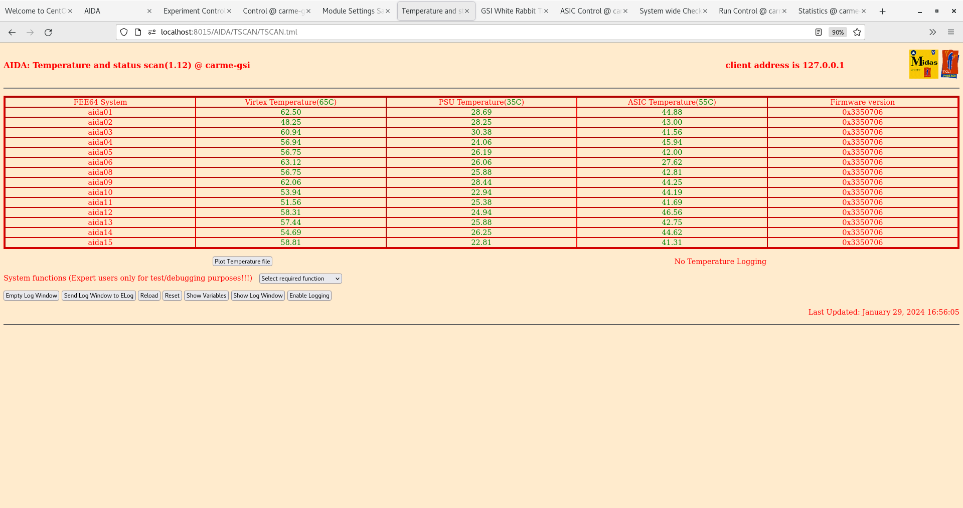
|
| Attachment 3: Screenshot_from_2024-01-29_16-55-07.png
|
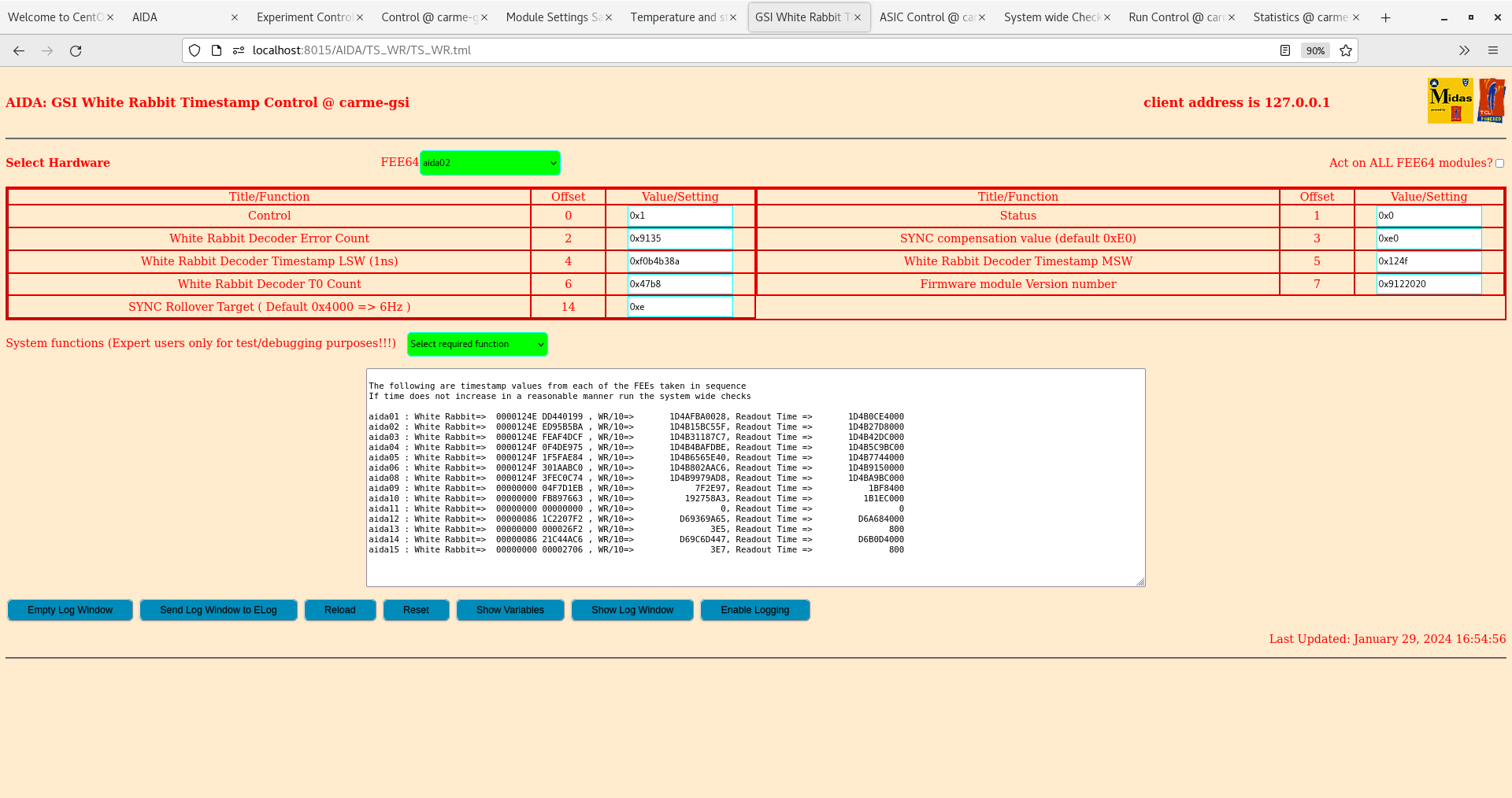
|
| Attachment 4: Screenshot_from_2024-01-29_16-55-24.png
|

|
| Attachment 5: Screenshot_from_2024-01-29_16-55-39.png
|
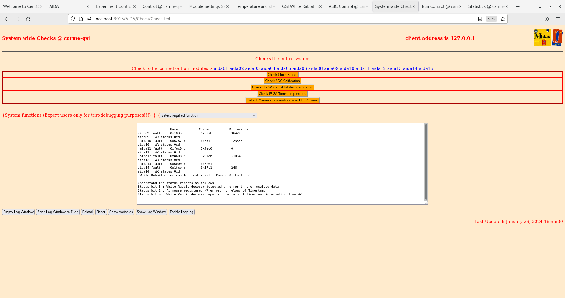
|
| Attachment 6: Screenshot_from_2024-01-29_16-55-53.png
|

|
| Attachment 7: Screenshot_from_2024-01-29_16-59-13.png
|

|
| Attachment 8: Screenshot_from_2024-01-29_17-03-10.png
|
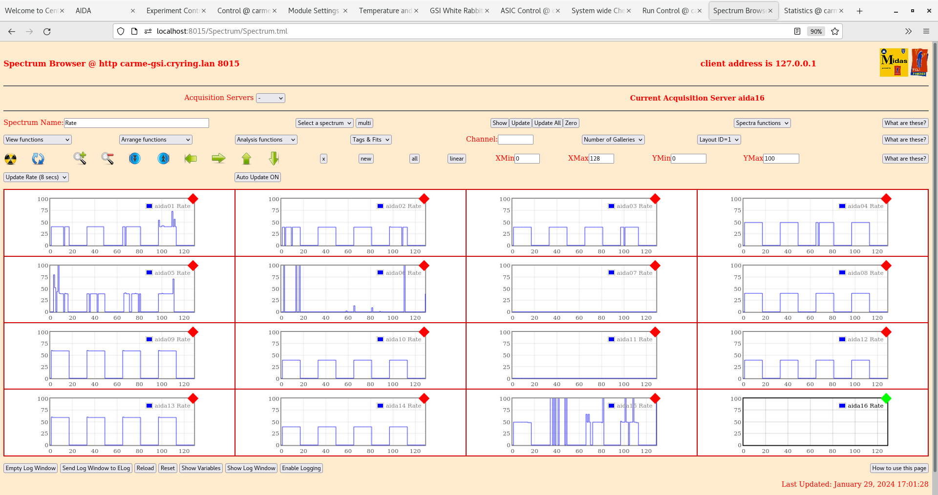
|
| Attachment 9: Screenshot_from_2024-01-29_17-05-44.png
|

|
| Attachment 10: Screenshot_from_2024-01-29_17-06-15.png
|

|
| Attachment 11: Screenshot_from_2024-01-29_17-08-53.png
|

|
| Attachment 12: Screenshot_from_2024-01-29_17-09-23.png
|

|
| Attachment 13: Screenshot_from_2024-01-29_17-11-01.png
|

|
| Attachment 14: Screenshot_from_2024-01-29_17-11-39.png
|
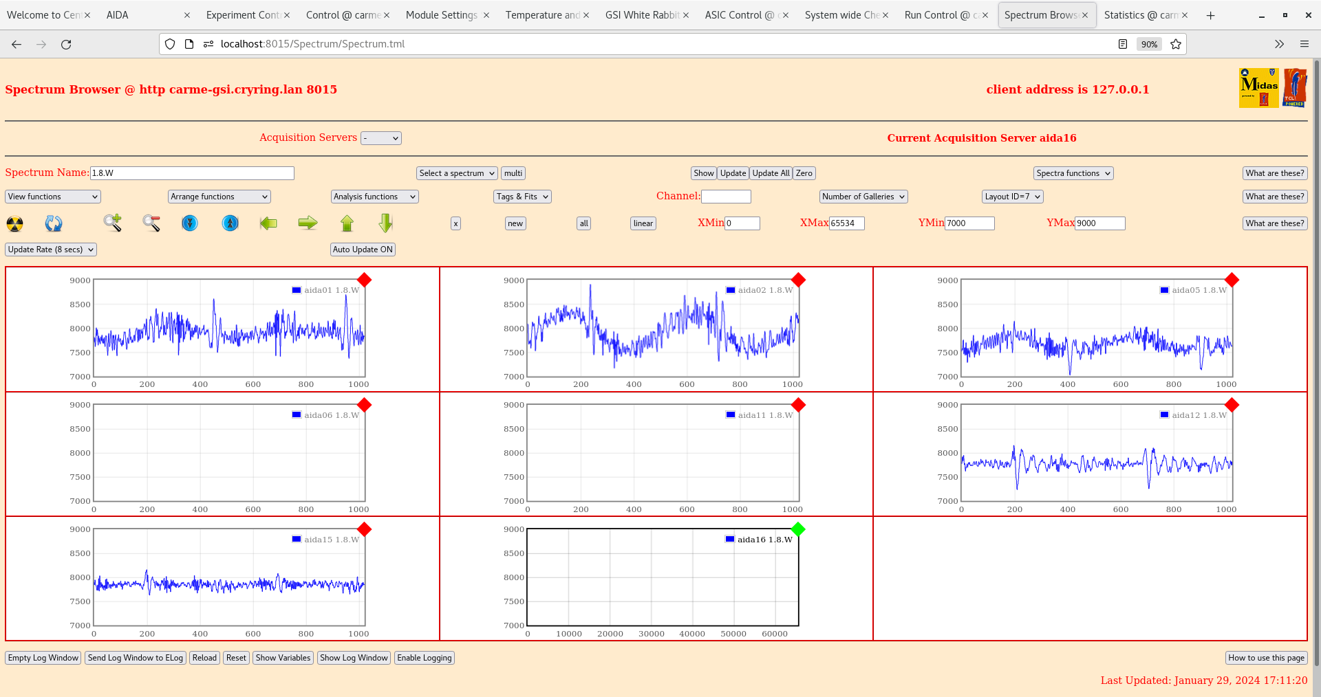
|
| Attachment 15: Screenshot_from_2024-01-29_17-12-26.png
|

|
| Attachment 16: Screenshot_from_2024-01-29_17-13-06.png
|
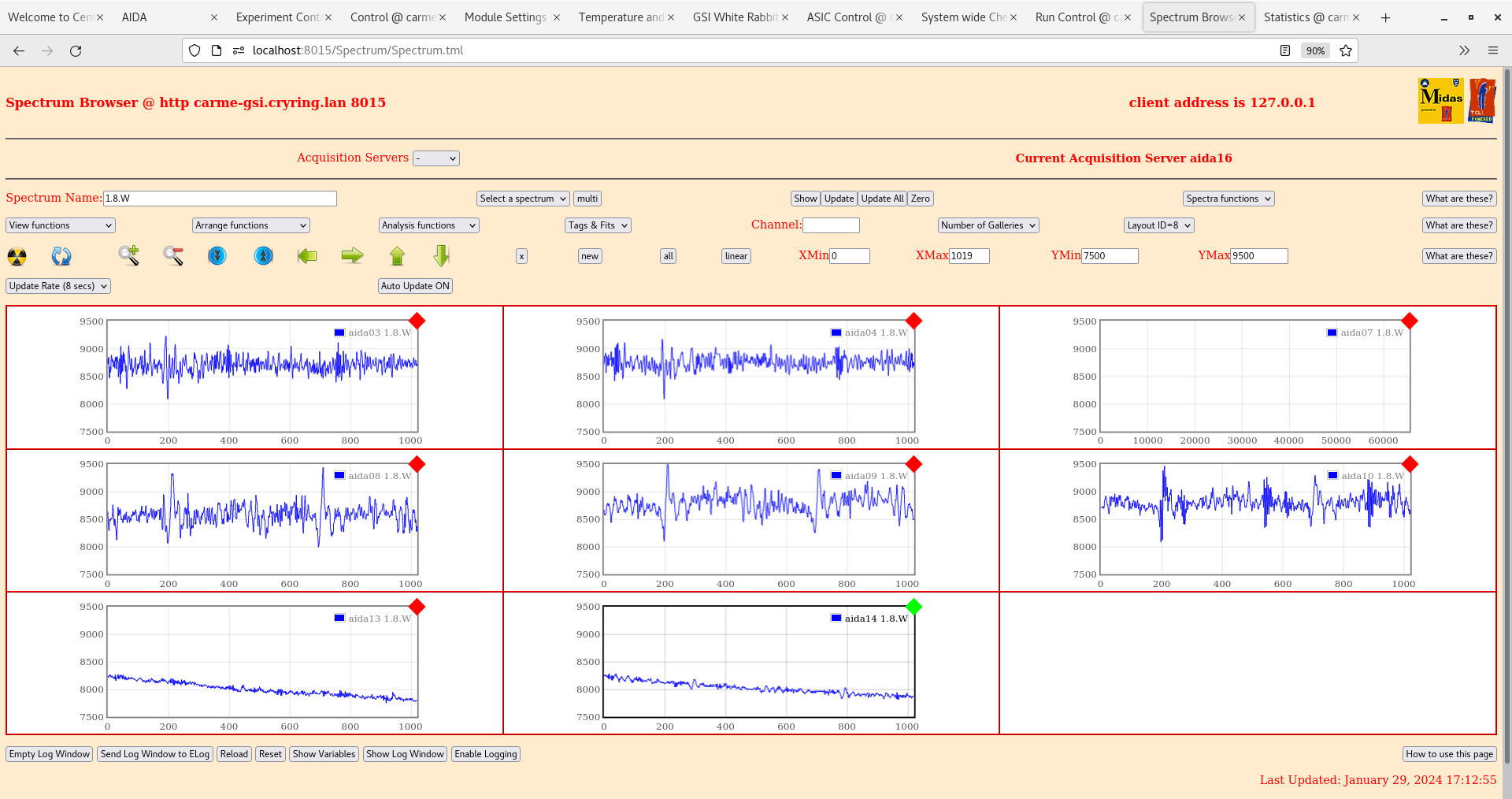
|
|
479
|
Mon Jan 29 08:52:07 2024 |
TD JM | Monday 29 January |
09.50 CARME IE514 5.1e-11 mbar ( ambient temperature 16 deg C )

10.24 DSSD bias OK - attachment 1

10.40 MACB configuration

      1              2      3      4      5

mode  0x3            0x3    0x3    0x3    0x3

      from VETAR2    from 1 from 1 from 1 from 1
      to 2           aida01 aida05 aida09 aida13
      to 3           :      :      :      :
      to 4           :      :      :      :
      to 5           aida04 aida08 aida12 aida16

WR emulator cables connected to MACB #1 rear panel

DAQ reset and DAQ setup between each test below - the FEE64s were NOT power cycled between tests


      Per https://elog.ph.ed.ac.uk/CARME/478 test WR

      connecting/disconnecting HDMI cable from VETAR2 to MACB level 0 input was tested 20.1.24 per https://elog.ph.ed.ac.uk/CARME/477

      With VETAR2 abd all MACB mode sttings 0x3 observe same WR issues as previously

      Noted clock & sync cables from WR emulator were swapped
      ( pay attention to SMA cables cf. Zybo board *not* NIM module as shown in https://elog.ph.ed.ac.uk/DESPEC/517 )

      Change MACB level 0 mode from 0x3 to 0xd - all other MACBs mode 0x3
      HDMI cabkle from VETAR2 to MACB level 0 input disconnected

      System wide checks - global clocks all fail - see attachments 2-5


11.14 Reduce MAC config to MACB level 0 plus one MACB connected to FEE64s aida01-aida4
      All MACB modes 0x3

      System wide checks aida01-aida04 OK. Same problem observed with WR timestamp for aida01-aida04

      See attachments 6-9

11.22 Reduce MAC config to one MACB connected to FEE64s aida01-aida4
      MACB mode 0x3

      System wide checks aida01-aida04 OK. Same problem observed with WR timestamp for aida01-aida04

      See attachments 10-13

11.26 One MACB config using MACB 2 of 5 in NIM bin connected to FEE64s aida01-aida4
      MACB mode 0x3

      System wide checks aida01-aida04 OK. Same problem observed with WR timestamp for aida01-aida04

      See attachments 14-17

11.36 Connect VETAR2 output directly to aida09

      System wide checks for aida09 OK.Valid WR timestamp appears to be generated.

      See attachments 18-20

      Check NIM bin with MACBs etc
        +/-6V, 12V and 24V lines OK

11.42 Connect VETAR2 to MACB 1 of 5 ( mode 0x3 )
      Connect aida09 to MACB 1 of 5
      Global clock OK. WR decoder status error 0xd reported for aida09. Valid WR timestamp for aida09.

      See attachments 21-24

11.53 Connect VETAR2 to MACB 1 of 5 ( mode 0x3 )
      Connect aida09-aida12 to MACB 1 of 5
      Global clock OK. WR decoder status error 0xd reported for aida09-aida12. WR timestamps for aida09-aida12 very different - aida10 might be correct timestamp?

      See attachments 25-28

11.53 Connect VETAR2 to MACB 2 of 5 ( mode 0x3 )
      Connect aida09-aida12 to MACB 2 of 5
      Global clock OK. WR decoder status error 0xd reported for aida09-aida12. WR timestamps for aida09-aida12 very different - aida10 & 11 approx correct but 11 has
lower timestamp than 10 so probably not quite right

      See attachments 29-32


15.00 Per https://elog.ph.ed.ac.uk/CARME/478 systematically test 1x MACB configurations to find 'working' MACBs

      Identify 3x MACB modules which produce sensible WR timestamps - all labelled ' firmware version 04/20 '.
      The other 5x MACBs are either unlabelled or labelled unknown.

      MACB configuration now uses 04/20 MACBs for MACBs 1-3 and unlabelled 2xMACBs fpr MACBs 4-5
      aida01-aida08 should produce WR timestamps OK

Will attempt to update firmwre of 5x MACBs tomorrow pm with NH |
| Attachment 1: Screenshot_from_2024-01-29_10-24-10.png
|
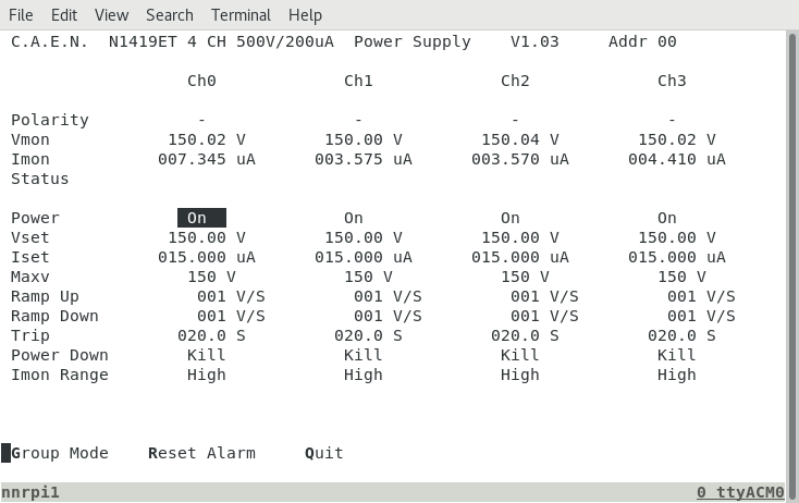
|
| Attachment 2: Screenshot_from_2024-01-29_11-05-18.png
|

|
| Attachment 3: Screenshot_from_2024-01-29_11-05-49.png
|

|
| Attachment 4: Screenshot_from_2024-01-29_11-08-15.png
|

|
| Attachment 5: Screenshot_from_2024-01-29_11-08-41.png
|

|
| Attachment 6: Screenshot_from_2024-01-29_11-20-44.png
|
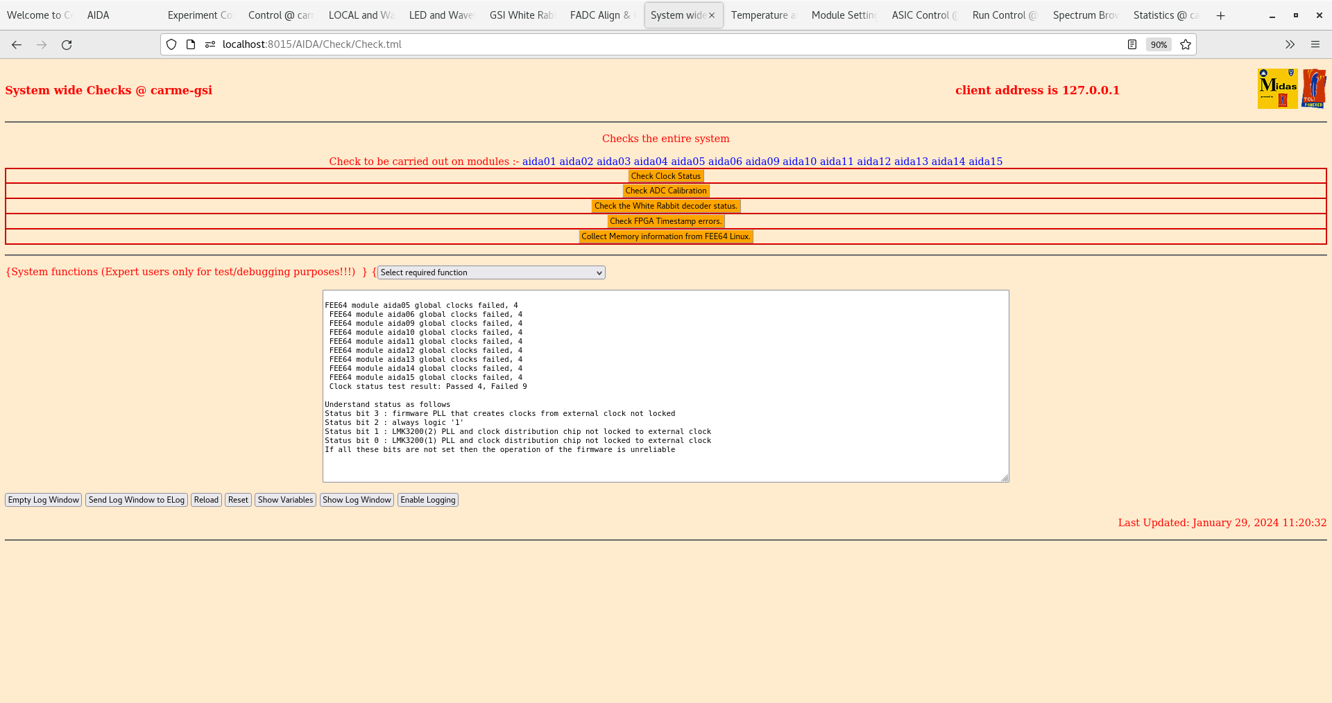
|
| Attachment 7: Screenshot_from_2024-01-29_11-21-07.png
|

|
| Attachment 8: Screenshot_from_2024-01-29_11-21-29.png
|
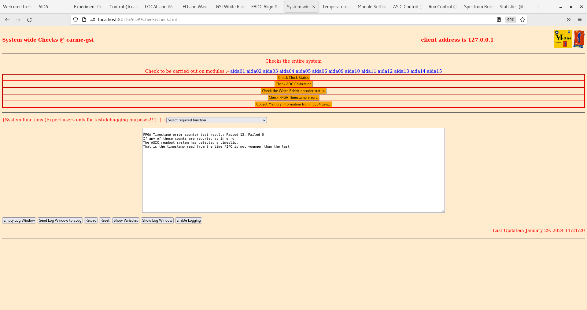
|
| Attachment 9: Screenshot_from_2024-01-29_11-22-00.png
|

|
| Attachment 10: Screenshot_from_2024-01-29_11-28-20.png
|

|
| Attachment 11: Screenshot_from_2024-01-29_11-28-40.png
|

|
| Attachment 12: Screenshot_from_2024-01-29_11-28-52.png
|

|
| Attachment 13: Screenshot_from_2024-01-29_11-29-26.png
|

|
| Attachment 14: Screenshot_from_2024-01-29_11-33-16.png
|

|
| Attachment 15: Screenshot_from_2024-01-29_11-33-30.png
|

|
| Attachment 16: Screenshot_from_2024-01-29_11-33-43.png
|

|
| Attachment 17: Screenshot_from_2024-01-29_11-34-15.png
|
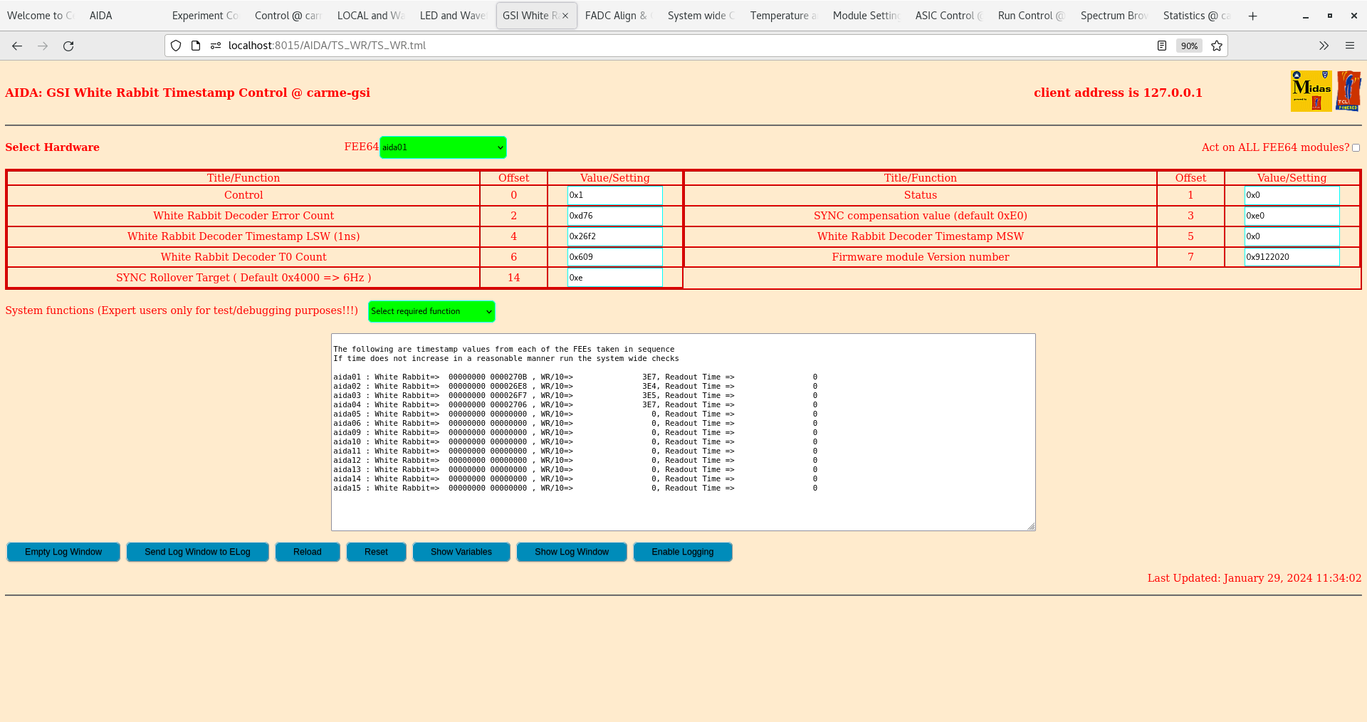
|
| Attachment 18: Screenshot_from_2024-01-29_11-40-51.png
|

|
| Attachment 19: Screenshot_from_2024-01-29_11-41-12.png
|

|
| Attachment 20: Screenshot_from_2024-01-29_11-41-59.png
|

|
| Attachment 21: Screenshot_from_2024-01-29_11-48-20.png
|

|
| Attachment 22: Screenshot_from_2024-01-29_11-48-41.png
|
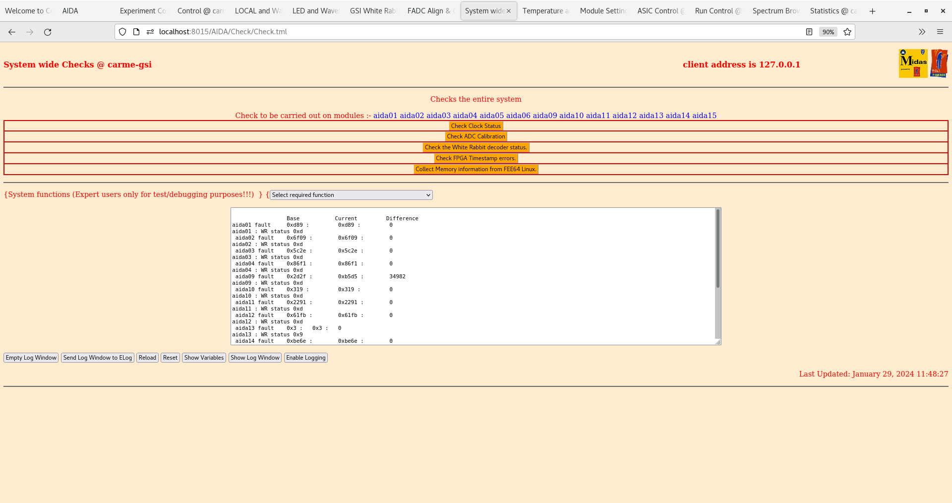
|
| Attachment 23: Screenshot_from_2024-01-29_11-48-58.png
|

|
| Attachment 24: Screenshot_from_2024-01-29_11-49-22.png
|
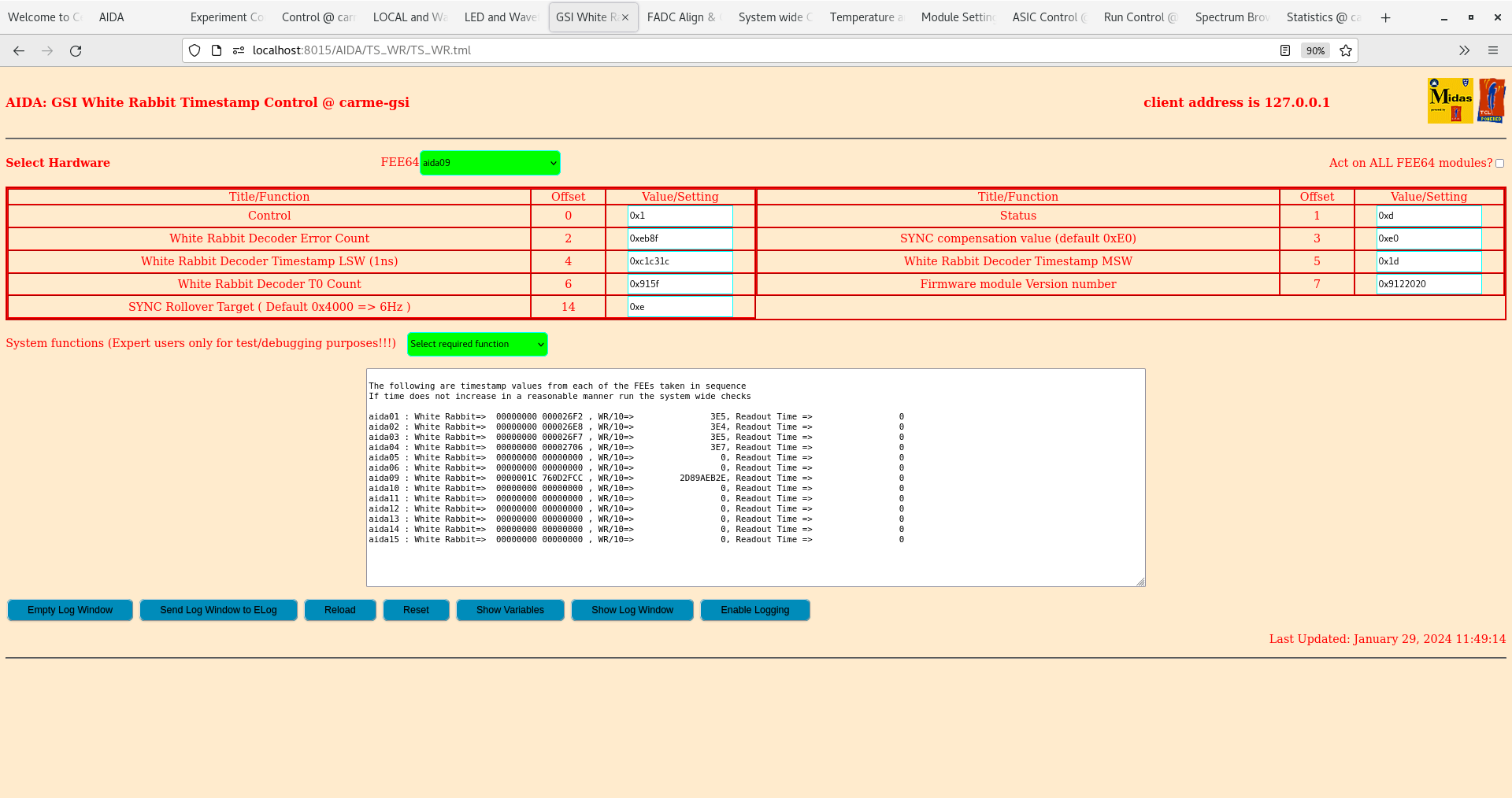
|
| Attachment 25: Screenshot_from_2024-01-29_11-57-41.png
|
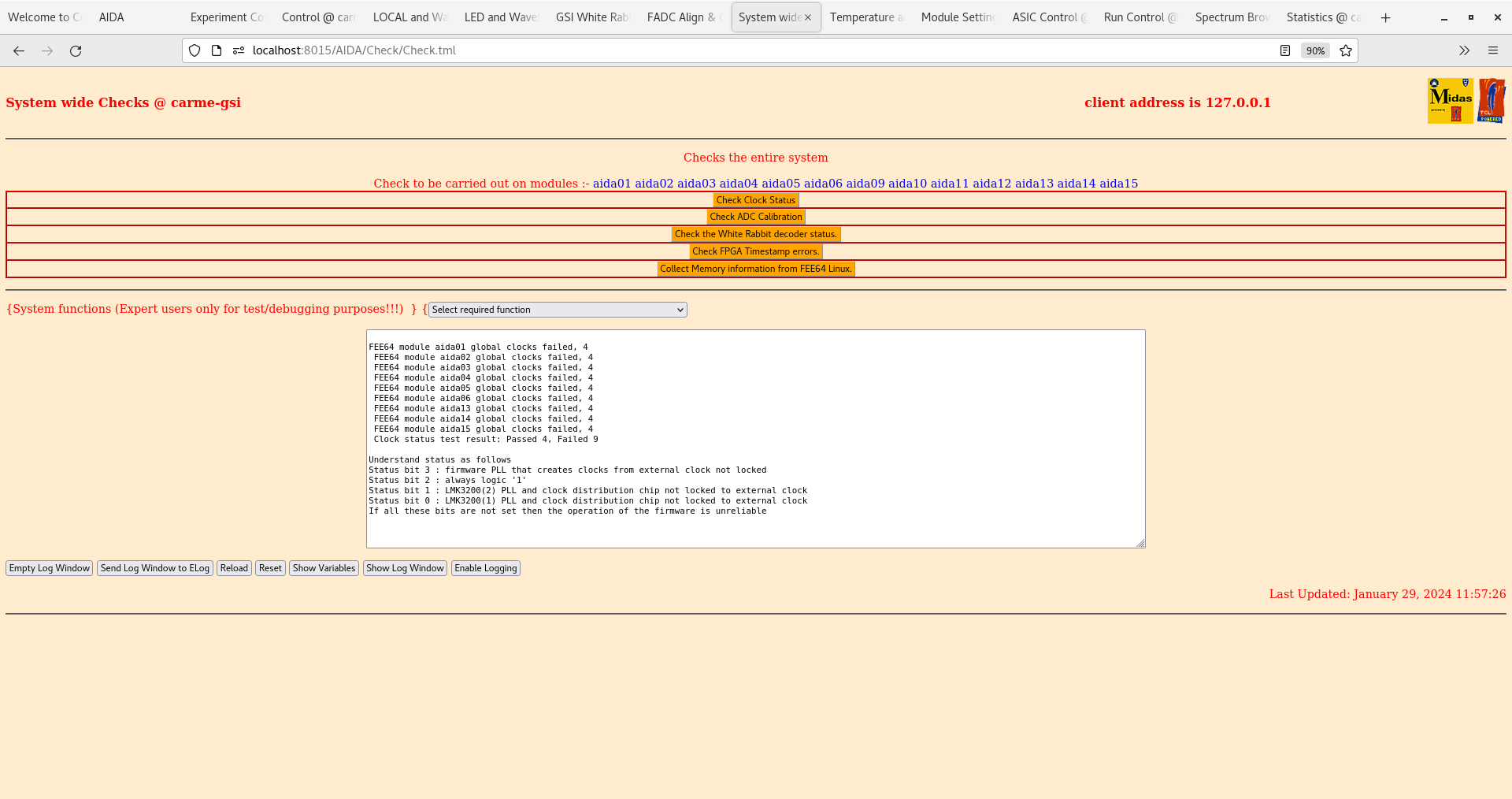
|
| Attachment 26: Screenshot_from_2024-01-29_11-58-11.png
|

|
| Attachment 27: Screenshot_from_2024-01-29_11-58-25.png
|

|
| Attachment 28: Screenshot_from_2024-01-29_11-59-11.png
|

|
| Attachment 29: Screenshot_from_2024-01-29_12-05-28.png
|

|
| Attachment 30: Screenshot_from_2024-01-29_12-05-59.png
|

|
| Attachment 31: Screenshot_from_2024-01-29_12-06-11.png
|

|
| Attachment 32: Screenshot_from_2024-01-29_12-07-03.png
|

|
|
478
|
Sat Jan 27 20:38:15 2024 |
PJCS | [INFO] Steps to diagnose White Rabbit problems |
This is a suggested sequence of actions to help with the current problem with the White Rabbit timestamp distribution. Test the system between each intervention. If a test provides an answer to the problem then proceed accordingly rather than continue with the suggestions.
- Please sketch the current MACB wiring.
- Unplug and replug the connectors of the VETAR HDMI connecting cable. If possible clean the pcb and cable HDMI connectors with contact cleaner.
- Disconnect the VETAR and connect the Emulator. If the clocks are not correct then at the Local and Waveform control page change the entry for LMK03200 control register at offset 5 to 0xB. If clocks are now ok then repeat for all the FEEs. Be aware that this value will be set back to 0x1B during SETUP. If the Emulator fails then continue with VETAR and setting 0x1B.
- Connect one or more FEE64 to the base MACB.
- Change the base MACB and repeat the test above.
- Connect a FEE to the VETAR direct.
I am at present unable to advise further. However should there be more then I will update this entry. |
|
477
|
Mon Jan 22 16:29:31 2024 |
TD | Saturday 20 January |
11.00 No WLAN/WiFi
      came-gsi private LAN appears to be OK

      AIDA FEE64 power ON

11.09 FEE64 temps - attachment 1
      aida06 low, otherwise OK

11:10 CARME IE514 4.0e-11 mbar, temp unknown
      IE514 OFF

11.22 Detector bias ON - attachment 2
      found ch 2 up ramp set to 63V/s! changed to 1V/s

11.30 system wide checks OK except
      aida02 & aida06 fail WR decoder status

      WR ts control - attachments 3-4


12.02 ASIC settings updated for aida09-aida16
      ASIC settings DB key 2024Jan20-12:02:08

      Unable to save DB key to Options - use ASIC settings restore as workaround

12.30 Layouts for 16x FEE64s created - directory ~/LayOut/16xFEE64
      Note layouts include spectra from aida07, aida08 and aida16 so an error message will be generated but it can be ignored


12.40 per FEE64 Rate spectra - attachments 5-6
      per FEE64 p+n & nn 1.8.W spectra - attachments 7-8

12.57 per FEE64 p+n & n+n 1.8.W spectra 20us FSR - attachments 9-10

Test signals

EG&G Ortec 448 Pulser
Amplitude 90,000
attenuation x10
Normalise 5.00
t_r 100ns
tau_d 50us
Frequency 50Hz ( relay line freq )
Polarity +

test + direct from 448, test - from Cooknell SA1 Sum & Invert

Test + daisy chain -> aida01 - aida02 - aida05 - aida06 - 50 Ohm
Test - daisy chain -> aida03 - aida04 - aida07 - aida08 - 50 Ohm

aida08 ( DSSSD #2 n+n Ohmic bias ) LK2 removed, LK1 added
aida04 ( DSSSD #1 n+n Ohmic bias ) no LK2 fitted, LK1 added

DSSSD#1 SHV - 2x Lemo 00.250 cable replaced by standard SHV - BNC/BNC Lemo-00.250 coaxial cable

Adaptor PCB ground daisy chain aida01 - aida02 - aida03 - aida04

DSSSD#2 - DSSSD#4 HV cabling unchanged

15.30 Power ON
      System wide checks OK except
          aida02 fail WR decoder status - attachment 11

      FEE64 temperatures - attachment 12
       aida06 ASIC temp low

      DSSSD bias - attachment 13

      ADC data item stats - attachment 14
       slow comparator 0x64

      per FEE64 Rate and 1.8.W 20us FSR spectra - attachments 15-17

16.00 per FEE64 rate spectra - attachment 18

16.15 per FEE64 Rate and 1.8.W 20us FSR spectra - attachments 19-21

17.36 Switch from VETAR2 ( all MACB modules mode 0x3 ) to NIM WR emulator ( root MACB module 0xd, all others 0x3 )
      All FEE64s fail Global clock and WR decoder - attachments 22-24
      WR timetsamp control - attachment 25


18.10 Noted MACB #4 mode actually set to 0x2 *not* 0x3 - changed to 0x3

      Re-test with VETAR2 WR - same behaviour as observed this morning - see attachments 26-30


Summary

n+n sides appear to be OK but noisy

no data observed from aida06 & aida11
 aida11 known to be disconnected from adaptor PCB

aida15 asic #2 may be faulty

aida01, aida05, aida12 - data suggest FEE64/adaptor PCB alignment issue ?

aida02, aida03, aida09, aida14 - data suggest adaptor PCB damaged pins ?


aida07 - network config issue ?

aida08 - not completing boot

need to attach sys console to aida07 & aida08 to diagnose problem. |
| Attachment 1: Screenshot_from_2024-01-20_11-10-03.png
|

|
| Attachment 2: Screenshot_from_2024-01-20_11-22-20.png
|
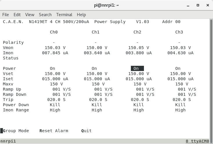
|
| Attachment 3: Screenshot_from_2024-01-20_11-31-31.png
|
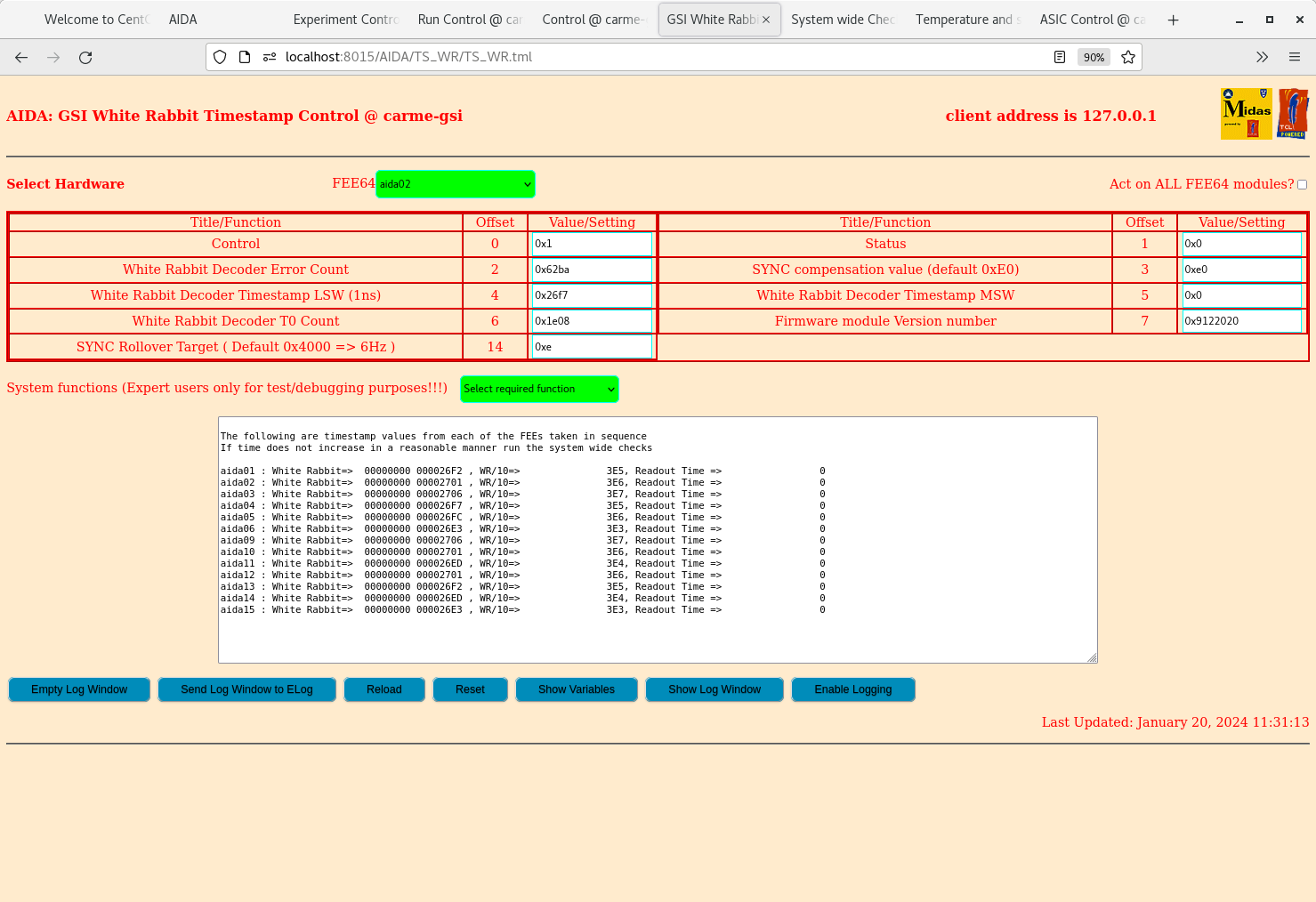
|
| Attachment 4: Screenshot_from_2024-01-20_11-31-39.png
|

|
| Attachment 5: Screenshot_from_2024-01-20_12-18-27.png
|

|
| Attachment 6: Screenshot_from_2024-01-20_12-18-37.png
|
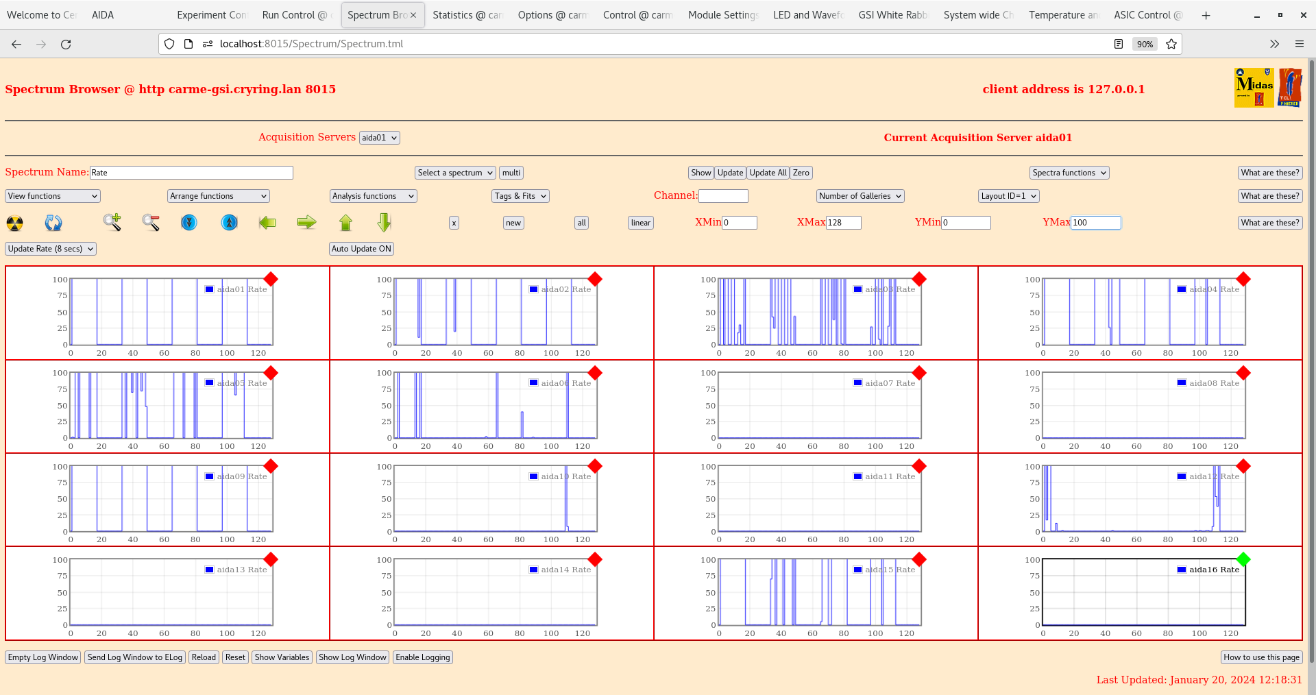
|
| Attachment 7: Screenshot_from_2024-01-20_12-44-07.png
|

|
| Attachment 8: Screenshot_from_2024-01-20_12-42-58.png
|

|
| Attachment 9: Screenshot_from_2024-01-20_12-59-12.png
|

|
| Attachment 10: Screenshot_from_2024-01-20_13-00-18.png
|
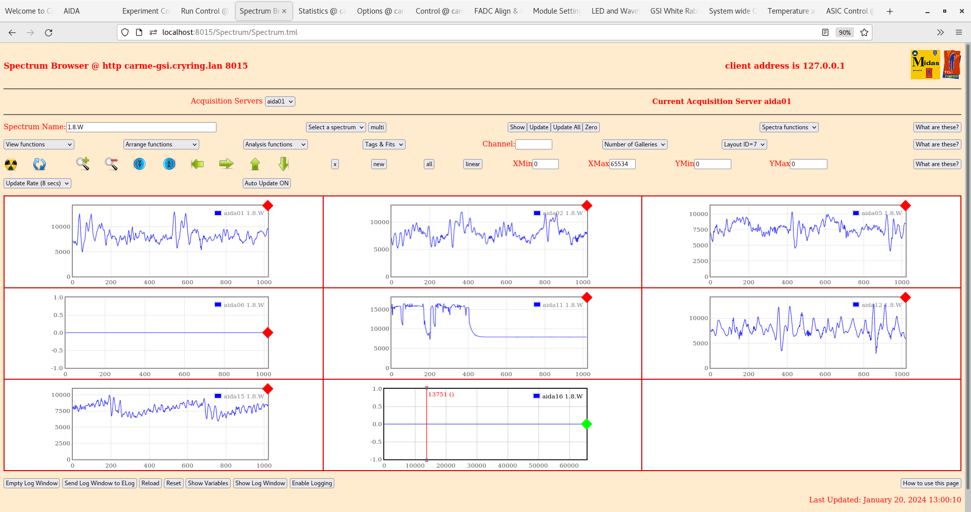
|
| Attachment 11: Screenshot_from_2024-01-20_15-30-48.png
|

|
| Attachment 12: Screenshot_from_2024-01-20_15-40-44.png
|
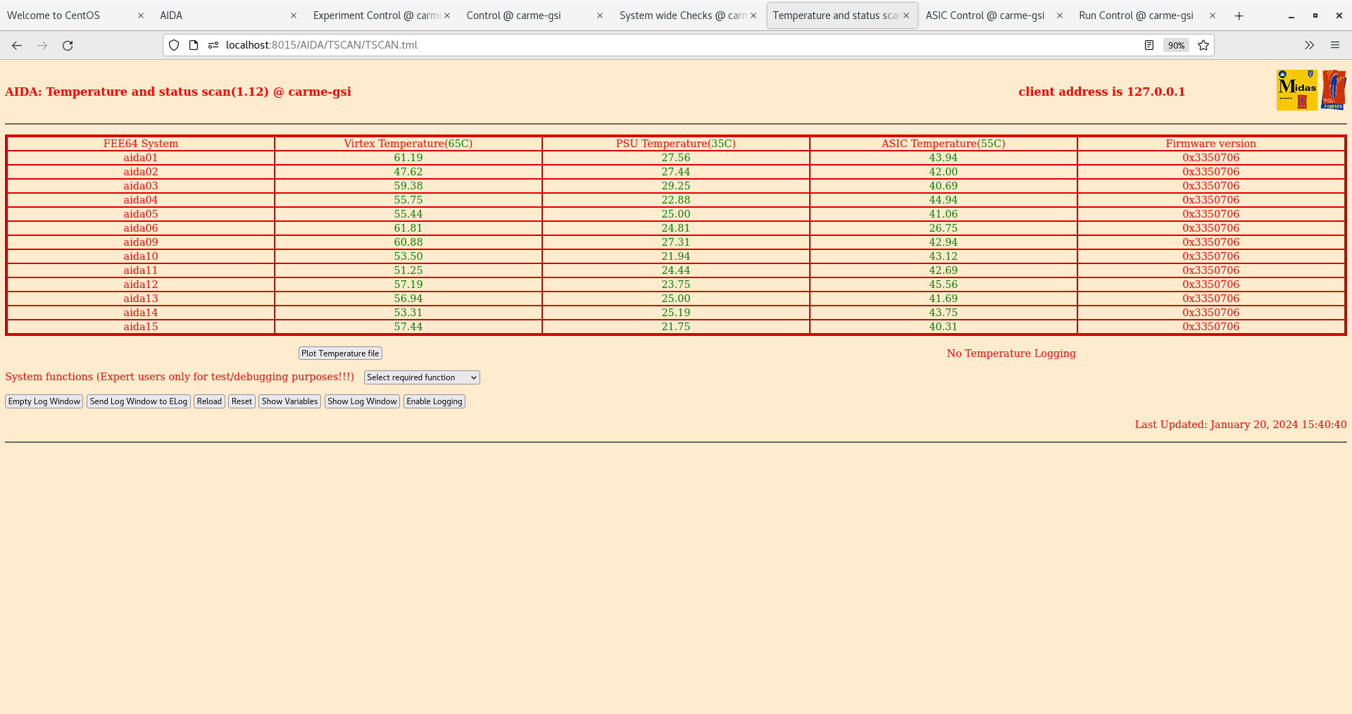
|
| Attachment 13: Screenshot_from_2024-01-20_15-40-58.png
|

|
| Attachment 14: Screenshot_from_2024-01-20_15-43-06.png
|

|
| Attachment 15: Screenshot_from_2024-01-20_15-44-18.png
|

|
| Attachment 16: Screenshot_from_2024-01-20_15-45-14.png
|

|
| Attachment 17: Screenshot_from_2024-01-20_15-45-47.png
|

|
| Attachment 18: Screenshot_from_2024-01-20_16-03-18.png
|

|
| Attachment 19: Screenshot_from_2024-01-20_16-15-24.png
|

|
| Attachment 20: Screenshot_from_2024-01-20_16-15-52.png
|
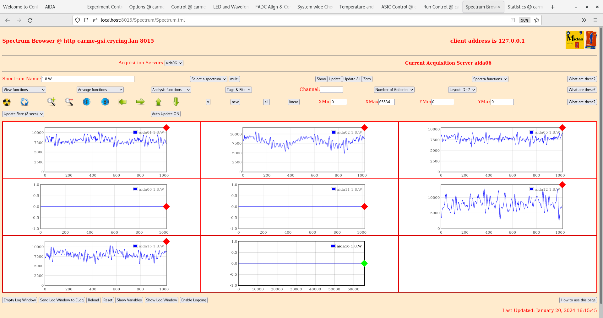
|
| Attachment 21: Screenshot_from_2024-01-20_16-16-37.png
|

|
| Attachment 22: Screenshot_from_2024-01-20_17-36-22.png
|
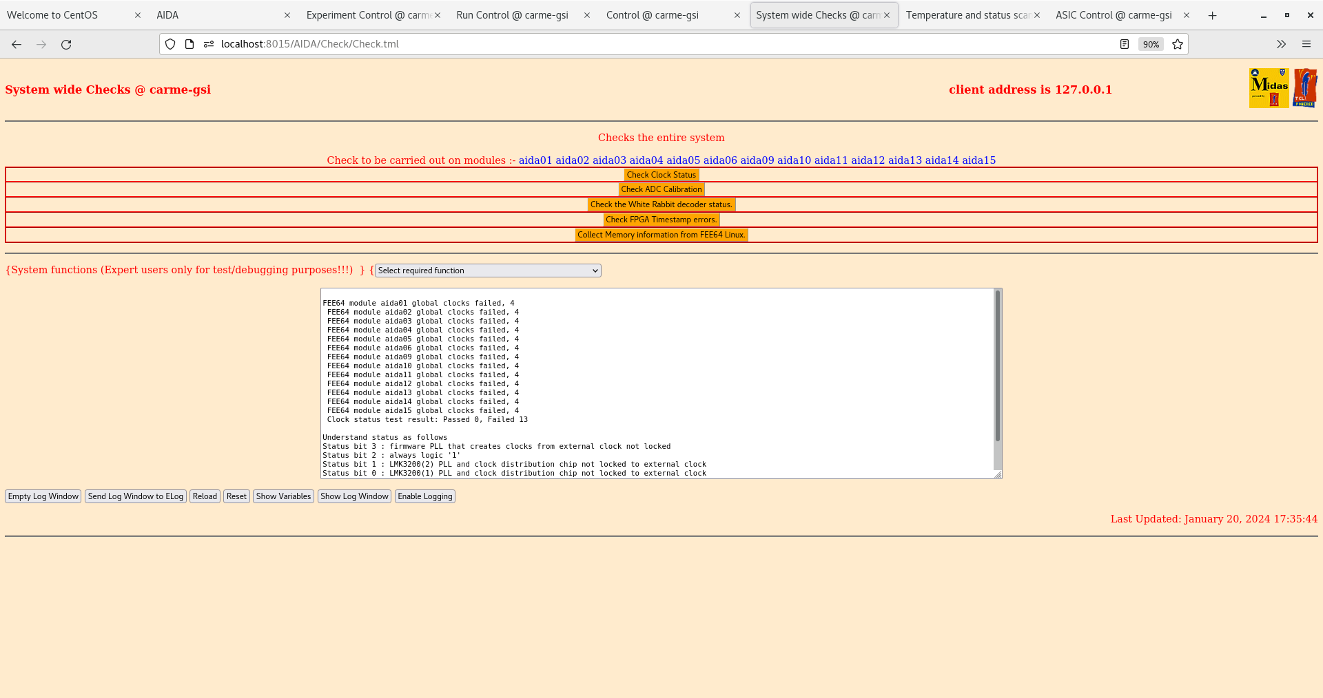
|
| Attachment 23: Screenshot_from_2024-01-20_17-36-28.png
|
|
| Attachment 24: Screenshot_from_2024-01-20_17-36-43.png
|

|
| Attachment 25: Screenshot_from_2024-01-20_17-38-22.png
|
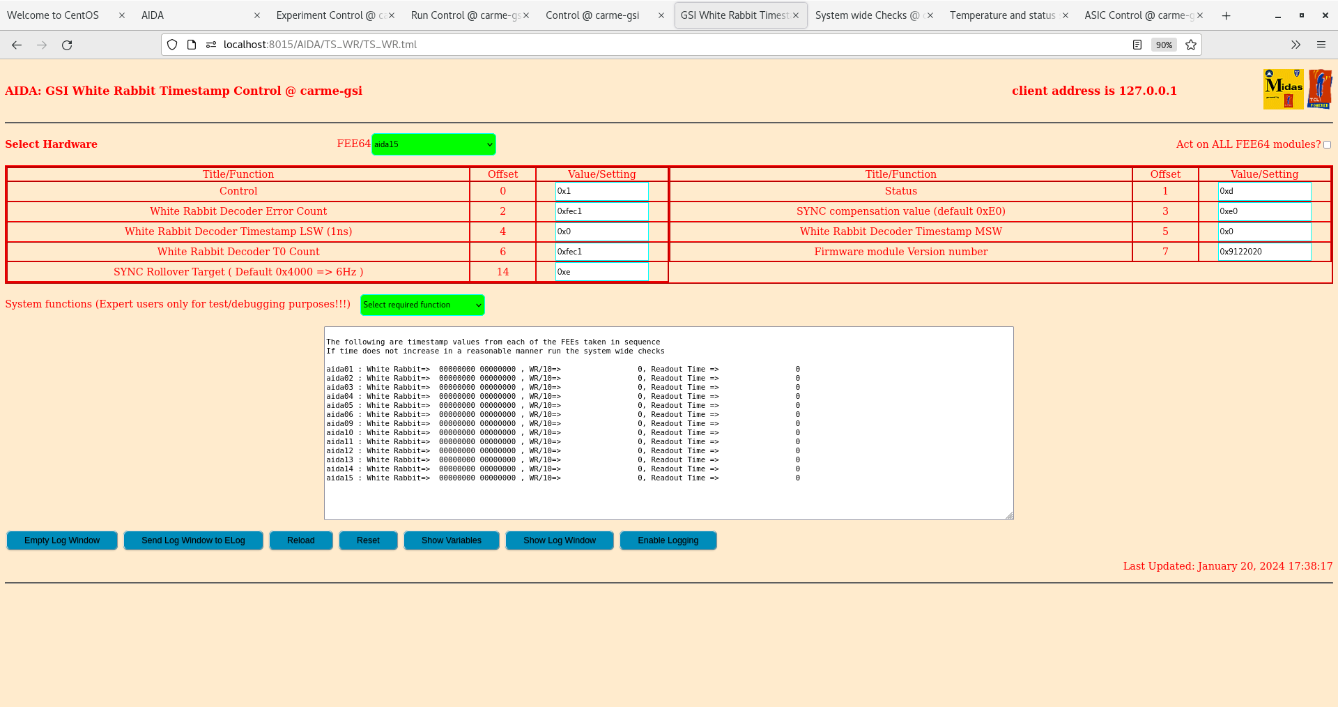
|
| Attachment 26: 1000009752.jpg
|

|
| Attachment 27: 1000009753.jpg
|
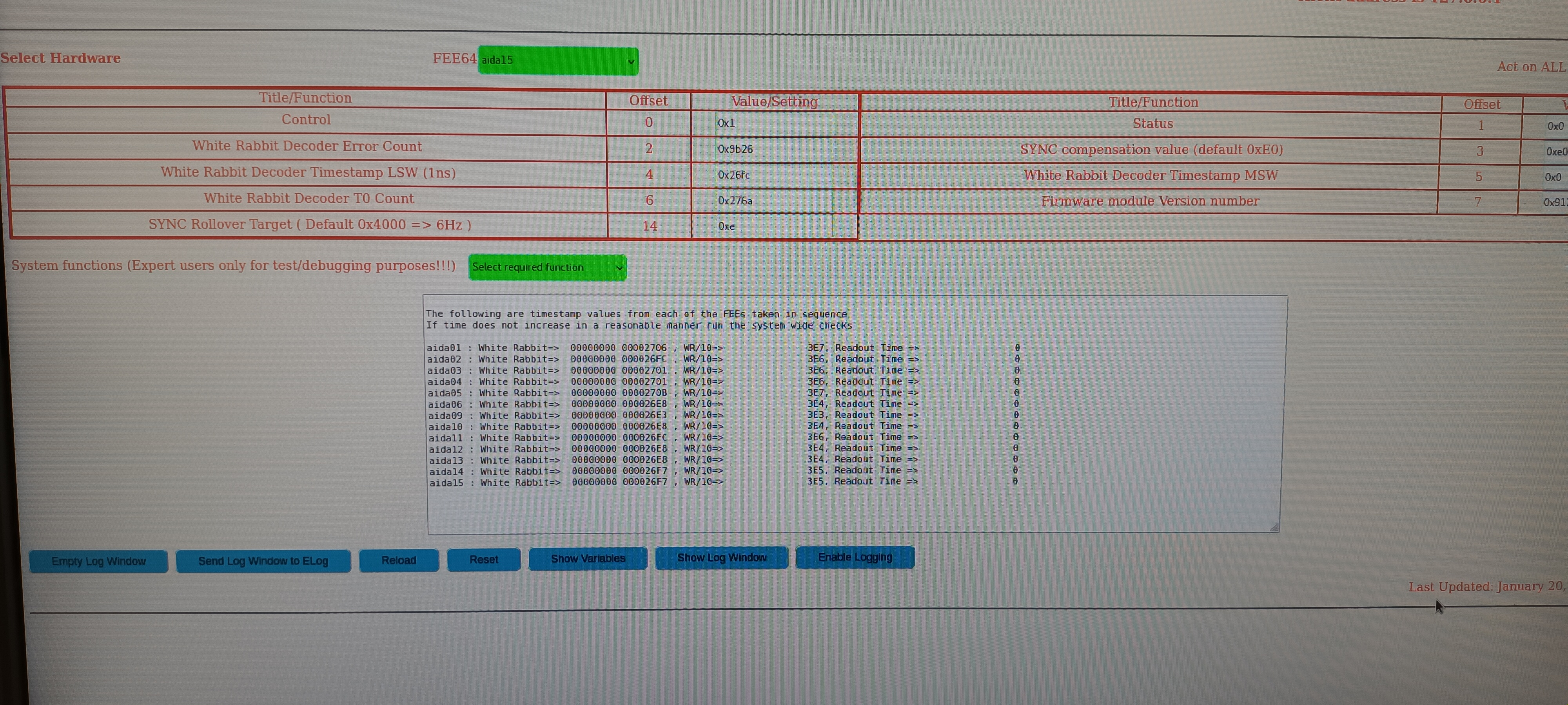
|
| Attachment 28: 1000009754.jpg
|

|
| Attachment 29: 1000009755.jpg
|
|
| Attachment 30: 1000009756.jpg
|

|
|
476
|
Fri Jan 19 11:17:50 2024 |
JG, TD | Friday 19 January |
12.20 CARME IE514 4.1e-11mbar, ambient temperature 16.7 deg C

      FEE64 cabling complete

      WR source - VETAR2 borrowed from Nik Kurz and opwerating standalone ( no BuTIS reference )
      All MACBs mode 0x3


15.20 Power ON FEE64s #1 - #15

      aida02 did not boot - /etc/dhcp/dhcpd.conf typo - fixed

      aida04 did not boot - AIDA FEE64 PSU output #4 fuses open circuit - fuses replaced from AIDA FEE64 PSU spare channel ( aida16 not connected yet ) - fixed

      aida07 did not boot - power OK - FEE64 comfort LEDs OK - network switch link LED OK - network config?

      aida08 boots - power OK - comfort LEDs OK - network switch link LED OK - requests RFS / but does not request RFS MIDAS - can ping aida08 OK, cannot telnet aida08 'connection refused'

      aida09 did not boot - FEE64 comfort LEDS OFF - swap FEE64 #9 & #10 power cables - aida09 boots OK, aida10 does not boot
      Restore #9 & #10 power cables - swap AIDA FEE64 outputs #1 & #2 ( aida09 & aida10 ) - aida09 boots OK
      Conclude AIDA FEE64 PSU ( no label ) output #1 is faulty. Replace AIDA FEE64 PSU ( label ISOL3 ). aida09 & aida10 boot OK

      aida15/aida16 MAC addresses were swapped in https://elog.ph.ed.ac.uk/CARME/467 - fixed

      aida01-aida06, aida09-aida15 boot OK - aida07 does not boot, aida08 does not complete boot

16.25 Configure MIDAS DEE64 servers aida01 - aida06, aida10 - aida15

      FEE64 temperatures - attachment 1
      aida06 looks low ( c. 25 deg C cf. c. 40 deg C )

      System wide checks - attachments 2-8
       aida02 fails WR decoder

      WR timestamps ( attachments 7 & 8 ) look odd/low - values always c. 0x2???


17.30 CARME IE514 OFF

      WR NIM emulator SMA cables to root MACB ( rear panel ) disconnected at front panel

      Power cycle FEE64s

      System wide checks & WR timestamp control - attachments 9-14
       no change

17.45 Detector bias -20, -100 & 150V - attachments 15-17
      CAEN N1419ET non-floating outputs ( to be checked ), HV cable SHV - 2x Lemo 00.250, LK1 not fitted

18.40 Detector bias -150V attachment 18


To Do
Check ASIC settings
Configure HV
Check LKs
Ground cabling
|
| Attachment 1: Screenshot_from_2024-01-19_16-30-27.png
|

|
| Attachment 2: Screenshot_from_2024-01-19_16-23-24.png
|

|
| Attachment 3: Screenshot_from_2024-01-19_16-23-33.png
|

|
| Attachment 4: Screenshot_from_2024-01-19_16-23-51.png
|

|
| Attachment 5: Screenshot_from_2024-01-19_16-24-02.png
|

|
| Attachment 6: Screenshot_from_2024-01-19_16-24-07.png
|

|
| Attachment 7: Screenshot_from_2024-01-19_16-24-44.png
|

|
| Attachment 8: Screenshot_from_2024-01-19_16-31-32.png
|

|
| Attachment 9: Screenshot_from_2024-01-19_17-48-30.png
|
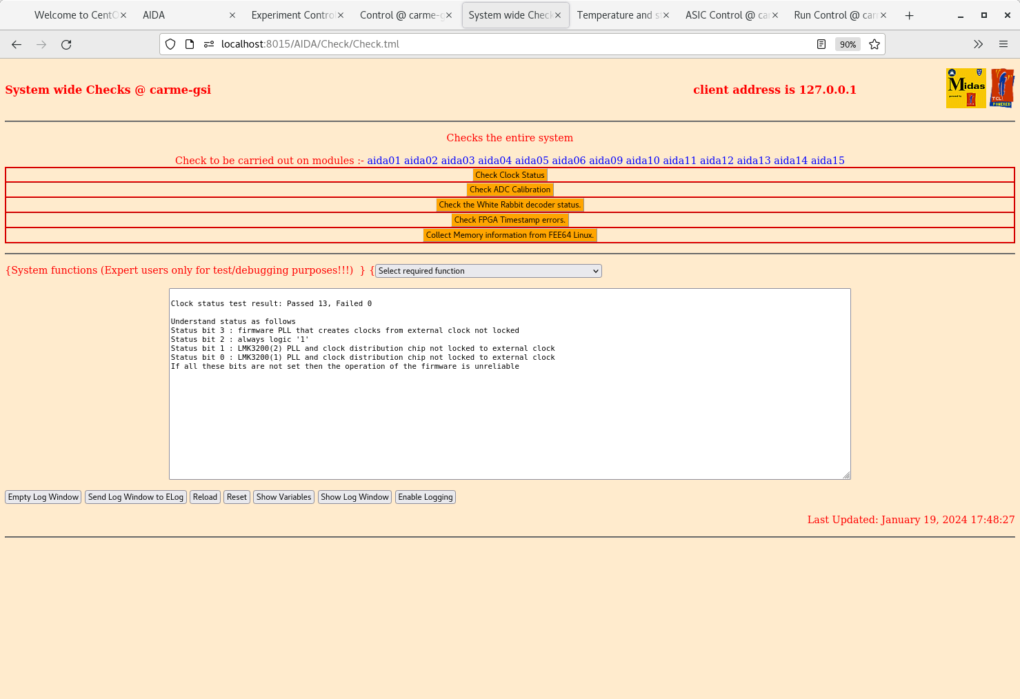
|
| Attachment 10: Screenshot_from_2024-01-19_17-48-38.png
|
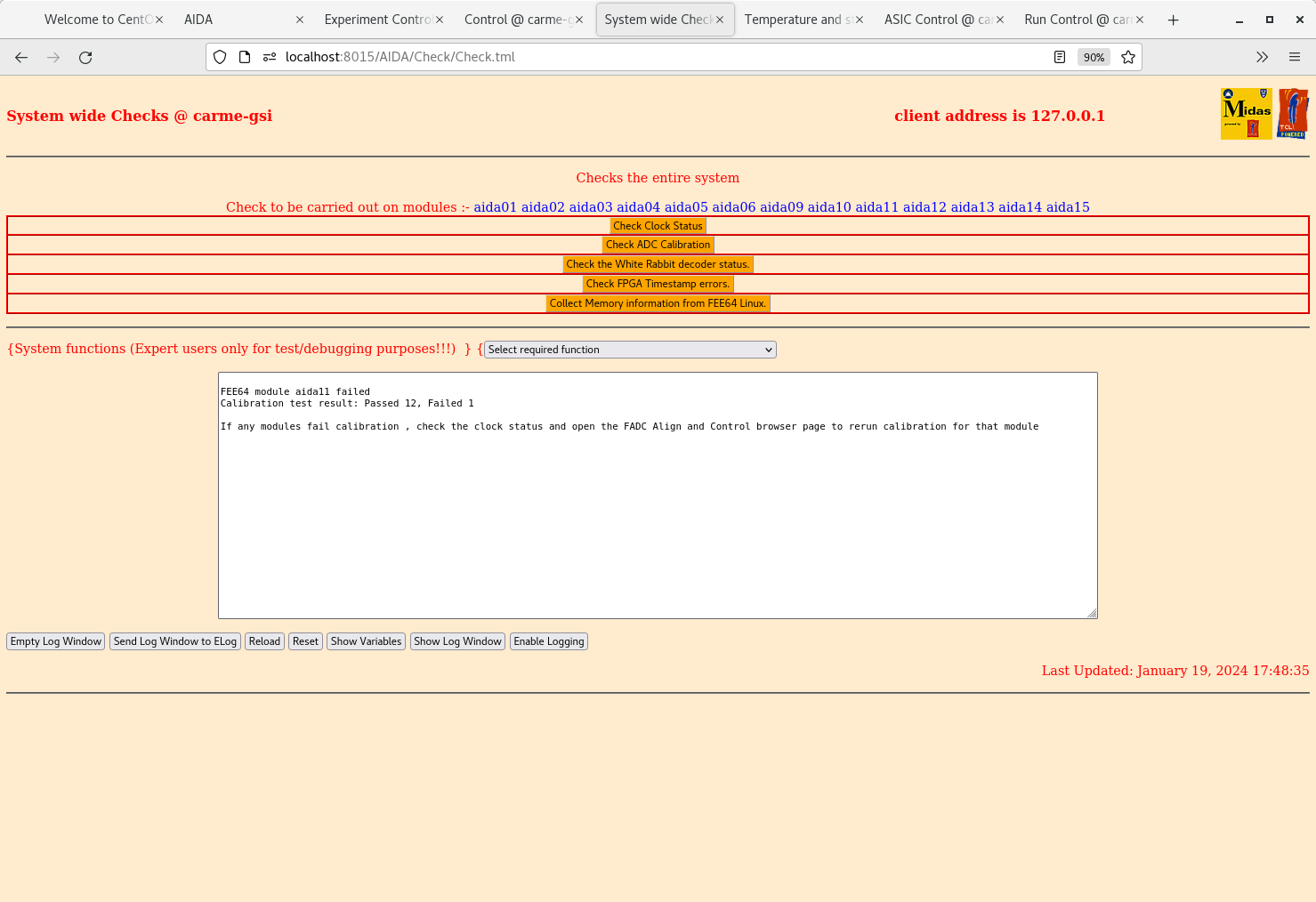
|
| Attachment 11: Screenshot_from_2024-01-19_17-48-46.png
|

|
| Attachment 12: Screenshot_from_2024-01-19_17-48-51.png
|

|
| Attachment 13: Screenshot_from_2024-01-19_17-49-11.png
|

|
| Attachment 14: Screenshot_from_2024-01-19_17-49-23.png
|

|
| Attachment 15: Screenshot_from_2024-01-19_17-43-55.png
|

|
| Attachment 16: Screenshot_from_2024-01-19_17-54-33.png
|
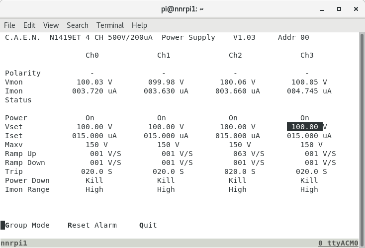
|
| Attachment 17: Screenshot_from_2024-01-19_17-56-01.png
|

|
| Attachment 18: Screenshot_from_2024-01-19_18-41-45.png
|

|
|
475
|
Thu Jan 18 17:21:00 2024 |
TD | Thursday 18 January |
Network ( dhcpd.conf ) and MIDAS startup.tcl/Options/ASIC settings/rfs filesystems configured


17.20 CARME IE514 4.1e-11mbar, ambient temperature 16.7 deg C
Pressure appears to be drifting upwards - see attachment 1 |
| Attachment 1: Capture.PNG
|

|
|
474
|
Wed Jan 17 19:21:20 2024 |
TD | AIDA spares |
Spare AIDA hardware

1x AIDA FEE64 PSU
1x USB-controlled ac mains relay

Transferred from EX 2.039 store ( ESR roof ) to CARME storage bins adjacent to CRYRING counting room ( CRYRING roof ).

CRYRING Hall

12 USB-Jtag cables ( sys console ) + 1x to Edinburgh Jan 2024 to fabricate more with spare Jtag PCBs
7x HDMI FEE64 - MACB cables
0x 0.3m HDMI-HDMI cables - require 8x 0.3m HDMI - HDMI cables + 2x 3m HDMI-HDMI cables
2x MACB
1x NIM WR emulator
1x Dlink 7 port USB extender
1x Netgear 24-port Gbit network switch
1x CAEN N1419ET ( ch #0 u/s ? )
0x 10m RJ45 Cat 6 network cables yellow/green/purple/brown - require 2x of each |
|
473
|
Wed Jan 17 19:15:47 2024 |
TD | Wednesday 17 January |
CAEN N1419ET remote control via carme-gsi and nnrpi1 - see https://elog.ph.ed.ac.uk/CARME/472

15x ( of 16x ) AIDA power cables available, labelled #1 - #15, installed

16x ( of 16x ) RJ45 Cat 6 network cables available, 15x labelled #1 - #15

16x ( of 16x ) HDMI cables available, labelled #1 - #16 |
|
472
|
Wed Jan 17 10:31:05 2024 |
TD | Remote control of CAEN N1419ET from nnrpi1 |
Login to nnrpi1 from carme-gsi using ssh

Execute the caen_screen.sh script

pi@nnrpi1:~ $ cat ./caen_screen.sh
if ! screen -list | grep -q "caenhv"; then
	screen -f -S caenhv /dev/ttyACM0 9600
else
	screen -x caenhv
fi
pi@nnrpi1:~ $ ./caen_screen.sh

Enter the text string 'caen'

If the CAEN display program is already running you will only see page updates/changes.
- enter q ( quit ) and then d ( display ) to re-display the entire screen.

See attachment 1 |
| Attachment 1: Capture.PNG
|
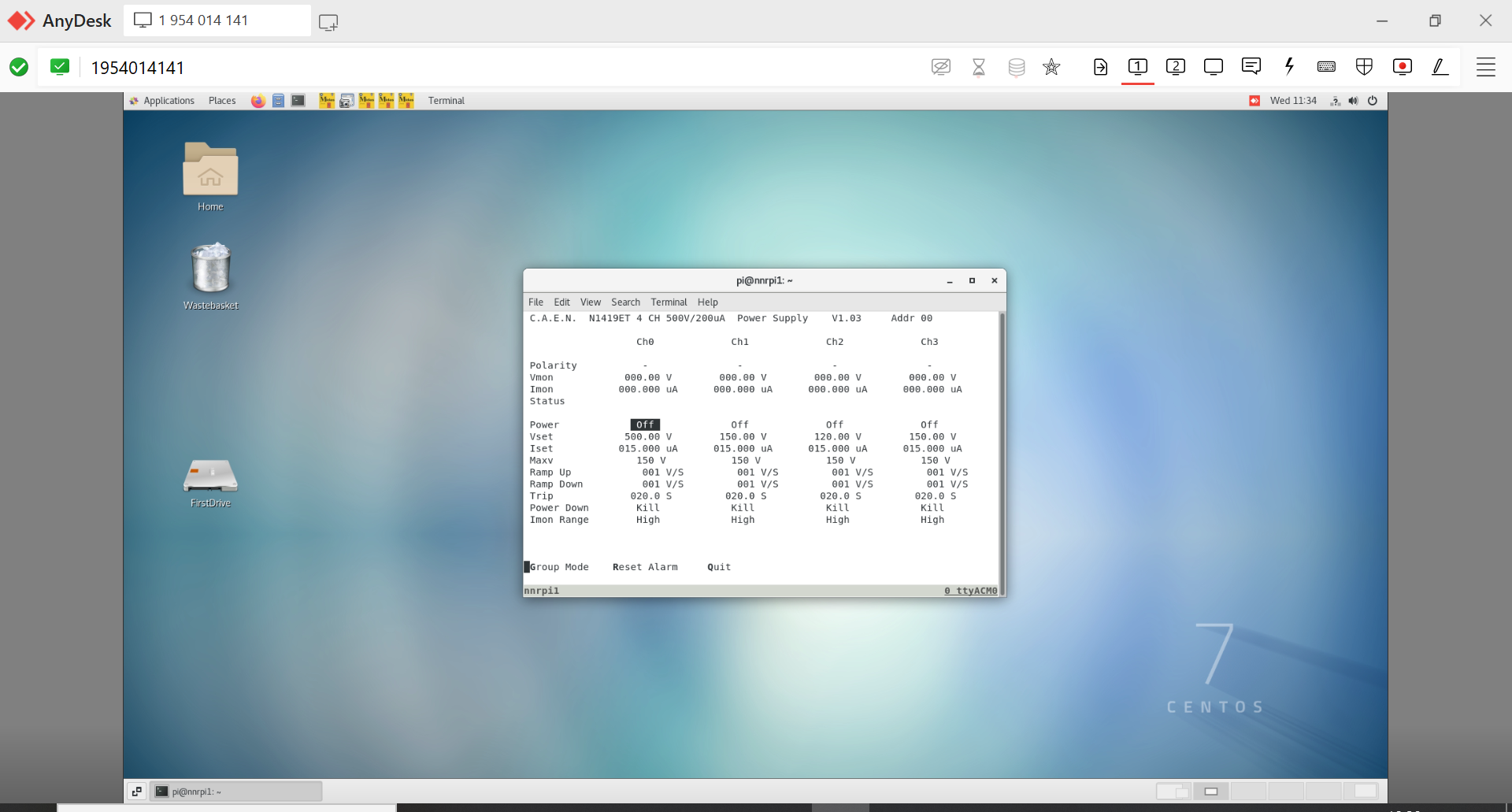
|
|
471
|
Tue Jan 16 16:01:48 2024 |
TD | Change CARMEraspberrypi to nnrpi1 |
Change RPi from CARMEraspberrypi to nnrpi1 to provide carme-gsi access to Rly16 to control USB-controlled ac mains relay.
nnrpi1 is already defined in carme-gsi:/etc/dhcp/dhcpd.conf

Transfer RPi network connection from CRYRING local network to AIDA 24-port network Gbit switch

Change /etc/hostname from

CARMEraspberrypi

to

nnrpi1

Change /etc/hosts from

127.0.0.1	localhost
::1		localhost ip6-localhost ip6-loopback
ff02::1		ip6-allnodes
ff02::2		ip6-allrouters

127.0.1.1	raspberrypi

to

127.0.0.1	localhost
::1		localhost ip6-localhost ip6-loopback
ff02::1		ip6-allnodes
ff02::2		ip6-allrouters

127.0.1.1	nnrpi1

Reboot RPi

Login to RPi and start MIDAS 8015 service

/MIDAS/TclHttpd/linux-arm/TclHttpd-server &

Open new browser tab on carme-gsi

http://nnrpi1:8015/AIDA/Rly16/Rly16.tml |
| Attachment 1: Capture.PNG
|

|
|
470
|
Tue Jan 16 14:36:30 2024 |
TD | CARME configuration |
FEE64

#1 - #16 -> aida01 - aida16

Network configuration - /etc/dhcpd/dhcpd.conf - attachment 1

MIDAS Options

Added Options sub-directories for aida09-aida16 - attachment 2

MIDAS ASIC settings

Added sub-directories for aida09-aida16 - attachment 3

MIDAS configuration - /MIDAS/config/TclHttpd/carme-gsi"8015 - attachment 4
Currently only aida01-aida08 defined

MIDAS embedded rfs filesystems for aida01-aida24 alreday exist - attachment 5

All FEE64s connected to rev B CARME adaptor PCBs
LK1 fitted to n+n bias FEE64 ( aidaxx, aidaxx, aidaxx, aidaxx )
No other LKs fitted


MACB

WR source NIM WR emulator or VETAR2

See https://elog.ph.ed.ac.uk/DESPEC/517 for MACB mode configuration


CAEN N1419ET


EG&G Ortec 448 Pulser


ASIC settings


Options |
| Attachment 1: dhcpd.conf
|
#
# DHCP Server Configuration file.
#   see /usr/share/doc/dhcp*/dhcpd.conf.example
#   see dhcpd.conf(5) man page
#
# 2 days
#default-lease-time 172800;
# 4 days
default-lease-time 345600;
# 8 days
max-lease-time 691200;

option domain-search code 119 = string;

option domain-name "dl.ac.uk";
option domain-name-servers 193.62.115.16, 148.79.80.78;
option netbios-name-servers 148.79.160.89;
option netbios-node-type 8;
option nis-domain "nuclear.physics";
option nis-servers 193.62.115.77;


subnet 192.168.11.0 netmask 255.255.255.0 {
   option subnet-mask 255.255.255.0;
   option broadcast-address 192.168.11.255;
   pool {
 range 192.168.11.118 192.168.11.199;
   }
}

group {
   use-host-decl-names true;
   default-lease-time 3600;
   max-lease-time 14400;

   server-name "192.168.11.99";
   next-server 192.168.11.99;

   host nnrpi1 {
     hardware ethernet dc:a6:32:1d:21:db;
     fixed-address 192.168.11.251;
   }

   host nnrpi2 {
     hardware ethernet b8:27:eb:40:53:e8;
     fixed-address 192.168.11.117;
   }

   host aida01 {
     hardware ethernet d8:80:39:41:d8:20;
     fixed-address 192.168.11.1;
    option root-path "/home/Embedded/XilinxLinux/ppc_4xx/rfs/aida01";
   }

   host aida02 {
     hardware ethernet d8:80:39:41:d8:2a;
     fixed-address 192.168.12.2;
    option root-path "/home/Embedded/XilinxLinux/ppc_4xx/rfs/aida02";
   }

   host aida03 {
     hardware ethernet d8:80:39:41:d0:05;
     fixed-address 192.168.11.3;
    option root-path "/home/Embedded/XilinxLinux/ppc_4xx/rfs/aida03";
   }

   host aida04 {
     hardware ethernet d8:80:39:41:b4:0b;
     fixed-address 192.168.11.4;
    option root-path "/home/Embedded/XilinxLinux/ppc_4xx/rfs/aida04";
   }

   host aida05 {
     hardware ethernet d8:80:39:42:0d:0c;
     fixed-address 192.168.11.5;
    option root-path "/home/Embedded/XilinxLinux/ppc_4xx/rfs/aida05";
   }

   host aida06 {
     hardware ethernet d8:80:39:41:d7:cd;
     fixed-address 192.168.11.6;
    option root-path "/home/Embedded/XilinxLinux/ppc_4xx/rfs/aida06";
   }

   host aida07 {
     hardware ethernet d8:80:39:41:d4:16;
     fixed-address 192.168.11.7;
    option root-path "/home/Embedded/XilinxLinux/ppc_4xx/rfs/aida07";
   }

   host aida08 {
     hardware ethernet d8:80:39:41:ba:2b;
     fixed-address 192.168.11.8;
    option root-path "/home/Embedded/XilinxLinux/ppc_4xx/rfs/aida08";
   }

   host aida09 {
     hardware ethernet d8:80:39:41:d0:0e;
     fixed-address 192.168.11.9;
    option root-path "/home/Embedded/XilinxLinux/ppc_4xx/rfs/aida09";
   }

   host aida10 {
     hardware ethernet d8:80:39:41:d8:2b;
     fixed-address 192.168.11.10;
    option root-path "/home/Embedded/XilinxLinux/ppc_4xx/rfs/aida10";
   }

   host aida11 {
     hardware ethernet d8:80:39:41:d7:cc;
     fixed-address 192.168.11.11;
    option root-path "/home/Embedded/XilinxLinux/ppc_4xx/rfs/aida11";
   }

   host aida12 {
     hardware ethernet d8:80:39:41:d7:c2;
     fixed-address 192.168.11.12;
    option root-path "/home/Embedded/XilinxLinux/ppc_4xx/rfs/aida12";
   }

   host aida13 {
     hardware ethernet d8:80:39:41:ba:22;
     fixed-address 192.168.11.13;
    option root-path "/home/Embedded/XilinxLinux/ppc_4xx/rfs/aida13";
   }

   host aida14 {
     hardware ethernet d8:80:39:41:ee:72;
     fixed-address 192.168.11.14;
    option root-path "/home/Embedded/XilinxLinux/ppc_4xx/rfs/aida14";
   }

   host aida15 {
     hardware ethernet d8:80:39:41:ee:71;
     fixed-address 192.168.11.15;
    option root-path "/home/Embedded/XilinxLinux/ppc_4xx/rfs/aida15";
   }

   host aida16 {
     hardware ethernet d8:80:39:41:a0:71;
     fixed-address 192.168.11.16;
    option root-path "/home/Embedded/XilinxLinux/ppc_4xx/rfs/aida16";
   }

}


subnet 192.168.12.0 netmask 255.255.255.0 {
   option subnet-mask 255.255.255.0;
   option broadcast-address 192.168.12.255;
   pool {
 range 192.168.12.100 192.168.12.199;
   }
}

group {
   use-host-decl-names true;
   default-lease-time 3600;
   max-lease-time 14400;

   server-name "192.168.12.99";
   next-server 192.168.12.99

}
|
| Attachment 2: Options
|
[npg@carme-gsi Options]$ pwd
/MIDAS/DB/EXPERIMENTS/AIDA/Options
[npg@carme-gsi Options]$ ls -lR
.:
total 0
drwxrwxr-x. 2 npg npg 22 Jan 31 2022 aida01
drwxrwxr-x. 2 npg npg 22 Jan 31 2022 aida02
drwxrwxr-x. 2 npg npg 22 Jan 31 2022 aida03
drwxrwxr-x. 2 npg npg 22 Jan 31 2022 aida04
drwxrwxr-x. 2 npg npg 22 Jan 31 2022 aida05
drwxrwxr-x. 2 npg npg 22 Jan 31 2022 aida06
drwxrwxr-x. 2 npg npg 22 Jan 31 2022 aida07
drwxrwxr-x. 2 npg npg 22 Jan 31 2022 aida08
drwxrwxr-x. 2 npg npg 22 Jan 18 15:15 aida09
drwxrwxr-x. 2 npg npg 22 Jan 18 15:15 aida10
drwxrwxr-x. 2 npg npg 22 Jan 18 15:15 aida11
drwxrwxr-x. 2 npg npg 22 Jan 18 15:15 aida12
drwxrwxr-x. 2 npg npg 22 Jan 18 15:15 aida13
drwxrwxr-x. 2 npg npg 22 Jan 18 15:15 aida14
drwxrwxr-x. 2 npg npg 22 Jan 18 15:15 aida15
drwxrwxr-x. 2 npg npg 22 Jan 18 15:15 aida16
./aida01:
total 4
-rwxrwxr-x. 1 npg npg 1027 Nov 28 2022 CONTENTS
./aida02:
total 4
-rwxrwxr-x. 1 npg npg 1026 Feb 19 2022 CONTENTS
./aida03:
total 4
-rwxrwxr-x. 1 npg npg 1026 Feb 13 2022 CONTENTS
./aida04:
total 4
-rwxrwxr-x. 1 npg npg 1026 Dec 1 2022 CONTENTS
./aida05:
total 4
-rwxrwxr-x. 1 npg npg 1027 Nov 30 2022 CONTENTS
./aida06:
total 4
-rwxrwxr-x. 1 npg npg 1026 Feb 4 2022 CONTENTS
./aida07:
total 4
-rwxrwxr-x. 1 npg npg 1026 Jan 31 2022 CONTENTS
./aida08:
total 4
-rwxrwxr-x. 1 npg npg 1026 Feb 4 2022 CONTENTS
./aida09:
total 4
-rwxrwxr-x. 1 npg npg 1026 Jan 18 15:15 CONTENTS
./aida10:
total 4
-rwxrwxr-x. 1 npg npg 1026 Jan 18 15:15 CONTENTS
./aida11:
total 4
-rwxrwxr-x. 1 npg npg 1026 Jan 18 15:15 CONTENTS
./aida12:
total 4
-rwxrwxr-x. 1 npg npg 1026 Jan 18 15:15 CONTENTS
./aida13:
total 4
-rwxrwxr-x. 1 npg npg 1026 Jan 18 15:15 CONTENTS
./aida14:
total 4
-rwxrwxr-x. 1 npg npg 1026 Jan 18 15:15 CONTENTS
./aida15:
total 4
-rwxrwxr-x. 1 npg npg 1026 Jan 18 15:15 CONTENTS
./aida16:
total 4
-rwxrwxr-x. 1 npg npg 1026 Jan 18 15:15 CONTENTS
[npg@carme-gsi Options]$ cat aida02/CONTENTS
Index string Stat.offset&&Aida_Hist_W_Enable&&TS_SYNC_PHASE&&ExtClk&&Aida.shift&&MACB_TRIG_MODE&&Aida.offset&&RunNumber&&Aida_GroupBase&&Rate.channels&&Stat.channels&&Aida.Vchannels&&ASIC.settings&&Aida_Hist_D_Enable&&WAVE_DMA_HWM&&Stat.shift&&Aida.Wchannels&&Aida_Hist_V_Enable&&Include.Aida&&Aida.channels&&DataAcqPgm&&Aida_Hist_H_Enable&&DataFormat&&ASIC_DMA_HWM&&Aida_Hist_L_Enable
Stat.offset string 64
Aida_Hist_W_Enable string 1
Aida.shift string 0
TS_SYNC_PHASE string 0x0
ExtClk string 1
Aida.offset string 0
MACB_TRIG_MODE string 4
RunNumber string 63
Rate.channels string 512
Aida_GroupBase string 1
Stat.channels string 512
Aida_Hist_D_Enable string 1
ASIC.settings string 2022Jan31-11-52-00
Aida.Vchannels string 256
WAVE_DMA_HWM string 0x0007ffff
Aida.Wchannels string 1020
Stat.shift string 6
Include.Aida string 0
Aida_Hist_V_Enable string 0
Aida.channels string 65536
DataFormat string 0x0000
DataAcqPgm string AidaExecV9
Aida_Hist_H_Enable string 1
ASIC_DMA_HWM string 0x000fffff
Aida_Hist_L_Enable string 1
|
| Attachment 3: Settings
|
[npg@carme-gsi 2022Jan31-11-52-00]$ pwd
/MIDAS/DB/EXPERIMENTS/AIDA/2022Jan31-11-52-00
[npg@carme-gsi 2022Jan31-11-52-00]$ ls -lR
.:
total 0
drwxrwxr-x. 2 npg npg 22 Jan 31  2022 aida01
drwxrwxr-x. 2 npg npg 22 Jan 31  2022 aida02
drwxrwxr-x. 2 npg npg 22 Jan 31  2022 aida03
drwxrwxr-x. 2 npg npg 22 Jan 31  2022 aida04
drwxrwxr-x. 2 npg npg 22 Jan 31  2022 aida05
drwxrwxr-x. 2 npg npg 22 Jan 31  2022 aida06
drwxrwxr-x. 2 npg npg 22 Jan 31  2022 aida07
drwxrwxr-x. 2 npg npg 22 Jan 31  2022 aida08
drwxrwxr-x. 2 npg npg 22 Jan 18 15:21 aida09
drwxrwxr-x. 2 npg npg 22 Jan 18 15:21 aida10
drwxrwxr-x. 2 npg npg 22 Jan 18 15:21 aida11
drwxrwxr-x. 2 npg npg 22 Jan 18 15:21 aida12
drwxrwxr-x. 2 npg npg 22 Jan 18 15:21 aida13
drwxrwxr-x. 2 npg npg 22 Jan 18 15:21 aida14
drwxrwxr-x. 2 npg npg 22 Jan 18 15:21 aida15
drwxrwxr-x. 2 npg npg 22 Jan 18 15:21 aida16

./aida01:
total 4
-rwxrwxr-x. 1 npg npg 2726 Jan 31  2022 CONTENTS

./aida02:
total 4
-rwxrwxr-x. 1 npg npg 2726 Jan 31  2022 CONTENTS

./aida03:
total 4
-rwxrwxr-x. 1 npg npg 2726 Jan 31  2022 CONTENTS

./aida04:
total 4
-rwxrwxr-x. 1 npg npg 2726 Jan 31  2022 CONTENTS

./aida05:
total 4
-rwxrwxr-x. 1 npg npg 2726 Jan 31  2022 CONTENTS

./aida06:
total 4
-rwxrwxr-x. 1 npg npg 2726 Jan 31  2022 CONTENTS

./aida07:
total 4
-rwxrwxr-x. 1 npg npg 2726 Jan 31  2022 CONTENTS

./aida08:
total 4
-rwxrwxr-x. 1 npg npg 2726 Jan 31  2022 CONTENTS

./aida09:
total 4
-rwxrwxr-x. 1 npg npg 2726 Jan 18 15:21 CONTENTS

./aida10:
total 4
-rwxrwxr-x. 1 npg npg 2726 Jan 18 15:21 CONTENTS

./aida11:
total 4
-rwxrwxr-x. 1 npg npg 2726 Jan 18 15:21 CONTENTS

./aida12:
total 4
-rwxrwxr-x. 1 npg npg 2726 Jan 18 15:21 CONTENTS

./aida13:
total 4
-rwxrwxr-x. 1 npg npg 2726 Jan 18 15:21 CONTENTS

./aida14:
total 4
-rwxrwxr-x. 1 npg npg 2726 Jan 18 15:21 CONTENTS

./aida15:
total 4
-rwxrwxr-x. 1 npg npg 2726 Jan 18 15:21 CONTENTS

./aida16:
total 4
-rwxrwxr-x. 1 npg npg 2726 Jan 18 15:21 CONTENTS

[npg@carme-gsi 2022Jan31-11-52-00]$ cat aida02/CONTENTS
ASIC.1.3 string 0x02
ASIC.2.19 string 0x5c
ASIC.2.20 string 0x68
ASIC.1.4 string 0x07
ASIC.2.21 string 0x0f
ASIC.2.22 string 0x5c
ASIC.1.5 string 0x08
ASIC.1.6 string 0x09
ASIC.2.23 string 0x08
ASIC.2.24 string 0x68
ASIC.1.7 string 0x05
ASIC.2.25 string 0x08
ASIC.1.8 string 0x00
ASIC.2.26 string 0xbf
ASIC.1.9 string 0x0f
ASIC.2.0 string 0x04
ASIC.2.1 string 0x05
ASIC.3.10 string 0x00
ASIC.2.2 string 0x06
ASIC.3.11 string 0x0d
ASIC.2.3 string 0x02
ASIC.3.12 string 0x64
ASIC.2.4 string 0x07
ASIC.3.13 string 0x34
ASIC.2.5 string 0x08
ASIC.3.14 string 0x02
ASIC.2.6 string 0x09
ASIC.3.15 string 0xff
ASIC.2.7 string 0x05
ASIC.3.16 string 0xd2
ASIC.2.8 string 0x00
ASIC.3.17 string 0x80
ASIC.2.9 string 0x0f
ASIC.3.18 string 0xb2
WAVE.0 string 0x00000000
ASIC.3.20 string 0x68
ASIC.3.19 string 0x5c
WAVE.1 string 0x00000000
ASIC.3.21 string 0x0f
WAVE.2 string 0x00000000
LED.0 string 0x00011d4c
ASIC.3.22 string 0x5c
WAVE.3 string 0x00000000
LED.1 string 0x0000ffff
ASIC.3.23 string 0x08
LED.2 string 0x00011b58
ASIC.3.24 string 0x68
ASIC.1.10 string 0x00
LED.3 string 0x00000000
ASIC.3.25 string 0x08
ASIC.3.0 string 0x04
ASIC.3.26 string 0xbf
ASIC.1.11 string 0x0d
LED.4 string 0x00011b58
LED.5 string 0x00000000
ASIC.3.1 string 0x05
ASIC.1.12 string 0x64
ASIC.1.13 string 0x34
ASIC.3.2 string 0x06
LED.6 string 0x00011b58
LED.7 string 0x00000000
ASIC.1.14 string 0x02
ASIC.3.3 string 0x02
ASIC.1.15 string 0xff
ASIC.3.4 string 0x07
LED.8 string 0x000003fc
LED.9 string 0x000000c8
ASIC.1.16 string 0xd2
ASIC.3.5 string 0x08
ASIC.1.17 string 0x80
ASIC.3.6 string 0x09
ASIC.1.18 string 0xb2
ASIC.3.7 string 0x05
ASIC.1.20 string 0x68
ASIC.3.8 string 0x00
ASIC.1.19 string 0x5c
ASIC.3.9 string 0x0f
ASIC.1.21 string 0x0f
ASIC.4.10 string 0x00
ASIC.1.22 string 0x5c
ASIC.1.23 string 0x08
ASIC.4.11 string 0x0d
ASIC.4.12 string 0x64
ASIC.1.24 string 0x68
ASIC.1.25 string 0x08
ASIC.4.13 string 0x34
ASIC.4.14 string 0x02
ASIC.1.26 string 0xbf
ASIC.4.15 string 0xff
ASIC.4.16 string 0xd2
DISC.6 string 0x00000002
DISC.7 string 0x24800000
ASIC.4.0 string 0x04
ASIC.4.17 string 0x80
ASIC.4.18 string 0xb2
ASIC.4.1 string 0x05
ASIC.4.20 string 0x68
ASIC.4.2 string 0x06
ASIC.4.19 string 0x5c
ASIC.4.3 string 0x02
ASIC.4.21 string 0x0f
ASIC.4.22 string 0x5c
ASIC.4.4 string 0x07
ASIC.4.5 string 0x08
ASIC.4.23 string 0x08
ASIC.4.24 string 0x68
ASIC.4.6 string 0x09
ASIC.2.10 string 0x00
ASIC.4.7 string 0x05
ASIC.4.25 string 0x08
ASIC.4.26 string 0xbf
ASIC.4.8 string 0x00
ASIC.2.11 string 0x0d
ASIC.2.12 string 0x64
ASIC.4.9 string 0x0f
ASIC.2.13 string 0x34
ASIC.2.14 string 0x02
ASIC.2.15 string 0xff
ASIC.2.16 string 0xd2
ASIC.1.0 string 0x04
ASIC.1.1 string 0x05
ASIC.2.17 string 0x80
ASIC.2.18 string 0xb2
ASIC.1.2 string 0x06
|
| Attachment 4: startup.tcl
|
   Setting BGColor "BlanchedAlmond"
   Setting TextColor "red"

      Setting ProjectName  AIDA
      Setting ProjectImage AIDA.gif
      Setting ProjectURL   "http://npg.dl.ac.uk/NPG/Projects/Fair.html"


  Setting Option1Name STFC
  Setting Option1URL  "stfc.ac.uk"
  Setting Option1Image stfc.jpg


# global MessageLoggerServerHost
#  set  MessageLoggerServerHost nndhcp077.dl.ac.uk

#    package require  MessageLoggerClient

#  Setting Option3Name "Elog Server"
#  Setting Option3URL  "http://nndhcp077.dl.ac.uk:8080/DataAcq/"

#    Install required services

    if {![namespace exists ::AIDA]} {namespace eval ::AIDA {puts "created namespace ::AIDA"}}
#    set ::AIDA::TestMode 1

    global SpectrumServerHost
    set SpectrumServerHost aidas

   package require XAIDAAccessClient  ;# for Client end - ie AIDA server workstation  sets MIDAS_XAIDAAccessClient_Exists (SOAP)

   package require XAD9252AccessClient ;# for Client end - ie AIDA server workstation  sets MIDAS_XAD9252AccessClient_Exists (SOAP)

namespace eval DataAcquisition {
     variable PROJECT AIDA
     variable ACQSERVERS
     set ACQSERVERS [list aida01 aida02 aida03 aida04 aida05 aida06 aida07 aida08]
     variable ACQSERVER [first $ACQSERVERS]
    variable DataTransferStreams; set DataTransferStreams 2
#     set ::DataAcquisition::EnableMerger 1
#     set ::DataAcquisition::EnableTape 1
    variable RDOGo 0
}

namespace eval AIDA {
      variable ModuleMenu; set ModuleMenu $::DataAcquisition::ACQSERVERS
      variable TSMaster; set TSMaster aida01
      variable FEE64 [first $ModuleMenu]
      variable ConfigBase; set ConfigBase [file join $env(MIDASBASE) config TclHttpd]
}

    Setting DataBaseRoot "/MIDAS/DB"
    package require DataBaseAccessServer

    package require NetVarsServer 1.1
    package require SigTaskServer

#    package require MemSasServer

#    Install services for Run Control

namespace eval $::DataAcquisition::PROJECT {
    variable DBRootName [file join EXPERIMENTS AIDA]
    variable DBNodeBase 2012
}

  package require AIDARunControl
#  package require TapeServer
#  package require MergerControl
#  package require MERGERunControl


  Setting Option7Name "Project Home Page"
  Setting Option7URL  "http://npg.dl.ac.uk/NPG/Projects/Fair.html"

  Setting Option8Name "Server Software Home Page"
  Setting Option8URL  "http://npg.dl.ac.uk/MIDAS/download/WebServices.html"
|
| Attachment 5: rfs
|
[npg@carme-gsi rfs]$ pwd
/MIDAS/Embedded/XilinxLinux/ppc_4xx/rfs
[npg@carme-gsi rfs]$ ls -l
total 1491780
drwxrwxrwx. 19 10101  500        227 Dec  1  2022 aida01
drwxrwxrwx. 19 10101  500        227 Dec  1  2022 aida02
drwxrwxrwx. 19 10101  500        227 Dec  1  2022 aida03
drwxrwxrwx. 19 10101  500        227 Dec  1  2022 aida04
drwxrwxrwx. 19 10101  500        227 Dec  1  2022 aida05
drwxrwxrwx. 19 10101  500        227 Feb 10  2022 aida06
drwxrwxrwx. 19 10101  500        227 Feb 10  2022 aida07
drwxrwxrwx. 19 10101  500        227 Feb 10  2022 aida08
drwxrwxrwx. 19 10101  500        227 Oct 29  2021 aida09
drwxrwxrwx. 19 10101  500        227 Oct 29  2021 aida10
drwxrwxrwx. 19 10101  500        227 Oct 29  2021 aida11
drwxrwxrwx. 19 10101  500        227 Oct 29  2021 aida12
drwxrwxrwx. 19 10101  500        227 Oct 29  2021 aida13
drwxrwxrwx. 19 10101  500        227 Oct 29  2021 aida14
drwxrwxrwx. 19 10101  500        227 Oct 29  2021 aida15
drwxrwxrwx. 19 10101  500        227 Oct 29  2021 aida16
drwxrwxrwx. 19 10101  500        227 Apr 28  2021 aida17
drwxrwxrwx. 19 10101  500        227 Apr 28  2021 aida18
drwxrwxrwx. 19 10101  500        227 Apr 28  2021 aida19
drwxrwxrwx. 19 10101  500        227 Apr 28  2021 aida20
drwxrwxrwx. 19 10101  500        227 Apr 28  2021 aida21
drwxrwxrwx. 19 10101  500        227 Apr 28  2021 aida22
drwxrwxrwx. 19 10101  500        227 Apr 28  2021 aida23
drwxrwxrwx. 19 10101  500        227 Apr 28  2021 aida24
-rw-r--r--.  1 root  root 1527582720 Apr 28  2021 rfs.tar
|
|
469
|
Tue Jan 16 08:57:44 2024 |
JG, DR, TD | Tuesday 16 January |
10.00 Outflow manifold returned from workshop with leaking attachment point welding re-worked.

11.30 Outflow hoses re-attached to outflow manifold. Faulty male Swagelok replaced.
      Outflow manifold tested on floor - no leaks observed.

      Mounted outflow manifold. All inflow/outflow hoses attached to FEE64s - see attachments 1-4.
      FEE64 #11 detached adaptor PCB - temporarily secured by cable tie.

      Inflow/outflow valves opened. Pin hole leak observed at 3/8" connector gasket - indicated by arrow attachment
3.
      Leak fixed by tightening fitting.

      1x spare inflow/outflow connected together - attachment 4.

11.40 CARME IE514 3.8e-11mbar, ambient temperature 16.5 deg C

15.05 8x AIDA FEE64 power cables ( #1 - #8 ) installed FEE64s #1 - #8
      Note - Samtec lock clips broken on 3 of 8 cables due to careless handling/poor storage
      AIDA FEE64 power cables tied to one of the FEE64 copper coolant pipes.

      See attachments 5-7

15.30 USB-controlled ac mains relay - USB connected to RPi CARMEbakingpi currently used for CAEN N1419ET
      Rear panel key switched to override - no flow/d.p. sensors currently installed - front panel water ( yellow ) and override ( red ) LEDs active.

16.15 Transfer CARMEbakingpi from CRYRING network to AIDA 24-port Gbit network switch connected to carme-gsi
      CARMEbakingpi becomes nnrpi1 p- can connect OK via ssh from carme-gsi

      Start server ( port 8015 ) manually

      ssh pi@nnrpi1

      /MIDAS/Tcl/Httpd/linux-arm/Tcl-Httpd-server &

See attachment 8 |
| Attachment 1: 1000009654.jpg
|

|
| Attachment 2: 1000009651.jpg
|

|
| Attachment 3: 1000009653.jpg
|

|
| Attachment 4: 1000009652.jpg
|

|
| Attachment 5: 1000009663.jpg
|
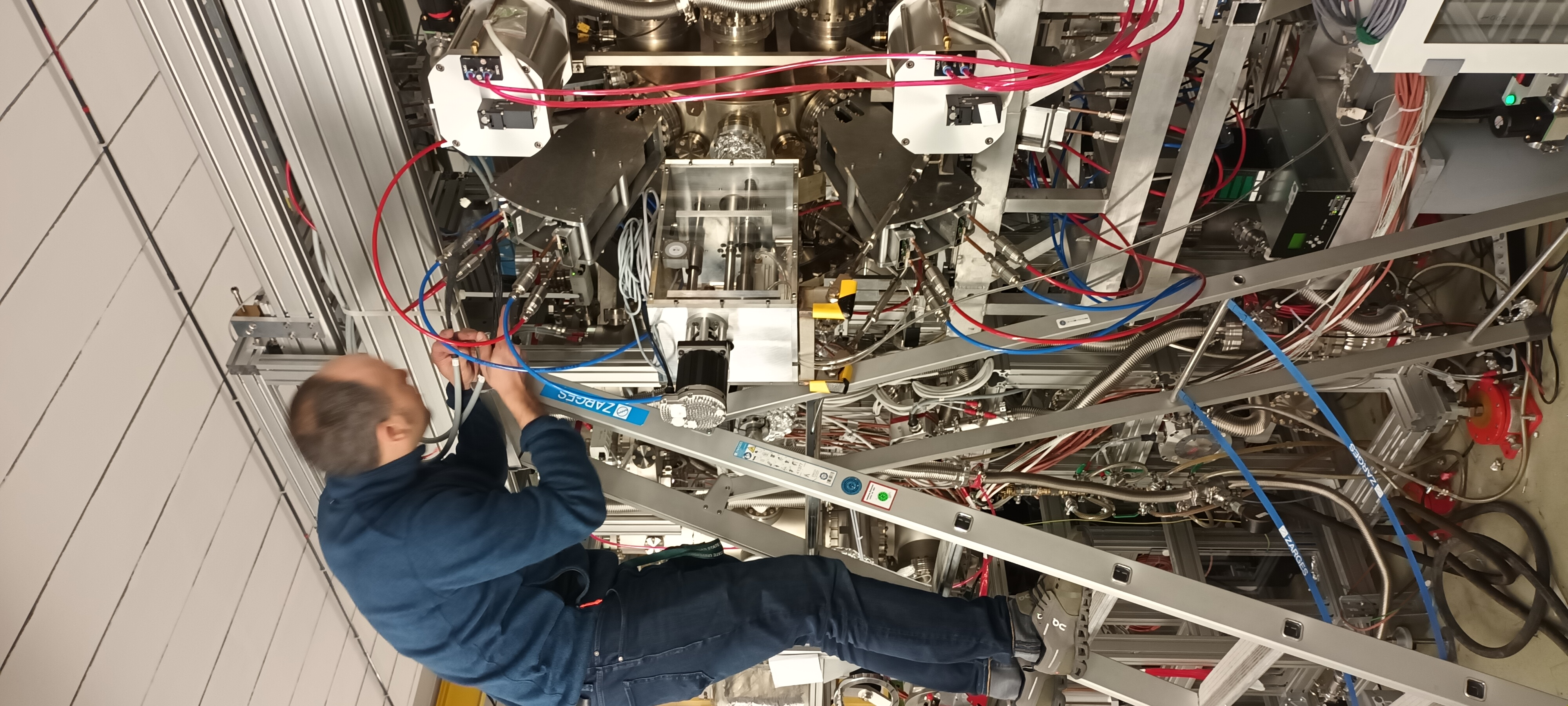
|
| Attachment 6: 1000009662.jpg
|
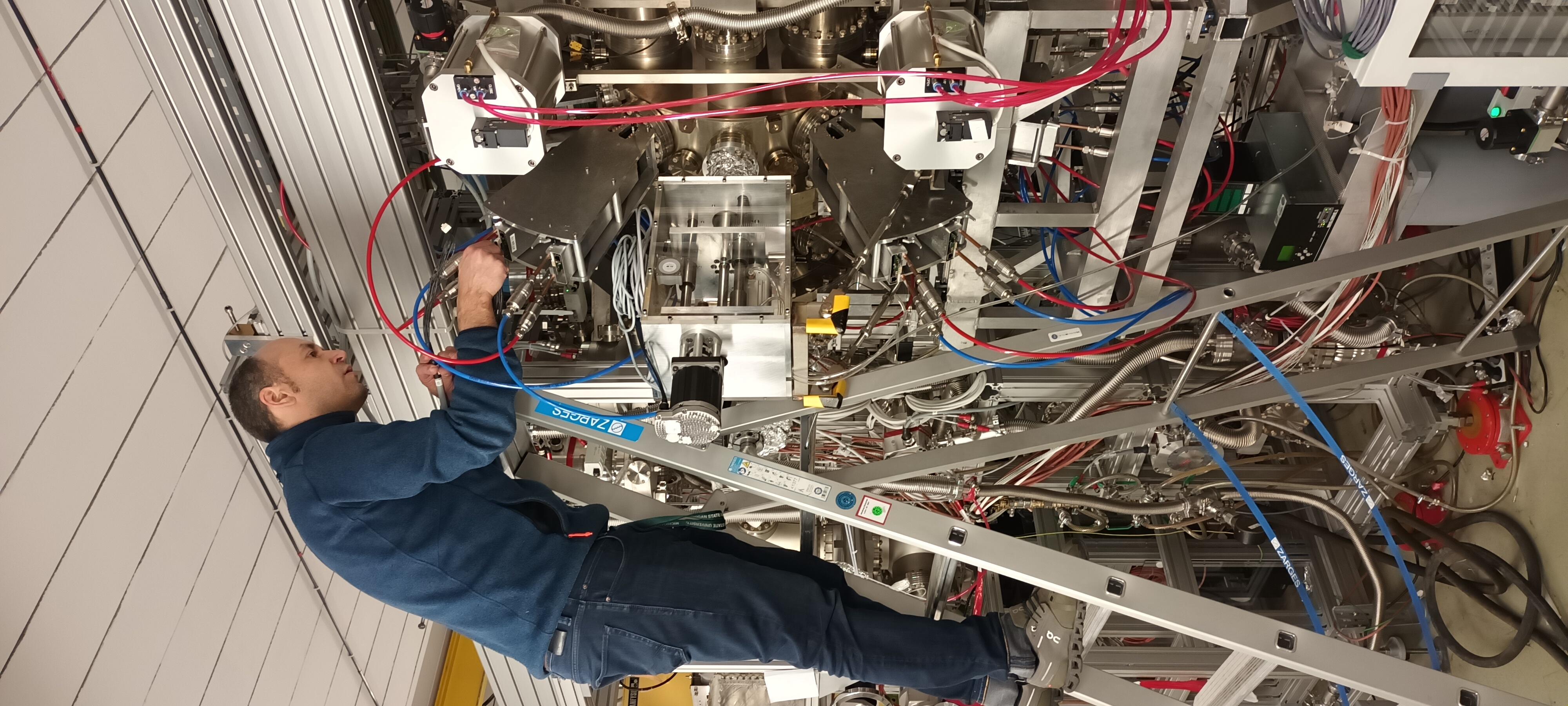
|
| Attachment 7: 1000009664.jpg
|
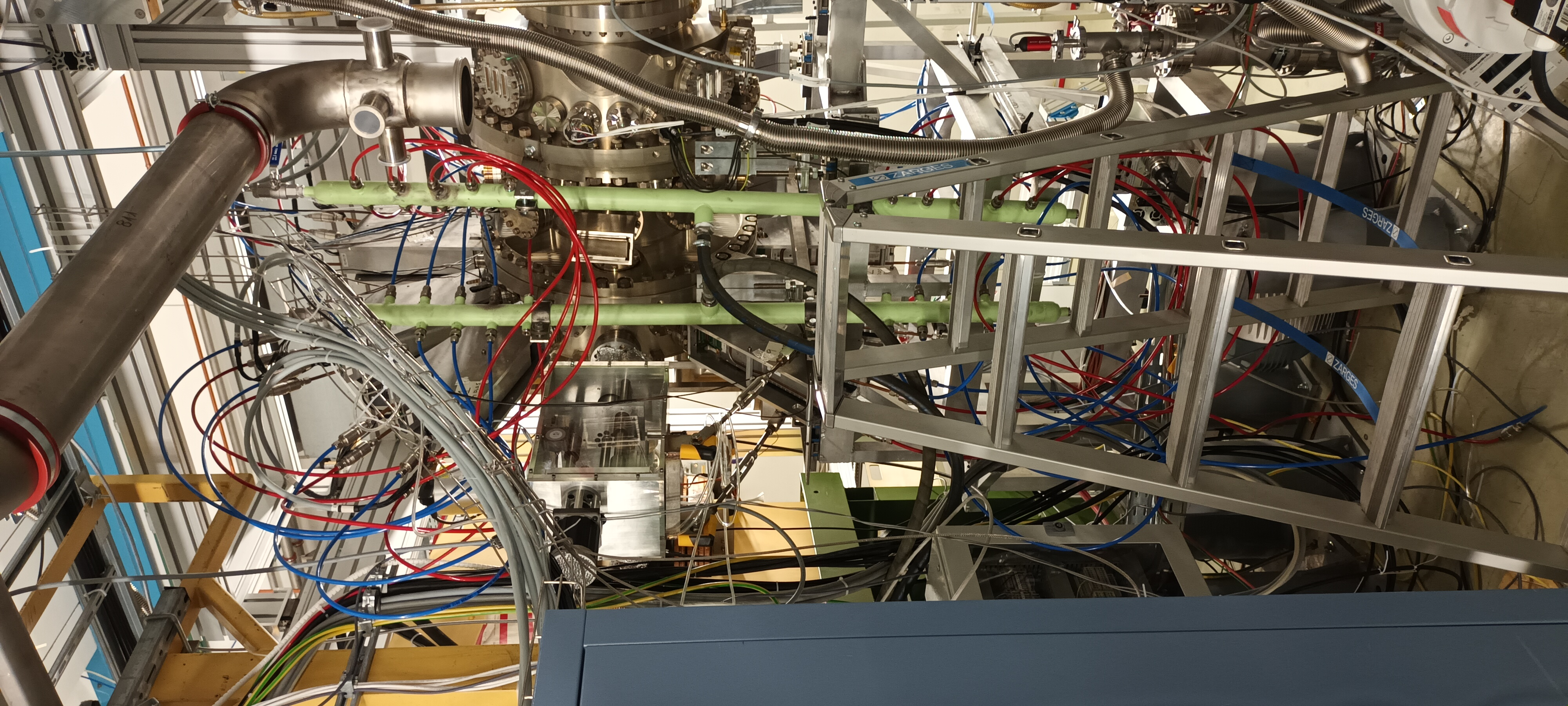
|
| Attachment 8: Capture.PNG
|

|
|
468
|
Mon Jan 15 18:51:28 2024 |
JG, DR, TD | Monday 15 January |
Cooling water manifolds


The manifolds were returned this afternoon.

Inflow manifold - blue hose, female Swagelok connectors

Attached to inflow hose and bled using bleed/drain valve.
Small leak observed at the 3/8" connection between the manifold and the bleed/drain valve - attachment tightened and leak fixed.
Inflow manifold installed.

Outflow manifold - red hose, male Swagelok connectors

Attached to outflow hose and bled using bleed/drain valve.
Small leak observed at the weld immediately *below* the weld that had been re-worked - this weld had not been re-worked.
Significant leak observed at one of the male Swagelok connectors in the lower half of the manifold - it does not seal correctly.


DR will return this manifold to the workshop for welding re-work Tuesday am.
The faulty male Swagelok will be replaced.


AIDA cabling


16x AIDA PSU, HDMI and RJ45 Cat 6 cables and 4x SHV-BNC cables required.

Available

8x AIDA PSU cables
1x AIDA PSU cable ( in one of two white plastic storage boxs with 7x FEE64s returned from STFC DL ) now appears to be missing

16x AIDA HDMI cables

8x RJ45 Cat 6 network cables
1x RJ45 Cat 6 network cable ( network switch to CRYRING network patch panel - to be replaced )
3x RJ45 Cat 6 network cables found in AIDA plastic box ( S4 Messehutte )

3x SHV-BNC

Will check DESPEC store above ESR with NH tomorrow afternoon. |
|
467
|
Sun Jan 14 12:31:32 2024 |
JM, CB | FEE positions mac addresses |
*Updated following FEE changes. Correct as of 31/01/24
FEE modules are labelled according to the diagram in attachment. Note attachment is looking downstream. Each FEE module is also labelled with its assigned number and whether it is a bias connection on the FEE holders. MAC addresses and FEE descriptions are as follows;
1 - 41:d8:20 - top left detector - pn bias
2 - 41:d8:2a - top left detector -
3 - 41:d0:05 - top left detector -
4 - 41:b4:0b - top left detector - nn bias
5 - 42:0d:0c - top right detector - pn bias
6 - 41:0d:16 - top rightdetector -
7 - 41:b4:16 - top right detector -
8 - 41:ba:2b - top right detector - nn bias
9 - 41:d0:0e - bottom left detector - nn bias
10 - 41:d8:2b - bottom left detector -
11 - 41:d7:cc - bottom left detector -
12 - 41:d7:c2 - bottom left detector - pn bias
13 - 41:ba:22 - bottom right detector - nn bias
14 - 41:ee:72 - bottom right detector -
15 - 41:a0:71 - bottom right detector -
16 - 41:ee:71 - bottom right detector - pn bias |
| Attachment 1: CARME-FEEs.jpg
|
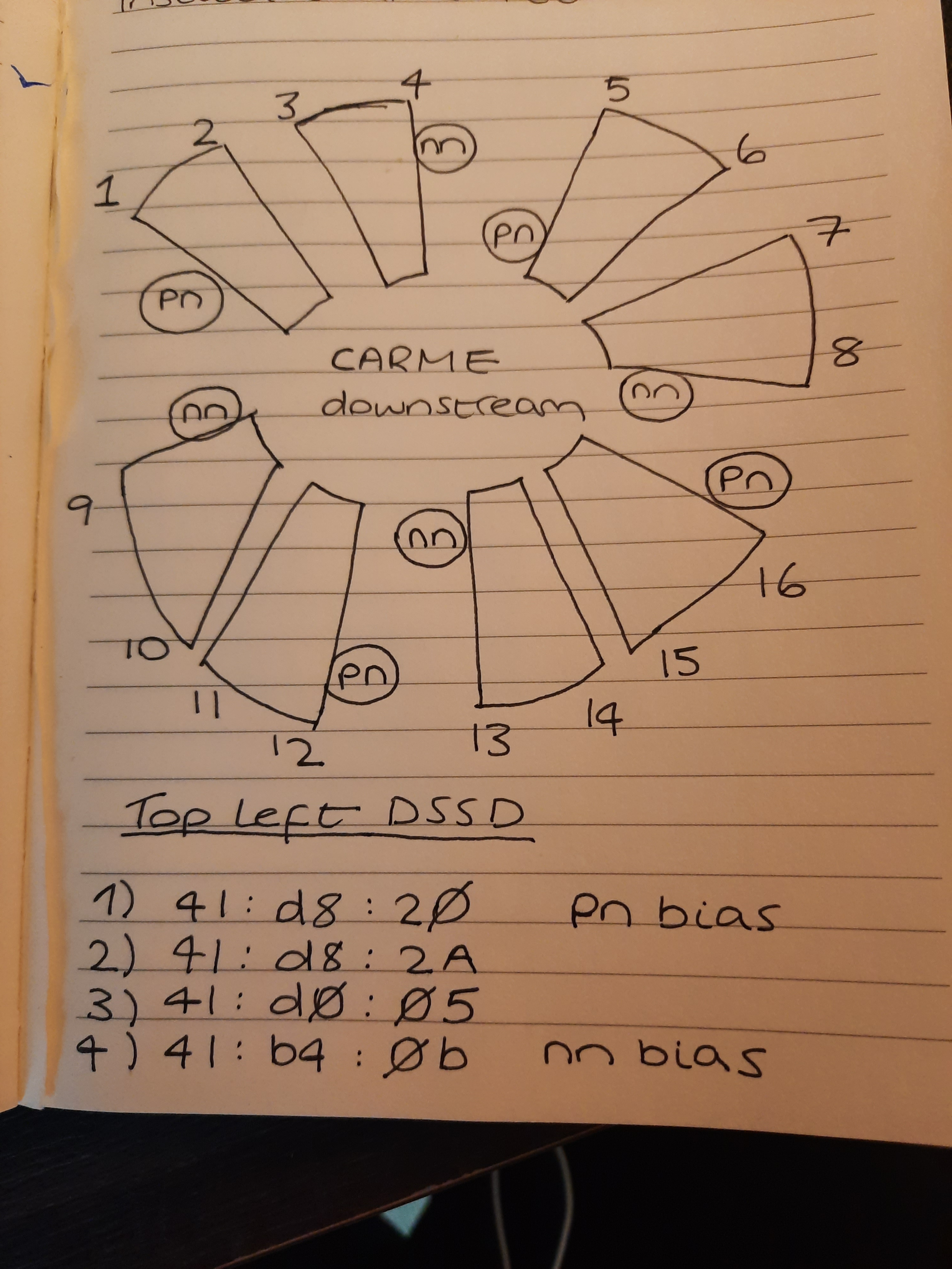
|
|
466
|
Sat Jan 13 14:32:21 2024 |
CB, JM | Leaky manifold and cable management |
Found two leaks in the welding of the manifolds, marked them in tape. Manifold to be repaired on Monday. Remember to re-install missing hoses, which are in a bucket in the cave.
See attached how it is supposed to look like.
Left hand hose (inlet) was too short and was cut to dismount the manifold. Davide will obtain a new tube of the same type and mount it for us. NOTE THAT THE INLET connector (BLUE manifold) was leaking. Unclear if this was the hose or poor plumbing.
Installed cable management system that was never used during the last beamtime. Started to thread cables through it. There should be sufficient space to re-install the manifolds with the cable tray in place. If this is difficult, the tray is installed with zip ties only so altering position should be relativly straightforward. The mounting points of the outlet manifold on the CARME chamber can also be rotated around to give a bit more space.
Cleaned up some boxes and moved heaters and some empty boxes to the CRYRING roof. |
| Attachment 1: 20240112_111838.jpg
|

|
| Attachment 2: 20240112_105936.jpg
|

|
| Attachment 3: 20240113_183019.jpg
|
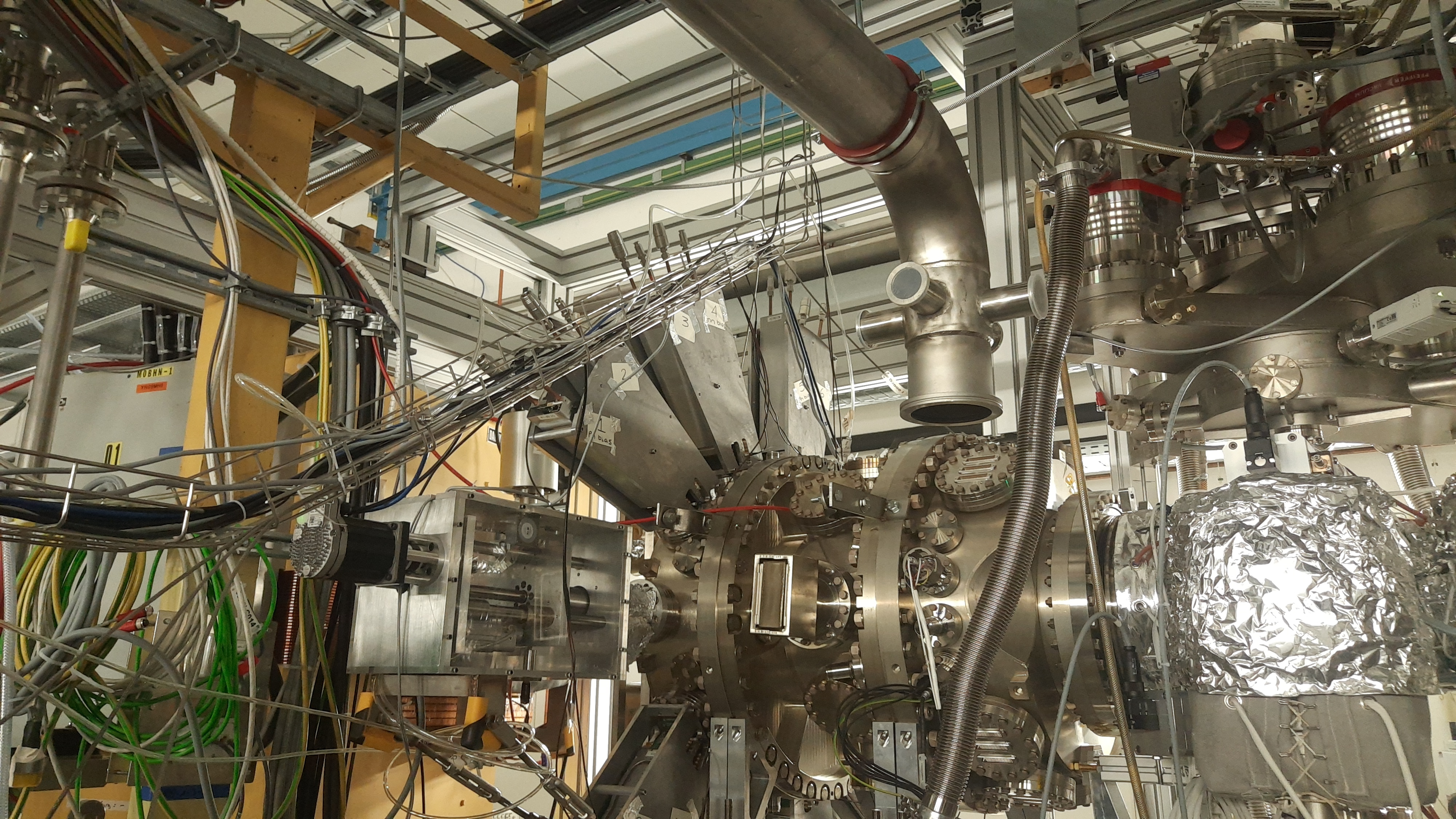
|
|
465
|
Sat Jan 13 14:25:05 2024 |
CB, JM | Bias tests with all FEEs connected |
Connected all FEEs.
The two top fees corresponding to the bottom right detector are connected to damaged flexi rigid PCBs. The top one is missing an pin that should not be connected to anything, while the bottom one has a slightly cracked connector and is missing the top left pin. Spares should be in Edinburgh.
Found that the flexi rigid PCB connected to the bottom most FEE of the bottom-left detector has a damaged ground lemo connector. Possibly pulled during mounting? The bias cables were off most of the time. Seems to bias fine using the other bias lemo, but not ideal.
Attached, a V-I plot of the four detectors being biased. Note bottom-left was only biased to 120V vs. 150 since it shows relatively high leakage current. Time is wrong - bias was given over ~2 minutes. Unclear why the x-axis is incorrect.
Leakage currents for all detectors, and especially bottom-left and bottom-right drop significantly waiting a sufficently long amount of time, e.g. down to ~5.5 uA after 15 minutes.
To create this plots in case it is needed.
ssh to CARMEbakingpi
cd Programs/caenlogger
python3 caenlogger.py
This will capture the data and pass it to the server (carme-gsi) in ~/caen_current.dat where they will be APPENDED. Delete / save / move the file from the CARME server if required. Backups are in Programs/caenlogger/bias_logs
THEN Bias on
THEN
ssh carme-gsi
cd Programs/caenlogger
gnuplot plot_current.gp
|
| Attachment 1: Screenshot_2024-01-13_15-24-40.png
|

|
| Attachment 2: 20240113_150158.jpg
|
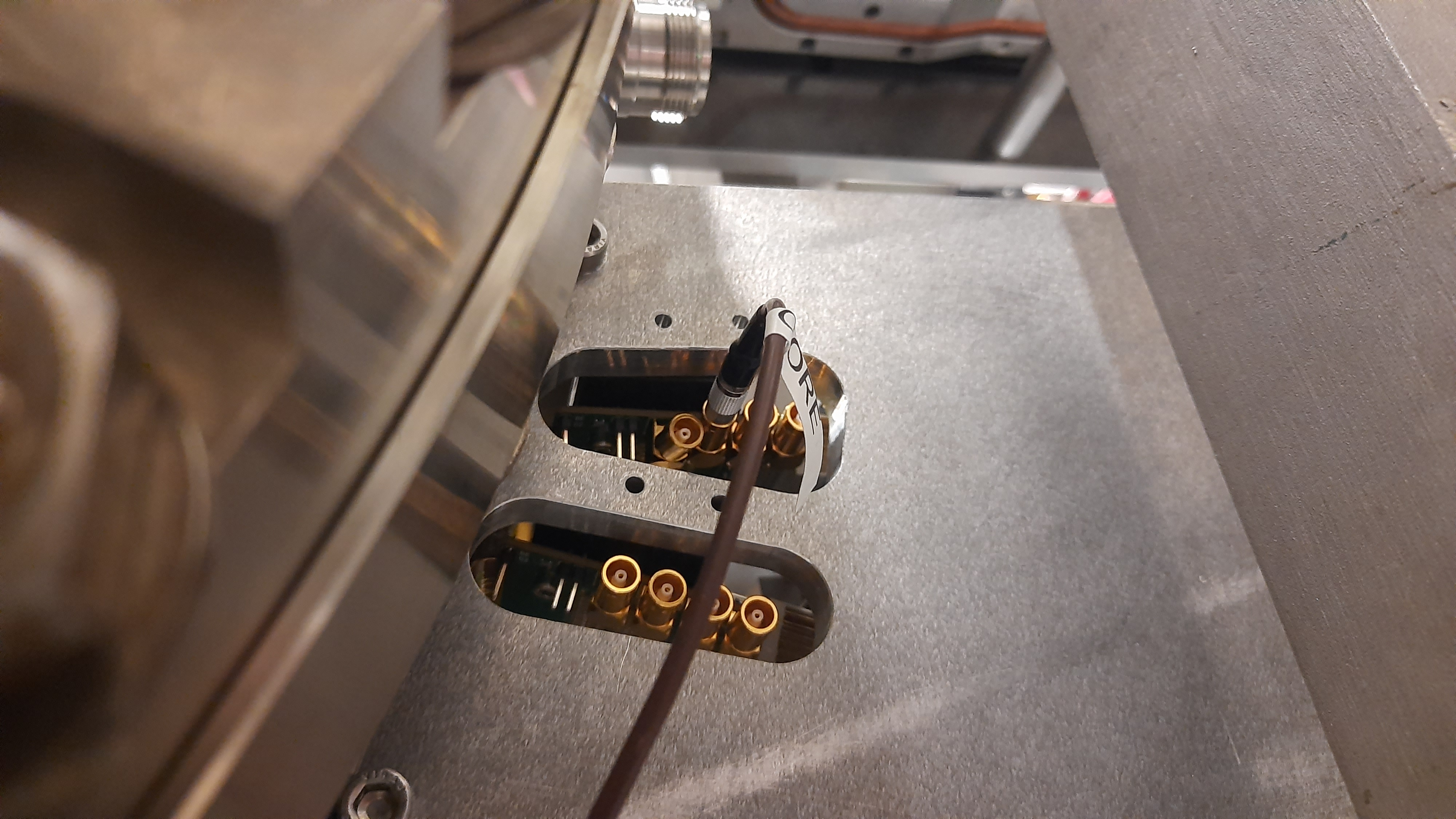
|
|
464
|
Thu Jan 11 19:57:20 2024 |
CB, JM | All FEE holders mounted |
After discussions with Davide, changed the holes in the FEE holders for the bottom-right detector to slots in order to slightly change the angle that the FEE inserts into the flexi rigid PCB. This was sufficient, with some difficulties, to insert both FEEs into the flexi rigid.
Attempted to finally mount the last two fees, the top two for the bottom-right detector, which should have been very easy. Somehow managed to break one pin on each PCB in similar spots. One is in the third column (not in use), and one is in the fourth column (in use). This latter PCB connector was unfortunately dropped while trying to dismount it, and the ERNI connector cracked. That connector can be used anymore? Cannot find spares in GSI, must be in Edinburgh?
Dismounted all the hoses from the manifold, and starting to remove teflon from the plugs. Will use instead gaskets + anti-sieze compound. Quite a number of plug thread are damaged, likely in welding. Unclear if this was the reason behind the leaks. Should be done with the manifolds tomorrow. |