| ID |
Date |
Author |
Subject |
|
222
|
Mon Feb 21 21:04:08 2022 |
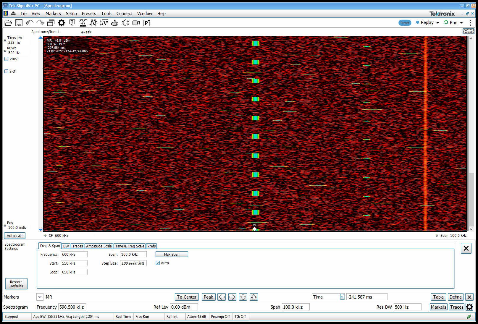
SHB, JM, CB, OH (remotely) | Schottky RF view from the beam inside |
|
| Attachment 1: pio-2022.02.21.21.54.46.895.PNG
|
|
|
221
|
Mon Feb 21 20:56:51 2022 |
SHB, JM, CB, OH (remotely) | DAQ connection for ion current |
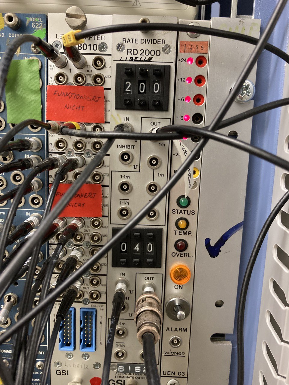
signals from ICT and CRYRADIO are now connected to AIDA2 and AIDA5 respectively. ICT is set to factor 200 and CRYRADIO to 40 for now.
(AIDA3 --> electron cooler)
|
| Attachment 1: cry.jpg
|
|
|
220
|
Mon Feb 21 18:03:58 2022 |
SHB, JM, CB, OH (remotely) | Info: signals on ion intensity for experiment |
Currently 4 possibilities to have a look at the beam, all of them are OK to check whether there is beam or not, but some of them are better for checking absolute values.
- Schottky RF signal
- Schottky zero span signal
- CRYRING Radio (signal from BPM) --> YR12DA1R
- ICT (integrated current transformer) --> YR12DT1C
absolute measurements:
- currently the beam is at 5.5 MeV/u calibrated on the flat top. The signal of ICT before is noisy but on the flat top it is well calibrated.
relative measurements:
- The signal from CRYRING radio, has a good amplifier and is frequency independent with a nice log signal. it can be used for relative measurements
- The zero span signal of Schottky can be used, but it is not reliable for measuring the number of ions since change in the control room may change the signal level.
- Schottky RF signal can be viewed by running Launcher-App using the button "VNC Tektronix RSA". The only problem is that only one instance can run, so if in the control room someone needs it, in the container it will disappear.
|
|
219
|
Mon Feb 21 17:26:19 2022 |
JM, CB, SHB, OH (remotely) | Beam ON run 53 |
21/2/22 16:00
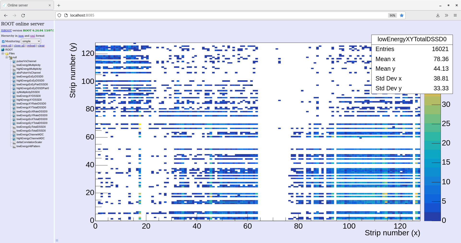
Call from main control room, beam is ON, probably has been for several hours judging by rate on xy total plot.
Changes made to online monitoring code by OH, include setting to only 1 DSSD, correct offsets from the pulser walkthrough, offline analysis capabilities and X/Y position correction.
Monitoring code restarted in CARME_SORT/build_no_output
17:31 Run 50 ended, run 51 started now beam is definitely in the ring. Tried to insert span zero schottky into aida2 correlation scalar, however rate was far too high.
18:03 Removed span zero schottky signal, started new run 52.
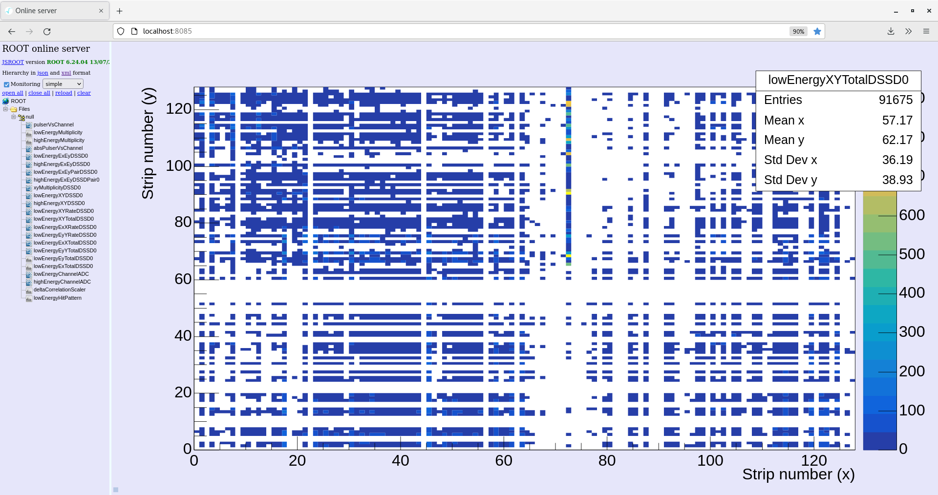
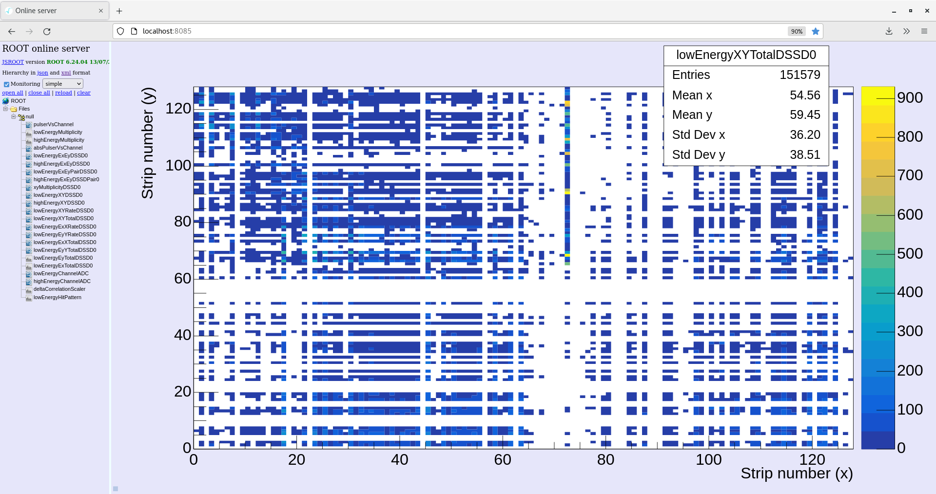
With beam ON we noticed some missing channels in the xy total plot. Aida 1 and 2 stat totals on spectrum browser show missing channels. Asic check on both to no effect. Fees power cycled.
19:57 Started run 53. Currently waiting for beam
21:20 Beam ON
1*L plots checked for aida 1, several channels showed no data (noise)
Slow comparator LEC threshold lowered to 0x32 to aida 1, checked 1*L plots and channels are now showing lots of noise. So those channels appear to be quiet using 0x64 threshold. (attachment 3)
Threshold increased back to 0x64
22:33
System checks OK -white rabbit fails on all. ~30 seperation
Temperatures OK
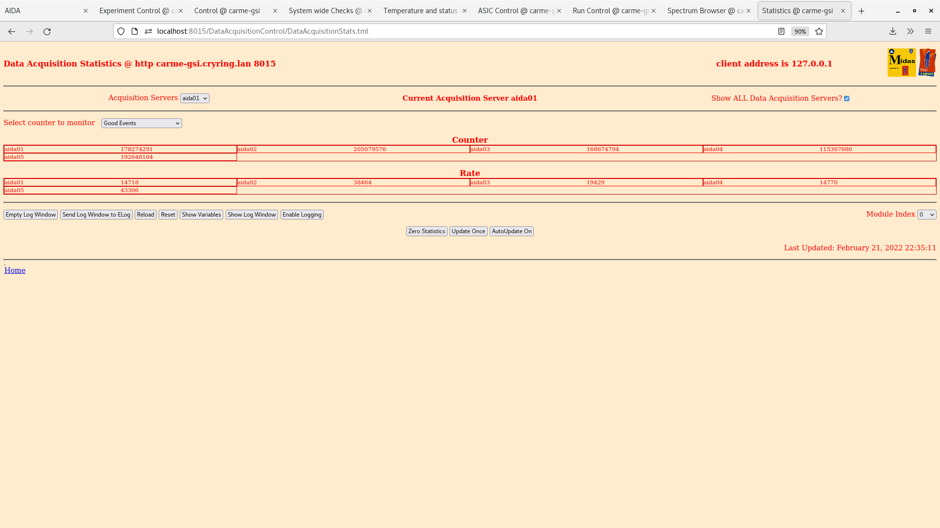
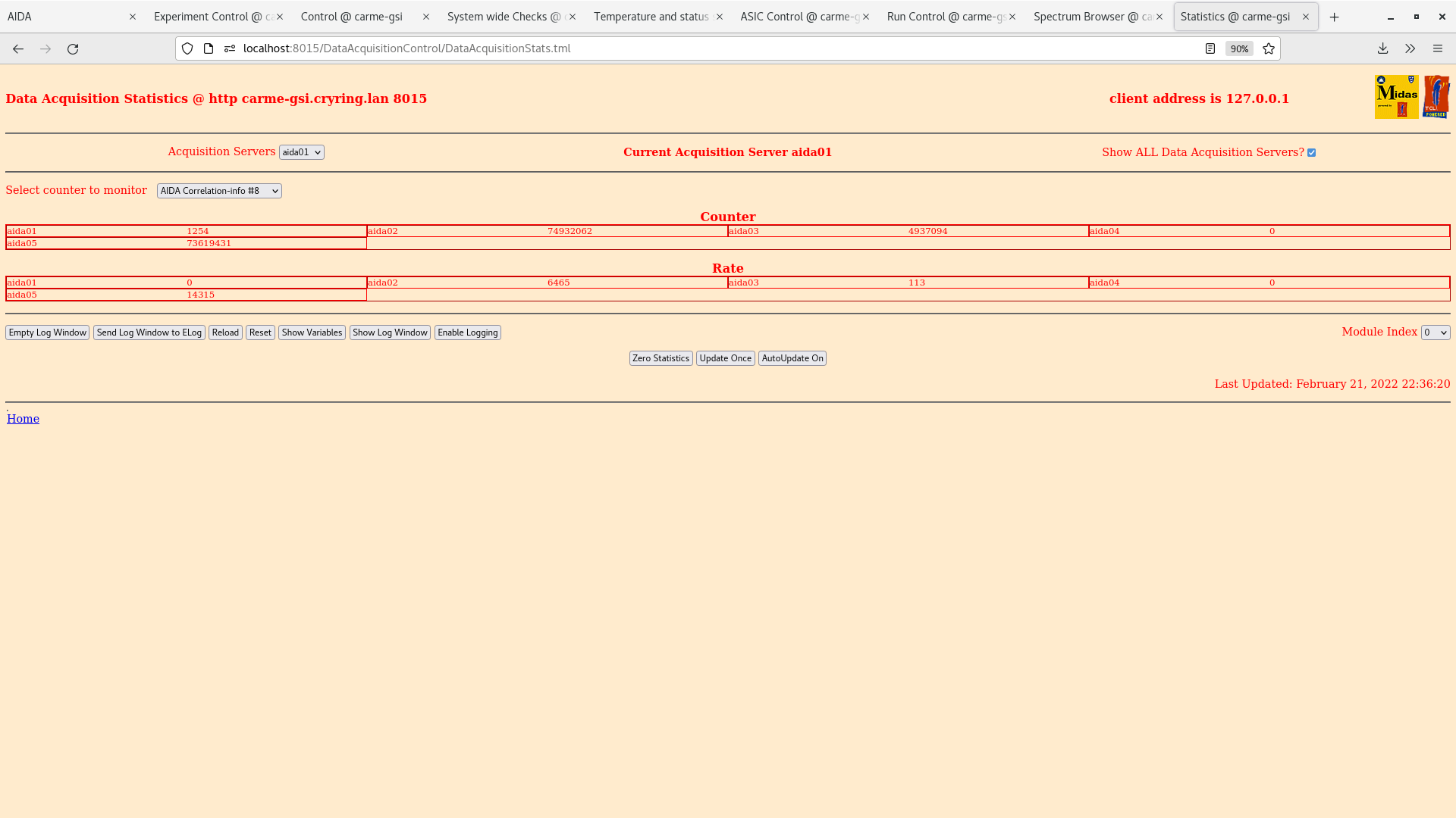
Statistics within range - new scalars added for aida02 and aida05
Data being written ~300 kb/sec
Leakage current ~3.6 uA
00:39
System checks checks OK -white rabbit fails on all. ~42 seperation
Temperatures OK
Statistics within range with new scalars
Data being written 256 kb/sec
Leakage current ~3.615 uA
XY counts dominated by hot channels - most blue pixels are ~10 counts
|
| Attachment 1: 2022-02-21_18-50-06-xyTotal.png
|
|
| Attachment 2: 2022-02-21_19-05-27-aida1-4-rate.png
|

|
| Attachment 3: 2022-02-21_22-17-54-aida1-1*L-lowerThreshold.png
|

|
| Attachment 4: 2022-02-21_22-35-19-goodEvents.png
|
|
| Attachment 5: 2022-02-21_22-35-53-ADC-dataitems.png
|

|
| Attachment 6: 2022-02-21_22-36-28-aida-correlation.png
|
|
| Attachment 7: 2022-02-21_22-58-18-Ex-histogram.png
|

|
| Attachment 8: 2022-02-21_22-59-22-XY-total.png
|
|
| Attachment 9: 2022-02-22_00-42-14-XY-total.png
|
|
|
218
|
Mon Feb 21 12:10:47 2022 |
RSS, JG | Alpha background run50 |
Beam OFF. Run started 20/2/22 18:42
System checck OK, except white rabbit all fail
Temperatures OK
Leakage current 3.59 uA.
potentiometer = 20.28 mm
11:36 OH noticed a channel in aida03 was running hot. Did an asic load check and rate returned to normal.
Online monitor also restarted.
15:06 Investigating the high rate in aida03 ASIC01 channel 11.
Looking at the waveforms it seems channel 11 is consistently different.
Attachment 1 shows a typical waveform for it
|
| Attachment 1: 220221_1506_aida03_1*W.png
|

|
|
217
|
Mon Feb 21 10:59:48 2022 |
RSS, JG | Alpha background run50 |
Beam OFF. Run started 20/2/22 18:42
System checck OK, except white rabbit all fail
Temperatures OK
Leakage current 3.59 uA.
potentiometer = 20.28 mm
11:36 OH noticed a channel in aida03 was running hot. Did an asic load check and rate returned to normal.
Online monitor also restarted.
|
|
216
|
Mon Feb 21 09:07:37 2022 |
RSS, JG | Alpha background run50 |
Beam OFF. Run started 20/2/22 18:42
System checck OK, except white rabbit all fail
Temperatures OK
Leakage current 3.57 uA.
potentiometer = 20.28 mm
|
|
215
|
Mon Feb 21 08:05:45 2022 |
RSS, JG | Alpha background run50 |
Beam OFF. Run started 20/2/22 18:42
System checck OK, except white rabbit all fail
Temperatures OK
Leakage current 3.57 uA.
potentiometer = 20.28 mm
|
|
214
|
Sun Feb 20 22:04:21 2022 |
JM, CB | Alpha Background run 50 |
Beam OFF. Run started 20/2/22 18:42
Fast comparator threshold HEC set to 0xff for all fees and asics to combat high energy noise bursts.
Electron cooler scalar plugged back into aida03 ~3000 per sec.
System checck OK, except white rabbit all fail
Temperatures OK
Leakage current 3.638 uA.
Statistics rates in noraml range, aida03 slightly higher as expected with scalar. |
|
213
|
Sat Feb 19 20:08:43 2022 |
JM, CB | Beam ON run 49 |
Run started 19/2/22 21:05. Beam ON
Temperatures OK
System wide checks OK - white rabbit fails on all.
Statistics are within normal range (10-20K goodevents)
Leakage current 3.6 uA
potentiometer = 20.28 mm
20/2/22
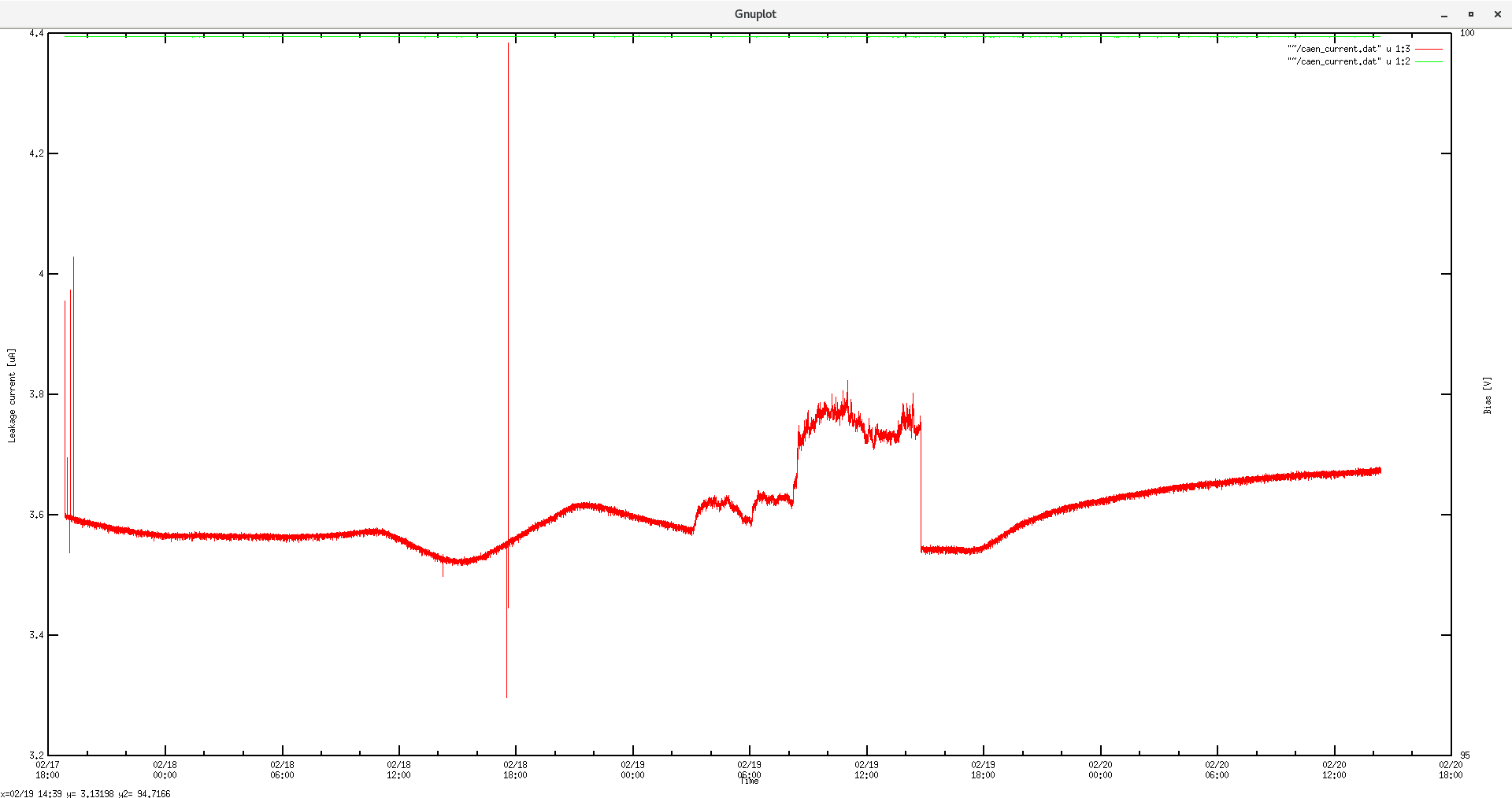
Leakage current ~3.675 uA. Looks stable now motors can not move (attachment 1)
potentiometer = 20.28 mm
Temperatures OK
System wide checks OK - white rabbit fails all
Statistic within normal range (see attachment 2 - ADC data items) Counter for aida 1 and aida 2 much higher due to noise bursts (elog 212)
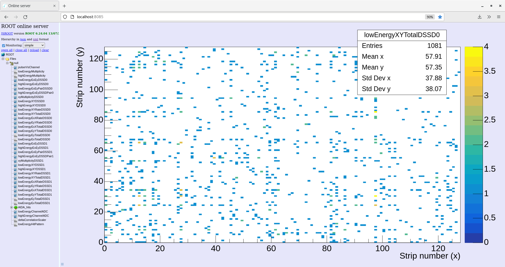
XY total plot (attachment 3)
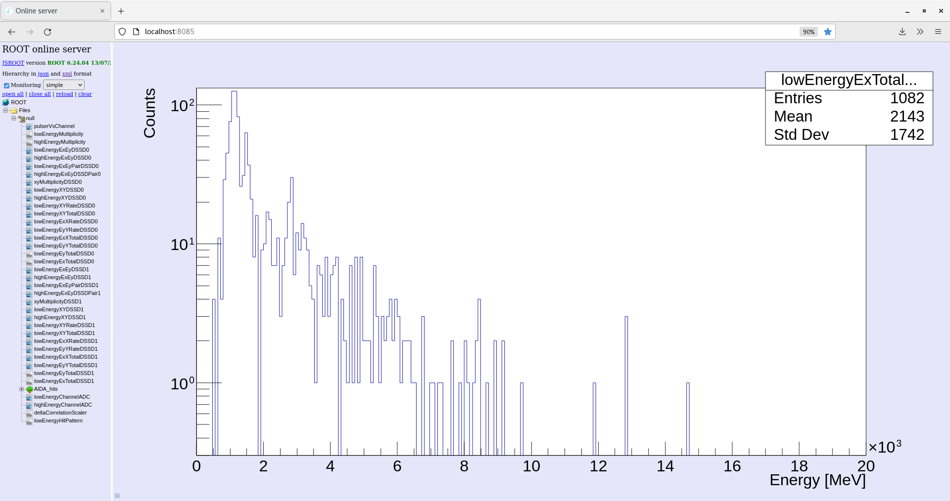
Low energy Ex histogram (attachment 4)
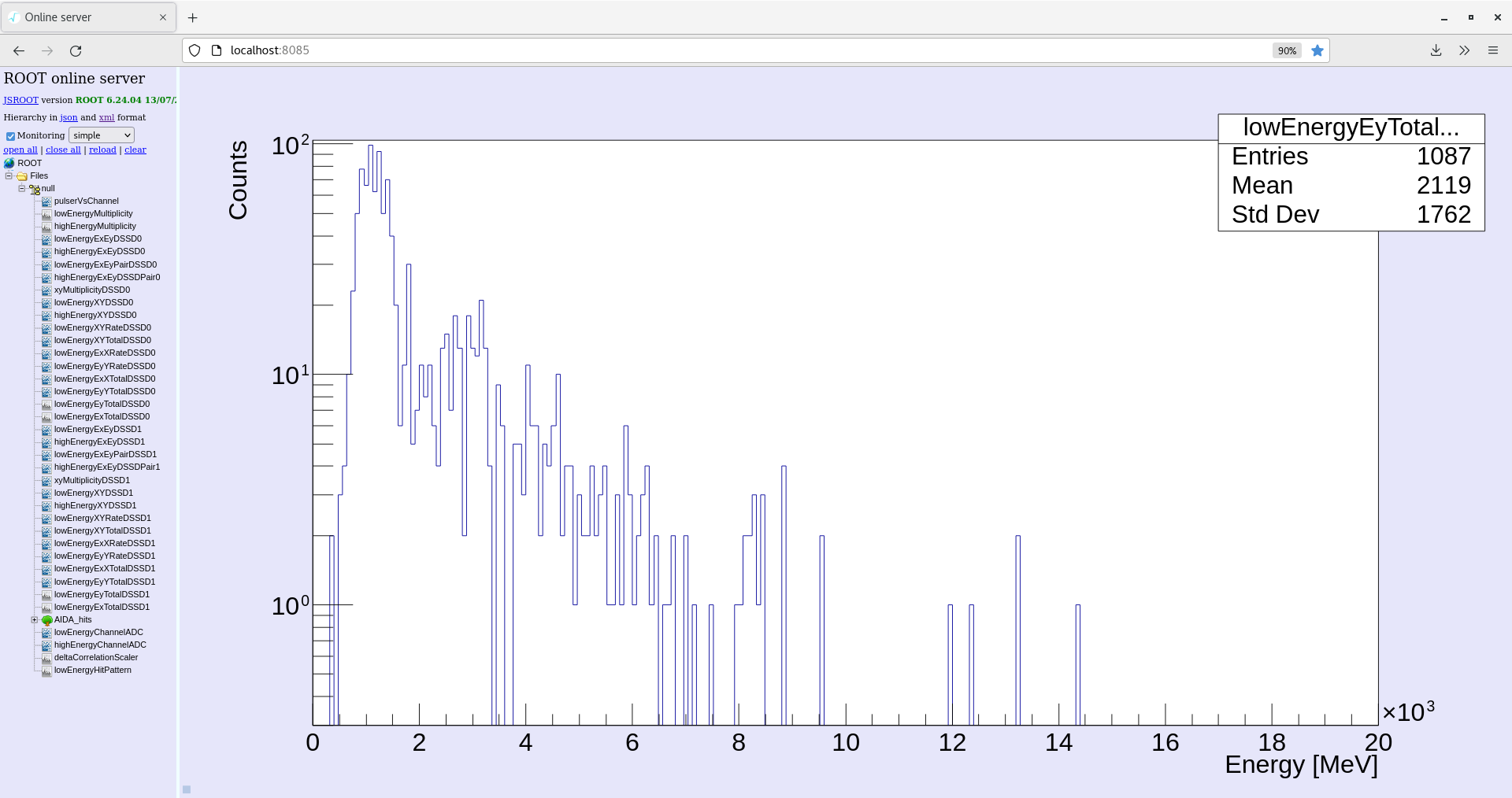
Low energy Ey histogram (attachment 5)
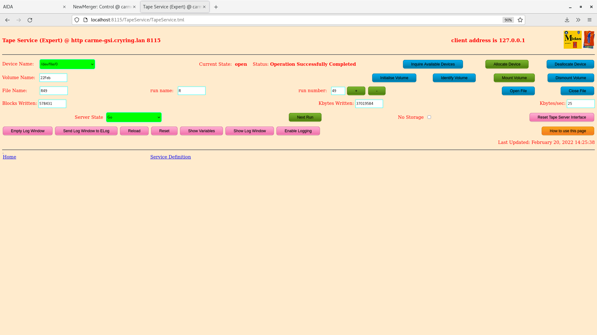
Tape Server data written (attachment 6)
Run end 20/2/22 15:08 |
| Attachment 1: 2022-02-20_14-16-16-leakage-current.png
|
|
| Attachment 2: 2022-02-20_14-18-07-statistic-ADCdata.png
|

|
| Attachment 3: 2022-02-20_14-20-43-xyTotal.png
|
|
| Attachment 4: 2022-02-20_14-24-19-LowEnergy-ExTotal.png
|
|
| Attachment 5: 2022-02-20_14-28-02-LowEnergy-EyTotal.png
|
|
| Attachment 6: 2022-02-20_14-25-45-Tape-server-data-written.png
|
|
|
212
|
Sat Feb 19 14:51:58 2022 |
JM, CB | Burst high energy noise |
Noticed bursts of high energy noise on aida01 and aida02 during run 47 and 48.
Good events rate jumps from 10-20k range to 250k. ADC data items rate jumps from 0-1 to 2k. Data rate being written increases to ~2500 kb/s from ~20 kb/s
Effect appears short lived ~30s at a time. On 18/2/22 the asic was check loaded which appeared to remove the increased rate but due to the time taken to asic check the burst had already finished.
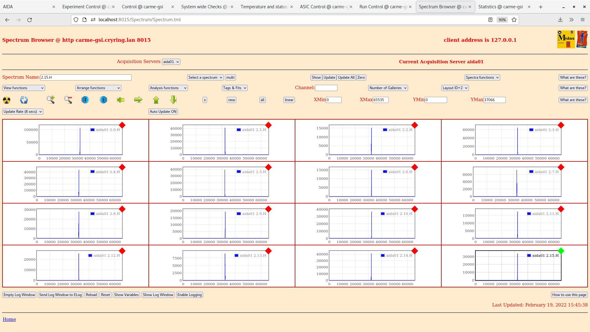
Asic 2 on aida01 and asic 1 on aida02 are affected. See attached plots.
Fast comparator threshold HEC currently set to 0x2 for all
Zoomed in region of aida 1 asic 2 and the same region for asic 1 to see the difference are attached.
|
| Attachment 1: 2022-02-19_15-50-50-aida1-4-stat-logscale.png
|

|
| Attachment 2: 2022-02-19_15-47-13-aida1-2*H.png
|
|
| Attachment 3: 2022-02-19_15-49-48-aida2-1*H.png
|

|
| Attachment 4: 2022-02-20_14-01-40-aida1-2*H.png
|

|
| Attachment 5: 2022-02-20_14-02-55-aida1-1*H.png
|

|
|
211
|
Fri Feb 18 20:31:33 2022 |
JM, CB | Alpha Background run 48 |
Alpha background started with beam ON - run47. Run started 16:49 18/2/22 (beam subsequently found to be OFF)
Beam energy 4 keV, beam lifetime ~ 100 ms
Noticed aida01 and aida02 were showing increased good event rates to ~250,000, effect seen on spectrum browser and data writing rate increased to ~2500 kb/sec from ~20 kb/sec. ASIC check on the affected fees brought rates back to normal range 10-20k good events. Multiple instances occurred in a row on run47 so fees were power cycled. Run ended 17:21
Run 48 started after power cycle
Run start 17:42, beam OFF ~18:30-19:00 for access to the cave to aid allignment of the gas jet target.
Rates remain stable until ~20:00. Aida01 and 02 show increased rates, asic check -> back to normal range.
Beam ON 21:43
All system checks OK. All rates OK. Leakage current ~3.62 uA.
14:00 19/2/22
Beam OFF during 18/2/22 due to an interlock controlled by main control room unknown to us. Beam has been OFF.
Leakage current plot attached. System checks OK, except white rabbit, all fail.
Motors were at 26mm potentiometer opposed to 20.2mm which was the set point (fully out 19mm). Motors dragged in as pneumatic was not fully out. Likely result of pneumatic out valve being closed. Pneumatic fully out, potentometer back to 20.2mm and leakage current drop from ~3.75 uA to 3.54uA.
Run ended 21:00 |
| Attachment 1: 2022-02-19_14-45-25-leage-current.png
|

|
|
210
|
Fri Feb 18 13:03:02 2022 |
RSS, ML, CB | Alpha background run46 |
14:00
Check Leakage current: (see attachment 4)
Check NewMerger tab: (see attachment 2)
Check Fee temperatures: all green (see attachment 1)
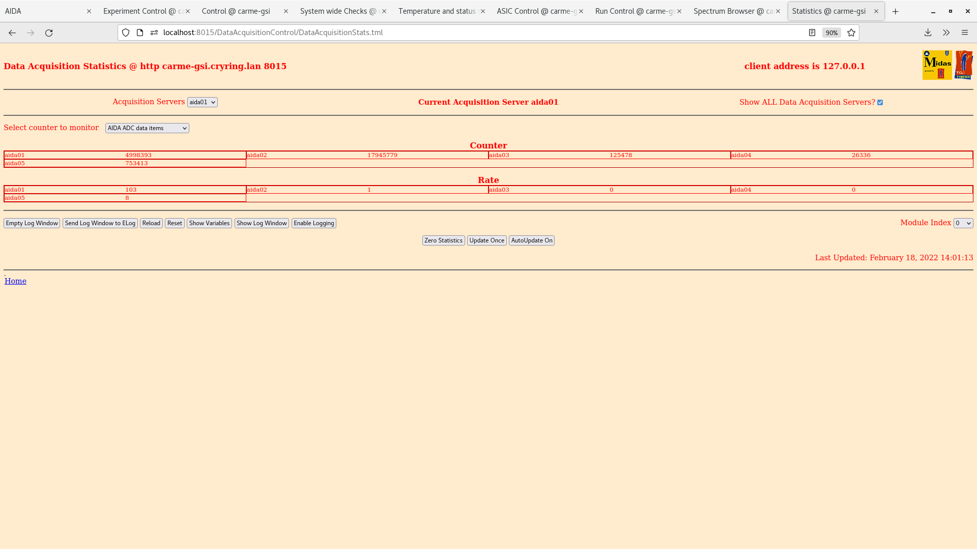
Check statistics tab: ADC data items (see attachment 11)
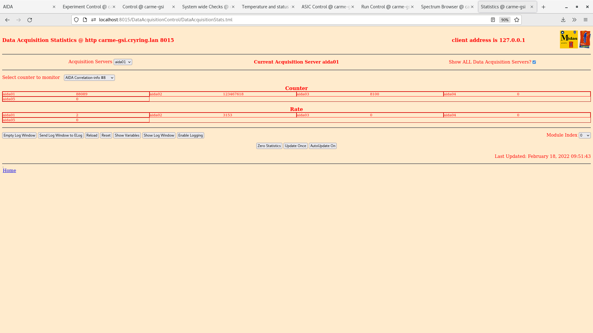
ADC coincidence-info #8 (see attachment 10)
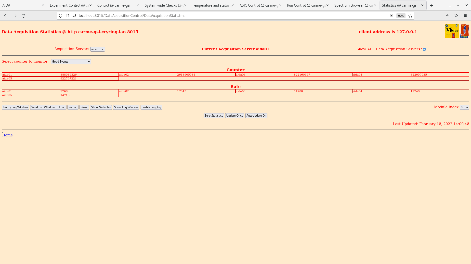
Good events (see attachment 9)
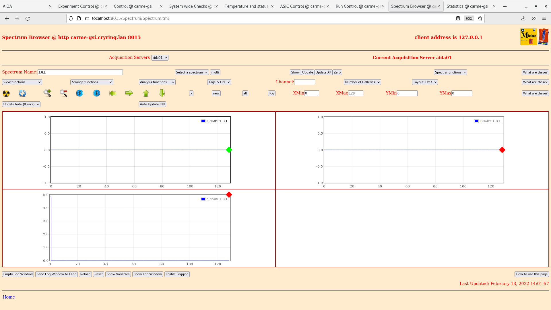
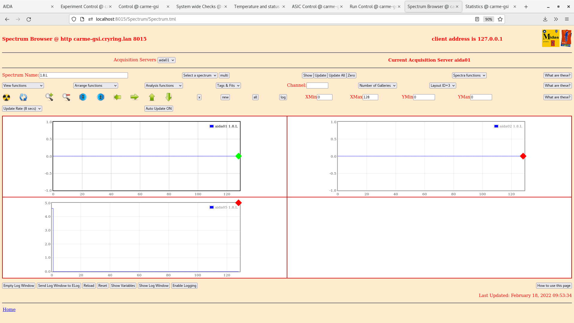
Check Spectrum Browser tab: (see attachment 6)
Check the following plots:
LowEnergyXYTotalDSSD0 (see attachment 7)
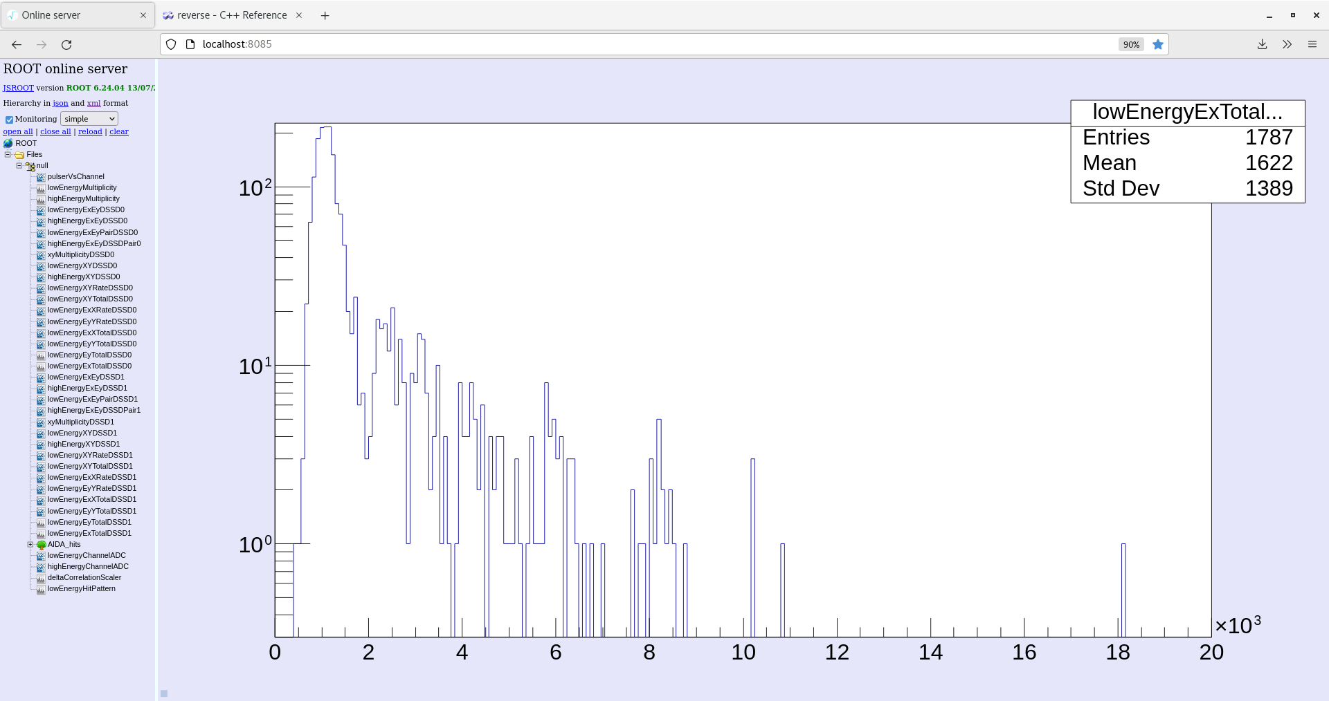
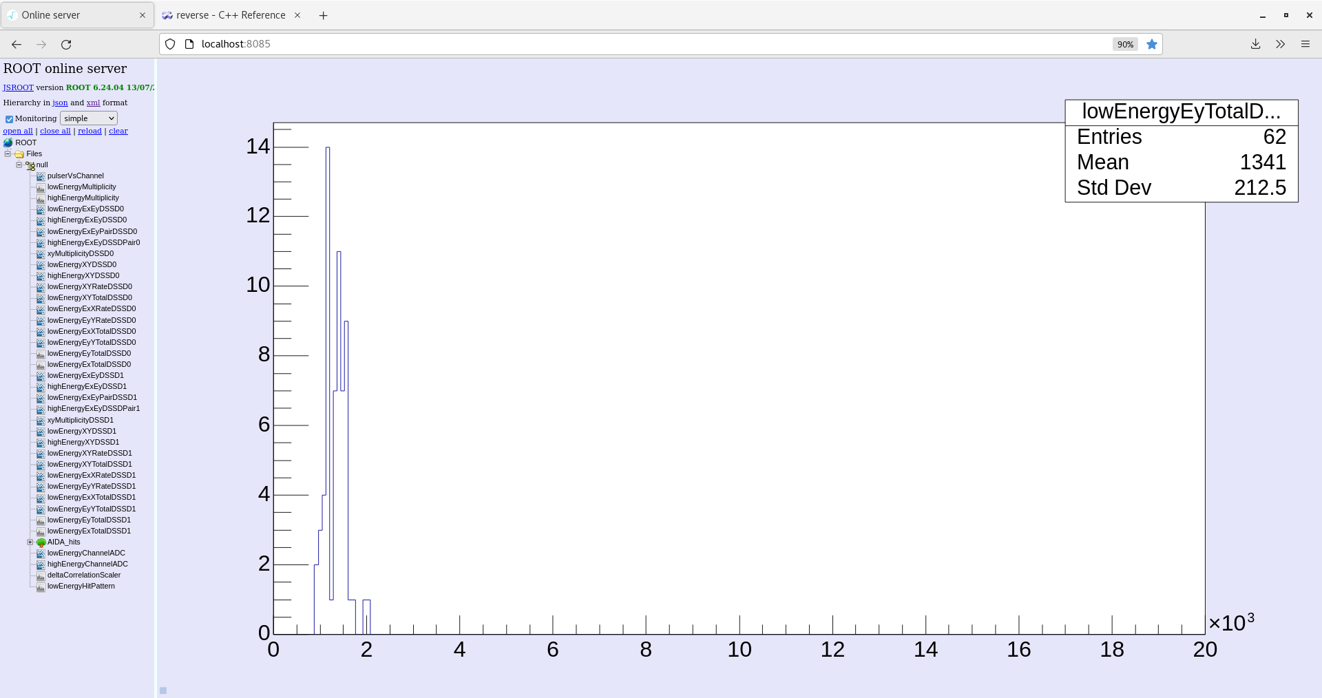
LowEnergyExTotal (see attachment 8)
LowEnergyEyTotal (see attachment 5)
Check system wide checks tab: White Rabbit error counter test result: Passed 0, Failed 5 (see attachment 3)
Data taking was stopped at 14:04. |
| Attachment 1: temp-2022-02-18_13-59-30.png
|

|
| Attachment 2: merger-2022-02-18_13-58-41.png
|

|
| Attachment 3: system-2022-02-18_13-59-57.png
|

|
| Attachment 4: leakage-2022-02-18_13-59-02.png
|

|
| Attachment 5: ey-total-2022-02-18_13-57-46.png
|

|
| Attachment 6: spectrum-2022-02-18_14-02-02.png
|
|
| Attachment 7: xy-total-2022-02-18_14-02-23.png
|

|
| Attachment 8: ex-energy-2022-02-18_13-56-32.png
|
|
| Attachment 9: good-event-2022-02-18_14-00-53.png
|
|
| Attachment 10: correlation-2022-02-18_14-00-27.png
|

|
| Attachment 11: adc-data-item-2022-02-18_14-01-17.png
|
|
|
209
|
Fri Feb 18 11:07:52 2022 |
RSS, ML, CB | Alpha background run46 |
12:00
Check Leakage current: (see attachment 4)
Check NewMerger tab: (see attachment 2)
Check Fee temperatures: all green (see attachment 1)
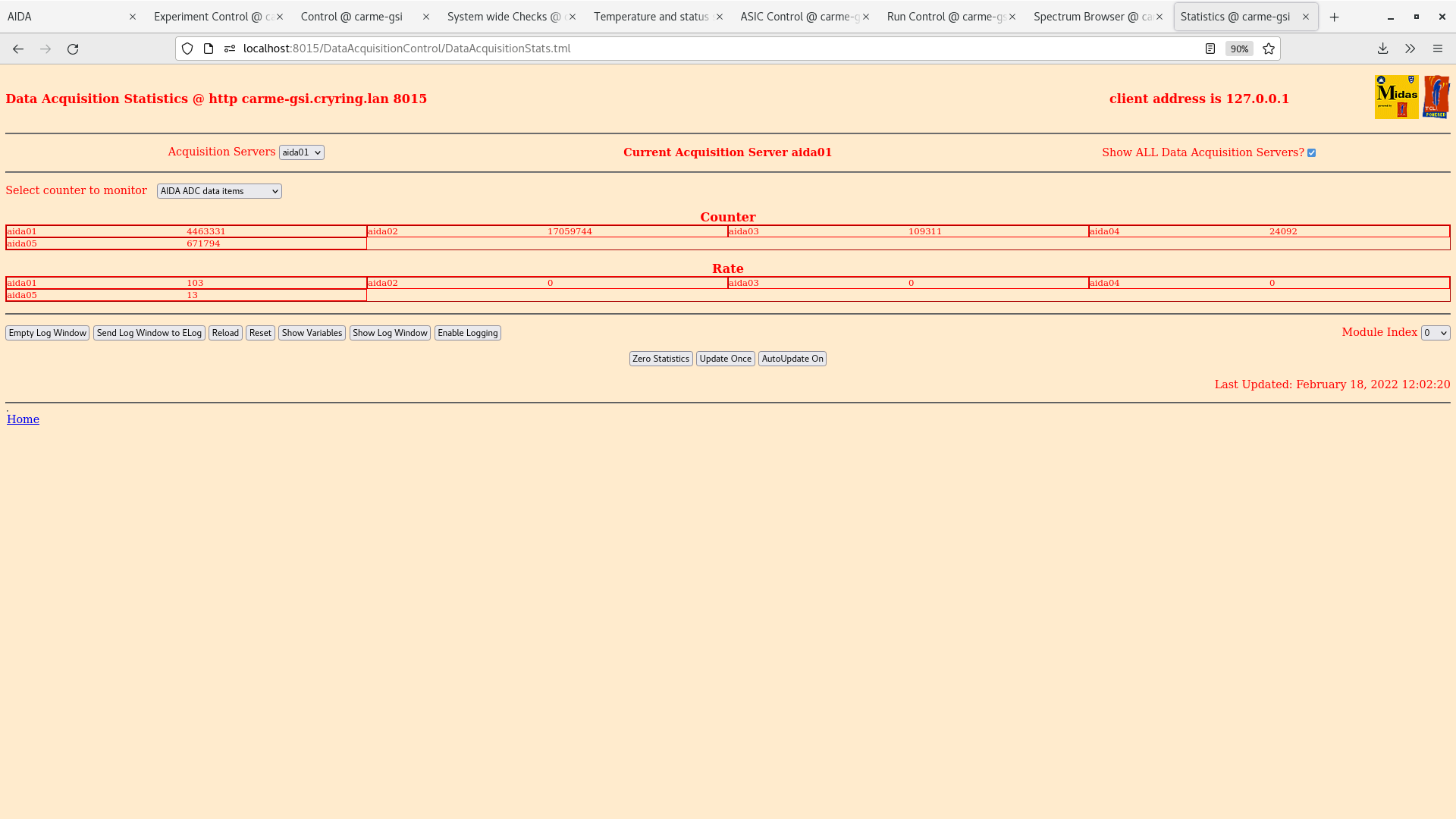
Check statistics tab: ADC data items (see attachment 9)
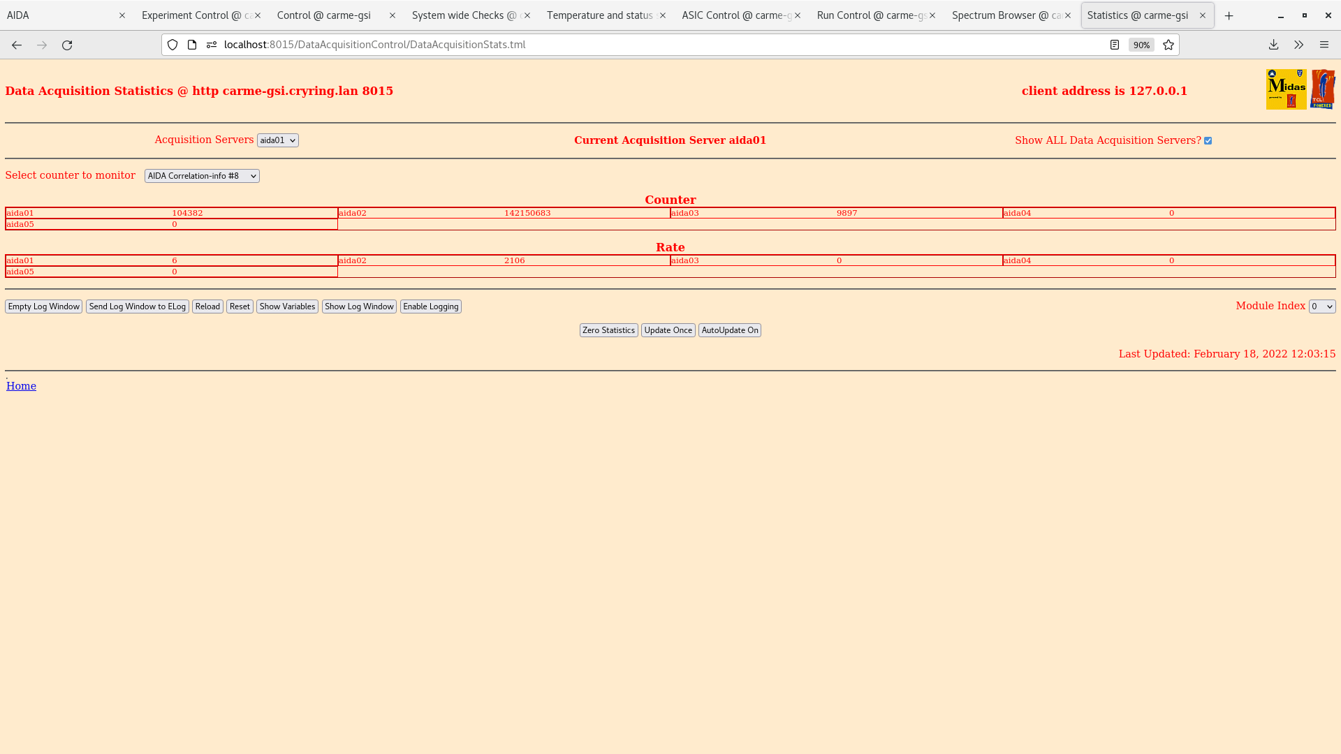
ADC coincidence-info #8 (see attachment 8)
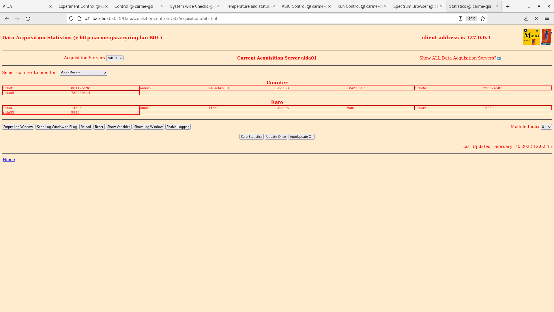
Good events (see attachment 7)
Check Spectrum Browser tab: (see attachment 10)
Check the following plots:
LowEnergyXYTotalDSSD0 (see attachment 11)
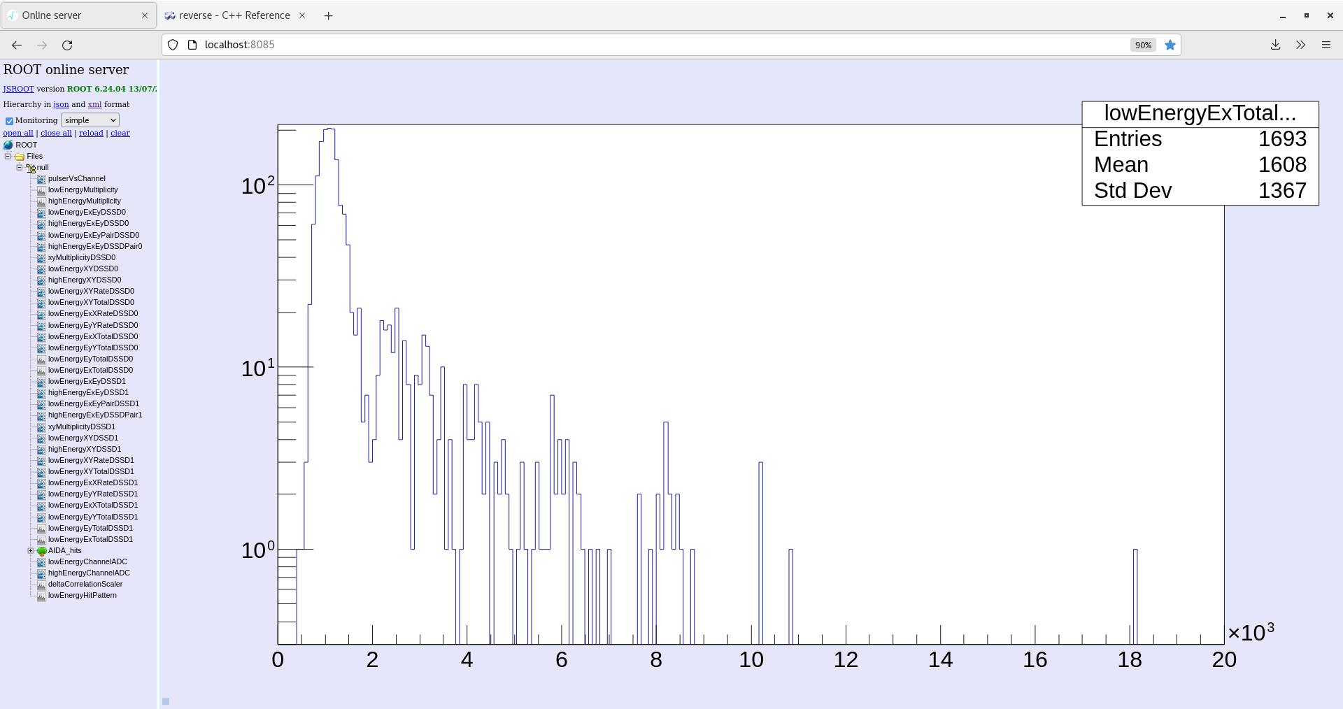
LowEnergyExTotal (see attachment 5)
LowEnergyEyTotal (see attachment 6)
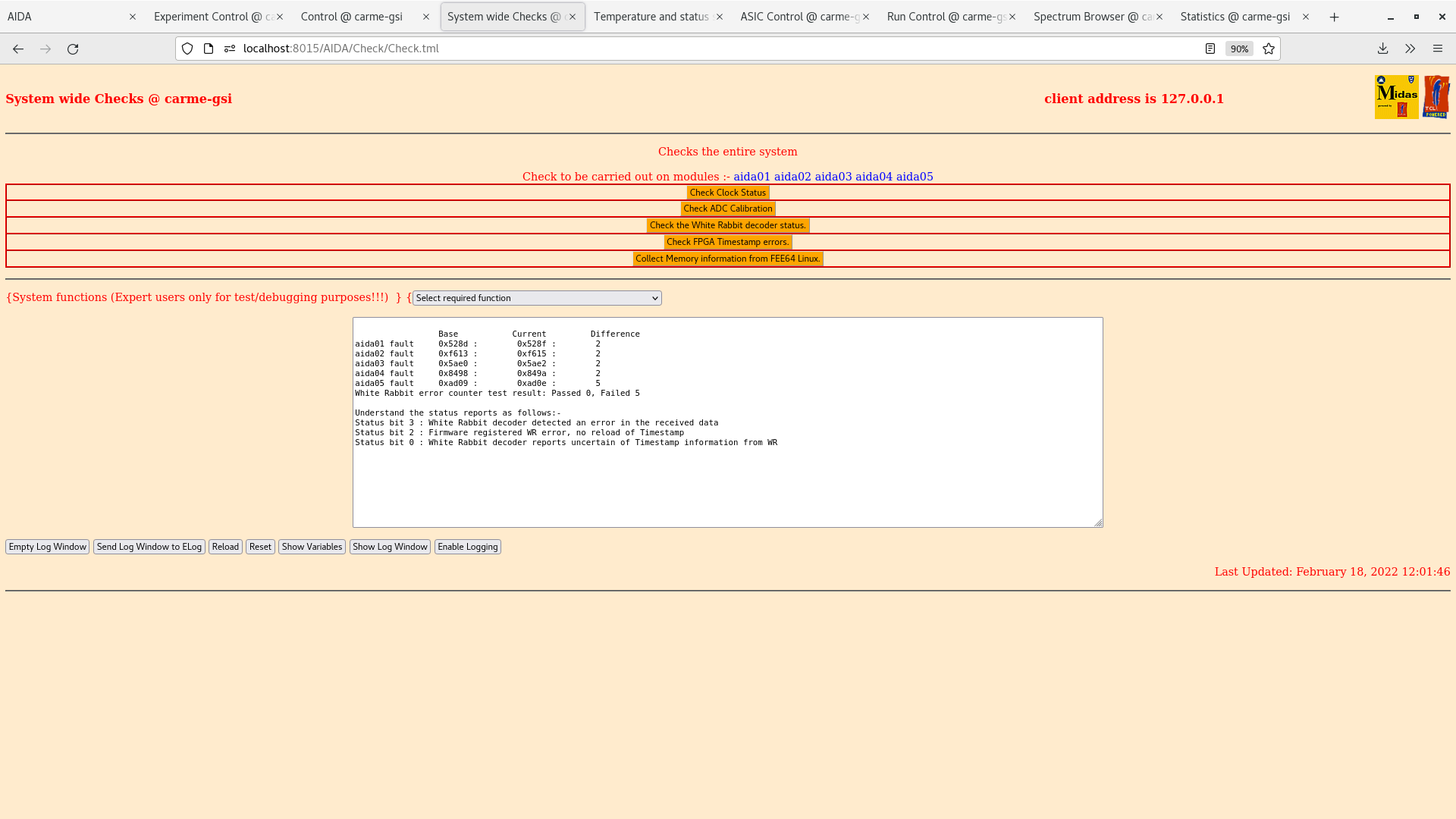
Check system wide checks tab: White Rabbit error counter test result: Passed 0, Failed 5 (see attachment 3) |
| Attachment 1: temp-2022-02-18_12-01-21.png
|

|
| Attachment 2: merger-2022-02-18_12-00-10.png
|

|
| Attachment 3: system-2022-02-18_12-01-52.png
|
|
| Attachment 4: leakage-2022-02-18_12-00-43.png
|

|
| Attachment 5: energy-ex-2022-02-18_12-07-07.png
|
|
| Attachment 6: energy-ey-2022-02-18_12-05-29.png
|

|
| Attachment 7: good-event-2022-02-18_12-02-49.png
|
|
| Attachment 8: correlation-2022-02-18_12-03-19.png
|
|
| Attachment 9: adc-data-item2022-02-18_12-02-25.png
|
|
| Attachment 10: spectrum_browser-2022-02-18_12-03-55.png
|

|
| Attachment 11: energy-xy-total-2022-02-18_12-14-29.png
|

|
|
208
|
Fri Feb 18 08:58:08 2022 |
RSS, ML, CB | Alpha background run46 |
10:00
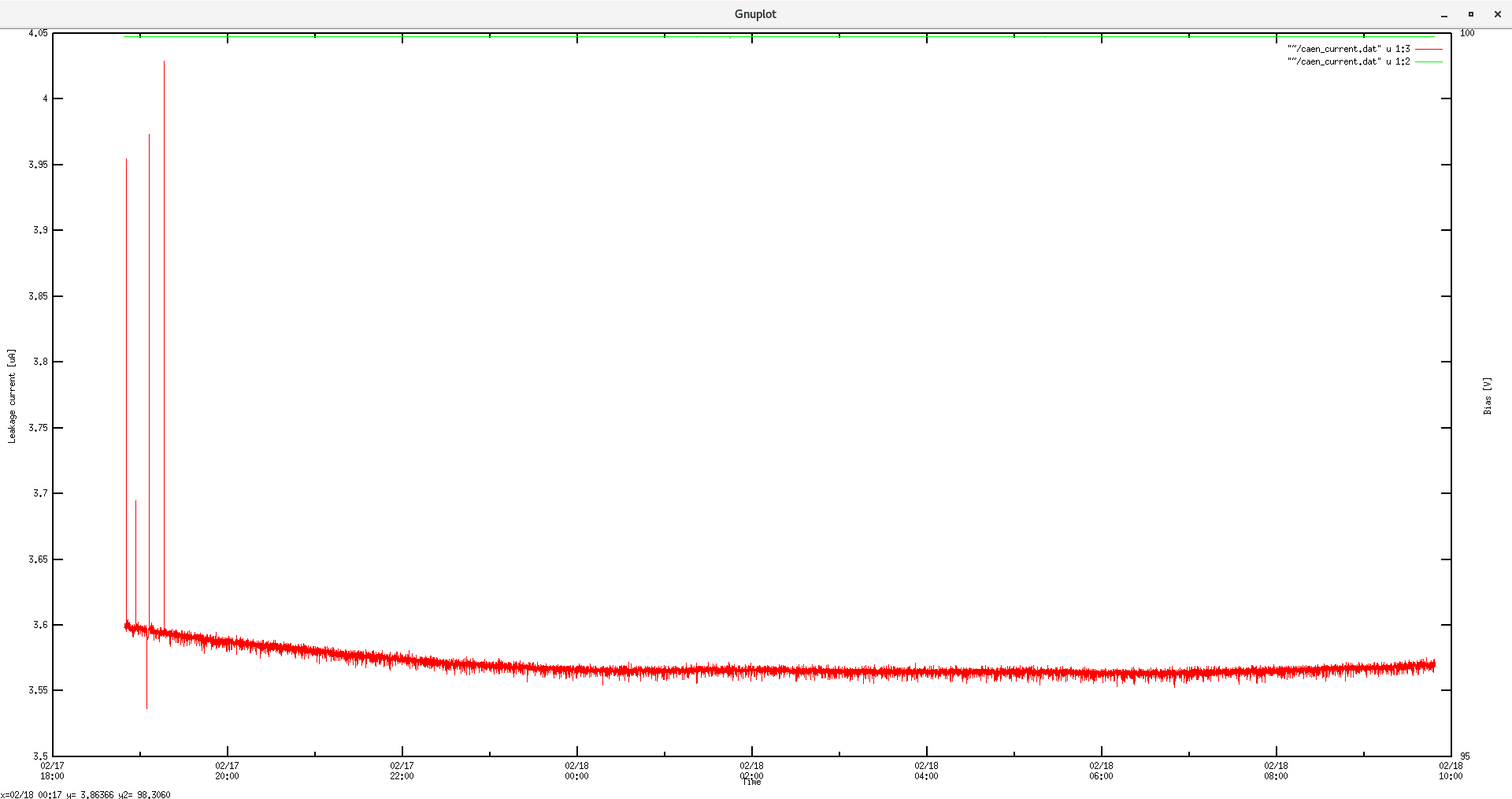
Check Leakage current: (see attachment 2)
Check NewMerger tab: (see attachment 5)
Check Fee temperatures: all green (see attachment 1)
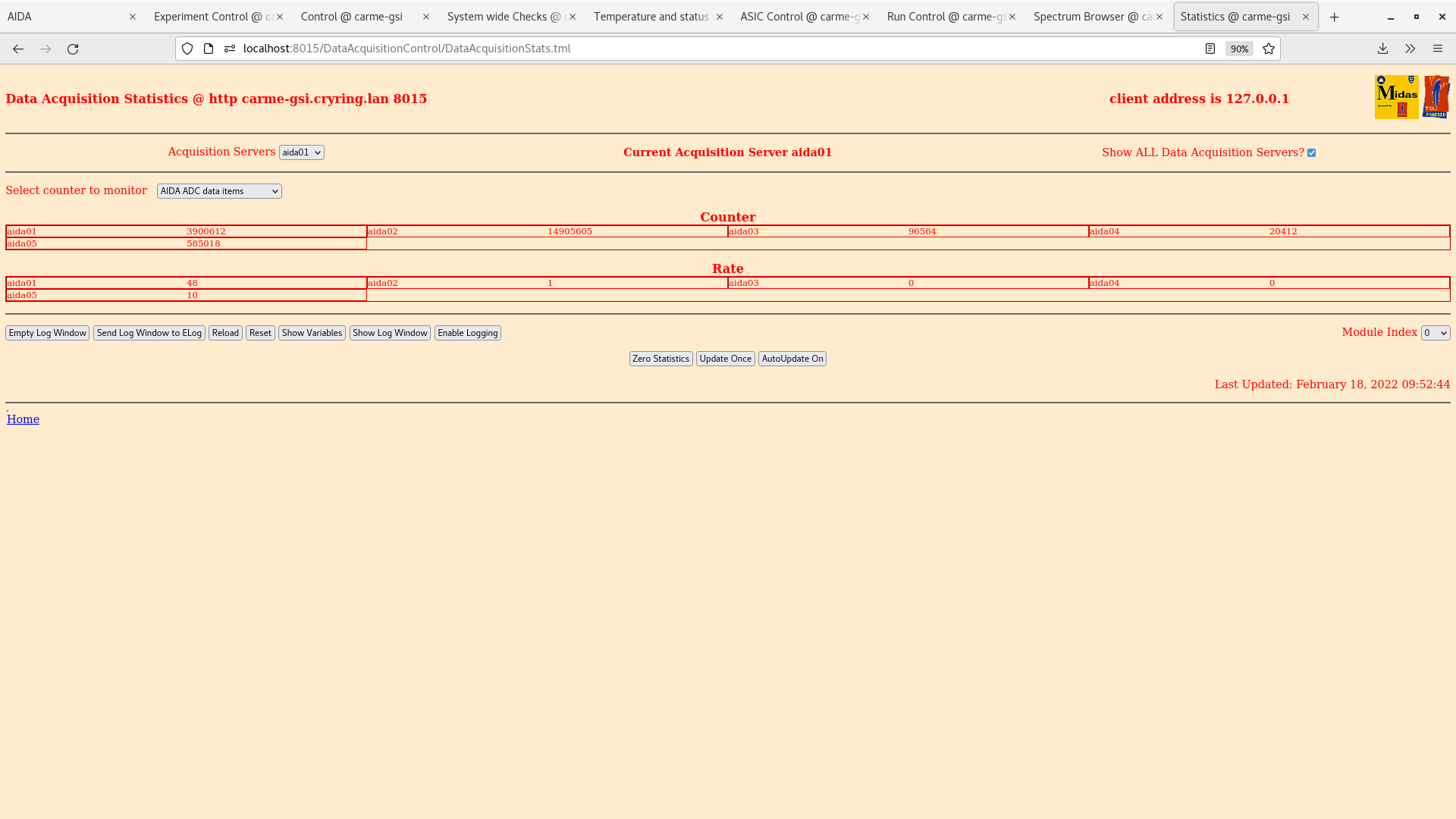
Check statistics tab: ADC data items (see attachment 3)
ADC coincidence-info #8 (see attachment 6)
Good events (see attachment 7)
Check Spectrum Browser tab: (see attachment 9)
Check the following plots:
LowEnergyXYTotalDSSD0 (see attachment 9)
LowEnergyExTotal (see attachment 10)
LowEnergyEyTotal (see attachment 11)
Check system wide checks tab: White Rabbit error counter test result: Passed 0, Failed 5 (see attachment 8) |
| Attachment 1: temp-2022-02-18_09-50-32.png
|

|
| Attachment 2: leakage-2022-02-18_09-44-34.png
|
|
| Attachment 3: adc-data-2022-02-18_09-52-48.png
|
|
| Attachment 4: energy_ex_2022-02-18_09-55-48.png
|

|
| Attachment 5: new-merger-2022-02-18_09-44-10.png
|

|
| Attachment 6: correlation-2022-02-18_09-51-48.png
|
|
| Attachment 7: good-events-2022-02-18_09-52-17.png
|

|
| Attachment 8: system-wide-2022-02-18_09-51-08.png
|

|
| Attachment 9: spectrum-browser-2022-02-18_09-53-52.png
|
|
| Attachment 10: energy-xy-total-2022-02-18_10-12-10.png
|

|
| Attachment 11: energy-ey-2022-02-18_09-58-53.png
|

|
|
207
|
Thu Feb 17 18:19:16 2022 |
JM, CB, SD | Alpha Background run 46 |
Both GSI vacuum group and edinburgh ion gauges OFF
Fees power cycled. All system checks OK.
Writing to file, alpha background overnight.
Moved detector IN 2mm. Noise appears reduced with any distance moved in so overnight spectra to be taken while IN. Not moving further in as possible beam tomorrow.
22:44
Leakage current stable, slowly decreasing ~3.57 uA (attachment 1)
Statistics look OK
Temperatures OK
System wide check all pass - OK
Noise appears much reduced on spectrum Browser channels. (attachement 2). Compared to same plot on elog 197
XYtotal per pixel (attachment 3)
Ex histogram (attachment 4)
|
| Attachment 1: 2022-02-17_22-41-45-leakageCurrent.png
|

|
| Attachment 2: 2022-02-17_22-51-07-aida1-3*L.png
|

|
| Attachment 3: 2022-02-17_22-54-06-XYTotal.png
|

|
| Attachment 4: 2022-02-17_22-56-38-ExHist.png
|

|
|
206
|
Thu Feb 17 16:26:27 2022 |
JM, CB, SD | Gauges OFF, Pulser Movement tests |
Edinburgh group ion gauge turned OFF -> decrease in leakage current from 10.05 uA to 6.5 uA
GSI vacuum group ion gauge turned OFF -> decrease in leakage current from 6.5 uA to 3.63 uA
GSI large ion pump turned ON -> no effect on leakage current
Motors moved IN the same as elog 201. No significant increase in leakage current as moved further into the chamber (attachment 1). Pulser widths follow similar path as previous tests. Aida1 and 2 statrt with larger pulser widths which reduce as are moved into the chamber. Aida3,4 start lower than aida1,2 and remain at same level throughout. (attachment2)
RF ring signal removed from aida5. Data rate dropped back to ~20 kb/sec, Merger rate ~80,000 items/sec
Noise peak on aida1 appears reduced after gauges switched OFF with detector fully out (attachment 3) coompare to elog 201
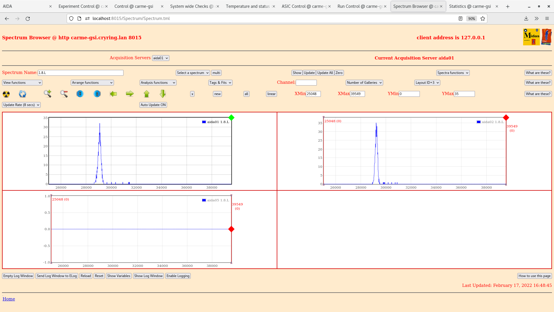
Noise peak is removed once detector is moved in. (attachment 4)
Ey histogram (attachment 5) shows multiple peaks for the same pulser amplitude.
XY total pixels plot (attachment 6)
1.8 waveforms for aida 1,2,5 (attachment 7) |
| Attachment 1: leakage-potentiometer2_1.png
|

|
| Attachment 2: pulserWidth_potentiometer2.png
|

|
| Attachment 3: 2022-02-17_16-54-27aida125-1.8*L-fullyout.png
|

|
| Attachment 4: 2022-02-17_16-48-55-aida125-1.8*L-fullyin.png
|
|
| Attachment 5: 2022-02-17_17-29-25-Eyhistogram-pulserON.png
|

|
| Attachment 6: 2022-02-17_18-40-14-xyTotal-pulser.png
|

|
| Attachment 7: 2022-02-17_22-59-53-aida125-1.8*W.png
|

|
|
205
|
Thu Feb 17 15:09:40 2022 |
JM,CB,SD | Alpha background run44 |
16:09
Check Leakage current: (see attachment 1)
Check NewMerger tab: (see attachment 3)
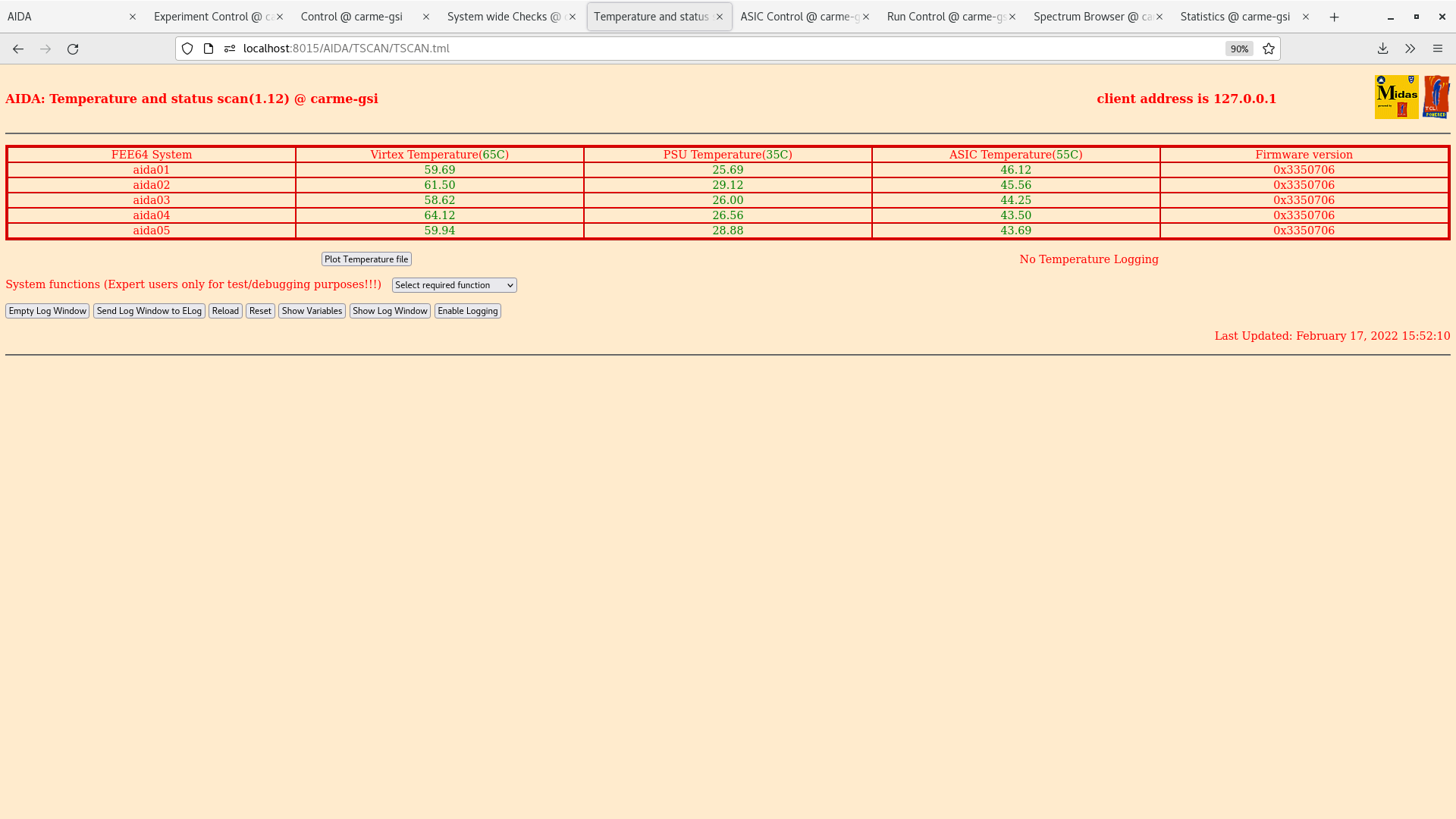
Check Fee temperatures: all green (see attachment 5)
Check statistics tab: ADC data items (see attachment 2)
ADC coincidence-info #8 (see attachment 6)
Good events (see attachment 4)
Check Spectrum Browser tab: (see attachment 10)
Check the following plots:
LowEnergyXYTotalDSSD0 (see attachment 9)
LowEnergyExTotal (see attachment 7)
LowEnergyEyTotal (see attachment 8)
Check system wide checks tab: White Rabbit error counter test result: Passed 0, Failed 5 (see attachment 11)
Run stopped for pulser tests 16:13 |
| Attachment 1: 2022-02-17_16-04-11_lowEnergyExTotal.png
|

|
| Attachment 2: 2022-02-17_16-05-03_lowenergyEytotal.png
|
|
| Attachment 3: 2022-02-17_16-03-06_lowEnergyTotalDSSSD.png
|

|
| Attachment 4: 2022-02-17_15-54-12_leakagecurrent.png
|

|
| Attachment 5: 2022-02-17_15-53-25_Merger.png
|

|
| Attachment 6: 2022-02-17_15-52-29_Temperature.png
|
|
| Attachment 7: 2022-02-17_15-50-57_GoodEvents.png
|

|
| Attachment 8: 2022-02-17_15-49-12._AIDA_ADC_dataitems.png
|

|
|
204
|
Thu Feb 17 13:12:19 2022 |
RSS, AG | Alpha background run43 |
14:00
Check Leakage current: (see attachment 1)
Check NewMerger tab: (see attachment 3)
Check Fee temperatures: all green (see attachment 5)
Check statistics tab: ADC data items (see attachment 2)
ADC coincidence-info #8 (see attachment 6)
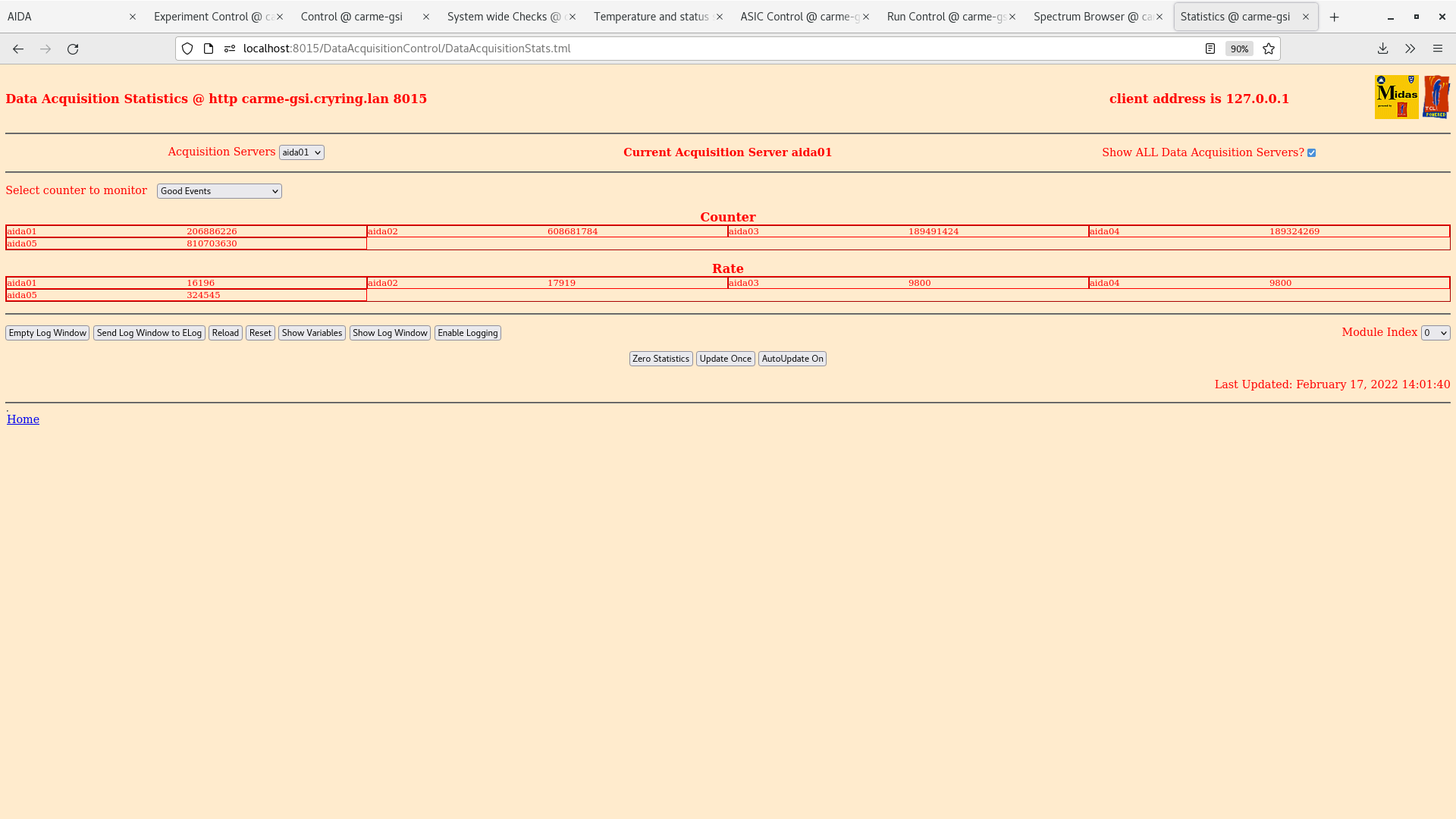
Good events (see attachment 4)
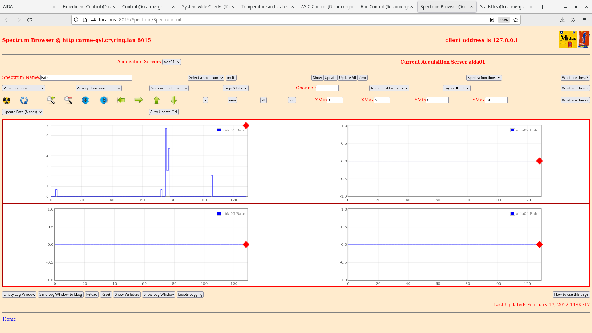
Check Spectrum Browser tab: (see attachment 10)
Check the following plots:
LowEnergyXYTotalDSSD0 (see attachment 9)
LowEnergyExTotal (see attachment 7)
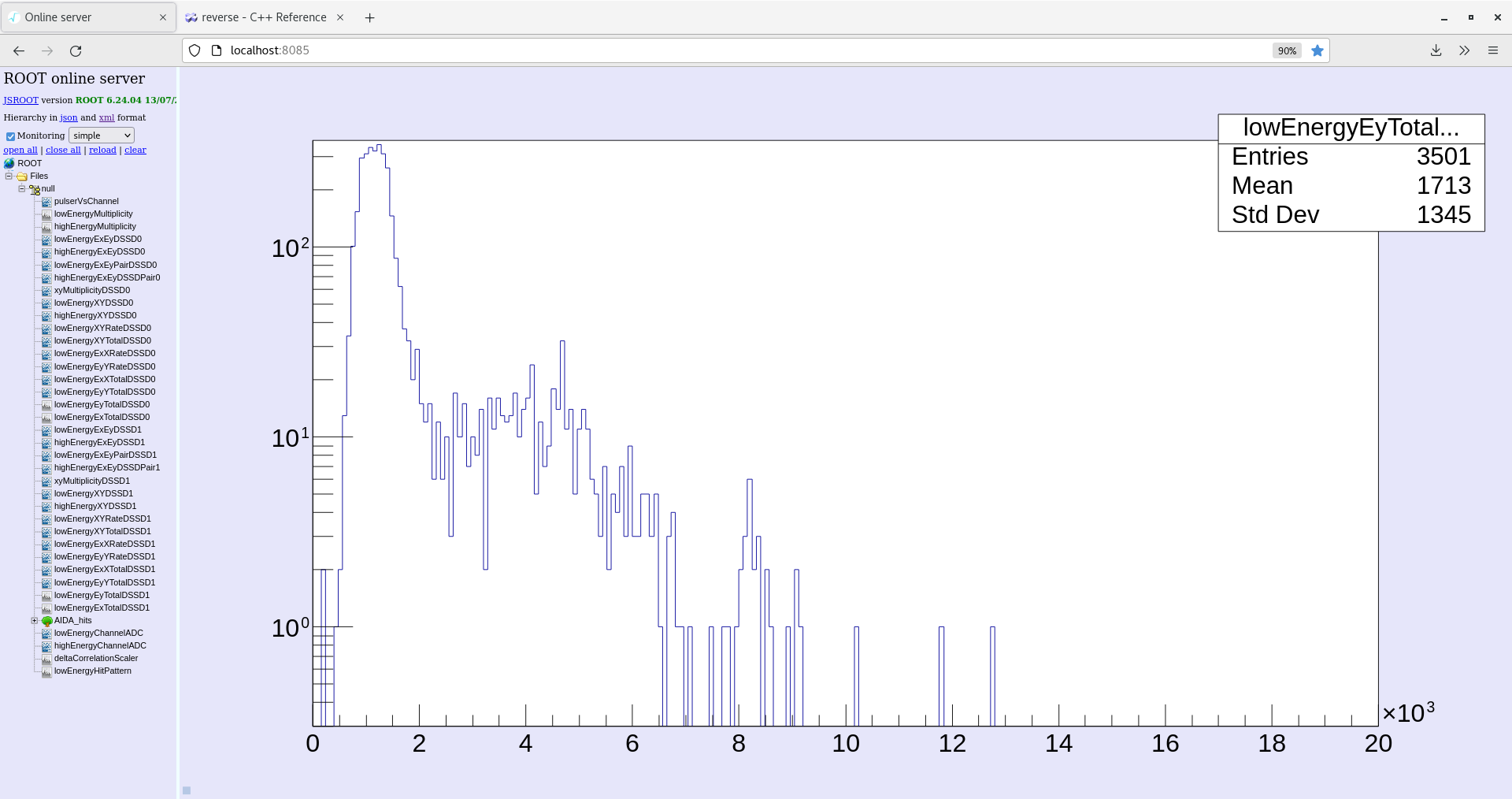
LowEnergyEyTotal (see attachment 8)
Check system wide checks tab: White Rabbit error counter test result: Passed 0, Failed 5 (see attachment 11) |
| Attachment 1: leakage_2022-02-17_13-58-44.png
|

|
| Attachment 2: data_item_2022-02-17_14-02-32.png
|

|
| Attachment 3: new-merger-2022-02-17_13-57-51.png
|

|
| Attachment 4: good_events_2022-02-17_14-01-53.png
|
|
| Attachment 5: temperature_2022-02-17_13-59-30.png
|

|
| Attachment 6: correlation_8_2022-02-17_14-01-13.png
|

|
| Attachment 7: energy_ex_total_2022-02-17_14-06-46.png
|

|
| Attachment 8: energy_ey_total_2022-02-17_14-08-06.png
|
|
| Attachment 9: energy-xy-total-2022-02-17_14-11-42.png
|

|
| Attachment 10: spectrum_browser_2022-02-17_14-03-27.png
|
|
| Attachment 11: system_wide_checks_2022-02-17_14-00-31.png
|

|
|
203
|
Thu Feb 17 08:31:07 2022 |
RSS, AG | Alpha background run43 |
09:15
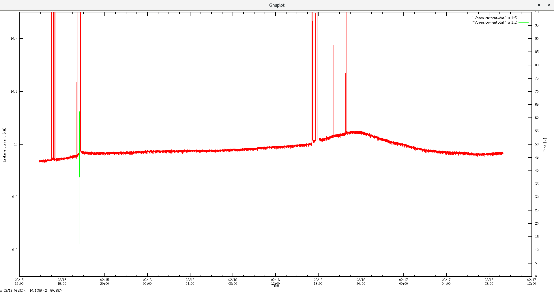
Check Leakage current: (see attachment 2)
Check NewMerger tab: (see attachment 5)
Check Fee temperatures: all green (see attachment 1)
Check statistics tab: ADC data items (see attachment 4)
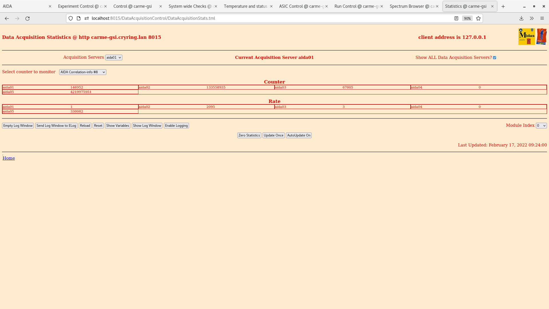
ADC coincidence-info #8 (see attachment 6)
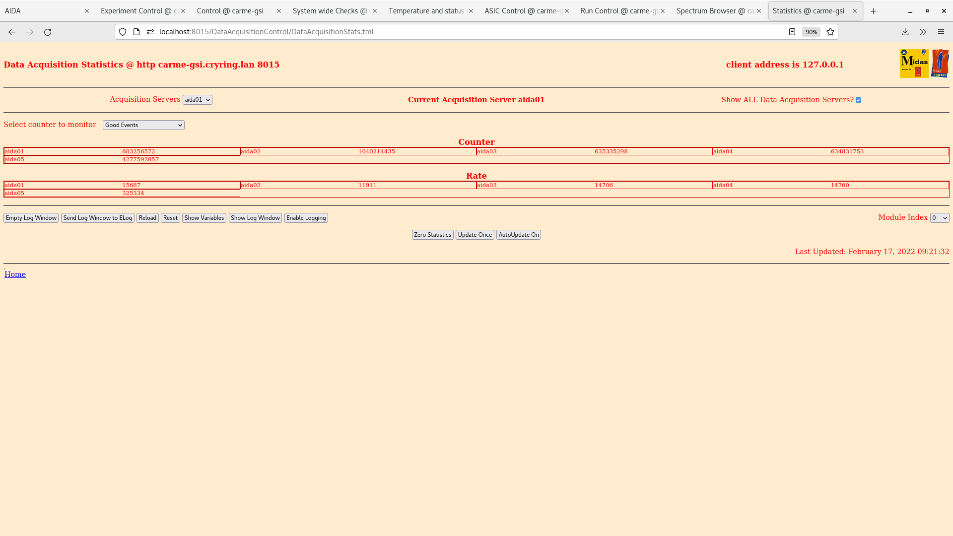
Good events (see attachment 7)
Check Spectrum Browser tab: (see attachment 10)
Check the following plots:
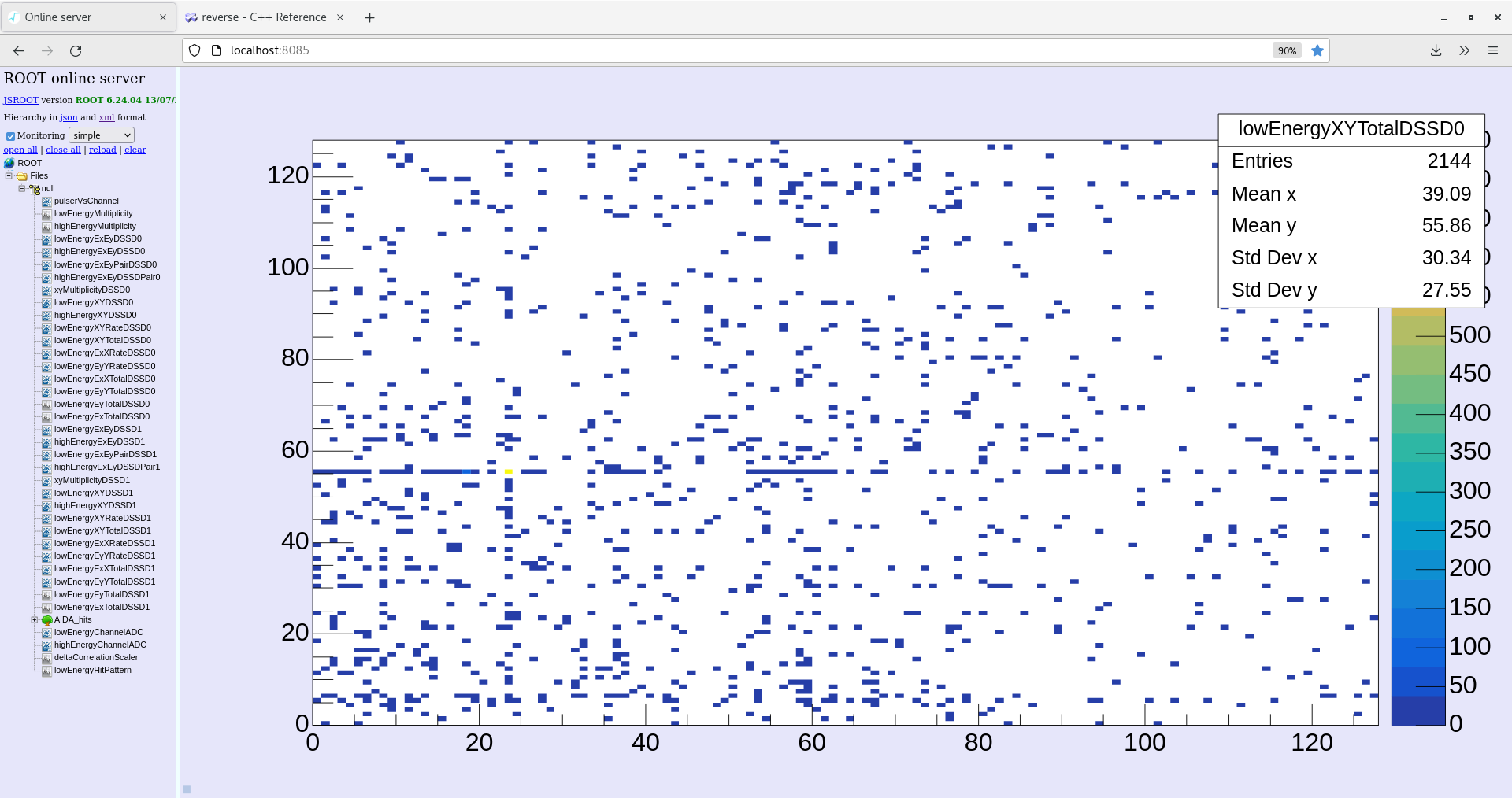
LowEnergyXYTotalDSSD0 (see attachment 3)
LowEnergyExTotal (see attachment 8)
LowEnergyEyTotal (see attachment 9)
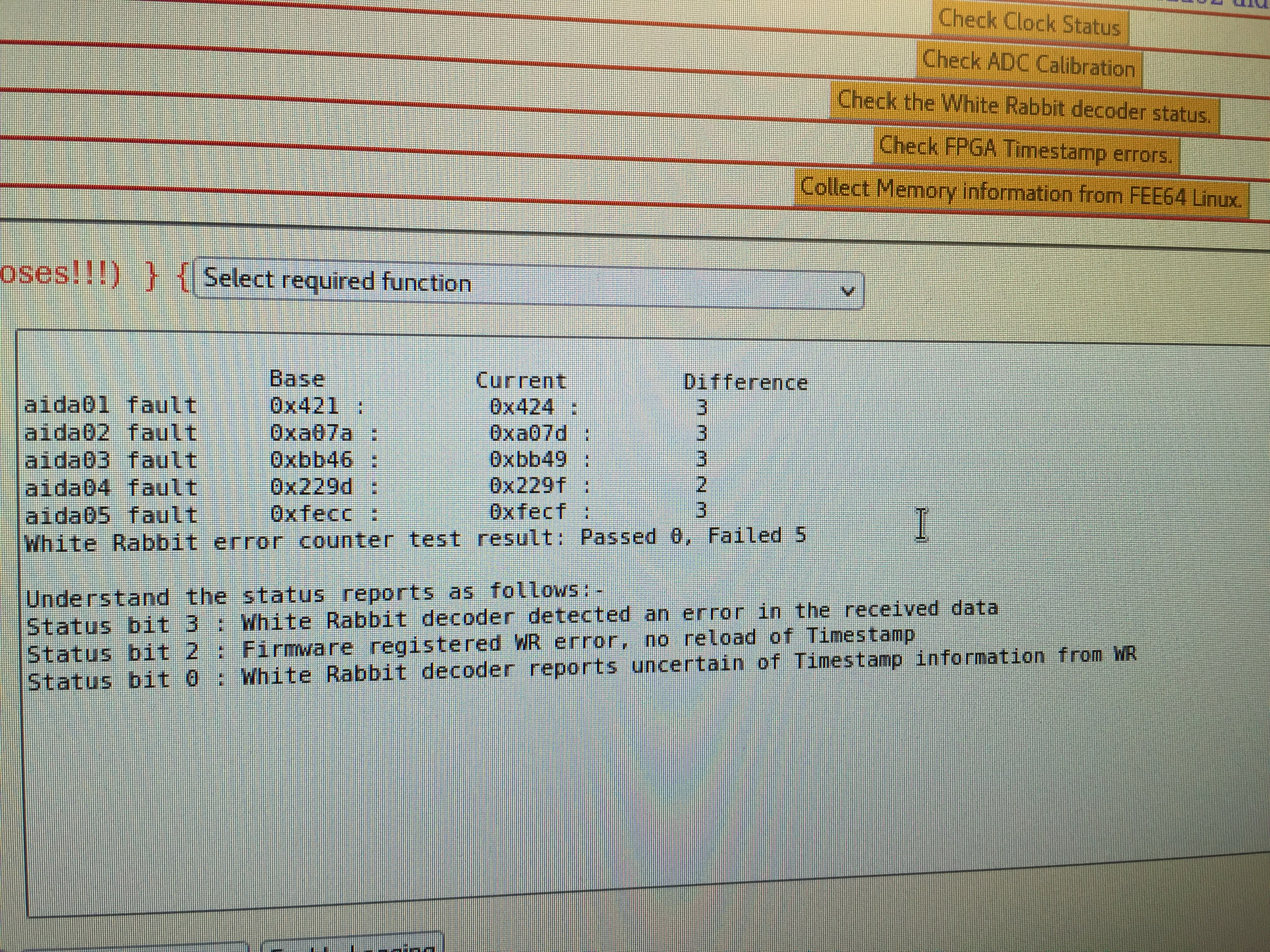
Check system wide checks tab: White Rabbit error counter test result: Passed 0, Failed 5 (see attachment 11)
|
| Attachment 1: temp-2022-02-17_09-16-02.png
|

|
| Attachment 2: leakage-2022-02-17_09-14-47.png
|
|
| Attachment 3: XY-Total-2022-02-17_09-30-30.png
|
|
| Attachment 4: data-items-2022-02-17_09-24-58.png
|

|
| Attachment 5: new-merger-2022-02-17_09-14-00.png
|

|
| Attachment 6: correlation-2022-02-17_09-24-05.png
|
|
| Attachment 7: good-events-2022-02-17_09-21-48.png
|
|
| Attachment 8: lowEnergy-Ex-2022-02-17_09-26-36.png
|

|
| Attachment 9: lowEnergy-Ey-2022-02-17_09-27-46.png
|

|
| Attachment 10: spectrum-browser-2022-02-17_09-25-45.png
|

|
| Attachment 11: IMG_6932.JPG
|
|