| ID |
Date |
Author |
Subject |
|
34
|
Fri Apr 13 08:24:47 2018 |
Thomas Chillery, Lucio Gialanella | Attempting to add downstream S2 to DAQ setup and fixing problems during setup |
Date: 07/04/2018 (Last day of April shift)
9:55 pressures read: CHUP = 1.3e-5 mBar, CHDW = 3.5 e-5 mBar
I noticed the preamp power (+/- 15V) was left on overnight. The +15V still draws 1.5A and -15V draws ~600mA as expected. During this shift no noticeable change in the currents drawn was observed.
We biased the detectors:
- Central S2 bias = -129,9V, leak I = 17.42 uA (Perhaps this has stabilised to a new value?)
- diode bias = -70.0V, leak I = 0.01uA
- Downstream S2 bias = -130.0V, leak I = 2.38 uA
We decided to adjust the RAL amplifier thresholds for the downstream S2, whilst looking at the analogue and timing outputs on an oscilloscope.
RAL I threshold increased from 15mV to 130mV.
We then struggled to see timing signals from the next 3 RALS in the rack (RAL II, RAL XI, and RAL IV).
The ribbon cables 8,9,10, and 11 connected between the RAL ECL outputs and the Lecroy MALU 4532 modules where tested using the working RAL I ECL output. It was discovered that cables 8 and 9 work, whereas cables 10 and 11 show no signals (note: cables 8,9,10, and 11 merge from 2X8 into 16 channels) . However, even if we plug the working cable 8A into RAL II, XI, or IV we see no OR signals on the oscilloscope, even with RAL threshold setting set to 15mV.
We decided that since this is the last day, and the central detector showed no problems yesterday afternoon, to only incorporate RAL I (first 8 channels on downstream S2) into the DAQ setup.
This problem with the downstream S2 cabling should be addressed at the very beginning of the next shifts, I suspect the problem lies with the vacuum feedthrough -> preamp cable. The cable was removed after the Feb 2018 shifts to add copper tape and its possible that out of the three we have one is damaged. The third (spare) cable is not yet wrapped in copper tape, this will be brought back to Edinburgh after these shifts to apply the tape.
The DAQ OR now comes from:
- RAL I (downstream S2)
- RAL X -> "W" (central S2)
- diode monitor
The analogue output of RAL 1 was sent to the first 8 channels of ADC 1 (module 2)
The RAL X -> "R" go to ADC 3 (module 4) via ribbon cables 12 and 13 and RAL "S" -> "W" go to ADC 4 (module 5) via ribbon cables 14 and 15
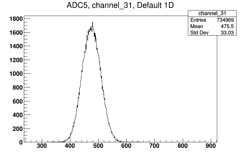
The diodes analogue output still goes to ADC 5 (module 6) channel 31, the same case as the Feb 2018 shift
We tried starting the DAQ with no beam, however it gave the error message: Timeout: Performing automatic clear
- After 5 minutes it did not clear, nor give the user control over the start/stop of the DAQ
- We logged into the FAIR console with username root and the password, then ran "reboot -ah" to reboot the FAIR DAQ machine located next to the electronics racks
- We then restarted the FAIR DAQ monitor in the control room
- After rebooting both machines we confirmed the FAIR DAQ machine was on with no error
- We logged back onto the FAIR DAQ monitor in the control room -> needed to use shift+7 to produce the & symbol for the password
- The DAQ is now working
Since we rebooted the DAQ we had to reset parameters for the ADCs:
- RTP (Rise Time Protection) was set to 9 for all ADCs
- The faulty ADC 2 (module 3) lower threshold was set to 2046 (out of 2047)
- The TDC lower threshold was also set to 2046 (out of 2047)
- ADC 1, 3, 4, and 5 (modules 2, 4, 5, and 6) lower thresholds set to 8
We started tuning the accelerator ready for a measurement. We decided to first tune using the 7Li beam from a 7LiO2 cathode, however we realised this was not recorded yesterday. The cathode used should always be recorded in the eLog from now on.
We set the cathode to position 9 - the second 7LiO2 option
Before tuning we:
- Closed the central iris (actuator setting = 85.5 mm)
- Closed the downstream iris (actuator setting = 82.5 mm)
- Set target ladder to position I (95.010mm) - the 3mm collimator
- Opened the line valve
- Decreased the pulser rate from 10 to 2 Hz
With no beam the DAQ reads:
- DT = 0%
- Trigger rate = 25Hz
- Event mult = 72.6
After tuning, including adjusting the steering magnet, faraday cups read:
- FC - 4 = 50 pA
- FC - 0 = 23 pA
- FC - E1 = 16 pA --> 70% transmission
The High Energy slits were left at 1mm for the Up, Down, Right, and Left
We then prepared for the target measurement by:
- Opening the central iris (Actuator = 14.0mm)
- Opening the downstream iris (Actuator = 1.5mm)
- Target ladder set to position IV (50.015mm) - CH2 Target III
- Lowering the pulse height from 1.0 to 0.5 V to lower it to ~ the center of the ADC front strips spectra
We tried running 7Li beam on target, but saw a very low trigger rate in the DAQ of ~ 20Hz. We stopped the beam and Lucio tried increasing current by increasing the Source Heater temperature to ~ 81 degrees centigrade.
At 12:09 FC - 4 = 100pA. We decided to run some 7Li beam whilst the source was heating up -> it will need to run hotter for 7Be anyway. |
|
16
|
Thu Feb 22 14:55:09 2018 |
Thomas Chillery | ADC6 Settings |
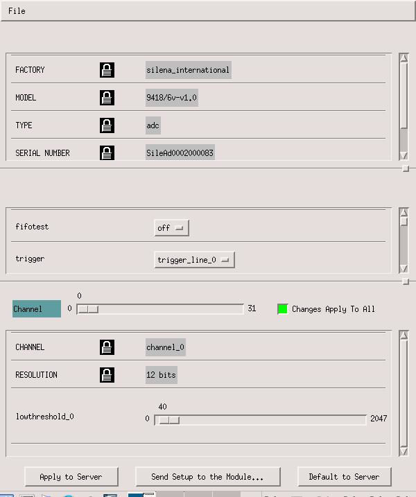
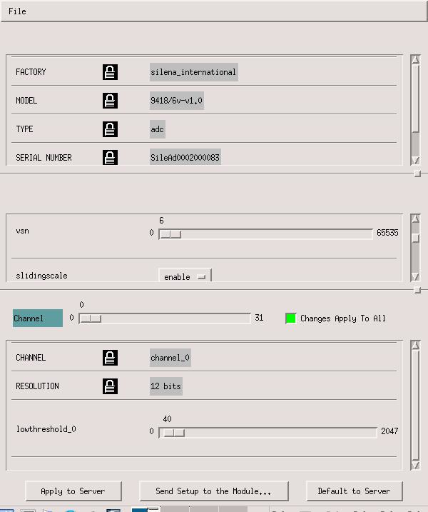
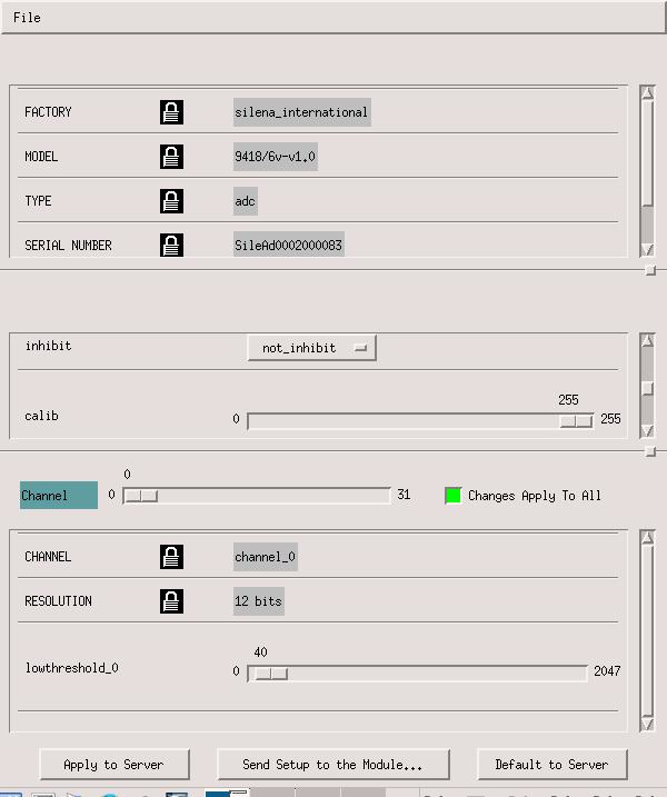
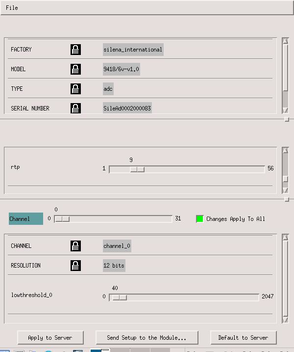
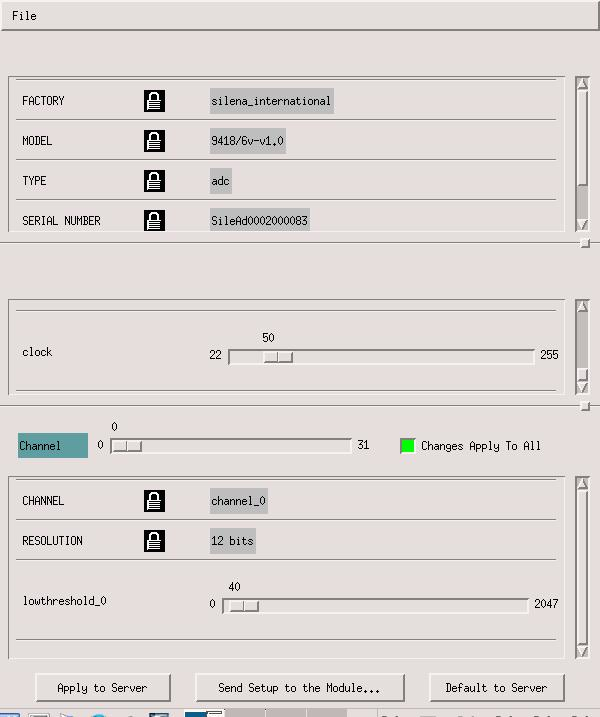
DAQ Settings for ADC6 settings attached. ADC 6 has been used for the pin diode during the week starting 19/02/2018 |
| Attachment 1: ADC6_Settings1.jpg
|
|
| Attachment 2: ADC6_Settings2.jpg
|
|
| Attachment 3: ADC6_Settings3.jpg
|
|
| Attachment 4: ADC6_Settings4.jpg
|
|
| Attachment 5: ADC6_Settings5.jpg
|
|
|
57
|
Mon Dec 3 11:54:55 2018 |
Thomas Chillery, Carlo Bruno, Tom Davinson, Raffaele Buompane | 7Li 6.0 MeV on CH2 XVI and XVIII, and on natC III |
On 25/11/2018:
At 8:45 the pressures read (mBar):
- TPU1 = 1.0e-6
- TPU2 = 3.2e-7
- TPD1 = 6.5e-7
- TPD2 = 6.1e-7
- CHUP = Sensor Off
- CHDW = No Sensor
Biased detectors: Far S2 bias = -130.0V, leak I = 1.80uA. Diode bias = -70.1V, leak I = 0.00uA.
Checked pulser frequency:
- Frequency setting = 25Hz (250Hz max fine gain setting)
- Pulser frequency measured internally by scope: 19.29->19.31Hz
- Pulser frequency measured using cursors on scope: 19.38Hz
Target ladder left in position #2 overnight - 10mm aperture. Far S2 iris also left open overnight.
Checked for beam induced background from beam scattering on aluminium target frame and/or ladder. FC4 ~ 17pA, FCC ~ 6pA
Run # 181125090005
- Run time: 977s
- Pulser ON, as before
- Target: 10mm aperture
- Beam: 4.0MeV 7Be 2+
Tuned beam for 6.0MeV 7Li 2+
After tuning: FC4 = 1.05nA. Using 10mm aperture FCC = 520pA, using 3mm aperture FCC = 460-480pA.
Collected 7Li + p data using old target CH2 XVI (used for 7Be yesterday)
Run # 181125112005
- Run time: 754s
- Pulser ON, as before
- Target: CH2 XVI
- Beam: 6.0MeV 7Li 2+
- DT ~ 10%
Run # 181125113257
- Run time: 18s
- Pulser ON, as before
- Target: CH2 XVI
- Beam: 6.0MeV 7Li 2+
Moved target ladder to position # 4 - fresh CH2 XVIII
Run # 181125113734
- Run time: 324s
- Pulser ON, as before
- Target: CH2 XVIII
- Beam: 6.0MeV 7Li 2+
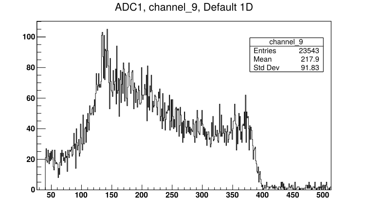
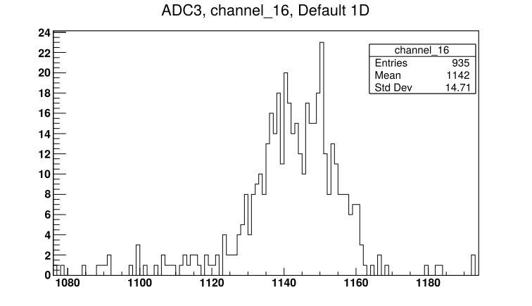
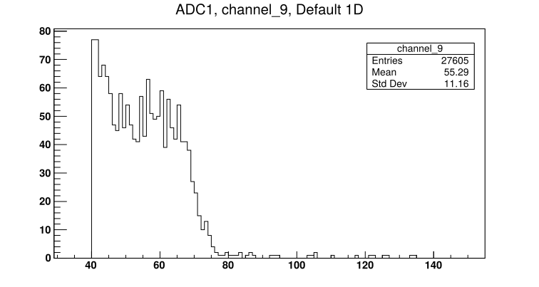
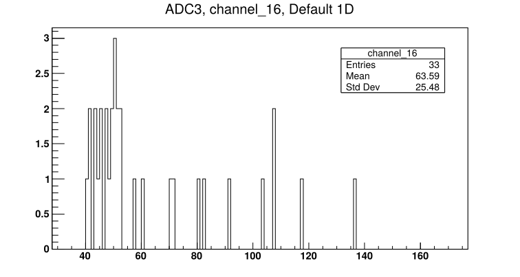
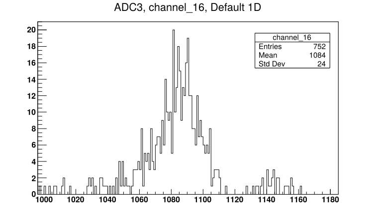
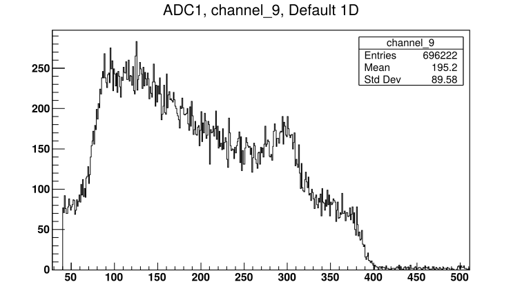
See attached picture 1 for a sample spectrum from one of the Far S2 front strips. See attached picture 2 for the diode spectrum.
Moved target ladder to position #5 - natC III
Run # 181125114513
- Run time: 620s
- Pulser ON, as before
- Target: natC III
- Beam: 6.0MeV 7Li 2+
After the previous run, it was discovered the pulser was still being split between the far S2 preamp test input, and the oscilloscope (morning check of pulser frequency). Therefore the pulser had an additional load and we expect a shift in the pulser amplitude compared to runs made yesterday.
Checking for beam induced background, the target ladder was moved to position #2 - blank 10mm aperture
Run # 181125115810
- Run time: 386s
- Pulser ON, as before
- Target: Blank 10mm aluminium frame
- DT ~ 8%
- FCC ~ 400pA
|
| Attachment 1: 181125113734_ADC1_Ch9.png
|
|
| Attachment 2: 181125113734_ADC3_Ch16.png
|
|
|
32
|
Thu Apr 12 13:12:00 2018 |
Thomas Chillery, Raffaele Buompane | 7Li 5.0MeV Beam tests with Central S2 |
Date: 06/04/2018 (after 16:40)
We powered the preamps for the two S2 detectors and the diode.
We biased the detectors:
- Downstream S2 bias = -130.1V, leak I = 2.18uA
- Central S2 bias = -129.9V, leak I =16.71 uA
- diode bias = -70.1V, leak I = 0.01uA
The target ladder was set to position II (No target/frame).The downstream iris was closed to 18mm diameter (actuator setting = 82.5mm). The central iris was closed to 18mm diameter (actuator setting = 85.5mm)
We were ready to begin beam tuning with 7Li.
With no beam, DAQ DT = 2%, trigger rate ~ 800Hz, event mult = 3.6. The DAQ OR is from the central S2 and diode.
During the tuning we had a problem with the CSSM valve -> this is needed to operate the CSSM ERNA magnet for bending the beam into the electron suppressed Faraday cup FC-E1, located downstream from the chamber.
Raffaele fixed this by using an older version of the CSSM magnet labview software.
During tuning we cut the beam using the High Energy slits, the final slit positions were 1mm for the Up, Down, Right, and Left
After tuning with no target frame in the beam axis, we had: FC-4 = 138 pA and FC-E1 = 120 pA, Total transmission = 87%
We set the target ladder to position IV, target CH2 III. The central iris was opened (central actuator = 14.0mm).
At 17:50 we started the DAQ for 5.0MeV 7Li 2+ on target CH2 III. The beam current on FC-0 (immediately before chamber) was 118 pA.
- DT = 18%
- Save name: 180406165546
We saw no signal on the diode monitor, however we saw signals on the central S2, during this run we were adjusting the diode monitor CFD threshold to try and see coincidences with the diodes delayed analogue output on an oscilloscope. So this run is invalid for the diode spectrum,
At 18:40 the DAQ was stopped, run time = 00:47:16
We decided to try adjusting the diode analogue gain on the Ortec 571 amplifier
At 18:40 we restarted the DAQ, again for 5.0MeV 7Li on target CH2 III
- Save name: RData_1/180406174522
- In February 2018 the diode course gain = 50, which corresponded to channel 1000 when no mylar was placed in front of the diode. Now we have 0.9um thick (nominal) mylar in front of the diode.
- During this run we increased the course gain of Ortec 571 to 200
- The delay amplifier was adjusted from 1us to 1.5us, however we saw no difference in the diode spectrum, so this was set back to its original value of 1us
We decided to change over to 7Be beam |
|
35
|
Fri Apr 13 13:59:18 2018 |
Thomas Chillery, Lucio Gialanella | 7Li 5.0MeV Beam test with Central S2 and Downstream S2 first 8 channels |
Date: 07/04/2018
At 12:10 we started the DAQ for 5.0 MeV 7Li in 2+ charge state bombarding CH2 Target III
- Save name: RData_1/180407111531
- DT = 0%
- Trigger rate ~ 30 Hz
- Event mult = 77.5
At 12:31 we briefly stopped the beam to check the beam current, FC - 4 = 200 pA
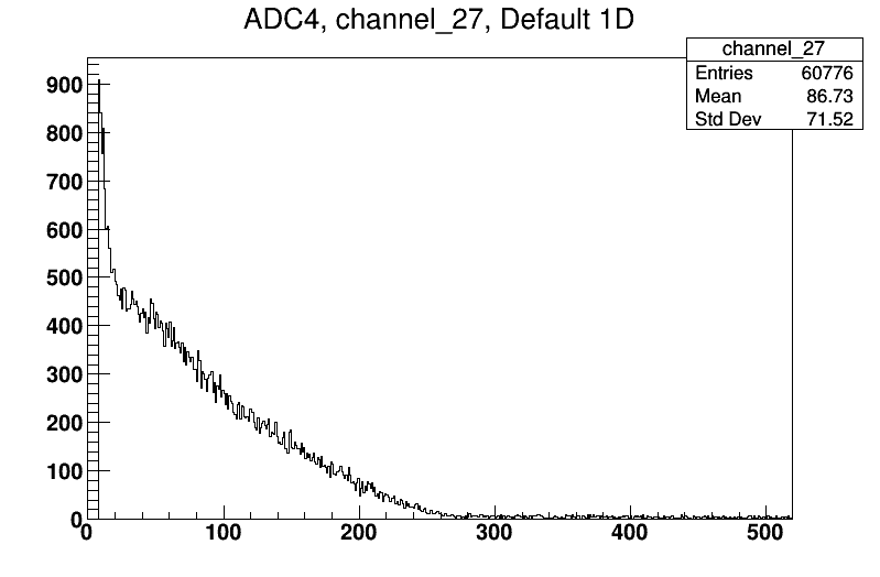
At 13:30 we stopped data aquisition, # good events = 735088. See attached for example spectra of the Central S2 front and back strips, downstream S2 front strips, and the diode monitor.
At 13:32 the pressures read:
- TPU1 = 2.1e-6 mBar
- TPU2 = 9.0e-7 mBar
- TPD1 = 1.4e-6 mBar
- TPD2 = 1.7e-6 mBar
- CHUP = 1.1e-5 mBar
- CHDW = 1.3e-5 mBar
The detectors status:
- Central S2 bias = -129.9V, leak I = 17.90uA
- diode bias = -70.1V, leak I = 0.00uA
- Downstream bias = -130.0V, leak I = 2.59uA
|
| Attachment 1: 180407_7Li_5MeV_CentralS2_FrontStrip.png
|

|
| Attachment 2: 180407_7Li_5MeV_DWS2_FrontStrip.png
|

|
| Attachment 3: 180407_7Li_5MeV_CentralS2_BackStrip.png
|
|
| Attachment 4: 180407_7Li_5MeV_Diode.png
|
|
|
54
|
Mon Nov 26 17:10:13 2018 |
Thomas Chillery, Marialuisa Aliotta, Carlo Bruno, Tom Davinson, Raffaele Buompane | 7Li 4.0 MeV beam on natC target 3 |
On 23/11/2018:
After the runs with 7Li on CH2 15, we moved the target ladder to position 5: carbon foil #3 (~590 ug/cm^2)
Run # 181123214406
- Run time: 1247
- Pulser ON, same settings as run # 181123130304
Beam intensity = 150pA on FCC with 3mm aperture
For the night we closed the quadrupole and line valves, and switched off the pumps and detectors. |
|
53
|
Sat Nov 24 16:39:22 2018 |
Thomas Chillery, Marialuisa Aliotta, Carlo Bruno, Tom Davinson, Raffaele Buompane | 7Li 4.0 MeV beam on CH2 target 15 |
On 23/11/2018:
Tuned beam for 4.0 MeV 7Li, charge state 2+
Measured transmission of beam through FCC using 3 mm and 10 mm size collimators: 66 pA with 10 mm -> 60 pA with 3 mm -> 91% transmission
FC4 = (330 - 263) pA = 127 pA
Set target ladder to position 3 - CH2 target 15 (880 +/- 40 ug/cm^2)
Start run
- Run # 181123130304
- Pulser: 70000 amplitude, x10 attenuation, 25Hz frequency (250Hz minimum fine setting), positive polarity
- Run time ~30 minutes
Start run
- Run # 181123134943
- Pulser: as above
- Run time 588 seconds
Moved to position #2 on target ladder, 10mm collimator. Increasing beam intensity -> have to refocus
Moved ladder to position #1 (3mm collimator). Closed iris. Refocusing.
Beam intensity after refocus: ~140pA with 10mm, ~90pA with 3mm. Trigger rate ~ 5500 counts/s
Moved ladder to position #3: CH2 target 15
Run # 181123142805
- Pulser: as above
- Run time: 1034
We found high rates on ADC 1 -> swapped input cables between ADC 1 and ADC 2 (modules #2 and #3)
Run # 181123144810
- Run time: 417
- Pulser: as above
Set RAL thresholds to 20mV for first 8 modules
Run # 181123150803
- Run time: 398
- Pulser: as above
Did not help with ADC 1 counting less than ADC 2. Swapping ADC 1 with ADC 4.
Run # 181123151711
- Run time: 324
- Pulser: as above
Swapping back ADC 4 -> ADC 1. Found ECL cable between the MALU module corresponding to ADC 1 and OR not plugged in. Trigger rate now 44000. Re-optimising noise.
RAL first 6 modules thresholds set to 30 mV. DT ~ 44%, high trigger rate.
First 3 RAL thresholds set to 35 mV, next 3 RAL thresholds set to 20 mV. Preamp box lid removed.
Run # 181123162236
Run # 181123163138
- Run time: 1561
- Pulser: ON, rate: 2.5 Hz, other settings unchanged
Run # 181123165817
- Run time: 3731
- Pulser as previous run
Run # 181123180118
- Run time: 1971
- Pulser ON, as before
Run # 181123183556
- Run time: 1638
- Pulser ON, as before
Checking beam intensity:
- Beam intensity = 197pA in FC4 at 18:34
- Beam intensity = 100 pA (91->105 pA) in FCC at 19:00
Run # 181123191153
- Run time: 7029
- Pulser ON, as before
Checking beam intensity:
- Beam current = 167 pA in FC4 at 21:00
- Beam current = 83 pA in FCC at 21:00
Lowering RAL thresholds:
- RAL #1 and 2 thresholds set to 25mV
- RAL #3 threshold set to 20mV
- RAL #4, 5, and 6 thresholds unchanged at 20mV
Now trigger rate ~ 5kHz, dead time ~ 8 - 10%
Run # 181123212726
- Run time: 807
- Pulser ON, as before
- Target: CH2 XV
- RAL #3 threshold increased to 25mV during this run
After previous run (# 181123212726) pulser frequency setting set to 25Hz, other settings unchanged |
|
33
|
Thu Apr 12 14:14:09 2018 |
Thomas Chillery, Raffaele Buompane | 7Be 5.0MeV Beam test with central S2 |
Date: 06/04/2018
Before starting this beam test we lowered the channel thresholds on ADC 3 and 4 (modules 4 and 5) from 40 to 8
The diode Ortec 571 settings are:
- Fine gain = MAX
- Course gain = 200
- Shaping Time = 0.5us
The diode Delay Amp 1457 settings are:
- Delay = 1us
- Polarity = POS
- Range = 10V
The diode quad CFD (channel 4) threshold = 196 mV
The PB-5 Pulse Generator settings are:
- Fall Time = 100us
- Rate = 10Hz
- Delay = 250 ns
- Ampl = 1V
- Pol = POS
- Pulse Top = Tail
- Atten = 1X
- Clamp = OFF
(Make sure PB-5 = ON to output pulses)
At 19:14 we started the DAQ for 5.0 MeV 7Be at charge state 2+ on target CH2 III
- Dead time = 5%
- Trigger rate ~ 1.8kHz
- Event mult ~ 22.1
- Save name = RData_1/180406181929
At 19:30 we stopped the DAQ, Real time = 00:15:53, dead time = 5%, # good events = 1936195
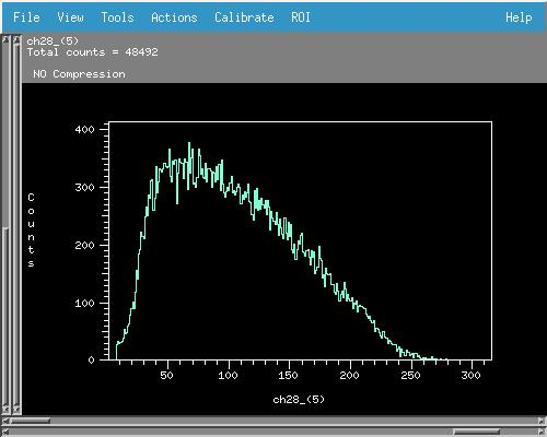
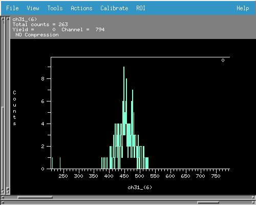
See attached images for an example back strip and front strip of the central S2, and also for the diode spectrum
Before finishing for the day we decided to once again try to incorporate the downstream S2 into the DAQ setup, because this should have better angular resolution than the central S2
We opened the downstream iris (actuator setting = 1.5mm)
We plugged in RAL I, II, XI, and IV into ADC 1 (module 2) channels 0 ->31, these are the first 32 channels of the downstream S2 preamp output
Even with no beam the DAQ DT = 92% with event mult = 52.0 --> still have a noise problem with the downstream S2
At 19:41 the pressures read:
- TPU1 = 3.3e-6 mBar
- TPU2 = 9.6e-7 mBar
- TPD1 = 1.5e-6 mBar
- TPD2 = 1.7e-6 mBar
- CHUP = 1.0e-5 mBar
- CHDW = 2.7e-5 mBar
The detector biases were:
- Central S2 bias = -129.9V, leak I = 18.39 uA
- diode bias = -70.1V, leak I = 0.00uA
- Downstream S2 bias = -130.1V, leak I = 2.78uA
We called it a day and at 19:45 the detectors were switched off and the line valve closed for the night |
| Attachment 1: 180406_7Be_5MeV_CentralS2_BackStrip.jpg
|
|
| Attachment 2: 180406_7Be_5MeV_Diode.jpg
|
|
| Attachment 3: 180406_7Be_5MeV_CentralS2_FrontStrip.jpg
|

|
|
38
|
Fri Apr 13 14:56:11 2018 |
Thomas Chillery, Lucio Gialanella | 7Be 5.0MeV Beam test on CH2 target IV with central S2 and downstream S2 channels 0-7 |
Date: 07/04/2018
FC - 4 = 410 - 260 = 150 pA
We moved the target ladder to position V (35.022mm) - CH2 Target IV
At 15:09 we started the DAQ for 5.0 MeV 7Be in 2+ charge state bombarding CH2 IV
- DT = 0%
- Trigger rate ~ 10Hz
- Event mult = 69.7
- Save name recorded on paper logbook as 180407111531 -> same as save name used for 7Li -> emailed Raffaele to check whether there are other saves starting with 180407......
At 16:39 the DAQ was stopped, RT = 01:29:07, # good events = 68068
Checked beam current due to low trigger rate, FC-4 = 405 - 260 = 155 pA
Central and downstream irises closed, target ladder set to position VII - 3mm collimator
FC - E1 = 63 - 5 = 58 pA, Transmission ~ 33%
Stopped beam, Time ~ 17:00, decided to stop and dismount detectors
17:00 pressures read:
- TPU1 = 2.2e-6 mBar
- TPU2 = 8.2e-7 mBar
- TPD1 = 1.3e-6 mBar
- TPD2 = 1.5e-6 mBar
- CHUP = 1.0e-5 mBar
- CHDW = 2.7e-5 mBar
Detector status:
- Central S2 bias = -129.9V, leak I = 18.71uA
- diode bias = -70.1V, leak I = 0.00uA
- Downstream S2 bias = -130.1V, leak I = 2.84uA
|
|
37
|
Fri Apr 13 14:42:31 2018 |
Thomas Chillery, Lucio Gialanella | 7Be 5.0MeV Beam test on CH2 target III with central S2 and downstream S2 channels 0-7 |
Date: 07/04/2018
To run the measurement we:
- Opened the central iris (actuator setting = 14.0mm)
- Opened the downstream iris (actuator setting = 1.5mm)
- Set the target ladder to position IV (50.015mm)- CH2 Target III
At 14:40 we started the DAQ for 5.0MeV 7Be in the 2+ charge state on CH2 Target III
- DT = 0%
- Trigger rate ~ 10Hz
- Event mult = 71.2
- Save name: 180407134535
At 15:04 we stopped the DAQ
- The proton spectrum seems very thin
- Decided to change to fresh CH2 target IV
|
|
56
|
Mon Dec 3 11:28:53 2018 |
Thomas Chillery, Carlo Bruno, Tom Davinson, Lucio Gialanella, Antonino d'Leva | 7Be 4.0MeV on CH2 XVI and natC III |
On 24/11/2018:
After the short test with 4.0MeV 7Li (see eLog #55) the beam was tuned for 4.0MeV 7Be 2+.
Run # 181124103943
- Run time: 43s
- Target: CH2 XVI
- Beam: 4.0MeV 7Be 2+
- Comment: Far S2 iris was closed!
Run # 181124104408
- Run time: 3971s
- Pulser ON, as before
- Target: CH2 XVI
- Beam: 4.0MeV 7Be 2+
After this run we checked the beam current:
FC4 = 10pA
Using 10mm aperture FCC = 4.5pA, using 3mm aperture FCC = 4.0pA
Attempted to increase beam current by adjusting bending magnet - optimum: 413.30mT
Run # 181124120558
- Run time 7930s
- Pulser ON, as before
- Target: CH2 XVI
- Beam: 4.0MeV 7Be 2+
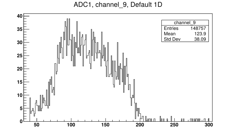
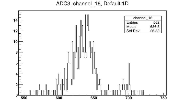
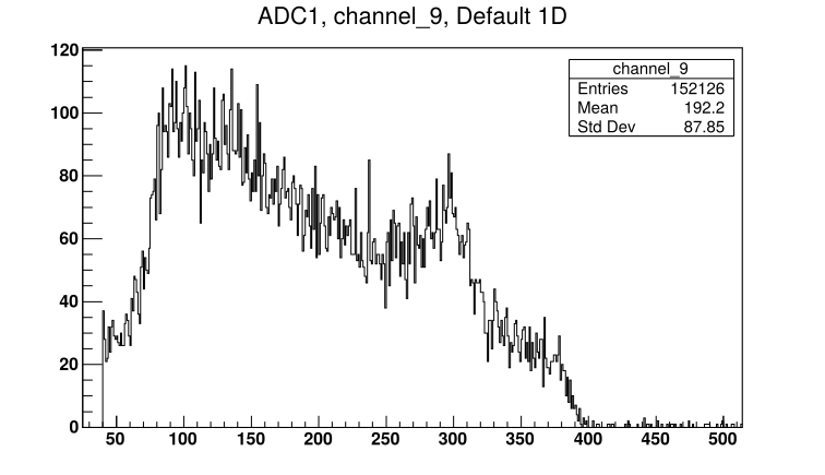
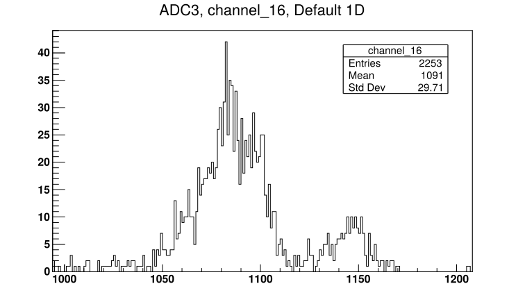
See attached picture 1 for a sample spectrum from the S2 front strip. See attached picture 2 for the diode spectrum - the peaks from 7Be and 7Li are visible. Recall the diode has a 0.9um mylar protective foil in front of it.
Run # 181124141834
- Run time: 3362s
- Pulser ON, as before
- Target: CH2 XVI
- Beam: 4.0MeV 7Be 2+
Further attempts to increase beam current, ioniser increased from 24.0 -> 24.5A. FC4 = 15pA
Run # 181124154345
- Run time: 3609s
- Pulser ON, as before
- Target: CH2 XVI
- Beam: 4.0MeV 7Be 2+
Checked beam current: using 10mm aperture FCC = 4pA (time: 16:44)
Decreased oven temperature -> FC4 = 16pA
Run # 181124165221
- Run time: 4221s
- Pulser ON, as before
- Target: CH2 XVI
- Beam: 4.0MeV 7Be 2+
Collected background using carbon target:
Run # 181124180623
- Run time: 463s
- Pulser ON, as before
- Target: natC III
- Beam: 4.0MeV 7Be 2+
Beam current seemed unstable, run stopped, no actions taken. FCC ~ 5pA.
Run # 181124182304
- Run time: 3647s
- Pulser ON, as before
- Target: natC III
- Beam: 4.0MeV 7Be 2+
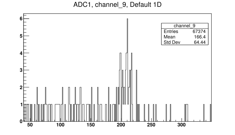
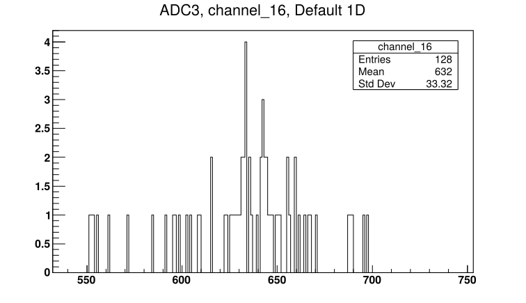
See attached picture 3 for a sample spectrum from the S2 front strip. The spectrum indicates hydrogen contamination is present on the carbon foil. See attached picture 4 for the diode spectrum.
After run: checked beam current. FC4 = 18pA. Using 10mm aperture FCC = 5.5pA.
Leaving for the night:
Far S2 leak I = 1.87uA. Far S2 and diode biases off.
19:25 pressures (mBar):
- TPU1 = 1.4e-6
- TPU2 = 3.7e-7
- TPD1 = 7.0e-7
- TPD2 = 6.6e-7
- CHUP = Sensor Off
- CHDW = No Sensor
|
| Attachment 1: 181124120558_ADC1_Ch9.png
|
|
| Attachment 2: 181124120558_ADC3_Ch16.png
|
|
| Attachment 3: 181124182304_ADC1_Ch9.png
|
|
| Attachment 4: 181124182304_ADC3_Ch16.png
|
|
|
64
|
Mon Dec 3 17:02:48 2018 |
Thomas Chillery, Carlo Bruno, Lizeth Morales, Guiseppe Porzio, Raffaele Buompane | 6Li(p,p): Tuning 1.5MeV 6Li 1+ beam |
On 27/11/2018:
Started tuning for 1.5MeV 6Li 1+. Set ladder to position #2 - Blank 10mm. Far S2 iris closed.
Run # 181127151653
- Run time: N/A
- Pulser ON, as before
- Target: Blank 10mm
- Beam: 1.5MeV 6Li 1+
Moved ladder to position #5 - natC III
Run # 181127152055
- Run time: N/A
- Pulser ON, as before
- Target: natC III
- Beam: 1.5MeV 6Li 1+
- DAQ Crashed
Restarted FAIR DAQ
Run # 181127153422
- Run time: N/A
- Pulser ON, as before
- Target: natC III
- Beam: 1.5MeV 6Li 1+
- Run stopped incorrectly by user
Run # 181127153506
- Run time: 489s
- Pulser ON, as before
- Target: natC III
- Beam: 1.5MeV 6Li 1+
Run # 181127155040
- Run time: 187s
- Pulser ON, as above
- Target: natC III
- Beam: 1.5MeV 6Li 1+
Moved ladder to position #3 - CH2 XVI
Run # 181127155607
- Run time: 908s
- Pulser ON, as above
- Target: CH2 XVI
- Beam: 1.5MeV 6Li 1+
- DT ~ 15%
Struggling to see beam in diode for all of these past runs.
Opened iris to use far S2 as diagnostic tool - beam is stopped in thick CH2 targets so detector is safe even at its small angular coverage (~5 - 15 degrees)
Run # 181127161508
- Run time: 14s
- Pulser ON, as before
- Target: CH2 XVI
- Beam: 1.5MeV 6Li 1+
No high rate seen
Run # 181127161656
- Run time: 194s
- Pulser ON, as before
- Target: CH2 XVI
- Beam: 1.5MeV 6Li 1+
- DT ~ 12%
Still struggling to see beam on diode
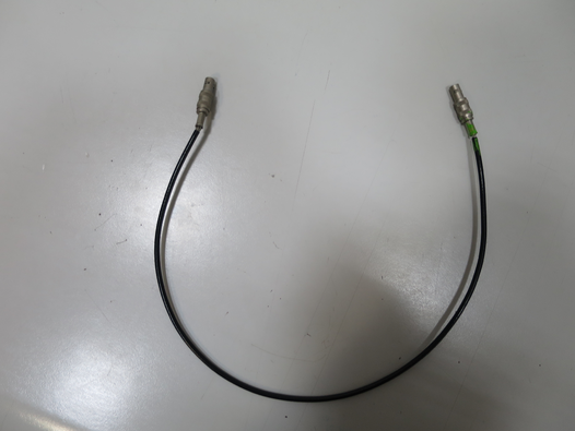
Found lemo cable used for diode timing between CFD and Logic OR has exposed cabling -> replaced lemo. See attached picture 1 for old lemo.
Run # 181127163416
- Run time: 106s
- Pulser ON, as before
- Target: CH2 XVI
- Beam: 1.5MeV 6Li 1+
Far iris opened
Run # 181127163848
- Run time: N/A
- Pulser ON, as before
- Target: CH2 XVI
- Beam: 1.5MeV 6Li 1+
Realised we were making a mistake when looking at the DAQ spectra. We were looking at ADC 2 (labelled as 3 on DAQ file browser) channel 16 (an S2 back strip) when we should have been looking at ADC 3 (labelled as 4 on DAQ browser) channel 16 for the diode
Closed iris, checked beam current. Using 10mm aperture FCC = 1pA.
Opened iris, moved ladder to position #3 - CH2 XVI
Run # 181127164749
- Run time: 556s
- Pulser ON as before
- Target: CH2 XVI
- Beam: 1.5MeV 6Li 1+
Ready to mount thin CH2 target.
At 16:55: Far S2 bias = -130.0V, leak I = 1.75uA. Diode bias = -70.1V, leak I = 0.00uA.
Pressures (mBar):
- TPU1 = 9,2e-7
- TPU2 = 3.4e-7
- TPD1 = 6.4e-7
- TPD2 = 6.8e-7
- CHUP = Sensor Off
- CHDW = No Sensor
Switched off detector biases, switched off preamps. Closed FCC valve. Closed line valve. Turbos off. T1600 backing and manual valves closed. Ecodry 1 and 2 off.
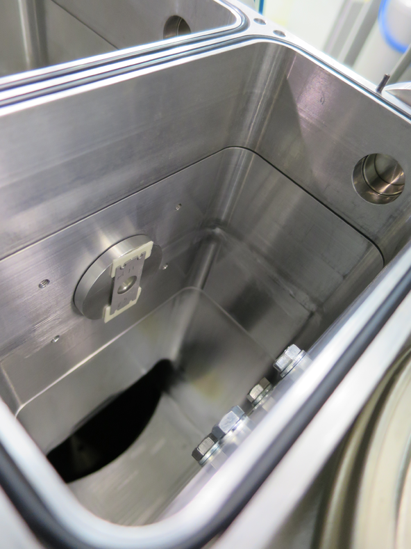
Vented chamber. Mounted thin target CH2 50 ~ 50mm from Far S2 - see attached picture 2.
Left 0.9um mylar in front of far S2.
Remounted far S2 and far preamp. With detectors on in air trigger rate ~ 9kHz.
19:00 Ecodry 1 and 2 on. Started opening manual valve.
19:15 pressures below 10 mBar, manual valve fully opened. T1600 backing valve opened. Turbos on.
19:25 Pressures (mBar):
- TPU1 = 3.2e-5
- TPU2 = 8.1e-6
- TPD1 = 6.0e-6
- TPD2 = 8.3e-6
- CHUP = Sensor Off
- CHDW = No Sensor
Far S2 biased to - 130.0V, leak I = 1.52uA. Diode biased to -70.1V, leak I = 0.00uA.
Closed iris, set ladder to position #2 - blank 10mm
See 1 -> 2 pA beam on FCC, opened iris ready for measurement. |
| Attachment 1: IMG_3285.JPG
|
|
| Attachment 2: IMG_3292.JPG
|
|
|
65
|
Mon Dec 3 17:34:38 2018 |
Thomas Chillery, Carlo Bruno, Raffaele Buompane | 6Li(p,p): Test measurement of 1.5MeV 6Li 1+ on thin CH2 50 |
On 27/11/2018:
After tuning beam (see previous eLog entry # 64)
Run #181127193908
- Run time: 1589s
- Pulser ON, as before
- Target: CH2 50
- Beam: 1.5MeV 6Li 1+
- See attached picture 1 for sample S2 front strip spectrum. See attached picture 2 for diode spectrum
|
| Attachment 1: 181127193908_ADC1_Ch9.png
|
|
| Attachment 2: 181127193908_ADC3_Ch16.png
|
|
|
58
|
Mon Dec 3 12:32:54 2018 |
Thomas Chillery, Carlo Bruno, Tom Davinson, Lucio Gialanella, Raffaele Buompane | 6.0MeV 7Be on CH2 XVIII |
On 25/11/2018:
The beam was tuned for 6.0MeV 7Be 2+
Using 10mm aperture FCC = 12 pA
Run # 181125121226
- Run time: 7264s
- Pulser ON, as before
- Target: CH2 XVIII
- Beam: 6.0MeV 7Be 2+
- See attached picture 1 for sample spectrum of Far S2 front strip. See attached picture 2 for diode spectrum.
Run # 181125141350
- Run time: 1887s
- Pulser ON, as before
- Target: CH2 XVIII
- Beam: 6.0MeV 7Be 2+
During this run at 14:40 there was a very brief power outage. The run was stopped afterwards.
Check chamber setup:
Far S2 bias = -130.0V, leak I = 1.89uA
Diode bias = -70.1V, leak I = 0.00uA
Pressures (mBar):
- TPU1 = 1.0e-6
- TPU2 = 3.2e-7
- TPD1 = 6.5e-7
- TPD2 = 6.1e-7
- CHUP = Sensor Off
- CHDW = No Sensor
Preamps for Far S2 and diode are still drawing correct currents. The chamber setup appears unaffected by the brief outage.
At this point the pulser was disconnected from the oscilloscope - removing the load on the pulser. We expect the pulser peak position to change as a result.
After the outage we needed to retune beam for 6.0MeV 7Be 2+
Moved target ladder to position #2 - blank 10mm aperture. Had troubles finding beam, moved target to natC III. In diode spectrum we saw beam energies ~ 7-8MeV.
It turned out the bending magnet located right after the ion splutter source needed recalibrating. It was recalibrated using Hydrogen (A=1), Carbon (A=12), and Oxygen (A=16).
During the retuning, the pulser frequency was checked for both the 2.5 and 25Hz settings:
Pulser setting set to 2.5Hz
- Pulser frequency measured internally by scope: 2.095 -> 2.096Hz
- Pulser frequency measured using scopes cursors: 2.092Hz
Pulser setting set back to 25Hz
- Pulser frequency measured internally by scope: 19.29 -> 19.30Hz
- Pulser frequency measured using scopes cursors: 19.38Hz
After recalibrating the bending magnet, we switched beam to 6.0MeV 7Li 2+ to benefit from the higher beam current.
After tuning: FC4 = 1.25nA. Using blank 10mm aperture FCC = 96pA, using blank 3mm aperture FCC = 66pA -> ~70% transmission attained.
Switched beam back to 6.0MeV 7Be 2+
Using 3mm aperture FCC = 7pA.
Opened Far S2 iris (was closed during retuning after power outage), set target ladder to CH2 XVIII
Run # 181125223800
- Run time: 35914s
- Pulser ON, 25Hz
- Target: CH2 XVIII
- Beam: 6.0MeV 7Be 2+
- Left running overnight
- See attached picture 3 for sample spectrum of Far S2 front strip. See attached picture 4 for diode spectrum.
|
| Attachment 1: 181125121226_ADC1_Ch9.png
|
|
| Attachment 2: 181125121226_ADC3_Ch16.png
|
|
| Attachment 3: 181125223800_ADC1_Ch9.png
|
|
| Attachment 4: 181125223800_ADC3_Ch16.png
|
|
|
61
|
Mon Dec 3 16:17:29 2018 |
Thomas Chillery, Carlo Bruno, Tom Davinson, Raffaele Buompane, David Rapagni | 3.0MeV 7Li on CH2 XIX and natC III |
On 26/11/2018, after changing the far S2 mylar foil (see previous eLog entry #60):
Checked pulser frequency on oscilloscope: 19.31Hz
Began tuning 3MeV 7Li 2+.
After tuning, FC4 = 1nA. Using 10mm aperture FCC = 313pA. Using 3mm aperture FCC = 250pA.
Ladder set to position #7 - fresh C2 XIX target. Far S2 iris opened.
Run # 181126162248
- Run time: 753s
- Pulser ON, as before
- Target: CH2 XIX
- Beam: 3.0MeV 7Li 2+
- DT ~ 18%
Set ladder to position #5 - natC III
Note: now saving to /Local_Parts/PartODF/
Run # 181126163853
- Run time: 73s
- Pulser ON, as before
- Target: natC III
- Beam: 3.0MeV 7Li 2+
- DT ~ 20%
- Observe 7Li passing through target
Moved ladder to position #2 - blank 10mm aperture
Run # 181126164509
- Run time: 67s
- Pulser ON, as before
- Target: Blank 10mm
- Beam: 3.0MeV 7Li 2+
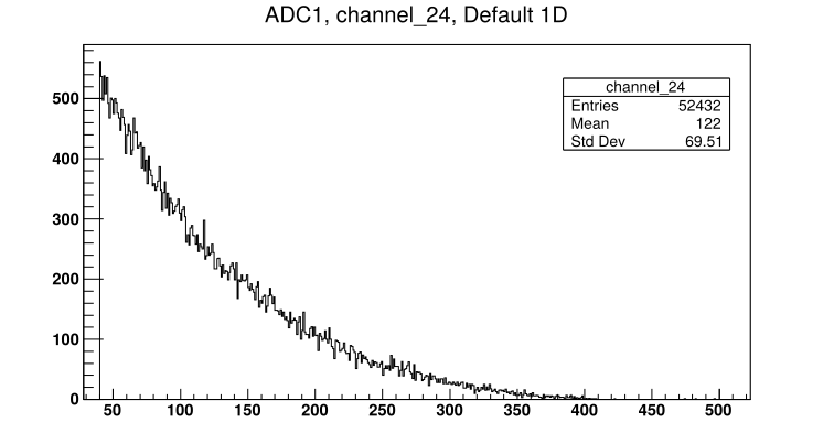
Still see scattered beam at low S2 strips #'s - see attached picture 1 for spectrum of the innermost S2 strip.
Performed further beam tuning to improve transmission.
After tuning: Using 10mm aperture FCC = 415pA (280 - 420pA). Using 3mm aperture FCC = 290pA.
Moved ladder to position #3 - CH2 XVI. Bombarded target with 3.0MeV 7Li 2+ and checked rate histogram on FAIR DAQ. ADC1 CH24 didn't show higher rates compared to other channels (eg ADC 1 CH10)
Moved ladder to position #7 - CH2 XIX
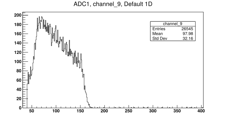
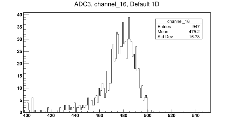
Run # 181126183711
- Run time: 616s
- Pulser ON, as before
- Target: CH2 XIX
- Beam: 3.0MeV 7Li 2+
- DT ~ 14%
- See attached picture 2 for sample S2 front strip spectrum. See attached picture 3 for diode spectrum.
|
| Attachment 1: 181126164509_ADC1_24.png
|
|
| Attachment 2: 181126183711_ADC1_Ch9.png
|
|
| Attachment 3: 181126183711_ADC3_Ch16.png
|
|
|
62
|
Mon Dec 3 16:39:42 2018 |
Thomas Chillery, Carlo Bruno, Tom Davinson, Raffaele Buompane | 3.0MeV 7Be on CH2 XIX |
On 26/11/2018:
Tuned beam for 3.0MeV 7Be 2+. Far S2 iris was closed during tuning.
After tuning, using 10mm aperture FCC = 5pA, using 3mm aperture FCC = 4pA.
Set ladder to position #7 - CH2 XIX
Run # 181126190248
- Run time: 1298s
- Pulser ON, as before
- Target: CH2 XIX
- Beam: 3.0MeV 7Be 2+
Left beam running and data collecting overnight
Run # 181126192446
- Run time: 47915s
- Pulser ON, as before
- Target: CH2 XIX
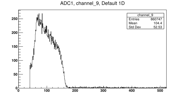
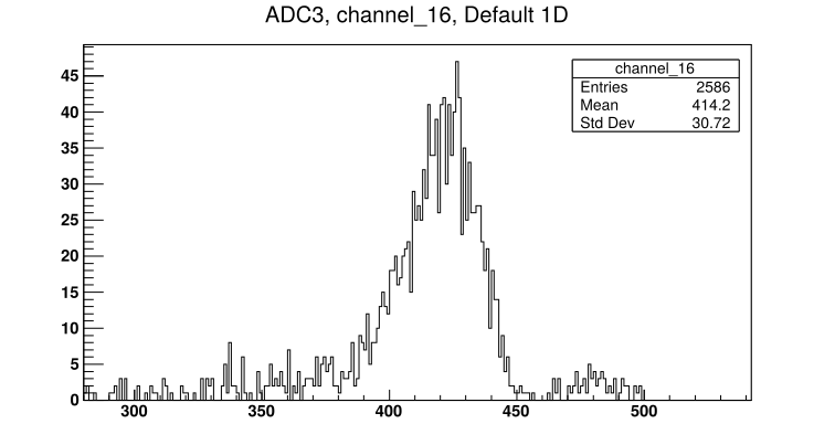
- Beam: 3.0MeV 7Be 2+
- See attached picture 1 for sample S2 front strip spectrum. See attached picture 2 for diode spectrum.
|
| Attachment 1: 181126192446_ADC1_Ch9.png
|
|
| Attachment 2: 181126192446_ADC3_Ch16.png
|
|
|
74
|
Tue Dec 4 09:38:18 2018 |
Thomas Chillery | 181122 Electronics Map |
See attached for S2 electronics map, following channels from S2 outputs to ADC inputs
For the 19/11/2018 - 29/11/2018 beamtime only the Far S2 was in operation |
| Attachment 1: 181122_Electronics_Channel_Map.ods
|
| Attachment 2: 181122_Electronics_Channel_Map.xls
|
|
1
|
Tue Aug 1 12:26:13 2017 |
Thomas Chillery | 10th - 22nd July 2017 Summary Report |
Attached is a report summarising work performed on the electronics and target chamber in CIRCE from the 10th to the 22nd July 2017.
Outstanding problems have also been listed. |
| Attachment 1: Summary.docx
|