| ID |
Date |
Author |
Subject |
|
6
|
Fri Feb 16 18:21:17 2018 |
Thomas Chillery | Iris arm problems |
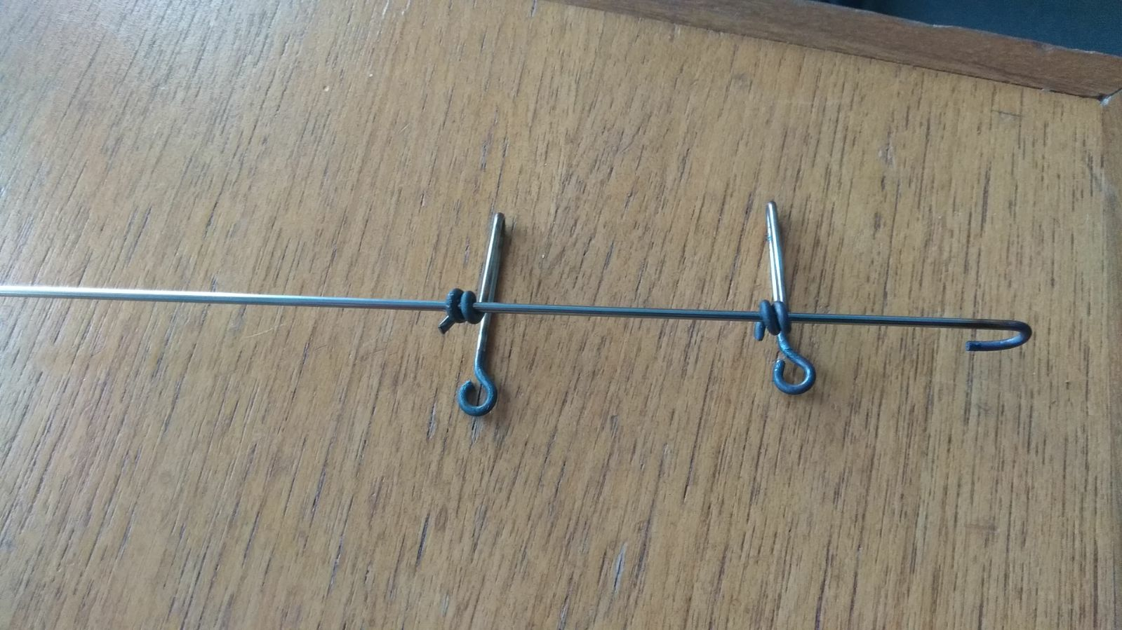
After lunch we were still having problems with the aperture hook, see first attached image highlighting the arm is located in close proximity (but not touching) the vacuum feedthrough and ribbon cable.
Meanwhile in Edinburgh Peter Black designed and built an additional component of the hook to assist in connecting it between the actuator and iris arms, see second attached image.
I decided enough time had been spent on this so far and to go ahead with testing the chamber vacuum. |
| Attachment 1: IMG_2677.JPG
|

|
| Attachment 2: ApertureArm_PetersSolution.jpg
|
|
|
59
|
Mon Dec 3 12:57:54 2018 |
Thomas Chillery, Carlo Bruno, Tom Davinson, David Rapagni | Finishing 6.0MeV 7Be 2+ and 7Li 2+ beam runs |
On 26/11/2018:
The accelerator and chamber setup were still operating after the overnight run.
Far S2 bias = -130V, leak I = 1.59uA. Diode bias = -70.1V, leak I = 0.00uA.
8:35 pressures (mBar):
- TPU1 = 8.6e-7
- TPU2 = 3.1e-7
- TPD1 = 6.1e-7
- TPD2 = 6.3e-7
- CHUP = Sensor Off
- CHDW = No Sensor
Checking for beam-induced background, moved target ladder to position # 2 - blank 10mm aperture
Run # 181126084821
- Run time: 1204s
- Pulser ON, as before
- Target: Blank 10mm
- Beam: 6.0MeV 7Be 2+
Using blank 10mm frame FCC = 6pA
Stopped run - CSSM magnet was switched on halfway through. This this the magnet located immediately downstream of the chamber and we were worried about it affecting the noise. Switched off CSSM magnet.
Run # 181126090936
- Run time: 1239s
- Pulser ON, as before
- Target: Blank 10mm
- Beam: 6.0MeV 7Be 2+
- DT ~ 8%
Moved ladder to position #5 - natC III
Run # 181126093314
- Run time: 1416s
- Pulser ON, as before
- Target: natC III
- Beam: 6.0MeV 7Be 2+
- DT ~ 8%
Moved ladder to position #2 - blank 10mm aperture. Closed far S2 iris and switched beam to 6.0MeV 7Li 2+.
Using 10mm aperture FCC = 360pA. Using 3mm aperture FCC = 300pA.
Moved ladder to position #4 - CH2 XVIII. Opened Far S2 iris.
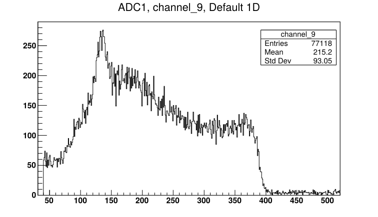
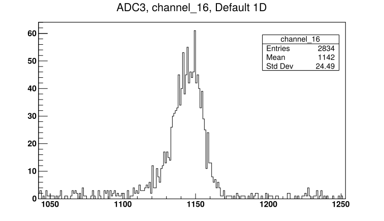
Run # 181126105357
- Run time: 1383s
- Pulser ON, 25Hz
- Target: CH2 XVIII
- Beam: 6.0MeV 7Li 2+
- DT ~ 12%
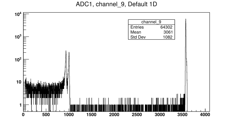
- See attached picture 1 for sample Far S2 front strip. See attached picture 2 for diode spectrum.
Ready to replace Far S2 12um mylar with 0.9um mylar protective foil |
| Attachment 1: 181126105357_ADC1_Ch9.png
|
|
| Attachment 2: 181126105357_ADC3_Ch16.png
|
|
|
63
|
Mon Dec 3 16:47:40 2018 |
Thomas Chillery, Carlo Bruno, Lizeth Morales | Finishing 3.0MeV 7Be measurements with CH2 XIX and natC III |
On 27/11/2018:
At 8:40 Far S2 bias = -130.0V, leak I = 1.74uA. Diode bias = -70.1V, leak I = 0.00uA.
Pressures (mBar):
- TPU1 = 8.3e-7
- TPU2 = 3.4e-7
- TPD1 = 6.5e-7
- TPD2 = 6.5e-7
- CHUP = Sensor Off
- CHDW = No Sensor
Preamps still drawing necessary currents.
Stopped overnight run of 3.0MeV 7Be 2+ on CH2 XIX
Checked beam current: FC4 = 2pA.
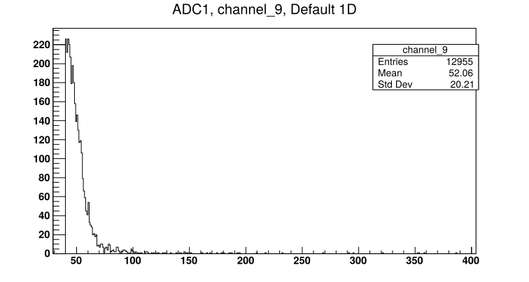
Moved ladder to position #5 - natC III
Run # 181127085408
- Run time: 627s
- Pulser ON, as before
- Target: natC III
- Beam: 3.0MeV 7Be 2+
- DT ~ 23%
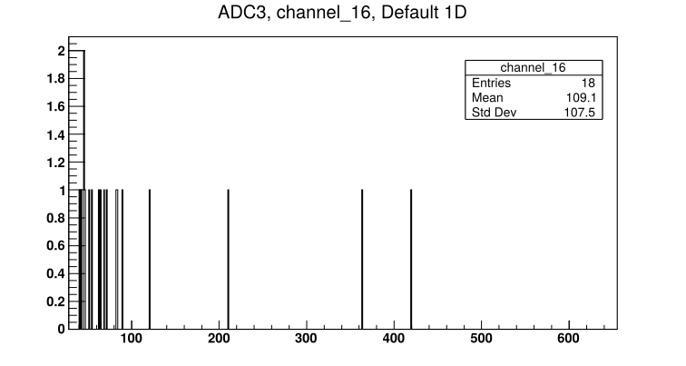
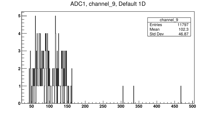
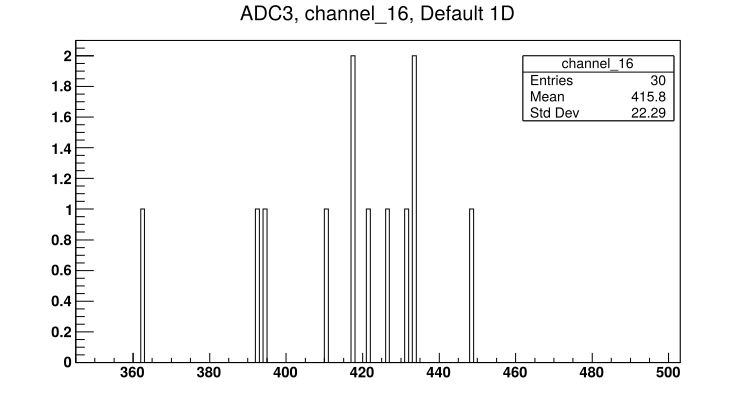
- See attached picture 1 for sample S2 front strip spectrum. See attached picture 2 for diode spectrum.
Moved ladder to position #2 - 10mm aperture
Run # 181127090808
- Run time: 601s
- Pulser ON, as before
- Target: Blank 10mm aperture
- Beam: 3.0MeV 7Be 2+
- DT ~ 10%
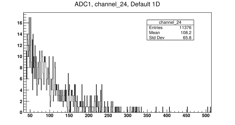
- See attached picture 3 for Far S2 innermost strip spectrum.
Moved ladder to position #7 - CH2 XIX
Run # 181127092128
- Run time: 663s
- Pulser ON, as before
- Target: CH2 XIX
- Beam: 3.0MeV 7Be 2+
- DT ~ 10%
- See attached picture 4 for sample S2 front strip spectrum. See attached picture 5 for diode spectrum.
* End of 7Be beam * |
| Attachment 1: 181127085408_ADC1_Ch9.png
|
|
| Attachment 2: 181127085408_ADC3_Ch16.png
|
|
| Attachment 3: 181127090808_ADC1_24.png
|
|
| Attachment 4: 181127092128_ADC1_Ch9.png
|
|
| Attachment 5: 181127092128_ADC3_Ch16.png
|
|
|
50
|
Sat Nov 24 15:05:40 2018 |
Thomas Chillery, Marialuisa Aliotta, Carlo Bruno, Lizeth Morales | FAIR DAQ |
The FAIR DAQ IP address: 192.168.1.90
The data is saved in /Local_Parts/Part0DE/
After each run we should copy the data to the 7Be shift folder: /home/circe/7Be_pp/181122/
We convert the data to a .root file via the command: fair2root ./run#
To convert the data to root we need to use the fairdef.in config file |
|
39
|
Fri Apr 13 15:08:04 2018 |
Thomas Chillery, Lucio Gialanella | End of shift - lab cleanup |
Date: 07/04/2018
Began dismounting detectors:
- All detectors powered off
- Closed line and quadrupole valves
- Preamp power off
- Stopped turbos
- Closed manual gate valve and T1600 Backing valve
- Stopped Ecodry 1 and 2 roughing pumps
- Switched off CAMAC and RAL electronic crates
- FC - 0 suppression voltage switched off (was set to -360V for beam measurements)
- Switched off both NIM crates
After venting the chamber I dismounted both S2 detectors and the 12um mylar in front of each detector
I also dismounted the diode from the chamber, but left the 0.9um mylar glued onto the 4mm diameter metal collimator
I left the target ladder in the chamber
I remounted the central and downstream lids onto the chamber, the diode mount with mylar was left mounted on the central lid
We performed a general cleanup around the lab of the tools used during this shift
At 19:30 we left the lab ^_^ |
|
71
|
Mon Dec 3 18:45:17 2018 |
Thomas Chillery, Raffaele Buompane | End of beamtime - Module settings |
Diode Ortec 571 Amplifier Settings:
- Fine gain: 10 (0.5 ->1.5)
- Course gain: 50
- Shaping time: 0.5us
- BLR AUTO: ON
- NEG: ON (Instead of POS)
- OUT: ON (Instead of Delay)
- Internal fine gain: 1X
Diode quad TFA settings:
- No clipping cable attached
- Internal jumpers:
- W1: Invert
- W2 and W3: 200ns differentiation
- W4: T2 (not set to 50ns or OUT)
- W5: X5 course gain
Diode quad CFD settings:
- Threshold at minimum: -177.6mV
- Short delay cable attached (1ns)
- Internal jumpers:
- W1: no jumper
- W2: Top
- W3: no jumper
Oscilloscope used: Tektronix TDS 3054B
RAL Crate Configuration:
| RAL Crate Position (from left) |
RAL Module ID |
| 1 |
XV |
| 2 |
II |
| 3 |
XI |
| 4 |
IV |
| 5 |
V |
| 6 |
VI |
| 7 |
VII |
| 8 |
VIII |
| 9 |
X |
| 10 |
XII |
| 11 |
XIII |
| 12 |
R |
| 13 |
S |
| 14 |
Q |
| 15 |
U |
| 16 |
W |
|
|
73
|
Mon Dec 3 19:04:20 2018 |
Thomas Chillery, Raffaele Buompane | End of beamtime - Items to be shipped back to Edinburgh |
To be shipped back to Edinburgh for repair:
|
Item
|
Quantity |
| ECL - NIM Convertor |
2 |
| Quad HV Supply |
1 |
| Quad TFA |
1 |
| SMC - SMC Cable |
1 |
| Central lid iris arm |
1 |
| Central lid - with iris |
1 |
| Diode mount |
1 |
| S2 2623-26 (505um) |
1 |
| PB-4 Pulser |
1 |
| BNC - SMC Bulkhead Connector (from close preamp box) |
1 |
| Lecroy 622 NIM module |
1 |
|
|
72
|
Mon Dec 3 18:55:31 2018 |
Thomas Chillery, Raffaele Buompane | End of beamtime - Cleanup |
On 29/11/2018:
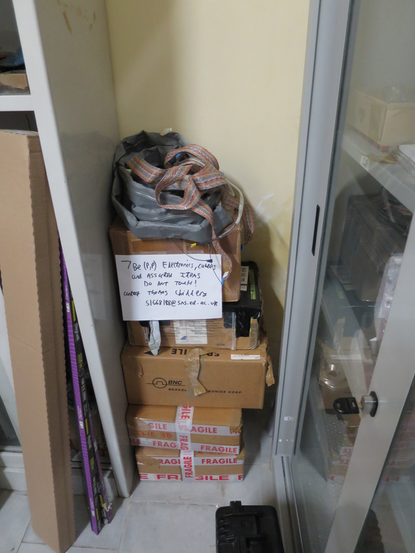
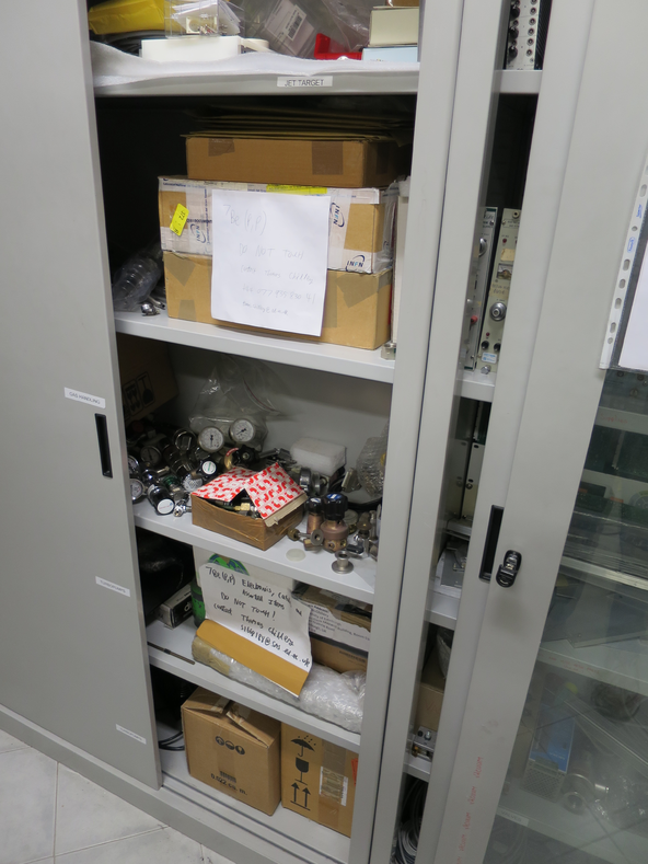
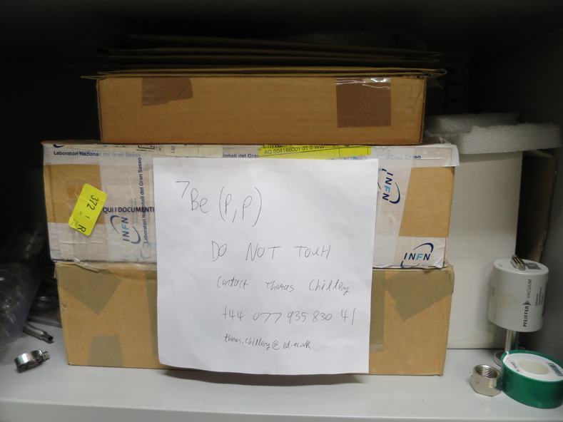
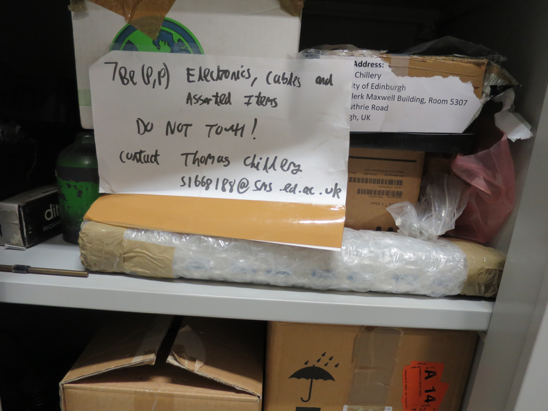
Dismounted S2 2323-18 (496um), 12um mylar, diode, and diodes 0.9um mylar.
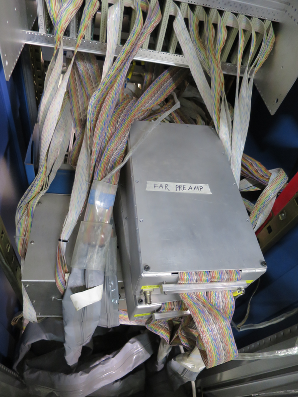
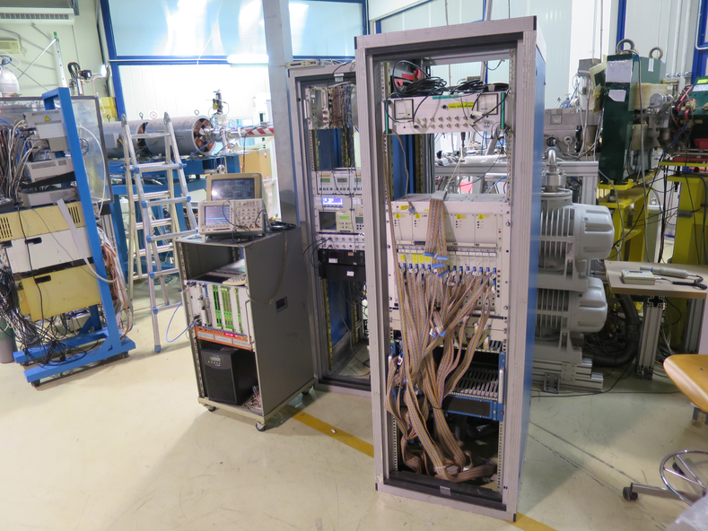
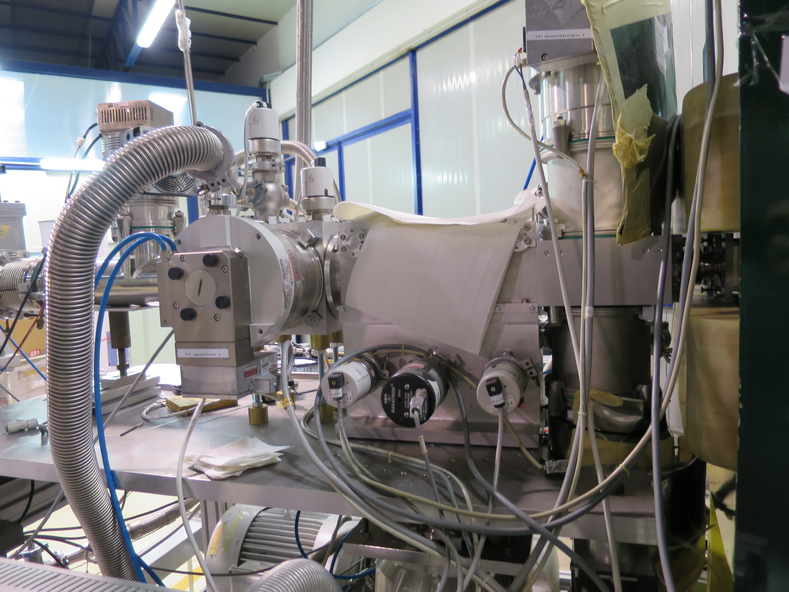
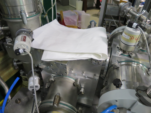
Performed general cleanup of lab. Boxed away cables and other parts. See attached pictures 1, 2, 3, and 4.
See attached picture 5, 6, 7, and 8 for status of electronics and target chamber at end of beamtime.
|
| Attachment 1: IMG_3381.JPG
|
|
| Attachment 2: IMG_3385.JPG
|
|
| Attachment 3: IMG_3383.JPG
|
|
| Attachment 4: IMG_3384.JPG
|
|
| Attachment 5: IMG_3386.JPG
|
|
| Attachment 6: IMG_3387.JPG
|
|
| Attachment 7: IMG_3388.JPG
|
|
| Attachment 8: IMG_3389.JPG
|
|
|
23
|
Tue Mar 6 15:55:04 2018 |
Thomas Chillery, Raffaele Buompane | End of February 2018 Shifts |
On 23/02/2018:
At the end of the February 2018 shifts the detectors bias settings were:
S2 bias = -130.3V, leak I = 2.42uA
Pin diode bias = -70.1V, leak I = 0.00uA.
Both detectors were switched off, the preamp power was also switched off.
At 18:22 the chamber pressures read:
TPU1 = 2.3e-6 mBar
TPU2 = 6.9e-7 mBar
TPD1 = 1.6e-6 mBar
TPD2 = 1.7e-6 mBar
CHUP = 5.7e-6 mBar
CHDW = 1.5e-5 mBar
We closed the manual gate valve and T1600 Backing Valves. We switched off the turbos and roughing pumps Ecodry 1 and 2.
The nim bin for the quad bias and other nim modules was switched off. The Lecroy 1434A CAMAC Crate was switched off. The RAL shaping amp crate was switched off.
We put away the S2 and pin diode detectors.
The alpha source was removed from the target ladder.
The target ladder was remounted in the following configuration:
| Position |
Target |
| 1 |
Blank 3mm |
| 2 |
No Target
|
| 3 |
CH2 VII |
| 4 |
CH2 III |
| 5 |
CH2 IV |
| 6 |
No Target |
| 7 |
No Target |
We performed a general tidy-up around the chamber and workspaces we used during the past 9 days.
I took the PB-5 Pulse Generator and three 64 Way - 2X32 Way ribbon cables (for minor modification) back to Edinburgh.
I also took the mylar we discovered in the beamline on Tuesday 20th as a keepsake/ reminder anything can happen
At ~20:00 we declared victory for the week. |
|
40
|
Wed Jul 11 15:55:35 2018 |
Thomas Chillery | Electronics Channel Map |
See attached for Electronics Channel Map spreadsheet.
This is valid for the February 2018 Beamtime; it maps out the Far S2 Strips onto the ADC channels
A map should be produced and updated for each beamtime to ensure S2 Strip -> ADC Channel is correctly documented. |
| Attachment 1: Electronics_Channel_Map.ods
|
|
49
|
Thu Nov 22 11:53:08 2018 |
Thomas Chillery, Marialuisa Aliotta, Carlo Bruno, Lizeth Morales | DAQ tests with alpha source |
The target ladder is set for position 7 - the double alpha source.
Looking at the FAIR DAQ, for the Far S2 the first RAL amplifier (XV) shows:
- Alphas at channel 700
- Pulser centroid at channel ~2640, with 9 channel FWHM -> corresponds to 44 keV FWHM at 4.91 keV/channel
The close S2 shows:
- Alphas at channel 700
- Same pulser centroid as far S2, with 6 channel FWHM -> corrsponds to 24 keV FWHM at 4.91 keV/channel
We reenabled the top ICU box channels 0 and 5 (disabled during Feb 2018 shift)
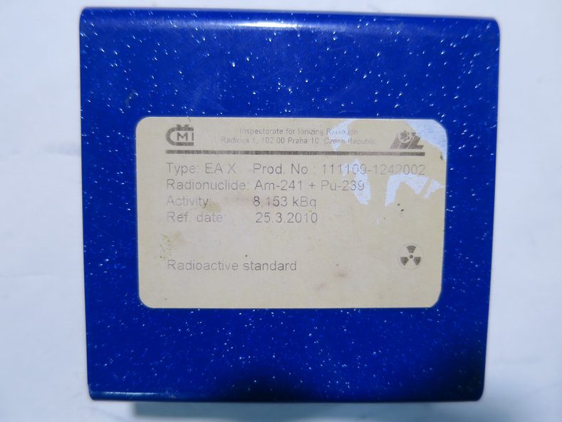
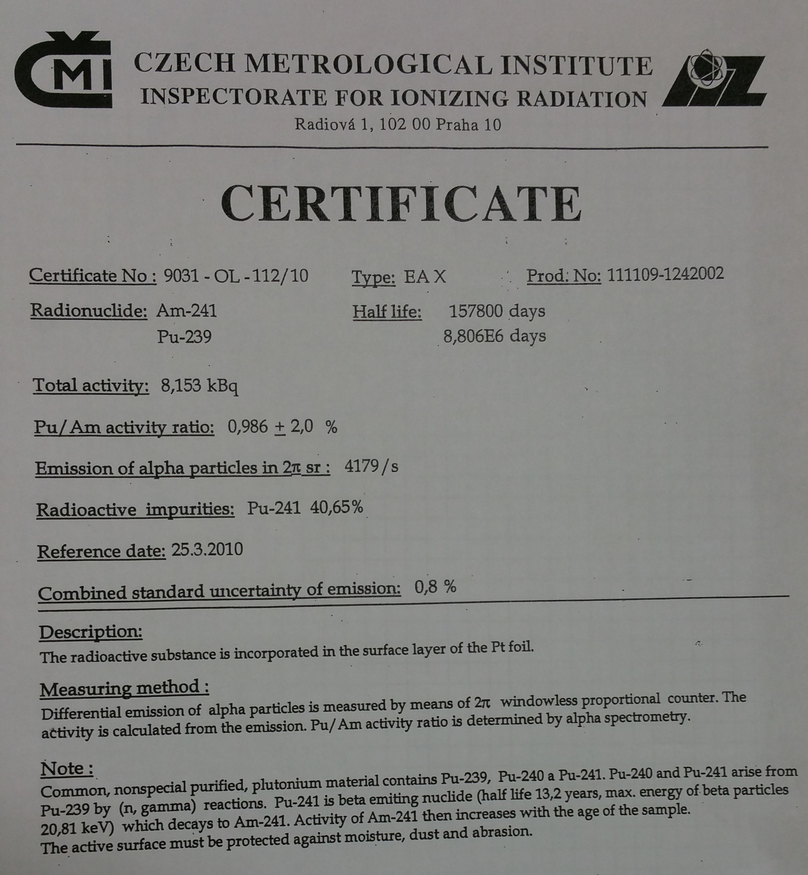
We started an alpha-source run using the 241Am and 239Pu source, type: EA X, product number: 111109-1242002. Photo of source storage case is attached.
Alpha activity at 25/03/2010: 8.153 kBq
We found the following strange behaviour
With DAQ list mode OFF:
- Trigger rate ~2300 - 2700/s
- Event mult ~ 140
- DT~18%
With DAQ list mode ON:
- Trigger rate ~300 - 900/s
- Event mult ~140
- DT ~ 70 - 90%
Currently ADC 2, 3, 4, and 5 are in use by the far and near S2's. ADC 6 and TDC 7 are not currently in use (we will need ADC 6 for the pin diode)
We set the lower threshold for ADC6 and TDC7 to 2046 out of 2047 channels - effectively disabling the two.
Now with list mode ON:
- Trigger rate ~ 1500 - 1700 /s
- Event mult ~ 65 - 70
- DT ~ 30 - 50 %
We restarted the DAQ machine
We started an alpha source run:
- Run number: 181122123034
- DT ~ 7 - 19%
- Trigger rate ~ 700 - 1000/s
- Event mult ~ 63
The PB-4 Pulser Settings are:
- Frequency: 250 Hz
- Delay: 1 us
- Rise Time: 0.1 us
- Fall Time: 100 us
- Reference: INT
- Polarity: +ve
- Amplitude on scope: 260mV
- Attenuation: X10 (X10 switch up, X2, X5, and the other X10 switch are down)
|
| Attachment 1: IMG_3329.JPG
|
|
| Attachment 2: AlphaSourceCertificate.jpg
|
|
|
48
|
Thu Nov 22 11:34:07 2018 |
Thomas Chillery, Marialuisa Aliotta, Carlo Bruno, Lizeth Morales | Continuing Electronic Chain Tests |
This morning at 8:35am the pressures read (in mBar):
- TPU1 = 2.0e-6
- TPU2 = 4.5e-7
- TPD1 = 8.1e-7
- TPD2 = 7.9e-7
- CHUP = 4.7e-7
- CHDW = 1.1e-5
The detectors were biased. Far S2 leak I = 1.54uA, near S2 leak I = 12.53uA.
It was discovered the ECL-NIM-ECL converter located immediately to the left of the pulser has broken channels - the last 8 channels. Instead of connecting the 32 pin ribbon cable to the input and taking lemo outputs 5 and 13, we are now connecting two single channel pin cables to inputs 1 and 2, and taking the corresponding lemo outputs.
We found RAL X sometimes doesn't produce a trigger for the pulser.
We replaced RAL I with RAL XIV, RAL XIV is bad.
We replaced RAL XIV with RAL XV, RAL XV is good.
We finished setting the RAL thresholds. |
|
21
|
Tue Mar 6 15:29:55 2018 |
Thomas Chillery, Raffaele Buompane | Collecting S2 Alpha Calibration Spectra at End of February Test Shifts |
On 23/02/2018:
We moved the target ladder to position 7, 5.019mm, with the alpha source facing downsteam.
At 17:17 we started the DAQ for a 15 minute alpha spectrum on the downstream S2. Save name: /Remote_Objs/RData_1/180223172135
The trigger rate ~ 160 Hz, Event Mult. = 5.8, Dead time = 0%
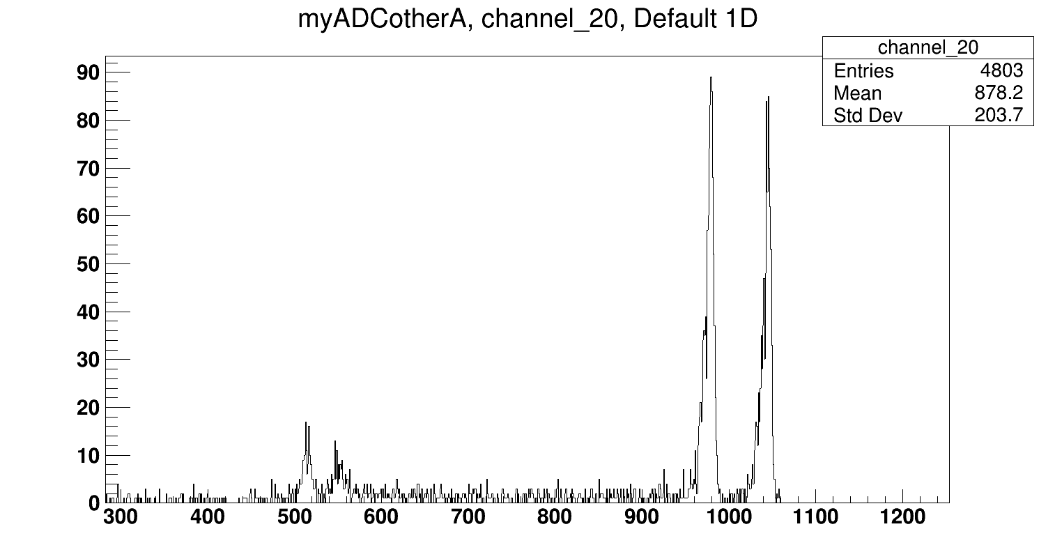
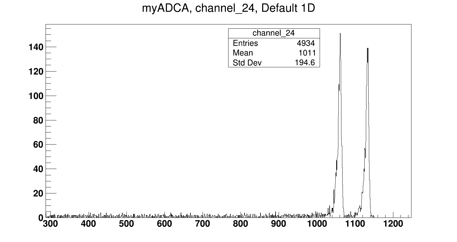
Note: For both this alpha spectrum and the beam measurement at 3.45 MeV 7Li (See entry #20) the pulser test input was also plugged into the diode preamp, hence the pulser peak appears at a lower channel in the S2 spectra. It still does not overlap the alpha peaks.
See attached "180223_Alpha_S2FrontStrip_ADC2CH20.png" for sample alpha spectrum of front S2 strip
See attached "180223_Alpha_S2BackStrip_ADC4CH24.png" for sample alpha spectrum of back S2 strip
In the S2 front strips we observed some additional peaks at lower channels ,~500, to the alpha peaks, but were unsure what they were. We decided to run a background to confirm whether this was caused by the source.
We moved the target ladder to position 1, 95.010mm, to position the alpha source as far from the central beam axis as possible. We then collected a background run for 5 minutes 16 seconds. Save name: /Remote_Objs/RData_1/180223174450.
We did not observe these low channel peaks in the background run, suggesting they are the result of the alpha source - perhaps a geometry effect. |
| Attachment 1: 180223_Alpha_S2FrontStrip_ADC2CH20.png
|
|
| Attachment 2: 180223_Alpha_S2BackStrip_ADC4CH24.png
|
|
|
41
|
Wed Nov 21 08:18:14 2018 |
Thomas Chillery, Marialuisa Aliotta | Checking Target Ladder Calibration |
On 19/11/2018:
There were three CH2 targets already mounted on the target frame, CH2 III, IV, and a damaged target. We dismounted these.
We noticed these previous target were mounted on the incorrect side of the target ladder, resulting in them being offset upstream from the central axis of the target ladder. This means for the previous tests in February and April 2018 the targets were mounted 3mm (target ladder thickness) upstream from the central position of the ladder.
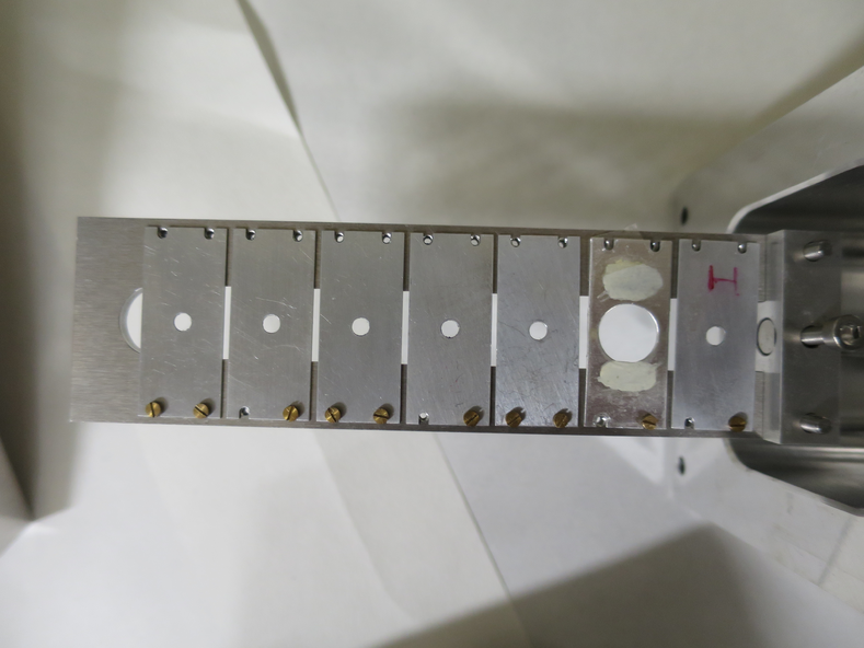
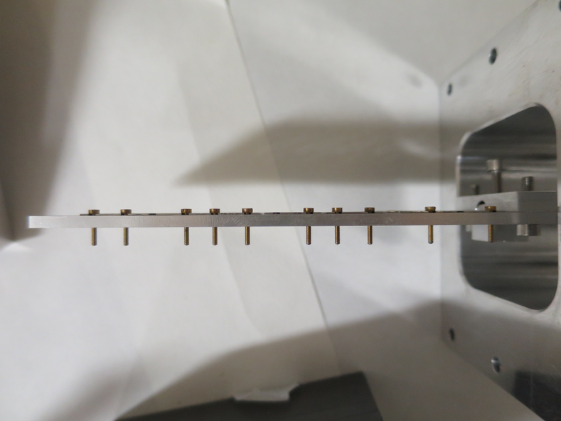
We mounted blank 10 and 3mm target frames onto the target ladder in the correct centralised position, see attached pictures 1 and 2.
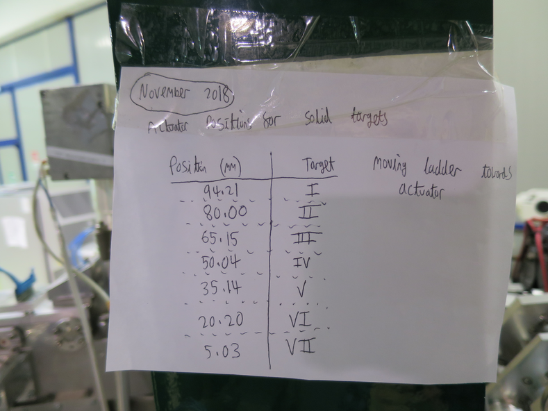
We performed the target ladder calibration using a downstream telescopic sight. The calibration is in agreement with the previous February 2018 calibration.
See attached picture 3 for the calibrated positions, this table is located on the magnet downstream of the chamber.
|
| Attachment 1: IMG_3204.JPG
|
|
| Attachment 2: IMG_3205.JPG
|
|
| Attachment 3: IMG_3200.JPG
|
|
|
60
|
Mon Dec 3 15:51:11 2018 |
Thomas Chillery, Carlo Bruno, Tom Davinson, David Rapagni | Changing far S2 protective mylar foil, preparing for 3.0MeV 7Li and 7Be |
On 26/11/2018, after 6.0MeV 7Be and 7Li beam measurements:
At 11:15:
Far S2 bias = -130.0V, leak I = 1.60uA. Diode bias = -70.1V, leak I = 0.00uA.
Pressures (mBar):
- TPU1 = 8.5e-7
- TPU2 = 3.1e-7
- TPD1 = 6.2e-7
- TPD2 = 6.3e-7
- CHUP = Sensor Off
- CHDW = No Sensor
Detectors and preamps switched off. Turbos off. Line valve closed. Manual and T1600 backing valves closed. Ecodry 1 and 2 off.
Waited for turbos to spin down.
Opened vent valve at Turbo Entrance 3. The automatic FCC valve immediately closed -> interlock tripped downstream of chamber and stopped turbo at FCC.
With FCC valve closed (allowing the chamber to continue venting) we restarted turbo at FCC -> spun up to operating 1000 Hz.
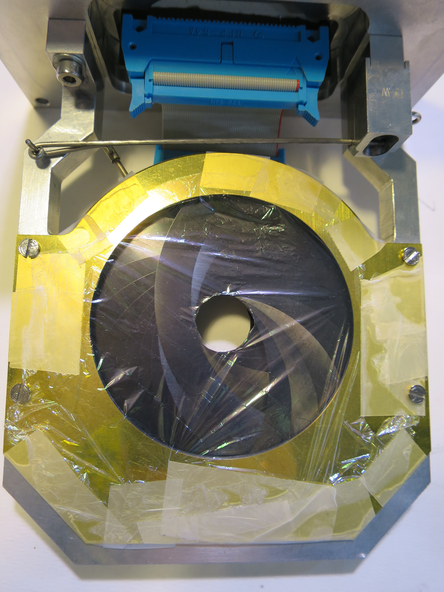
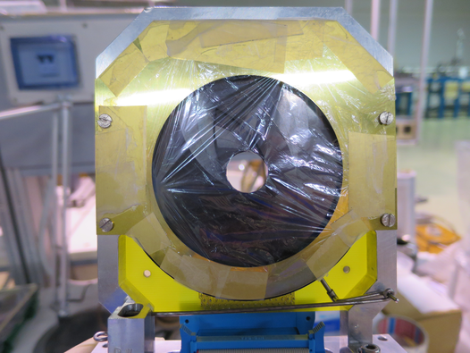
Once chamber finished venting, the far S2 was removed and its 12um mylar was replaced with 0.9um mylar ready for beam measurements at Elab = 3MeV. See picture 1 for 0.9um mylar mounted in front of far S2.
Far S2 remounted with far iris arm. Far S2 preamp remounted.
Preamp power on, currents drawn are good. Far S2 biased to -130.0V, leak I = 1.53uA. Diode biased to -70V, leak I = 0.00uA.
Noise looked ok. Detector biases off.
12:50 Ecodry 1 and 2 on. Started opening manual valve.
13:05 manual valve opened fully. T1600 valve opened.
13:10 Turbos on, pressures reached ~9e-5 mBar
Far S2 bias = -130.0V, leak I = 1.48uA. Diode bias = -70.1V, leak I = 0.00uA.
Set new RAL thresholds whilst monitoring rate: (counting from left of RAL rack)
- RAL #1 and 2: 20mV
- RAL #3: 15mV
- RAL #4 and 5: 10mV
- RAL #6: 15mV
13:25 Pressures (mBar):
- TPU1 = 1.0e-5
- TPU2 = 2.8e-6
- TPD1 = 2.5e-6
- TPD2 = 3.3e-6
- CHUP = Sensor Off
- CHDW = No Sensor
|
| Attachment 1: IMG_3273.JPG
|
|
|
76
|
Tue Dec 4 11:23:29 2018 |
Thomas Chillery | Chamber Dimensions |
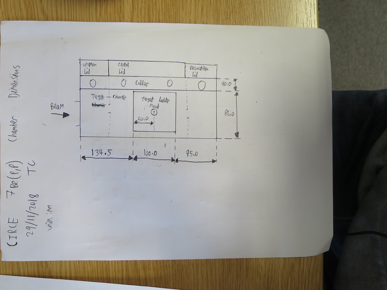
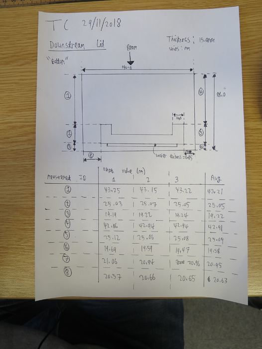
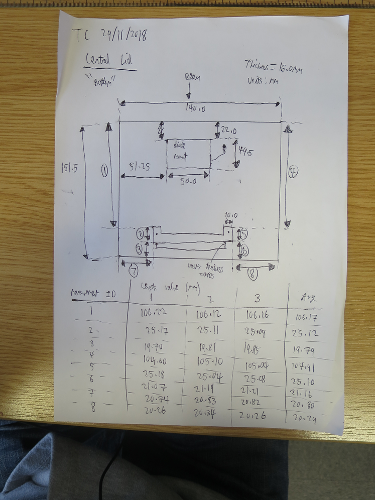
See attached pictures for measurements of the 7Be(p,p) chamber dimensions.
The target ladder center - Far S2 distance = 50 + 95 + 0.85 - (19.22+19.58)/2 = 126.45 mm |
| Attachment 1: IMG_3397.JPG
|
|
| Attachment 2: IMG_3398.JPG
|
|
| Attachment 3: IMG_3399.JPG
|
|
|
31
|
Thu Apr 12 12:47:04 2018 |
Thomas Chillery, Raffaele Buompane | Central S2 Alpha Calibration |
Date: 06/04/2018
We connected the analogue signals of RAL X, XII, XIII, and "R" to the 3rd ADC (Module 4)
We connected the analogue signals of RAL "S", "Q", "u", and "w" to the 4th ADC (Module 5)
We set the DAQ or to come from the central S2 and the diode monitor. The downstream S2 was not connected to the DAQ
At 15:14 we started the DAQ, a message appeared: Performing Automatic Clear. After a few seconds this message disappeared
At 15:15 we restarted the DAQ for a 15 minute alpha calibration, 241Am + 239Pu alpha source facing downstream, save name: RData_1/180406142007
The dead time = 3%, trigger rate ~ 1100Hz, Even mult = 5.5
At 15:31 the DAQ stopped, # good events = 1278692
The pressures in the chamber were:
- TPU1 = 3.0e-6 mBar
- TPU2 = 8.2e-7 mBar
- TPD1 = 1.6e-6 mBar
- TPD2 = 1.7e-6 mBar
- CHUP = 1.0e-5 mBar
- CHDW = 2.8e-5 mBar
The detector bias and leak I were:
- Downstream S2 bias = -130.1V, leak I = 2.53 uA
- Central S2 bias = -129.9V, leak I = 16.53 uA
- diode bias = -70.1V, leak I = 0.00 uA
Jeremias needed the alpha source, so after this run we vented the chamber. The detectors and preamps were switched off before starting the venting procedure.
At 16:15 Raffaele and Jeremias removed the target ladder and dismounted the alpha source from position VII. No other changes were made to the ladder.
The ladder was remounted and at 16:19 we started roughing down the chamber. At 16:29 the turbos were started.
At 16:40 the pressures read:
- TPU1 = 1.8e-5 mBar
- TPU2 = 3.8e-6 mBar
- TPD1 = 4.0e-6 mBar
- TPD2 = 5.6e-6 mBar
- CHUP = 1.9e-5 mBar
- CHDW = 5.1e-5 mBar
We were ready to repower the detectors and attempt to run beam on target.
|
|
69
|
Mon Dec 3 18:15:42 2018 |
Thomas Chillery, Raffaele Buompane | Calibration with alpha source - no mylar on Far S2 |
On 28/11/2018:
At 13:35: Far S2 bias = -130.0V, leak I = 1.55uA. Diode bias = -70.1V, leak I = 0.00uA.
Pressures (mBar):
- TPU1 = 3.3e-6
- TPU2 = 9,3e-7
- TPD1 = 1.2e-6
- TPD2 = 1.3e-6
- CHUP = Sensor Off
- CHDW = No Sensor
Switched off detectors, switched off pumps, closed manual and T1600 backing valves. Vented chamber.
Removed 0.9um mylar from far S2 - see attached picture 1 for mylar pre-removal. Removed far iris arm from downstream lid -> set iris to open position. Replaced far iris actuator with blank flange.
Remounted far S2 and far preamp - preamp still draws correct currents.
In air: Far S2 bias = -130.0V, leak I = 1.65uA. Diode bias = -70.1V, leak I = 0.01uA. Rate meter ~ 5500Hz.
Detectors bias off.
15:05 Ecodry 1 and 2 on, started opening manual valve.
15:20 Manual valve fully opened, T1600 backing valve opened, turbos on
15:30 Pressures (mBar):
- TPU1 = 2.2e-5
- TPU2 = 4.4e-6
- TPD1 = 4.0e-6
- TPD2 = 4.7e-6
- CHUP = Sensor Off
- CHDW = No Sensor
Far S2 biased to 130.0V, leak I = 1.59uA. Diode biased to -70.1V, leak I = 0.00uA. Ratemeter ~ 7000Hz.
Run numbers 181128153642, 181128161647, and 181128161758 are all alpha calibration runs. However DAQ connection was lost before the first run was started so the run time is not recorded for these.
Run # 181128162552
- Run time: 1408s
- Pulser ON, as before
- Alpha source
- S2 mylar: NONE
- DT ~ 20%
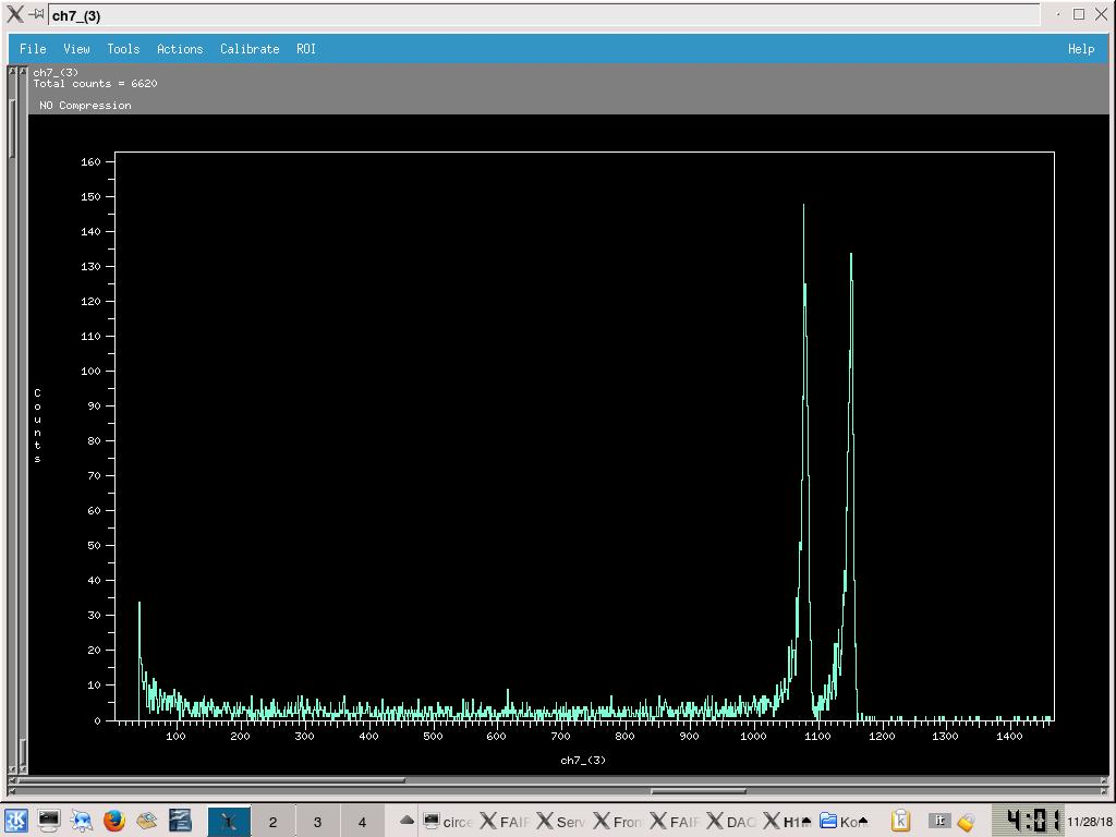
- See attached picture 2 for sample spectra from ADC2 Ch7 (ADC 3 in FAIR DAQ file browser)
16:45 Far S2 bias = -130.0V, leak I = 1.61uA. diode bias = -70.1V, leak I = 0.00uA.
Pressures (mBar):
- TPU1 = 2.8e-6
- TPU2 = 8.8e-7
- TPD1 = 1.2e-6
- TPD2 = 1.2e-6
- CHUP = Sensor Off
- CHDW = No Sensor
Switched off detectors, closed valves, turned off pumps, vented chamber.
|
| Attachment 1: IMG_3337.JPG
|
|
| Attachment 2: 182812_S2_Alpha_NoMylar.jpg
|
|
|
70
|
Mon Dec 3 18:30:53 2018 |
Thomas Chillery, Raffaele Buompane | Calibration with alpha source - 12um mylar on Far S2 |
On 28/11/2018:
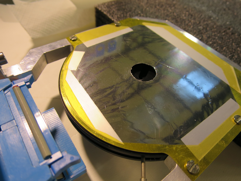
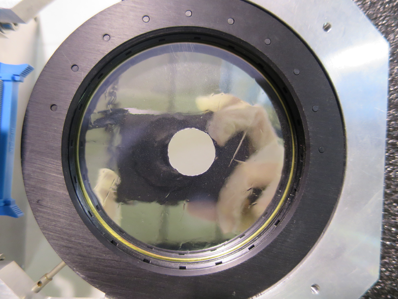
Mounted 12um mylar in front of far S2 - see attached pictures 1 and 2
In air: Far S2 biased to -130.0V, leak I = 1.61uA. Diode biased to -70.1V, leak I = 0.01uA -> 0.00uA. Rate meter ~ 4500Hz.
Detectors switched off
17:50 started Ecodry 1 and 2, started opening manual valve.
18:00 Manual valve fully opened, T1600 backing valve opened, Turbos switched on.
Once pressures ~ 1e-5mBar, far S2 bias = -130.0V, leak I = 1.59uA. Diode bias = -70.1V, leak I = 0.00uA.
18:08 Pressures (mBar):
- TPU1 = 3.0e-5
- TPU2 = 6.0e-5
- TPD1 = 5.2e-6
- TPD2 = 8.7e-6
- CHUP = Sensor Off
- CHDW = No Sensor
Run # 181128181421
- Run time: 1799s
- Pulser ON, as before
- Alpha source
- S2 mylar: 12um
- DT ~ 12%
Started overnight run:
Run # 181128184505
- Run time: 51706s
- Pulser ON, as before
- Alpha source
- S2 mylar: 12um
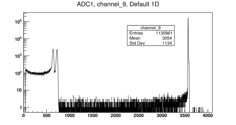
- DT ~ 8%
- See attached picture 3 for sample far S2 front strip spectrum
18:50 End of day check:
Far S2 bias = -130.0V, leak I = 1.60uA.
Diode bias = -70.1V, leak I = 0.00uA.
Pressures (mBar):
- TPU1 = 3.8e-6
- TPU2 = 1.2e-6
- TPD1 = 1.4e-6
- TPD2 = 1.6e-6
- CHUP = Sensor Off
- CHDW = No Sensor
On 29/11/2018: Alpha run stopped
9:05: Far S2 bias = -130.0V, leak I = 1.70uA. Diode bias = -70.1V, leak I = 0.00uA.
Detector biases and preamps off.
Pressures (mBar):
- TPU1 = 7.6e-7
- TPU2 = 3.5e-7
- TPD1 = 7.7e-7
- TPD2 = 7.3e-7
- CHUP = Sensor Off
- CHDW = No Sensor
Closed manual and T1600 backing valves. Stopped turbos. Stopped Ecodry 1 and 2.
Switched off Nim bin, RAL crate, and CAMAC crate
9:45 Opened venting valve |
| Attachment 1: IMG_3356.JPG
|
|
| Attachment 2: IMG_3363.JPG
|
|
| Attachment 3: 181128184505_ADC1_Ch9.png
|
|
|
68
|
Mon Dec 3 17:59:48 2018 |
Thomas Chillery, Raffaele Buompane | Calibration with alpha source - 0.9um mylar on Far S2 |
On 28/11/2018:
After pulser walkthrough (see eLog entry #67)
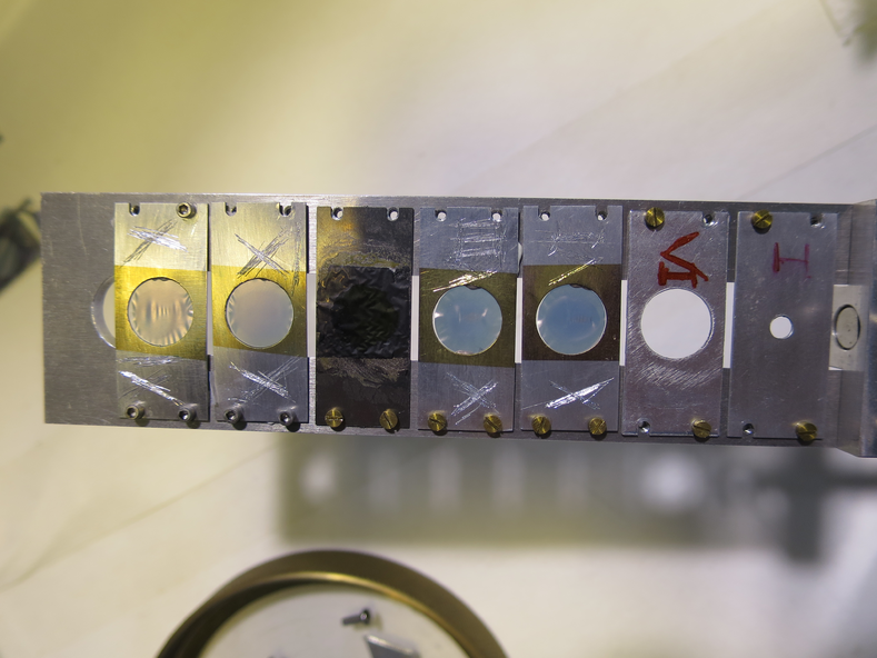
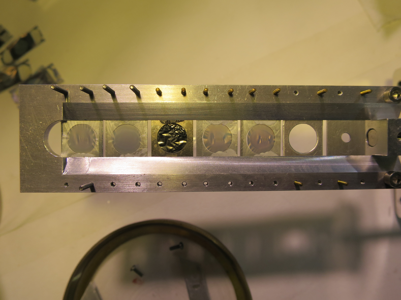
Dismounted targets from ladder - see picture 1 and 2 for upstream and downstream sides respectively
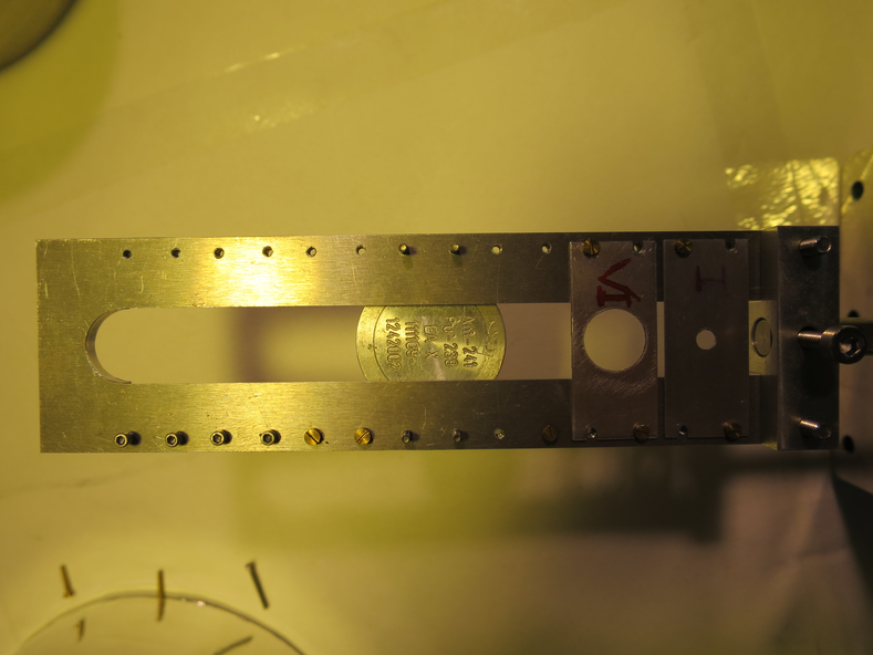
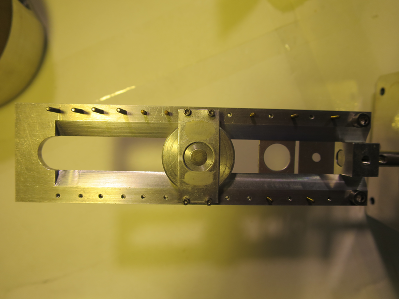
Mounted alpha source on ladder - see pictures 3 and 4 for upstream and downstream sides respectively
New target ladder configuration is now:
| Target Position |
Target |
| 1 |
Blank 3mm |
| 2 |
Blank 10mm |
| 3 |
Nothing |
| 4 |
Alpha-Source |
| 5 |
Nothing |
| 6 |
Nothing |
| 7 |
Nothing |
Dismounted thin CH2 target 50 - it was still attached to the collimator.
Remounted far S2 with 0.9um mylar, remounted far iris arm.
In air, pressures (mBar):
- TPU1 > 1000
- TPU2 > 1000
- TPD1 = 170 (above range)
- TPD2 = 73 (above range)
- CHUP = Sensor Off
- CHDW = No Sensor
Far S2 biased to -130.0V, leak I = 1.55uA. Diode biased to -70.1V, leak I = 0.01uA.
Ratemeter ~9200Hz.
Switched off detectors.
12:05 Ecodry 1 and 2 on. Started opening manual valve.
12:20 Manual valve opened fully, T1600 backing valve opened. Started turbos.
12:30 Pressures (mBar):
- TPU1 = 3.0e-5
- TPU2 = 5.1e-6
- TPD1 = 5.1e-6
- TPD2 = 7.5e-6
- CHUP = Sensor Off
- CHDW = No Sensor
Far S2 biased to -130.0V, leak I = 1.52uA. Diode biased to -70.1V, leak I = 0.01uA.
Rate meter ~ 7000Hz. Ladder set to position #4 - alpha source. Rate meter still ~ 7000Hz.
Run # 181128123940
- Run time: 3428s
- Pulser ON, as before
- Alpha-source
- S2 mylar: 0.9um
- DT ~ 22%
- See attached picture 5 for sample Far S2 front strip spectrum
|
| Attachment 1: IMG_3305.JPG
|
|
| Attachment 2: IMG_3307.JPG
|
|
| Attachment 3: IMG_3315.JPG
|
|
| Attachment 4: IMG_3313.JPG
|
|
| Attachment 5: 181128123940_ADC1_Ch9.png
|
|