| ID |
Date |
Author |
Subject |
|
19
|
Sun Feb 25 15:14:54 2018 |
Thomas Chillery, Lizeth Morales, David Rapagnani | Setup - Beam Tuning and Prepare Chamber for Measurement at 3.45MeV 7Li - Morning of 23rd | On the morning of 23/02/18 we aimed to complete beam tuning of 7Li at 3.45MeV.
At 8:43 CHUP = 7.2e-6mBar, CHDW = 1.9e-5mBar.
The S2 bias was ramped to -130.3V, leak I = 1.67uA. The diode bias was ramped to -70.1V, leak I = 0.01uA. The preamp power was also switched back on.
With no beam the DAQ monitor read a trigger rate ~ 50Hz and event multiplicity = 5.3.
We started beam tuning. A mistake was made where the accelerator side of the wrong valve was opened at the bending magnet, causing the beamline to be vented from 10^-7mBar to 10^-3mBar. Fortunately the line valve was closed, so the pressure of the chamber holding the detectors was unaffected.
We struggled with beam tuning for a few minutes, until we discovered the venting of the beamline tripped an interlock, causing turbo entrance 1 and 2 to be switched off. Restarting these turbos both improved the accelerator beamline vacuum and the beam tuning.
After beam tuning with the 3mm blank frame, we achieved beam currents:
FC-E0 (pre-chamber) = 250 pA
FC-E1 (post chamber and GSSI magnet) = 185pA
Transmission ~ 74%.
We felt satisfied and decided to remove the 12um mylar from the S2 ready to perform the measurement.
At 10:39 both detectors and the preamp power were switched off. The turbos were switched off. The manual gate valve and T1600 gate valves were closed. Ecodry pumps 1 and 2 were switched off. (We should write a procedure for pumping down and venting the chamber)
During venting we removed the S2 preamp box from the top of the chamber.
At 11:05 the CSSM gate valve interlock was tripped. In future we should make sure the CSSM magnet is OFF when not in use. David checked the pressures in and around the chamber, he concluded everything was fine.
After venting the chamber I removed the 12um mylar from the front of the S2.
I also removed the target ladder and rotated the alpha source 180 degrees to face downstream - this is so we can obtain a second alpha calibration of the S2 at the end of the beamtime.
Whilst handling the target ladder I noticed target VII is loose at one side, either from beam or my epoxy skills. I decided to leave all the targets mounted and we run beam on target 2, located at target ladder position 4, 50.015mm.
The target ladder configuration is now:
| Position |
Target |
| 1 |
Blank 3mm |
| 2 |
No Target |
| 3 |
CH2 VII |
| 4 |
CH2 III |
| 5 |
CH2 VI |
| 6 |
No Target |
| 7 |
Alpha source facing downstream |
At 12:18 the chamber was sealed up and we began roughing it down. At 12:29 we started the turbos and went to lunch.
At 13:02 after lunch: CHUP = 9.7e-6mBar and CHDW = 2.5e-5mBar.
We remounted the S2 preamp box back onto the downstream chamber lid, the preamp box lid was also remounted. The following pin diode preamp box cables were replugged in: input, -15V, +15V, +ve test, and HV.
At 13:25 the pressures read: CHUP = 9.6e-6mBar and CHDW = 2.5e-5mBar.
The S2 was biased to -130.3V, leak I = 1.56uA. The diode was biased to -70.1V, leak I = 0.01uA. Preamp power was applied -> correct currents drawn.
The target ladder was set to position 4, 50.015mm, target: CH2 930 ug/cm2 target III.
With no beam the DAQ trigger rate ~ 50Hz, the beam current at FC-E0 = 240pA.
We were confident to begun a beam measurement. |
|
14
|
Thu Feb 22 07:58:48 2018 |
Thomas Chillery, Tom Davinson, Raffaele Buompane, David Rapagnani, Lucio Gialanella | Setup - Beam Tuning and Prepare Chamber for Measurement at 3.0MeV 7Li | On 21/02/2018 we reattempted the beam tuning. We expected this to be easier now the rogue mylar is removed from the beamline.
At 8:30 we started the roughing pumps. At 8:37 the turbos were switched on. By 8:55 the preassures read: Up = 1.6e-5, and Down = 4.3e-5 mBar.
The preamp box was mounted on top of the chamber ready, the box lid was still left off.
The S2 was biased to -130.3V, leak current = 1.03 uA.
On FAIR DAQ with no beam: Trigger Rate ~ 8000/s, Event Mult = 5.0
The 10mm blank frame was in the beam axis. We began beam tuning. By 11:30 we had beam on the downstream faraday cup FC-E1 = 40pA, so now we can pass beam through the chamber - good!
We moved the target ladder to 95.010mm, swapping from the blank 10mm frame to the blank 3mm frame to assist in beam tuning. Now FC-E1 ~ 8pA.
We decided to move back to the 10mm frame to optimise tuning. The target ladder was moved back to position 80.024mm for this purpose.
We moved the slits located upstream from the bending magnet (close to FC-4) to 1.5X1.5mm.
We moved the GSI slits located before the quadrupole to optimise current on FC-0, the upstream faraday cup. We find the following slit positions:
Up = 0mm, Right = 1.5mm, Down = 5.5mm, Left = 5.5mm.
We also performed further tuning by adjusting the quadrupoles located at the immediate end of the tandem accelerator - note the beam tuning is very sensitive here.
After beam tuning we had the following currents:
For 10mm blank frame in beam axis: FC0 = 42pA, FCE1 = 30pA, transmission ~ 71%
For 3mm blank frame in beam axis: FC0 = 41pA, FCE1 = 13pA, transmission ~ 32%
We decided this was acceptable for testing
At 13:30 we switched off the S2 and vented the chamber.
After venting we did the following:
- Removed 12um mylar from the front of the S2
- Visually inspected the ribbon cable connections on the S2 connector and the vacuum feedthrough connector. I saw no loose connection and left the cable alone.
- Set the Si diode angle to 62 degrees relative to the beam axis (28 degrees relative to the normal of the beam axis) - in future we need a fixed angle mount to ensure this angle is reproducible
- Mounted targets on the ladder at the following positions:
| Position |
Target |
| 1 |
Blank 3mm |
| 2 |
Blank 10mm |
| 3 |
CH2 I |
| 4 |
CH2 II |
| 5 |
CH2 III |
| 6 |
CH2 VI |
| 7 |
natC I
|
The target ladder was set to position 3, looking from above I confirmed it was in the center of the beam axis.
The alpha source was removed as someone pointed out the ladder may be moved in such a way that beam hits the source. However later on (morning of 22/02/2018) I was informed this is being over cautious and we can leave the source at the far position 7 of the ladder during beam.
The ladder, downstream, and upstream lids were remounted on the chamber. The S2 (no mylar) was still on the downstream lid. The diode was still on the central lid.
The roughing pumps were switched on. However the following mistake was made: when both Ecodry 1 and Ecodry 2 were switched on, the automatic gate valve for Ecodry 1 was still open. This meant the chamber was evacuated at a fast rate, likely > 10mBar/s. When I noticed this after a few seconds of pumping the pressures read 10^-1mBar at the chamber upstream and downstream positions.
Speaking to David I learned Ecodry 1 may be switched on ready as long as the gate valve "T1600 Backing" is closed
Learning point: Ensure the automatic gate valve "T1600 Backing" is closed before pumping. This way we can control the roughing speed using the manual gate valve on Ecodry 2.
I wanted to inspect if anything was damaged in the chamber by this fast pump speed. The pumps were stopped and the chamber vented.
Upon visual inspection the S2 and 0.9um mylar in front of the diode were undamaged.
Target CH2 I on the ladder was loose at one side, the target ladder was removed and CH2 I at position 3 was replaced with CH2 VII.
Now the target ladder is in the following configuration: See attached IMG_2738.jpg
| Position |
Target |
| 1 |
Blank 3mm |
| 2 |
Blank 10mm |
| 3 |
CH2 VII |
| 4 |
CH2 II |
| 5 |
CH2 III |
| 6 |
CH2 V |
| 7 |
natC I |
At 16:45 the roughing pumps were switched on, this time with the "T1600 Backing" gate valve closed. The manual valve was cracked open.
By 17:01 the pressures read Up = 4.2e-1 mBar, Down = 4.1e-1 mBar.
At 17:08 the turbos were switched on.
At 18:07 the pressures read Up = 1.2e-5mBar, Down = 3.2e-5mBar.
We are ready to connect the preamp box for the S2, and also connect the preamp for the pin diode. |
| Attachment 1: IMG_2738.JPG
|

|
|
12
|
Tue Feb 20 17:03:08 2018 |
Thomas Chillery, Tom Davinson, Raffaele Buompane, David Rapagnani | Setup - Beam Tuning | The pumps were left on overnight, in the morning at 8:25 the pressure reads:
Up = 1.5e-5 mBar and Down = 4.0e-5 mBar.
We made a first attempt at collecting an alpha spectrum for the far S2 detector using ADC 2 and ADC 3. However ADC 3 appeared to be acting as a TDC for no obvious reason.
During this attempt we noticed ADC 2 channels 0, 1, and 5 had a high rate, and ADC 2 channel 8 had a low rate.
We moved the ribbon inputs on ADC 3 to ADC 4, the spectra on ADC 4 looked better. ADC 4 Channel 30 had a low rate.
We noticed ADC 3 was still active -> removing the ribbon inputs had no effect on the module writing to the DAQ. We raised the lower threshold of ADC 3 to 2046 (total 2047 channels), effectively stopping it from writing.
The thresholds for ADC 2 and ADC 4 were set to channel 40 for both. The thresholds on the RAL shaping amplifiers are set to 15mV.
At 9:09 we started collecting an alpha spectrum for a preset time of 900 seconds, finishing at 9:24. The dead time was 24% and the event multiplicity 3.2 (event mult. was 40 before removing ADC 3). The trigger rate was ~9kHz. The data were saved in /RemoteObjs/RData_1/180220091352/
To try and lower the trigger rate I removed the 6th breaker in the top IDC convertor box, which corresponds to the 5th channel of RAL I, which in turn corresponds to the 5th channel of ADC 2.
The trigger rate had risen (strangely) to ~12kHz, we saw ADC2 CH 0 had a high rate.So I removed the 1st breaker in the top convertor box, which corresponds to the 0th channel of RAL I, which in turn corresponds to the 0th channel of ADC 2.
Now the trigger rate was ~9kHz, with a good event rate ~ 40 Hz. We agreed that since the preamp box does not have its cover on there will be noise, particularly from the turbo located immediately downstream from the preamp box.
At 11:30 we started trying to tune the beam. Before sending beam I moved the target ladder to position 95.010mm, achieved by first moving the actuator to position 96mm and then back in position to account for backlash.
Note: All the target ladder calibration points were obtained by moving the ladder towards the actuator.
By 12:44 we were still tuning. We obtained a beam current of 200pA in FC-0, the faraday cup located ~1m upstream from the chamber, however we were unable to find the beam downstream from the chamber.
We were using the 3mm diameter blank frame for beam tuning, and decided to now attempt tuning with the 10mm blank frame.
We were using the only blank 10mm target frame available to support the alpha source, so we decided to vent the chamber and move this to an accesible part of the target ladder for beam. This would also allow us to inspect the beamline and check it is clear of obstruction with the telescope.
We switched off the detector and vented the chamber. I then removed the target ladder and switched the 10mm blank frame holding the alpha source with a 3mm blank frame. The 10mmblank frame was attached at position 2 of the ladder.
See attached (IMG_2709.jpg) for the first target ladder setup. See attached (IMG_2712.jpg) for the new target ladder setup.
We set the target ladder to 80.024mm for the 10mm blank frame, and then using the telescope confirmed it was in the beam axis. This involved removing the upstream lid and putting a piece of white paper in.
We then sealed the chamber and at 14:40 started the roughing pumps. The gate valve was cracked open -> we want a pumping speed <10mBar/s to avoid damaging the detectors and/or mylar foils.
At 15:04 the gate valve was fully opened and the turbos started. By 15:12 the pressures read: Up = 9.2e-5mBar, and Down = 1.0e-4mBar. The detector was biased at -130.3V with a leakage current 1.19uA.
With no beam the DAQ trigger rate ~ 6kHz.
At 15:29 we started the beam tuning with the 10mm blank frame in the beam axis.
During tuning the power supply on the 1st analysing magnet, located between the cathode source and accelerator, showed problems and was replaced.
At 17:50 I checked the S2 leakage current = 1.28 uA. The slight rise from 1.19 uA could be due to temperature fluctuations (8 degrees temp increase causes factor 2 difference)
At 18:20 we decided to vent the chamber and shine a light upstrean from the faraday cup FC-0. After switching off the detector and venting the chamber we discovered the piece of paper used to check the 10mm aperture alignment was left inside the upstream section of the chamber since the last time we vented. No beamspot was seen on the paper.
At 19:00 we restarted the roughing pump and cracked open the gate valve. At 19:03 the turbos were started. At 19:06 the pressures read Up = 7.0e-5, Down = 1.3e-4 mBar. The S2 was biased back to -130.3V, leak current = 1.20 uA.
We went back to tuning (third time today). With no beam we had a DAQ trigger rate ~ 2.6kHz, event multiplicity = 10.
We were able to see beam on FC-0, but unable to see beam on either of two faraday cups located downstream of the chamber. We decided to check the beamline again.
At 20:40 the detector was switched off. The turbos were then switched off. At 21:00 a tiny amount of air was allowed into the chamber to help slow the turbos, by 21:05 they were <12Hz. We vented the chamber.
After inspection of the beamline we discovered a new cause of the tuning problem. A small piece of mylar was in the bellow located downstream from FC-0. See attached IMG_2724.jpg.
We inspected the 12um mylar in front of the S2, it was not damaged, suggesting the rogue piece of mylar from the bellow is from a previous experiment.
We removed the rogue mylar and remounted the bellow to the beamline, we confirmed it was aligned using the telescope. We had a clear line of sight through the beamline, suggesting the problem is solved.
We declared victory.
At 22:30 we started the roughing pump for the section of beamline upstream from FC-0.
|
| Attachment 1: IMG_2712.JPG
|

|
| Attachment 2: IMG_2709.JPG
|

|
| Attachment 3: IMG_2724.JPG
|

|
|
36
|
Fri Apr 13 14:31:59 2018 |
Thomas Chillery, Lucio Gialanella | Setting up for 7Be 5.0MeV beam | Date: 07/04/2018
We changed to cathod 23 - 7Be
For beam tuning we:
- Closed downstream iris (actuator = 82.5mm)
- Closed central iris (actuator = 85.5mm)
- Set target ladder to position I (95.010mm) - 3mm collimator
We found the cathode wheel could no longer be turned remotely, instead Lucio rotated the wheel by hand to cathode 23. We had low beam current at the cathode.
Lucio called Raffaele to confirm the cathode number used yesterday (eLog entry #33)
- Cathode 23 is new -> still has copper on front of cathode which is removed during cesium sputtering -> process takes 2-3 hours
- Instead we moved to cathode 19 - 7Be. Thiis is the cathode used for 7Be yesterday
We decided that when noting faraday cup currents we should also record the offset as well. Previously I was recording the measured minus offset value.
After tuning, and setting the CSSM magnet to 918.3 mT:
- FC - 4 = 410 - 260 = 150 pA (drifted from 450 - 260 = 190 pA)
- FC - 0 = 92 - 0 = 92 pA (drifted from 107 - 0 = 107 pA)
- FC - E1 = 50 - 5 = 45 pA
We felt ready to start a measurement with 7Be
|
|
47
|
Wed Nov 21 09:34:26 2018 |
Thomas Chillery, Marialuisa Aliotta, Carlo Bruno | Setting up chamber both for tests under vacuum and physics measurement | Today we mounted the far aperture used to control the far iris. No problems were encountered with this.
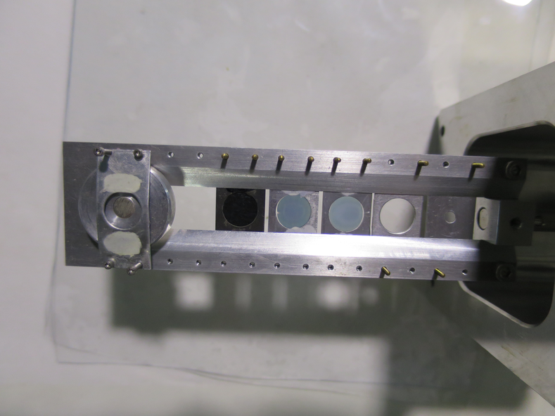
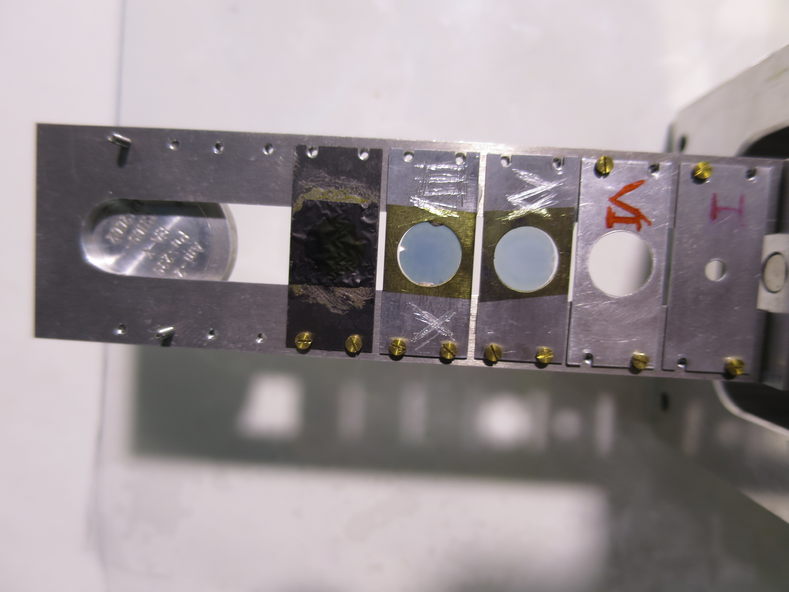
We mounted the target ladder with the following configuration, see also pictures 1 and 2:
| Target # |
Target |
| I |
Blank 3mm |
| II |
Blank 10mm |
| III |
CH2 XV |
| IV |
CH2 XVIII |
| V |
natC 3 |
| VI |
- |
| VII |
Alpha Source |
The alpha source is 241Am + 239Pu
We also have mounted the near and far S2's with 12um mylar, and the pin diode with 0.9um mylar.
We only had the far iris arm actuator mounted, because a new iris arm for the near iris mount was being manufactured in the CIRCE workshop.
During ~midday through the early afternoon we found vacuum problems. These were solved by remounting the far chamber lid, and also remounting the far iris arm actuator (This had incorrect length bolts).
The new iris arm for the near S2 came back from the workshop, unfortunately we still could not mount it. We decided against mounting this iris arm, and instead mount the near S2 with the iris completely open and the 12um mylar protective foil.
We will only be able to measure at Elab = 4MeV, becasue at Elab = 6MeV the 7Li penetrates through 12um mylar and so we would be risking the near S2 during beam tuning (not an option!).
We mounted the near S2 with iris open and 12um mylar foil. The far S2 was already mounted with 12um foil and the iris arm aperture. The far S2 iris was opened fully (setting 1.5mm on actuator) ready for pumping and alpha source measurement.
At 16:50 we started the Ecodry 1 and 2 pumps and opened the manual gate valve. By 16:55 we fully opened the gate valve and also the T1600 backing valve, allowing both ecodrys to pump on the chamber. We then switched on the turbos.
By 17:20 the pressures read (in mBar):
- TPU1 = 3.4e-5
- TPU2 = 3.3e-6
- TPD1 = 3.4e-6
- TPD2 = 4.1e-6
- CHUP = 1.2e-5
- CHDW = 2.8e-5
During pump down we mounted the preamp boxes with daisy chained BNC cables.
We applied preamp power, correct currents drawn: ~1.5A for +ve and ~500mA for -ve
Far S2 biased to -130V, leak I = 1.46uA. Near S2 biased to -130V, leak I = 2.48uA.
Checking for noise, we see the following RMS noise in the RAL amps:
| RAL # |
RMS noise [mV] |
| I, II, XI |
~25 |
| IV |
~10 |
| V, VI |
~15 |
| X, XII, XIII, R S, Q |
~15
|
Diode biased to -70V, leak I = 0.02uA
We tested for ground loops - no obvious loops found for either S2 preamp
We connected the RAL amps to the FAIR DAQ, and started an alpha source run with pulser. The dead time was excessively high, ~90%
We started adjusting RAL thresholds up to RAL S, then we called it a day.
The Far S2 leak I = 1.4 uA, near S2 leak I = 3.3 uA.
We unbiased the detectors, switched off the NIM, CAMAC, and RAL crates, and also switched off the preamp power. We didn't wanted anything damaged from potential overnight thunderstorms.
At 20:35 the pressures read (in mBar):
- TPU1 = 6.3e-6
- TPU2 = 8.0e-7
- TPD1 = 1.2e-6
- TPD2 = 1.2e-6
- CHUP = 6.2e-6
- CHDW = 1.4e-5
|
| Attachment 1: IMG_3223.JPG
|
|
| Attachment 2: IMG_3224.JPG
|
|
|
51
|
Sat Nov 24 15:07:00 2018 |
Thomas Chillery, Marialuisa Aliotta, Carlo Bruno, Lizeth Morales, Tom Davinson | Searching for causes of noise | On 22/11/2018 in the afternoon:
We increased the ADC thresholds to 40 (previously 8).
For an alpha source with pulser connected, the event multiplicity dropped from ~63 to ~10. Dead time ~ 7%
Checking the timing signals for the near S2:
- RAL X channels 0 - 5 bad, 6 and 7 good -> disconnected timing
- RAL U, XII, XIII, R, and S good
- RAL W channels 0 - 5 good, 6 and 7 bad
- RAL Q all bad -> disconnected timing
Started alpha source run with pulser (same pulser settings as run before)
After run the Far S2 RAL thresholds set to 10mV, the close S2 thresholds set to 50mV
Started alpha source run, no pulser
Stopped run due to poor alpha rate -> ECL-Nim ribbon cable disconnected.
Checking bias:
- Far S2 bias = -130V, leak I = 1.91uA
- Close S2 bias = -129.9V, leak I = 13.11uA
- diode bias = -70V, leak I = 0uA
Vented chamber and checked 12um mylar foil in front of close S2 - no visual damage. LEft
Close detector changed: S2 2623-26 (505um) replaced with S2 2623-18 (508um). Mounted new S2 in close position with 12um mylar
Removed alpha source - needed by other experiment. Otherwise target ladder configuration is same as eLog entry #47
Checked grounding cables going from preamps to ICU boxes were tightly connected
Attempted to bias close S2 -> no leak current! Left lab for the day.
The next morning (23/11/2018):
We found the BNC - SMC bulkhead connector attached to the near S2 preamp box is missing a pin. We dismounted the near S2.
We observed ~50kHz noise on Far S2, this is removed when we lifted the preamp - ICU box ribbon cables away from the chamber vacuum gauges. |
|
11
|
Tue Feb 20 16:57:49 2018 |
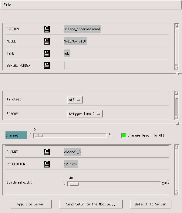
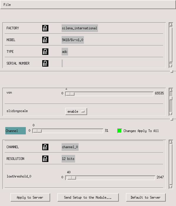
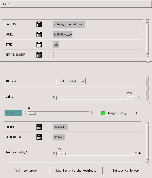
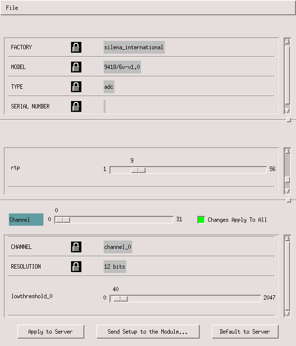
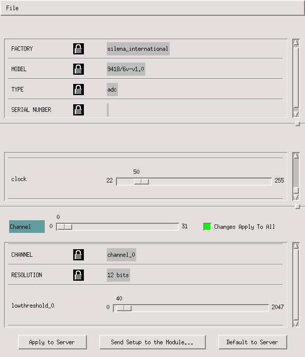
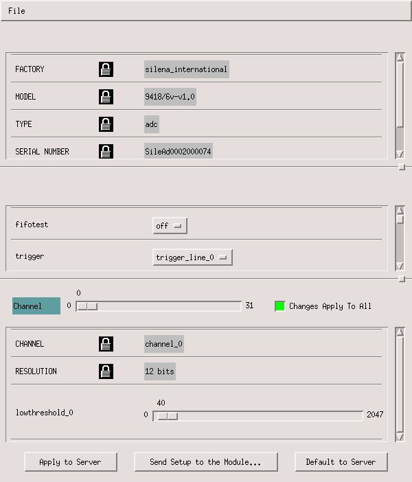
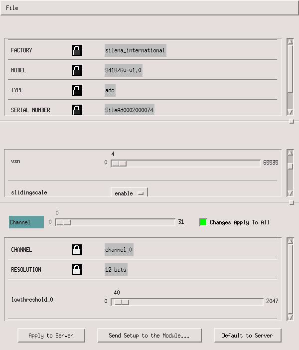
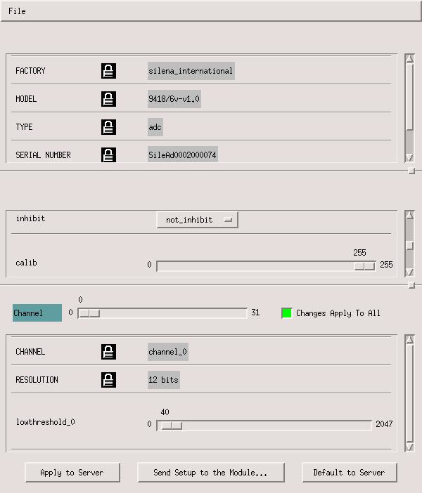
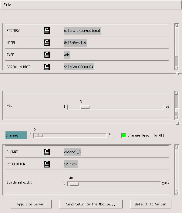
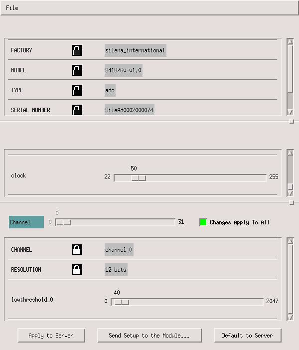
Thomas Chillery | Screenshots - ADC 2 and ADC 4 settings, and example pulser walkthrough | |
| Attachment 1: ADC2_Settings1.jpg
|
|
| Attachment 2: ADC2_Settings2.jpg
|
|
| Attachment 3: ADC2_Settings3.jpg
|
|
| Attachment 4: ADC2_Settings4.jpg
|
|
| Attachment 5: ADC2_Settings5.jpg
|
|
| Attachment 6: ADC4_Settings1.jpg
|
|
| Attachment 7: ADC4_Settings2.jpg
|
|
| Attachment 8: ADC4_Settings3.jpg
|
|
| Attachment 9: ADC4_Settings4.jpg
|
|
| Attachment 10: ADC4_Settings5.jpg
|
|
| Attachment 11: BKG_zoombeam1.jpg
|
|
|
67
|
Mon Dec 3 17:51:46 2018 |
Thomas Chillery, Raffaele Buompane | Pulser Walkthrough | On 28/11/2018:
Performed pulser walkthrough, Run # 181128090835
- Run time: 1986s
- Pulser ON, amplitude changed
- Target: None
- Beam: None
- DT ~ 11%
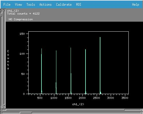
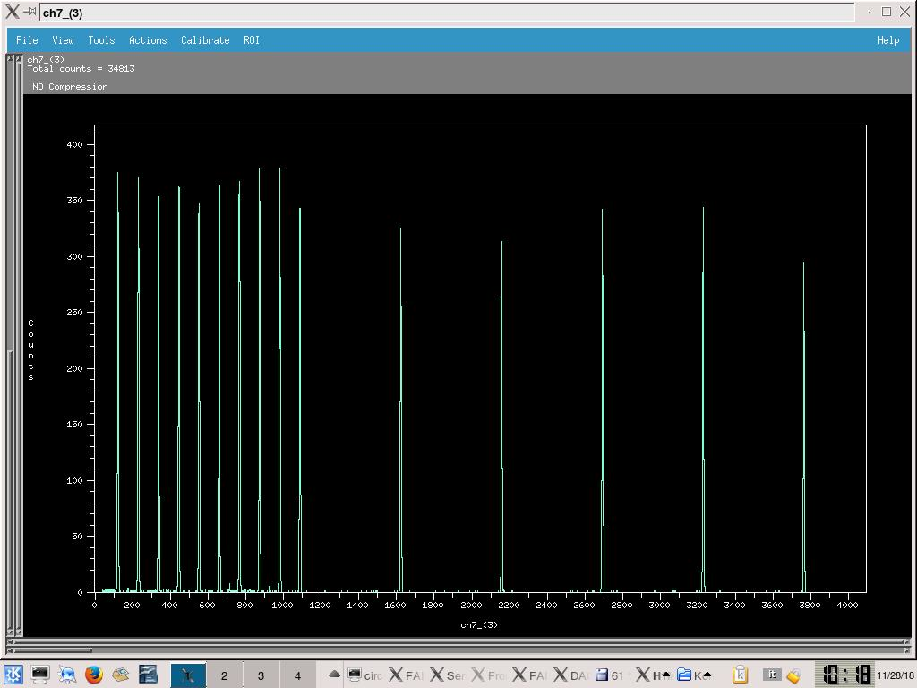
- See attached picture 1 for sample pulser walkthrough spectrum, ADC 2 channel 3 (ADC 3 in DAQ file browser)
Pulser amplitudes swept through (measured amplitude checked after collecting pulser walkthrough to ensure no additional load was placed on pulser):
| Pulser Amplitude Setting |
Pulser Measured Amplitude (mV) |
| 70000 |
366 |
| 60000 |
318 |
| 50000 |
268 |
| 40000 |
206 |
| 30000 |
155 |
| 20000 |
102 |
| 18000 |
92.4 |
| 16000 |
82.8 |
| 14000 |
72.8 |
| 12000 |
62.4 |
| 10000 |
51.8 |
| 8000 |
42.0 |
| 6000 |
32.0 |
| 4000 |
22.0 |
| 2000 |
11.4 |
After walkthough pulser amplitude setting set back to 70000, all other settings left unchanged
Far S2 and diode biases switched off. Preamp power off. Line valve and FCC valve closed. Turbos off. Manual and T1600 backing valves closed. Ecodry 1 and 2 off. Waited for turbos to spin down.
By 10:20 turbos had finished spinning, vented chamber ready to mount alpha source. |
| Attachment 1: 182811_PulserWalkthrough.jpg
|
|
|
46
|
Wed Nov 21 09:28:06 2018 |
Thomas Chillery, Marialuisa Aliotta, Carlo Bruno, Lizeth Morales | Problem encountered with near iris arm | On 20/11/2018:
After the electronics tests in air (see eLog entry #44) we started to setup the chamber for vacuum tests with an alpha source.
We started mounting the aperture used for controlling the near iris arm, however we encountered a problem. The iris arm got stuck and could not move in either direction (into or out of the chamber)
We dismounted both preamps. After bending the near iris arm's hook we managed to dismount the chambers central lid.
Before doing anything else, we dismounted the near S2 and 12um mylar foil.
A new iris arm for the near iris needs to be manufactured by the workshop in CIRCE. The workshop was closed for the end of the day, so we also stopped for the day. |
|
52
|
Sat Nov 24 16:29:10 2018 |
Thomas Chillery, Marialuisa Aliotta, Carlo Bruno, Tom Davinson, Raffaele Buompane | Preparing setup for 7Li beam | On 23/11/2018:
10:15 started pumping down chamber with Ecodry 2
RAL thresholds:
- First 4 RALs = 10mV
- 5th RAL = 17mV
- 6th RAL = 20mV
- 7th and 8th RALs ECL disconnected
- 9th - 16th RALs not in use (no near S2)
10:30 pressures ~ 1mBar, opened T1600 backing valve, Turbos switched on
10:35 pressures (mBar):
- TPU1 = 5.2e-5
- TPU2 = 6.4e-6
- TPD1 = 6.0e-6
- TPD2 = 8.7e-6
- CHUP = 2.3e-5
- CHDW = 5.5e-5
Biased detectors: Far S2 bias = -130V, leak I = 1.54uA. Diode bias = -70V, leak I = 0.02uA.
Replaced diode TFA, now using channel 4 on new TFA. Diode connected to 3rd ADC channel 16 (counting from 0)
Started pulser only run
Closed far S2 iris (82.5mm actuator setting). Set target ladder to blank 10mm target frame.
Disconnected vacuum gauges located below chamber on same side as target ladder is mounted - noise improved
Started pulser only run
|
|
55
|
Mon Nov 26 17:13:45 2018 |
Thomas Chillery, Carlo Bruno, Tom Davinson, Lucio Gialanella | Preparing chamber for 4MeV 7Be 2+ beam | On 24/11/2018:
At 8:35 the chamber pressures read (mBar):
- TPU1 = 2.2
- TPU2 = 2.2
- TPD1 = 2.2
- TPD2 = 2.0
- CHUP = Sensor Off
- CHDW = No Sensor
The chamber was vented and the CH2 XV target replaced with new ones.
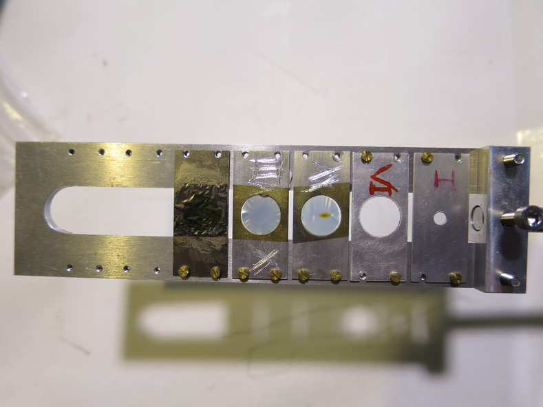
See picture 1 for target ladder after dismounting - the beam spot from 7Li is clearly visible on CH2 XV.
The target ladder configuration is now:
| Target # |
Target |
| 1 |
Blank 3mm Aperture |
| 2 |
Blank 10mm Aperture |
| 3 |
CH2 XVI (840 +/- 40 ug/cm^2) |
| 4 |
CH2 XVIII (820 +/- 40 ug/cm^2) |
| 5 |
natC III (590 ug/cm^2) |
| 6 |
CH2 XX (880 +/- 40 ug/cm^2) |
| 7 |
CH2 XIX (890 +/- 40 ug/cm^2) |
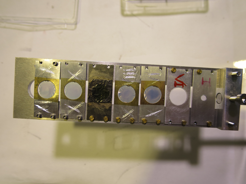
See picture 2 for the new configuration.
The target ladder was remounted and at 9:15 the chamber pumped down. The far S2 still has the 12um mylar protective foil.
By 9:30 the pressures read (mBar):
- TPU1 = 4.6e-5
- TPU2 = 7.4e-6
- TPD1 = 6.8e-6
- TPD2 = 8.7e-6
- CHUP = Sensor Off
- CHDW = No Sensor
The Far S2 was biased to -130V, leak I = 1.38 uA. The diode biased to -70V, leak I = 0.00uA
A beam of 7Li 2+ 4.0MeV was focused onto the target position.
After focussing, FC4 = 260 pA, FCA = 250 pA. Both of these faraday cups are before the target chamber.
After focussing with the 10mm aperture, FCC = 195 pA. Focussing with the 3mm aperture, FCC = 190 pA. Faraday cup C (FCC) is after the target chamber.
A spectrum was collected for 7Li 4.0MeV
Run # 181124101041
- Run time: 717s
- Pulser ON, 25 Hz, as before
- Target: CH2 XVI
- Beam: 4.0 MeV 7Li 2+
- Trigger rate: 3285/s
- DT ~ 6%
|
| Attachment 1: IMG_3231.JPG
|
|
| Attachment 2: IMG_3232.JPG
|
|
|
75
|
Tue Dec 4 09:40:31 2018 |
Thomas Chillery | Preliminary measurements of target activation using geiger counter | On 29/11/2018 at 17:40 a rough measurement of the irradiated target activity was performed using a geiger counter.
The geiger counter was a calibrated Berthold LB124, which was placed a fixed 15mm distance from each target.
The calibration was such that 1cps = 37kBq.
The LB124 counter measured a background count of 0.5cps
| Target |
Irradiated with |
Berthold LB124 [cps] |
| CH2 XV |
7Li 4.0MeV |
0.0 |
| CH2 XVI |
7Li and 7Be 4.0MeV, 7Li 6.0MeV |
6.8 |
| CH2 XVIII |
7Li and 7Be 6.0MeV |
0.9 |
| CH2 XX |
Not used |
0.5 |
| natC III |
7Li and 7Be 3.0MeV, 4.0MeV, and 6.0MeV |
0.0 |
| CH2 XIX |
7Li and 7Be 3.0MeV |
11.5 |
|
|
4
|
Thu Feb 15 20:45:27 2018 |
Thomas Chillery | Planning - Target Chamber CAD diagram | Find attached the latest CAD diagram of the Target Chamber, drawn by Peter Black |
| Attachment 1: solid_target_11.pdf
|

|
|
22
|
Tue Mar 6 15:41:53 2018 |
Thomas Chillery, Raffaele Buompane | Pin Diode Pulser Walkthrough at End of February Shifts | On 23/02/2018:
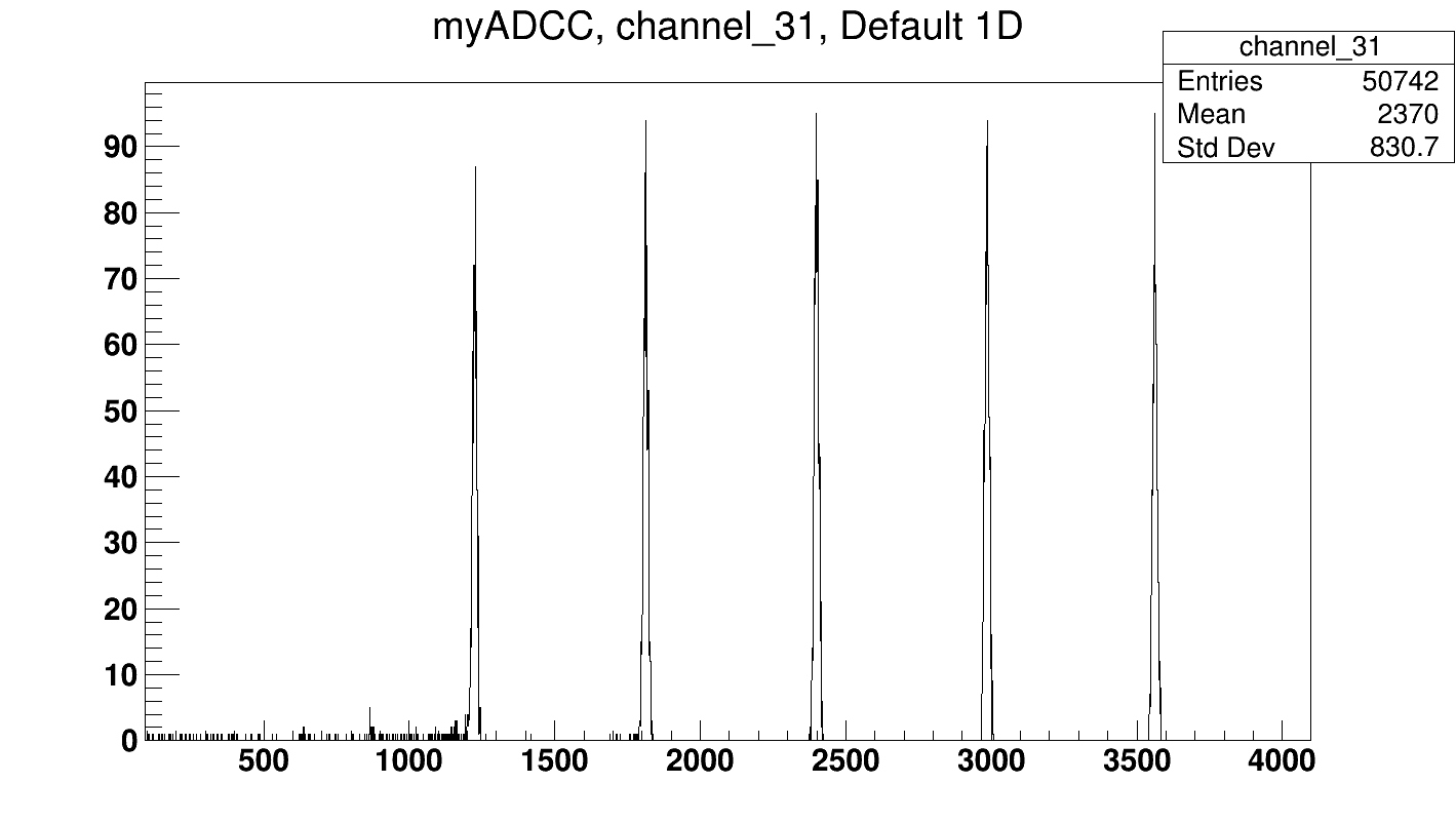
After the alpha source calibration of the S2 (See eLog entry #21) we decided to perform a pulser walkthrough for the pin diode on ADC 6 CH 31.
The pulser was only connected to the pin diode preamp to ensure it wasnt being split.
Note: Since the pulser is still being 50 ohm terminated the amplitude setting is divided by 2 regardless of any signal splitting. Example: Setting a pulse height of 1.0V on the PB-5 corresponds to an output pulse height of 0.5V.
The pulser settings for this walkthrough were:
Fall Time = 100us
Rate = 10.00Hz
Delay = 250ns
Ampl = varied 1.0V -> 0.25V
Pol = POS
Pulse Top = Tail
Atten = 1X
PB-5 Pulse = ON
CLAMP = OFF
For this test we also needed to change the Delay Amp 1457 delay setting from 1us to 3us to ensure pulses were occuring after the DAQ OR trigger
I collected a DAQ run for the following pulse amplitude settings:
0.1V, 0.15V, 0.2V, 0.25V, and 0.3V
We also attempted 0.05V and 0.07V but were unable to see a clearly defined peak in the spectrum - likely caused by the high level of noise from the CFD we see at the low ADC channels. This should be better optimised at the start of the next shifts.
The save name for this pulser walkthrough is: Remote_Objs/RData_1/180223180747
See attached "180323_PulserWalk_PinDiode_ADC6CH31.png" for the pulser walkthrough spectrum. |
| Attachment 1: 180223_PulserWalk_PinDiode_ADC6CH31.png
|
|
|
45
|
Wed Nov 21 09:09:41 2018 |
Thomas Chillery, Marialuisa Aliotta, Carlo Bruno, Lizeth Morales, David Rapagni | Mounting Detectors / Continuing Electronic Chain Tests | On 20/11/2018:
At 9:00 we walked into the lab, David R reported he found all the pumps OFF. A thunderstorm occurred overnight causing a power outage.
Last night we had switched off the electronics (Preamp power, RAL amp rack, and NIM bin).
This morning we determined everything was ok to switch on.
Using eLog entries #26 and #27 as reference we mounted the following detectors and foils:
- Far S2: 2323-18, 12um mylar
- Near S2: 2623-26, 12um mylar
- Silicon pin diode: 0.9um mylar
The pin diode used in previous tests had something deposited (fingerprint?) on the crystal, so we replaced this with a new clean diode.
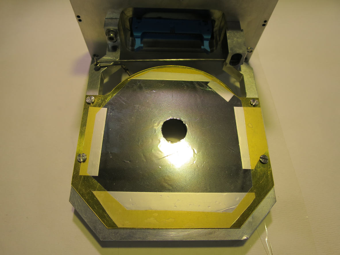
We mounted the detectors and foils inside the chamber, the target ladder was kept in its configuration with all blank frames (see eLog entry # 41). See attached picture 1 for the 12um mylar mounted in front of the far S2.
We mounted preamp I on the near position and preamp II on the far position, as will be used during the measurement.
We sealed the chamber to ensure it was light tight.
We applied pramp power, expected currents were drawn.
With no S2 bias we see high noise on the majority of the RAL amplifiers for both preamps I and II. We switched off the lab lighting and found the chamber was indeed light tight - there were no observable changes in noise.
We discovered CH2 of the Silena HV module does not supply bias.
We applied -10V bias to both S2's. The far S2 is biased using CH1 and the near S2 is biased using CH4 of the HV module. The leakage currents read: Far S2 = 0.35uA, Near S2 = 1.81uA.
With bias RAL X CH 0 baseline RMS noise ~ 55mV.
We biased the pin diode with its operating -70V using CH3 of the HV module, leak I = 0.01uA.
We decided to switch off all biases and prepare for tests under vacuum with an alpha source.
CH1 and 4 of the HV module were set to -130V ready for the S2's
|
| Attachment 1: IMG_3209.JPG
|
|
|
15
|
Thu Feb 22 10:40:49 2018 |
Thomas Chillery, Raffaele Buompane, David Rapagnani, Lucio Gialanella | Measurement / Test - 3.0MeV 7Li on CH2 Target VII | On 21/02/2018 after beam tuning and pumping down at 18:07 the pressures read Up = 1.2e-5mBar, Down = 3.2e-5mBar. We were happy to power the detectors and try to observe spectra from beam in both the S2 and pin diode.
Whilst waiting for the turbos to spin up the Pin diode was daisy chained with the +ve pulser, +15V, and -15V preamp power cables used with EDI Preamp 2 for the S2.
Channel 3 of the Silena Quad Power Supply was set to -70V ready for the diode.
The S2 bias was ramped to -130.3V, leak current = 1.19uA. The Pin diode bias was ramped to -70V, leak current = 0.01uA.
The preamp power was switched on, +15V read current 0.8A, -15V read current 0.4A, as expected.
The pin diode output was split between an Ortec 571 Amplifier and channel 2 of a Quad TFA.
The unipolar output of the Ortec 571 Amplifier was sent to a Delay Amp 1457. The Delay Amp output was sent to ADC 6 Channel 31.
The Quad TFA output was sent to channel 4 of a Quad CFD. The CFD output was sent to the Lecroy 622 module and setup as an OR with the S2 strips. This OR is sent to the DAQ trigger.
We mounted the preamp box cover. The grounding cable for the ribbon signal cables was attached to the box. We confirmed the grounding of these ribbon cables with a voltmeter.
Now with no beam the DAQ trigger rate ~ 60Hz. This suggests the ~6kHz rate seen before is noise from the previously exposed preamp, note the downstream turbo is very close (a couple centimeters) to this preamp.
To double check the tuning was still ok we sent the 7Li beam to FC-0 = 48pA.
We decided to close the GSI slits located before the quadrupole and slowly open these to their values in eLog entry #14. We closing the left and right slits had no effect on reducing beam current, so we kept these positioned at 5.5mm and 1.5mm respectively. The up slit was already 0.0mm.
Slowly opening the down slit we saw the following:
| GSI Down Slit Position (mm) |
DAQ Trigger Rate (Hz) |
| 0.0 |
60 |
| 0.1 |
110 |
| 0.2 |
180 |
| 0.3 |
250 |
| 0.4 |
250 |
| 0.5 |
380 |
| 0.6 |
450 |
| 0.7 |
550 |
| 0.8 |
675 |
| 0.9 |
750 |
| 1.0 |
850 |
| 1.1 |
925 |
| 1.2 |
850 |
| 1.3 |
1000 |
| 1.4 |
1100 |
| 1.5 |
1100 |
| 1.6 |
1050 |
| 1.7 |
1100 |
| 2.0 |
1300 |
| 2.2 |
1350 |
| 2.5 |
1300 |
| 3.0 |
1300 |
| 3.5 |
1400 |
| 4.0 |
1600 |
| 5.0 |
1600 |
| 5.5 |
1600 |
We saw on the backscattered diode counts at channels 50 -> 400, even when increasing the Ortec 571 Amplifier gain to 1K and the fine gain to maximum.
We checked the faraday cup upstream from the bending magnet, FC-4 = 100pA.
We also checked the faraday cup just upstream from the chamber, FC-0 = 53 pA.
The Ortec 571 Amplifier settings (for pin diode) were:
Fine gain = Max
Course gain = 1K
Shaping time = 0.5us
Input = Neg
BLR AUTO ON
Uni Output taken with Out setting
The Ortec 935 Quad CFD CH4 threshold was = 175mV
At 20:50 we sent 3.0 MeV of 7Li beam onto CH2 930ug/cm2 Target VII. We started the DAQ whilst writing to disk.
The DAQ dead time ~ 3%, Trigger rate ~ 1500 Hz, Event Mult. = 6.2.
The save path and name: /Remote_Objs/RData_1/180221205456
It became apparent within the first 1/2 hour that the trigger rate (1500 Hz) is almost entirely from the pin diode.
At 22:10 we stopped the DAQ data collection, run time = 01:19:46, dead time = 4%, # of Good Events = 7180956.
We checked the current on FC-0 = 53 pA.
The beam voltage ~1.2730 MV.
Checking the detectors: The pin diode voltage = -70V, leak I = 0.00uA. The S2 bias = -130.3V, leak I = 1.46uA. Both detectors were switched off for the night.
At 22:18 the pressures in the chamber are:
TPU1 = 3.4e-6mBar
TPU2 = 7.5e-7mBar
TPD1 = 1.5e-6mBar
TPD2 = 1.8e-6mBar
CHUP = 6.1e-6mBar (also referred to as Up)
CHDW = 1.6e-5mBar (also referred to as Down)
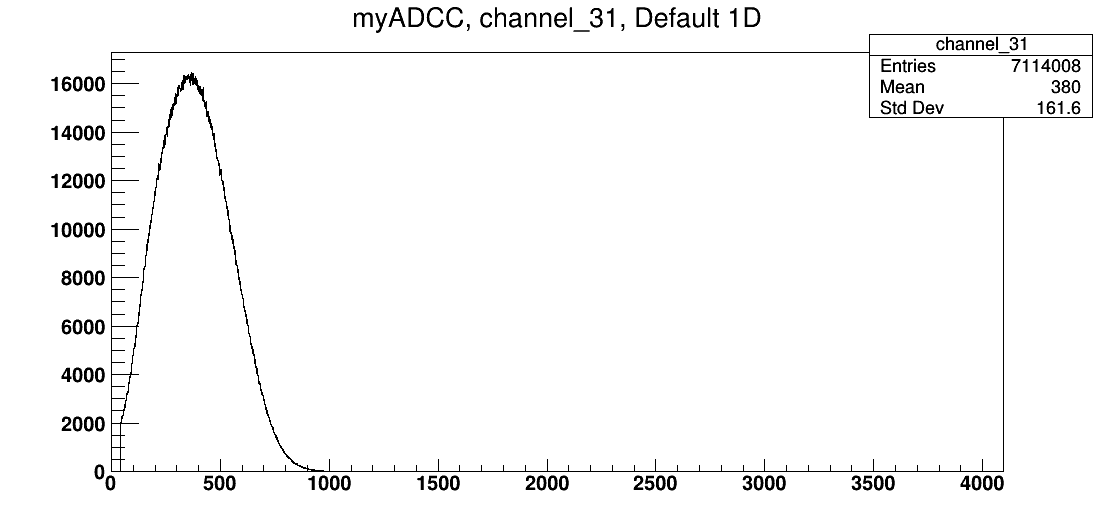
See attached "180221_PinDiode.png" for the pin diode spectrum after the run. In the morning of 22/02/2018 we realised this was just amplified noise.
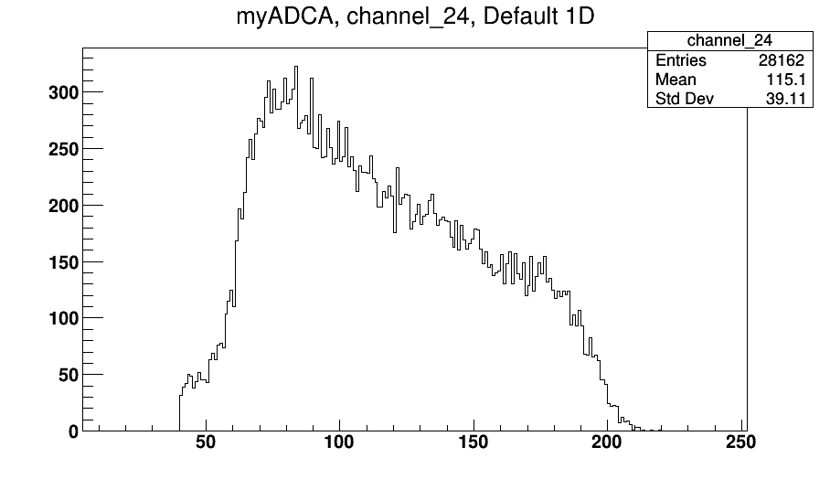
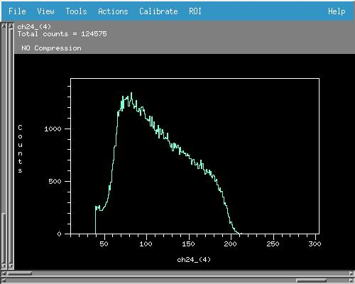
See attached "180221_S2BackStrip_ADC4CH24.png" for a sample spectrum of one of the S2 back strips
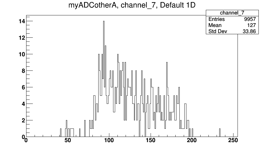
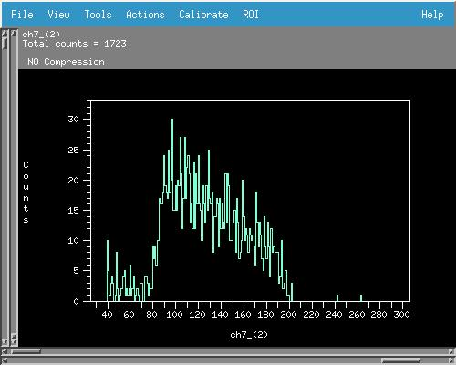
See attached "180221_S2BackStrip_ADC2CH7.png" for a sample spectrum of one of the S2 front strips |
| Attachment 1: 180221_PinDiode.png
|
|
| Attachment 2: 180221_S2BackStrip_ADC4CH24.png
|
|
| Attachment 3: 180221_S2FrontStrip_ADC2CH7.png
|
|
|
20
|
Sun Feb 25 15:59:38 2018 |
Thomas Chillery, Lizeth Morales, Raffaele Buompane, David Rapagnani, Lucio Gialanella | Measurement - 3.45MeV 7Li on CH2 Target III | On 23/02/2018 at 13:49 we started the DAQ in list mode.
After starting the DAQ we sent the 3.45MeV 7Li beam onto the CH2 930ug/cm2 target III.
The trigger rate ~ 2kHz, event multiplicity = 6.1, dead time ~ 9%.
The DAQ save file is: /Remote_Objs/RData_1/180223135345
Checking the ADC rate histograms:
- ADC 2 Channels 0->7 Rate ~ 1e3 (channels 0 and 5 still disabled)
- ADC 2 Channel 8 dead
- ADC 2 Channels 9->31 Rate ~ 1e4 - 1e5
- ADC 4 Channels 0->15 Rate ~ 1e3
- ADC 4 Channels 16 -> 29 and 31 Rate ~ 1e4 - 1e5
- ADC 4 Channel 30 dead
- ADC 6 Channel 31 Rate ~ 8e5
Picking an S2 backstrip at random we found a proton detection rate ~ 100Hz, no high rate beam scatters were seen, as expected from the thick target. We decided to run for several hours.
We performed occasional checks during the run:
| Runtime (hh:mm:ss) |
ADC # / Ch # |
Area in region |
Ratio to pin diode (ADC 6) |
| 01:01:00 |
2/20 |
183850 |
61.47 |
| 6/31 |
2991 |
|
| 4/24 |
262051 |
87.61 |
| 01:30:37 |
2/20 |
269255 |
61.49 |
| 6/31 |
4380 |
|
| 4/24 |
377251 |
82.94 |
| 02:03:22 |
2/20 |
362581 |
58.07 |
| 6/31 |
5987 |
|
| 4/24 |
501628 |
77.40 |
| 02:30:34 |
2/20 |
437224 |
57.86 |
| 6/31 |
7277 |
|
| 4/24 |
600118 |
76.35 |
| 03:19:02 |
2/20 |
561345 |
53.80 |
| 6/31 |
9584 |
|
| 4/24 |
765584 |
71.72
|
Where the area regions used (in channels) for each ADC Channel are:
ADC 2 Ch 20: 0->552
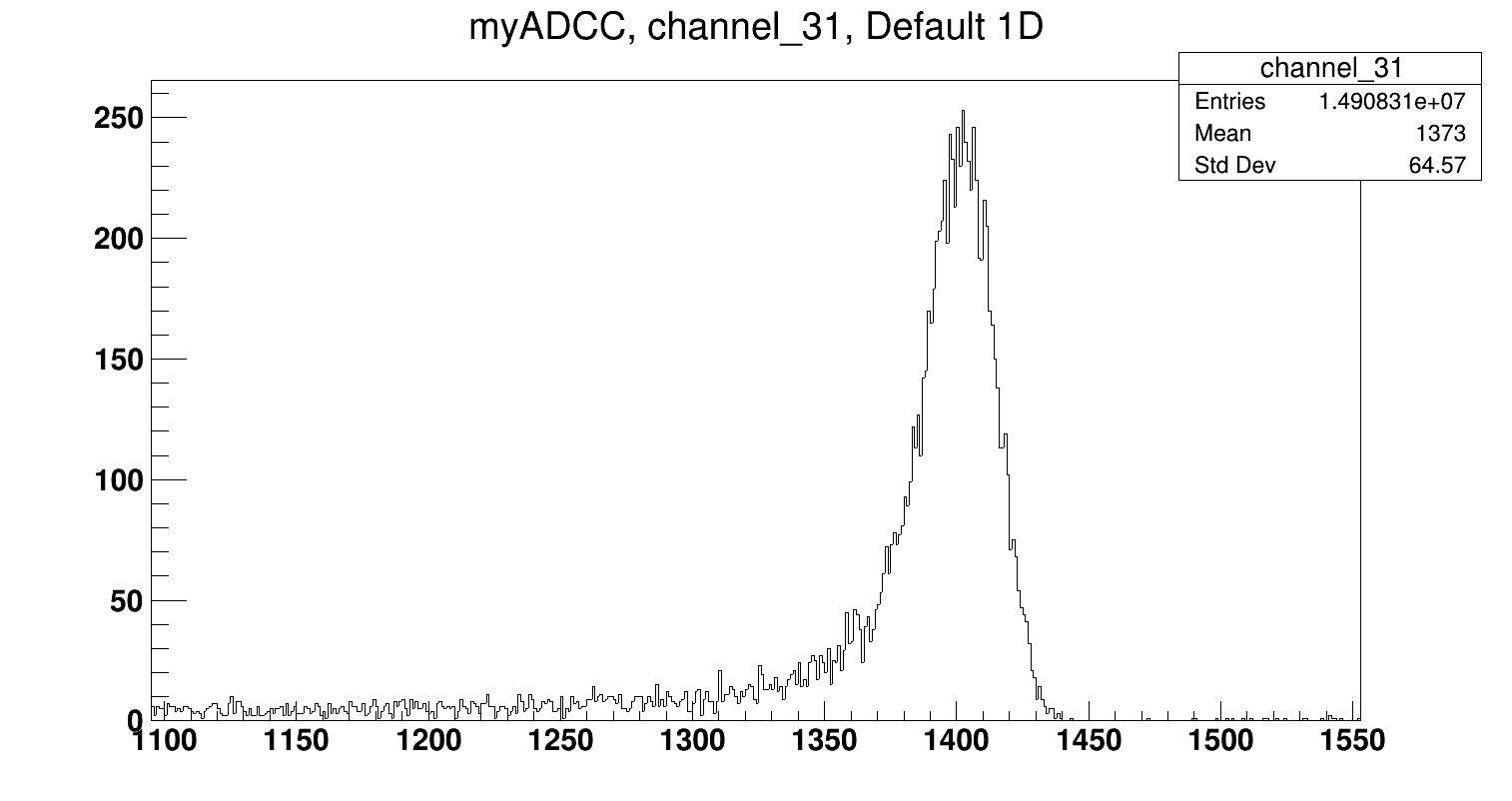
ADC 6 Ch 31: 1302->1475
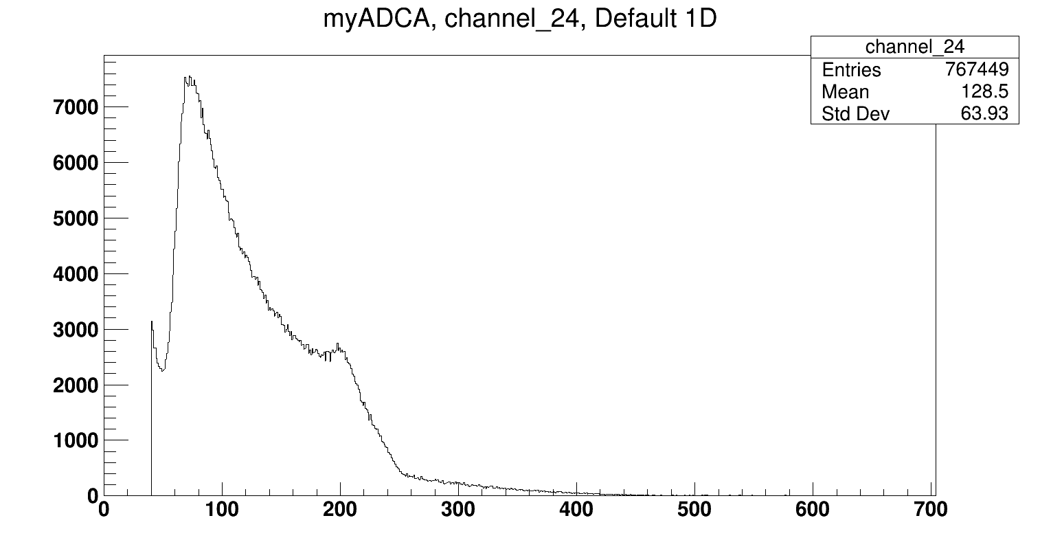
ADC 4 Ch 24: 20 ->549
The ratios use the number of counts since the previous check. The ratios are decreasing as expected, because this indicates that fewer protons are being detected during the irradiation time.
At 17:08 the DAQ was stopped at runtime 03:19:02
The DAQ monitor dead time ~ 5%. Event multiplicity ~ 6.0, # Good events = 23917715.
We checked the beam current before the chamber, FC-E0 ~ 190pA.
See attached "180223_S2FrontStrip_ADC2CH20.png" for sample front S2 strip spectrum
See attached "180223_S2BackStrip_ADC4CH24.png" for sample back S2 strip spectrum
See attached "180223_PinDiode_ADC6CH31.png" for sample pin diode spectrum |
| Attachment 1: 180223_S2FrontStrip_ADC2CH20.png
|

|
| Attachment 2: 180223_S2BackStrip_ADC4CH24.png
|
|
| Attachment 3: 180223_PinDiode_ADC6CH31.png
|
|
|
17
|
Thu Feb 22 18:04:12 2018 |
Thomas Chillery, Raffaele Buompane, David Rapagnani, Lucio Gialanella | Measurement - 3.0MeV 7Li on CH2 Target VII | Yesterday (21st) night we saw this low channel, high rate (1500Hz) noise on the diode spectrum - see eLog entry #15.
This morning the S2 bias was ramped to -130.3V, leak I = 1.43uA. Diode bias ramped to -70.0V, leak I = 0.01uA.
Starting the DAQ with no beam, the trigger rate is ~250 Hz, with most triggers coming from the diode. Inspecting with the oscilloscope we find a very high noise of ~300mV. The amplifier course gain = 1K.
Lowering the course gain to 200 we decided to try sending beam on target VII and check the diode output on the oscilloscope. I was able to see some signals at ~3V, with very low rate ~0.1Hz
I checked the rutherford scattering rate using the Nuclear_Reaction-master.xlsx excel file, sheet "Rutherford Scattering" columns BH and BP. See attached.
With the current collimator radius = 0.5mm, at our scattering angle 152 degrees, we find an expected rate 2.72e-3 particles per second.
We decided to remove the diode collimator, for the 10X10mm diode this would give an expected rate 0.272 particles per second. This is still not ideal, and before the next shifts we should optimise the position of the diode to improve the rates. This is for a beam current ~40pA, so we would benefit from higher beam current too. A rate of 5 - 10 particles per second would be nice. For now we stuck with the current situation.
At 10:52 the S2 and diode biases were switched off. The preamp power was also switched off. The turbos were also switched off. By 11:48 I saw the turbos had stopped spinning and started venting the chamber.
Once the chamber was vented we managed to remove the central lid without needing to remove the S2 preamp box on the downstream lid.
The 1mm diameter collimator was removed from the diode, this completely destroyed the 0.9um mylar in the process. Next shifts we will use a metal plate to glue the mylar in place, avoiding this issue. For now we left no mylar in front of the diode, because this will not be useful until running 7Be beam.
We also decided to remount the alpha source, allowing us to check the diode is functioning as expected. The target ladder configuration is as follows:
| Position |
Target |
| 1 |
Blank 3mm |
| 2 |
No Target |
| 3 |
CH2 VII |
| 4 |
CH2 III |
| 5 |
CH2 VI |
| 6 |
No Target |
| 7 |
Alpha source facing upstream |
After removing the diode collimator the central lid was remounted and at 12:50 the roughing pumps started. At 13:12 the turbos were started.
By 13:53 the pressures read CHUP = 1.2e-5mBar and CHDW = 3.3e-5mBar.
We switched on the preamp power. The S2 bias was ramped to V = -130.3V, leak I = 1.25uA. The diode bias was ramped to -70.0V, leak I = 0.01uA.
The target ladder was moved to position 7 (5.019mm), centering the alpha source in the beam axis and pointing upstream.
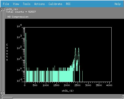
We were able to see the two highest intensity alpha peaks in the pin diode spectrum (ADC6 CH31) - so the diode is certainly working
At 14:06 we started an alpha calibration run for the pin diode.We collected data for a preset time 900 seconds. The trigger rate ~80Hz, Event Mult. = 3.0, dead time = 0%.
The save name is: /Remote_Objs/RData_1/180222141134
See attachment PinDiode_AlphaSpectra.jpg for a sample spectrum
The Ortec 871 Amplifier Settings were:
Fine gain = Max
Course gain = 50
Shaping time = 0.5us
BLR Auto On
The Delay Amp 1457 settings were:
Delay: 1us
Range: 10V
Polarity: Pos
At 14:21 the DAQ stopped, # good events = 61406.
Now we were ready to proceed with a beam measurement.
The target ladder was moved to position 3, 65.000mm, target: CH2 930ug/cm2 VII
We still see some alphas from the source, these are 5.1->5.5MeV, and from the kinematics we expect the beam scatters to be ~2.9MeV so there should be no overlap in energy.
I disconnected the pulser from the pin diode (it was set to too high an amplitude to appear on the alpha spectrum) and switched it ON for the S2 front strips. The pulser rate was changed from 10Hz to 2Hz. (Set to 10Hz when diagnosing pin diode)
With no beam trigger rate ~85Hz, event mult. ~ 8.0
We checked the beam at FC-E0, just upstream from chamber, = 45pA
We bombarded CH2 VII with 3.0MeV 7Li beam, trigger rate ~700Hz.
The pin diode rate for backscattered beam was very low, but we do see some counts at channel ~1300, which is expected.
We decided to run for 1 hour and see the rates.
15:00 DAQ started for 3.0MeV 7Li on CH2 930 ug/cm2 target VII
Save file: Remote_Objs/RData_1/180222150540
Trigger rate ~ 550Hz, Event Mult. ~ 6.2, dead time ~4%
Note: from previous tuning and running yesterday (21st) I estimate beam has already bombarded target VII for ~3 hours before starting this run.
At run time = 01:01:09 we have the following areas:
ADC 6 CH31 (pin diode) area between channels 1159->1268 = 285
ADC 4 CH24 (S2 back strip) total area = 7353
ADC 2 CH 3 (front S2 strip) total area = 21647 (2Hz pulser connected)
Ratio of back strip to diode = 76.0
We decided to collect data until 20:00 giving us ~5 hours of data at 3.0MeV.
At DAQ runtime = 03:03:09 we have the following areas:
ADC 6 CH31 (pin diode) area between channels 1159->1268 = 911
ADC 4 CH24 (S2 back strip) total area = 66704
ADC 2 CH 3 (front S2 strip) total area = 22335 (2Hz pulser connected)
ADC 2 CH 7 (front S2 strip) total area = 22734 (2Hz pulser connected) - more statistics than ADC2 channel 3, continued monitoring this channel instead of channel 3
Ratio of back strip to diode = 73.2
Ratio of last ~2 hours runtime = 71.0, so target is degrading
At 19:25 we decided to go to dinner and leave the setup to collect data.
At this time CHUP = 5.4e-6mBar, CHDW = 1.4e-5mBar. S2 bias = -130.3V, leak I = 1.71uA. Diode bias = -70.1V, leak I = 0.00uA.
At 20:50 we returned from dinner. The DAQ was manually stopped.
DAQ monitor:
Run time = 05:49:09
Event mult. = 6.2
Dead time =7%
# good events = 34296773
At the end of data collection the areas are:
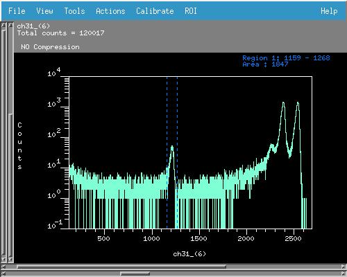
ADC 6 CH31 (pin diode) area between channels 1159->1268 = 1847
ADC 4 CH24 (S2 back strip) total area = 124876
ADC 2 CH 7 (front S2 strip) total area = 43334 (2Hz pulser connected)
Ratio of back strip to diode = 67.6
Ratio of last ~ 3hours = 62.1 - so target is still degrading
The S2 bias = -130.3V, leak I = 1.75uA. S2 Bias ramped OFF
The diode bias = -70.1V, leak I = 0.00uA. Diode bias ramped OFF
Preamp power OFF
At 20:53 the pressures read:
TPU1 = 2.5e-6mBar
TPU2 = 6.4e-7mBar
TPD1 = 1.6e-6mBar
TPD2 = 1.6e-6mBar
CHUP = 5.2e-6mBar
CHDW = 1.3e-5mBar
See attached 180222_diode.jpg for the final diode spectrum.
See attached 180222_ADC4CH24.jpg for the final S2 back strip spectrum
See attached 180222_ADC2CH7.jpg for the final S2 front strip spectrum |
| Attachment 1: Nuclear_Reaction-master.xlsx
|
| Attachment 2: 180222_diode.jpg
|
|
| Attachment 3: 180222_ADC4CH24.jpg
|
|
| Attachment 4: 180222_ADC2CH7.jpg
|
|
| Attachment 5: PinDiode_AlphaSpectra.jpg
|
|
|
77
|
Wed Sep 18 14:01:13 2019 |
Thomas Chillery | Logbook Spreadsheet | See attached for the logbook |
| Attachment 1: 181123_Logbook.xls
|
|
66
|
Mon Dec 3 17:40:51 2018 |
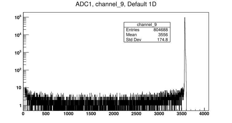
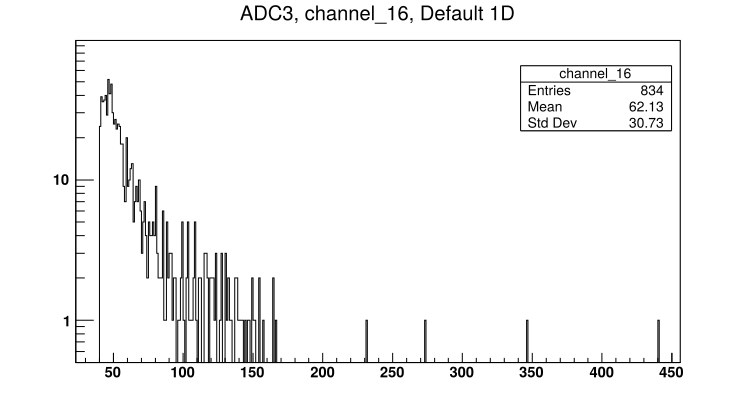
Thomas Chillery, Carlo Bruno, Raffaele Buompane | Lab background | On 27/11/2018:
Run # 181127200709
- Run time: 46329s
- Pulser ON, as before
- No target
- No beam
- Lab background
- DT ~ 12%
- See attached picture 1 for sample far S2 front strip spectrum. See attached picture 2 for diode spectrum.
At 20:00:
Far S2 bias = -130.0V, leak I = 1.52uA. Diode bias = -70.1V, leak I = 0.00uA. Preamps drawing correct current.
Pressures (mBar):
- TPU1 = 7.0e-6
- TPU2 = 1.9e-6
- TPD1 = 1.5e-6
- TPD2 = 1.7e-6
- CHUP = Sensor Off
- CHDW = No Sensor
Rate meter ~ 5000Hz
On 28/11/2018:
At 8:55 Far S2 bias = -130.0V, leak I = 1.67uA. Diode bias = -70.1V, leak I = 0.00uA.
Rate meter ~ 4100Hz
Pressures (mBar):
- TPU1 = 8.5e-7
- TPU2 = 6.3e-7
- TPD1 = 7.5e-7
- TPD2 = 6.5e-7
- CHUP = Sensor Off
- CHDW No Sensor
Stopped lab background run |
| Attachment 1: 181127200709_ADC1_Ch9.png
|
|
| Attachment 2: 181127200709_ADC3_Ch16.png
|
|
|