| ID |
Date |
Author |
Subject |
|
744
|
Thu Nov 13 10:14:50 2025 |
JB, MP | Noise conditions after removal of bPlast cabling |
JB has removed unnecessary cables and items from the snout and platform:
- the bPlast cables and booster boards were removed
- crate below the AIDA frame was disconnected from the power supply
- BB7 cables were removed
- power supply for the booster boards was removed
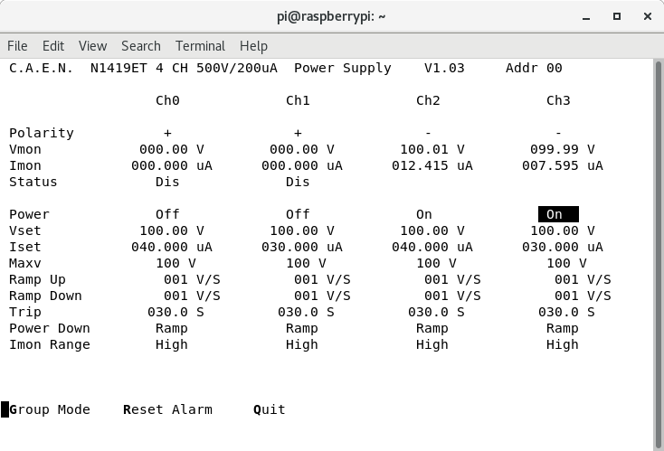
We switch on the system and check the noise conditions.
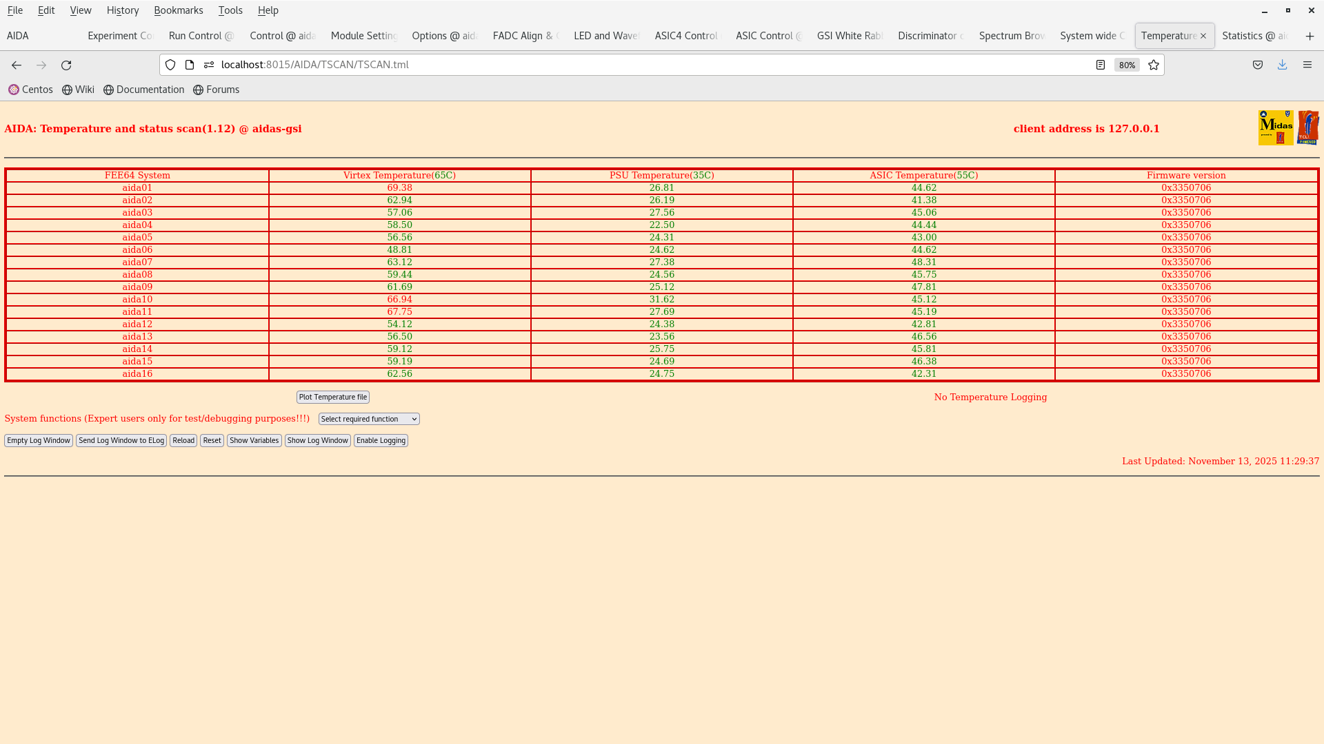
We started up. BIAS OK. TEMPS OK.
Thresholds initially set to 100 keV.
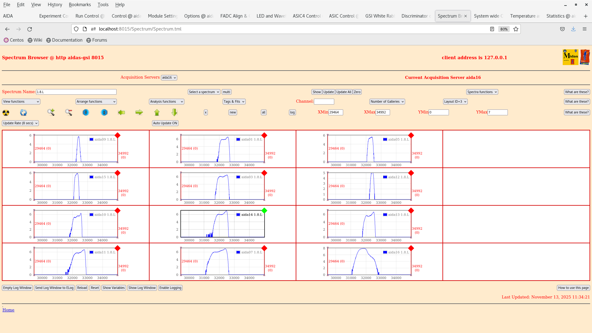
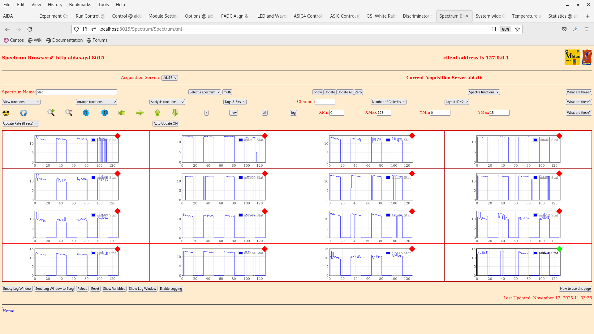
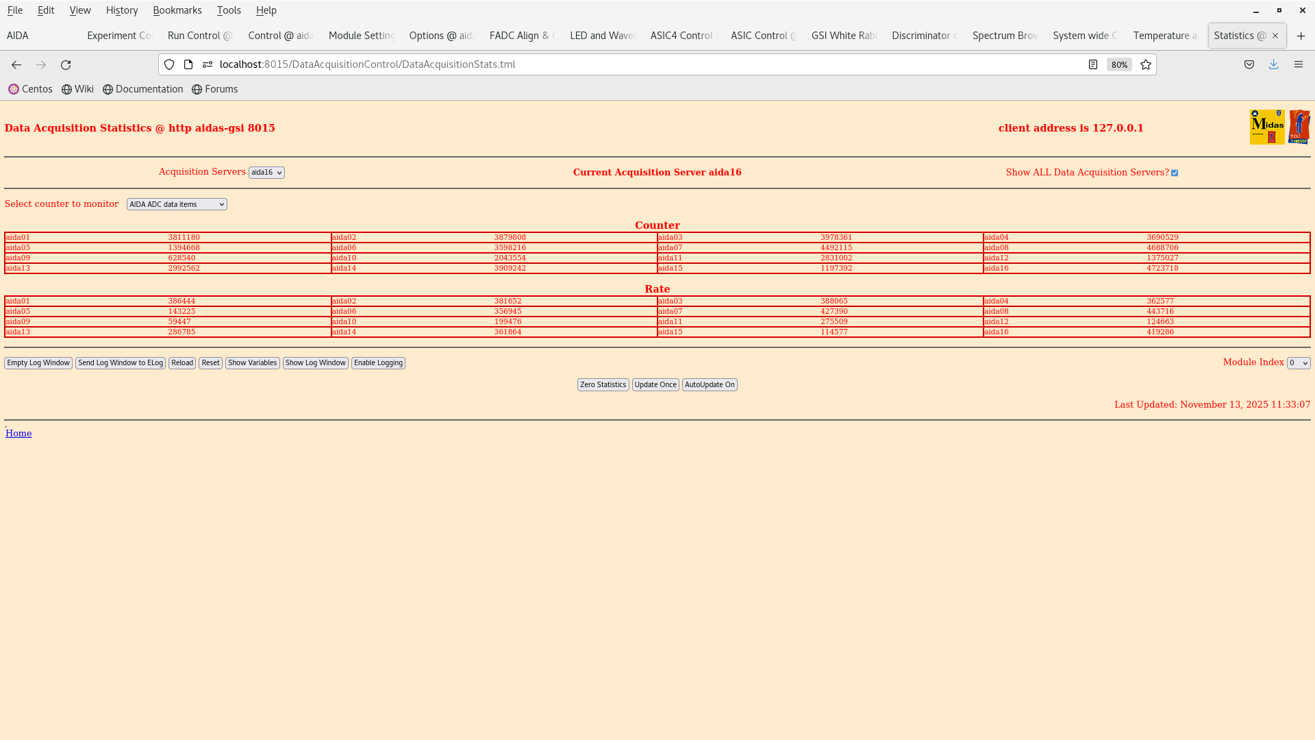
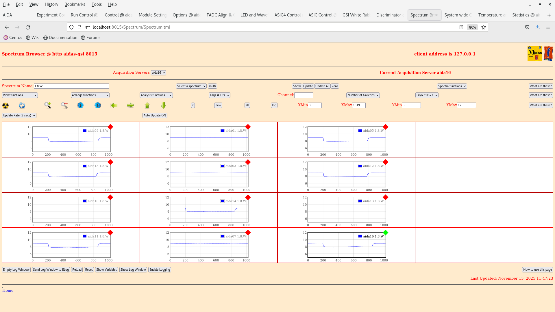
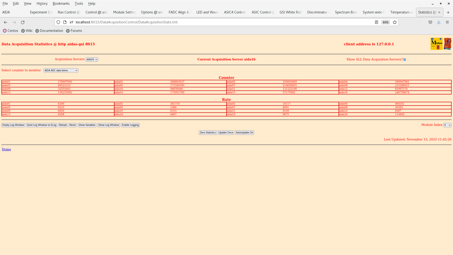
Rates in all FEEs are > 200 kHZ. Attachment 6.
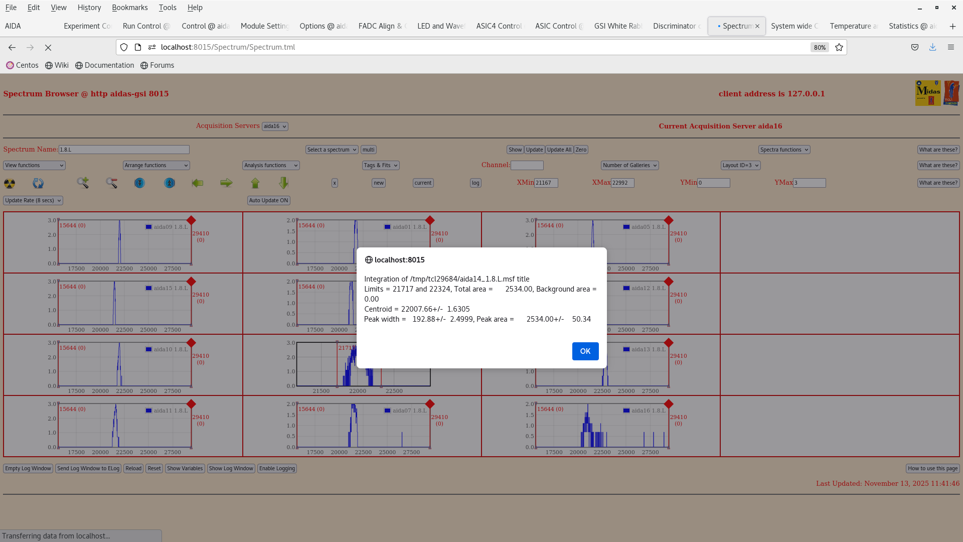
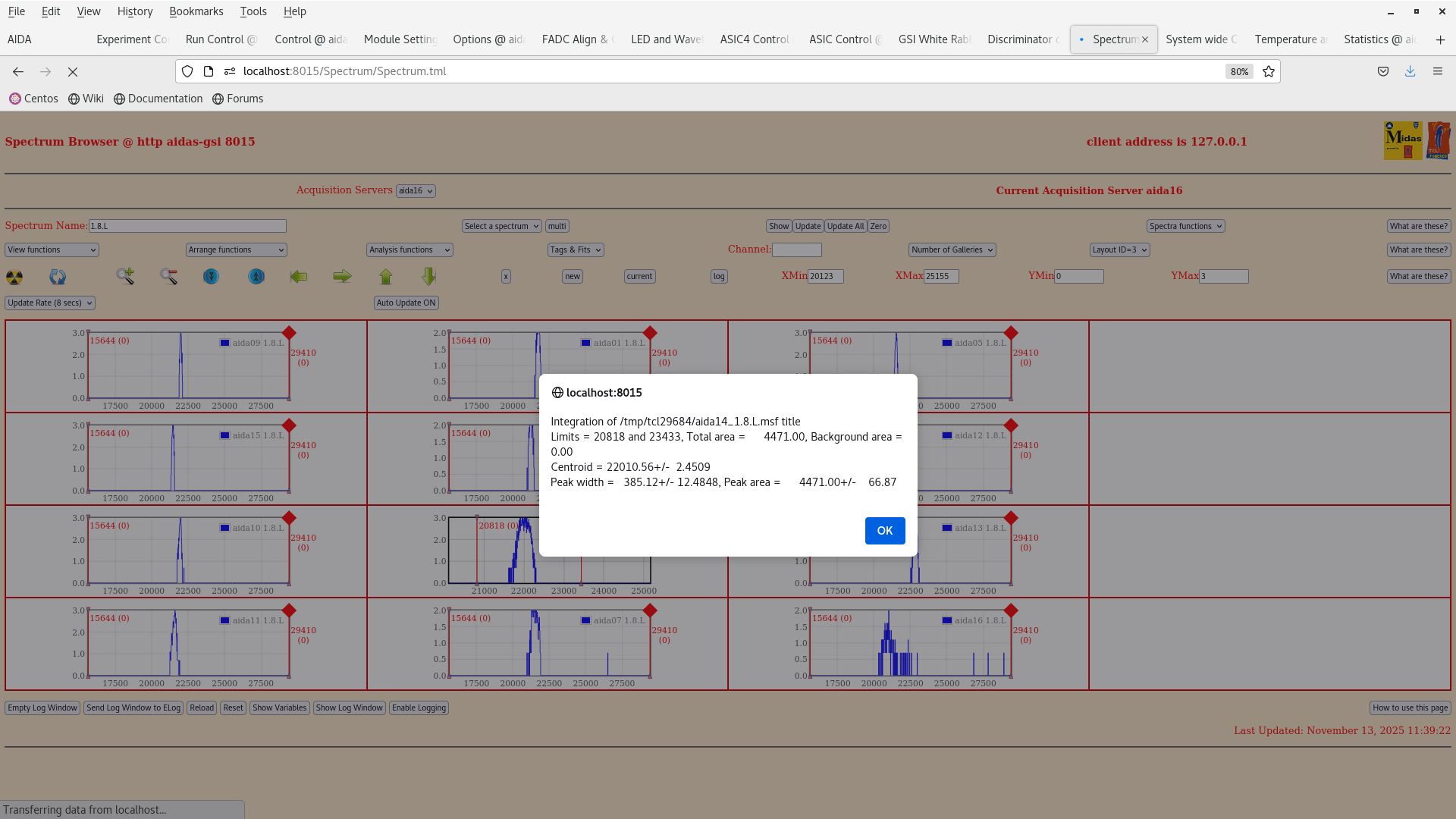
We then checked the pulser peak widths in aida14. --> 192 channels with 1 V 1x attenuation. at 700 keV threshold (attachment 3). At 100 keV threshold the peak width was significantly higher!!! ---> 385 channels (attachment 2)
We checked the rates in the FEEs with the 700 keV thresholds (attachment 11).
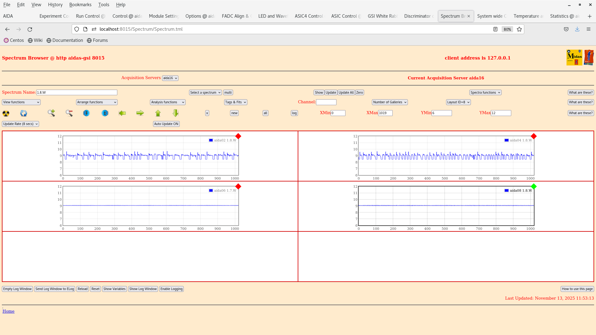
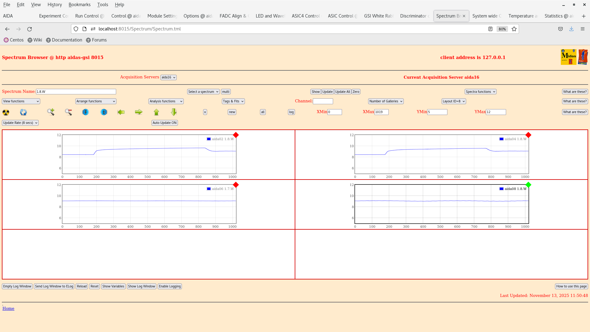
Furthermore, we checked the constant noise that appears to be present in the y FEEs aida02,04,06,08. This can be seen in attachment 8 and has been noted in previous elogs https://elog.ph.ed.ac.uk/DESPEC/727
Info on current status of ion catcher: vacuum system is ON, electronics is also on (RF ~2MHz) on the side opposite to the DESPEC setup |
| Attachment 1: Screenshot_from_2025-11-13_11-17-27.png
|
|
| Attachment 2: Screenshot_from_2025-11-13_11-41-48.png
|
|
| Attachment 3: Screenshot_from_2025-11-13_11-39-30.png
|
|
| Attachment 4: Screenshot_from_2025-11-13_11-34-29.png
|
|
| Attachment 5: Screenshot_from_2025-11-13_11-33-38.png
|
|
| Attachment 6: Screenshot_from_2025-11-13_11-33-13.png
|
|
| Attachment 7: Screenshot_from_2025-11-13_11-29-41.png
|
|
| Attachment 8: Screenshot_from_2025-11-13_11-53-18.png
|
|
| Attachment 9: Screenshot_from_2025-11-13_11-50-53.png
|
|
| Attachment 10: Screenshot_from_2025-11-13_11-47-30.png
|
|
| Attachment 11: Screenshot_from_2025-11-13_11-45-30.png
|
|
|
681
|
Wed Jan 8 10:08:29 2025 |
JB, GB, SD, MP, CC, JG | AIDA noise test with platform in position |
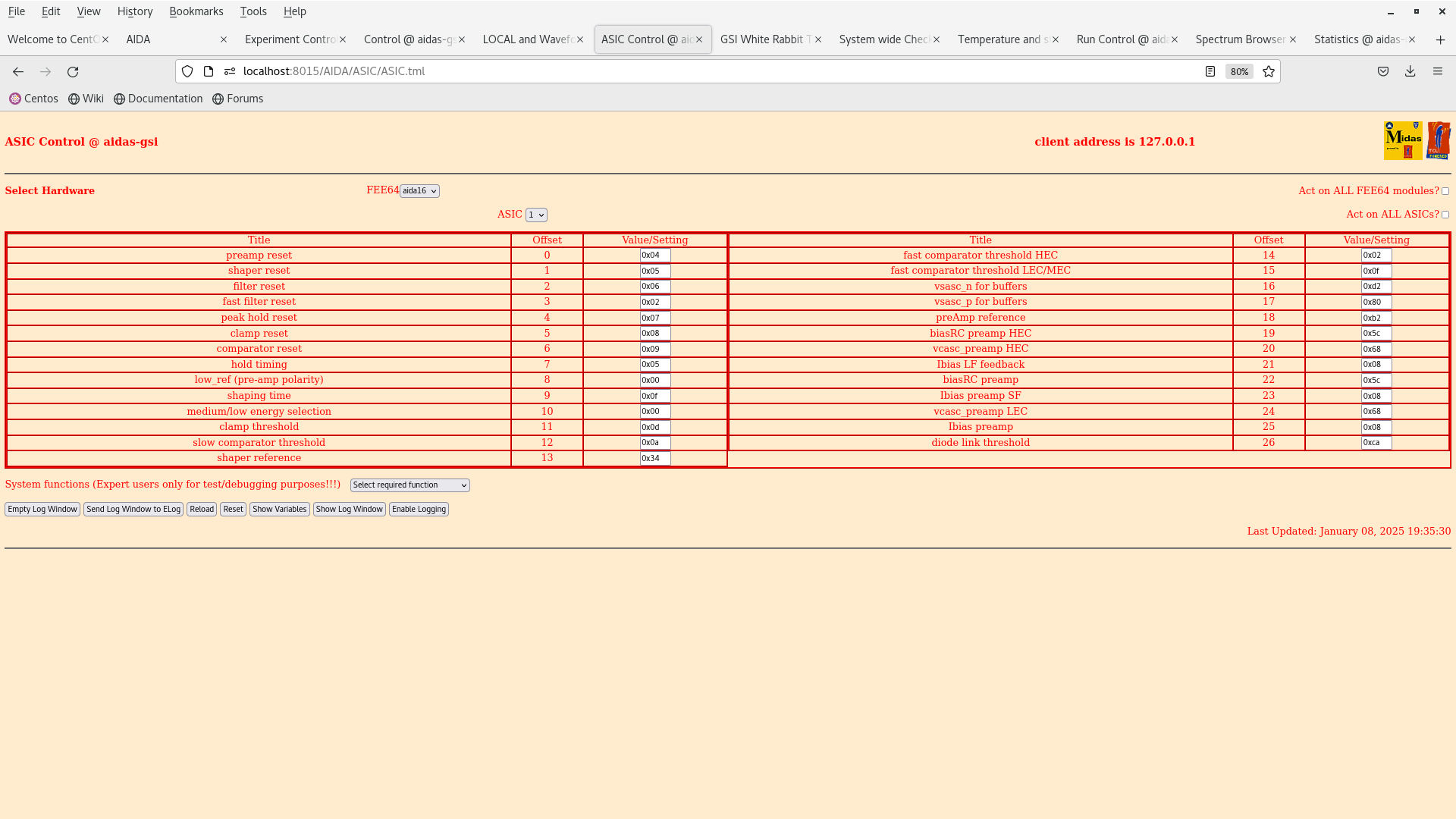
Yesterday we spent time essentially performing a dry run to get AIDA DAQ and bPlast into the time sorter, there were some issues with the AIDA mbs PC x86l-119 which was related to some boot issue, it was booting to a newer version of debian while the Relay for AIDA to MBS is on an older version (scratch) (the machine is quite old). We spent a bit of time getting the thresholds correct for each of the ASICs. In the end we just elected to have a blanket level of 0x0f for all of the ASICs when we removed the pulser.
Last night we left the setup with the following thresholds on all of the FEEs to collect data. 681/1. The pulser was also turned off and the 22Na source was moved close to the snout.
This morning c. 9:25 we returned and checked the temperatures, HV and statistics and everything seems to be ok. The only problem was that the timesorter has crashed this morning at 8 am. |
| Attachment 1: Screenshot_from_2025-01-09_09-32-08.png
|
|
| Attachment 2: Screenshot_from_2025-01-09_09-35-11.png
|
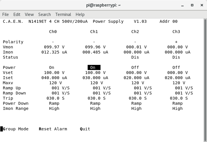
|
| Attachment 3: Screenshot_from_2025-01-09_09-32-20.png
|
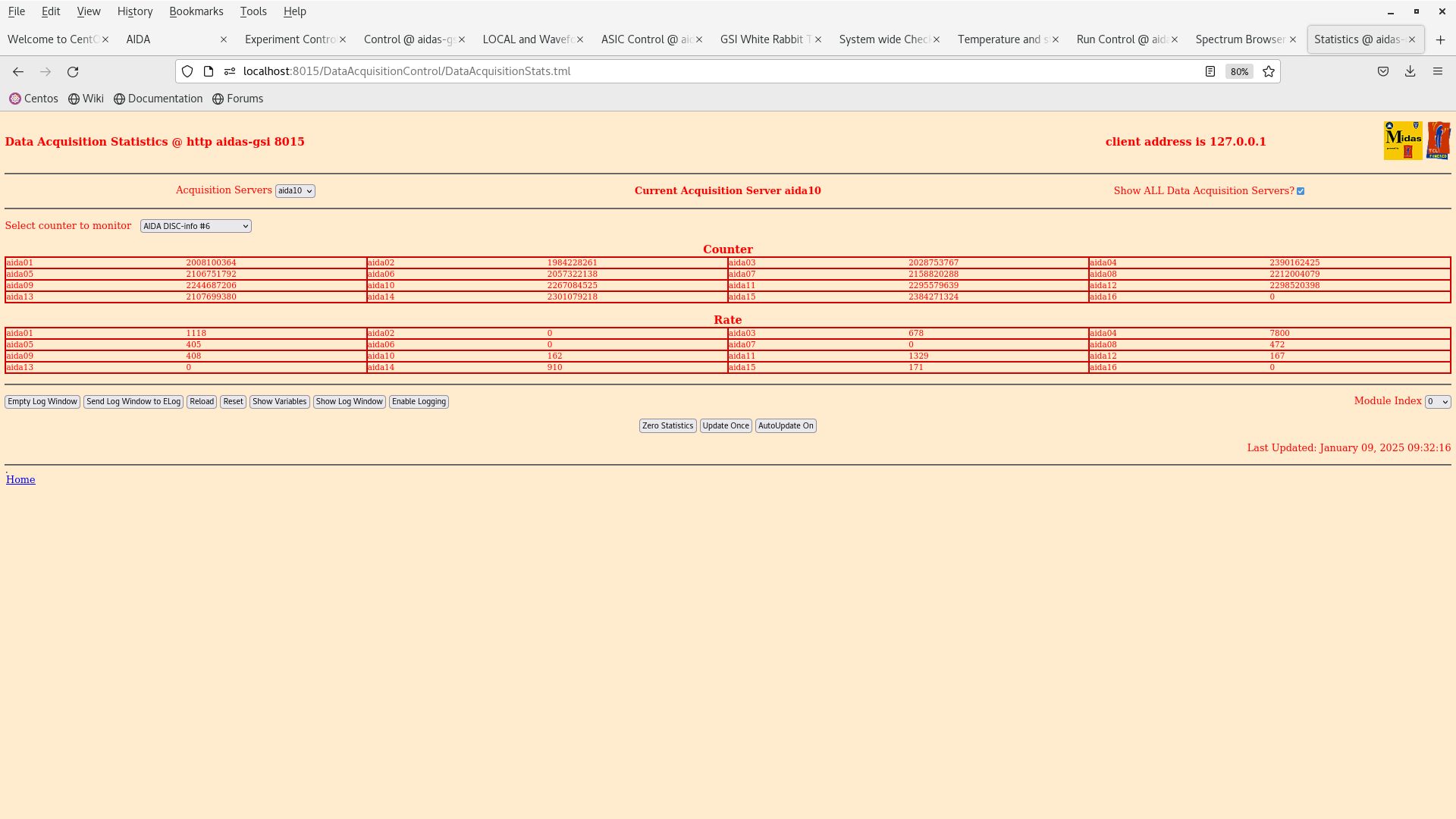
|
| Attachment 4: Screenshot_from_2025-01-09_09-31-58.png
|
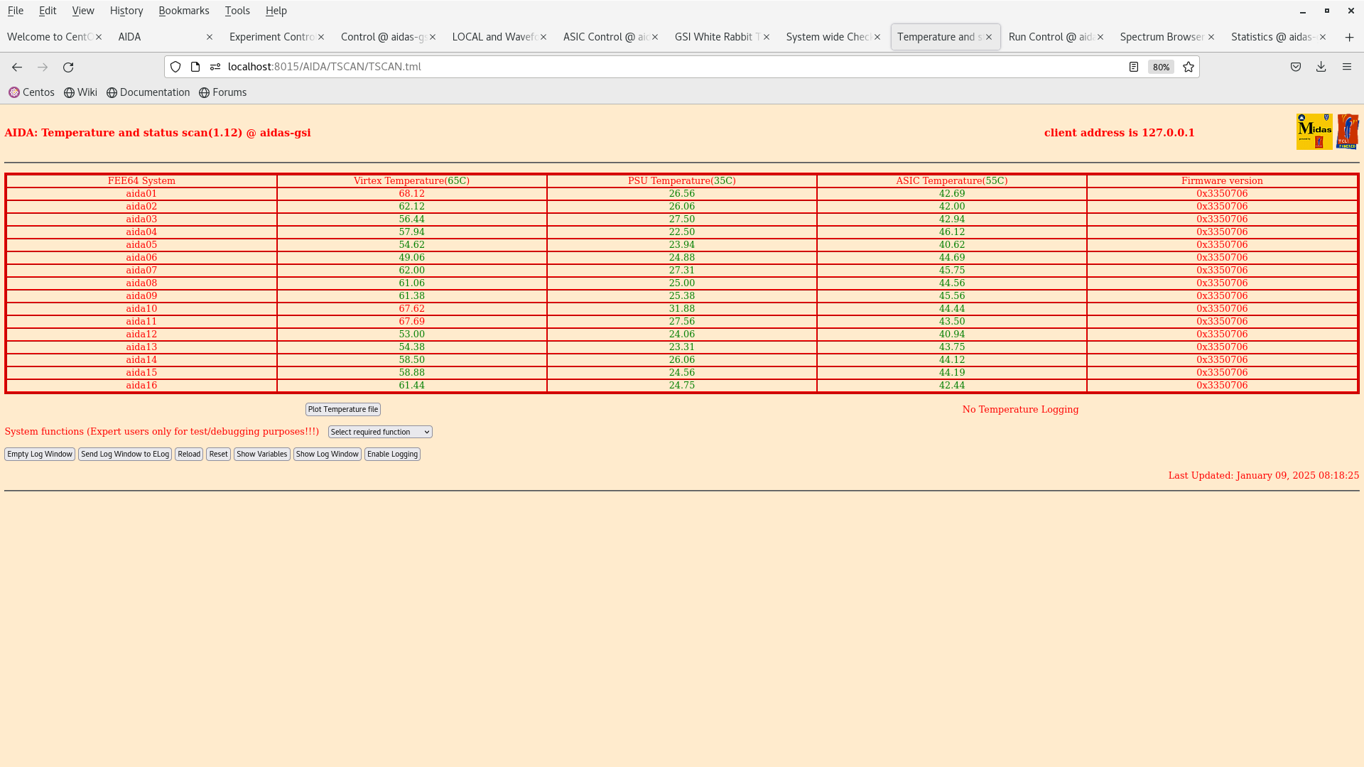
|
|
721
|
Thu Oct 23 12:22:31 2025 |
JB, GB, MP, AM, NH | 207Bi source threshold tests |
>
> We have dismounted the AIDA stack and bPlast and realigned the cables so that they can fit into the adapters.
>
> The plan for the next couple days is the following:
>
> - Alignment -- done
> - Remount cable -- done
> - Fix position w/o bPlast mounted -- done
> - Remount bracket for the last stage -- done
> - Remount AIDA 1 & 2 and the 207Bi source with the source holder -- done
> - Mount the snout and take data -- we wait till next week Monday when the heat exchanger is active again. (ongoing)
>
> The current setup at the end of work is that the snout is mount with a bPlast (uncabled) and 2 AIDA layers at the regular spaced position with a 207Bi source down stream, as can be seen in the previous elog. The source is ~1 cm away from the middle AIDA wafer.
>
> Currently what is cabled:
>
> - Signal out from the detector
> - Bias daisy chain
>
> Still to be cabled:
>
> - HV cable
> - Grounding
> - Pulser
>
> Additional info on the source position:
> - the source is at ~9.6 mm distance from the downstream detector
> - the source is placed at the centre of the middle wafer: 12.25 cm in x, 4.75 cm in y
> - the radius of the source is ~1.5 mm

The Messhuette has been cleaned and equipment has been rearranged. If there are any broken or missing components be sure to follow up with the FRS group (as I believe they have been cleaning here).

We are resuming the work on the source measurements as the cooling water is back. Some of the valves still look closed so we are investigating if the water is flowing to the setup.

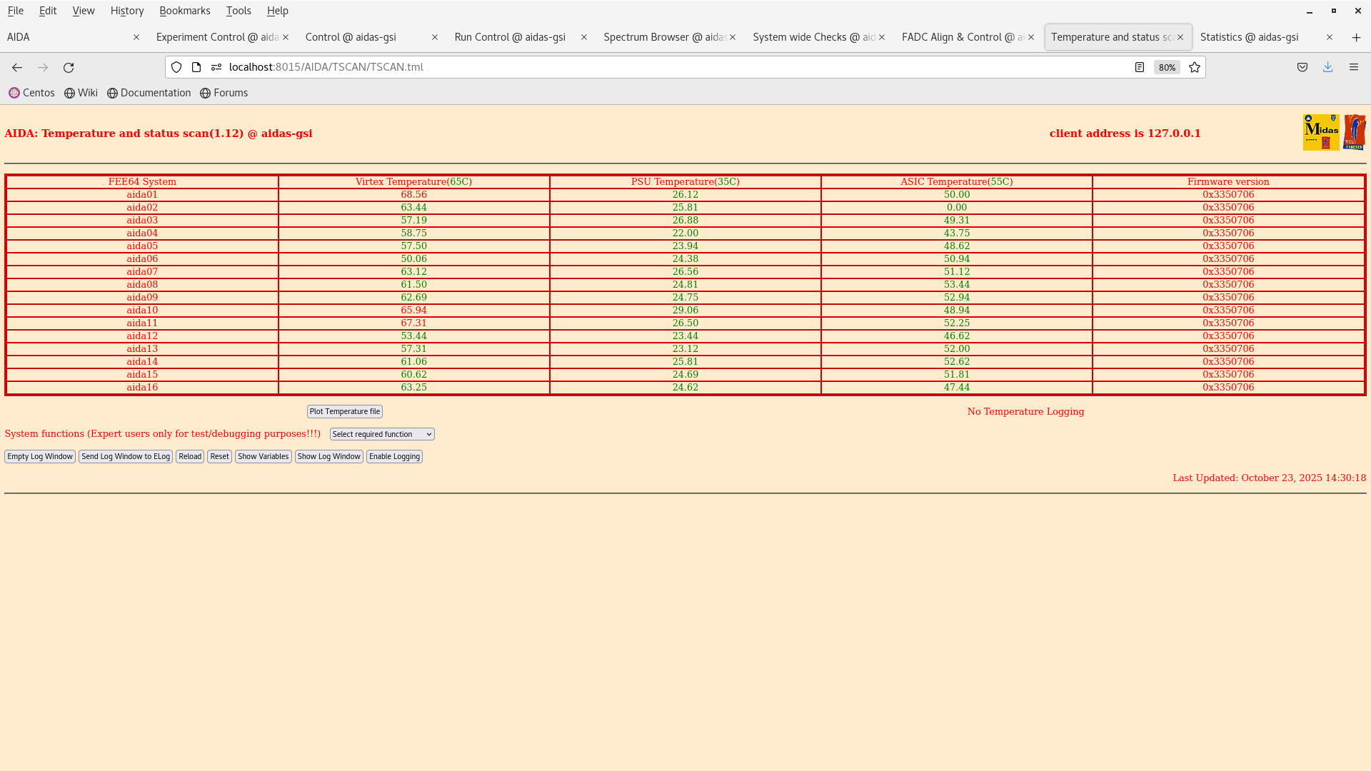
14:31 Temperature on start up OK - attachment 2.

15:41 We reset the ASIC control registers to a setup used in Feb 2024 (2025Feb24-17.14.52) to match the full AIDA setup (it was using BB7 initially in aida10).

The old bias scheme is obsolete and the bias is now done via the Ohmic side.

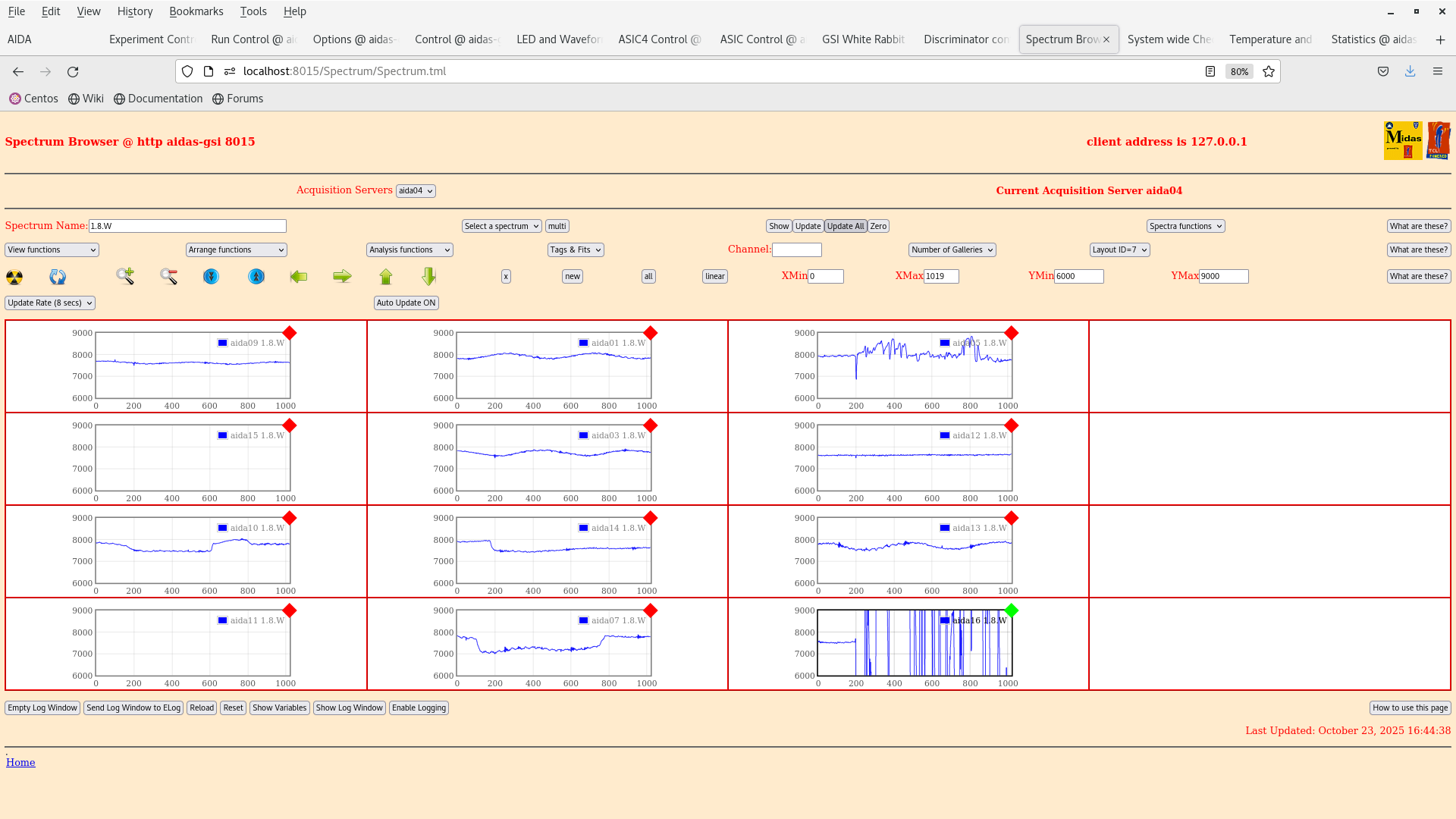
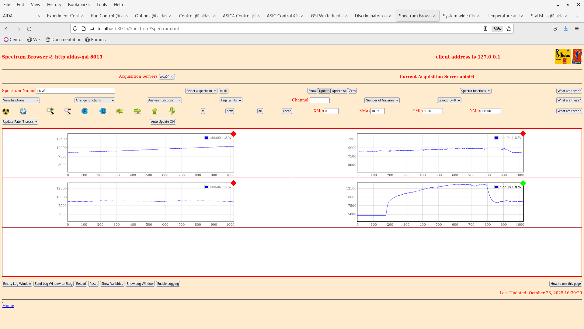
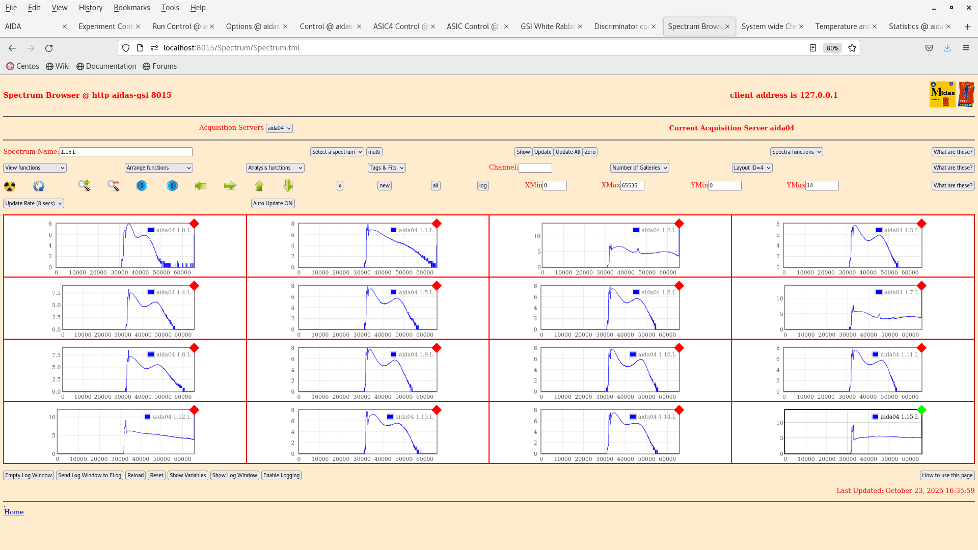
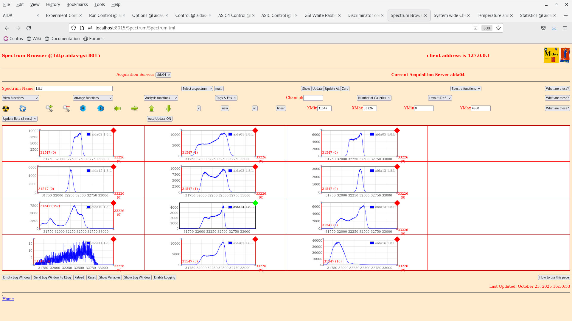
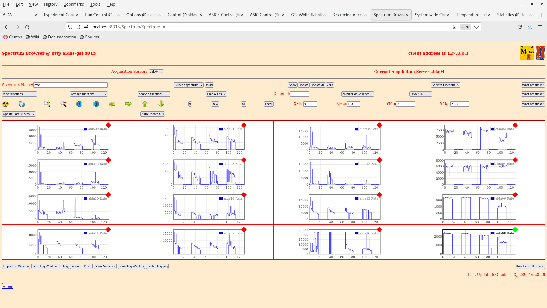
16:47 We have look at some initial spectra with the 207Bi 3-8 shows the ADC channels and waveforms of the n+n and p+n sides. Bias and grounding developed by Nabiel have been done.

We are going to wait for the system to stabilise over night so that we start taking data tomorrow. Then we can analyse the results and see what we get :) Some channels are clearly broken which can be seen in the waveforms eg. aida16. |
| Attachment 1: IMG_20251023_132958.jpg
|
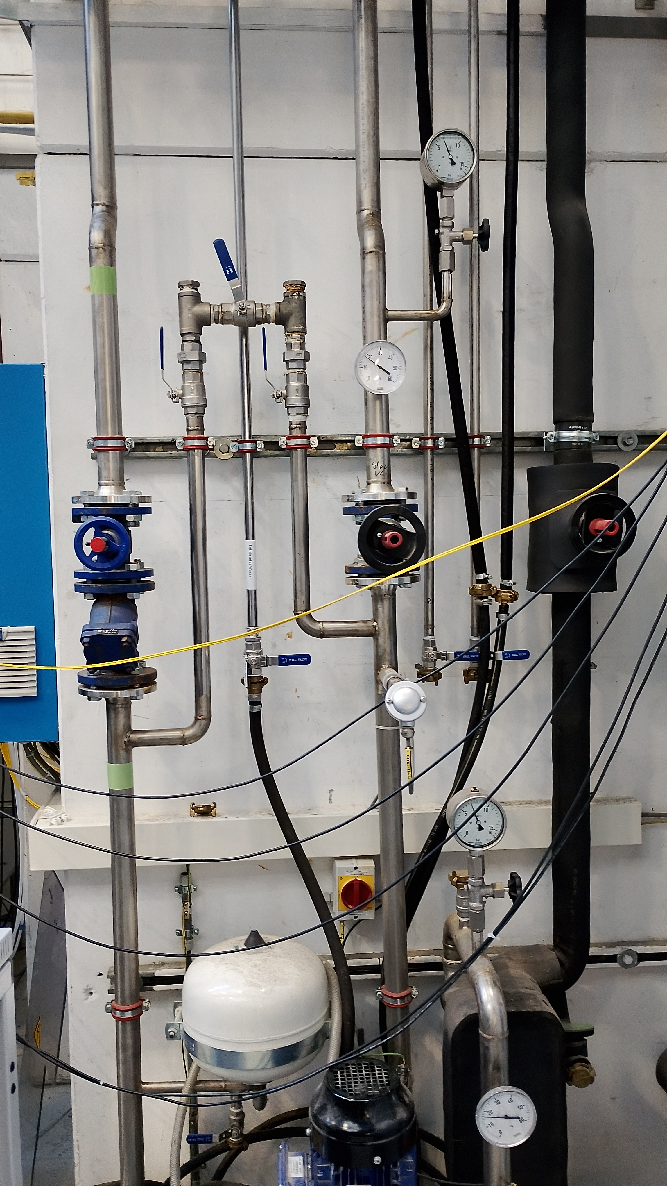
|
| Attachment 2: Screenshot_from_2025-10-23_14-30-28.png
|
|
| Attachment 3: Screenshot_from_2025-10-23_16-44-41.png
|
|
| Attachment 4: Screenshot_from_2025-10-23_16-39-32.png
|
|
| Attachment 5: Screenshot_from_2025-10-23_16-36-03.png
|
|
| Attachment 6: Screenshot_from_2025-10-23_16-31-33.png
|
|
| Attachment 7: Screenshot_from_2025-10-23_16-29-28.png
|
|
| Attachment 8: Screenshot_from_2025-10-23_16-29-15.png
|
|
|
723
|
Fri Oct 24 10:31:59 2025 |
JB, GB, MP, AM, NH | 207Bi source threshold tests |
> >
> > We have dismounted the AIDA stack and bPlast and realigned the cables so that they can fit into the adapters.
> >
> > The plan for the next couple days is the following:
> >
> > - Alignment -- done
> > - Remount cable -- done
> > - Fix position w/o bPlast mounted -- done
> > - Remount bracket for the last stage -- done
> > - Remount AIDA 1 & 2 and the 207Bi source with the source holder -- done
> > - Mount the snout and take data -- we wait till next week Monday when the heat exchanger is active again. (ongoing)
> >
> > The current setup at the end of work is that the snout is mount with a bPlast (uncabled) and 2 AIDA layers at the regular spaced position with a 207Bi source down stream, as can be seen in the previous elog. The source is ~1 cm away from the middle AIDA wafer.
> >
> > Currently what is cabled:
> >
> > - Signal out from the detector
> > - Bias daisy chain
> >
> > Still to be cabled:
> >
> > - HV cable
> > - Grounding
> > - Pulser
> >
> > Additional info on the source position:
> > - the source is at ~9.6 mm distance from the downstream detector
> > - the source is placed at the centre of the middle wafer: 12.25 cm in x, 4.75 cm in y
> > - the radius of the source is ~1.5 mm
>
> The Messhuette has been cleaned and equipment has been rearranged. If there are any broken or missing components be sure to follow up with the FRS group (as I believe they have been cleaning here).
>
> We are resuming the work on the source measurements as the cooling water is back. Some of the valves still look closed so we are investigating if the water is flowing to the setup.
>
> 14:31 Temperature on start up OK - attachment 2.
>
> 15:41 We reset the ASIC control registers to a setup used in Feb 2024 (2025Feb24-17.14.52) to match the full AIDA setup (it was using BB7 initially in aida10).
>
> The old bias scheme is obsolete and the bias is now done via the Ohmic side.
>
> 16:47 We have look at some initial spectra with the 207Bi 3-8 shows the ADC channels and waveforms of the n+n and p+n sides. Bias and grounding developed by Nabiel have been done.
>
> We are going to wait for the system to stabilise over night so that we start taking data tomorrow. Then we can analyse the results and see what we get :) Some channels are clearly broken which can be seen in the waveforms eg. aida16.

11:31 The detector was turned off last night to put it into a safe state. We return to make some comparison of the noise w.r.t the tests performed by Nabil and co.

email snippet:

"
I would suggest that you first quantify current noise performance (slow comparators -> 0x64 to reduce rate, measure pulser peak width) for each FEE64 (use layouts 3 and 4) and compare to Nabil's most recent test results. Looking at last night's 1.8.W spectra I would assume that they would be significantly worse but best to check.

I would then suggest you carefully check

    Grounding configuration (both internal and external to the snout) used Nabil's most recent tests has actually been re-established
    Grounding of the bPlas cabling
"

We are going to restart the DAQ and set the LEC thresholds to 0x64 and compare the peak FWHM with a pulser.

11:50 We started up the DAQ temps and bias look OK.

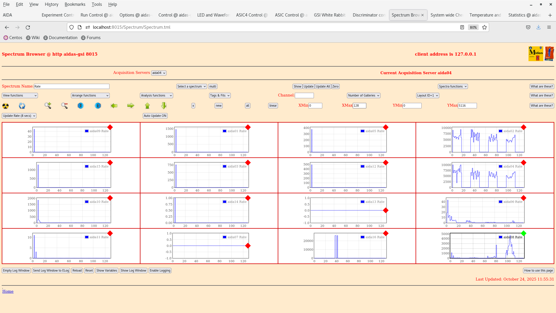
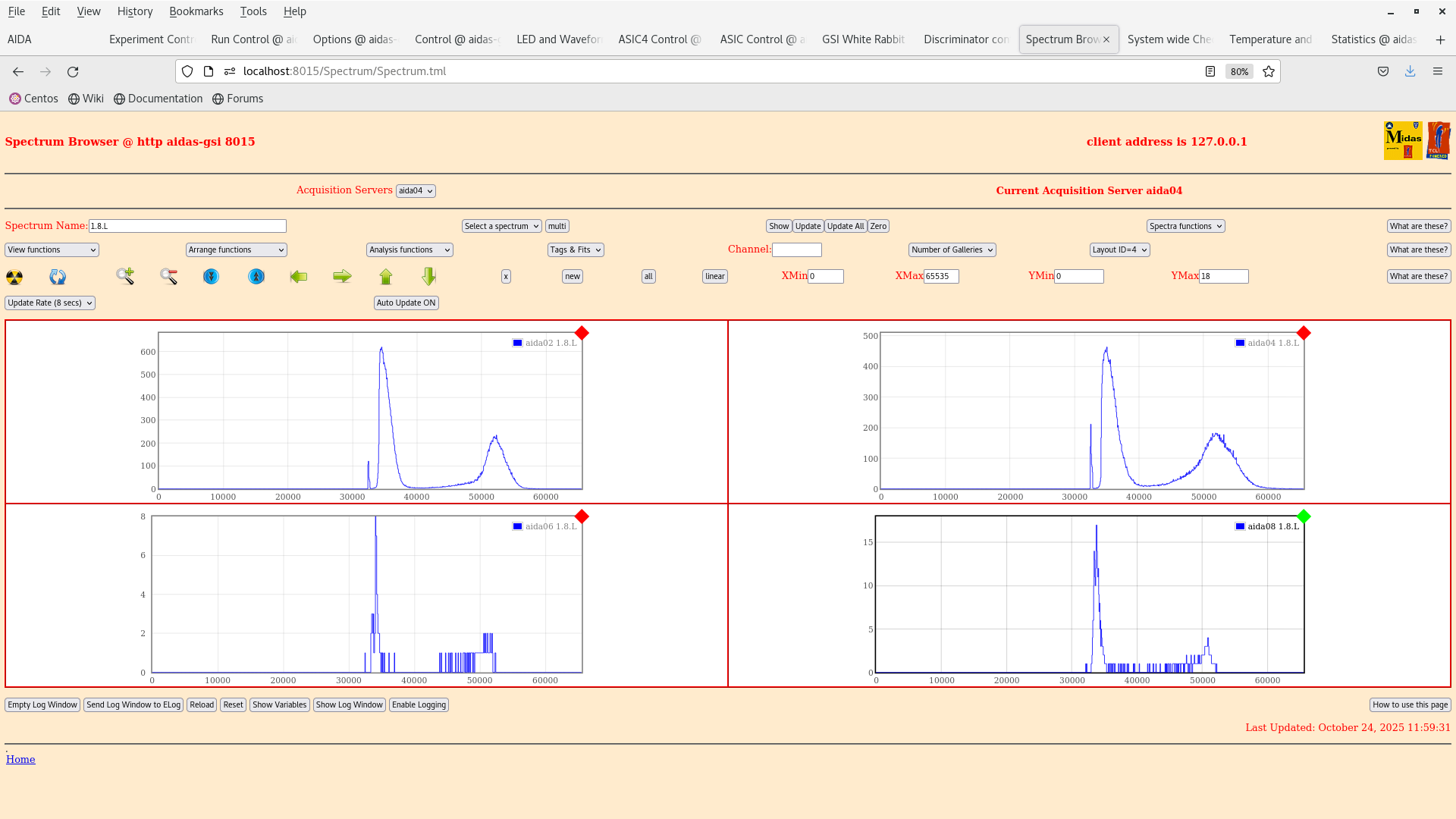
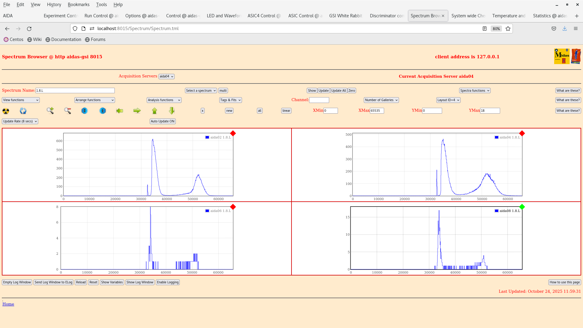
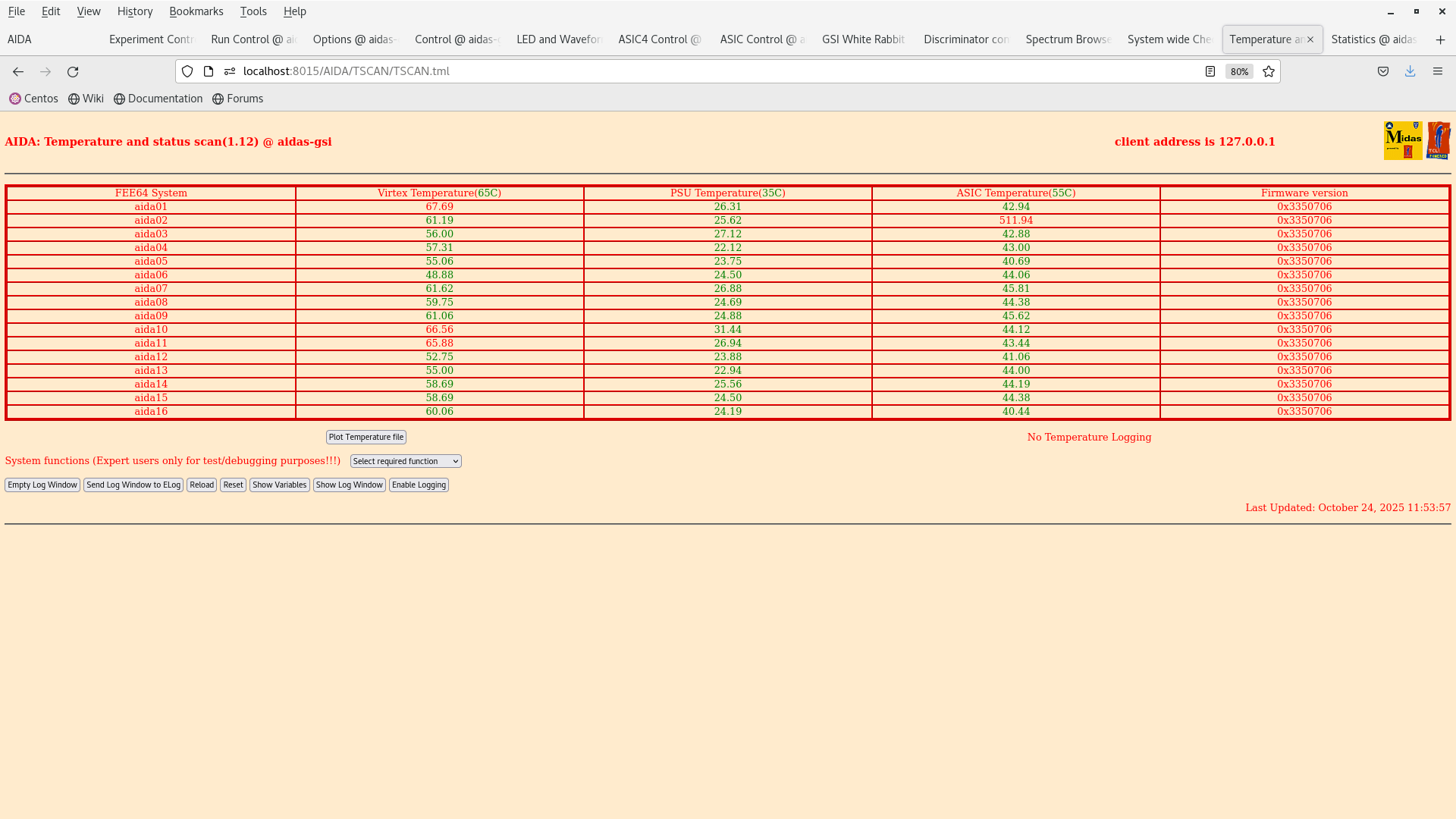
12:00 We set the thresholds on each ASIC in the slow comparator LEC to 0x64. This should correspond to a high threshold. For some reason the y-strips are still noisy (wrong polarity in the register ?) |
| Attachment 1: Screenshot_from_2025-10-24_11-56-06.png
|
|
| Attachment 2: Screenshot_from_2025-10-24_12-00-30.png
|
|
| Attachment 3: Screenshot_from_2025-10-24_11-59-35.png
|
|
| Attachment 4: Screenshot_from_2025-10-24_11-55-02.png
|
|
| Attachment 5: Screenshot_from_2025-10-24_11-54-09.png
|
|
| Attachment 6: Screenshot_from_2025-10-24_11-53-59.png
|
|
|
724
|
Fri Oct 24 12:29:02 2025 |
JB, GB, MP, AM, NH | 207Bi source threshold tests |
> > >
> > > We have dismounted the AIDA stack and bPlast and realigned the cables so that they can fit into the adapters.
> > >
> > > The plan for the next couple days is the following:
> > >
> > > - Alignment -- done
> > > - Remount cable -- done
> > > - Fix position w/o bPlast mounted -- done
> > > - Remount bracket for the last stage -- done
> > > - Remount AIDA 1 & 2 and the 207Bi source with the source holder -- done
> > > - Mount the snout and take data -- we wait till next week Monday when the heat exchanger is active again. (ongoing)
> > >
> > > The current setup at the end of work is that the snout is mount with a bPlast (uncabled) and 2 AIDA layers at the regular spaced position with a 207Bi source down stream, as can be seen in the previous elog. The source is ~1 cm away from the middle AIDA wafer.
> > >
> > > Currently what is cabled:
> > >
> > > - Signal out from the detector
> > > - Bias daisy chain
> > >
> > > Still to be cabled:
> > >
> > > - HV cable
> > > - Grounding
> > > - Pulser
> > >
> > > Additional info on the source position:
> > > - the source is at ~9.6 mm distance from the downstream detector
> > > - the source is placed at the centre of the middle wafer: 12.25 cm in x, 4.75 cm in y
> > > - the radius of the source is ~1.5 mm
> >
> > The Messhuette has been cleaned and equipment has been rearranged. If there are any broken or missing components be sure to follow up with the FRS group (as I believe they have been cleaning here).
> >
> > We are resuming the work on the source measurements as the cooling water is back. Some of the valves still look closed so we are investigating if the water is flowing to the setup.
> >
> > 14:31 Temperature on start up OK - attachment 2.
> >
> > 15:41 We reset the ASIC control registers to a setup used in Feb 2024 (2025Feb24-17.14.52) to match the full AIDA setup (it was using BB7 initially in aida10).
> >
> > The old bias scheme is obsolete and the bias is now done via the Ohmic side.
> >
> > 16:47 We have look at some initial spectra with the 207Bi 3-8 shows the ADC channels and waveforms of the n+n and p+n sides. Bias and grounding developed by Nabiel have been done.
> >
> > We are going to wait for the system to stabilise over night so that we start taking data tomorrow. Then we can analyse the results and see what we get :) Some channels are clearly broken which can be seen in the waveforms eg. aida16.
>
> 11:31 The detector was turned off last night to put it into a safe state. We return to make some comparison of the noise w.r.t the tests performed by Nabil and co.
>
> email snippet:
>
> "
> I would suggest that you first quantify current noise performance (slow comparators -> 0x64 to reduce rate, measure pulser peak width) for each FEE64 (use layouts 3 and 4) and compare to Nabil's most recent test results. Looking at last night's 1.8.W spectra I would assume that they would be significantly worse but best to check.
>
> I would then suggest you carefully check
>
>     Grounding configuration (both internal and external to the snout) used Nabil's most recent tests has actually been re-established
>     Grounding of the bPlas cabling
> "
>
> We are going to restart the DAQ and set the LEC thresholds to 0x64 and compare the peak FWHM with a pulser.
>
> 11:50 We started up the DAQ temps and bias look OK.
>
> 12:00 We set the thresholds on each ASIC in the slow comparator LEC to 0x64. This should correspond to a high threshold. For some reason the y-strips are still noisy (wrong polarity in the register ?)

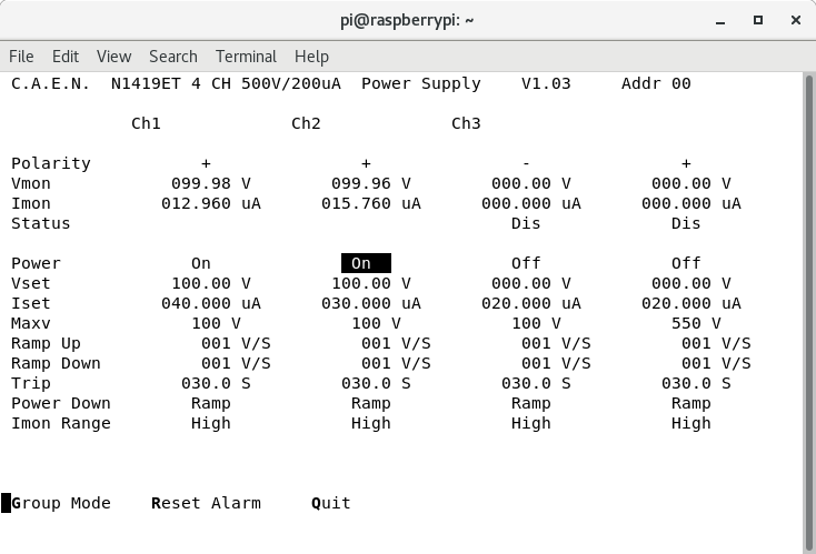
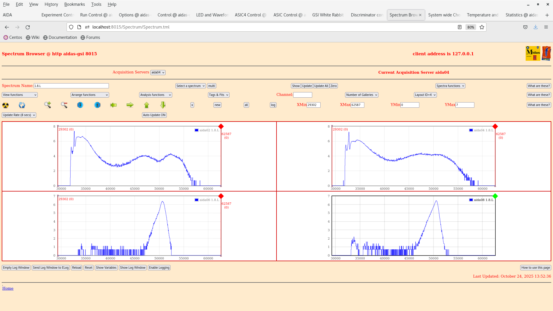
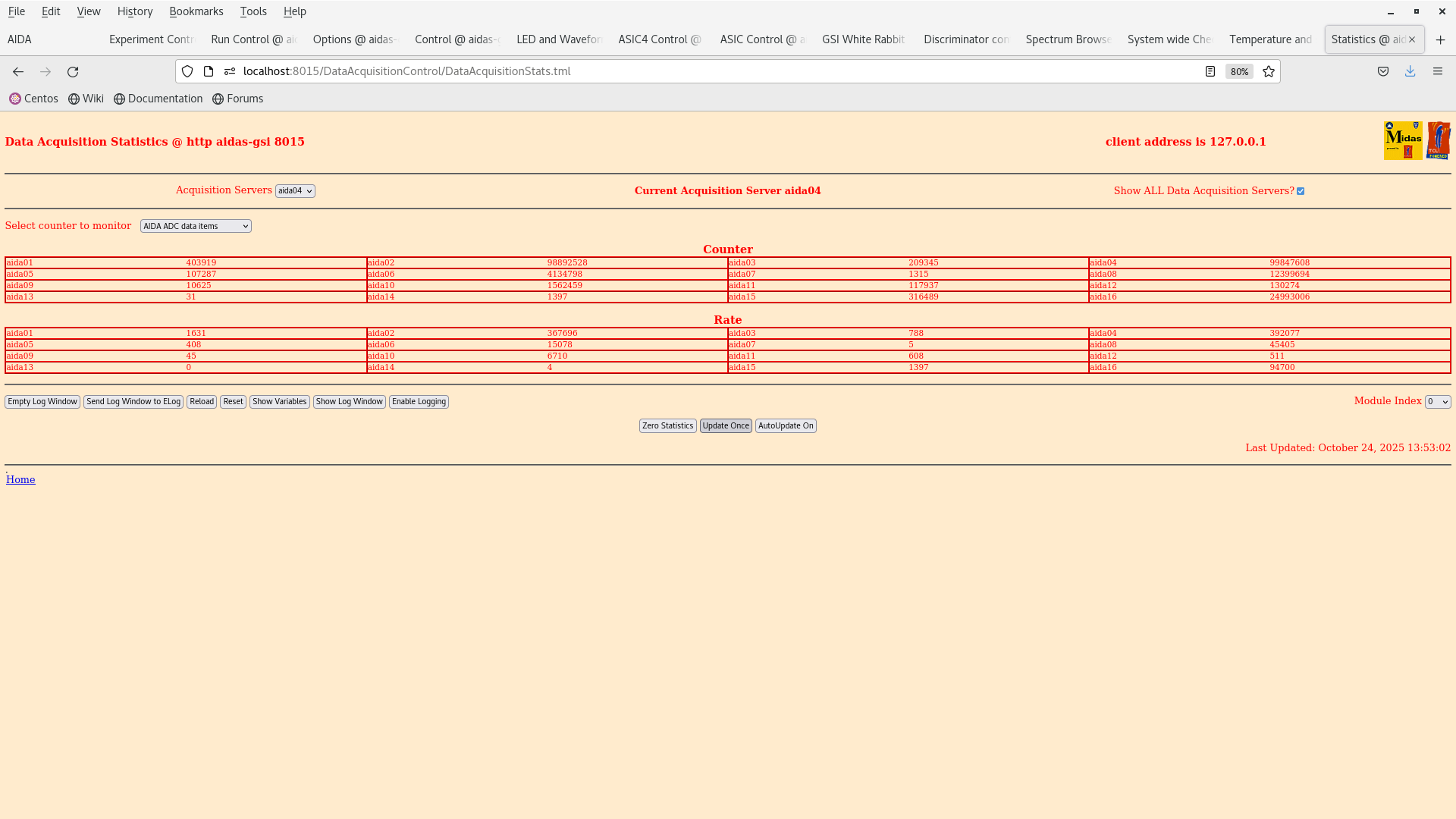
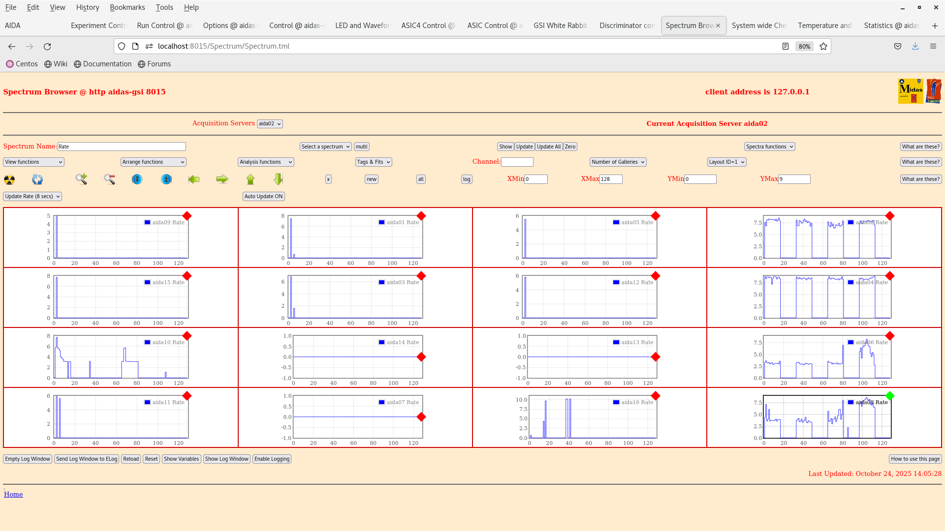
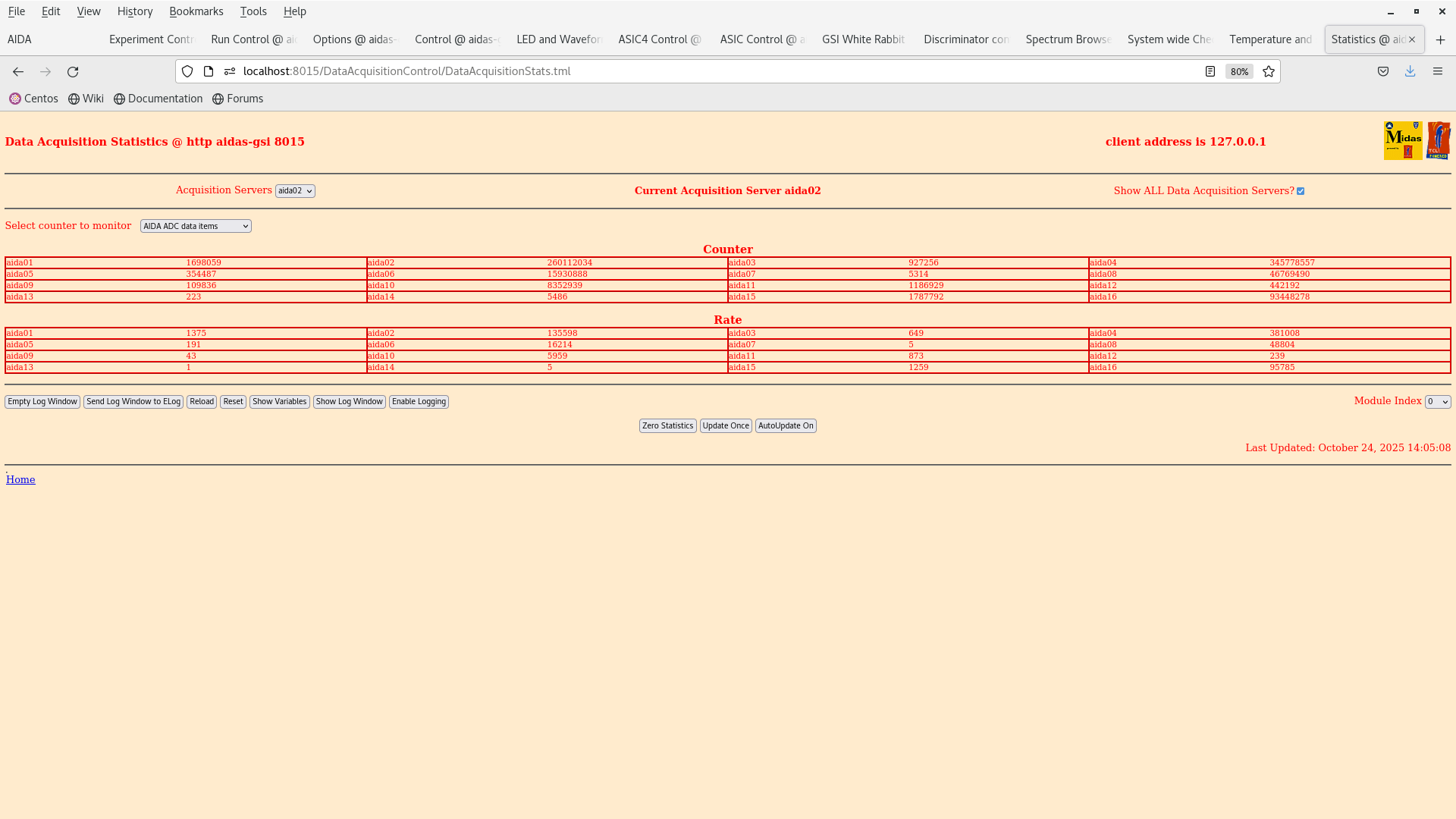
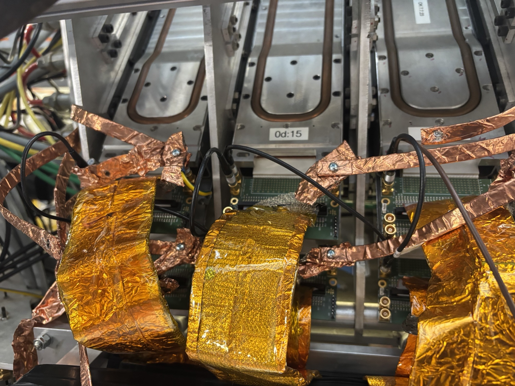
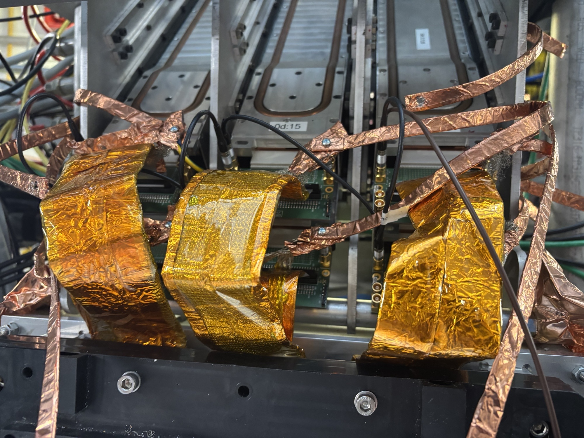
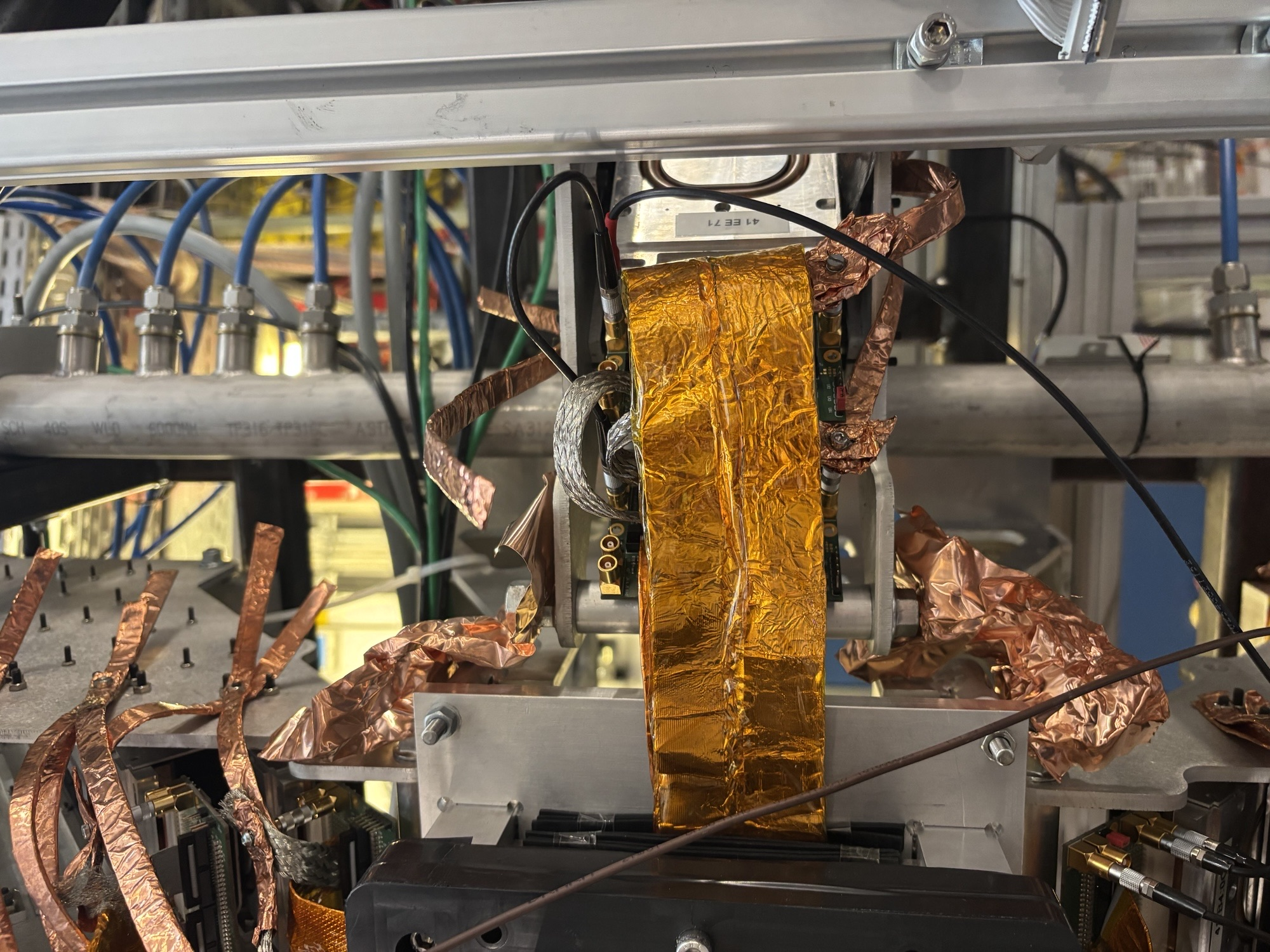
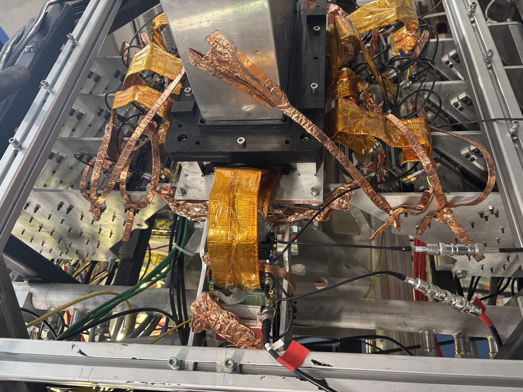
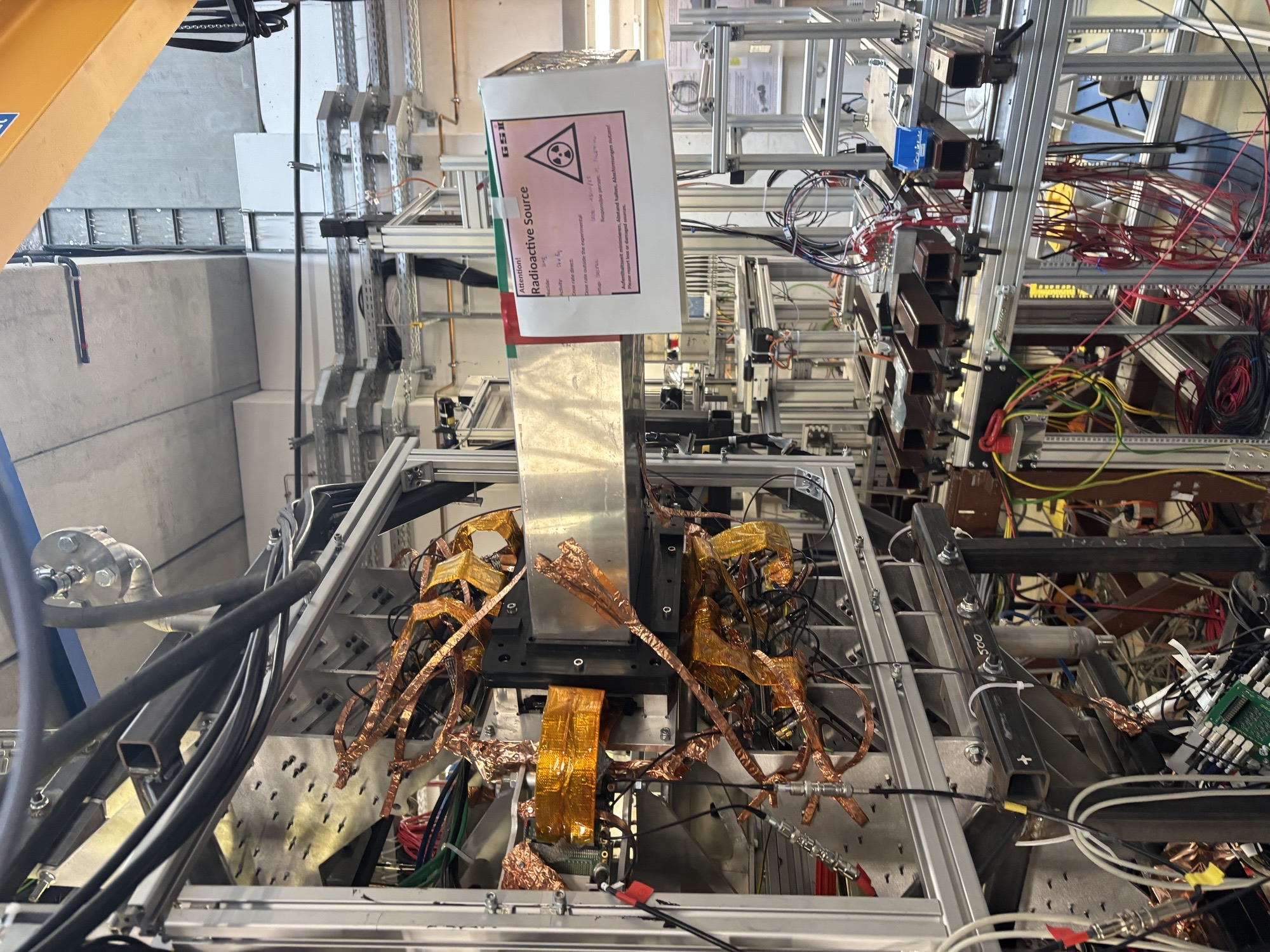
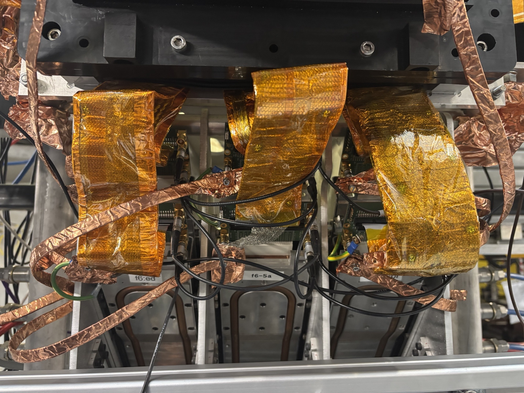
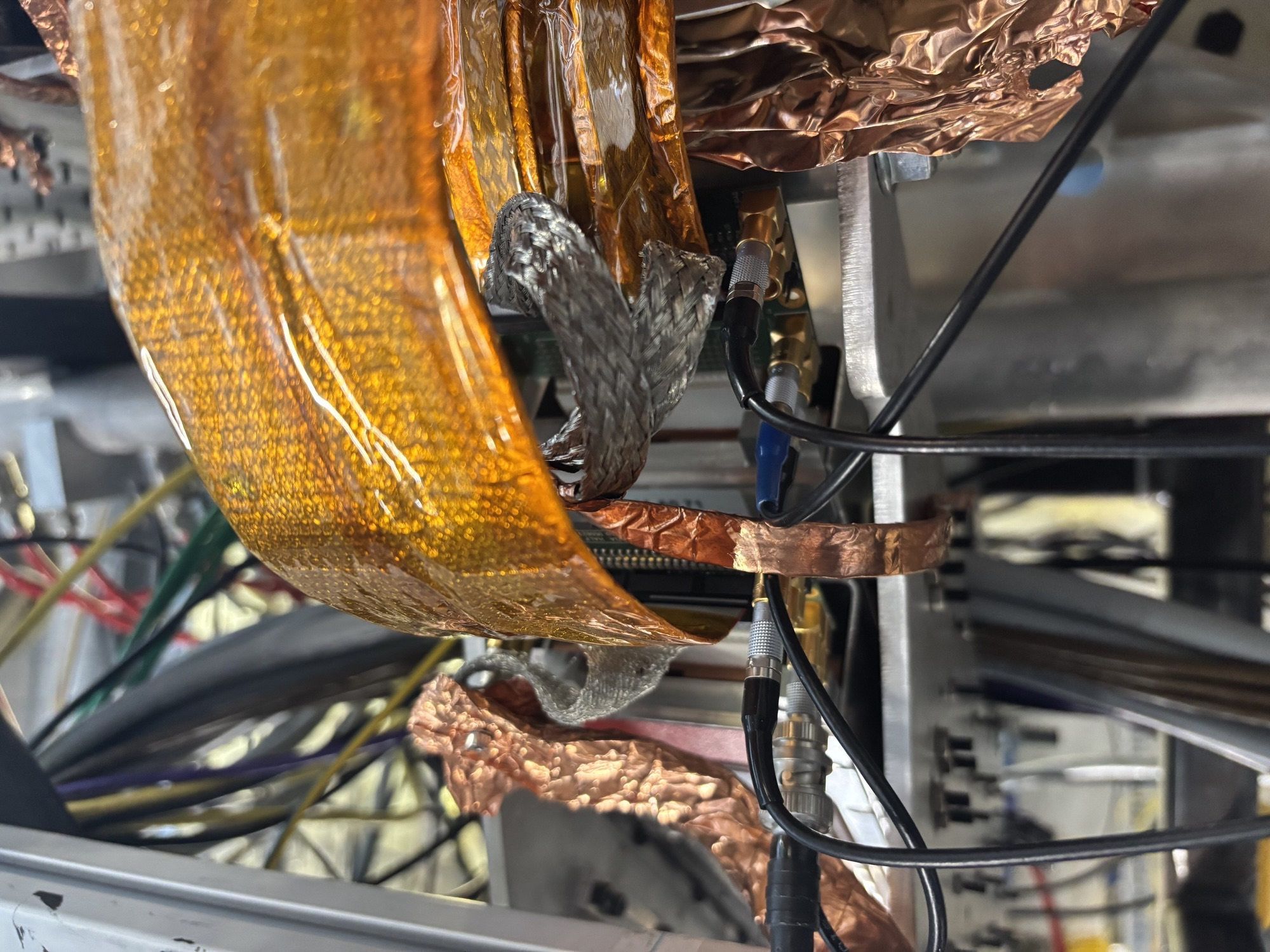
13:28 we returned after a hearty lunch. When turning on the FEE64s we noticed that the bias of the CAEN to the detector increases by 0.3 V.

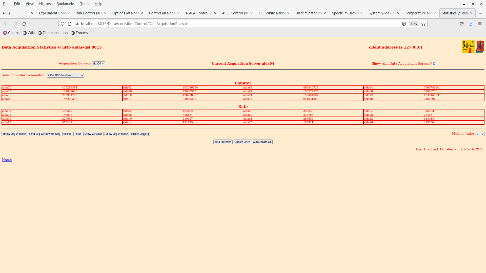
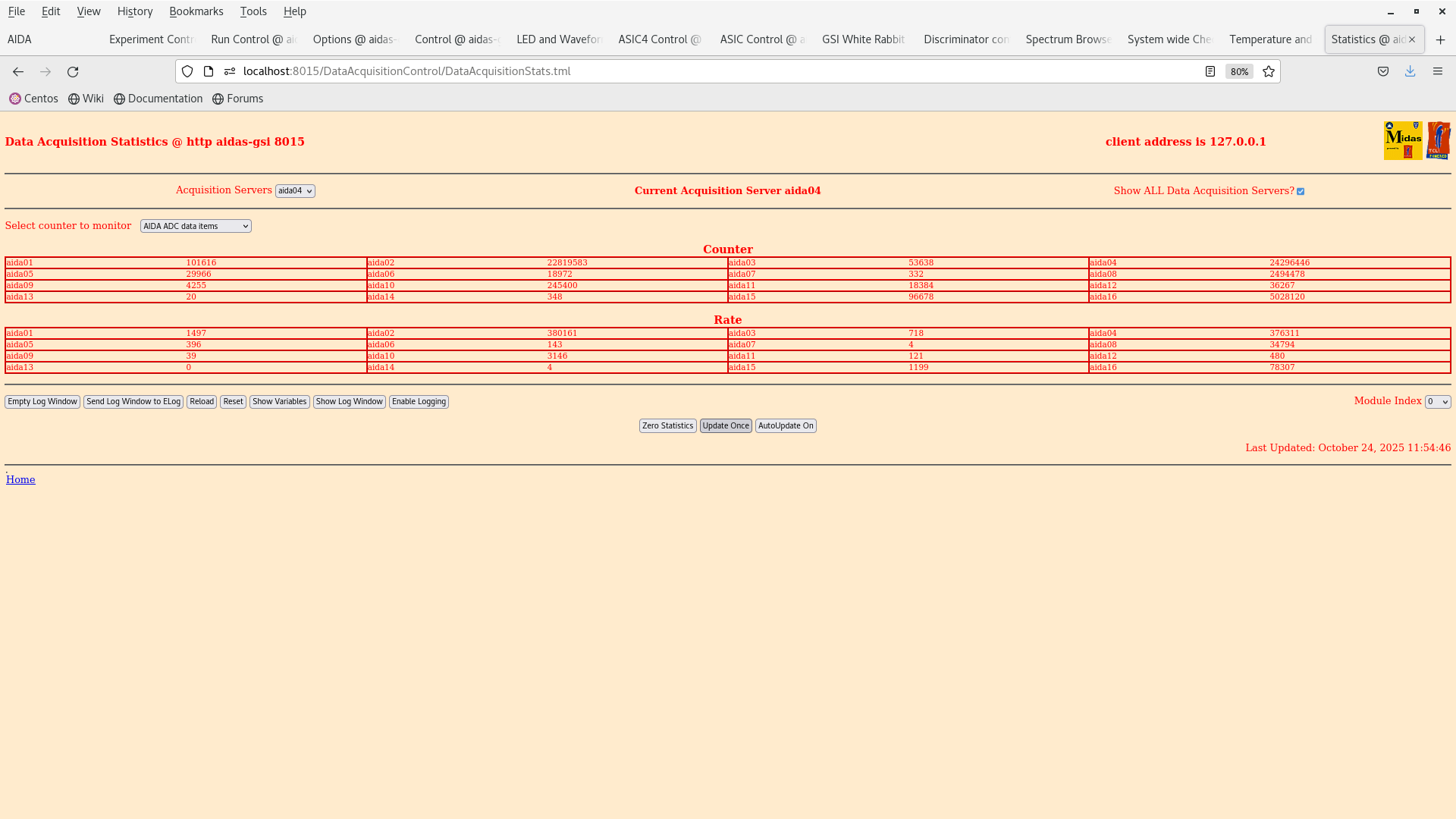
We rebiased and set the thresholds in one FEE64 aida02 to 0xff (very high, attachment 2) and the detector is still reading about 100 kHz ADC items. When the threshold was set to 0x64 it was 360 kHz (attachment 4).

We bias down the system to cross-check the cabling etc. |
| Attachment 1: Screenshot_from_2025-10-24_13-52-42.png
|
|
| Attachment 2: Screenshot_from_2025-10-24_13-53-05.png
|
|
| Attachment 3: Screenshot_from_2025-10-24_14-08-56.png
|
|
| Attachment 4: Screenshot_from_2025-10-24_14-08-52.png
|
|
| Attachment 5: IMG_5919.jpeg
|
|
| Attachment 6: IMG_5918.jpeg
|
|
| Attachment 7: IMG_5917.jpeg
|
|
| Attachment 8: IMG_5914.jpeg
|
|
| Attachment 9: IMG_5913.jpeg
|
|
| Attachment 10: IMG_5915.jpeg
|
|
| Attachment 11: IMG_5916.jpeg
|
|
|
725
|
Fri Oct 24 14:33:37 2025 |
JB, GB, MP, AM | Snout grounding, bias and test input layout as of 24.10.2025 |
|
| Attachment 1: AIDA_scheme_241020525(2).pdf
|
-0.png)
|
|
729
|
Tue Oct 28 12:43:38 2025 |
JB, GB, MP, AM | Further setup of tests for 207Bi test |
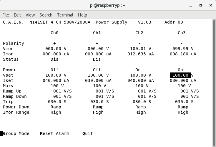
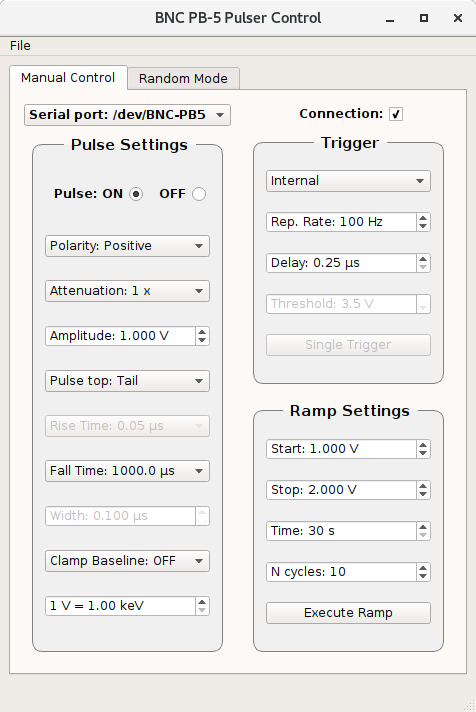
- Ch 2 and 3 of CAEN HV module changed to negative polarity, Ch 0,1 still with positive polarity
- Bias changed from the n+n to the p+n side (now Ch 2,3) - att. 1

- EXPERIMENTS/AIDA/2025Oct28-14.55.15 -> Slow comparitor -> 0x64 (1MeV) p+n Pos. bias & n+n Neg. bias

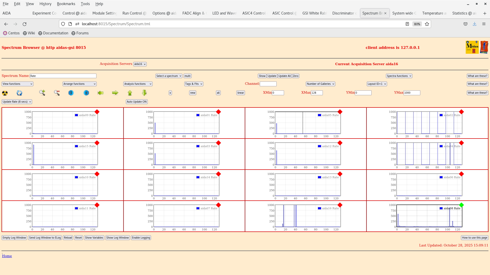
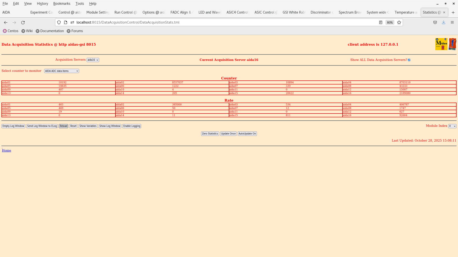
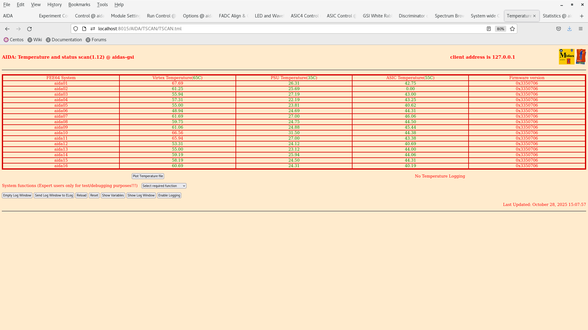
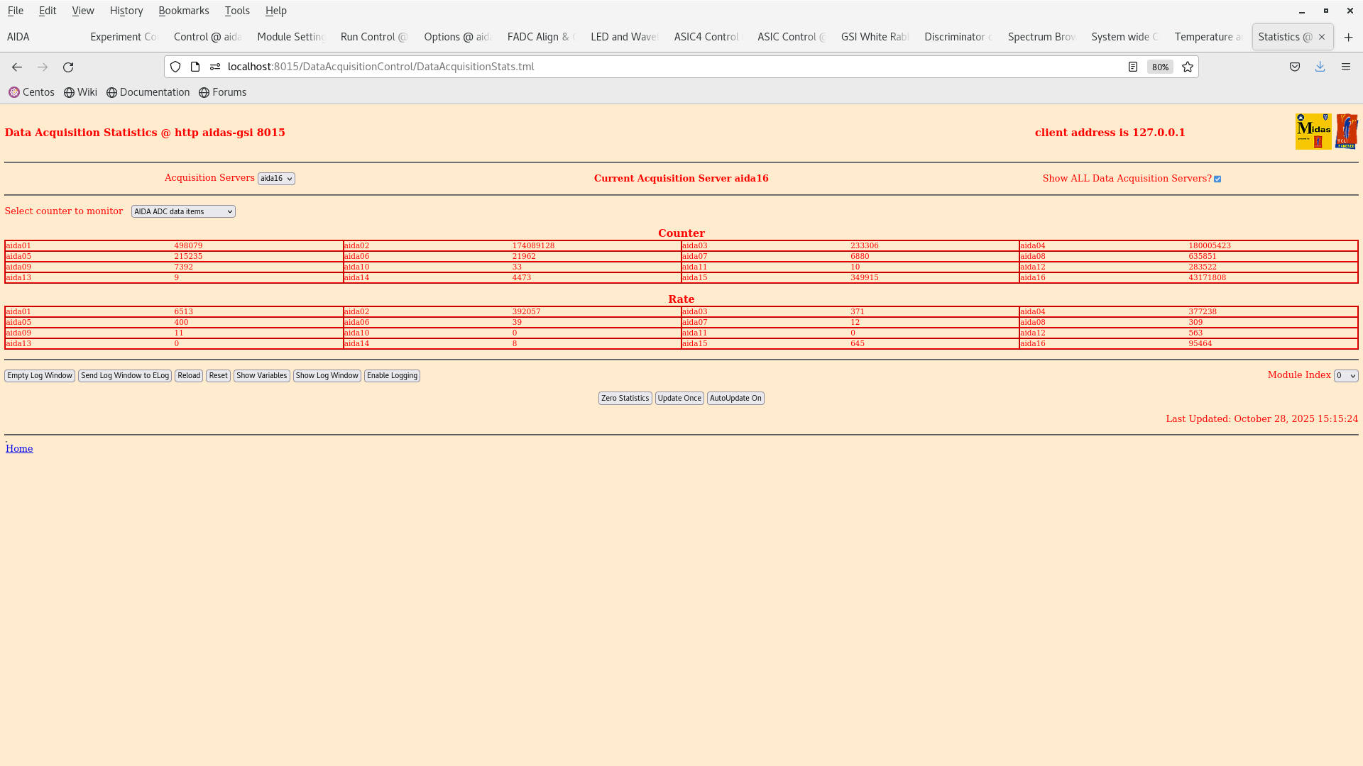
- Attachment 7: aida01 had its threshold lowered to 500 keV -> Rate increased from 500 to 6500 Hz
- Pulser inputs plugged in.


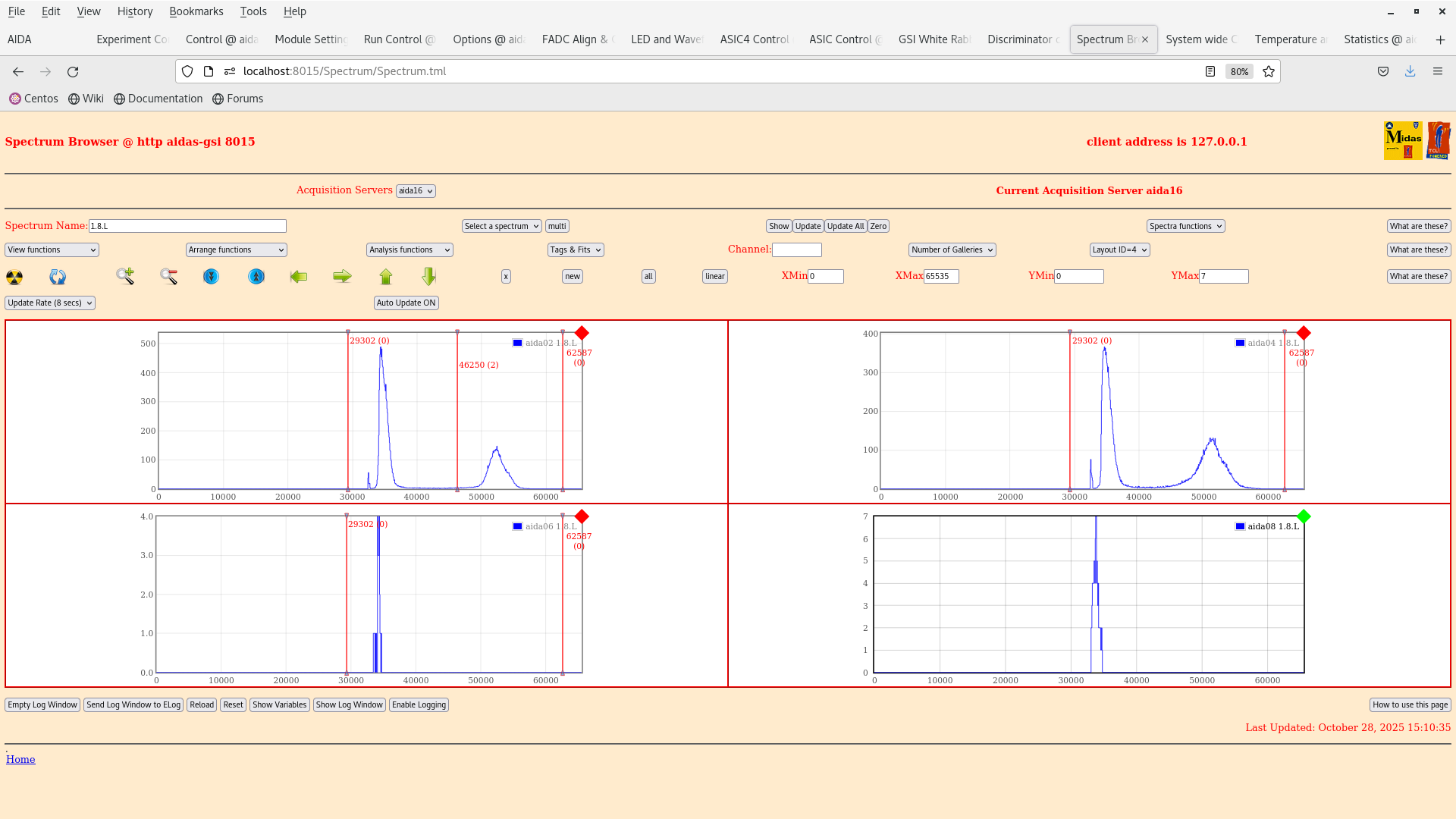
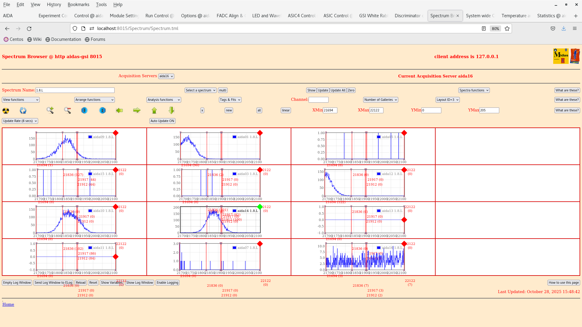
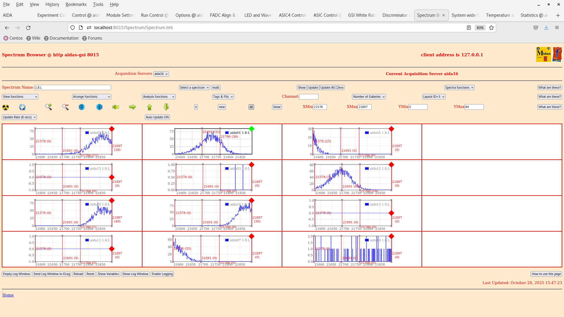
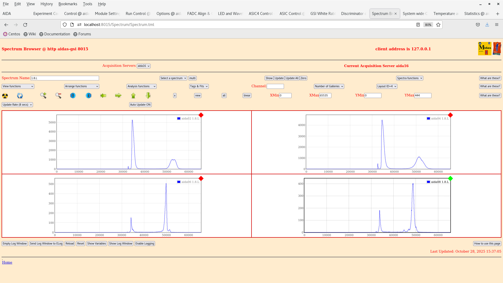
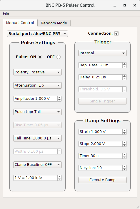
We have input a 1V pulser input into the data and have measured a peak in aida01 with a FWHM = 75 channel see attachment 9 and a FWHM in aida 14 (DSSD2) of also 76 channels which is similar to the results obtained in June from Nabil.


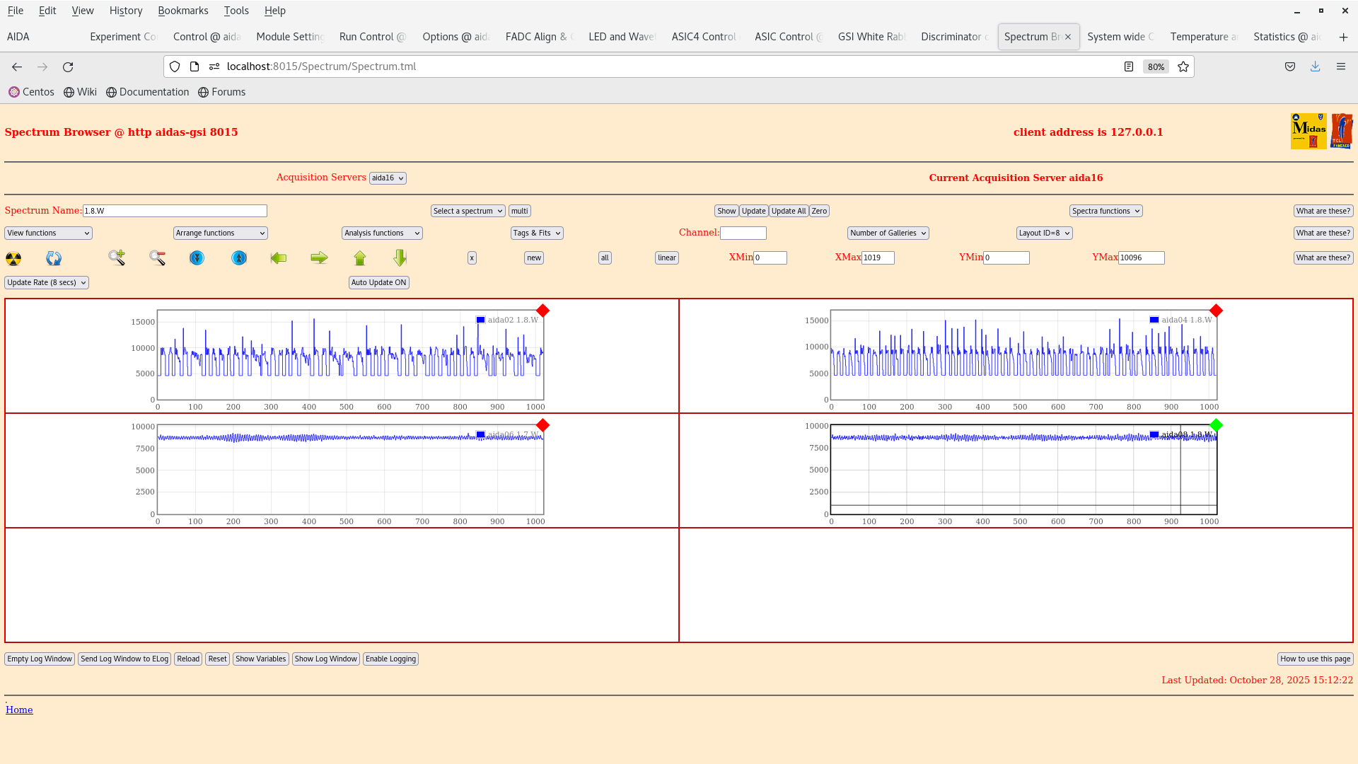
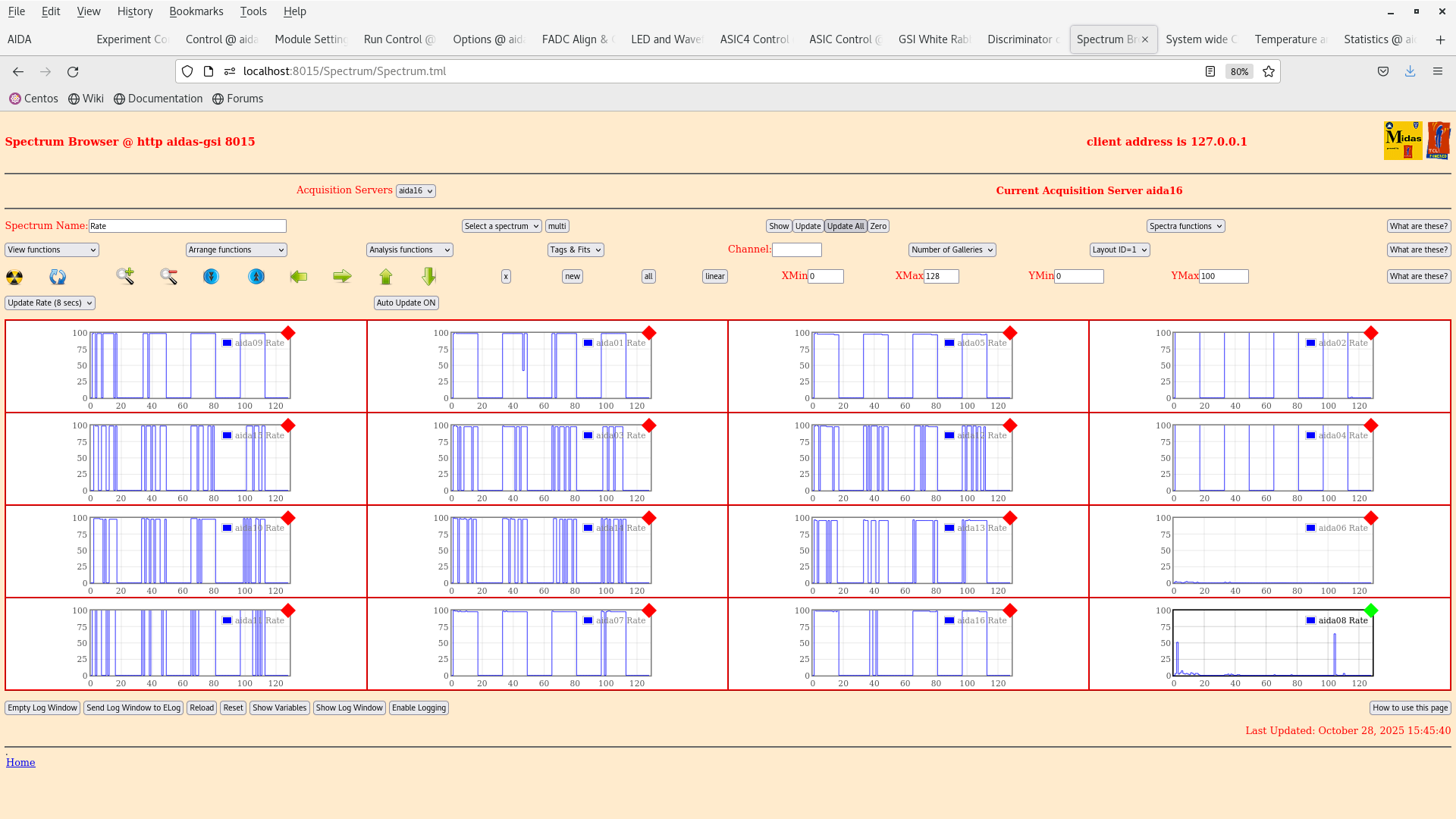
We cannot see anything from the n+n side as the signals are too noisy. Probably best to go with a higher trigger rate on the pulser and check with log scale tomorrow. It might also be worth checking the grounding on the y-strips as the problem with biasing with positive polarity is still seen in aida02 and aida04 (high noise repetition0 signal, attachment 2).

Conclusion is that we have reproduced in part the result from Nabil.

Tomorrow we will continue with the tests by lowering the thresholds and hopefully collect some data :-) |
| Attachment 1: Screenshot_from_2025-10-28_14-28-30.png
|
|
| Attachment 2: Screenshot_from_2025-10-28_15-12-27.png
|
|
| Attachment 3: Screenshot_from_2025-10-28_15-10-42.png
|
|
| Attachment 4: Screenshot_from_2025-10-28_15-09-59.png
|
|
| Attachment 5: Screenshot_from_2025-10-28_15-08-24.png
|
|
| Attachment 6: Screenshot_from_2025-10-28_15-08-02.png
|
|
| Attachment 7: Screenshot_from_2025-10-28_15-15-31.png
|
|
| Attachment 8: Screenshot_from_2025-10-28_15-49-20.png
|
|
| Attachment 9: Screenshot_from_2025-10-28_15-47-44.png
|
|
| Attachment 10: Screenshot_from_2025-10-28_15-45-44.png
|
|
| Attachment 11: Screenshot_from_2025-10-28_15-37-13.png
|
|
| Attachment 12: Screenshot_from_2025-10-28_15-31-20.png
|
|
| Attachment 13: Screenshot_from_2025-10-28_15-50-19.png
|
|
| Attachment 14: AIDA_scheme_241020525(1).png
|
.png.png)
|
|
720
|
Wed Oct 15 09:41:24 2025 |
JB, GB, MP | 207Bi source threshold tests |
We have dismounted the AIDA stack and bPlast and realigned the cables so that they can fit into the adapters.

The plan for the next couple days is the following:

- Alignment -- done
- Remount cable -- done
- Fix position w/o bPlast mounted -- done
- Remount bracket for the last stage -- done
- Remount AIDA 1 & 2 and the 207Bi source with the source holder -- done
- Mount the snout and take data -- we wait till next week Monday when the heat exchanger is active again. (ongoing)

The current setup at the end of work is that the snout is mount with a bPlast (uncabled) and 2 AIDA layers at the regular spaced position with a 207Bi source down stream, as can be seen in the previous elog. The source is ~1 cm away from the middle AIDA wafer.

Currently what is cabled:

- Signal out from the detector
- Bias daisy chain

Still to be cabled:

- HV cable
- Grounding
- Pulser

Additional info on the source position:
- the source is at ~9.6 mm distance from the downstream detector
- the source is placed at the centre of the middle wafer: 12.25 cm in x, 4.75 cm in y
- the radius of the source is ~1.5 mm |
| Attachment 1: IMG_5796.jpg
|

|
| Attachment 2: IMG_5797.jpg
|

|
| Attachment 3: IMG_5798.jpg
|

|
|
743
|
Fri Nov 7 12:30:30 2025 |
JB, GB, MP | Pulser walkthrough for source tests. |
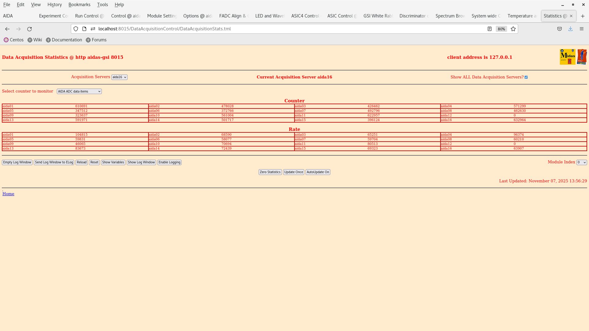
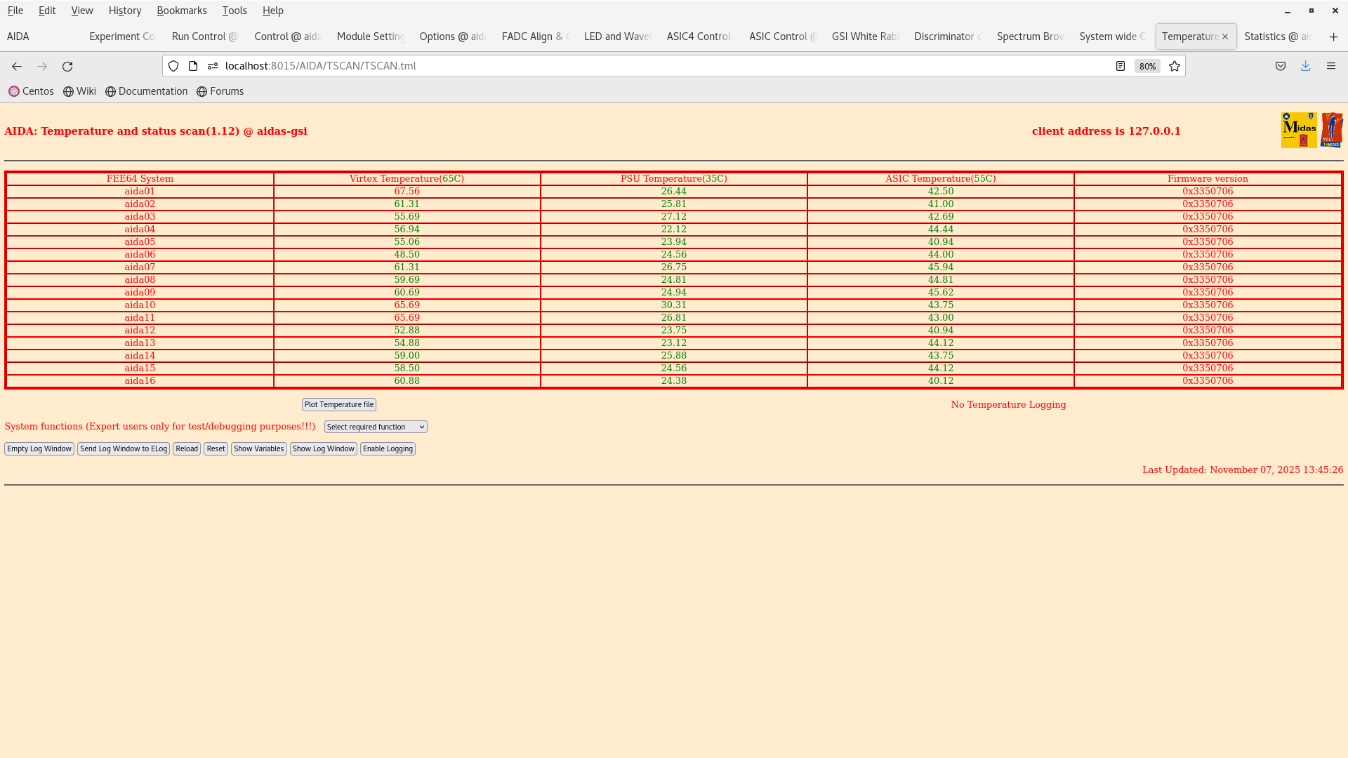
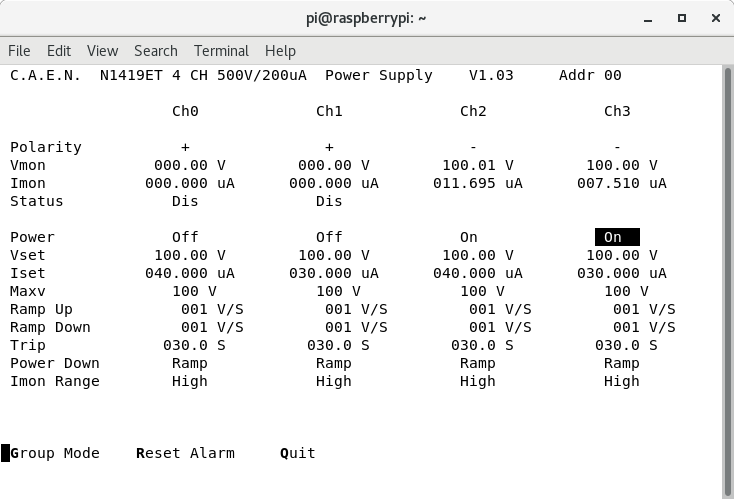
13:30 We are going to do the pulser walkthrough for the the source tests.

We are wrapping the snout in some copper first to further establish a better connection with the ground.

2025Nov07-13.55.01 is a setting with 100 keV threshold across all FEEs.

We got the DAQ running, TEMPS ok and biased OK. We execute the pulser walkthrough as follow:

10x attenuation - 10V -> 1V in steps of 1 V

/lustre/despec/aida_sourcetest_2025/raw/

pulser_wt_10V - 10V

pulser_wt_9V - 9V

pulser_wt_8V - 8V

pulser_wt_7V - 7V

pulser wt_6V - 6V

pulser_wt_5V - 5V

pulser_wt_4V - 4V

pulser_wt_3V - 3V

pulser_wt_2V - 2V

pulser_wt_1V - 1V

Data taking stopped and we turn off the system to a safe state.

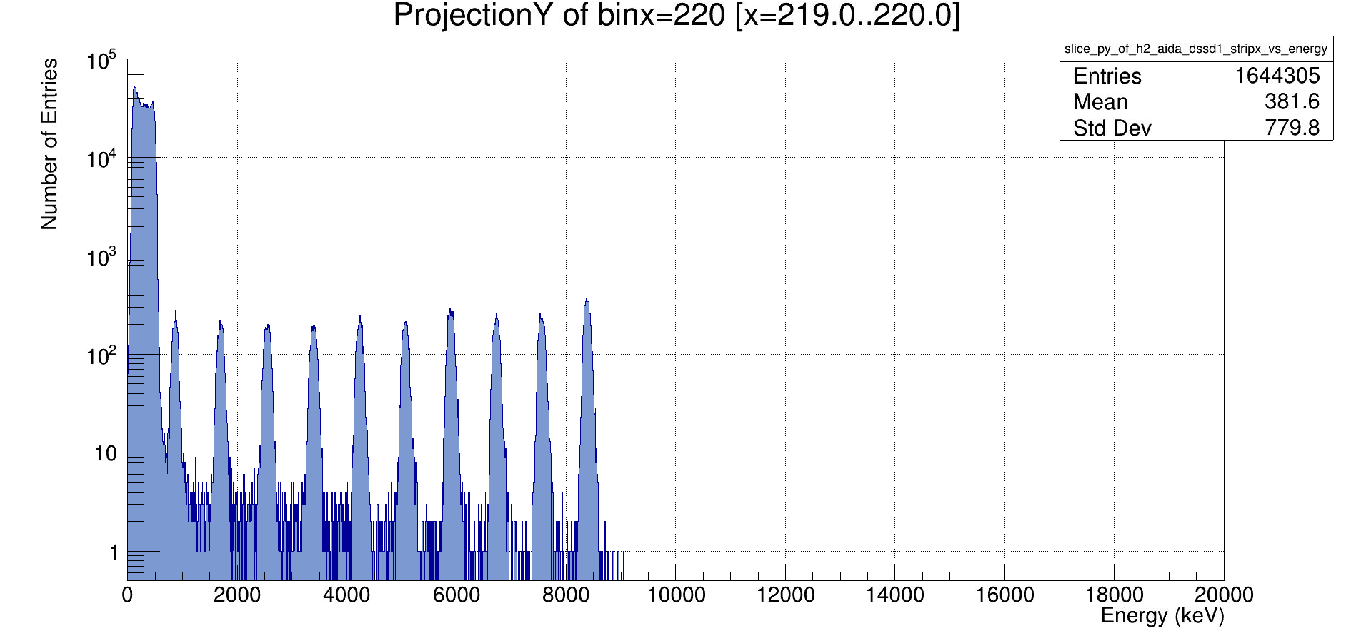
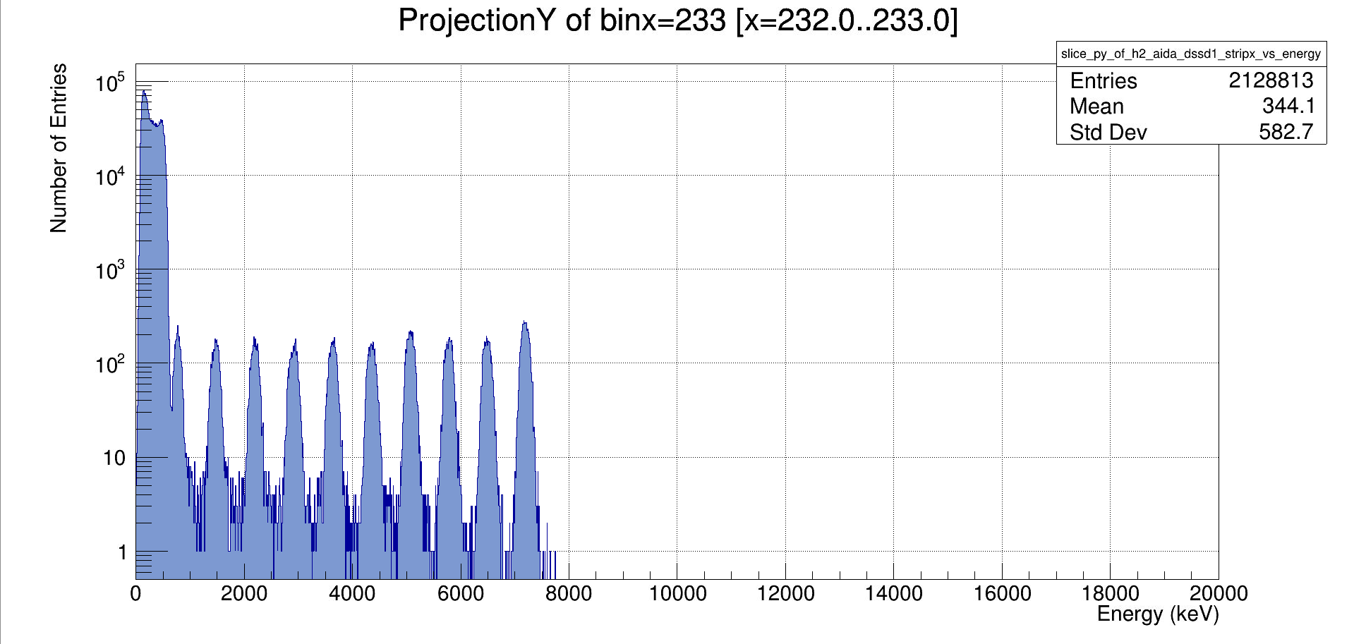
Initial analysis of the raw ADC spectra can be seen in attachment 4 & 5. |
| Attachment 1: Screenshot_from_2025-11-07_13-56-34.png
|
|
| Attachment 2: Screenshot_from_2025-11-07_13-45-30.png
|
|
| Attachment 3: Screenshot_from_2025-11-07_13-43-50.png
|
|
| Attachment 4: Screenshot_2025-11-07_192947.png
|
|
| Attachment 5: Screenshot_2025-11-07_193005.png
|
|
|
699
|
Thu Feb 20 17:06:42 2025 |
JB, CC, TD,MP | WR error for aida 13,14,15,16 |
WR timestamp errors resolved after reseating the HDMI cables to the MACB |
|
531
|
Fri Mar 8 16:05:57 2024 |
JB, CC, TD, NH | Friday 8 March |
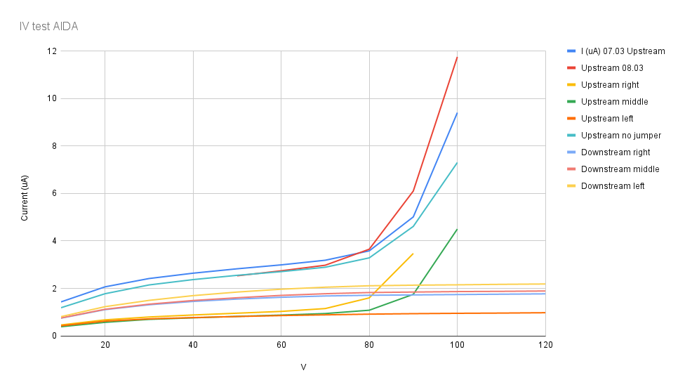
Bias tests of AIDA on individual wafers and in parallel. Spreadsheet can be found in attachment 1, and graphic results can be seen in Attachment 2. Summary: Upstream detector cannot be biased in parallel nor individually. Downstream detector can be biased with positively and each wafer can individually be biased negatively. In parallel, it was not possible to bias the downstream detector negatively as indicated by the tests below.
Test downstream DSSSD with positive polarity bias
Configuration as follows:
CAEN N1419ET ch #3 connected to LHS FEE64 adaptor PCB ( looking upstream ) - LK1 *not* fitted LK1 fitted to 3x ( top )
FEE64 adaptor PCBs Lemo 00.250 jumper cables from/to GND terminals of 3x ( top )
FEE64 adaptor PCBs *and* LHS FEE64 adaptor PCB 1x ( bottom, middle )
FEE64 adaptor PCB connected to ribbon cables but not otherwise connected to anything, LK3 fitted Total 5x adaptor PCBs installed
No other LKs fitted
| Bias Voltage (V) |
Current (uA) |
| +10 |
2.150 |
| +20 |
3.300 |
| +30 |
4.035 |
| +40 |
4.550 |
| +50 |
4.955 |
| +60 |
5.255 |
| +70 |
5.490 |
| +80 |
5.650 |
| +90 |
5.730 |
| +100 |
5.780 |
| +110 |
5.825 |
| +120 |
5.860 |
Nominal V-I curve, stable leakage current. Attachment 3.
Following this success we attempted to repeat test using negative polarity bias
Configuration as follows:
CAEN N1419ET ch #1 connected to ( top, left )
FEE64 adaptor PCB ( looking upstream ) LHS
FEE64 adaptor PCB ( looking upstream ) - LK1 fitted Lemo 00.250 jumper cables from/to BIAS terminals of 3x ( top )
FEE64 adaptor PCBs Lemo 00.250 jumper cable from/to GND terminals of LHS and ( top, left )
FEE64 adaptor PCBs 1x ( bottom, middle )
FEE64 adaptor PCB connected to ribbon cables but not otherwise connected to anything,
LK3 fitted Total 5x adaptor PCBs installed No other LKs fitted With detector bias
-20V we continue to observe the leakage current cycling between 0 and ~2uA with a frequency ~1Hz ( as before )
Copy configuration used for upstream DSSSD test ( which was successful albeit there was detector breakdown at bias voltages > c. 90V )
CAEN N1419ET ch #1 connected to ( bottom, left )
FEE64 adaptor PCB ( looking upstream ) LHS
FEE64 adaptor PCB ( looking upstream ) - LK1 fitted Lemo 00.250 jumper cables from/to BIAS terminals of 3x ( bottom )
FEE64 adaptor PCBs Ground cable jumpered from/to GND terminals LHS, ( left, bottom ), RHS and all 3x top FEE64 adaptor PCBs ( bottom, middle )
FEE64 adaptor PCB LK3 fitted Total 8x adaptor PCBs installed
No other LKs fitted With detector bias -20V we observe leakage current of ~2-3uA.
Current unstable - variations 10-100nA over periods of several seconds Although the leakage current is unstable this is an improvement over previous tests with negative bias. The duplication of upstream and downstream configurations suggests that for some unknown reason it is necessary to connect all 8x FEE64 adaptor PCBs whereas our expectation was that only 4x were necessary.
Summary: Upstream DSSSD Si wafers 1 & 2 breakdown for bias > c. 90V Si wafer 3 OK to 120V Positive bias - not tested Negative bias OK - leakage current stable to c. 90V Downstream DSSSD Si wafers 1, 2 & 3 OK to 120V Positive bias OK Negative bias - leakage current unstable
To do:
1) Disconnect ribbon cables from p+n junction FEE64 adaptor PCBs of upstream DSSSD, apply c. 100V bias and check leakage current is zero i.e. eliminate shorts in PCBs
2) Check that all ribbon cables are properly seated in the adaptor PCBs
3) Check all adaptor PCB connector pins are OK: will need to remove ribbon cables
4) If/when you open check seating of all Kapton PCBs in the DSSSD connectors *and* carefully check that ribbon cable and Kapton PCB connectors are aligned and not out by 1 or 2 rows say.
|
| Attachment 1: IV_test_AIDA.xlsx
|
| Attachment 2: chart.png
|
|
| Attachment 3: Downstream_positive_bias_vs._Current_(uA).png
|
.png.png)
|
|
566
|
Mon Apr 8 16:39:00 2024 |
JB, CC, TD | Monday 8 April |
17.32 Power and detector bias cycle

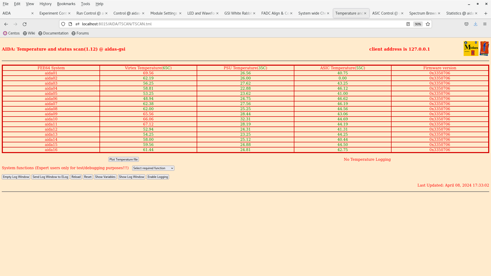
      DSSSD bias & leakage current OK - attachment 1

      FEE64 temperatures OK - attachment 2
       *except* aida02 ASIC temp u/s

      ASIC settings 2024Mar27-11.25.32
       slow comparator p+n FEE64s 0xa (100keV), n+n FEE64s 0xf (150keV)

      BNC PB-5 pulser
      amplitude 10.0V
      attenuation x10
      frequency 25Hz
      polarity -
      tau_d 1ms
      tail pulse

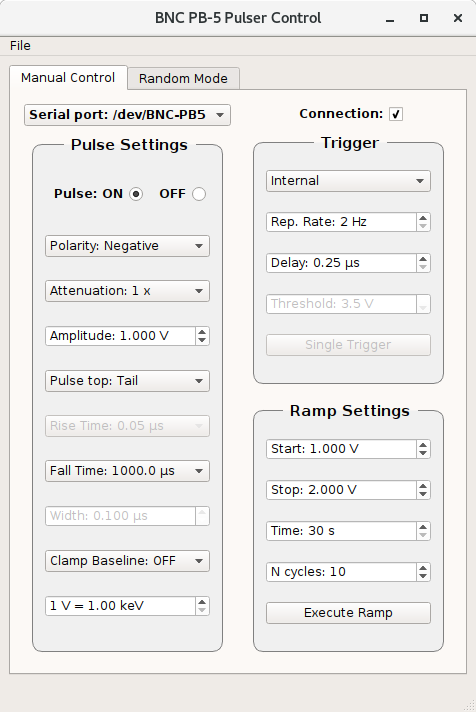
      test - distributed by daisy chain to n+n FEE64s - chain terminated by 50 Ohm - currently connected to pulser

      test + distributed by daisy chain to p+n FEE64s - chain terminated by 50 Ohm - currently disconnected from pulser

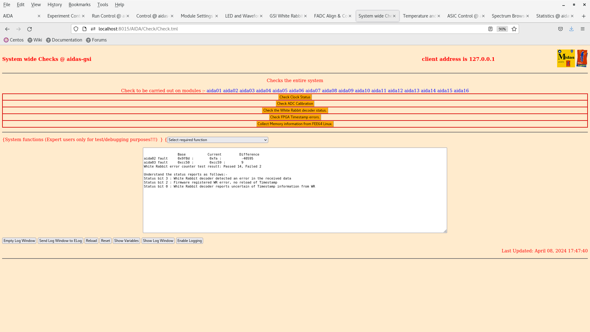
      All system wide checks OK *except* aida02 & aida03 WR decoder status errors - attachment 10

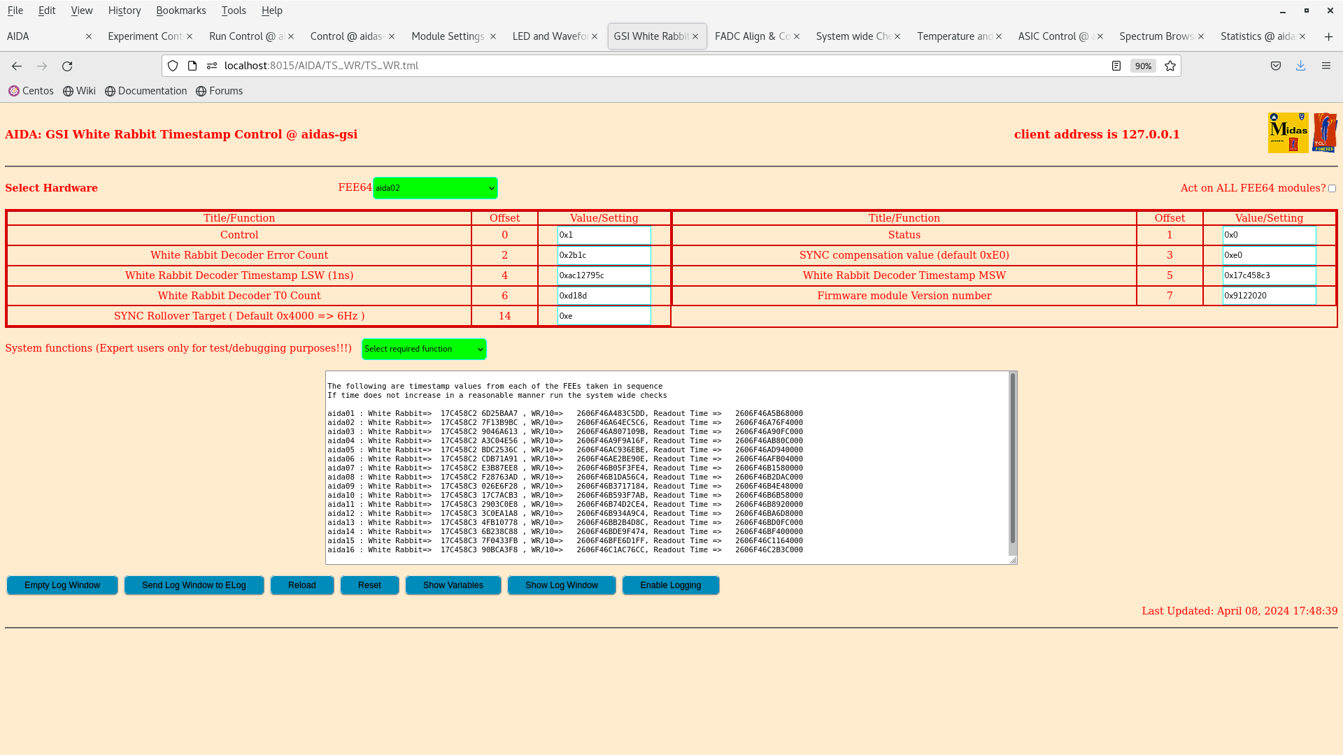
      WR timestamps OK - attachment 11

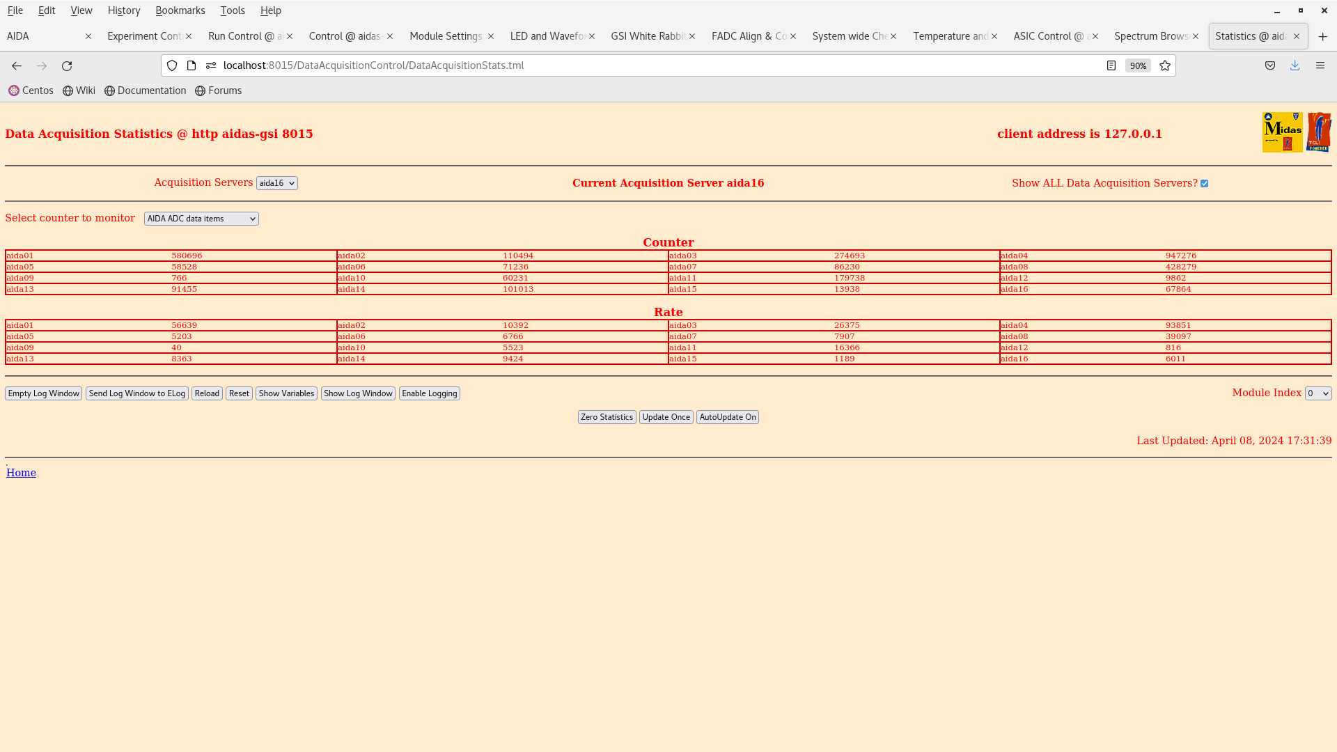
      ADC data item stats - attachment 3
       12 of 16 < 20k, all < 100k

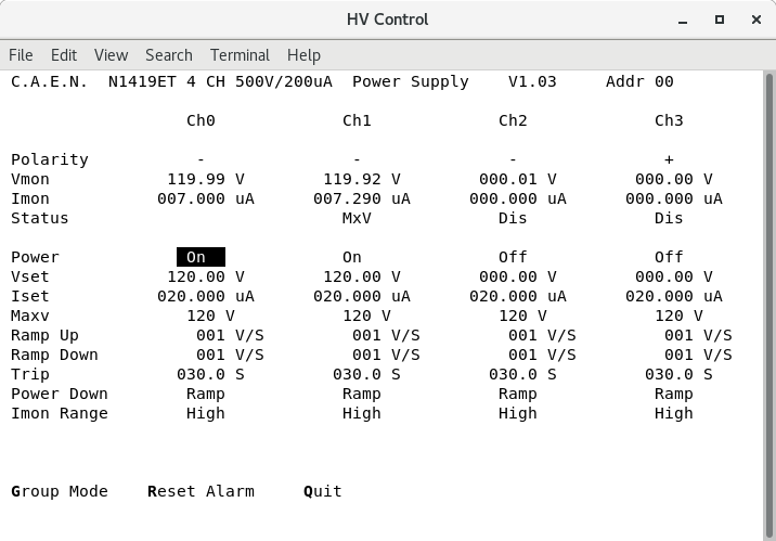
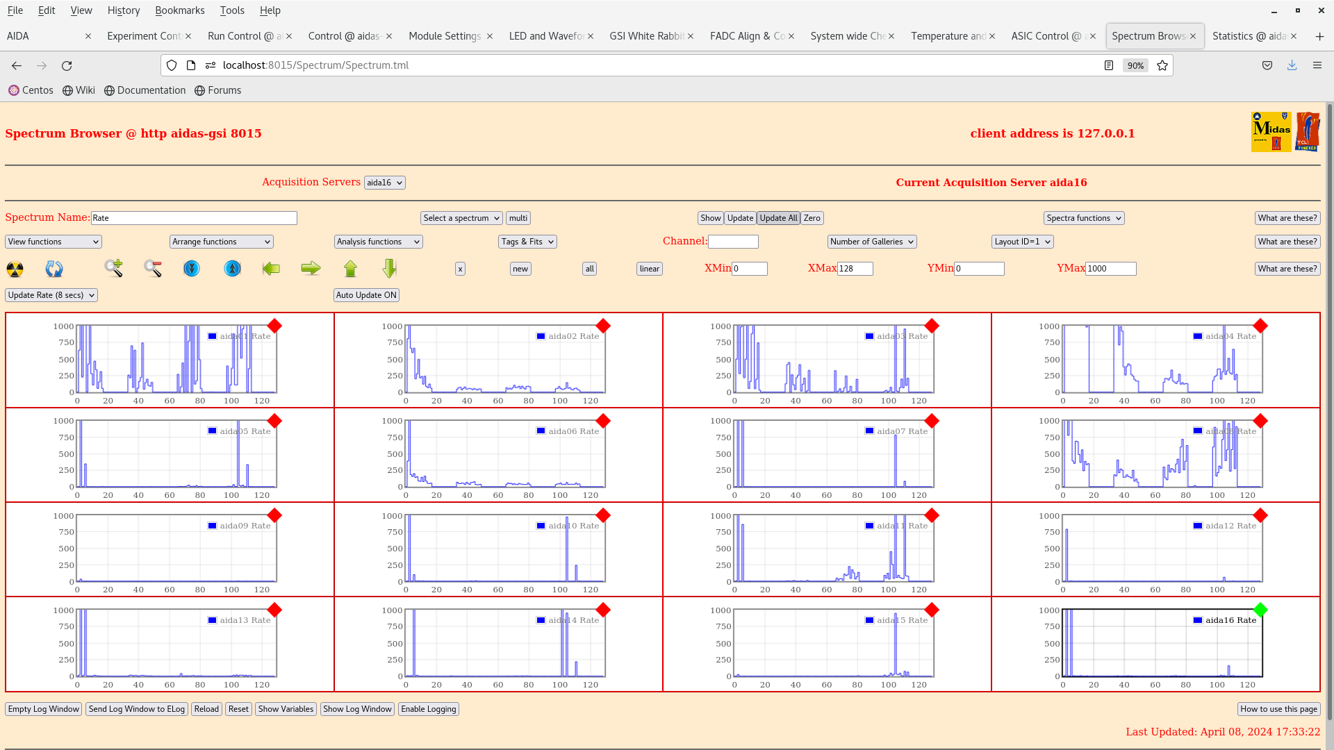
      per FEE64 Rate spectra - attachment 4

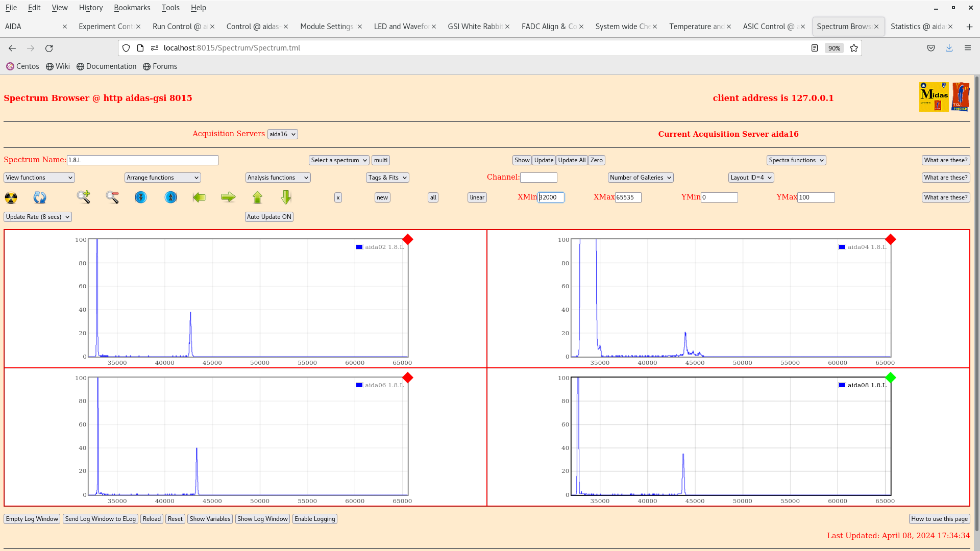
      per n+n FEE64 1.8.L spectra - attachment 5

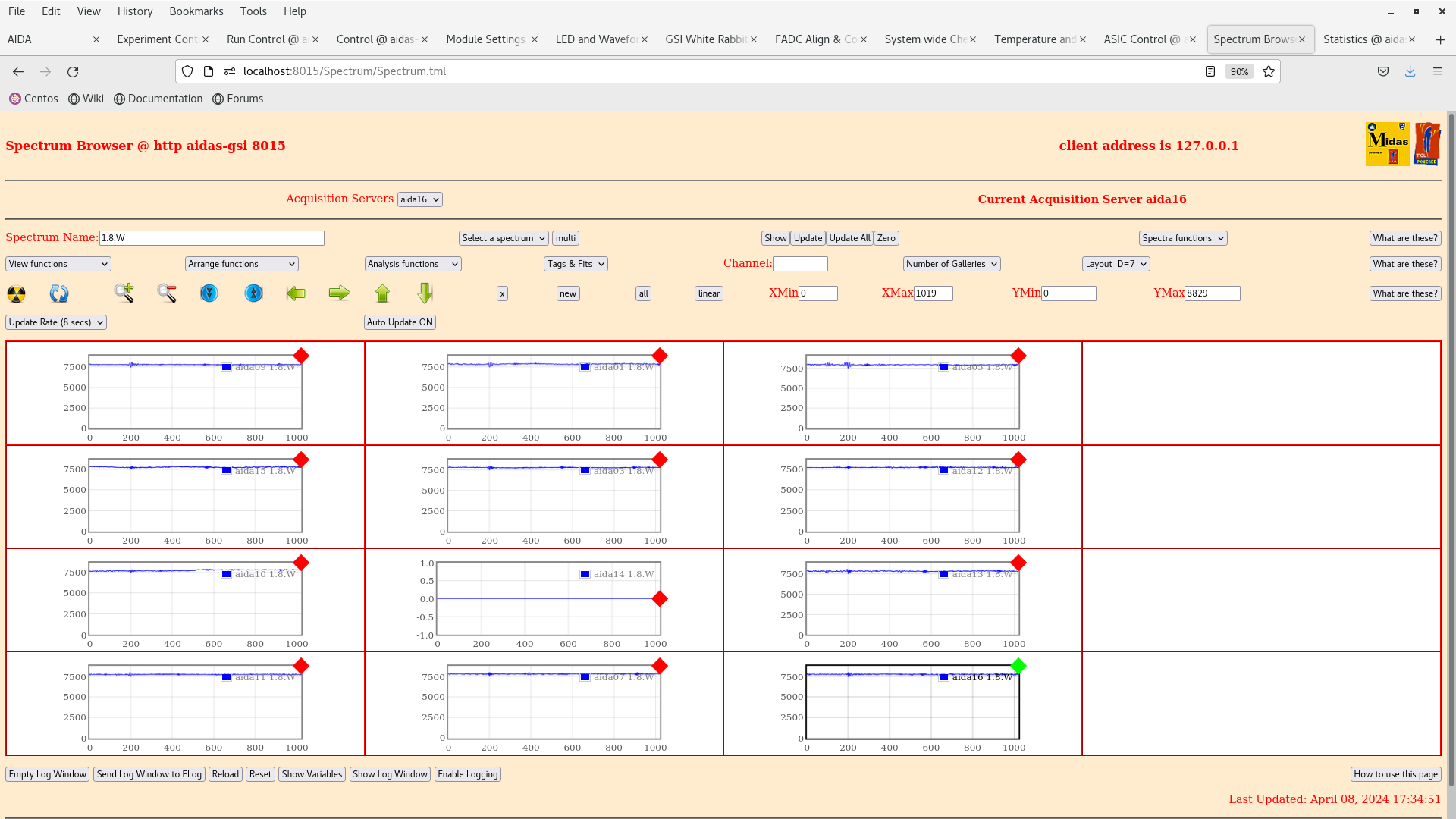
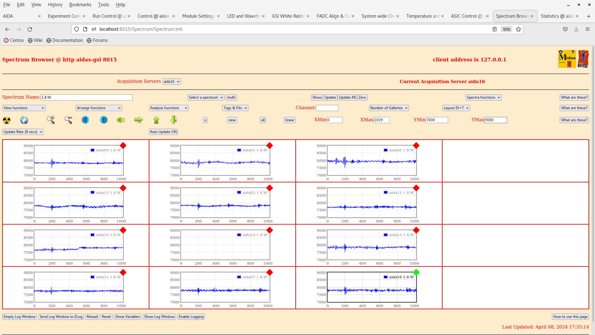
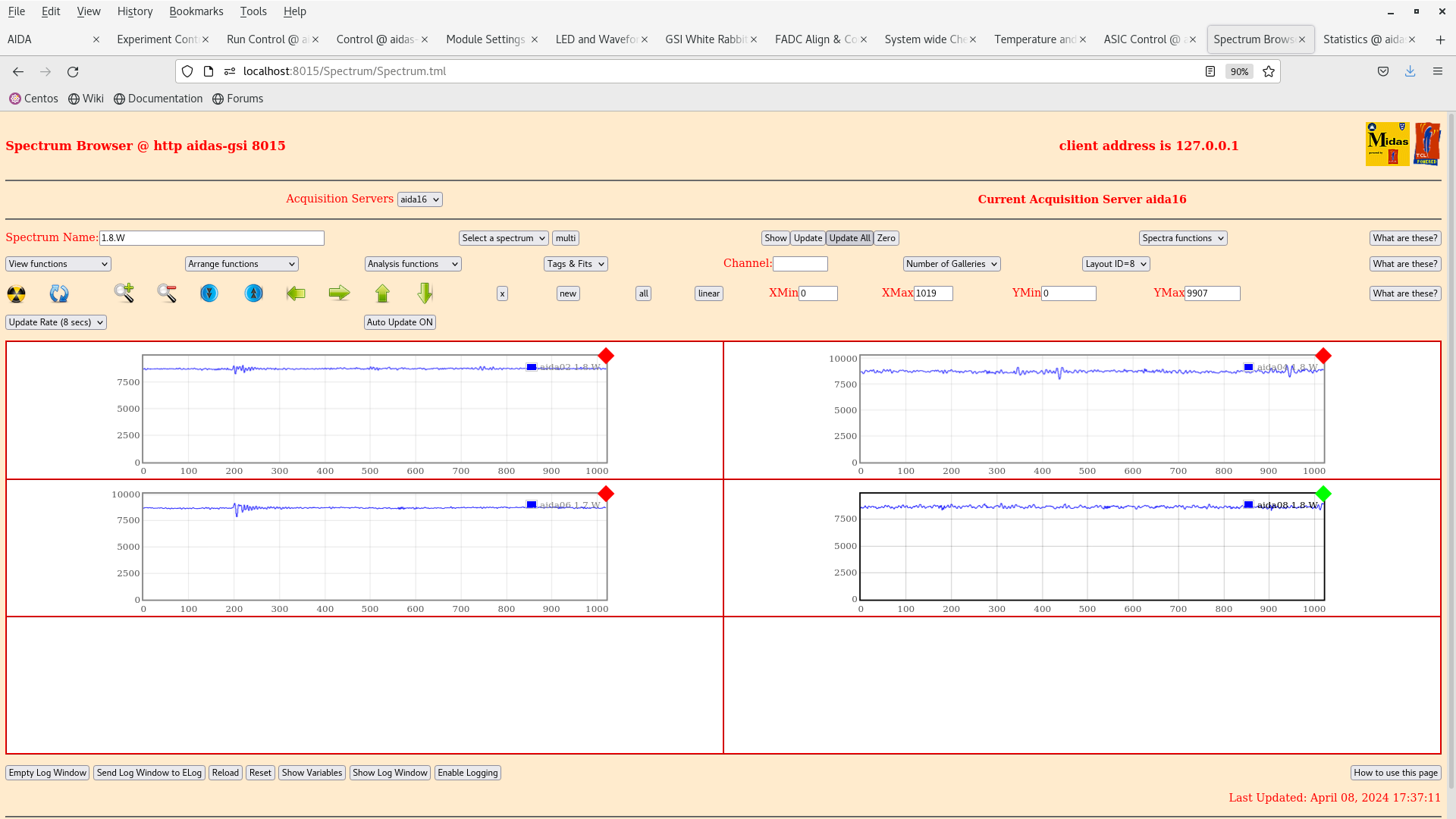
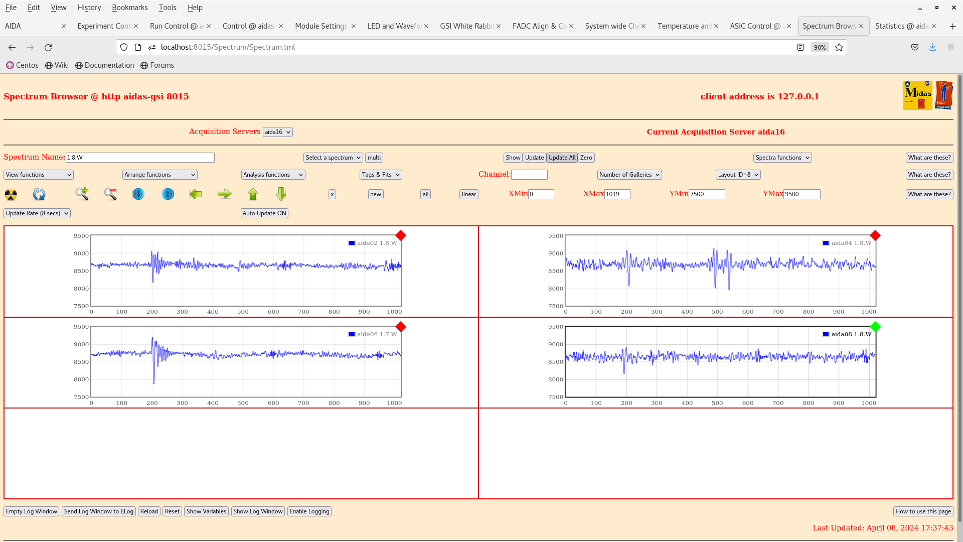
      1.8.W spectra - 20us FSR - attachments 6-9
       preamplifier output noise generally very good

*Current ground configuration*

CAEN N1419ET LK fitted (non floating outputs)

ground cable from aida04-aida12-aida02-aida09-aida01-aida05
HV#0 aida12-aida03-aida15

ground cable from aida08-aida16-aida06-aida10-aida14-aida13
HV#1 aida16-aida07-aida11

LK3 fitted aida03, aida07

LK1 fitted aida02, aida04, aid06, aida08

test - distributed by daisy chain to n+n FEE64s - chain terminated by 50 Ohm - currently connected to pulser

test + distributed by daisy chain to p+n FEE64s - chain terminated by 50 Ohm - currently disconnected from pulser

all DSSSD ribbon cable drain wires grounded to their resepctive AIDA adaptor PCBs

JB observed open circuit between AIDA Al snout and AIDA support frame ( as expected )

AIDA PSU cabling as reported https://elog.ph.ed.ac.uk/DESPEC/560

Snout configuration:

- all bPlast cables are disconnected and floating.
- CC taped up all the cables and exit points in snout.
- CC, JB covered the exit of the snout with two additional layers of aluminium foil which were also taped shut.


To Do:

- repower detector, see if similar conditions persist.
- disconnect test - pulser, again see if conditions persist.

- aida04 asic#1 investigate noise
- aida14 asic #1 & asic #2 u/s? replace ASIC mezzanine?
|
| Attachment 1: Screenshot_from_2024-04-08_17-32-49.png
|
|
| Attachment 2: Screenshot_from_2024-04-08_17-33-10.png
|
|
| Attachment 3: Screenshot_from_2024-04-08_17-33-14.png
|
|
| Attachment 4: Screenshot_from_2024-04-08_17-33-33.png
|
|
| Attachment 5: Screenshot_from_2024-04-08_17-34-40.png
|
|
| Attachment 6: Screenshot_from_2024-04-08_17-35-00.png
|
|
| Attachment 7: Screenshot_from_2024-04-08_17-35-19.png
|
|
| Attachment 8: Screenshot_from_2024-04-08_17-37-28.png
|
|
| Attachment 9: Screenshot_from_2024-04-08_17-37-56.png
|
|
| Attachment 10: Screenshot_from_2024-04-08_17-48-23.png
|
|
| Attachment 11: Screenshot_from_2024-04-08_17-48-49.png
|
|
|
570
|
Wed Apr 10 08:37:57 2024 |
JB, CC, TD | Wednesday 10 April |
09.38 CC completed install of Bplast driver PCBs yesterday evening.
      All flat ribbon cables connected - all drain wires grounded
      PSU on but not enabled - return terminals grounded to PSU front panel ground
      SiPm bias off

      Water pressure and temperature OK
      FEE64 power ON

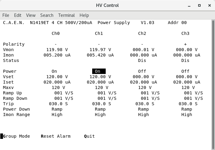
      DSSSD bias & leakage current OK - attachment 1

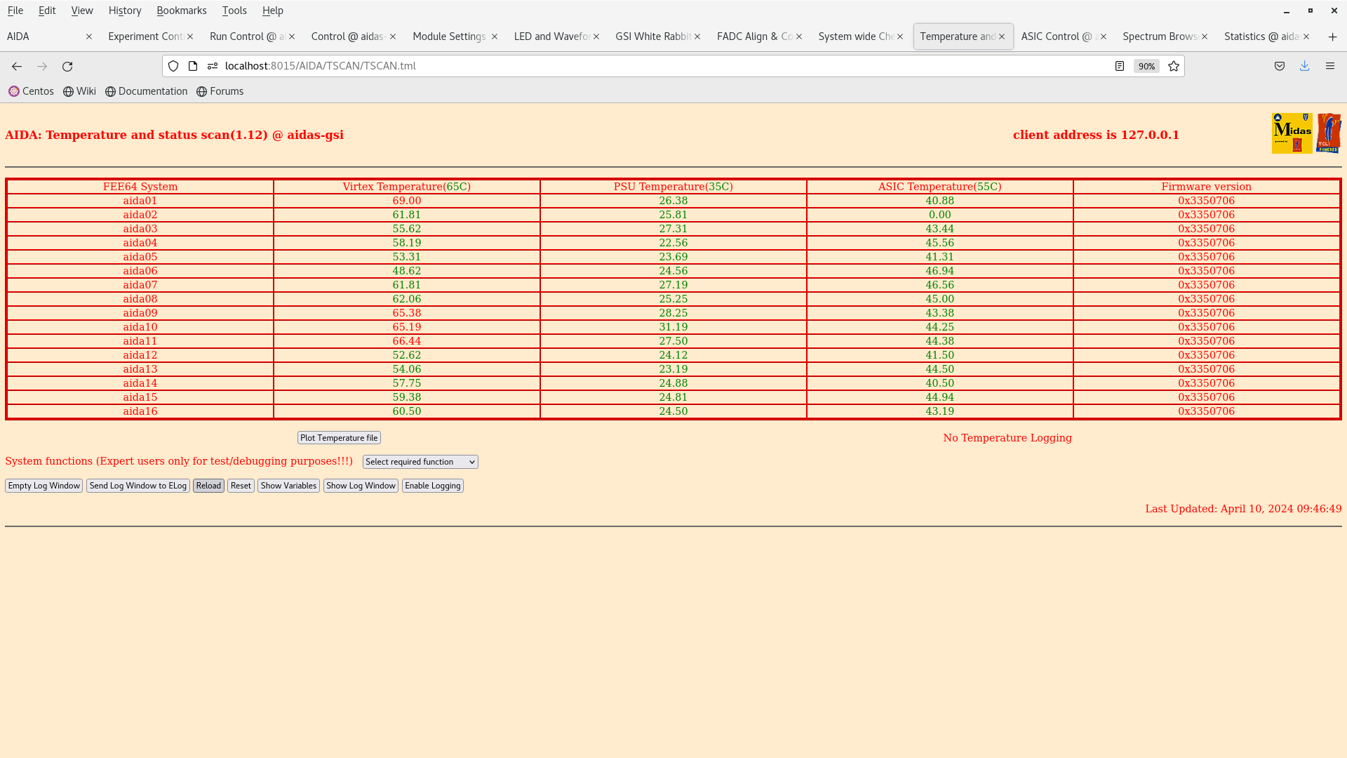
      FEE64 temps OK - attachment 2
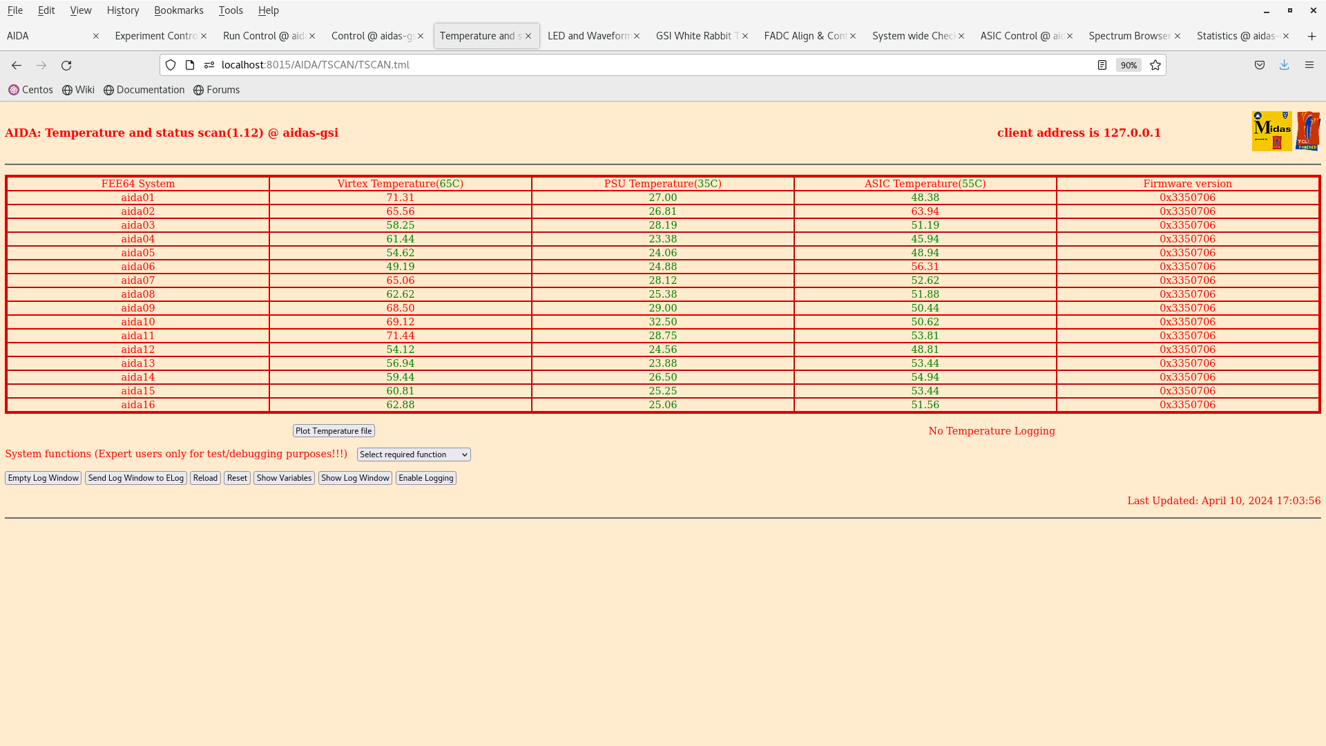
      *except* aida02 ASIC temp which is known to be u/s

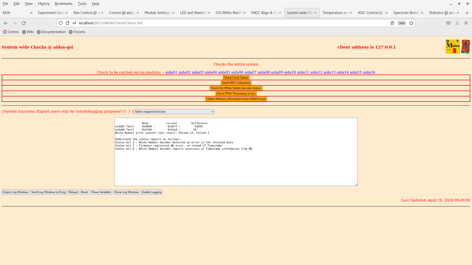
      All system wide checks OK *except* aida02 and aida03 WR decoder status - attachment 3

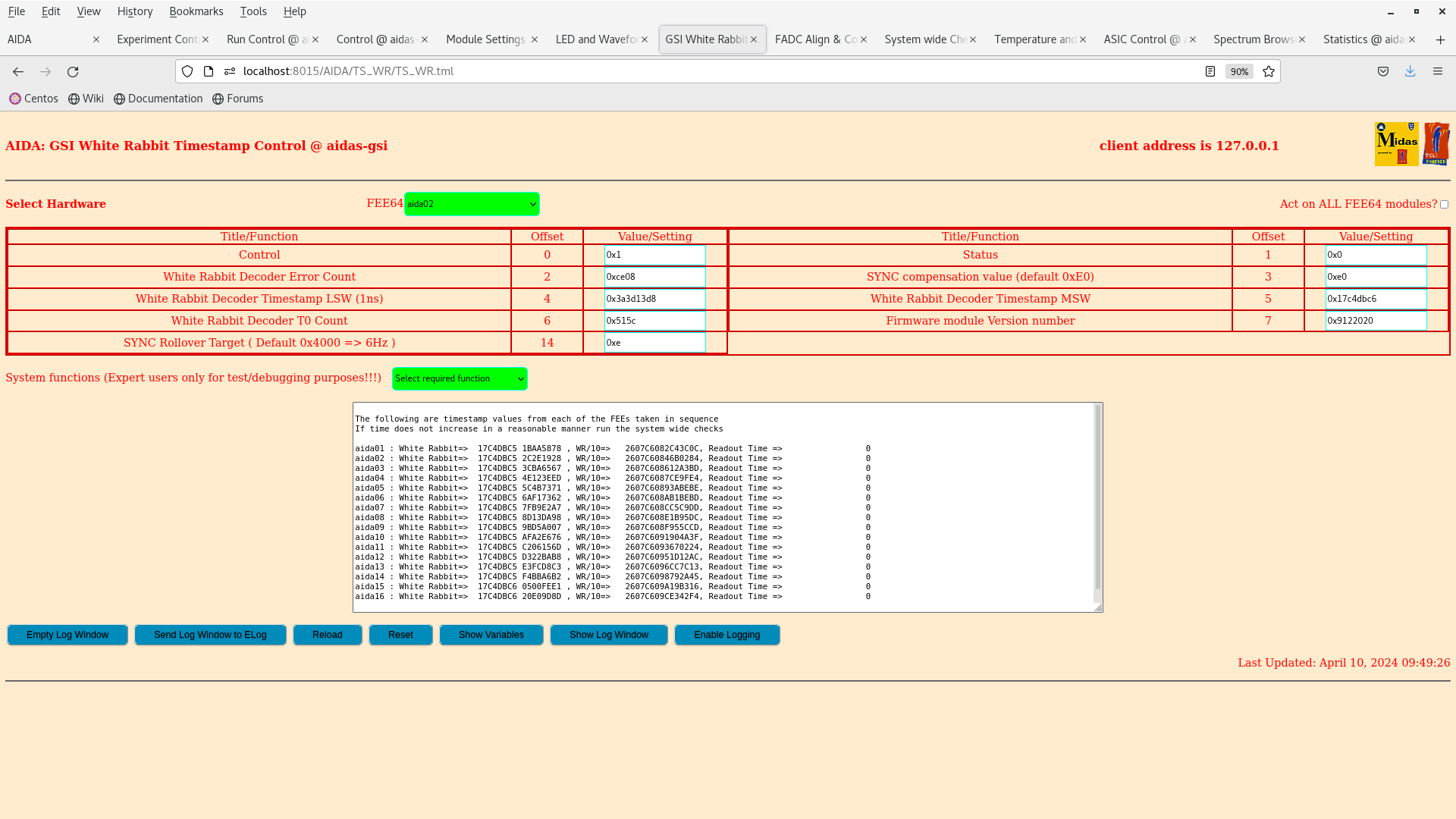
      WR timestamps OK - attachment 4

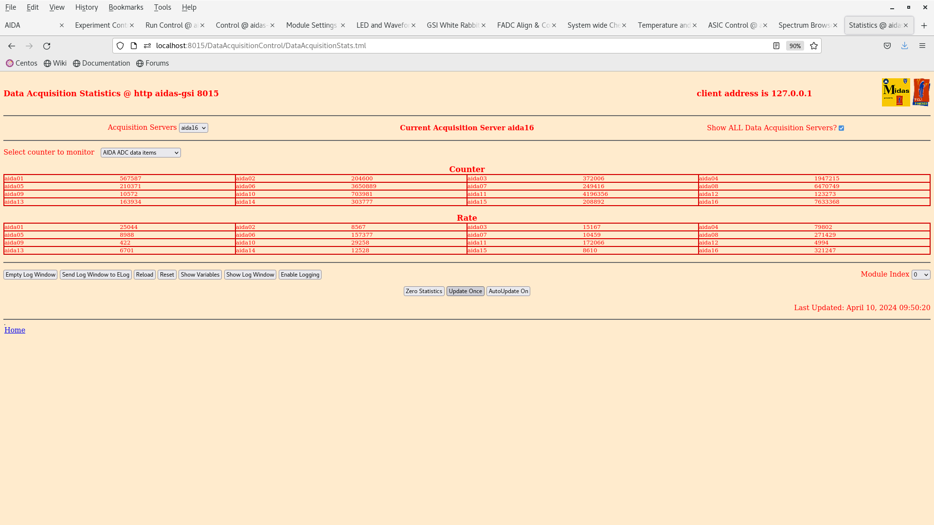
      ADC data item stats - attachments 5

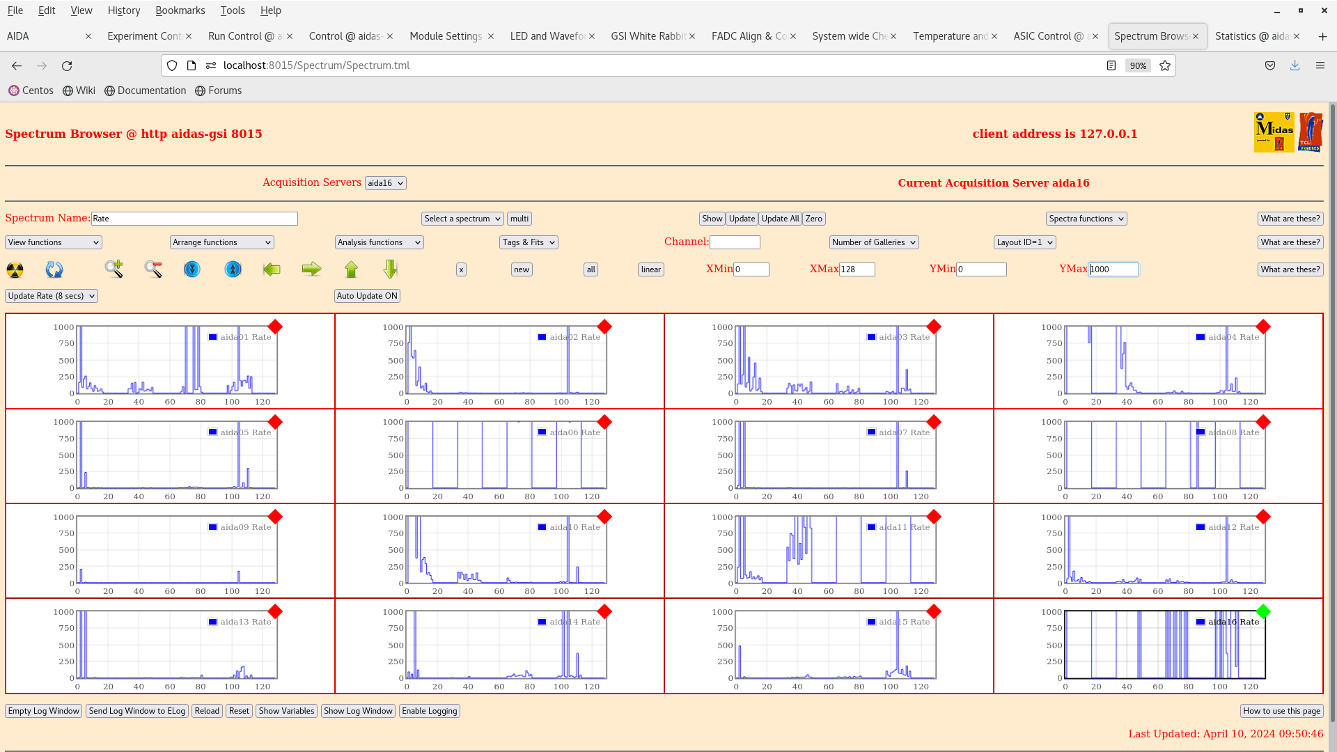
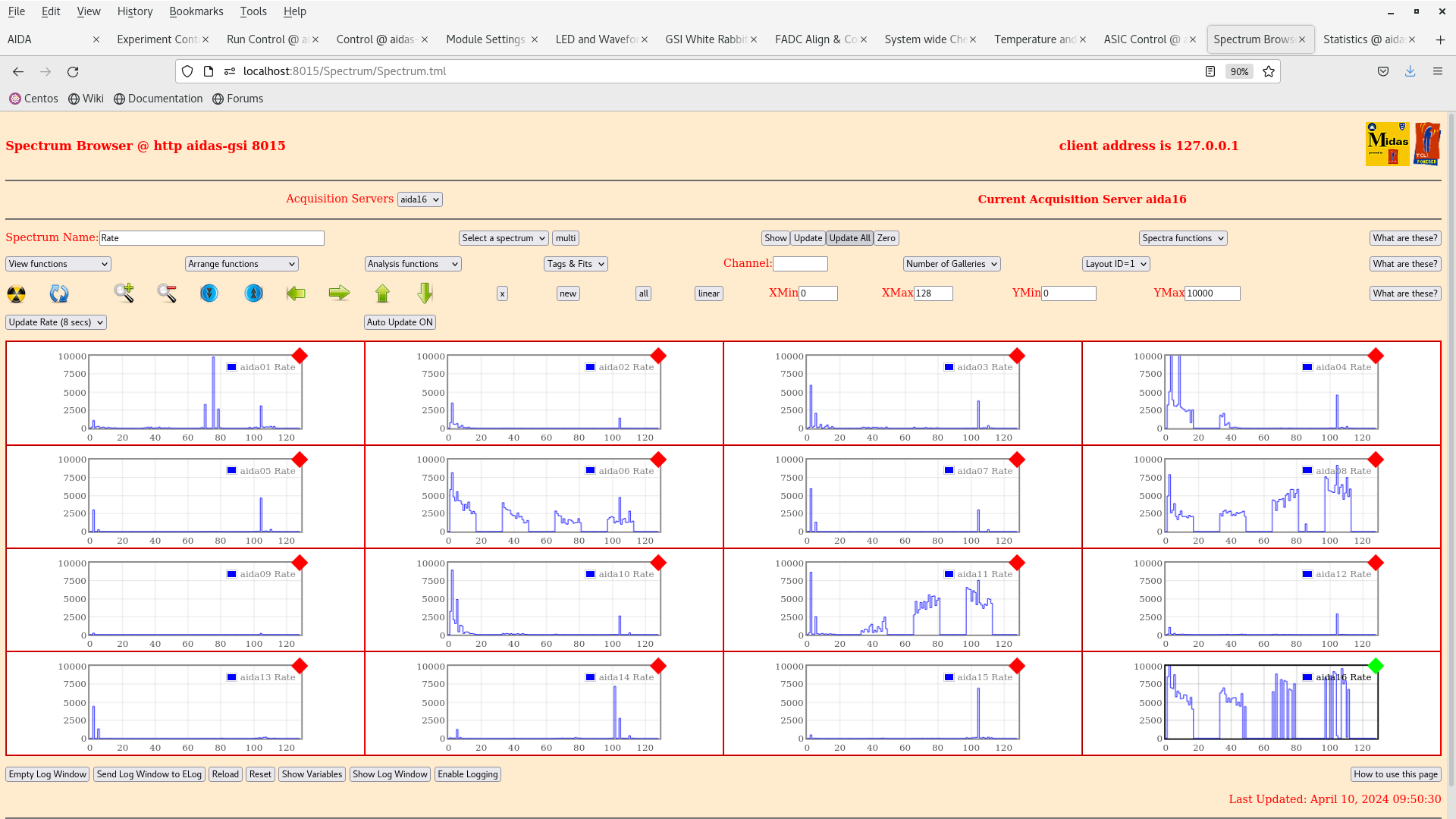
      per FEE64 Rate spectra - attachments 6-7

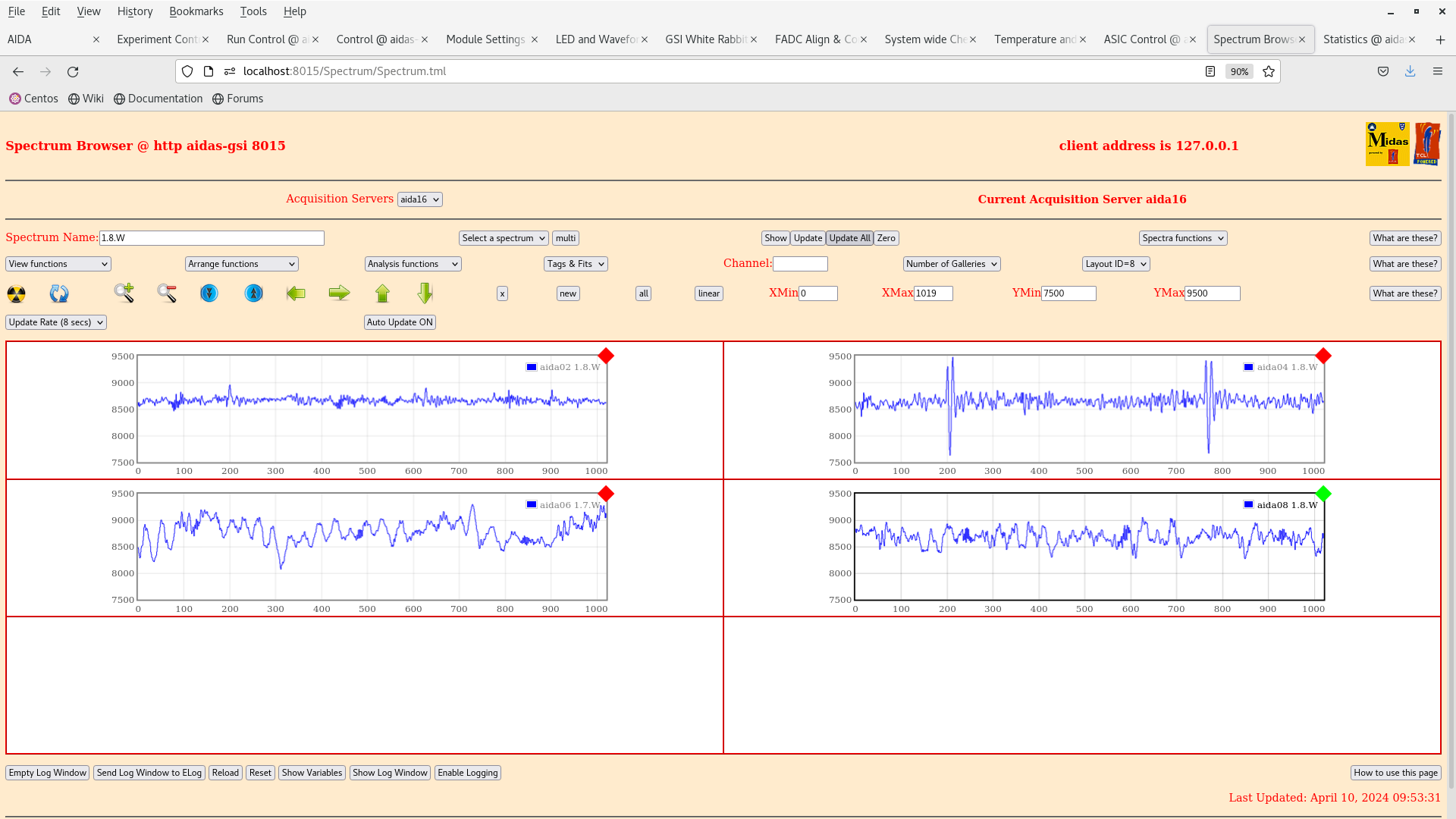
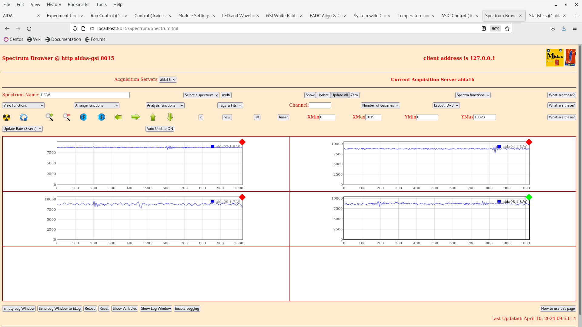
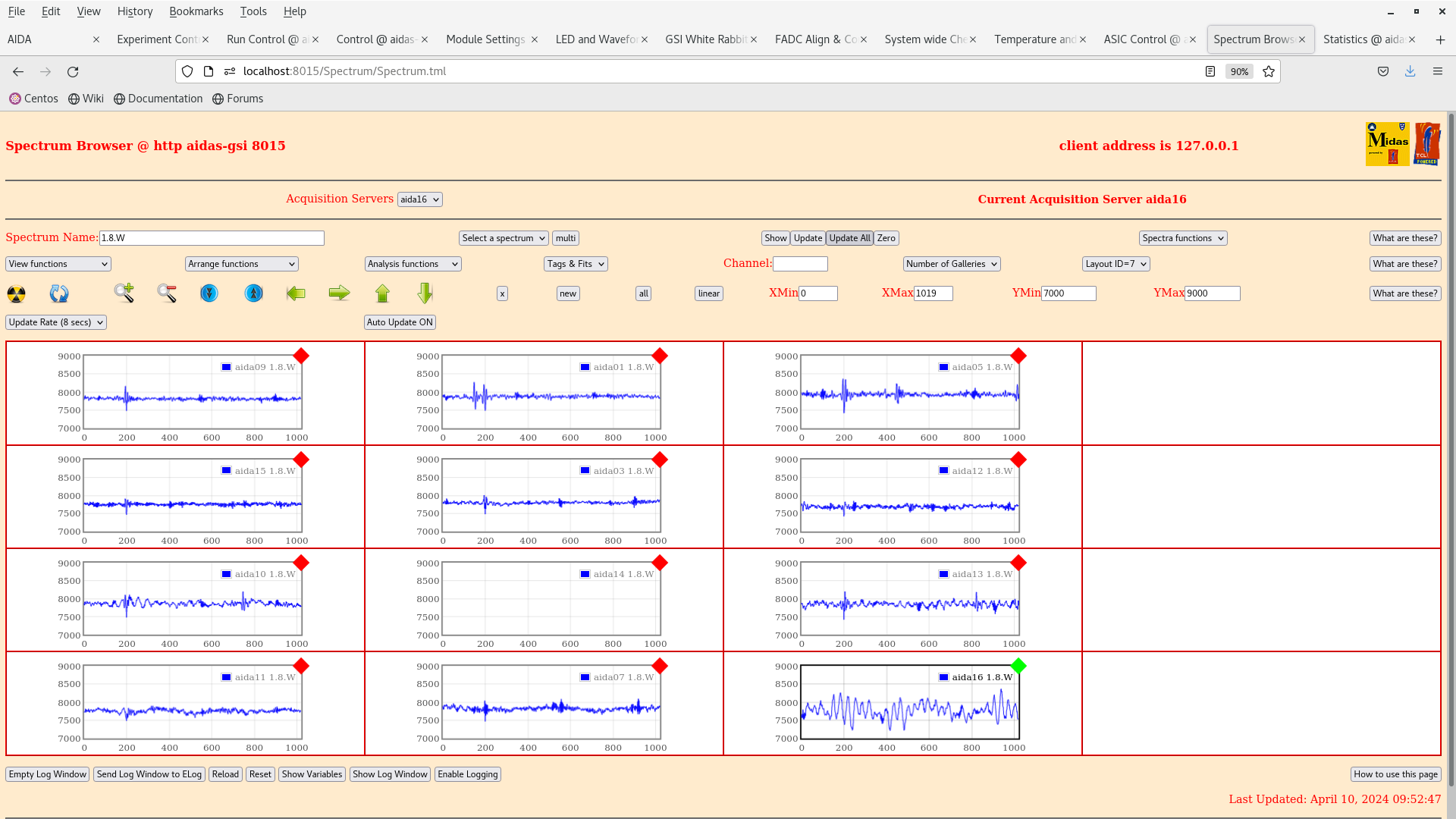
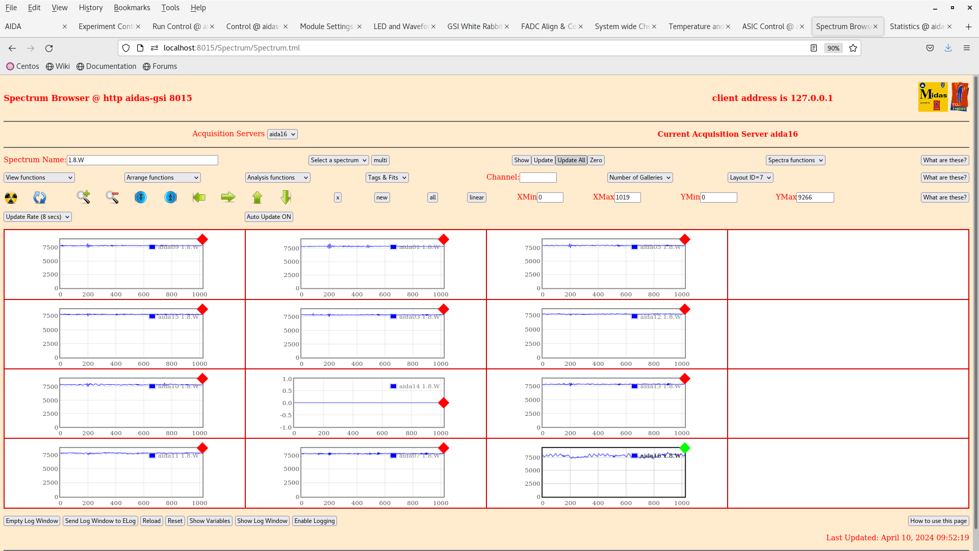
      per 1.8.W spectra - 20us FSR - attachments 8-11

      ASIC settings 2024Mar27-11.25.32
       LEC slow comparator p+n FEE64s 0xa, n+n FEE64s 0xf

      BNC PB-5 pulser - attachment 12


10.45 CC returns
      bPlas ON

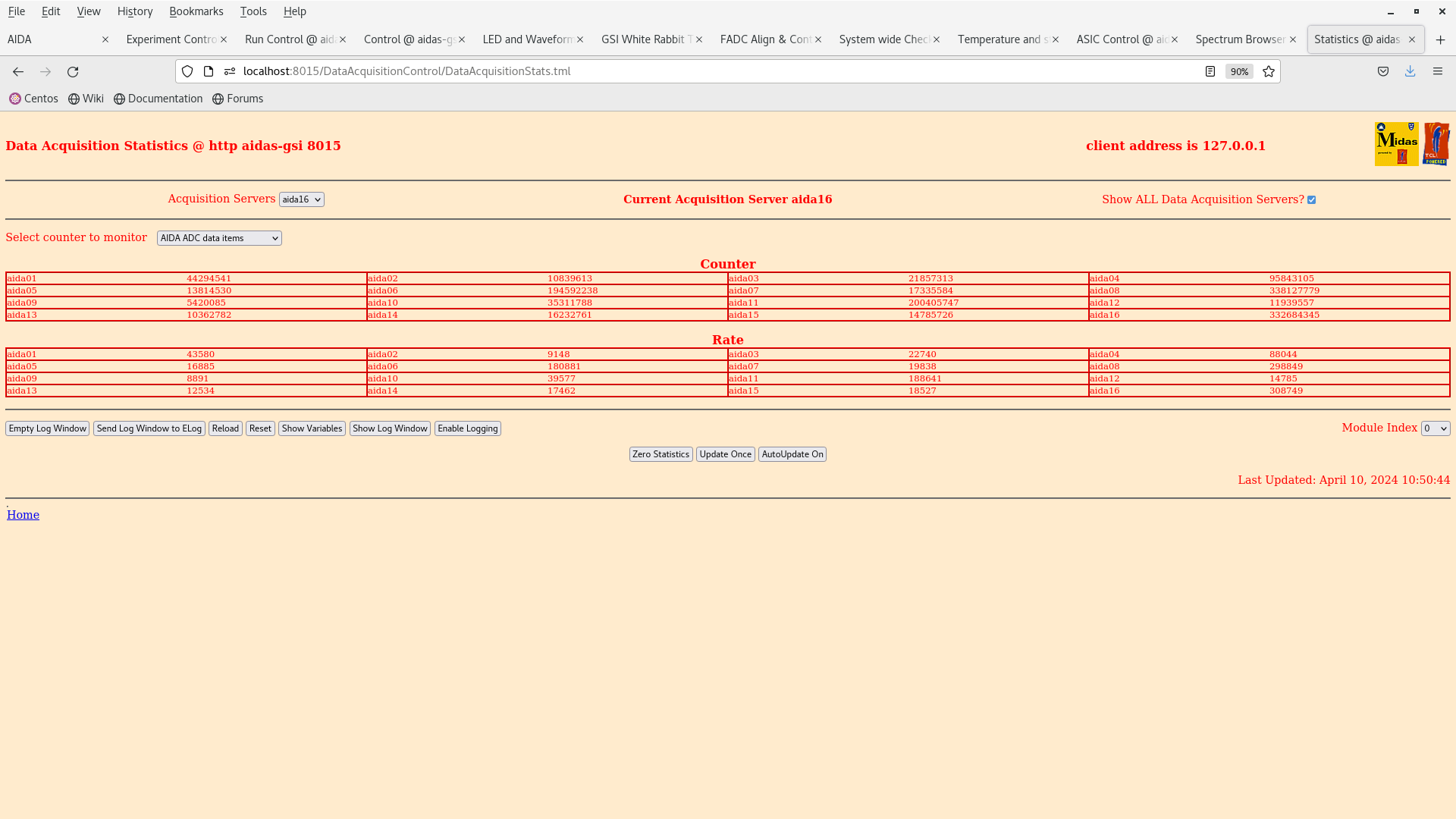
      ADC data item stats - attachments 13
       8x < 20k, max c. 310k

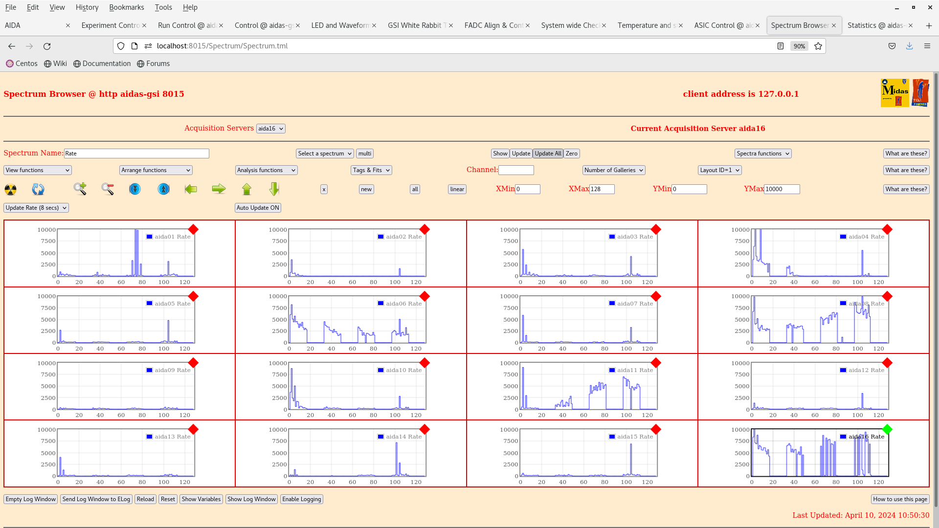
      per FEE64 Rate spectra - attachments 14

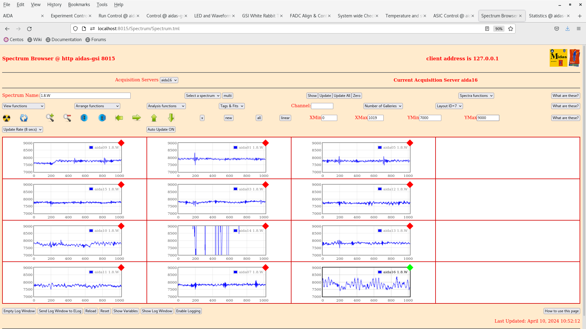
      per 1.8.W spectra - 20us FSR - attachments 15-16

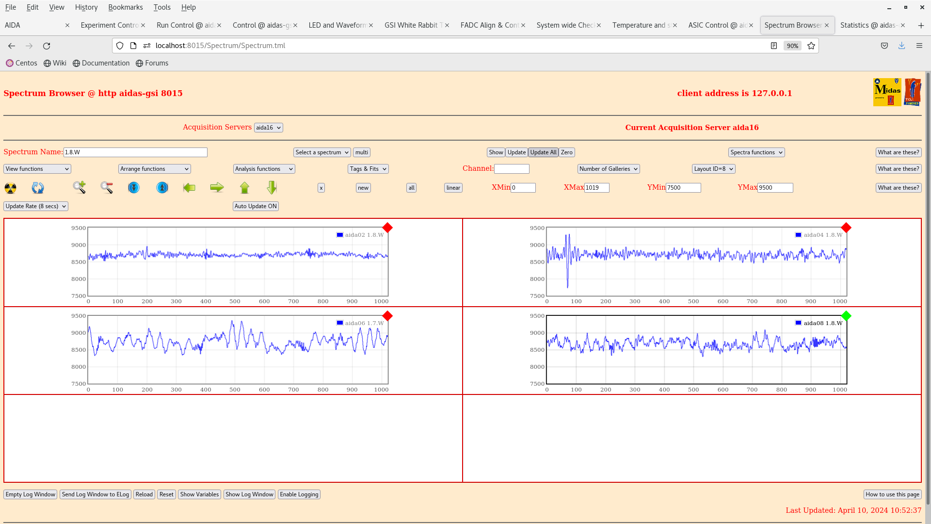
      downstream DSSSD n+n and bottom left & right p+n FEE64s noisy


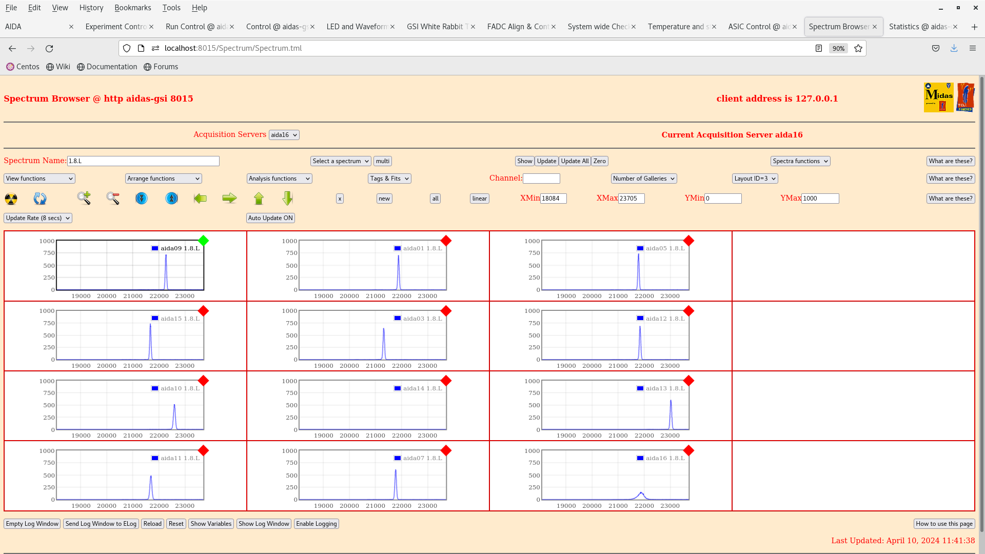
11.40 per p+n FEE64 1.8.L spectra - attachment 17
       aida09 pulser peak width 55 ch FWHM ~38keV FWHM - no change cf. before installation of bPas *except* aida16


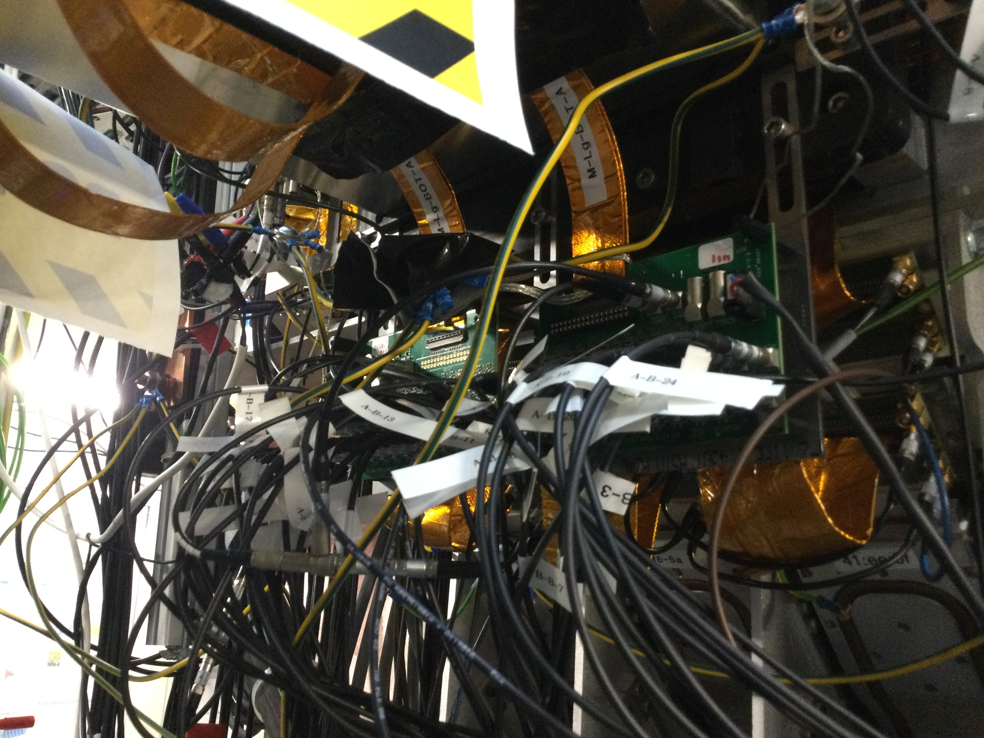
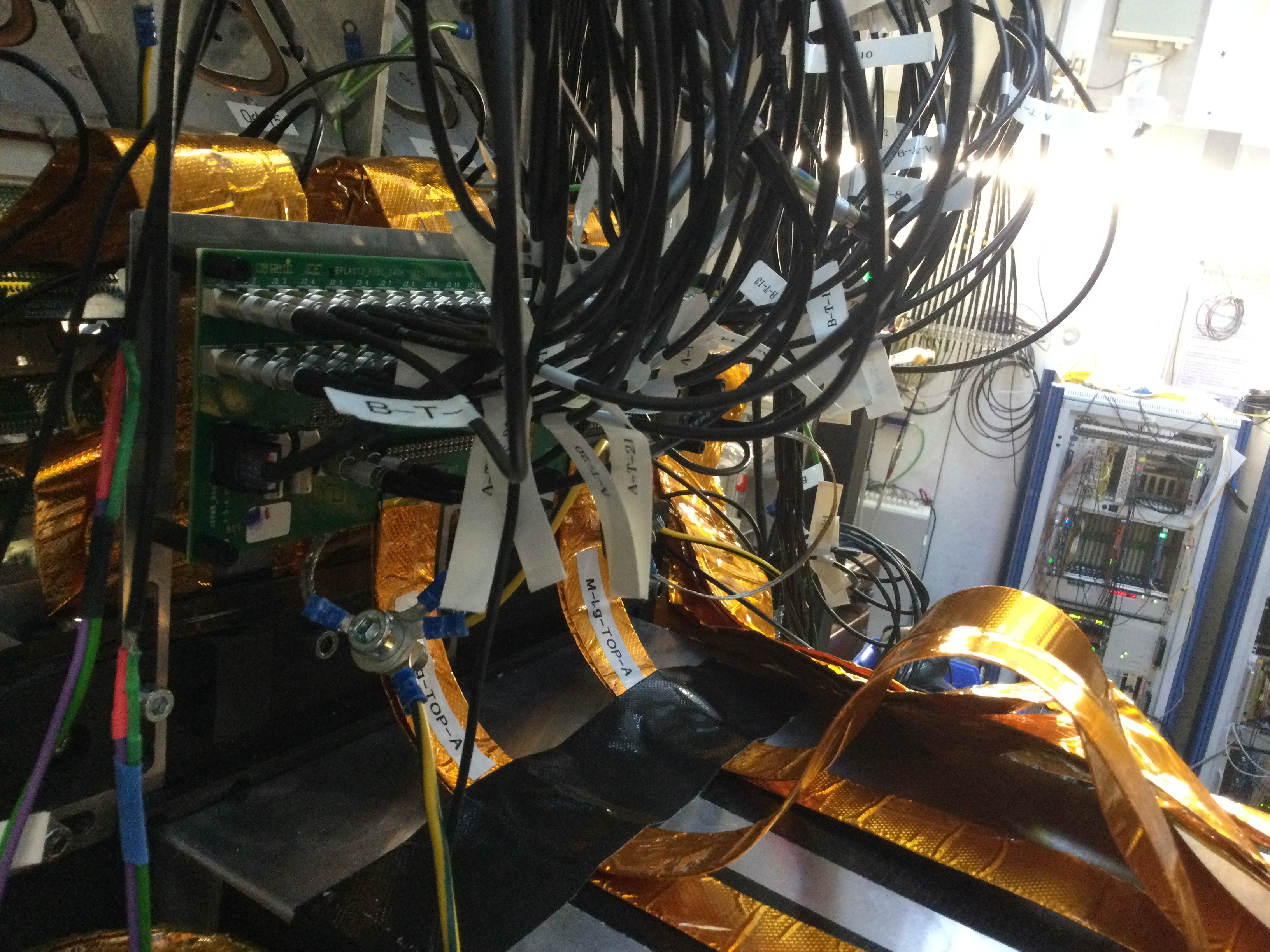
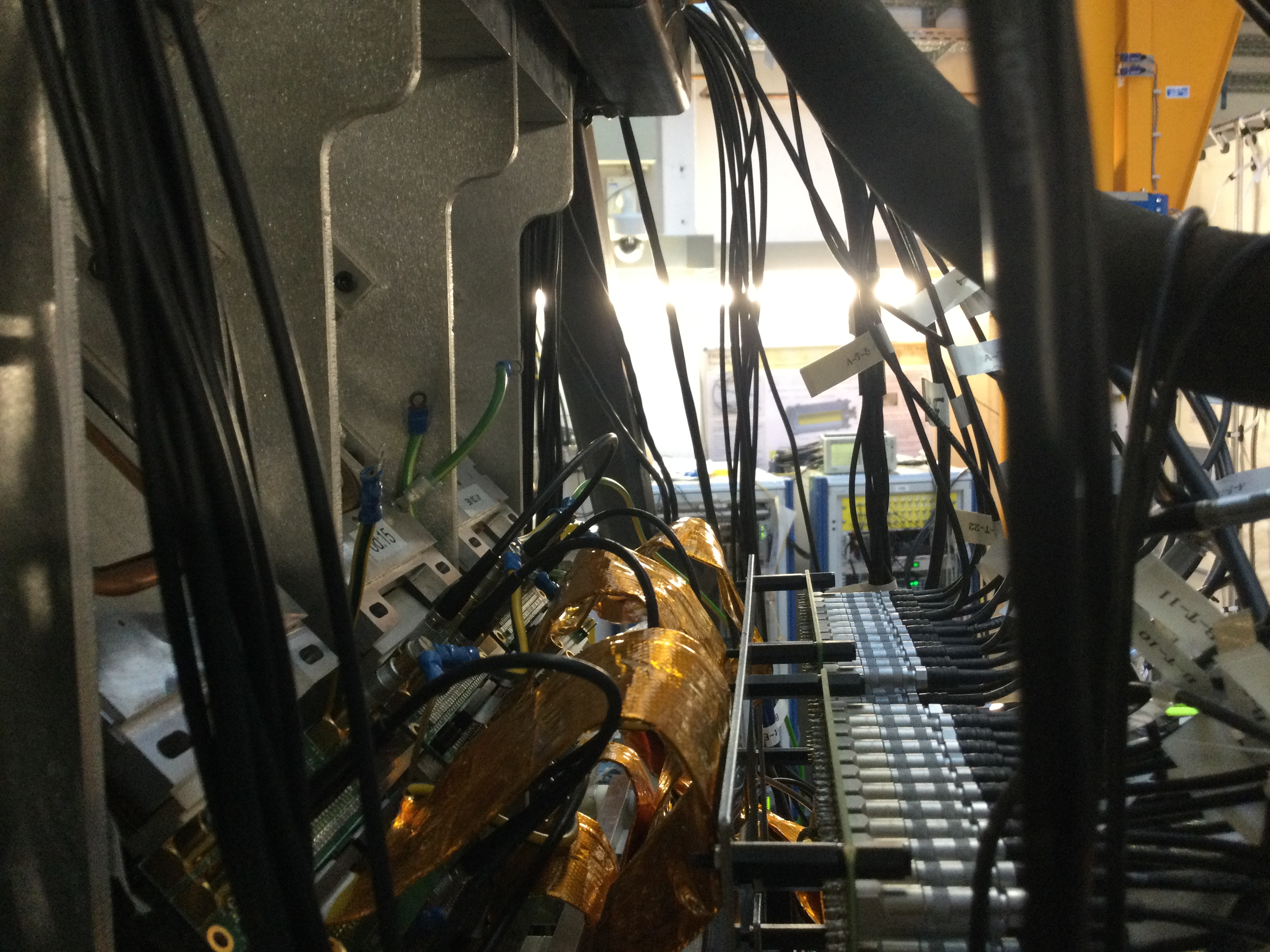
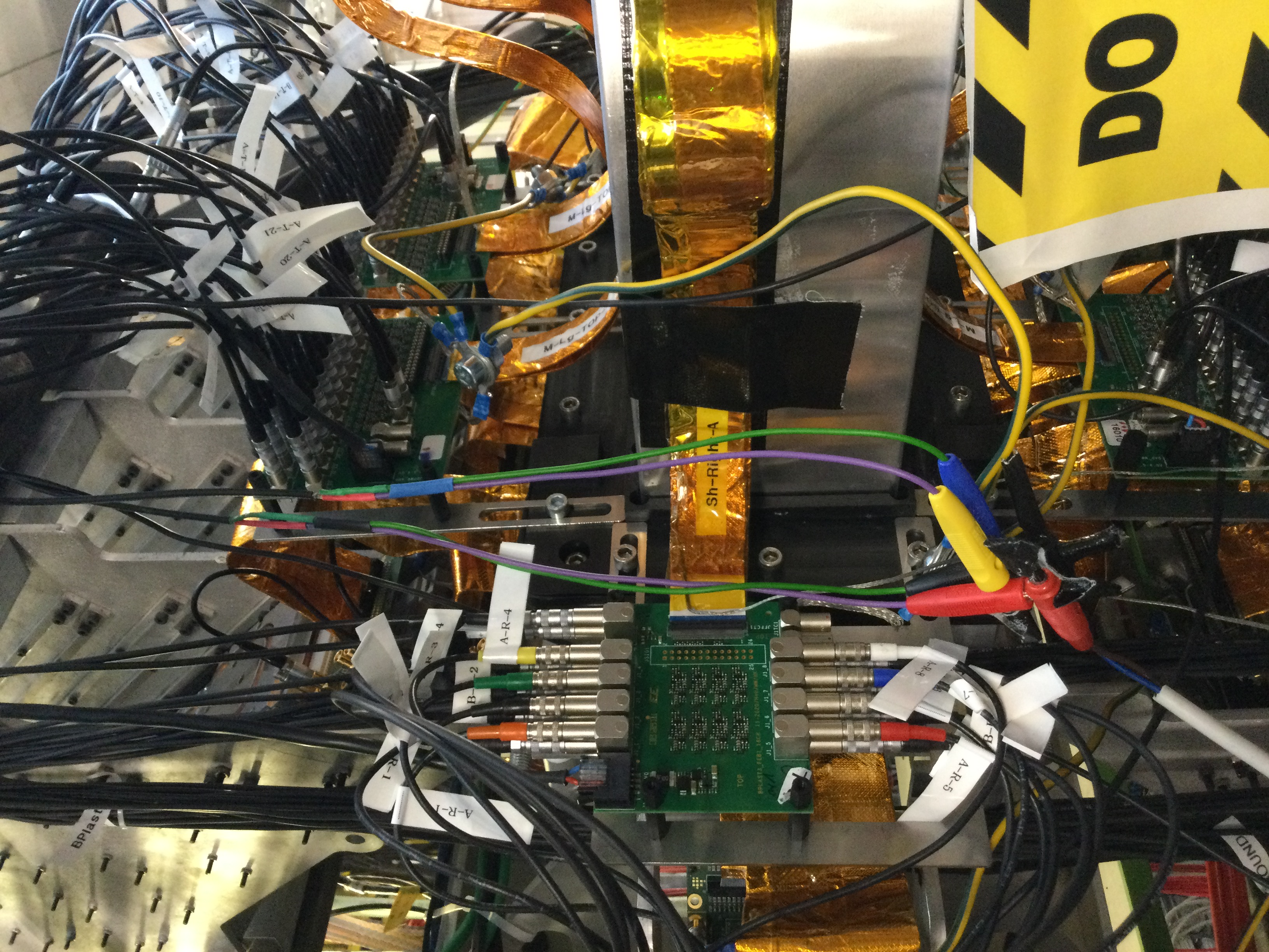
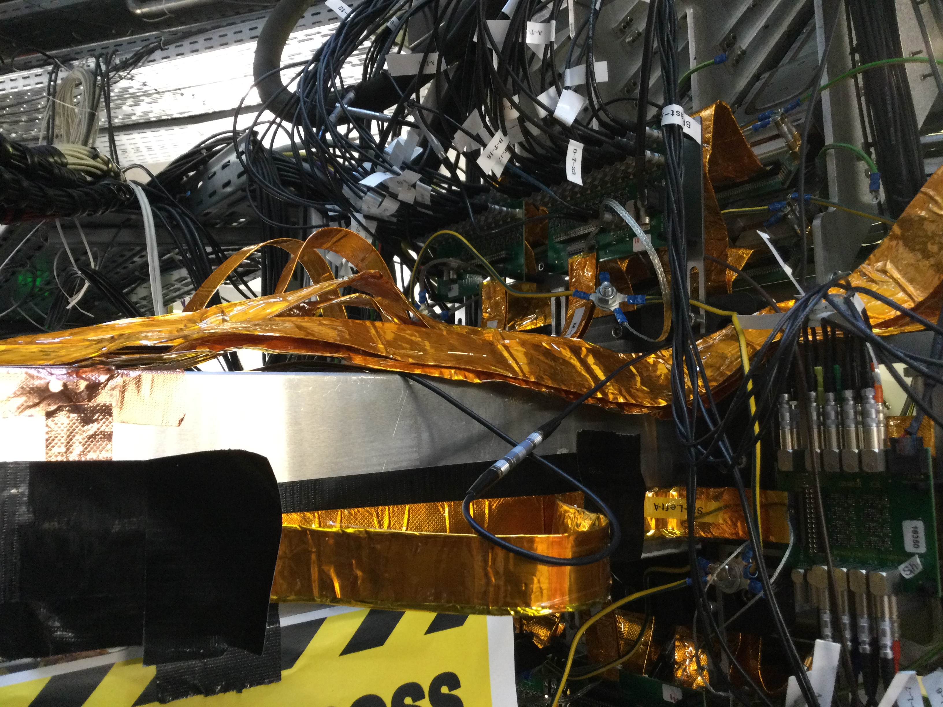
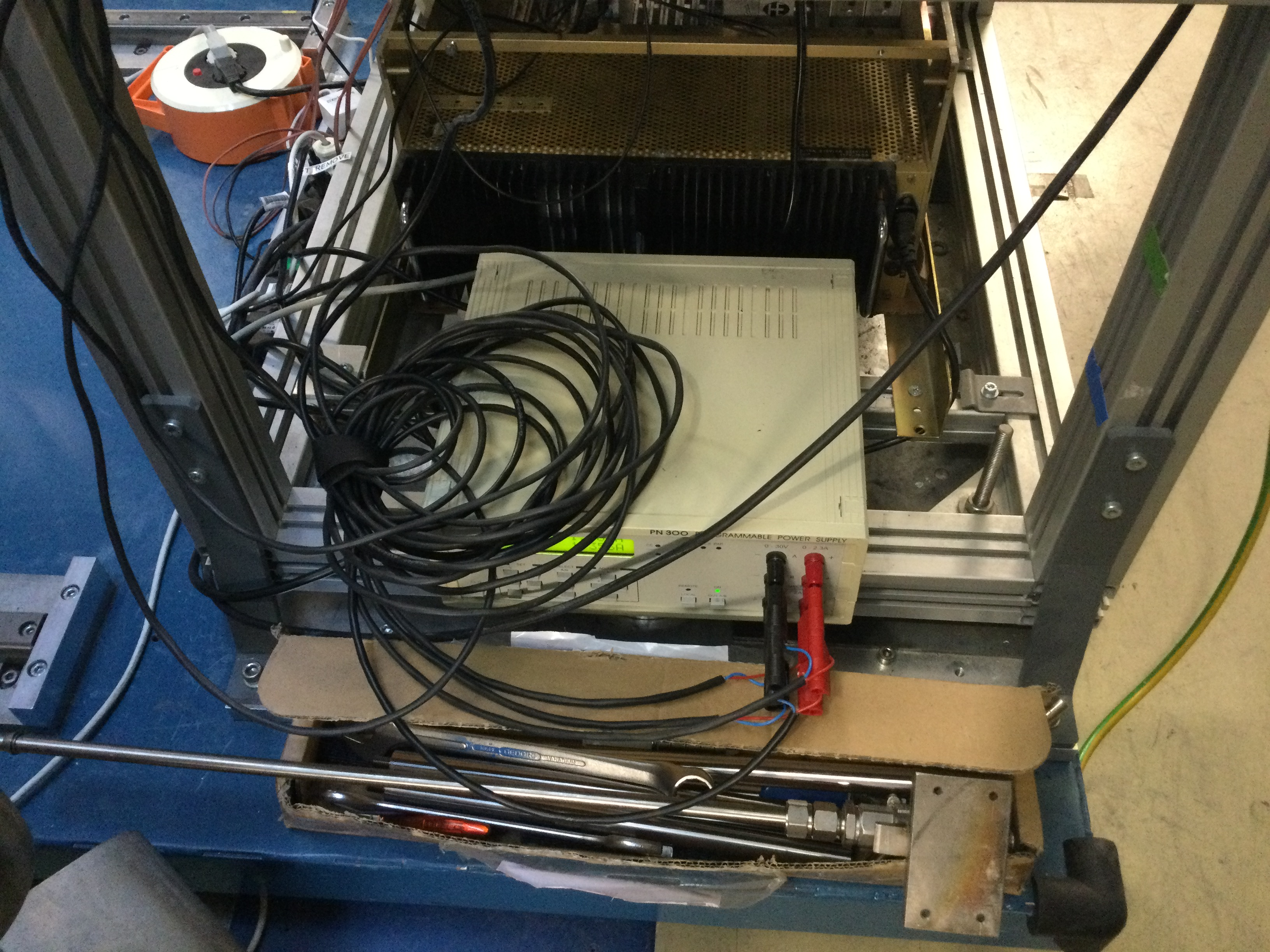
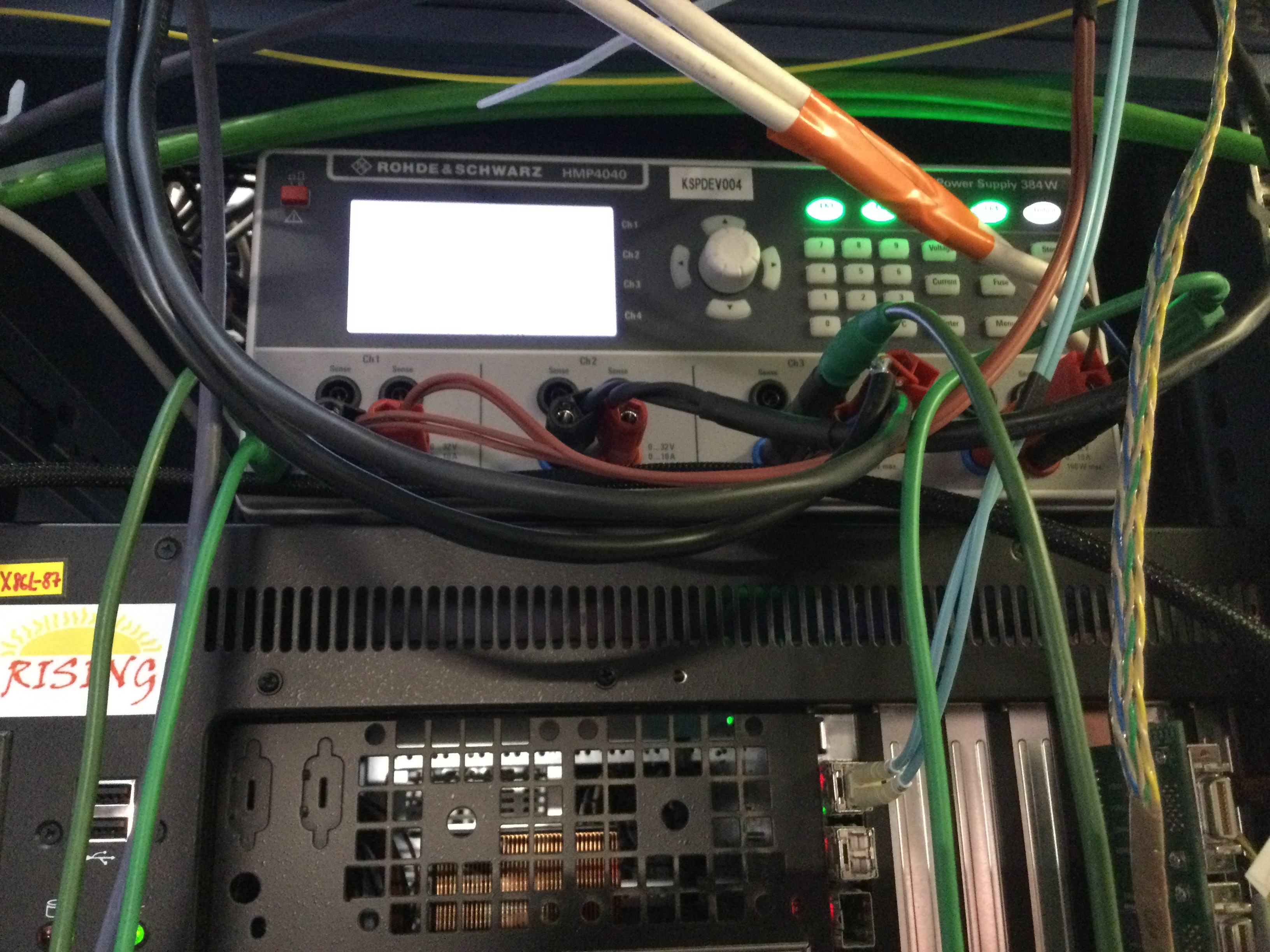
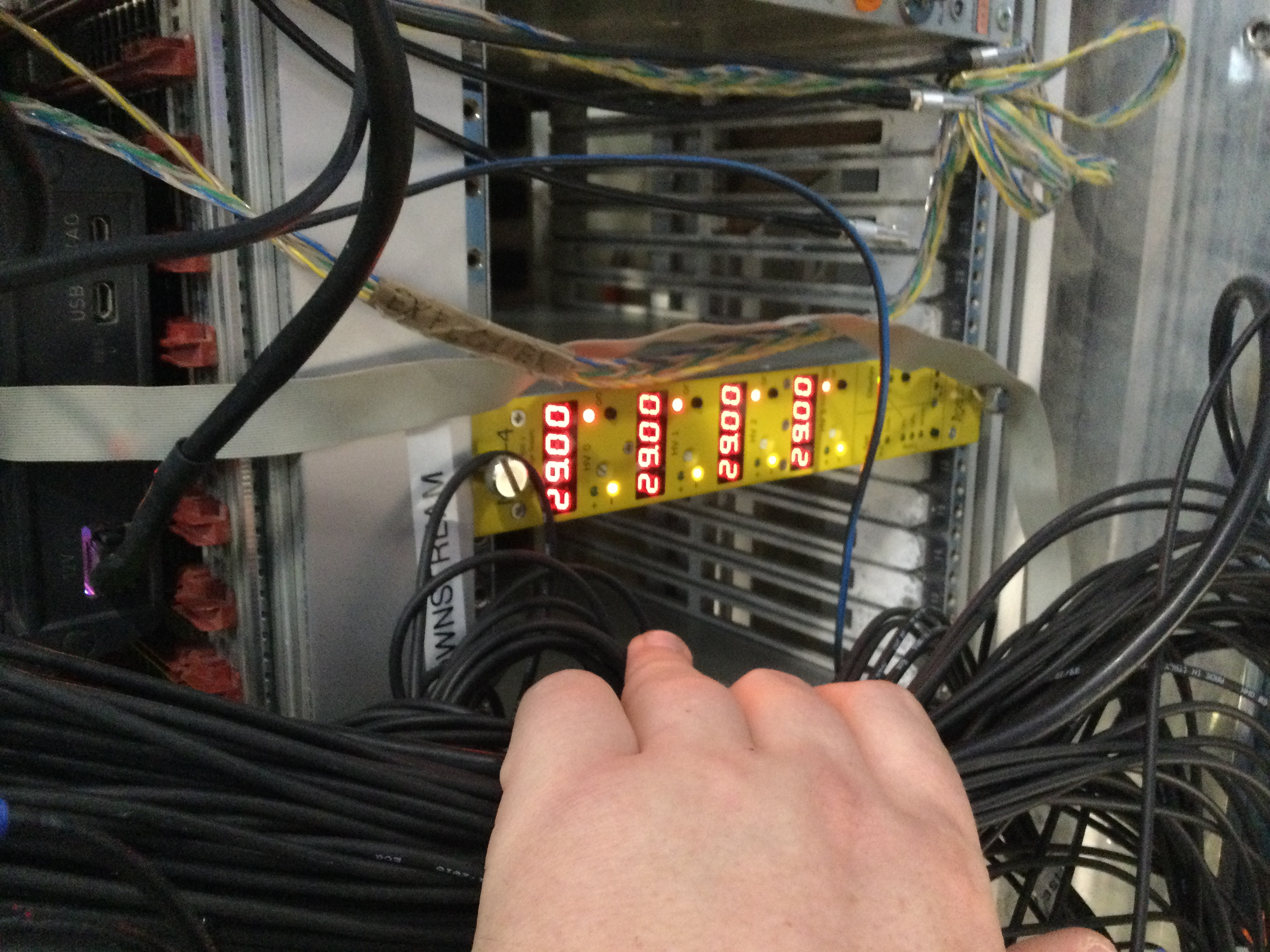
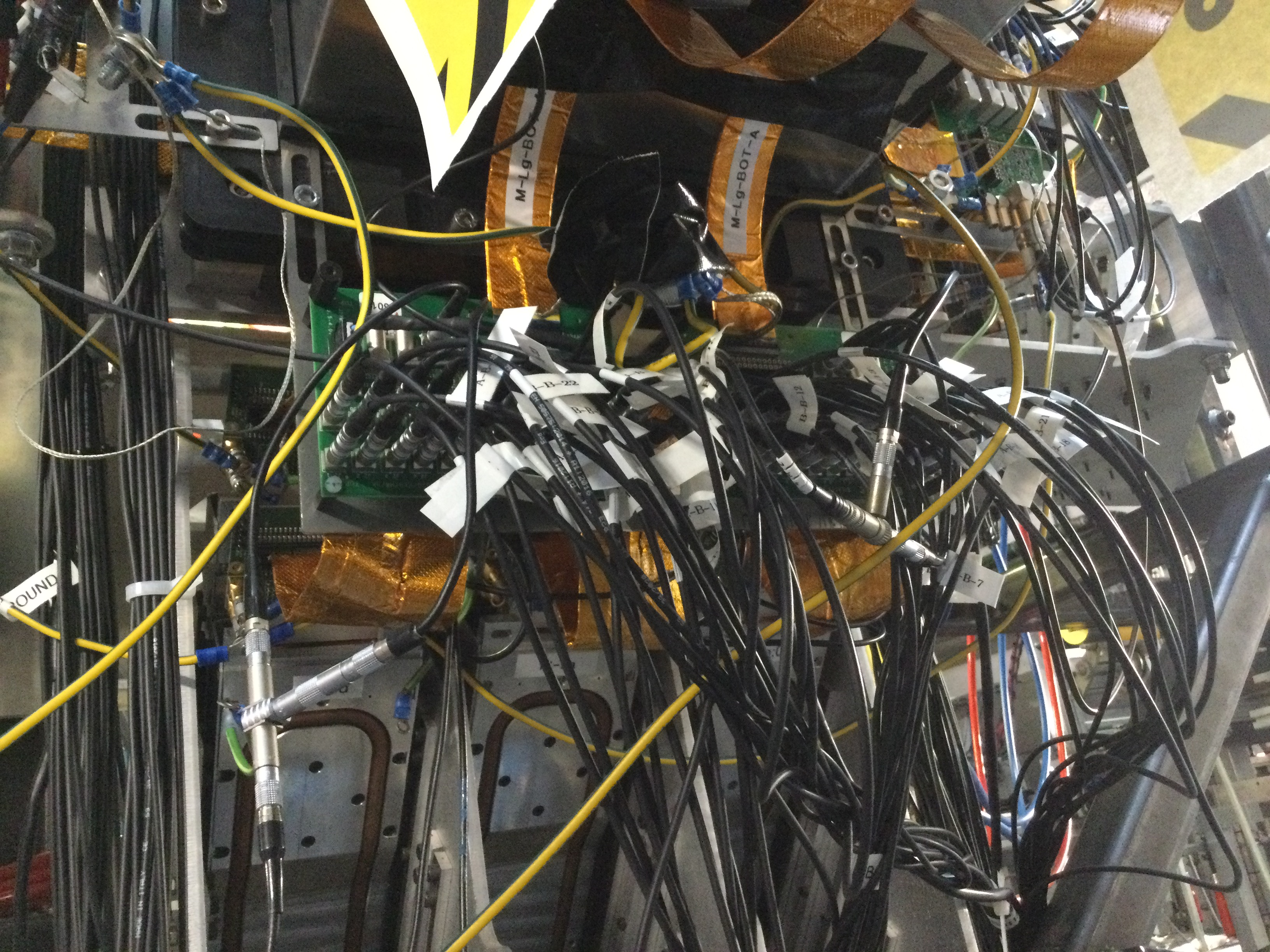
12.00 Photos of snout, bPlas driver PCBs, cabling, grounding and PSUs courtesy JB - attachments 18-27

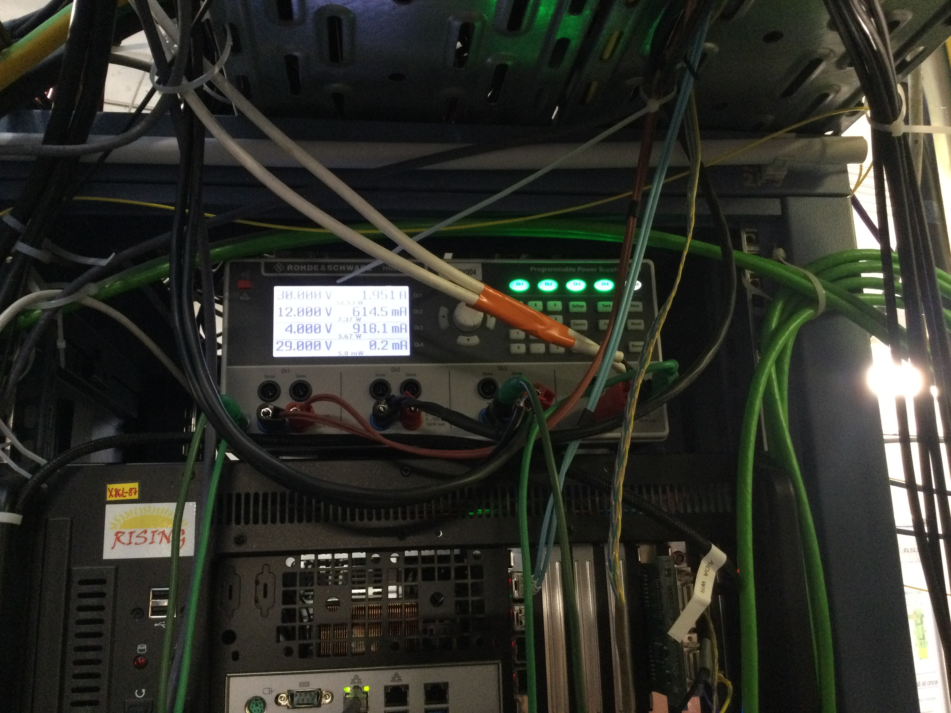
      N.B outputs of PN300 PSU at base of AIDA support stand are *not* ground ref'd - attachment 23


12.20 Slow comparator -> 0x64
      Pulser OFF
      All histograms zero'd

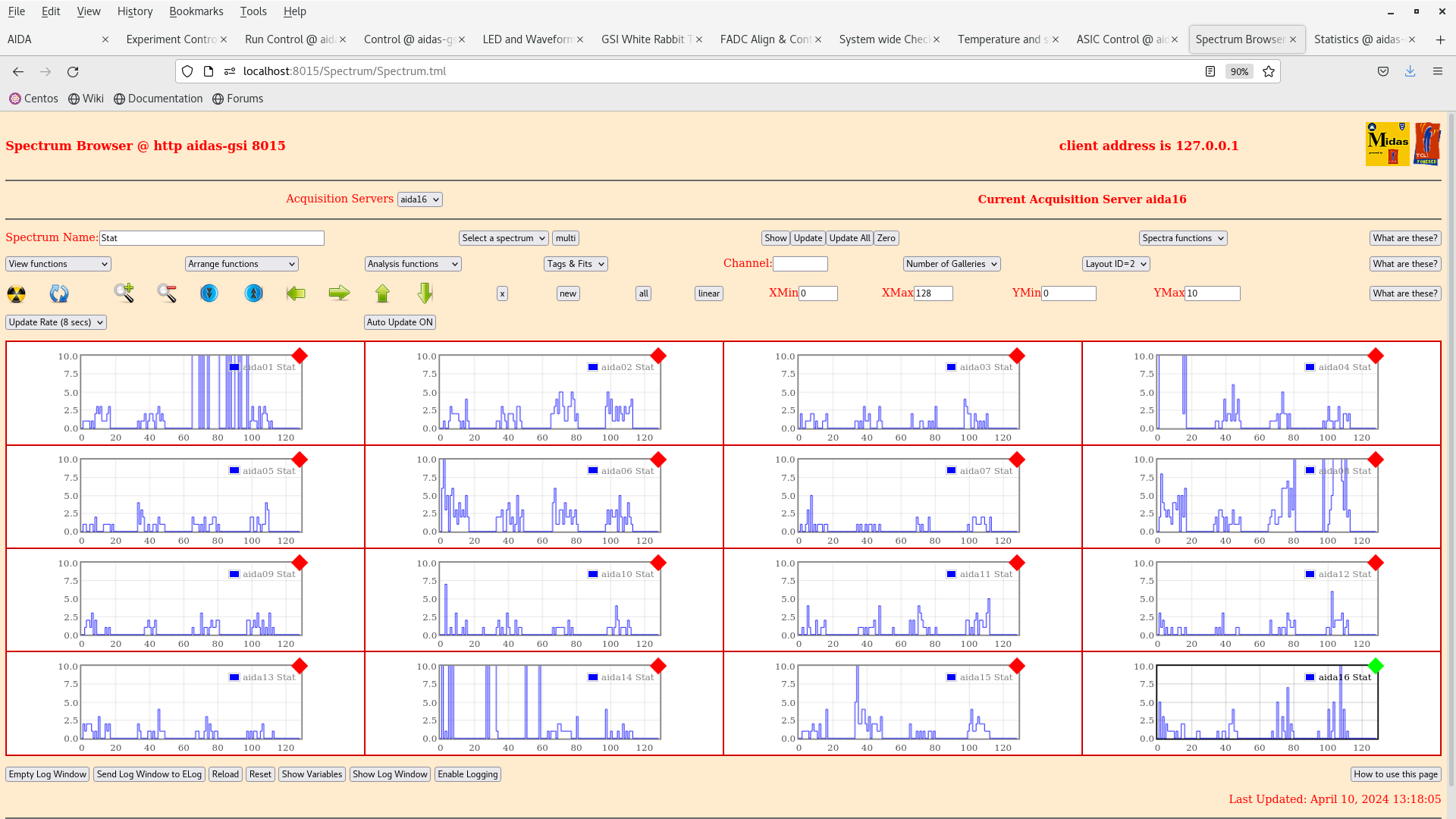
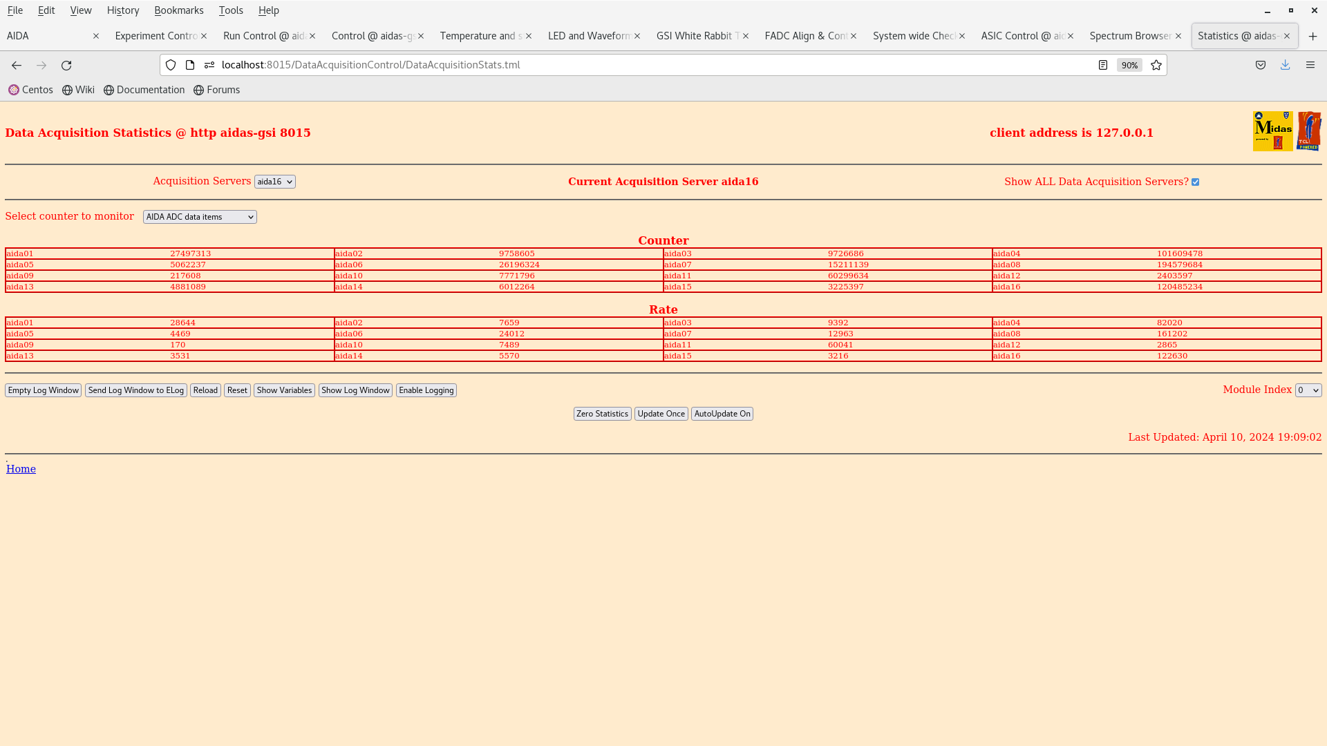
13.17 JB: returned from lunch. Current status of AIDA modules given by attachment 29.

15.55 While bPlast thresholds were being set the noise increased substantially.

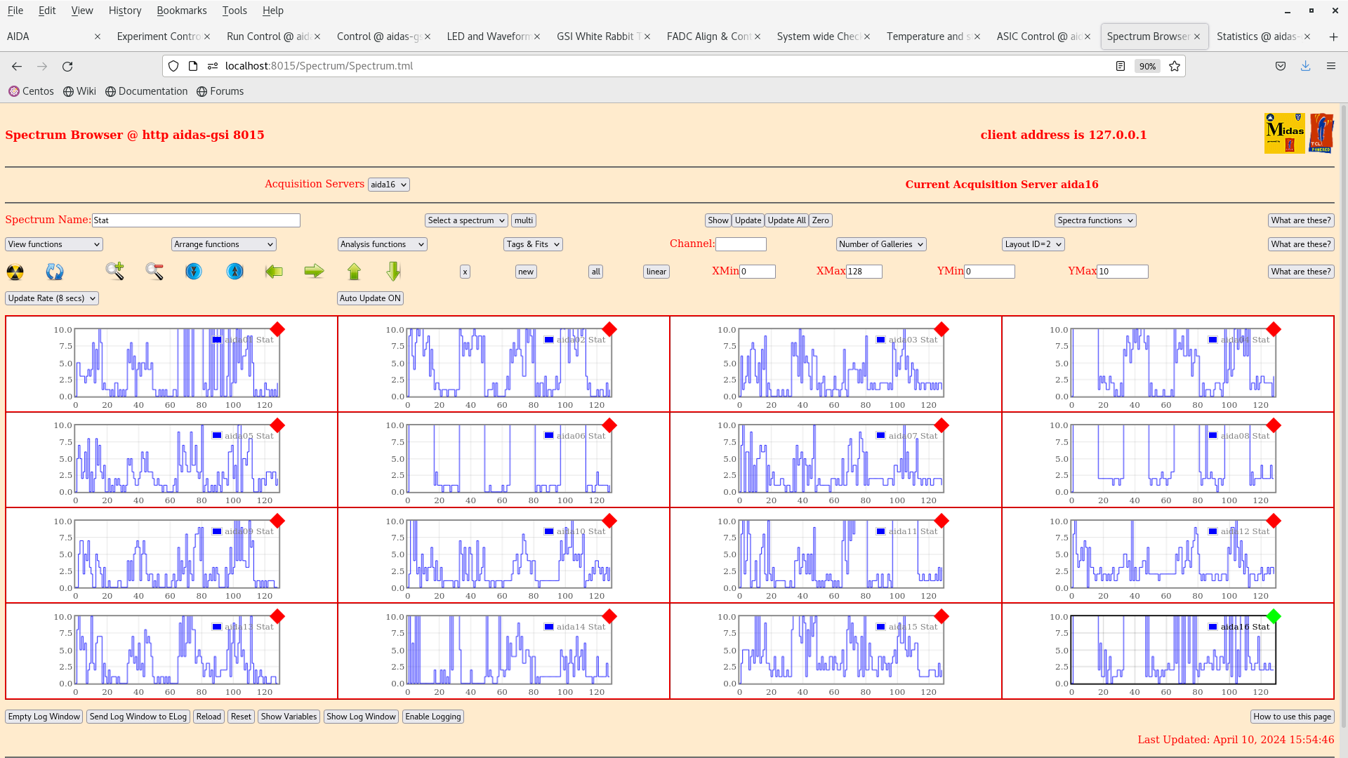
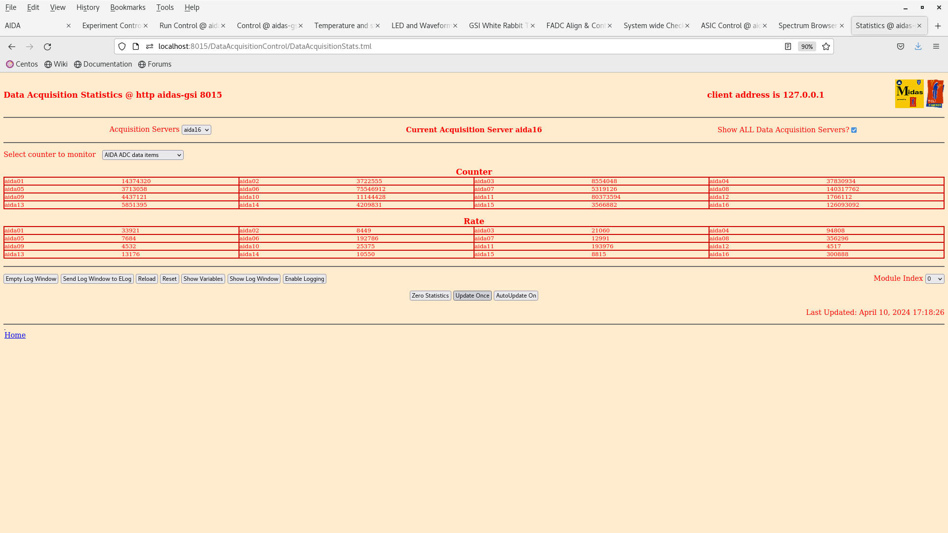
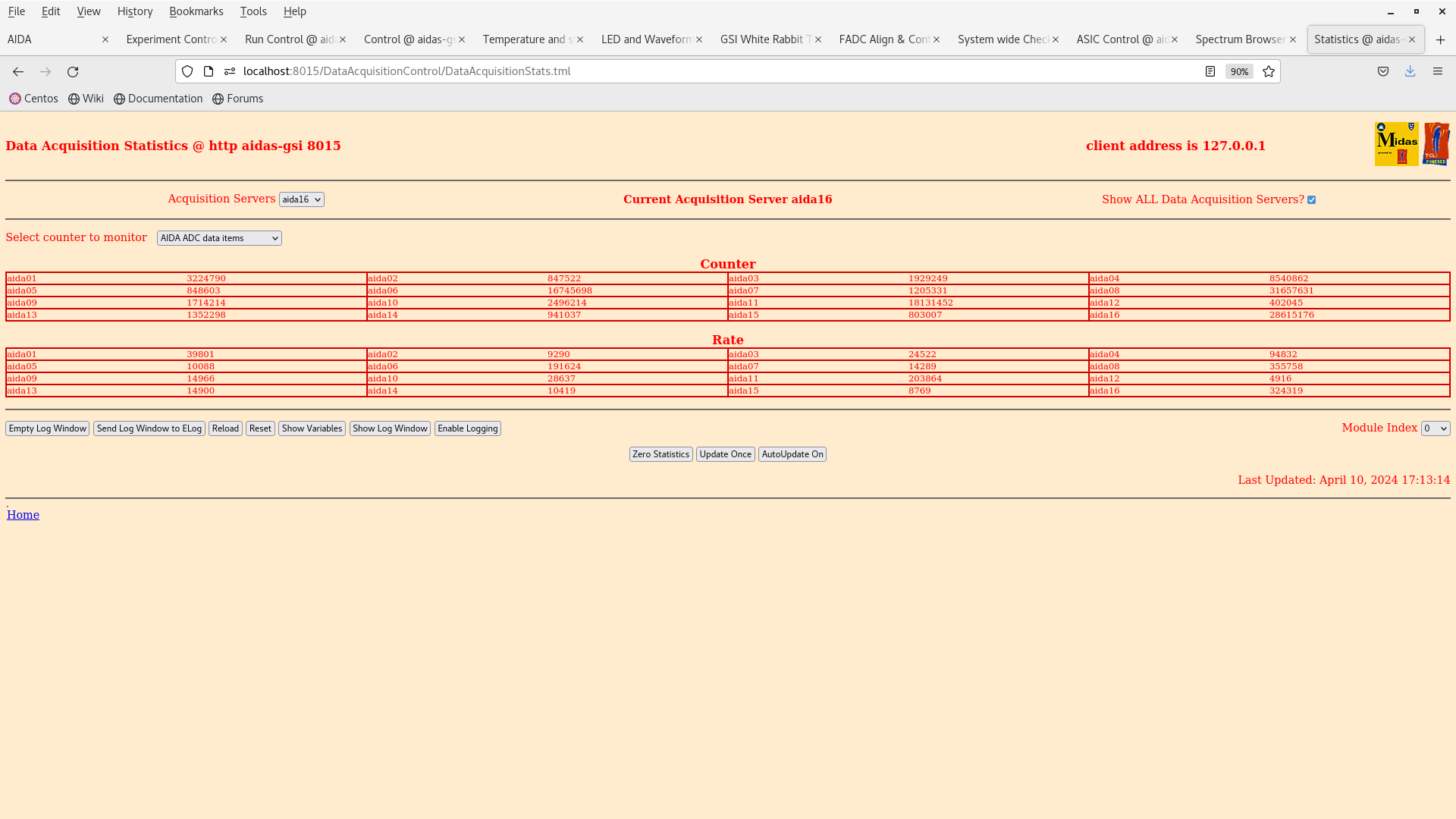
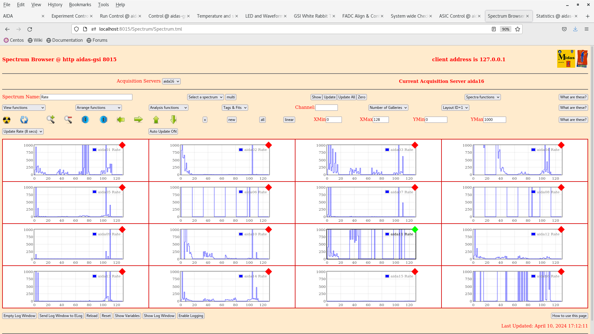
16.51 Replaced mezzanine of aida14, reinstalled and biasing detector. Resulting for noise conditions in the detector given by attachments 30-33.

17.31 With a multimeter it was found that there is continuity between the snout and the frame.

18.50 We tried to disconnect the cables of the short side of the bPlast detector and all of the grounds. This seemed to show an open line OL on the multimeter and whence connecting the bPlast grounds back excluding the short side ribbon cable grounds, the multimeter still read OL.
      We also tried to wedge paper between the short side ribbon cable of bPlast and the snout, but this did not work, the detector still reading continuity between the frame, booster board and snout.
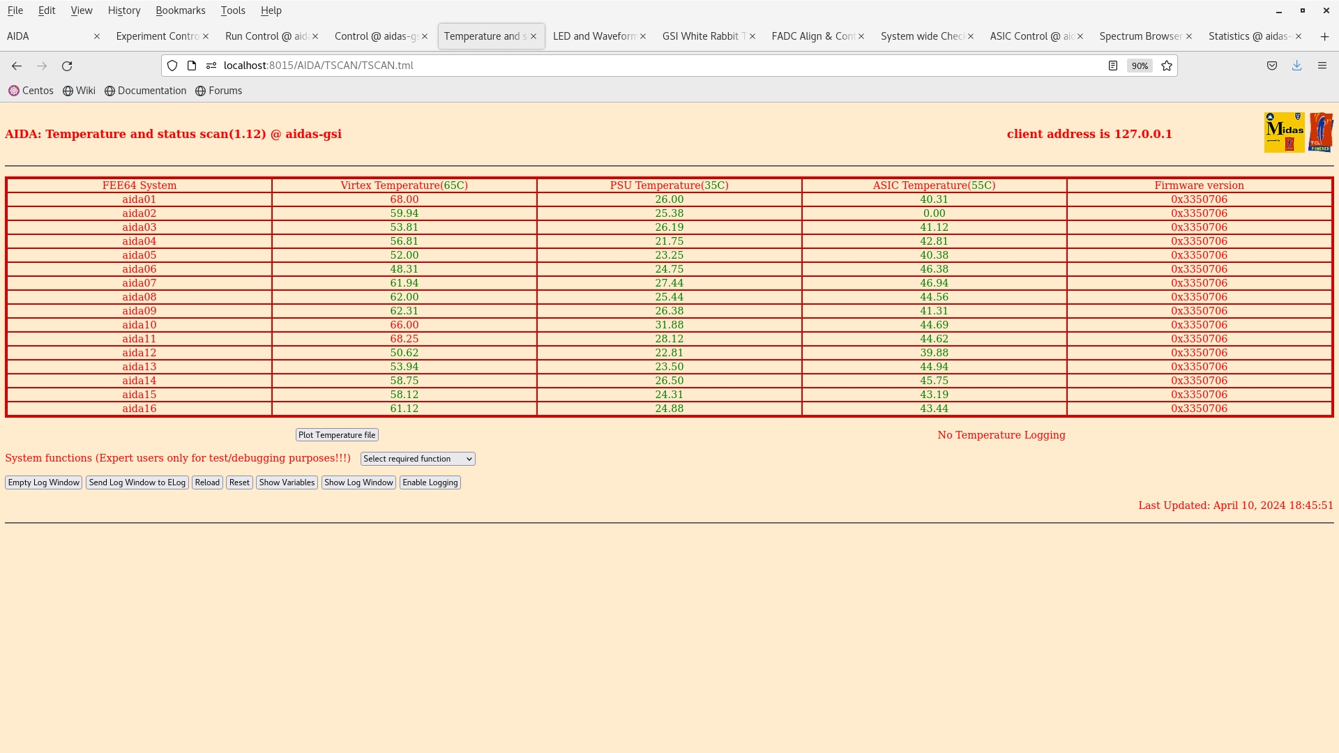
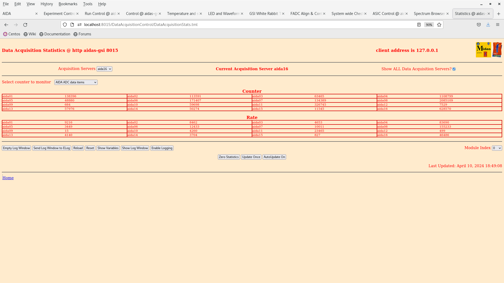
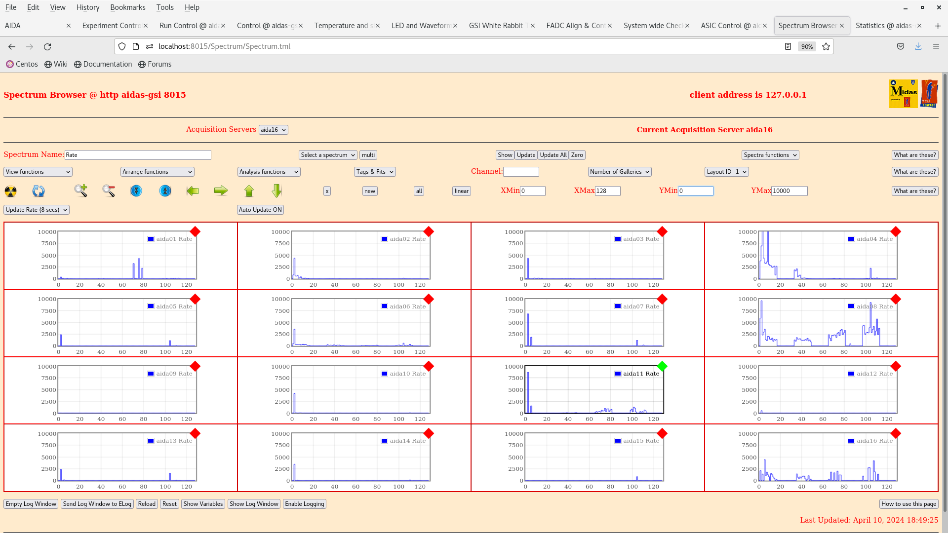
      The results after booting up the detector again are given by the attachments 34-36.
      The noise condition is appreciably better than before with 12 out of the 16 FEE64 modules with sub 20 kHz rates.
      Disconnect the BB7 preamp. ground from the frame.

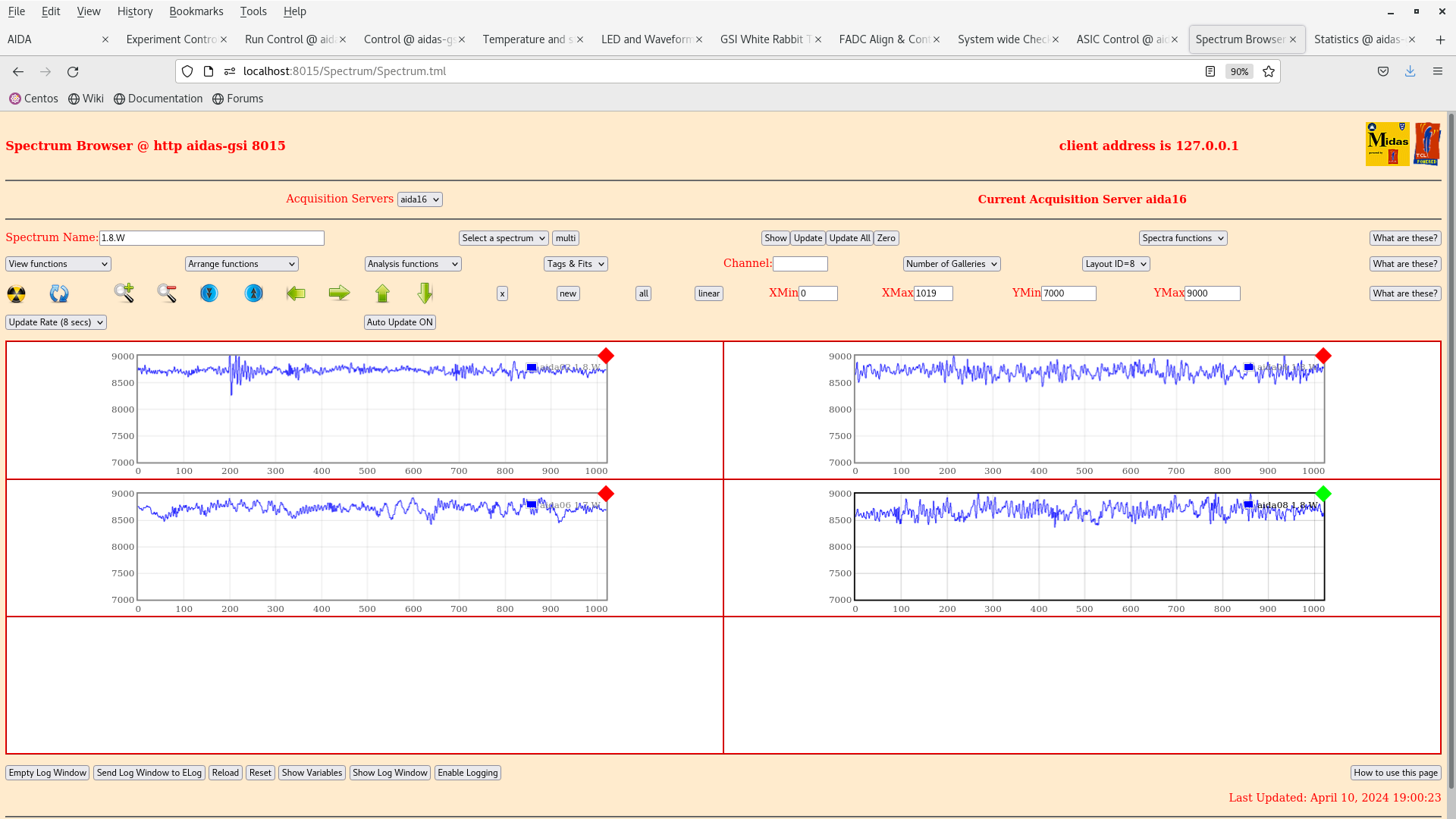
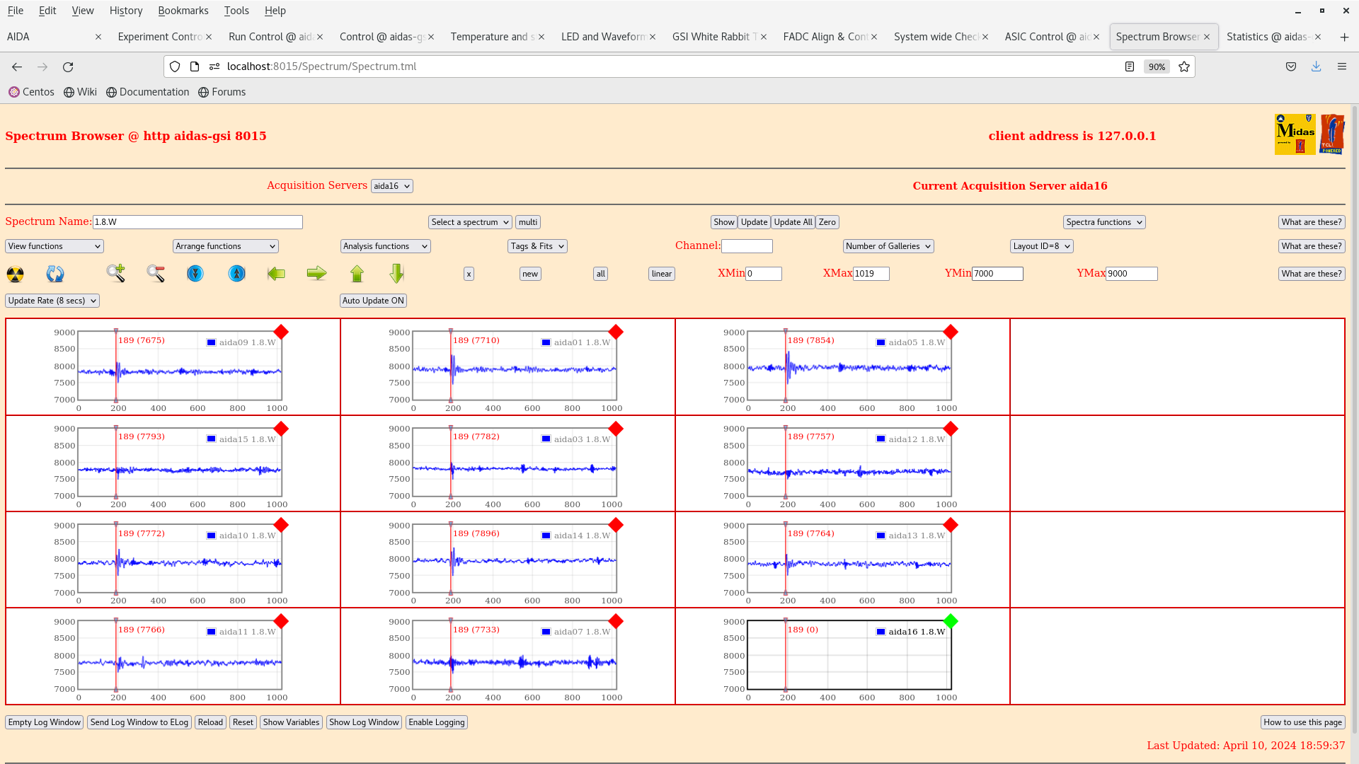
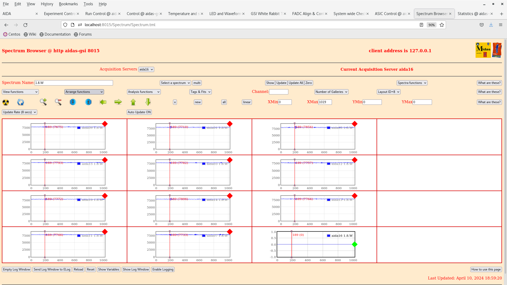
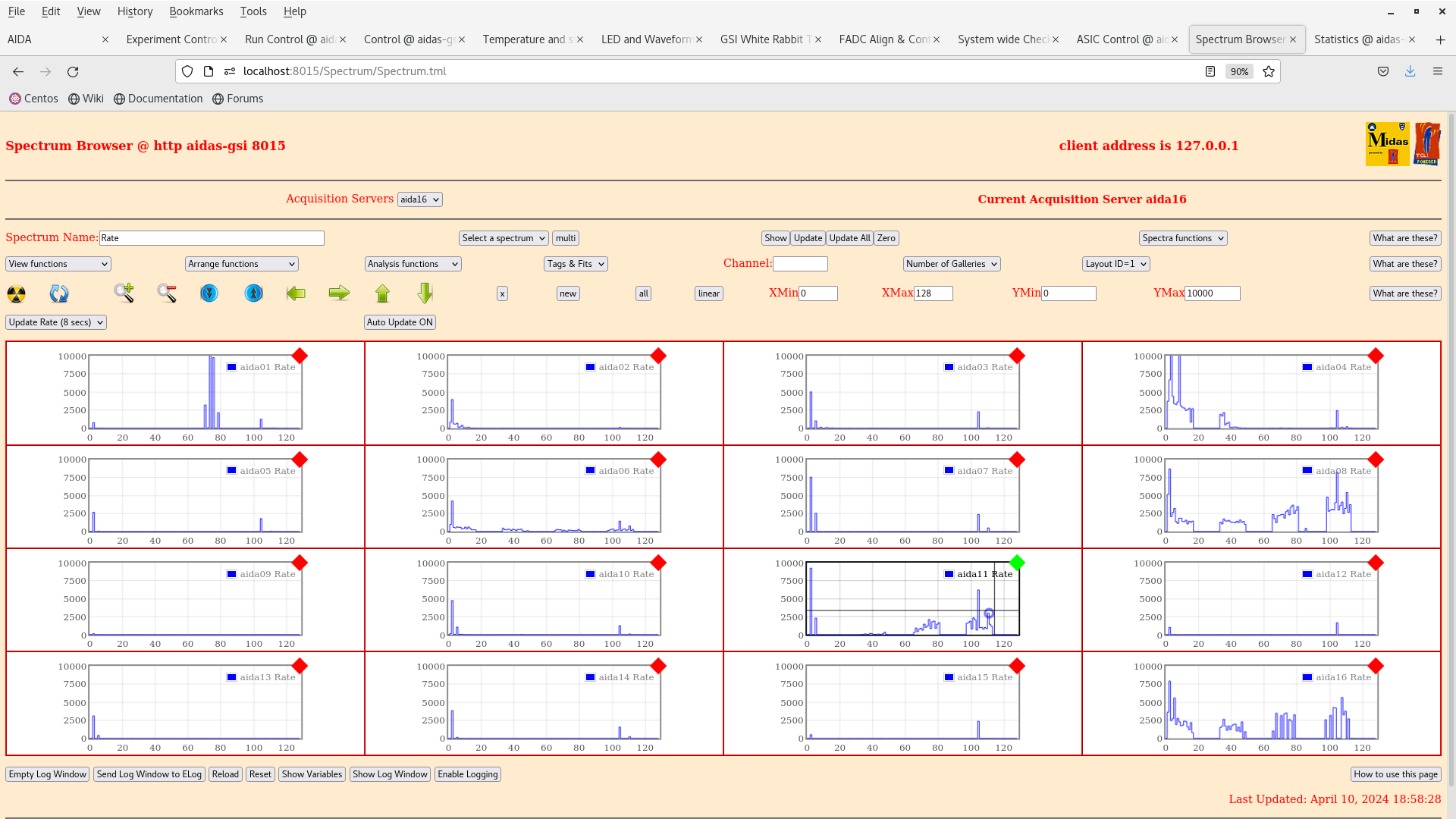
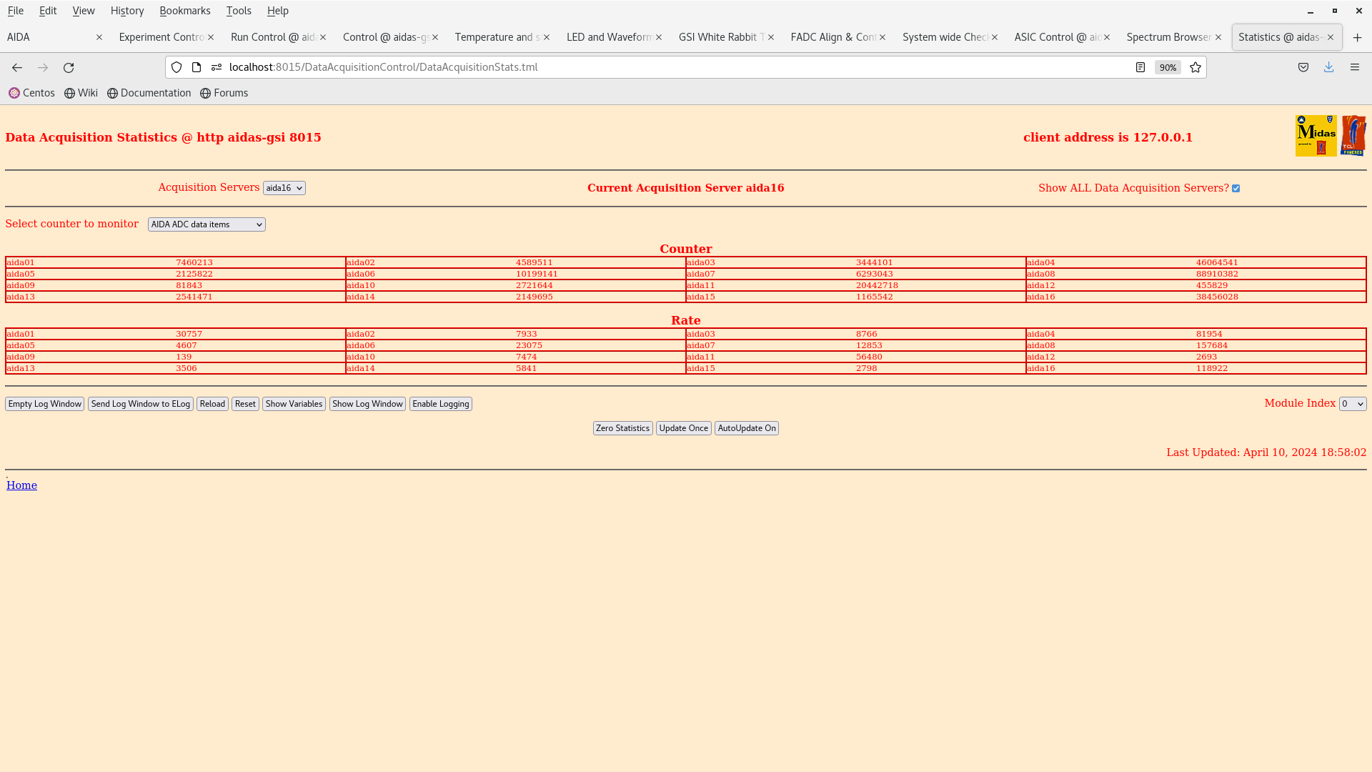
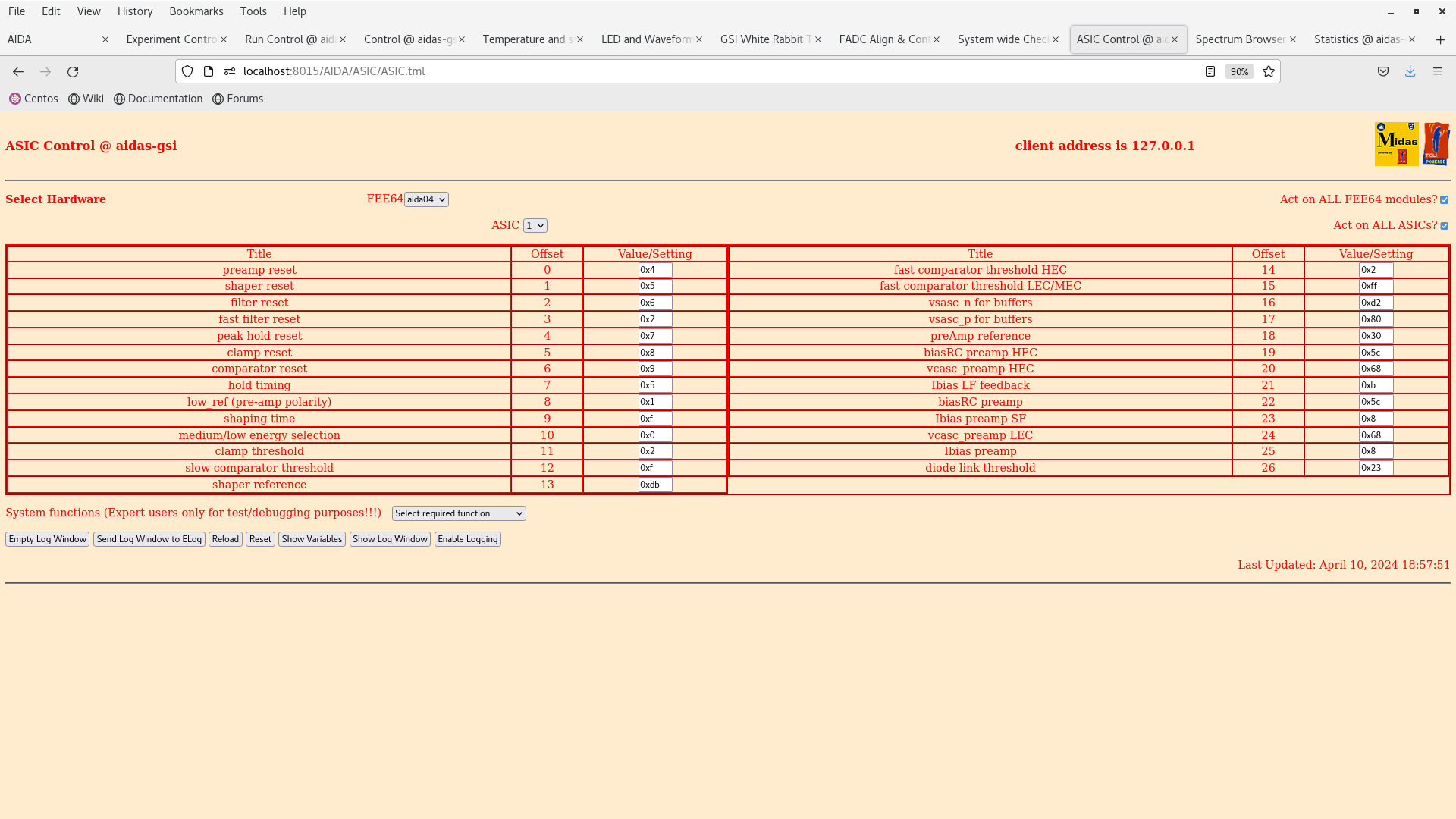
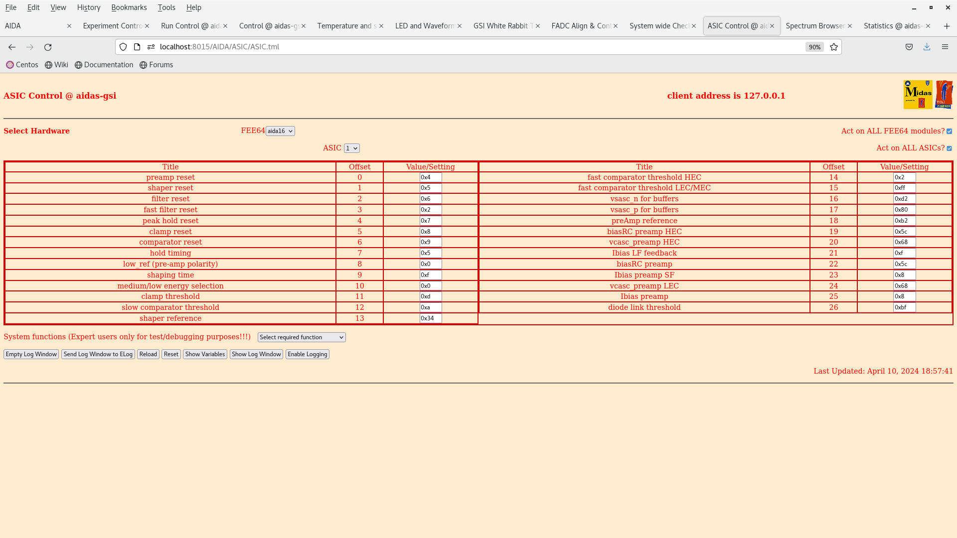
18.54 We powered up bPlast. The noise condition three FEEs got worse, aida01, aida11 and 06. The problem may be associated with downstream grounding. The results are given by the attachments 37-43. 10 out of the 16 FEE64 modules showed sub 20 kHz rates.

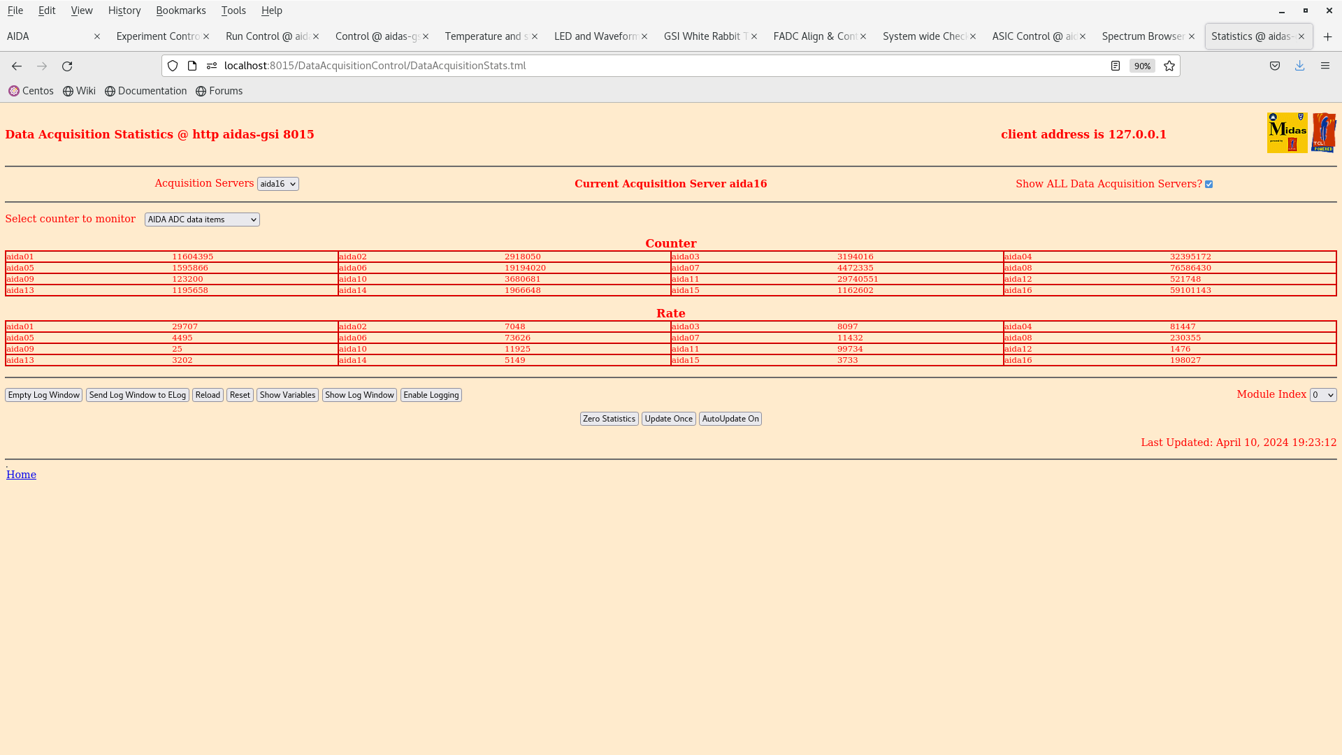
19.07 We turned off the power supply on the base of the snout support. PN300 Attachment 23. Rates did not change - attachment 44.

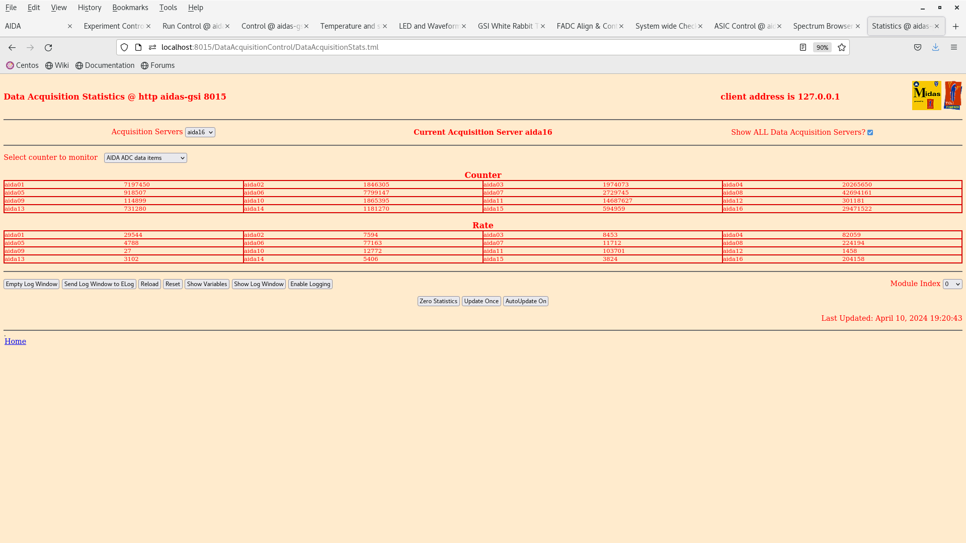
19.10 We turned off the mesytec PSU that is located in the bPlast NIM crate. No change was observed in the rates - attachment 45.

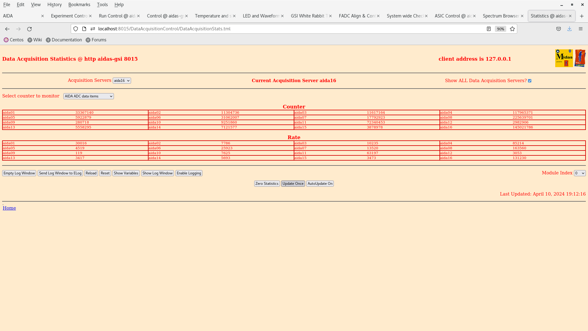
19.13 We turned off the R&SRMP4040 PSU that is located above the AIDA crate. And the noise situation did not change attachment 46.

19.22 Leaving the R&SRMP4040 PSU off we turned back on the mesytec PSU and PN300 PSU, attachment 47.

Summary:

It is clear that with no continuity on the short side we are able to reduce the noise back to the scenario where bPlast was not connected. However, powering bPlast introduced substantial noise in both DSSSDs that did not go away when turning all the PSUs off. There might be some hysteresis in the system (this is just speculation).

The situation is still fair considering that 10 out of the 16 FEE64 modules are in the sub 20 kHz rate level (good noise condition).

TO-DO for 11.04.2024

- Try bringing bPlast ground back to the PSU ground.

- Recheck the downstream detector bias and ground scheme.
|
| Attachment 1: Screenshot_from_2024-04-10_09-43-13.png
|
|
| Attachment 2: Screenshot_from_2024-04-10_09-46-53.png
|
|
| Attachment 3: Screenshot_from_2024-04-10_09-49-03.png
|
|
| Attachment 4: Screenshot_from_2024-04-10_09-49-35.png
|
|
| Attachment 5: Screenshot_from_2024-04-10_09-50-23.png
|
|
| Attachment 6: Screenshot_from_2024-04-10_09-50-52.png
|
|
| Attachment 7: Screenshot_from_2024-04-10_09-50-42.png
|
|
| Attachment 8: Screenshot_from_2024-04-10_09-53-41.png
|
|
| Attachment 9: Screenshot_from_2024-04-10_09-53-17.png
|
|
| Attachment 10: Screenshot_from_2024-04-10_09-52-49.png
|
|
| Attachment 11: Screenshot_from_2024-04-10_09-52-22.png
|
|
| Attachment 12: Screenshot_from_2024-04-10_09-59-02.png
|
|
| Attachment 13: Screenshot_from_2024-04-10_10-51-20.png
|
|
| Attachment 14: Screenshot_from_2024-04-10_10-50-37.png
|
|
| Attachment 15: Screenshot_from_2024-04-10_10-52-40.png
|
|
| Attachment 16: Screenshot_from_2024-04-10_10-52-16.png
|
|
| Attachment 17: Screenshot_from_2024-04-10_11-41-42.png
|
|
| Attachment 18: IMG_0010.JPG
|
|
| Attachment 19: IMG_0007.JPG
|
|
| Attachment 20: IMG_0012.JPG
|
|
| Attachment 21: IMG_0005.JPG
|
|
| Attachment 22: IMG_0009.JPG
|
|
| Attachment 23: IMG_0015.JPG
|
|
| Attachment 24: IMG_0014.JPG
|
|
| Attachment 25: IMG_0017.JPG
|
|
| Attachment 26: IMG_0006.JPG
|
|
| Attachment 27: IMG_0013.JPG
|
|
| Attachment 28: Screenshot_from_2024-04-10_13-18-09.png
|
|
| Attachment 29: Screenshot_from_2024-04-10_15-55-15.png
|
|
| Attachment 30: Screenshot_from_2024-04-10_17-19-01.png
|
|
| Attachment 31: Screenshot_from_2024-04-10_17-13-25.png
|
|
| Attachment 32: Screenshot_from_2024-04-10_17-12-33.png
|
|
| Attachment 33: Screenshot_from_2024-04-10_17-04-11.png
|
|
| Attachment 34: Screenshot_from_2024-04-10_18-49-54.png
|
|
| Attachment 35: Screenshot_from_2024-04-10_18-49-50.png
|
|
| Attachment 36: Screenshot_from_2024-04-10_18-49-44.png
|
|
| Attachment 37: Screenshot_from_2024-04-10_19-00-27.png
|
|
| Attachment 38: Screenshot_from_2024-04-10_18-59-41.png
|
|
| Attachment 39: Screenshot_from_2024-04-10_18-59-26.png
|
|
| Attachment 40: Screenshot_from_2024-04-10_18-58-43.png
|
|
| Attachment 41: Screenshot_from_2024-04-10_18-58-21.png
|
|
| Attachment 42: Screenshot_from_2024-04-10_18-57-53.png
|
|
| Attachment 43: Screenshot_from_2024-04-10_18-57-46.png
|
|
| Attachment 44: Screenshot_from_2024-04-10_19-23-16.png
|
|
| Attachment 45: Screenshot_from_2024-04-10_19-20-55.png
|
|
| Attachment 46: Screenshot_from_2024-04-10_19-12-22.png
|
|
| Attachment 47: Screenshot_from_2024-04-10_19-09-07.png
|
|
|
580
|
Fri Apr 19 13:52:34 2024 |
JB, CC, TD | Friday 19 April contd. |
12.00 Replaced AIDA ASIC mezzanine of aida01 to fix issue with asic #3

      During replacement the HDMI connector of the adjacent FEE64 aida09 became disconnected from the FEE64 PCB
      aida09 ( MAC ee:10 ) replaced (MAC 41:cf:ad )

      AIDA FEE64 adaptor PCBs for aida01, aida14 and aida09 disconnected and re-connected during this process

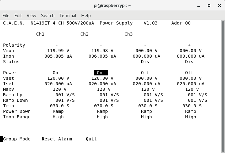
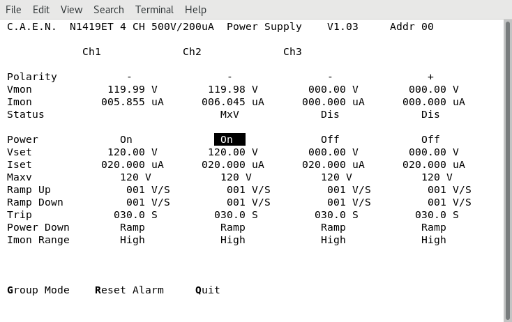
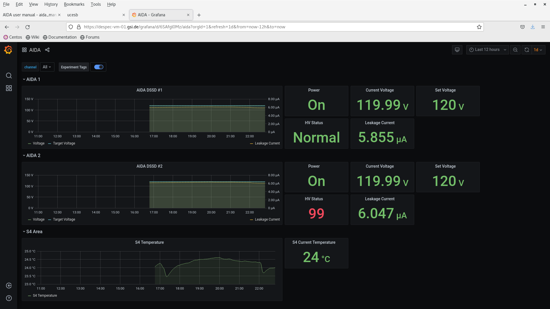
      DSSSD bias & leakage current OK - attachment 1

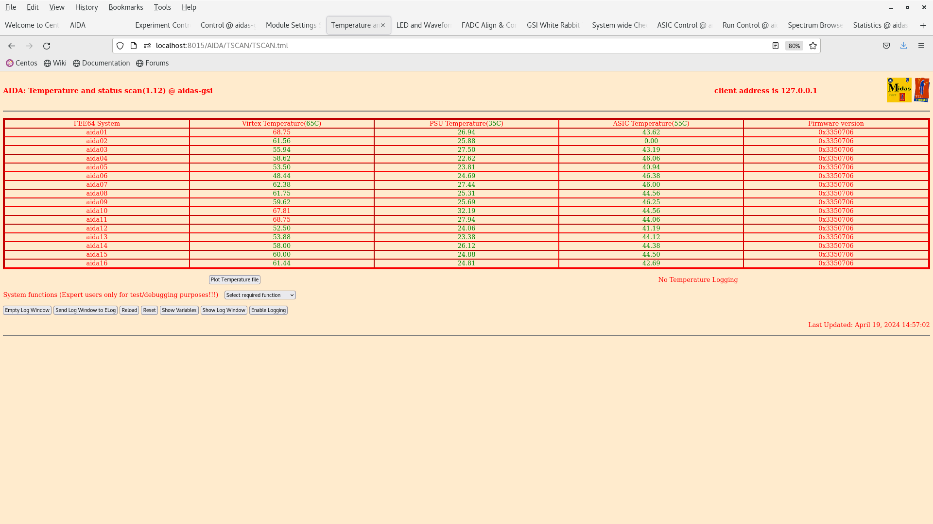
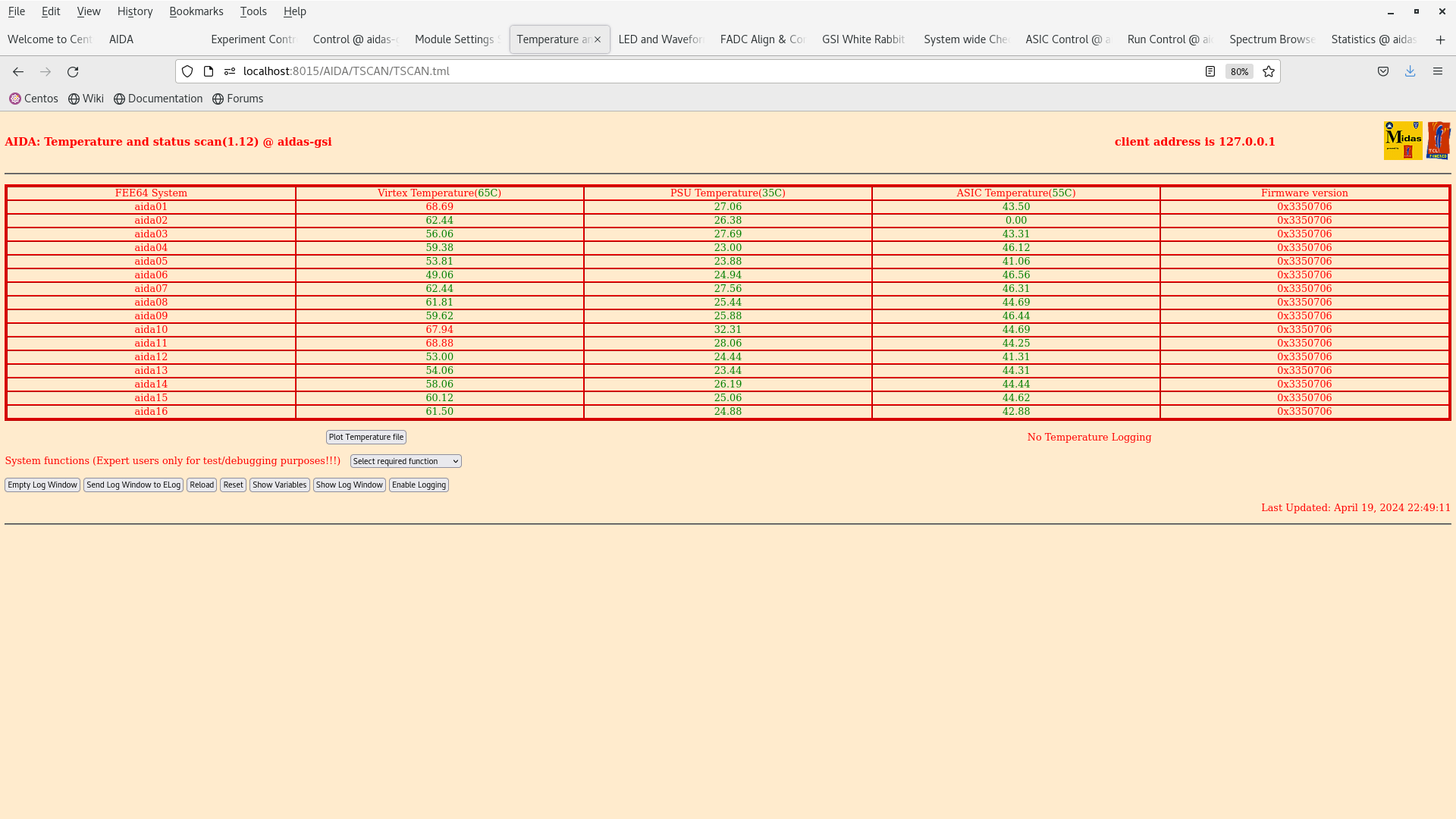
      FEE64 temps OK - attachment 2
       *except* aida02 ASIC temp - known fault

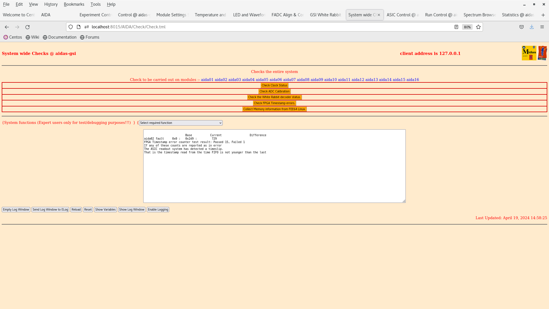
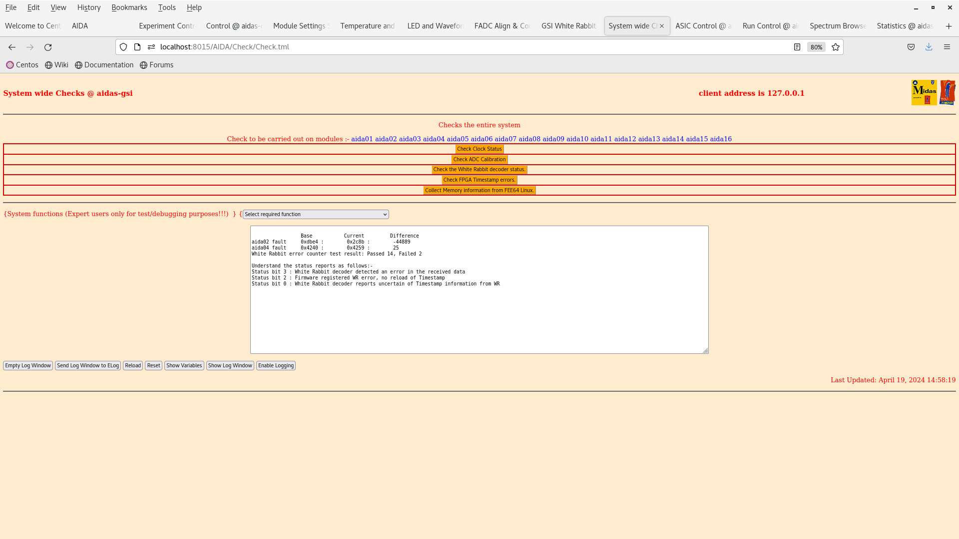
      System wide checks OK *except* WR/FPGA errors - attachments 3-4

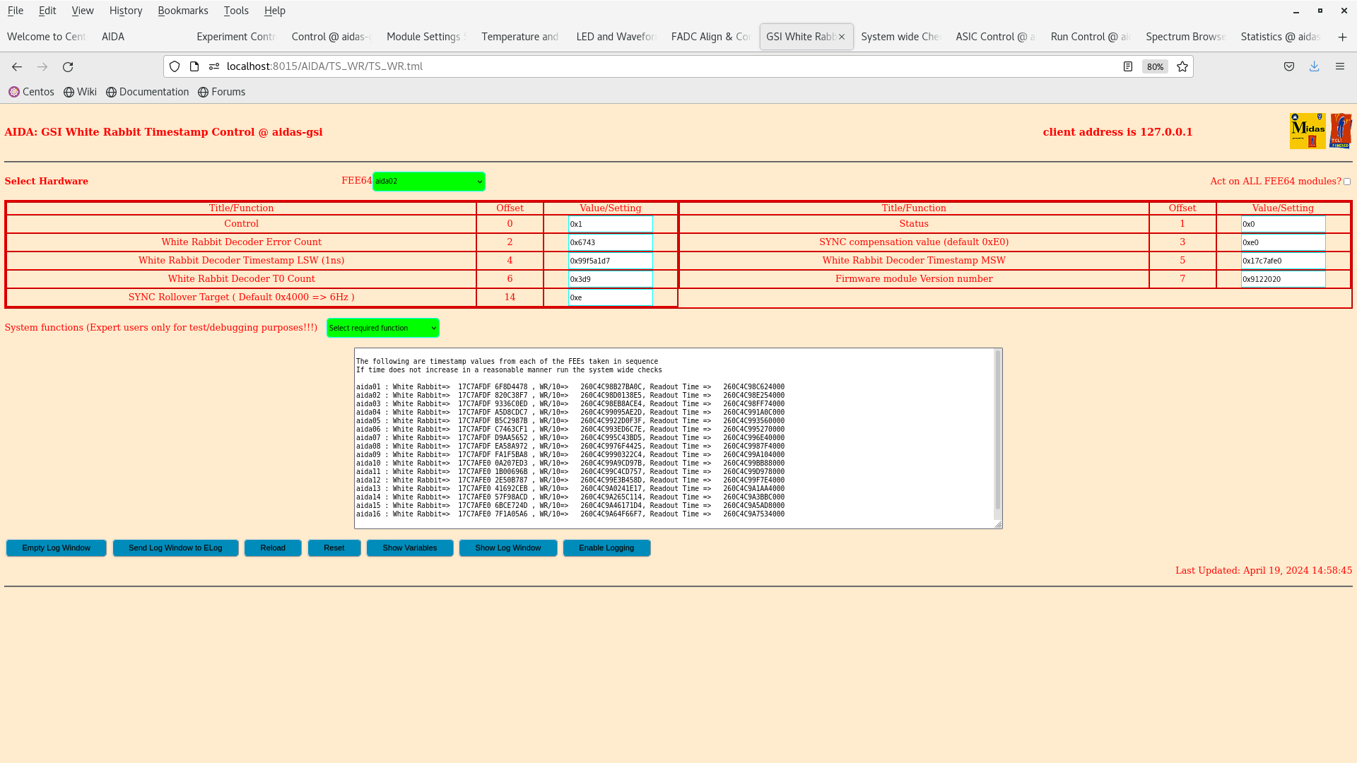
      WR timestamps OK - attachment 5

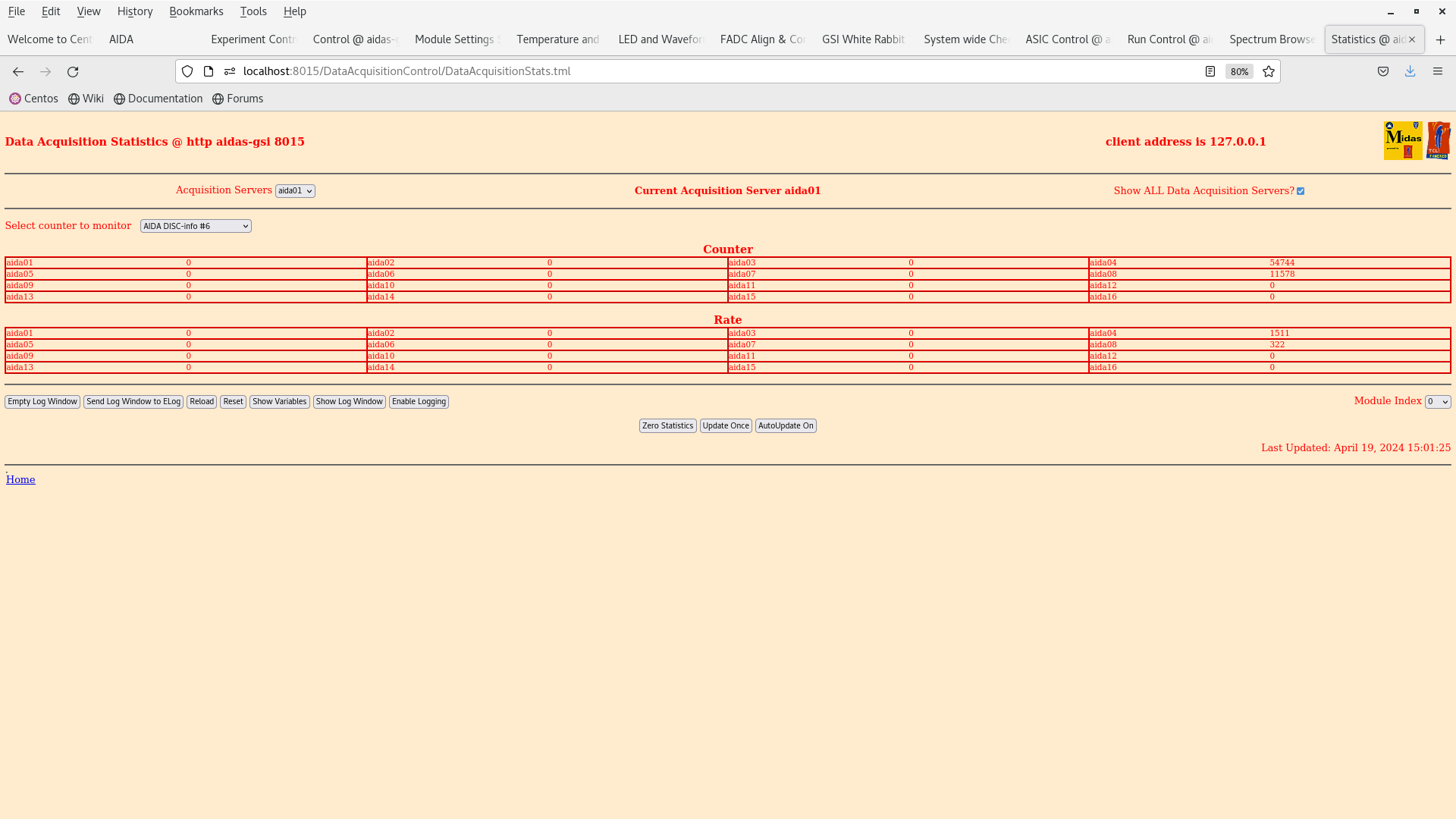
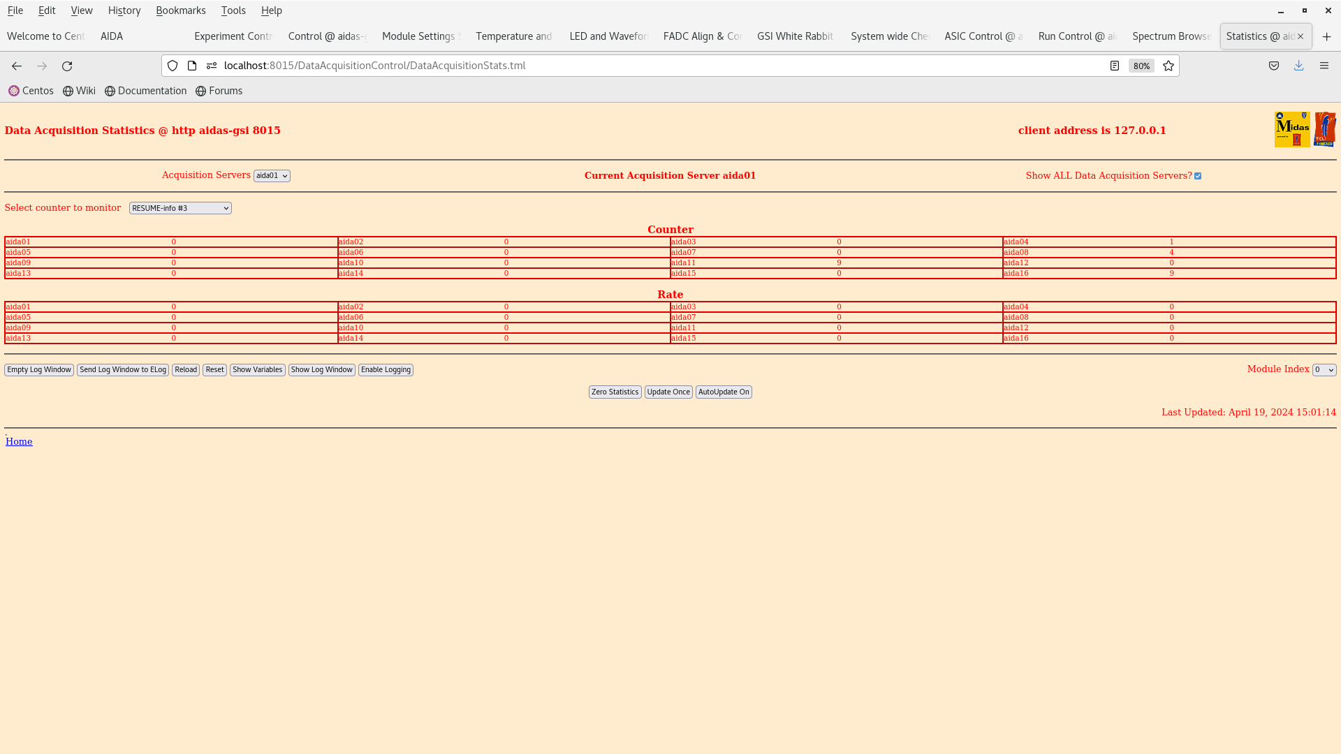
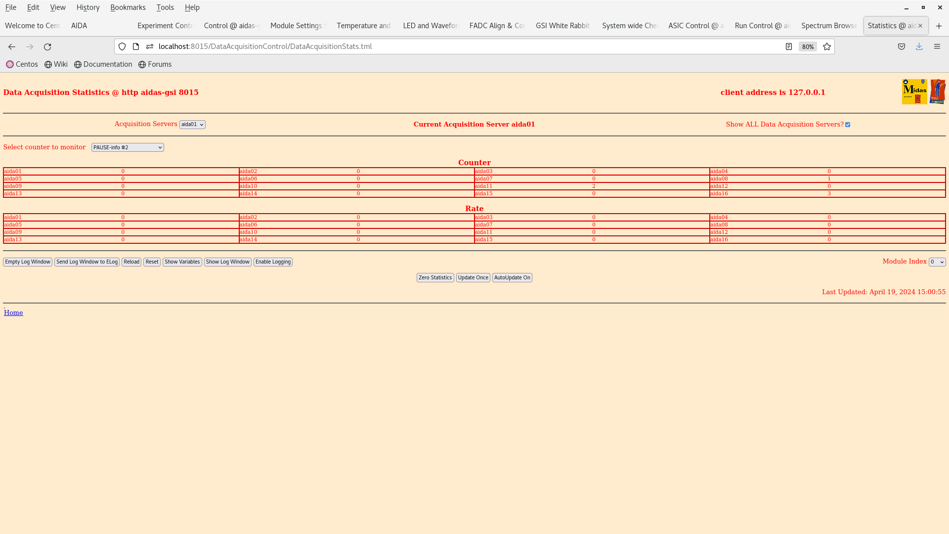
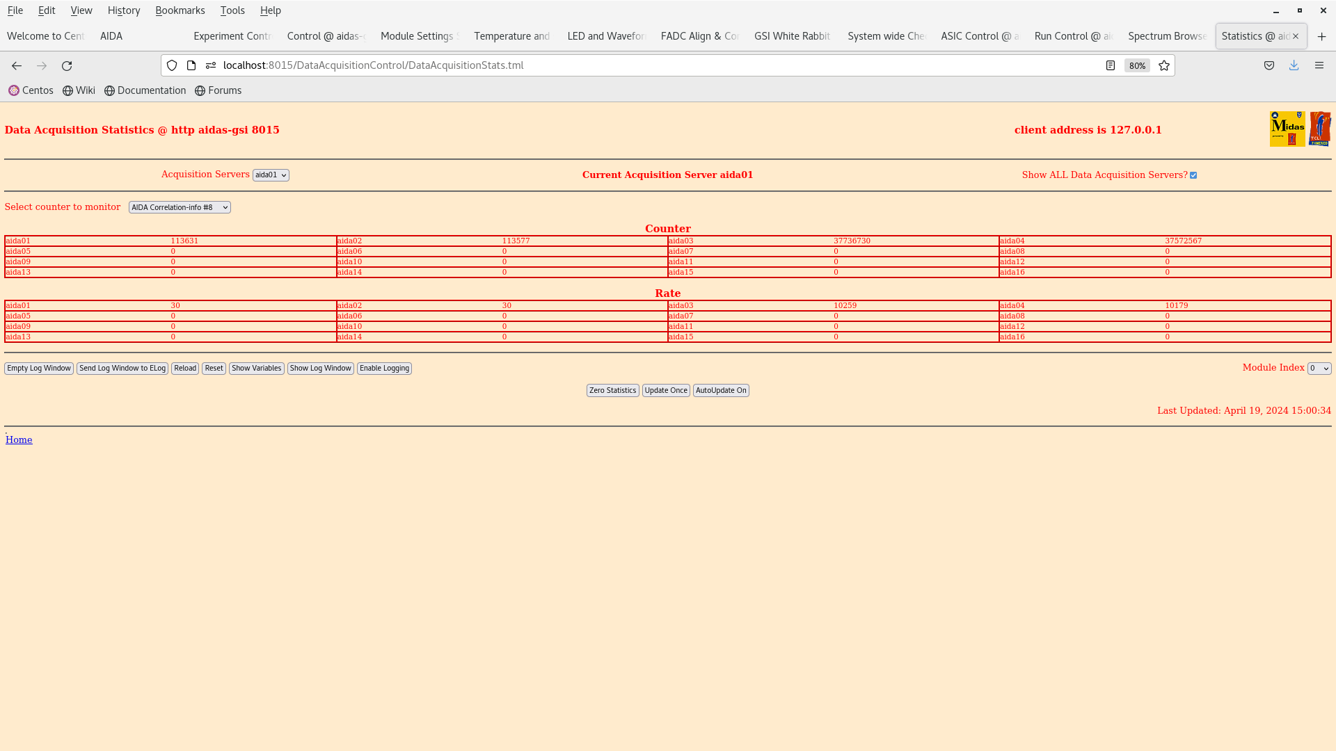
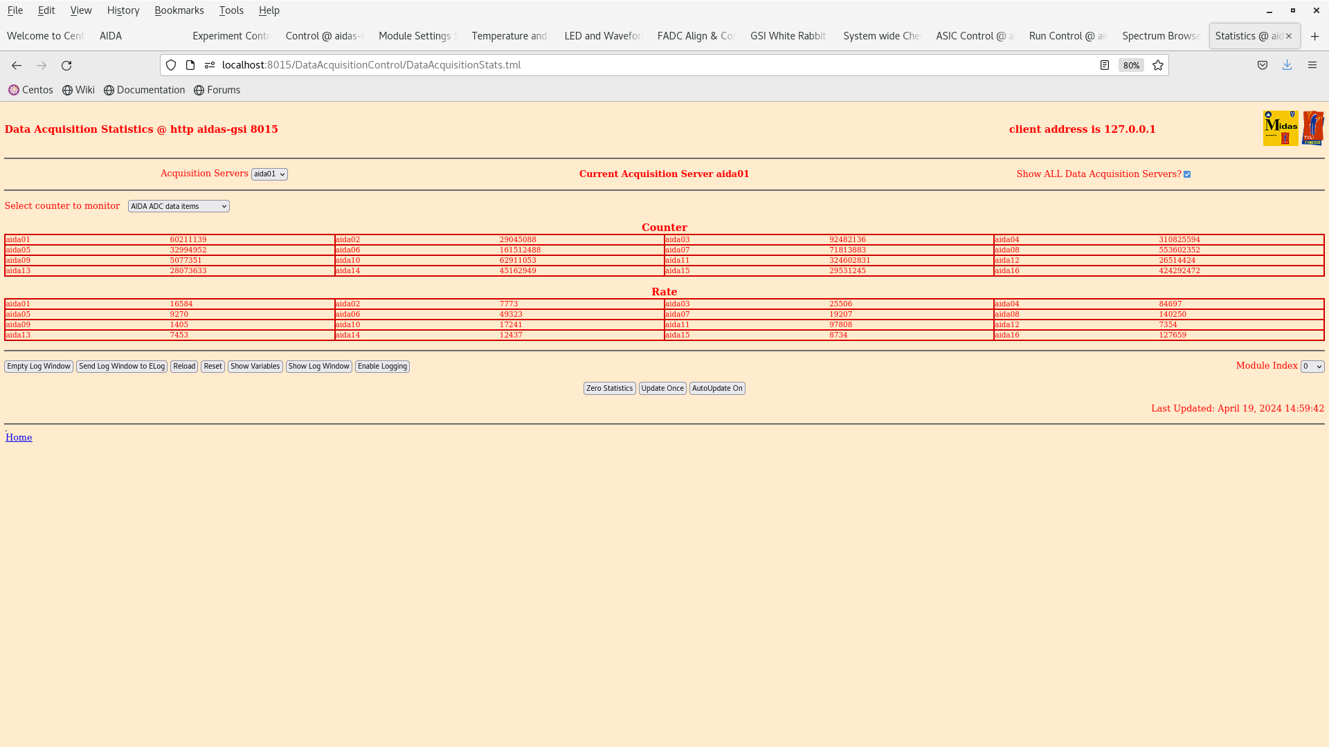
      ADC, DISC, PAUSE, RESUME and correlation data stats - attachments 6-10
       ADC data items 10/16 < 20k, max 143k

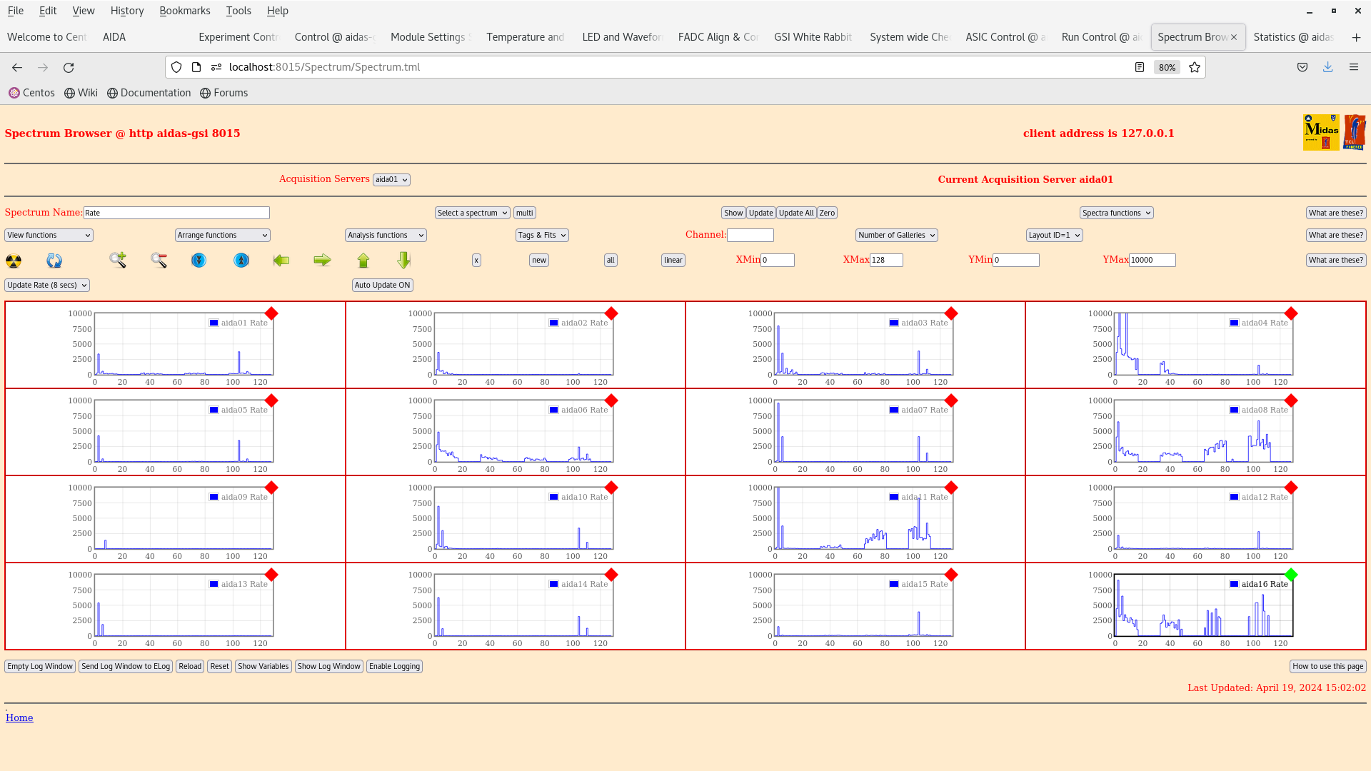
      per FEE64 Rate spectra - attachment 11

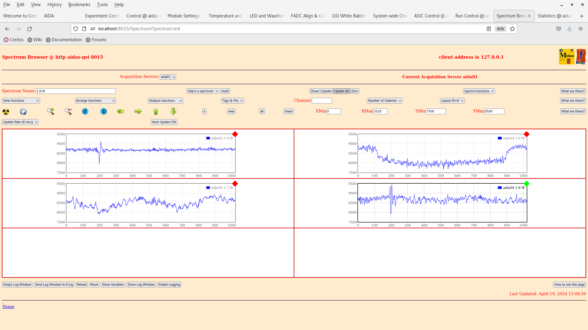
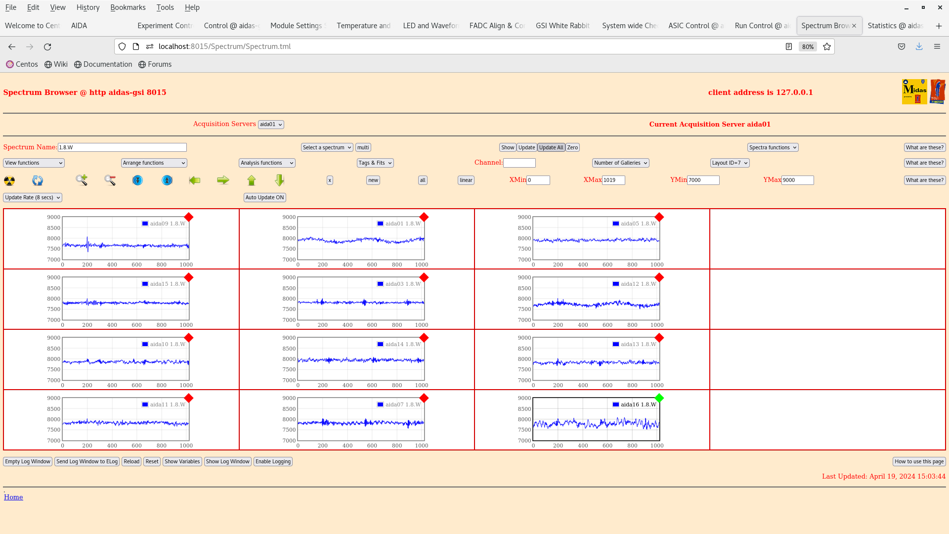
      per FEE64 1.8.W spectra - 20us FSR - attachments 12-13


15.10 Synchronise ASIC clocks
      Re-calibrate ALL ADCs

      ASIC settings 2024Mar27-11.25.32

      Changes ( https://elog.ph.ed.ac.uk/CARME/499 )

       IBias LF feedback from 0xf to 0x8
       Diode link threshold from 0xbf to 0xca

      New ASIC settings saved as 2024Apr19-15.22.49

      All FEE64 slow comparators -> 0x14

      Data file S100_alpha/R12

      Pulser ealkthrough (test +)

      BNC PB-5 settings

      Amplitude 10.0-1.0V @ 1.0V step
      Attenuation x10
      Frequency 25Hz
      Polarity +
      Tail pulse
      tau_d 1ms

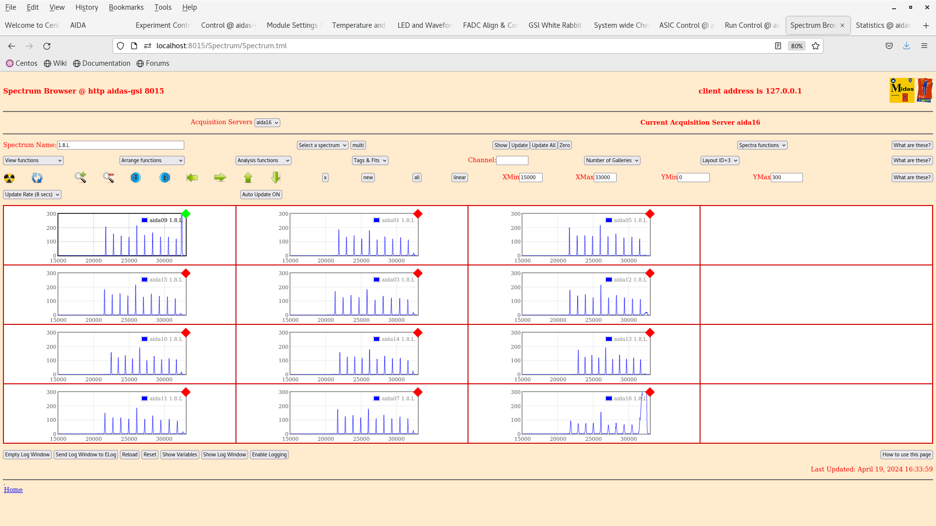
16.35 DAQ ends OK file S100_alpha/R12_24

      per p+n FEE64 1.8.L spectra - attachment 14
       aida09 pulser peak width 54 ch FWHM

17.38 Data file S100_alpha/R13

      Pulser walkthrough (test -)

      BNC PB-5 settings

      Amplitude 10.0-1.0V @ 1.0V step
      Attenuation x10
      Frequency 25Hz
      Polarity -
      Tail pulse
      tau_d 1ms

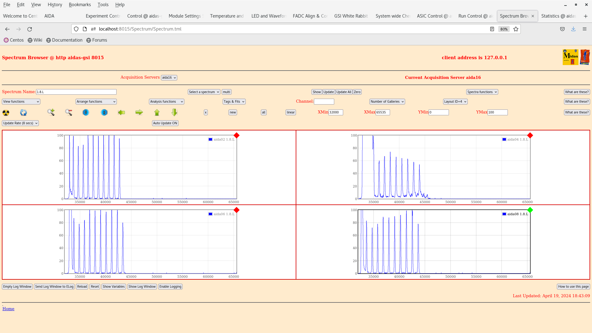
18.43 DAQ ends OK file S100_alpha/R13_20

      per p+n FEE64 1.8.L spectra - attachment 15

18.55 Current status

      FEE64 power ON
      DSSSD bias ON

      All FEE64 slow comparator 0x14

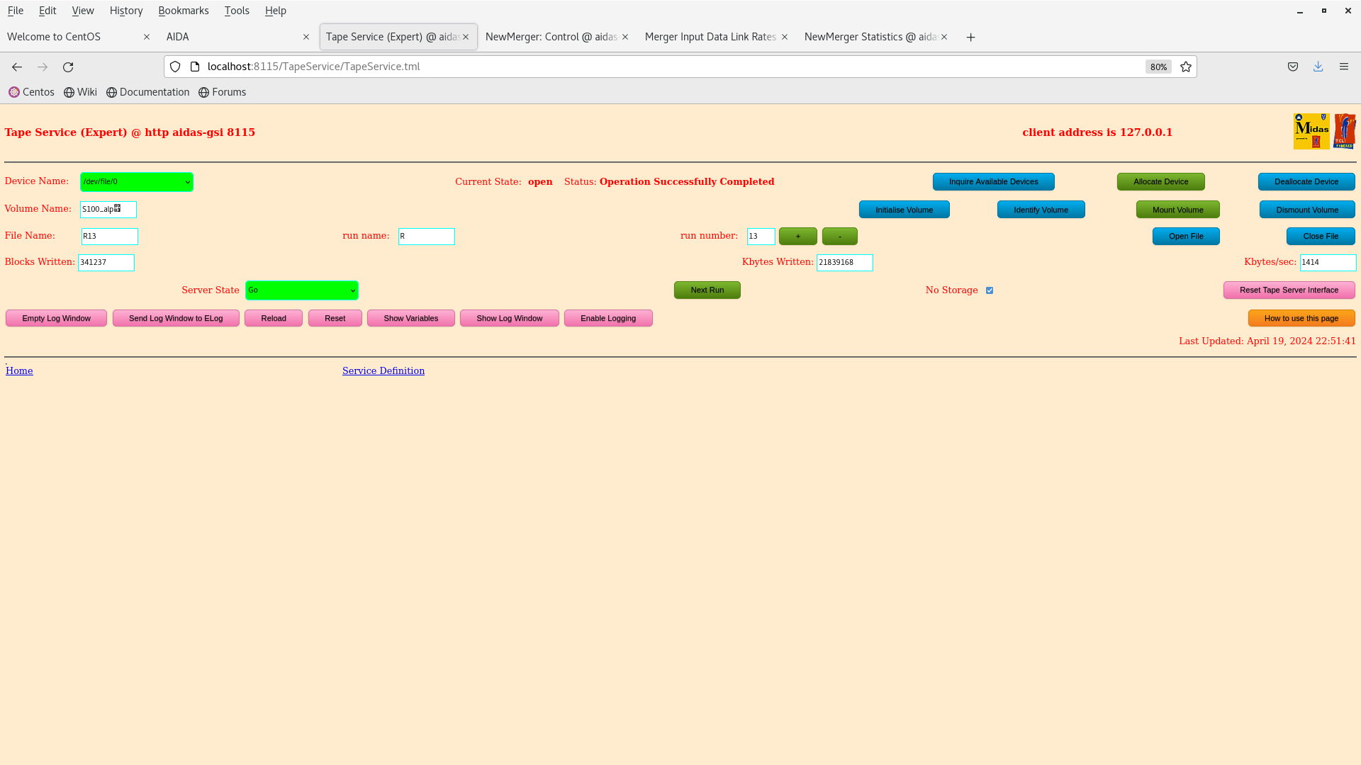
      DAQ going -> Merger -> TapeServer (no storage mode) -> MBS ( but data stream not yet being read by MBS )


To Do

- S4 currently closed/controlled access for FRS startup

If we have access to S4 tomorrow

- switch test - to test + ( not critical )
- test AIDA interlock
- further alpha background?


22.47 DSSSD bias & leakage current OK - attachments 16-17

      FEE64 temps OK - attachment 18
       *except* aida02 ASIC temp - known fault

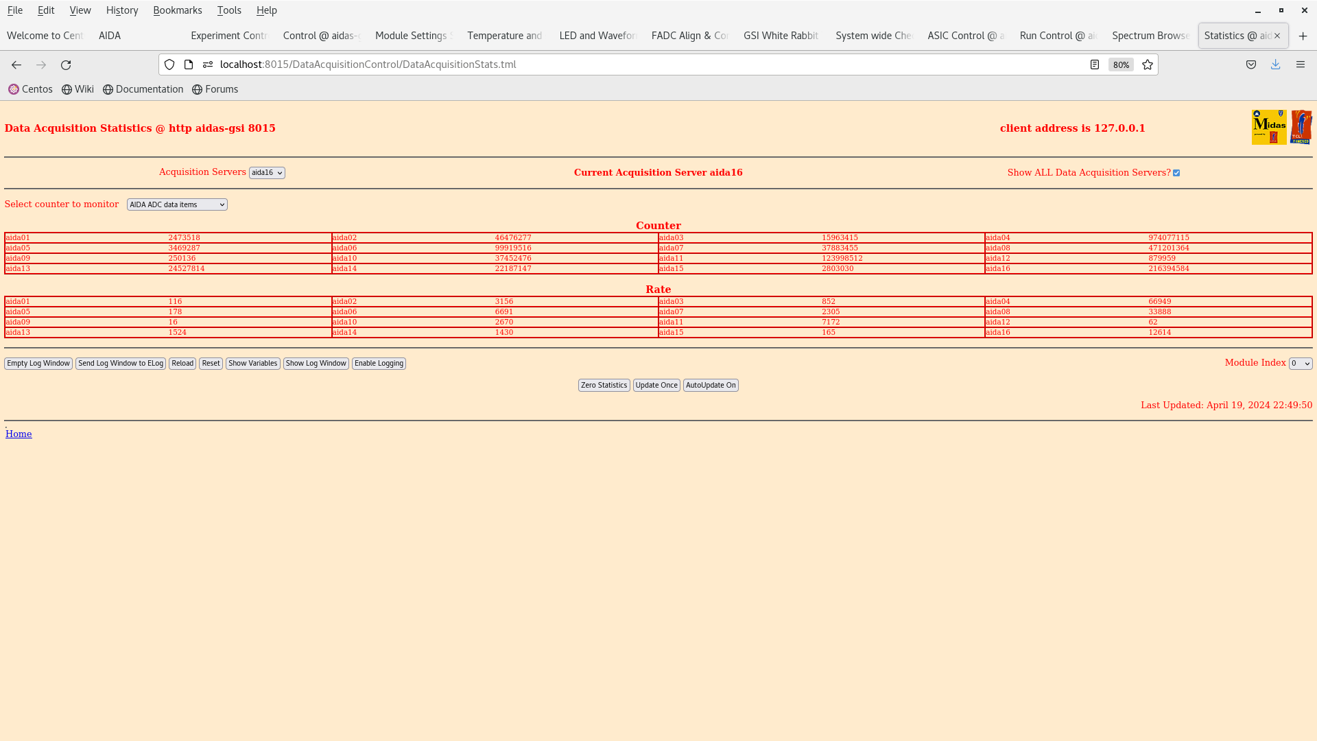
      ADC data item stats - attachment 19

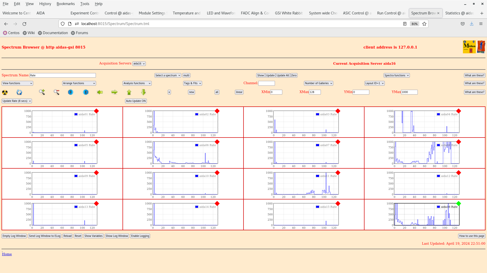
      per FEE64 Rate spectra - attachment 20

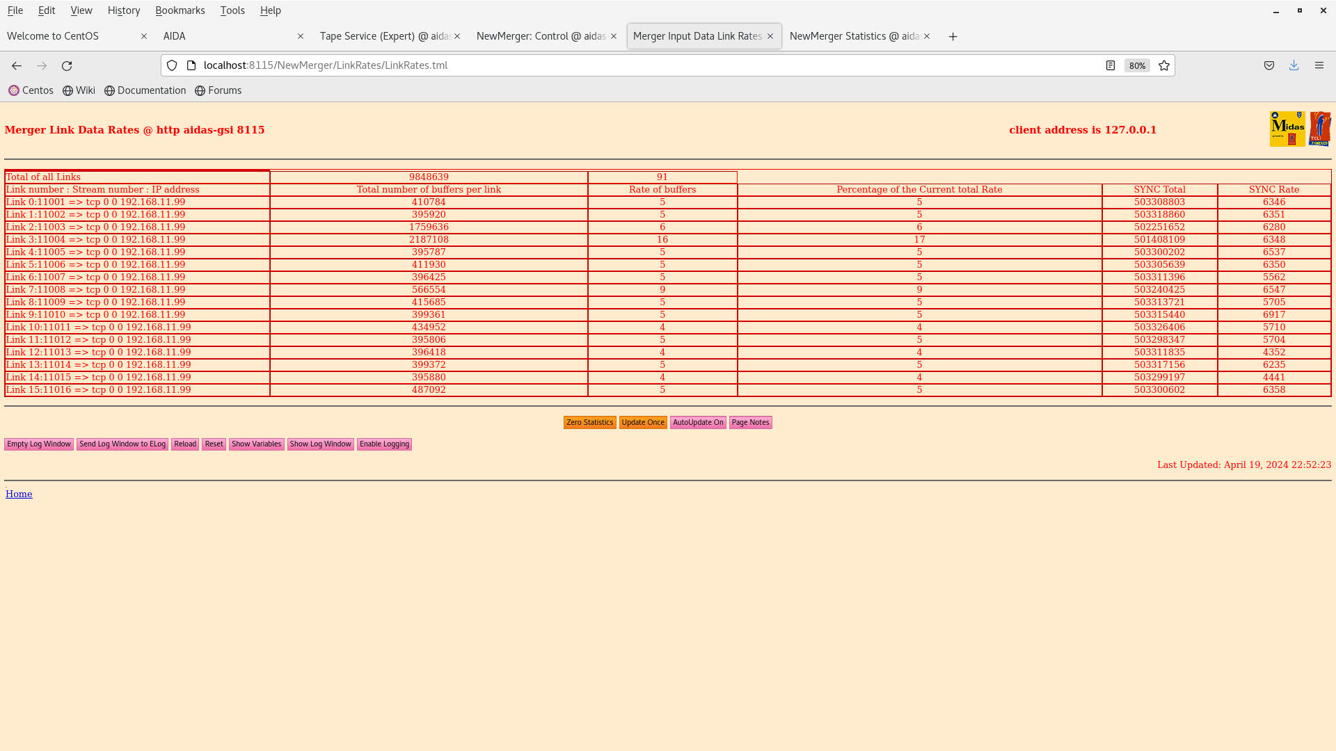
      Data link, Tape Server & Merger - attachments 21-23
|
| Attachment 1: Screenshot_from_2024-04-19_14-56-51.png
|
|
| Attachment 2: Screenshot_from_2024-04-19_14-57-04.png
|
|
| Attachment 3: Screenshot_from_2024-04-19_14-58-27.png
|
|
| Attachment 4: Screenshot_from_2024-04-19_14-58-23.png
|
|
| Attachment 5: Screenshot_from_2024-04-19_14-59-02.png
|
|
| Attachment 6: Screenshot_from_2024-04-19_15-01-31.png
|
|
| Attachment 7: Screenshot_from_2024-04-19_15-01-17.png
|
|
| Attachment 8: Screenshot_from_2024-04-19_15-01-02.png
|
|
| Attachment 9: Screenshot_from_2024-04-19_15-00-39.png
|
|
| Attachment 10: Screenshot_from_2024-04-19_14-59-51.png
|
|
| Attachment 11: Screenshot_from_2024-04-19_15-02-09.png
|
|
| Attachment 12: Screenshot_from_2024-04-19_15-04-36.png
|
|
| Attachment 13: Screenshot_from_2024-04-19_15-03-48.png
|
|
| Attachment 14: Screenshot_from_2024-04-19_16-56-36.png
|
|
| Attachment 15: Screenshot_from_2024-04-19_18-45-05.png
|
|
| Attachment 16: Screenshot_from_2024-04-19_22-47-43.png
|
|
| Attachment 17: Screenshot_from_2024-04-19_22-48-52.png
|
|
| Attachment 18: Screenshot_from_2024-04-19_22-49-31.png
|
|
| Attachment 19: Screenshot_from_2024-04-19_22-50-15.png
|
|
| Attachment 20: Screenshot_from_2024-04-19_22-51-23.png
|
|
| Attachment 21: Screenshot_from_2024-04-19_22-52-39.png
|
|
| Attachment 22: Screenshot_from_2024-04-19_22-52-14.png
|
|
| Attachment 23: Screenshot_from_2024-04-19_22-51-55.png
|

|
|
630
|
Tue May 7 13:25:00 2024 |
JB, CC, NH, HMA | Tuesday 6 May - dismount snout |
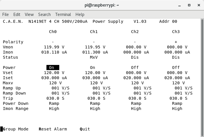
Status before dismount
14:26 DSSSD#1 119.99 V @ 17.968 uA
DSSSD#2 119.95 V @ 11.212 uA
Leakage currents slightly elevated from Monday.
S4 temperature at 26 °C.
14:30 Detectors being debiased. All relay channels turned off. Voltages and currents of both DSSSDs to 0.
Plan:
- Dismount snout.
- Open up and remove BB7 and Upstream bPlast - leave AIDA 1 and 2 in place if possible.
|
| Attachment 1: Screenshot_from_2024-05-07_14-25-52.png
|

|
| Attachment 2: Screenshot_from_2024-05-07_14-29-13.png
|
|
|
555
|
Tue Apr 2 12:36:25 2024 |
JB, CC, NH | Installing FEE64s of DSSSD2 cont. |
Some additional checks
- check 'top hat' electrical isolators are correctly installed at each of the 4x mounting points of the AIDA snout assembly
- check snout is electrically isolated with respect to AIDA support assembly/stand, bPlas PCBs/cabling/ground/drain wires and BB7
- check LK1 installed aida02 or aida04 *and* aida06 or aida08 ( I assume these are the n+n Ohmic FEE64s? )
- check LK3 installed bottom, middle p+n junction FEE64s ( i.e. LK3 installed on 2 of 16 FEE64 adaptor PCBs )
- check FEE64 power cables are paired correctly, e.g. aida02 & aida04, aida01 & aida03 etc. Remember that the numbering of the power cables at the FEE64 PSUs may no longer correspond to which FEE64 is actually connected to that cable
- check test and test - cable daisy chains are removed
- check ground cabling attachment to Lemo 00.250 connectors is tight - they have tendency to loosen with handling
|
|
685
|
Thu Jan 9 15:43:17 2025 |
JB, CC, MP | Timing test platform moved in |
16:30 We moved the platform in. The system was still biased and the DAQ was still running.
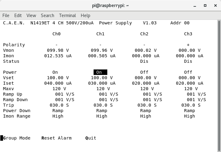
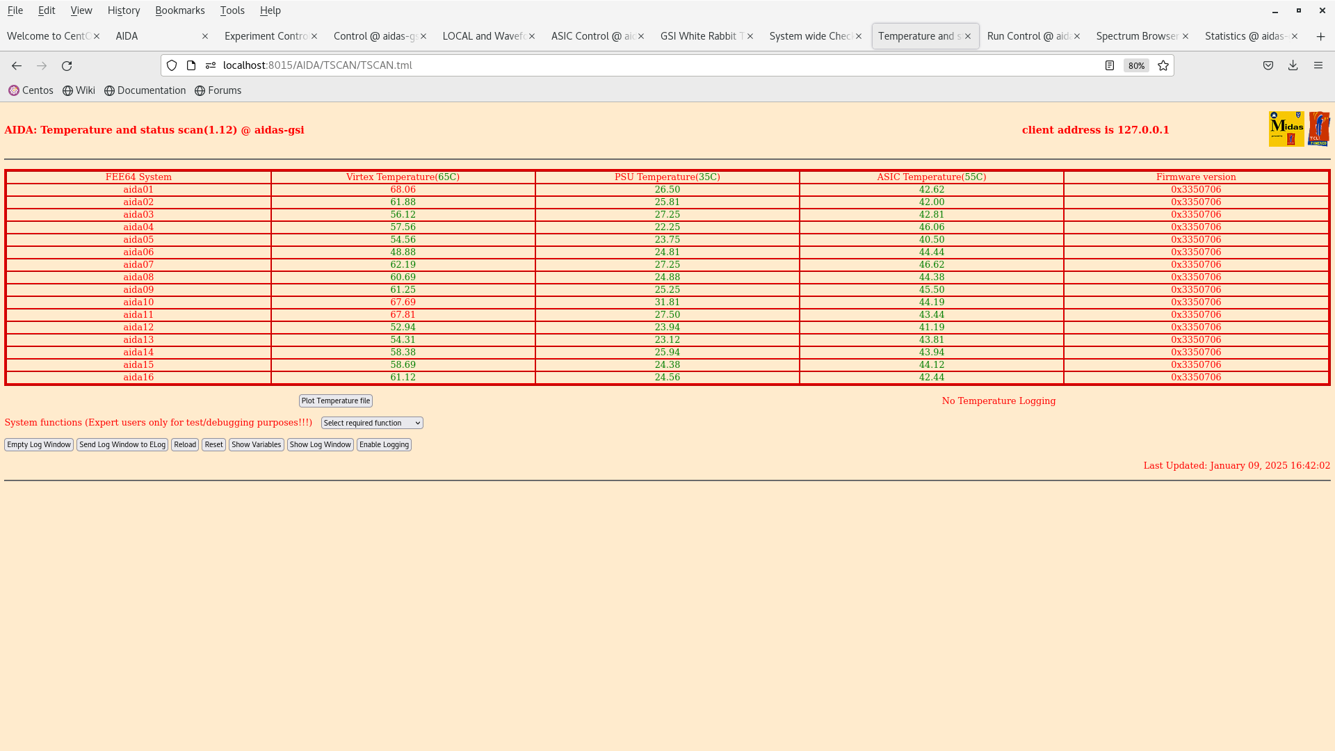
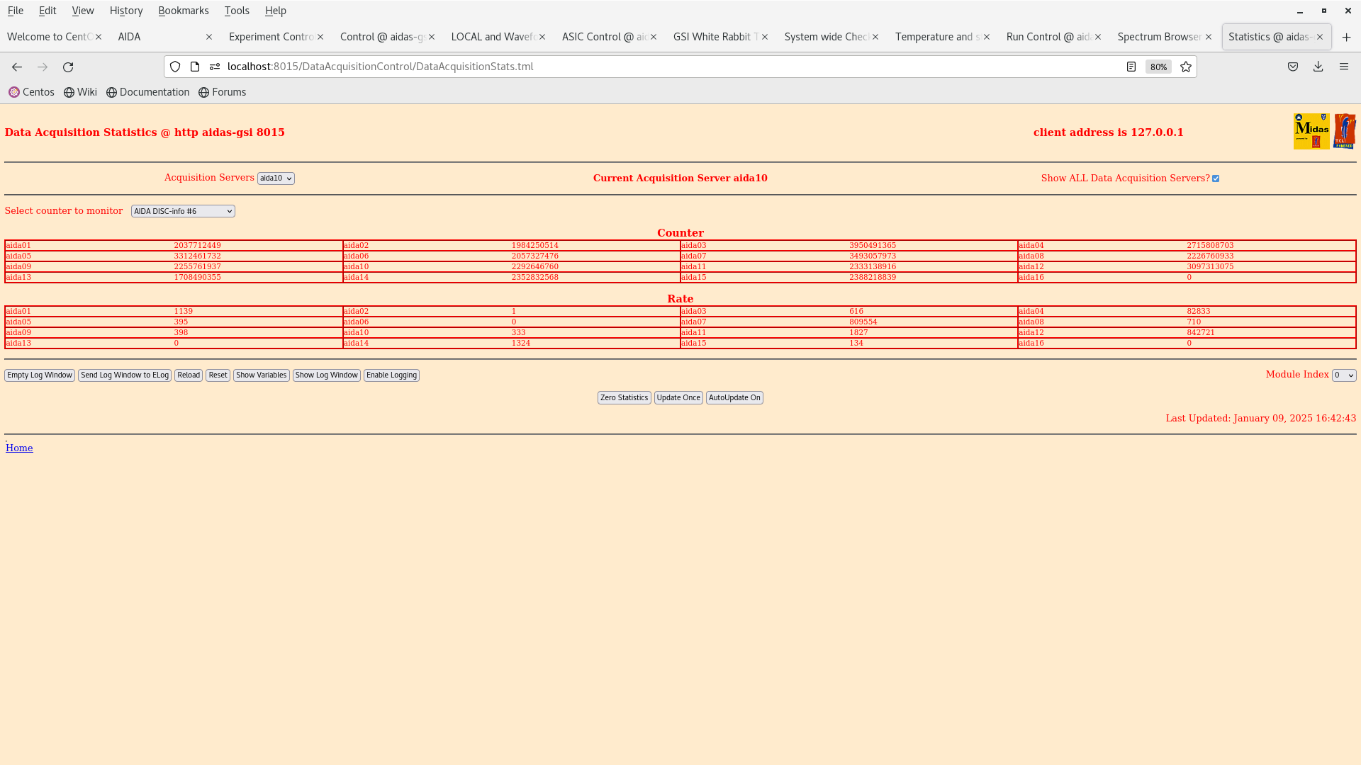
The system seems to be okay, temperatures OK. Bias voltage OK 685/1 and 685/2. Two FEEs - aida07 and aida12 are receiving a lot of trigger data items from the fast discriminator. This is already a bit worrying. 685/3 |
| Attachment 1: Screenshot_from_2025-01-09_16-41-48.png
|
|
| Attachment 2: Screenshot_from_2025-01-09_16-42-06.png
|
|
| Attachment 3: Screenshot_from_2025-01-09_16-42-46.png
|
|
|
572
|
Thu Apr 11 22:04:50 2024 |
JB | 12.04.2024 AIDA-bPlast noise optimisation |
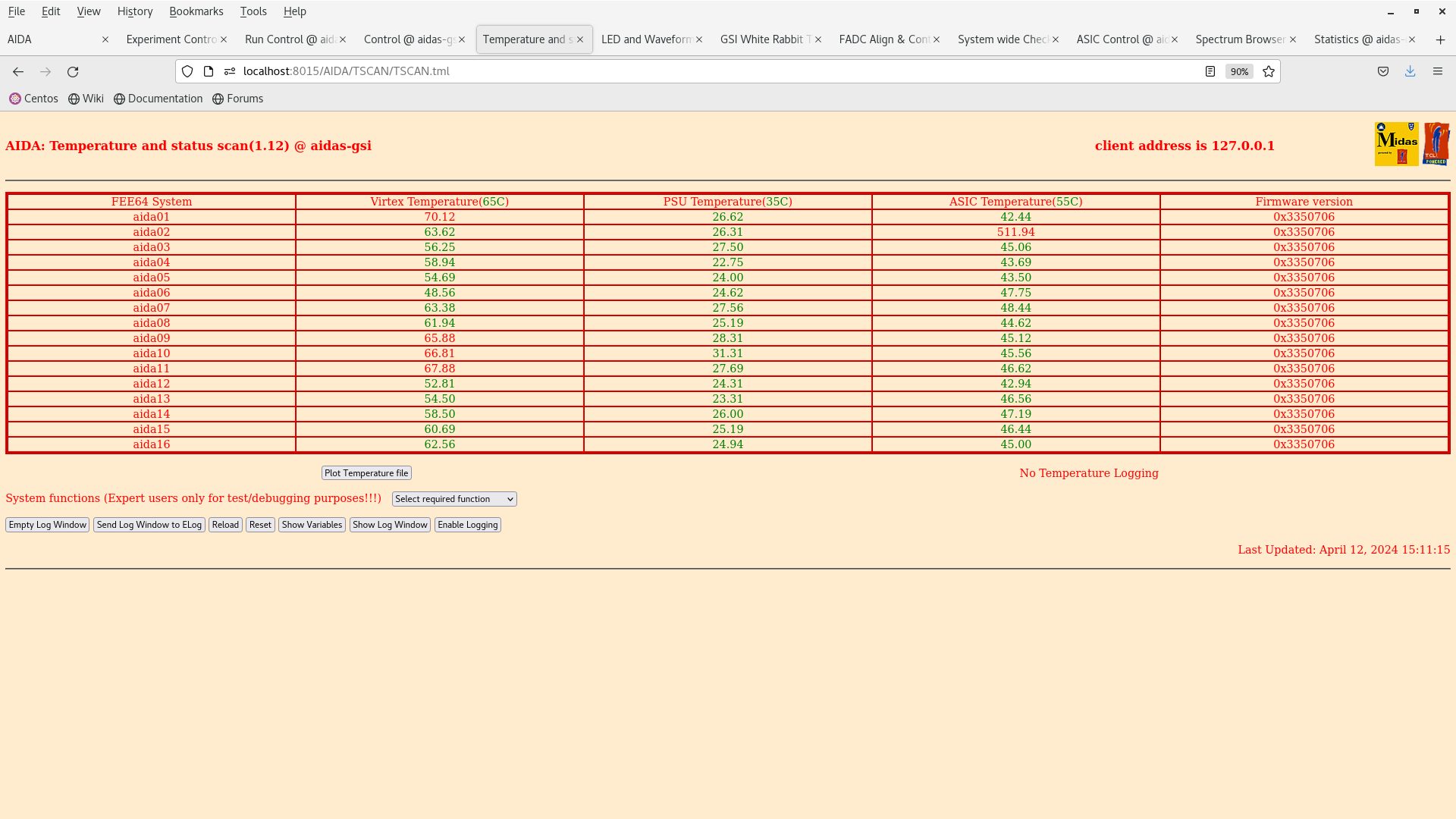
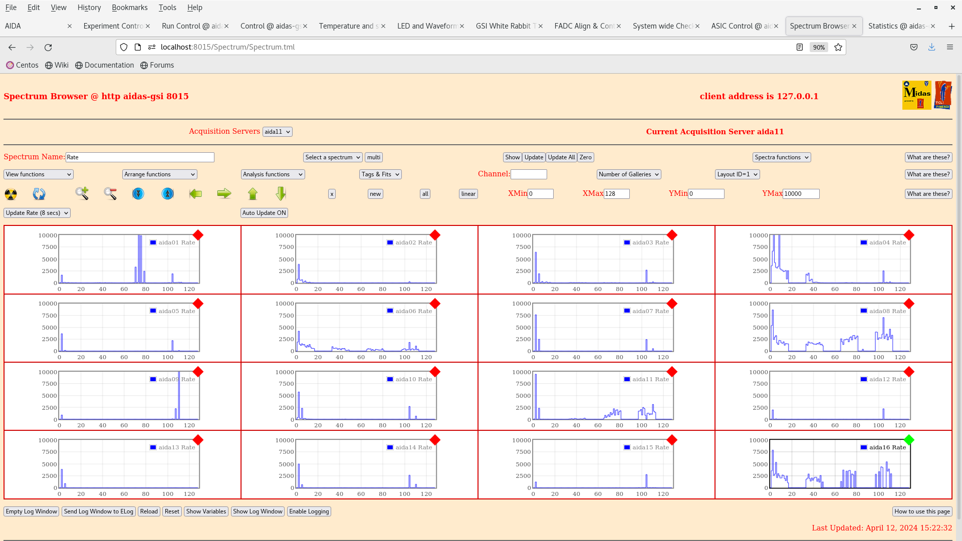
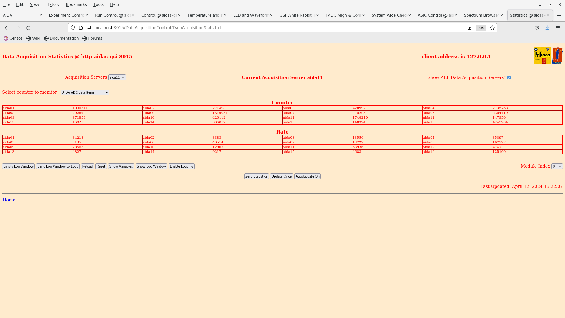
15:00 Platform in, biasing detector. Temp OK Attachment 1. test - Pulser OFF.
Rates somewhat worse than last night - probable contact on grounding of snout. Attachment 3.
Histograms okay, some FEE64s now have hot channels. Attachment 2.
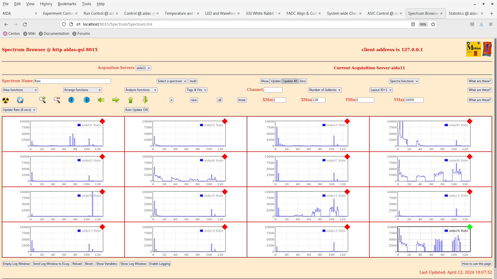
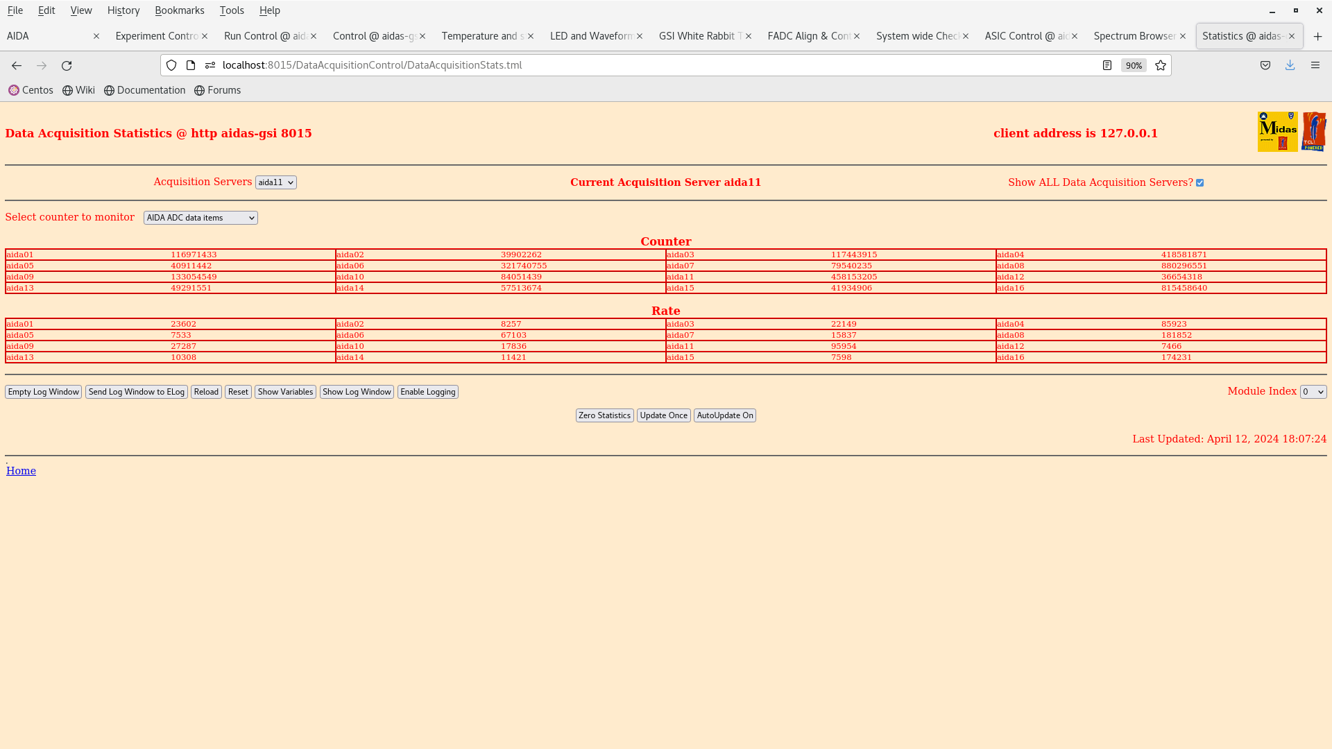
9/16 aidas < 20kHz - max rate 162k
18:06 - powering down detector for the weekend. Overall system is fine, some channels (hot channels) definitely picked up noise, but condition is overall stable over three hours. See atachments 4-5.
TO-DO (kicking the can down the road):
- Some work to do on noise, but we might have to accept the situation as it currently is.
- Implement bPlast trigger scheme. Set bPlast thresholds, get bPlast current draw undercontrol - observe AIDA noise.
- Try different grounding configuration:
- Grounding drain wires to frame. Observe AIDA conditions.
- Reconnect 4V out to R&SRMP4040 common ground with PN 300 PSU as well. Observe AIDA conditions.
|
| Attachment 1: Screenshot_from_2024-04-12_15-11-18.png
|
|
| Attachment 2: Screenshot_from_2024-04-12_15-22-54.png
|
|
| Attachment 3: Screenshot_from_2024-04-12_15-22-26.png
|
|
| Attachment 4: Screenshot_from_2024-04-12_18-07-35.png
|
|
| Attachment 5: Screenshot_from_2024-04-12_18-07-27.png
|
|
|
573
|
Sat Apr 13 14:04:44 2024 |
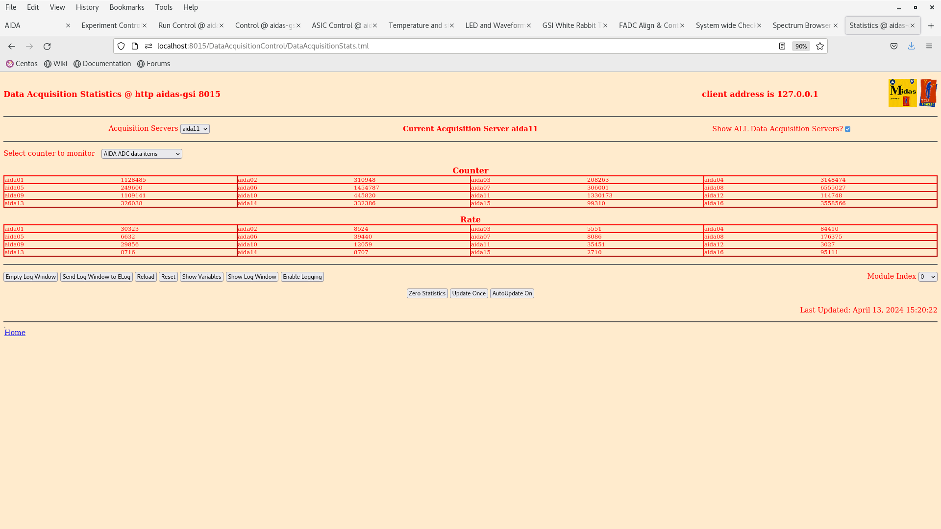
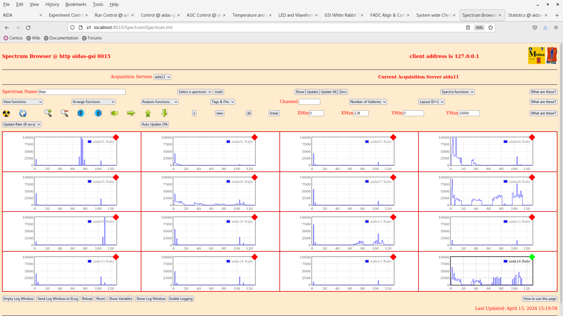
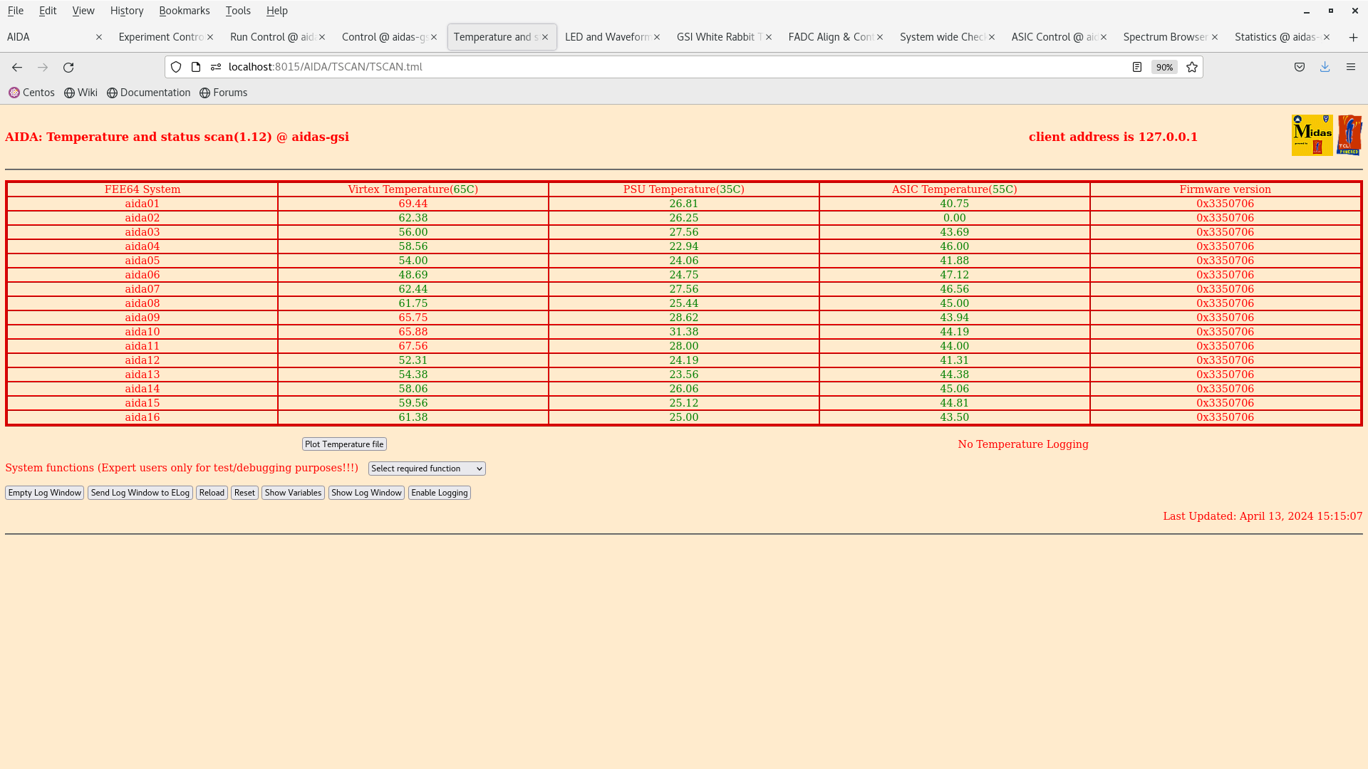
JB | 13 April Noise checks |
15:04 bPlast was left powered over night. Powering up to check noise conditions - also to check shifting of Germanium baseline (no change observed).
TEMP OK.
Noise condition the same as yesterday when platform was moved in. Noise in aida01 and aida09 due to single channel failures (?). Attachments 1-3.
9/16 <20kHz, max 176k
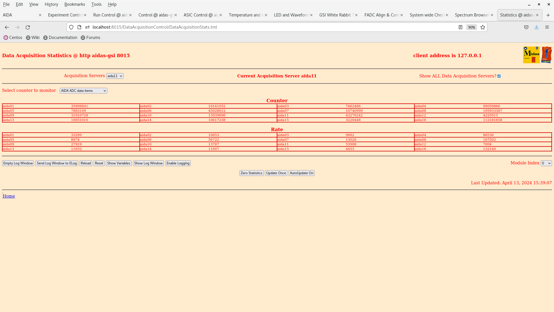
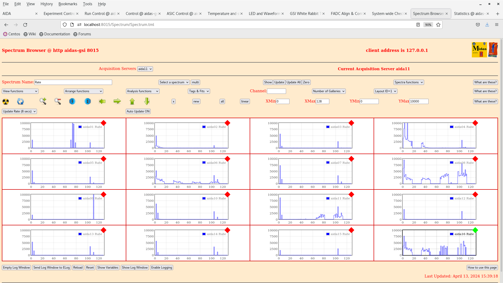
15:30 Changed drainwires ground from 4V (Ch3) -> 29.5V (Ch4) out on R&SMP4040 PSU. Attachments 4-5.
No change in noise observed.
9/16 <20kHz, max 187k
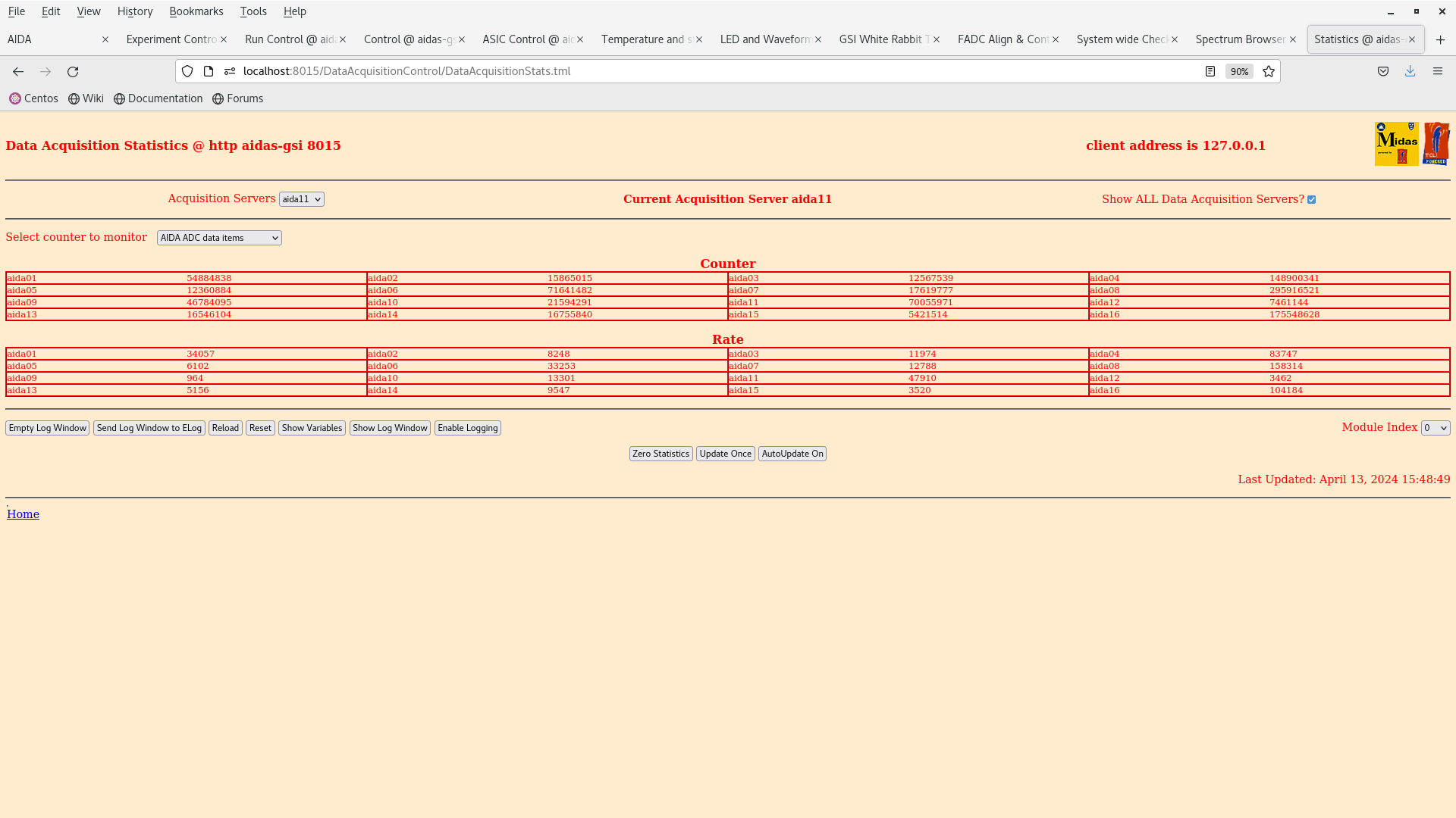
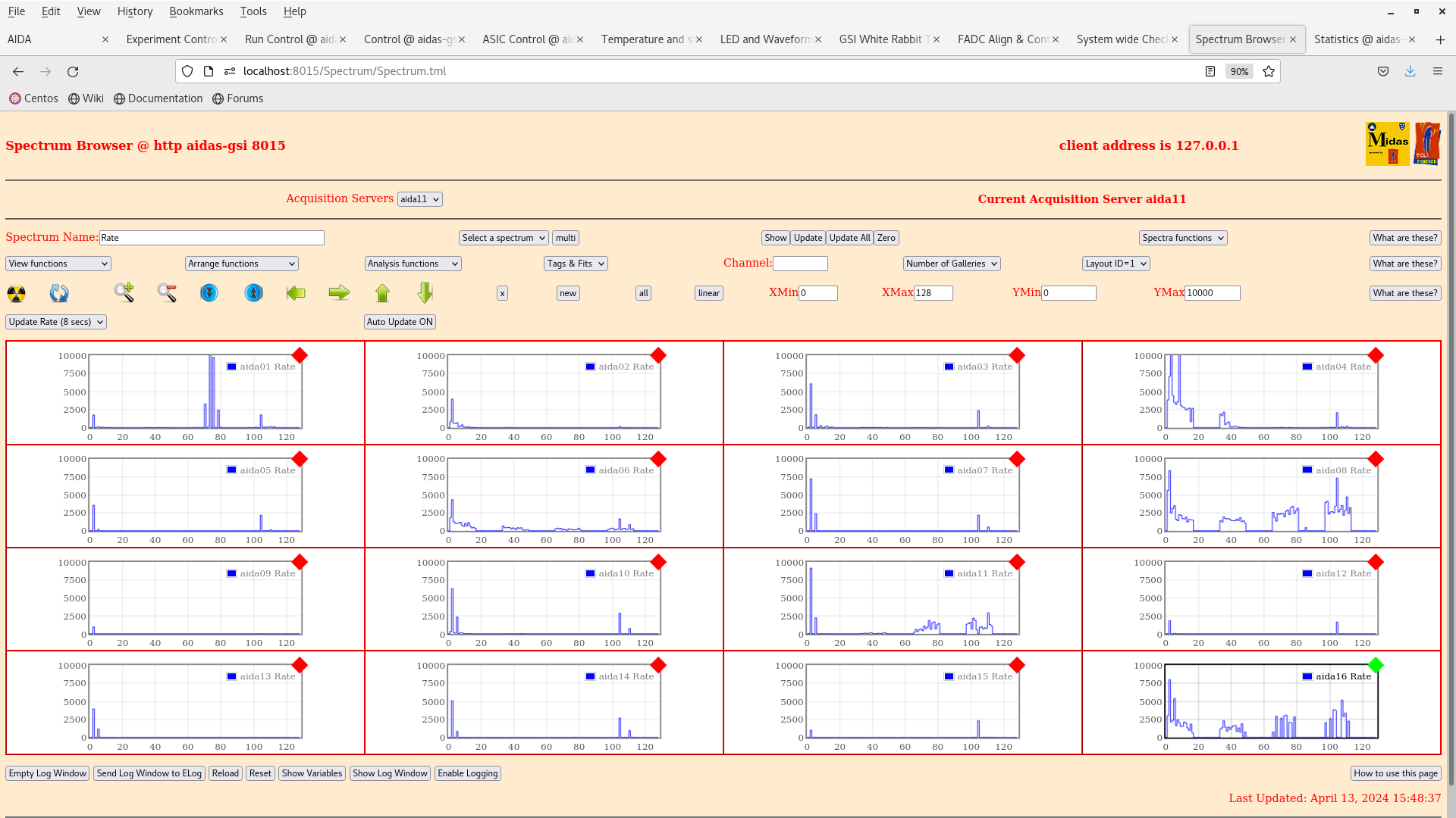
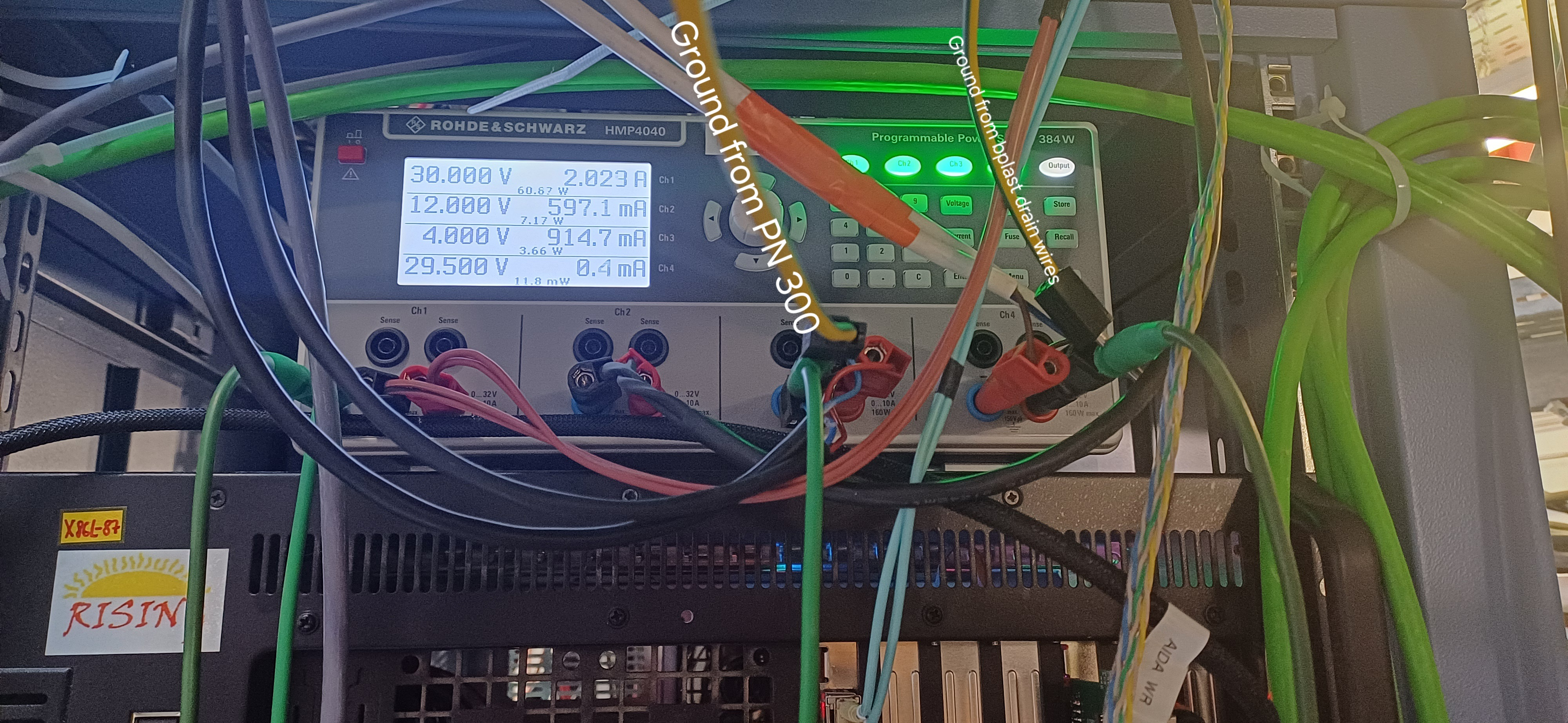
15:49 Connected PN 300 ground to R&SMP4040 4V (Ch3) output. Noise decreased in many channels aida09 does not have a noisy channel anymore (??). Attachments 6-7.
10/16 <20kHz, max 158k.
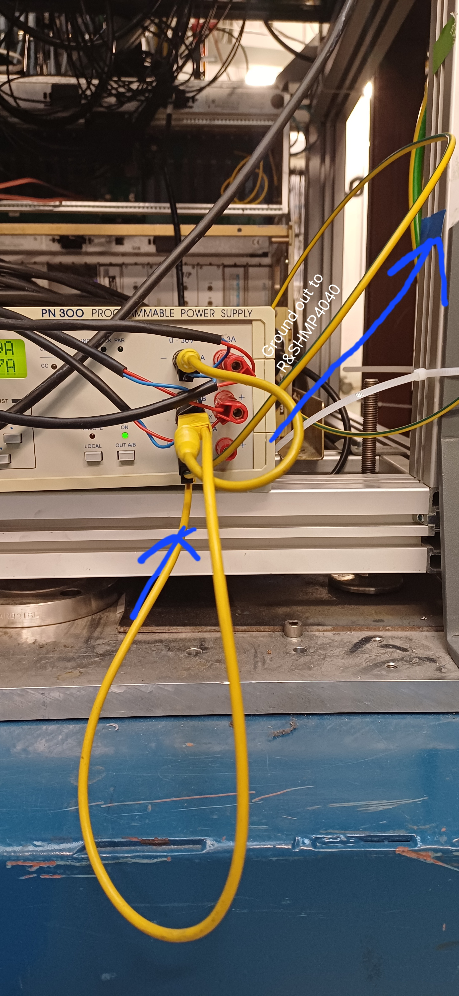
Current bPlast grounding scheme in attachments 8-9.
|
| Attachment 1: Screenshot_from_2024-04-13_15-21-34.png
|
|
| Attachment 2: Screenshot_from_2024-04-13_15-20-28.png
|
|
| Attachment 3: Screenshot_from_2024-04-13_15-15-14.png
|
|
| Attachment 4: Screenshot_from_2024-04-13_15-40-59.png
|
|
| Attachment 5: Screenshot_from_2024-04-13_15-40-56.png
|
|
| Attachment 6: Screenshot_from_2024-04-13_15-48-53.png
|
|
| Attachment 7: Screenshot_from_2024-04-13_15-48-42.png
|
|
| Attachment 8: 20240413_155823.jpg
|
|
| Attachment 9: 20240413_160214.jpg
|
|
|
669
|
Wed Aug 14 12:40:11 2024 |
JB | Repaired DSSSD delivery 14.09.2024 |
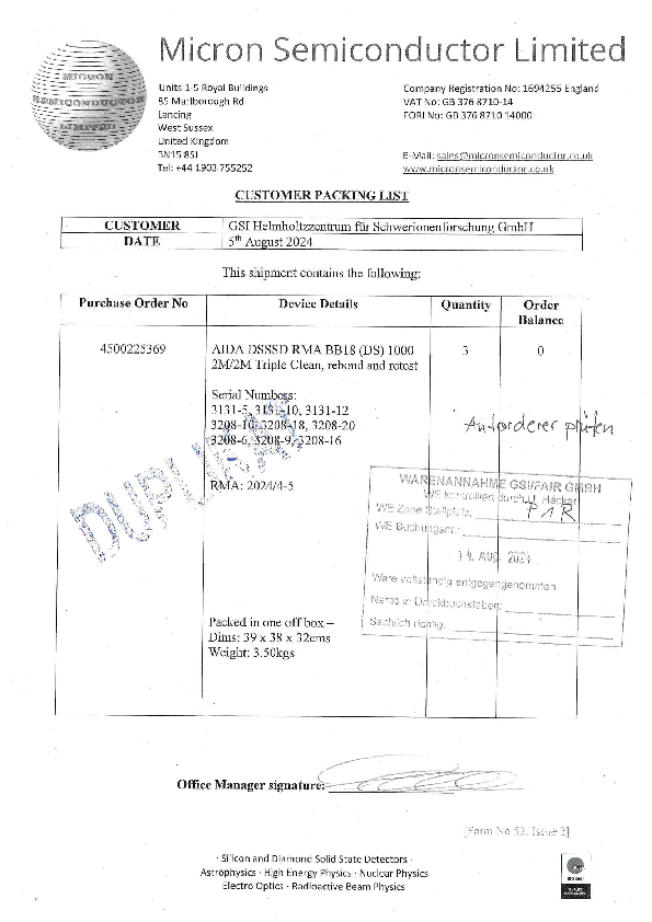
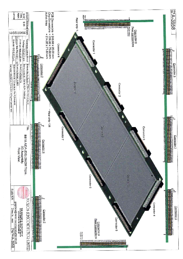
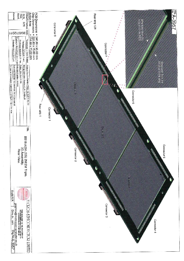
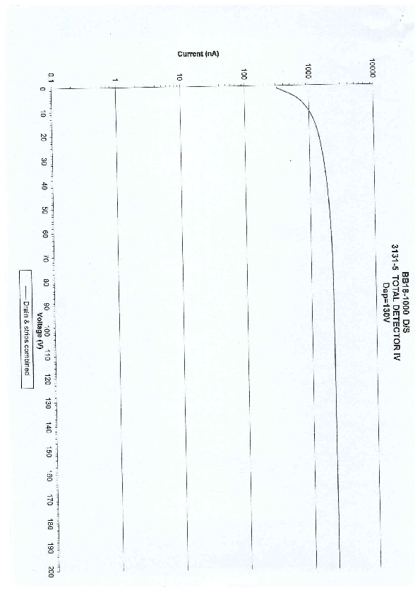
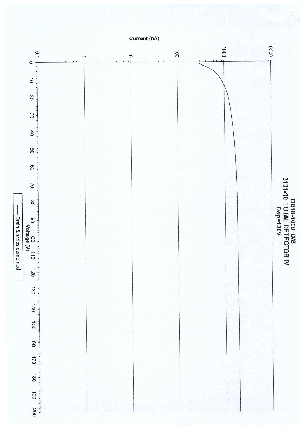
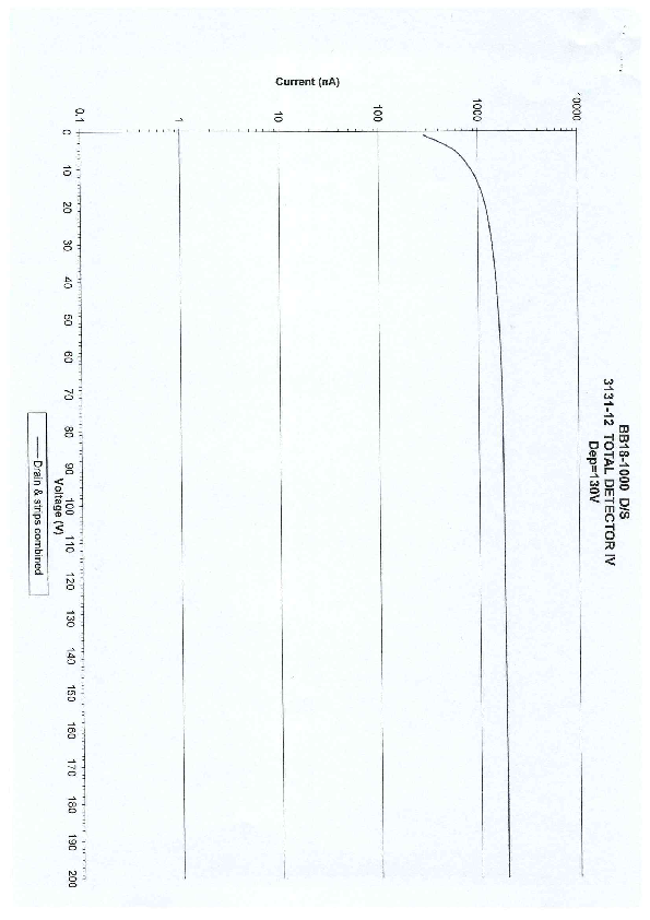
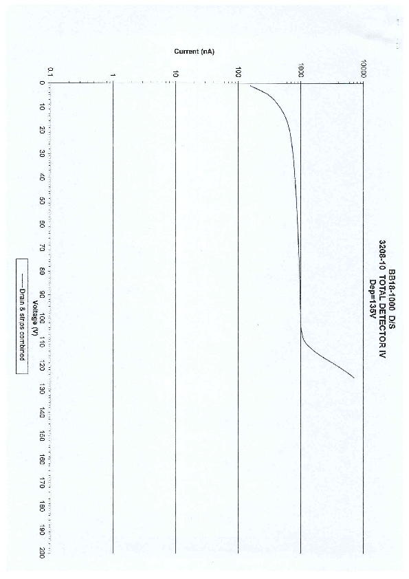
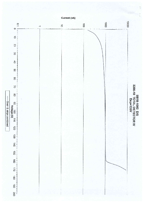
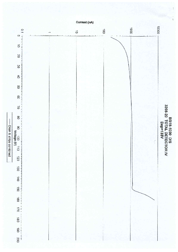
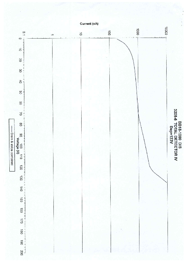
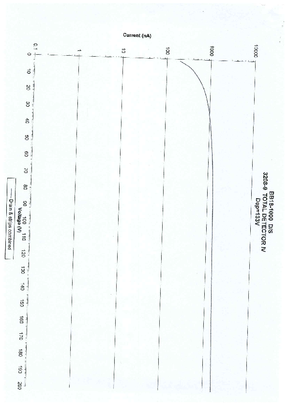
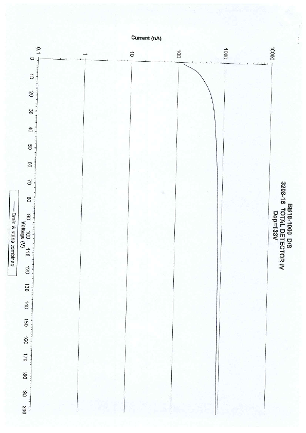
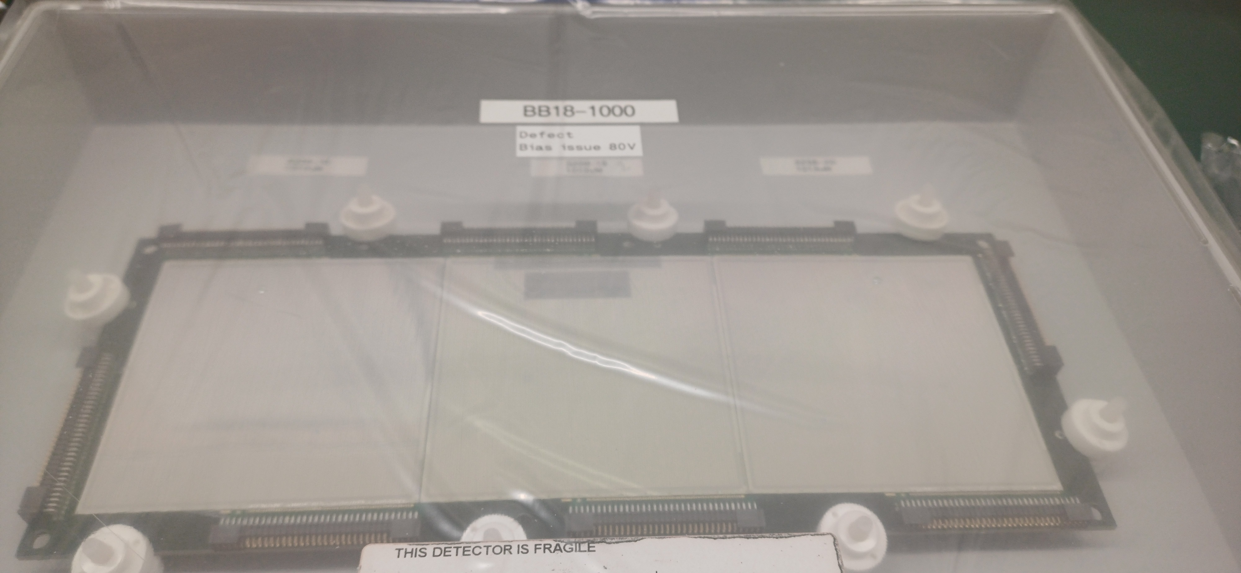
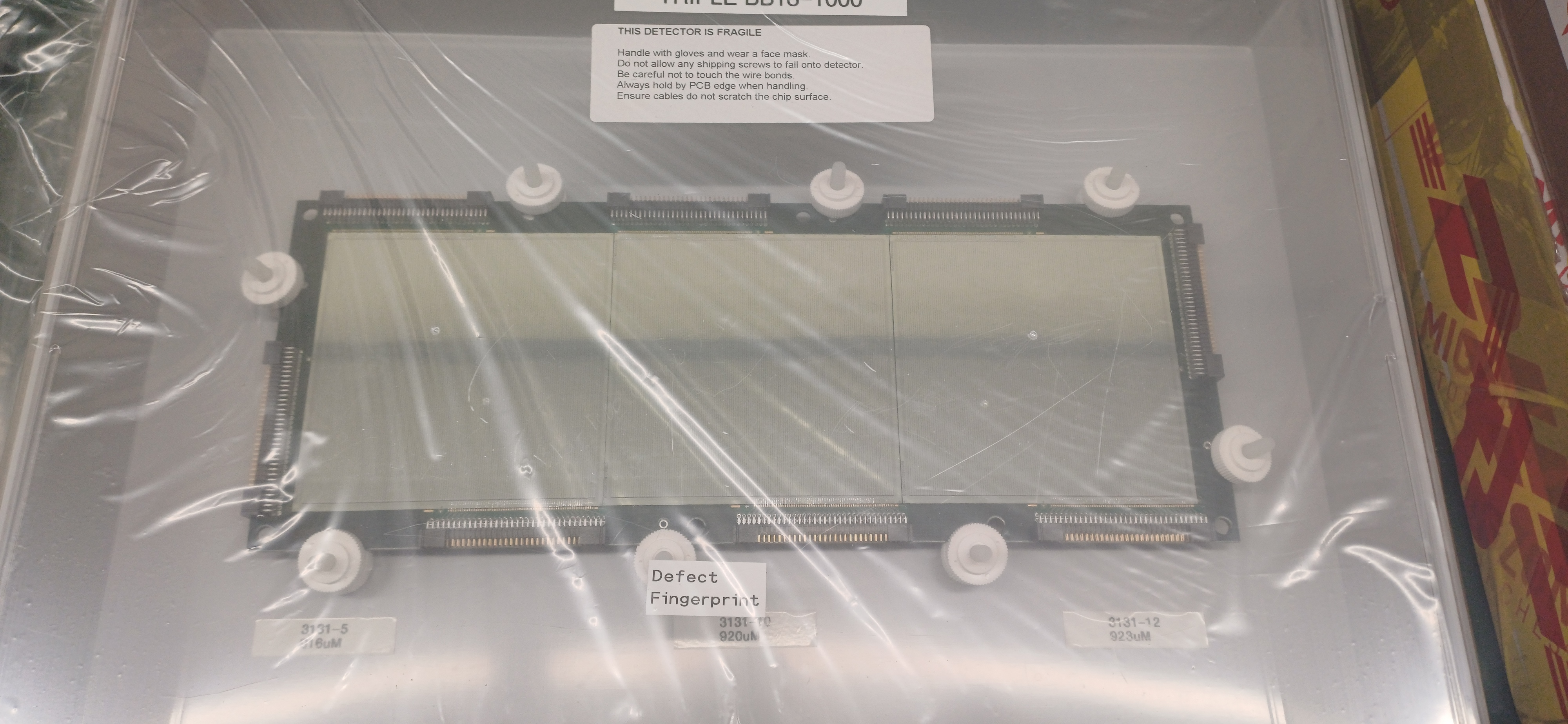
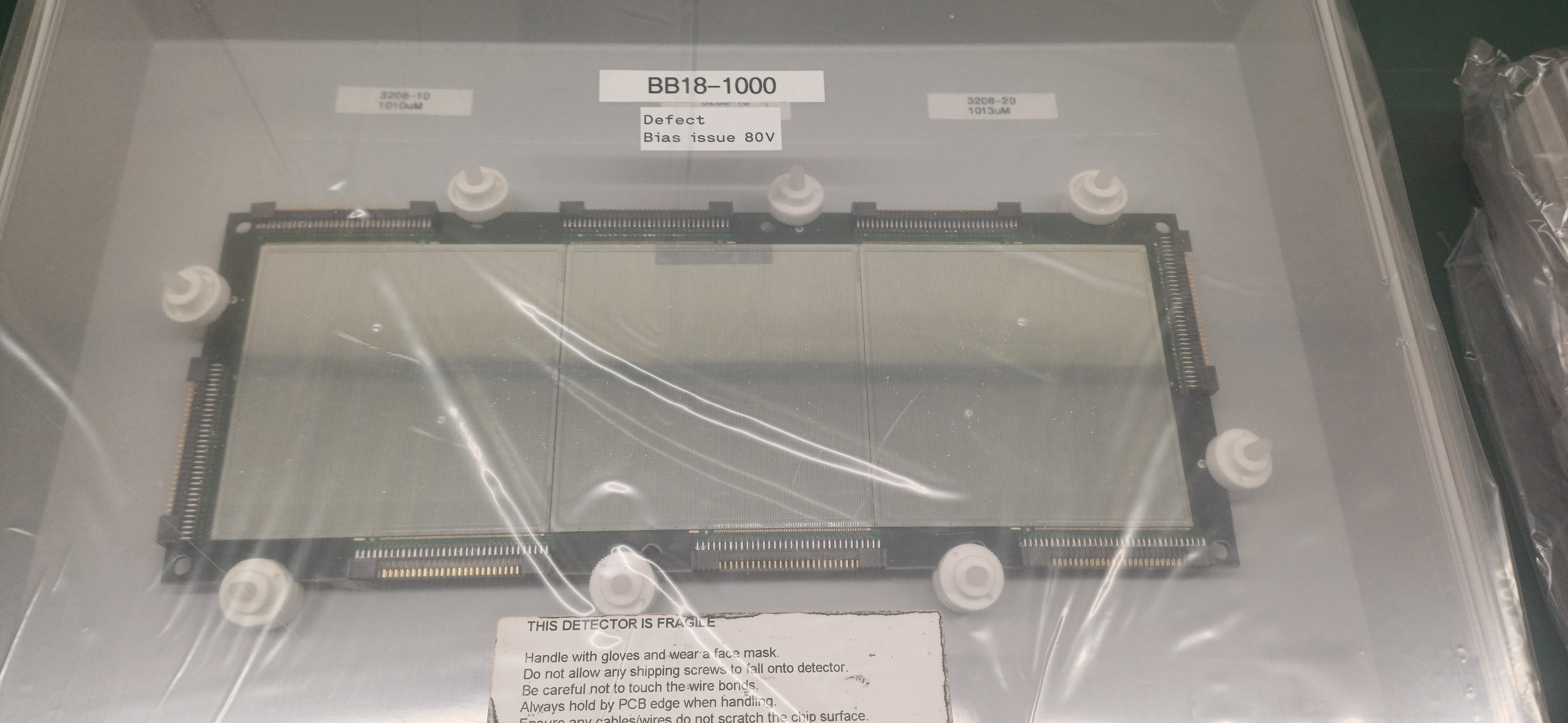
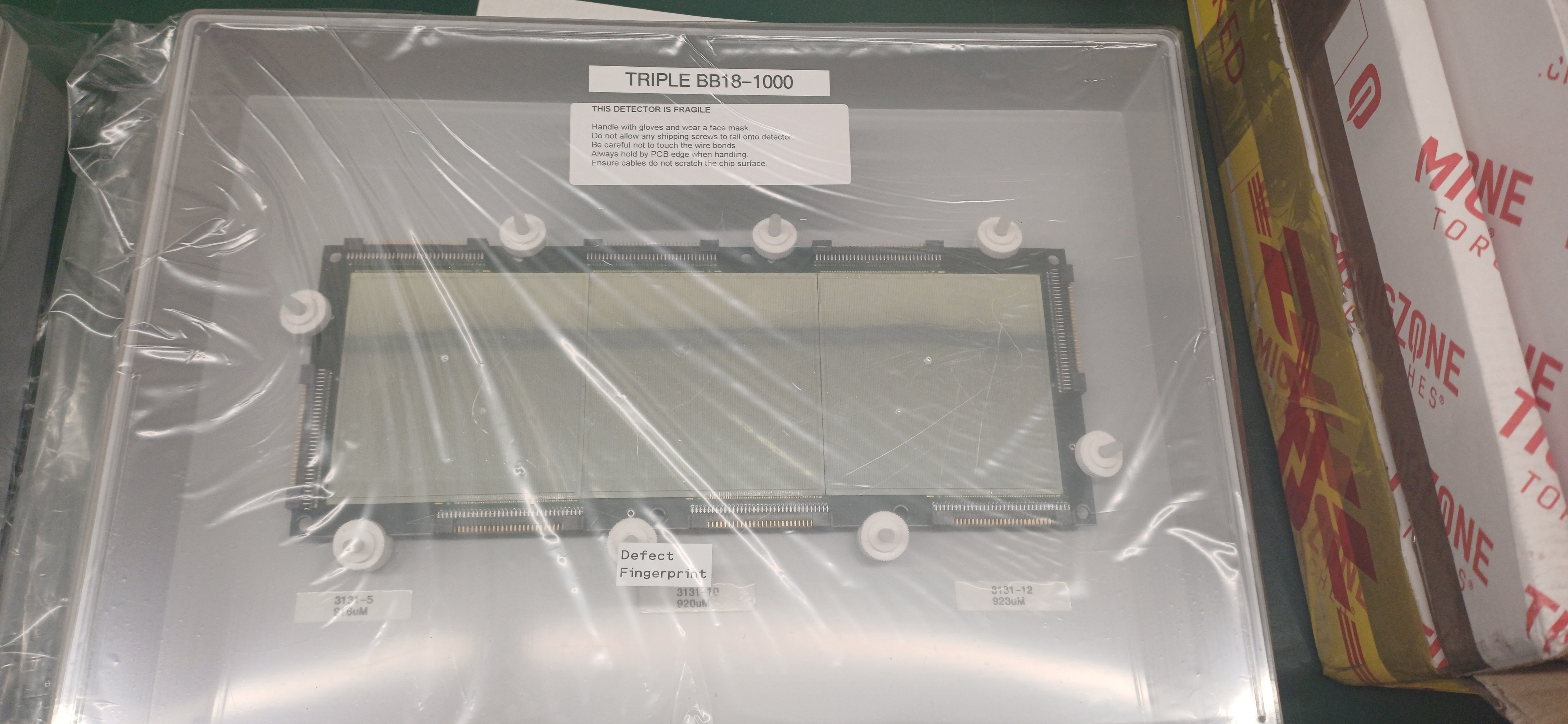
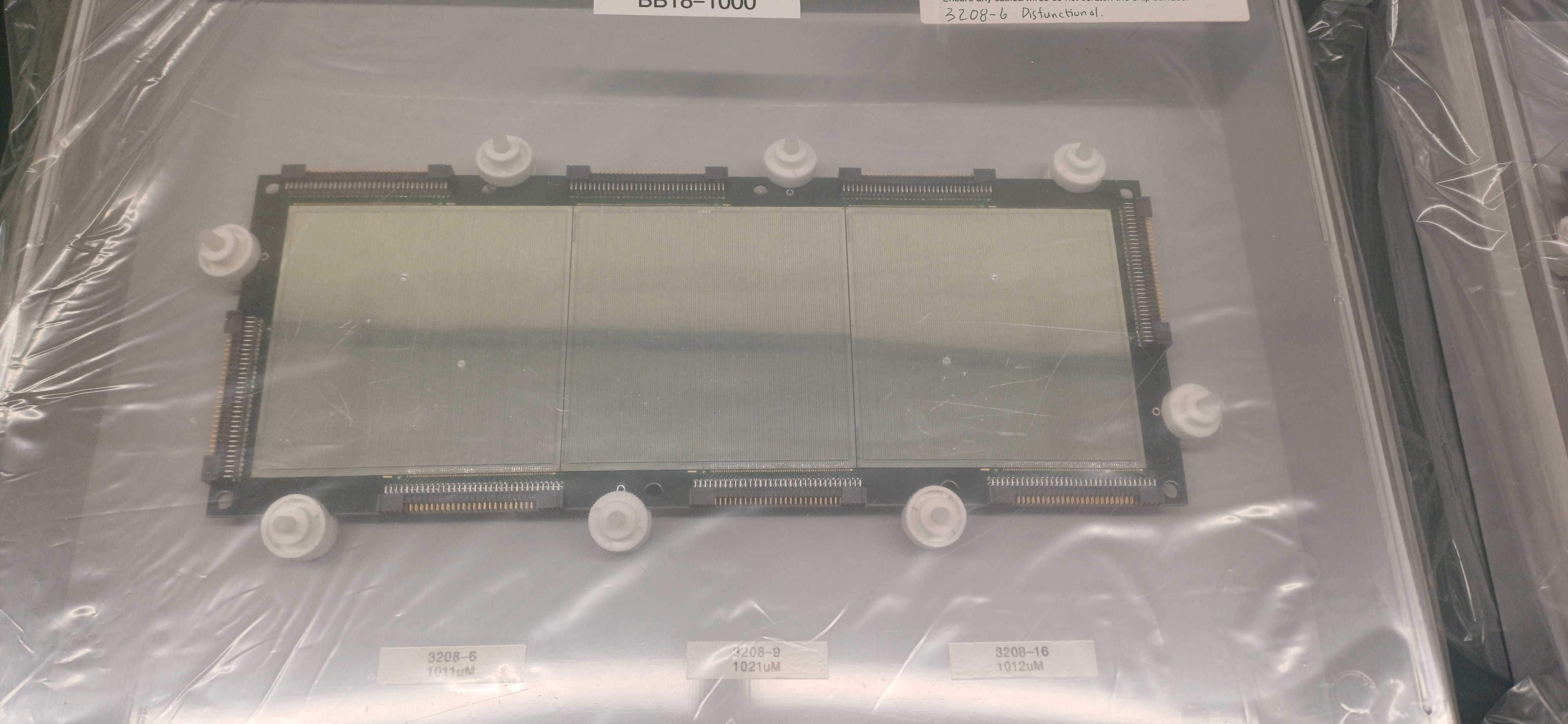
Three BB18-1000 triples AIDAs collected on 14.09.2024
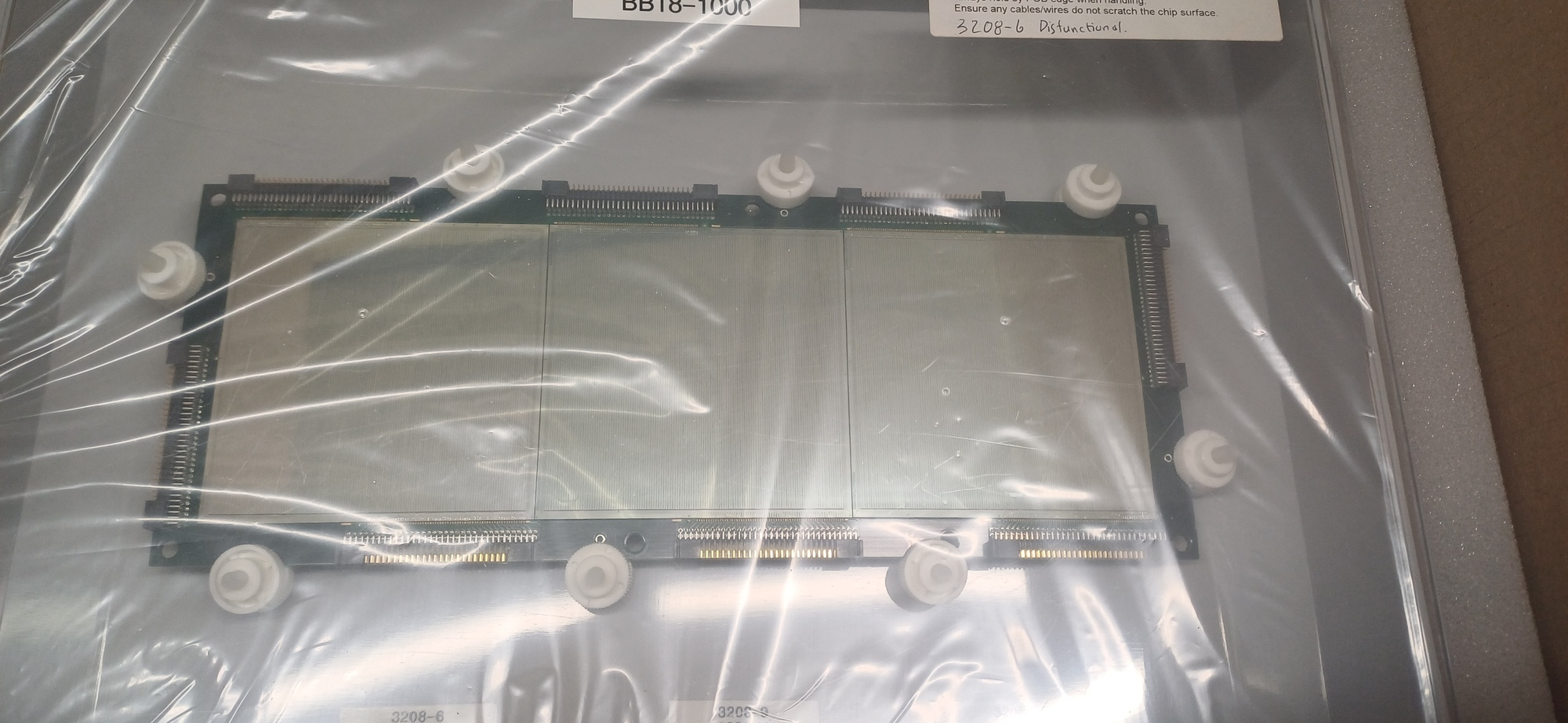
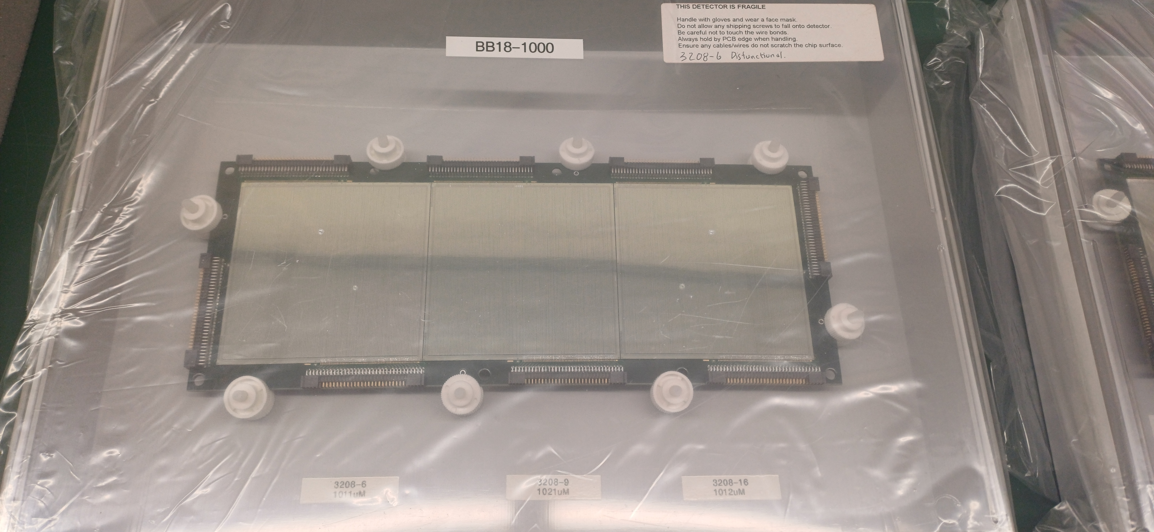
Find attached visual of the wafer and bond wire + factory bias tests accompanying the DSSSDs. elog:669/1 elog:669/2 elog:669/3
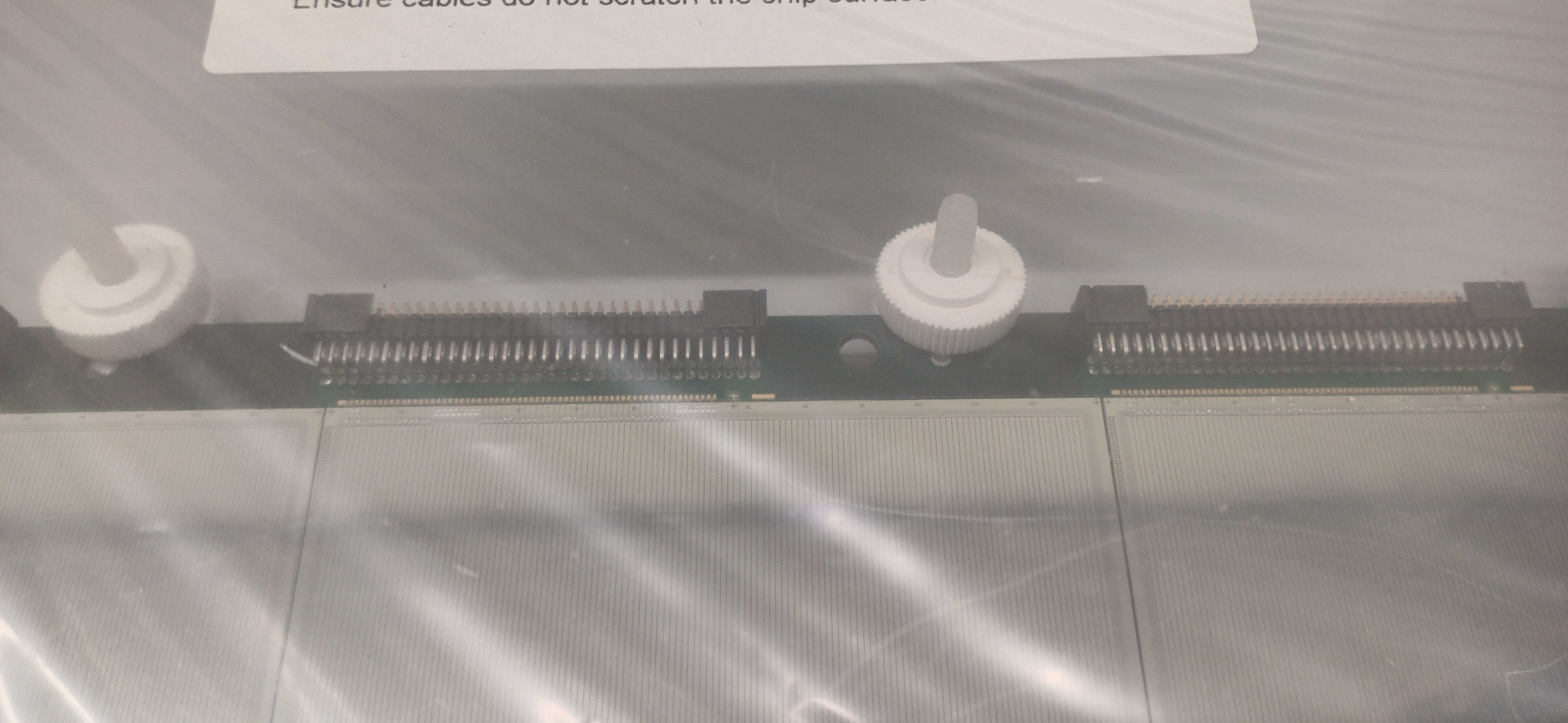
Visual inspection carried out showed that bond wires have been fixed + fingerprint on one DSSSD removed and wires repaired. elog:669/4 elog:669/5 elog:669/6 elog:669/7 elog:669/8 elog:669/9 elog:669/10 elog:669/11
DSSSD 1 (defect bias issue 80V): 3208-10 / 3208-18 / 3208-20
DSSSD 2 (3208-6 dysfunctional): 3208-6 / 3208-9 / 3208-16
DSSSD 3 (defect fingerprint): 3131-5 / 3131-10 / 3131-12
|
| Attachment 1: doc00418120240814132739.pdf
|
|
| Attachment 2: doc00418020240814132419.pdf
|
|
| Attachment 3: doc00417920240814132325.pdf
|
|
| Attachment 4: 20240814_132617.jpg
|
|
| Attachment 5: 20240814_133316.jpg
|
|
| Attachment 6: 20240814_133306.jpg
|
|
| Attachment 7: 20240814_133225.jpg
|
|
| Attachment 8: 20240814_133321.jpg
|
|
| Attachment 9: 20240814_133328.jpg
|
|
| Attachment 10: 20240814_133300.jpg
|
|
| Attachment 11: 20240814_133313.jpg
|
|