| ID |
Date |
Author |
Subject |
|
68
|
Mon Dec 3 17:59:48 2018 |
Thomas Chillery, Raffaele Buompane | Calibration with alpha source - 0.9um mylar on Far S2 |
On 28/11/2018:
After pulser walkthrough (see eLog entry #67)
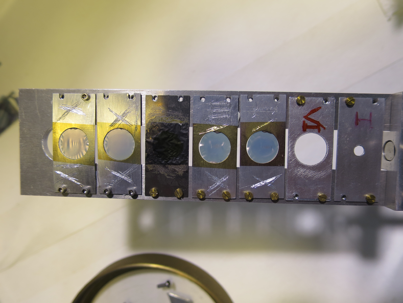
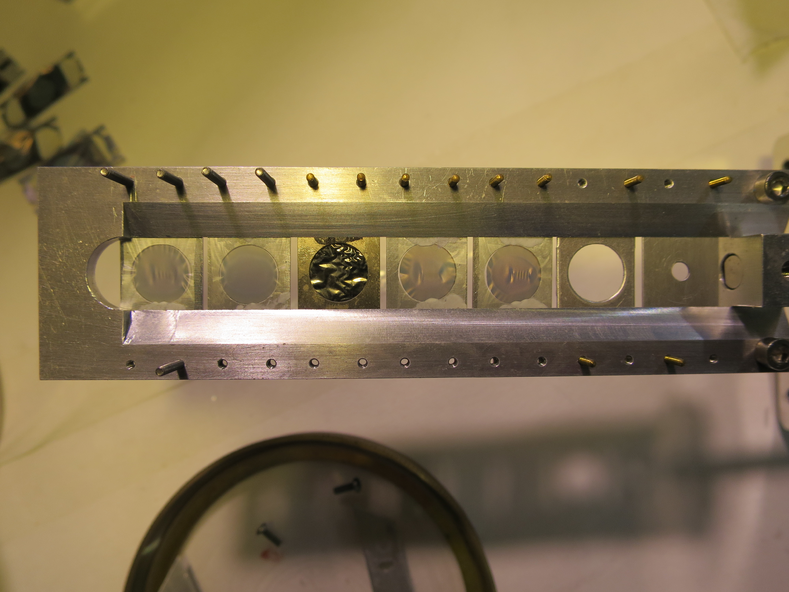
Dismounted targets from ladder - see picture 1 and 2 for upstream and downstream sides respectively
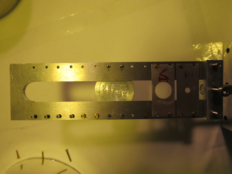
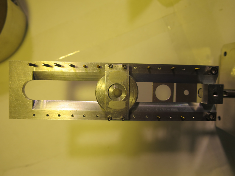
Mounted alpha source on ladder - see pictures 3 and 4 for upstream and downstream sides respectively
New target ladder configuration is now:
| Target Position |
Target |
| 1 |
Blank 3mm |
| 2 |
Blank 10mm |
| 3 |
Nothing |
| 4 |
Alpha-Source |
| 5 |
Nothing |
| 6 |
Nothing |
| 7 |
Nothing |
Dismounted thin CH2 target 50 - it was still attached to the collimator.
Remounted far S2 with 0.9um mylar, remounted far iris arm.
In air, pressures (mBar):
- TPU1 > 1000
- TPU2 > 1000
- TPD1 = 170 (above range)
- TPD2 = 73 (above range)
- CHUP = Sensor Off
- CHDW = No Sensor
Far S2 biased to -130.0V, leak I = 1.55uA. Diode biased to -70.1V, leak I = 0.01uA.
Ratemeter ~9200Hz.
Switched off detectors.
12:05 Ecodry 1 and 2 on. Started opening manual valve.
12:20 Manual valve opened fully, T1600 backing valve opened. Started turbos.
12:30 Pressures (mBar):
- TPU1 = 3.0e-5
- TPU2 = 5.1e-6
- TPD1 = 5.1e-6
- TPD2 = 7.5e-6
- CHUP = Sensor Off
- CHDW = No Sensor
Far S2 biased to -130.0V, leak I = 1.52uA. Diode biased to -70.1V, leak I = 0.01uA.
Rate meter ~ 7000Hz. Ladder set to position #4 - alpha source. Rate meter still ~ 7000Hz.
Run # 181128123940
- Run time: 3428s
- Pulser ON, as before
- Alpha-source
- S2 mylar: 0.9um
- DT ~ 22%
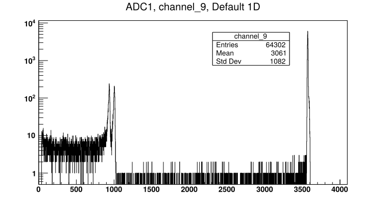
- See attached picture 5 for sample Far S2 front strip spectrum
|
| Attachment 1: IMG_3305.JPG
|
|
| Attachment 2: IMG_3307.JPG
|
|
| Attachment 3: IMG_3315.JPG
|
|
| Attachment 4: IMG_3313.JPG
|
|
| Attachment 5: 181128123940_ADC1_Ch9.png
|
|
|
69
|
Mon Dec 3 18:15:42 2018 |
Thomas Chillery, Raffaele Buompane | Calibration with alpha source - no mylar on Far S2 |
On 28/11/2018:
At 13:35: Far S2 bias = -130.0V, leak I = 1.55uA. Diode bias = -70.1V, leak I = 0.00uA.
Pressures (mBar):
- TPU1 = 3.3e-6
- TPU2 = 9,3e-7
- TPD1 = 1.2e-6
- TPD2 = 1.3e-6
- CHUP = Sensor Off
- CHDW = No Sensor
Switched off detectors, switched off pumps, closed manual and T1600 backing valves. Vented chamber.
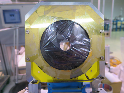
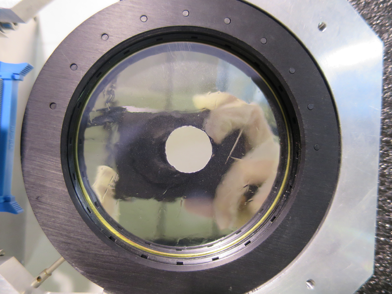
Removed 0.9um mylar from far S2 - see attached picture 1 for mylar pre-removal. Removed far iris arm from downstream lid -> set iris to open position. Replaced far iris actuator with blank flange.
Remounted far S2 and far preamp - preamp still draws correct currents.
In air: Far S2 bias = -130.0V, leak I = 1.65uA. Diode bias = -70.1V, leak I = 0.01uA. Rate meter ~ 5500Hz.
Detectors bias off.
15:05 Ecodry 1 and 2 on, started opening manual valve.
15:20 Manual valve fully opened, T1600 backing valve opened, turbos on
15:30 Pressures (mBar):
- TPU1 = 2.2e-5
- TPU2 = 4.4e-6
- TPD1 = 4.0e-6
- TPD2 = 4.7e-6
- CHUP = Sensor Off
- CHDW = No Sensor
Far S2 biased to 130.0V, leak I = 1.59uA. Diode biased to -70.1V, leak I = 0.00uA. Ratemeter ~ 7000Hz.
Run numbers 181128153642, 181128161647, and 181128161758 are all alpha calibration runs. However DAQ connection was lost before the first run was started so the run time is not recorded for these.
Run # 181128162552
- Run time: 1408s
- Pulser ON, as before
- Alpha source
- S2 mylar: NONE
- DT ~ 20%
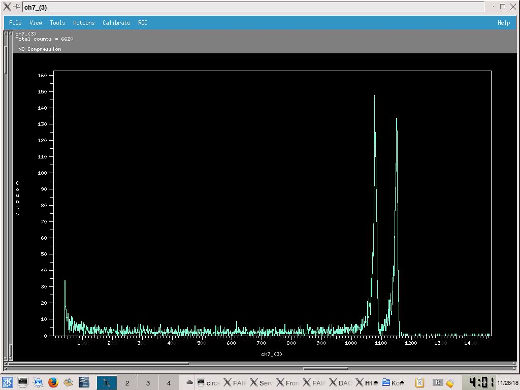
- See attached picture 2 for sample spectra from ADC2 Ch7 (ADC 3 in FAIR DAQ file browser)
16:45 Far S2 bias = -130.0V, leak I = 1.61uA. diode bias = -70.1V, leak I = 0.00uA.
Pressures (mBar):
- TPU1 = 2.8e-6
- TPU2 = 8.8e-7
- TPD1 = 1.2e-6
- TPD2 = 1.2e-6
- CHUP = Sensor Off
- CHDW = No Sensor
Switched off detectors, closed valves, turned off pumps, vented chamber.
|
| Attachment 1: IMG_3337.JPG
|
|
| Attachment 2: 182812_S2_Alpha_NoMylar.jpg
|
|
|
70
|
Mon Dec 3 18:30:53 2018 |
Thomas Chillery, Raffaele Buompane | Calibration with alpha source - 12um mylar on Far S2 |
On 28/11/2018:
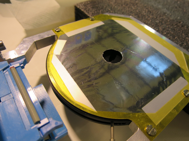
Mounted 12um mylar in front of far S2 - see attached pictures 1 and 2
In air: Far S2 biased to -130.0V, leak I = 1.61uA. Diode biased to -70.1V, leak I = 0.01uA -> 0.00uA. Rate meter ~ 4500Hz.
Detectors switched off
17:50 started Ecodry 1 and 2, started opening manual valve.
18:00 Manual valve fully opened, T1600 backing valve opened, Turbos switched on.
Once pressures ~ 1e-5mBar, far S2 bias = -130.0V, leak I = 1.59uA. Diode bias = -70.1V, leak I = 0.00uA.
18:08 Pressures (mBar):
- TPU1 = 3.0e-5
- TPU2 = 6.0e-5
- TPD1 = 5.2e-6
- TPD2 = 8.7e-6
- CHUP = Sensor Off
- CHDW = No Sensor
Run # 181128181421
- Run time: 1799s
- Pulser ON, as before
- Alpha source
- S2 mylar: 12um
- DT ~ 12%
Started overnight run:
Run # 181128184505
- Run time: 51706s
- Pulser ON, as before
- Alpha source
- S2 mylar: 12um
- DT ~ 8%
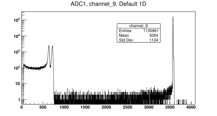
- See attached picture 3 for sample far S2 front strip spectrum
18:50 End of day check:
Far S2 bias = -130.0V, leak I = 1.60uA.
Diode bias = -70.1V, leak I = 0.00uA.
Pressures (mBar):
- TPU1 = 3.8e-6
- TPU2 = 1.2e-6
- TPD1 = 1.4e-6
- TPD2 = 1.6e-6
- CHUP = Sensor Off
- CHDW = No Sensor
On 29/11/2018: Alpha run stopped
9:05: Far S2 bias = -130.0V, leak I = 1.70uA. Diode bias = -70.1V, leak I = 0.00uA.
Detector biases and preamps off.
Pressures (mBar):
- TPU1 = 7.6e-7
- TPU2 = 3.5e-7
- TPD1 = 7.7e-7
- TPD2 = 7.3e-7
- CHUP = Sensor Off
- CHDW = No Sensor
Closed manual and T1600 backing valves. Stopped turbos. Stopped Ecodry 1 and 2.
Switched off Nim bin, RAL crate, and CAMAC crate
9:45 Opened venting valve |
| Attachment 1: IMG_3356.JPG
|
|
| Attachment 2: IMG_3363.JPG
|
|
| Attachment 3: 181128184505_ADC1_Ch9.png
|
|
|
71
|
Mon Dec 3 18:45:17 2018 |
Thomas Chillery, Raffaele Buompane | End of beamtime - Module settings |
Diode Ortec 571 Amplifier Settings:
- Fine gain: 10 (0.5 ->1.5)
- Course gain: 50
- Shaping time: 0.5us
- BLR AUTO: ON
- NEG: ON (Instead of POS)
- OUT: ON (Instead of Delay)
- Internal fine gain: 1X
Diode quad TFA settings:
- No clipping cable attached
- Internal jumpers:
- W1: Invert
- W2 and W3: 200ns differentiation
- W4: T2 (not set to 50ns or OUT)
- W5: X5 course gain
Diode quad CFD settings:
- Threshold at minimum: -177.6mV
- Short delay cable attached (1ns)
- Internal jumpers:
- W1: no jumper
- W2: Top
- W3: no jumper
Oscilloscope used: Tektronix TDS 3054B
RAL Crate Configuration:
| RAL Crate Position (from left) |
RAL Module ID |
| 1 |
XV |
| 2 |
II |
| 3 |
XI |
| 4 |
IV |
| 5 |
V |
| 6 |
VI |
| 7 |
VII |
| 8 |
VIII |
| 9 |
X |
| 10 |
XII |
| 11 |
XIII |
| 12 |
R |
| 13 |
S |
| 14 |
Q |
| 15 |
U |
| 16 |
W |
|
|
72
|
Mon Dec 3 18:55:31 2018 |
Thomas Chillery, Raffaele Buompane | End of beamtime - Cleanup |
On 29/11/2018:
Dismounted S2 2323-18 (496um), 12um mylar, diode, and diodes 0.9um mylar.
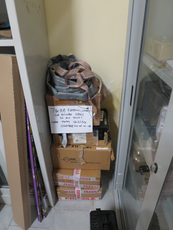
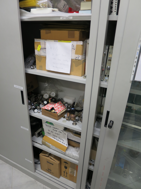
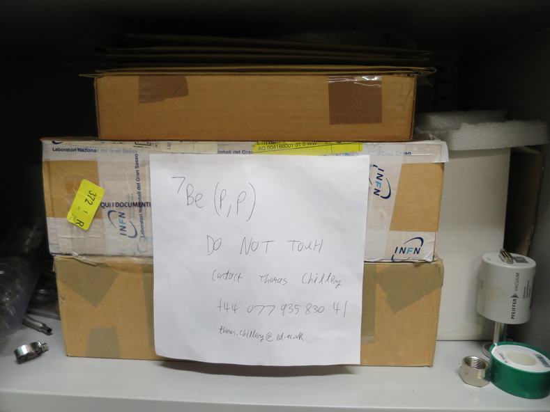
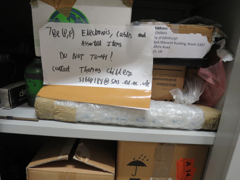
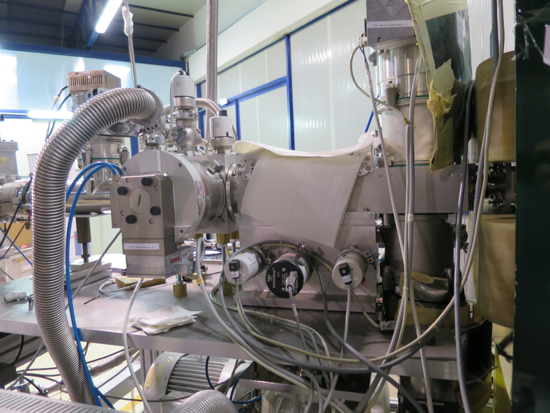
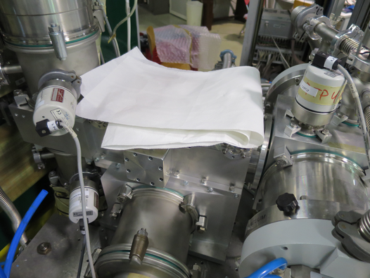
Performed general cleanup of lab. Boxed away cables and other parts. See attached pictures 1, 2, 3, and 4.
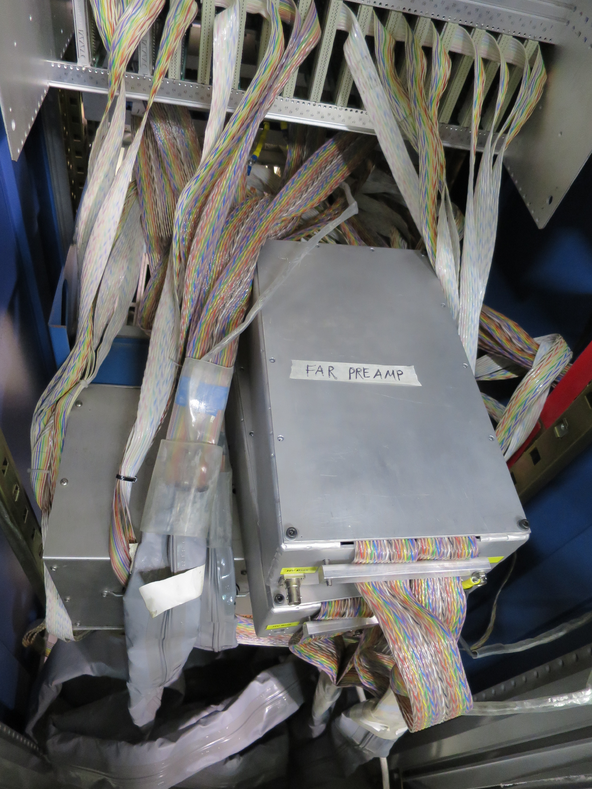
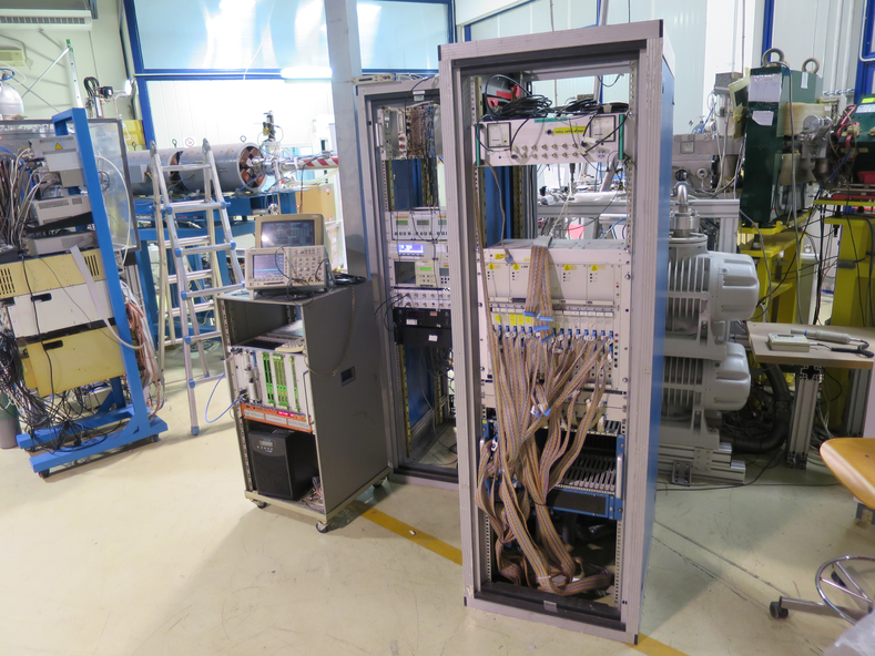
See attached picture 5, 6, 7, and 8 for status of electronics and target chamber at end of beamtime.
|
| Attachment 1: IMG_3381.JPG
|
|
| Attachment 2: IMG_3385.JPG
|
|
| Attachment 3: IMG_3383.JPG
|
|
| Attachment 4: IMG_3384.JPG
|
|
| Attachment 5: IMG_3386.JPG
|
|
| Attachment 6: IMG_3387.JPG
|
|
| Attachment 7: IMG_3388.JPG
|
|
| Attachment 8: IMG_3389.JPG
|
|
|
73
|
Mon Dec 3 19:04:20 2018 |
Thomas Chillery, Raffaele Buompane | End of beamtime - Items to be shipped back to Edinburgh |
To be shipped back to Edinburgh for repair:
|
Item
|
Quantity |
| ECL - NIM Convertor |
2 |
| Quad HV Supply |
1 |
| Quad TFA |
1 |
| SMC - SMC Cable |
1 |
| Central lid iris arm |
1 |
| Central lid - with iris |
1 |
| Diode mount |
1 |
| S2 2623-26 (505um) |
1 |
| PB-4 Pulser |
1 |
| BNC - SMC Bulkhead Connector (from close preamp box) |
1 |
| Lecroy 622 NIM module |
1 |
|
|
24
|
Wed Mar 7 16:56:52 2018 |
Thomas Chillery, Peter Black | Tests - Modifying Chamber Parts in Edinburgh |
Today we began examining and modifying parts of the chamber shipped from CIRCE to Edinburgh.
The parts shipped were:
- Chamber Collar
- Central Lid
- Downstream Lid
- Two Metal Detector Masks
- Two Iris Mounts
- One Iris
- Two Actuators
- Pin Diode Mount
This morning we began piecing parts of the chamber one by one, starting with putting the lids on the collar and checking how easily the iris arms fit. We found whilst fitting together the chamber that the actuator used to control the downstream iris will need to be moved further away from the chamber than the current Al tubes allow. This is because currently the aperture arm hits the metal iris mount. By moving the actuator further away there will still be space for a thin wire to hook onto the iris arm.
Originally the S2 detector was intended to be mounted with the front strips facing downstream. We found in CIRCE during the recent February shifts that this was not possible, because the connectors on the detector PCB hit the lid.
Today Peter machined space for the downstream detector connector, so now the detector may be mounted as originally intended. We checked the vacuum feedthrough still fits too.
However, the ribbon cable between detector and feedthrough will still come between the actuator arm and the iris arm, so adjustment of the iris from outside the chamber is still not possible. We are still working on this.
|
|
25
|
Tue Mar 27 16:36:01 2018 |
Thomas Chillery, Peter Black | Tests - Modifying Chamber Parts in Edinburgh |
Between 7th to 21st March modifications were made to the top of the CIRCE target chamber.
These modifications address the three key issues highlighted during the February shifts
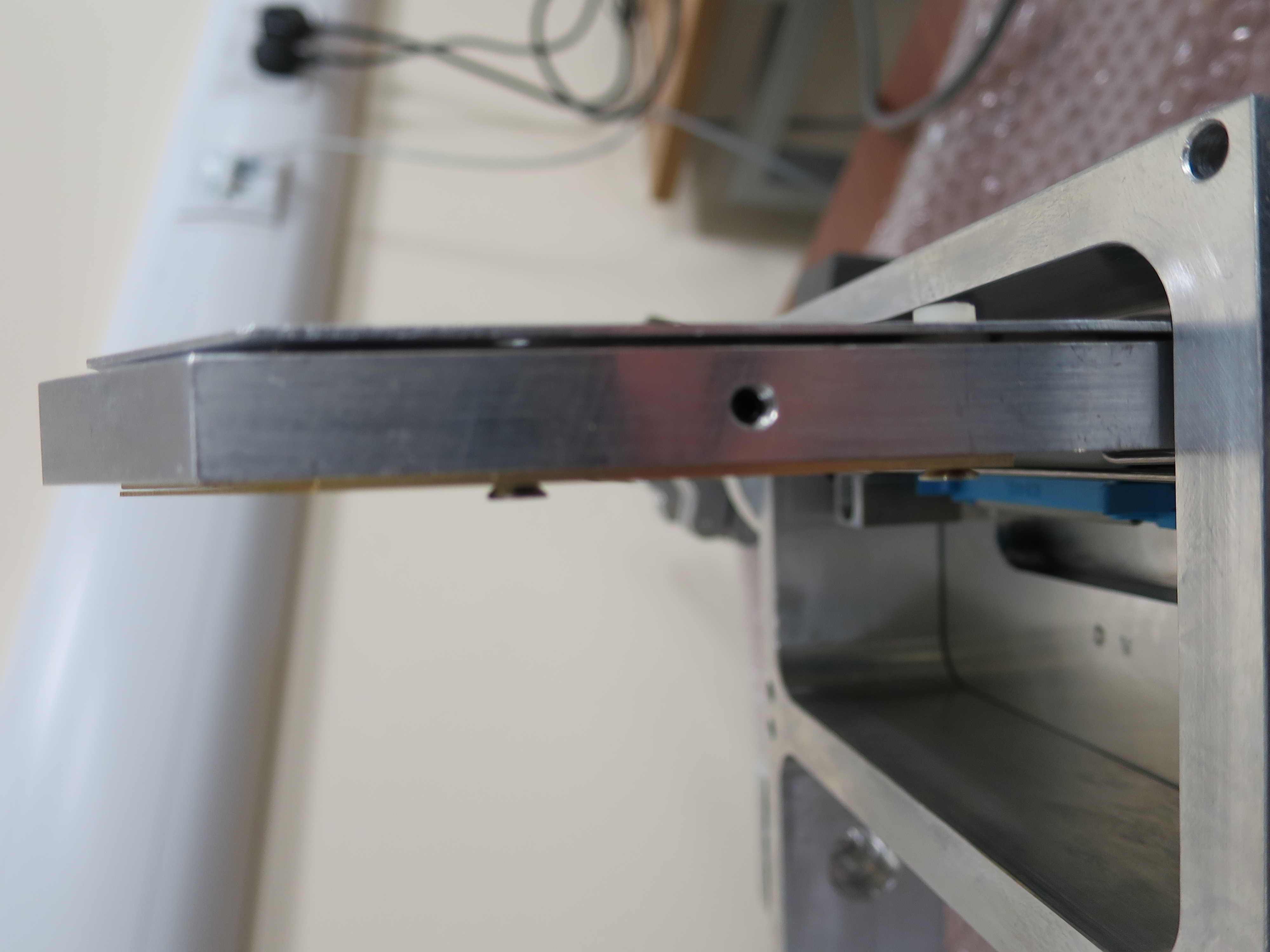
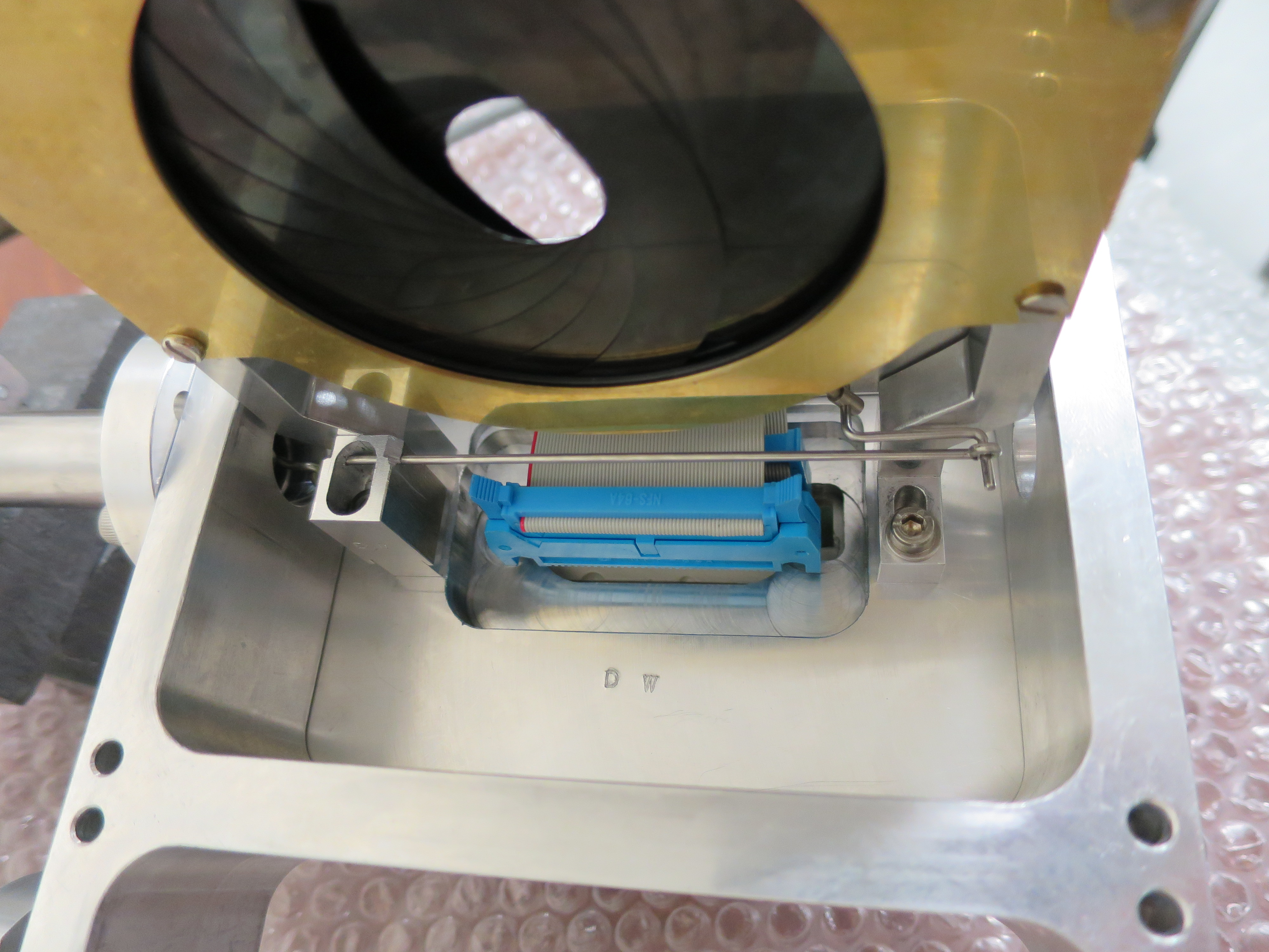
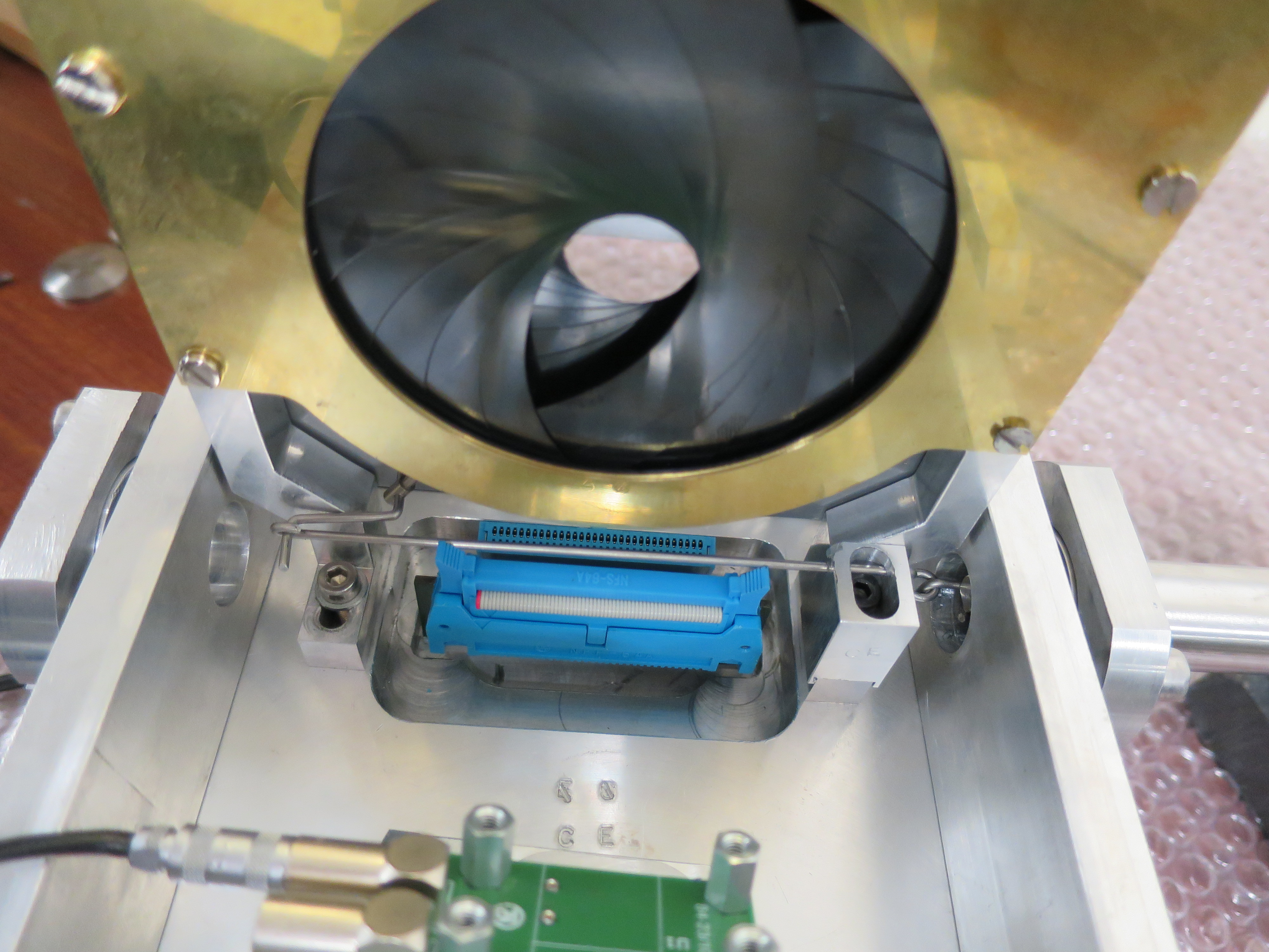
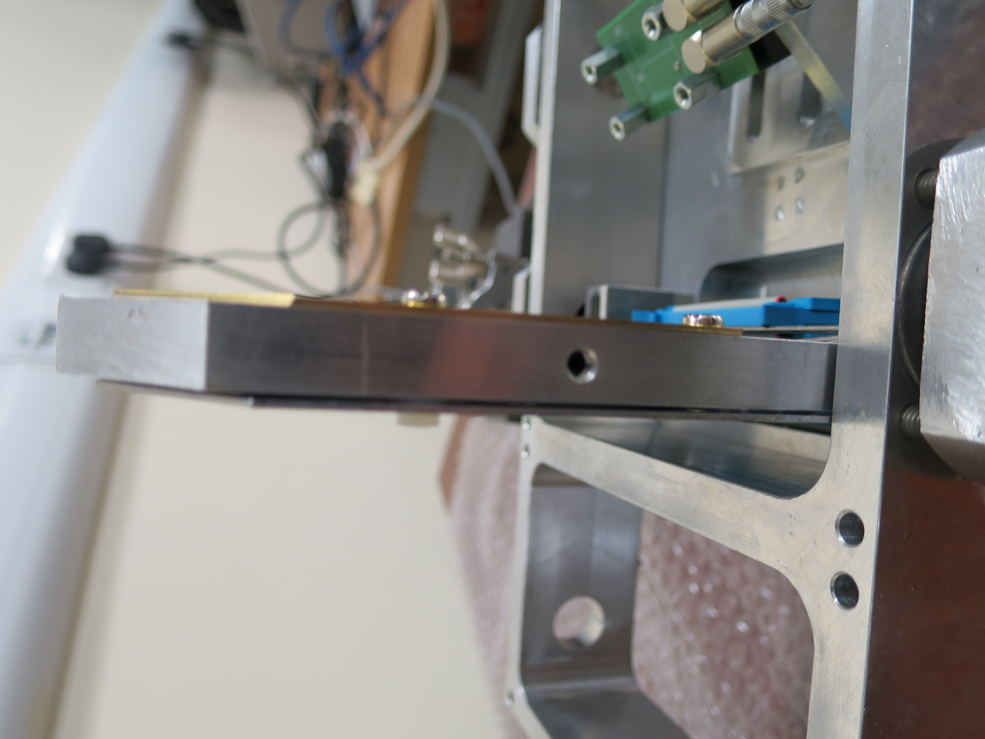
1. The central S2 detector did not fit, because its connector pins came into contact with the chamber lid
Additional machining was performed on the central chamber lid, allowing the pins to fit
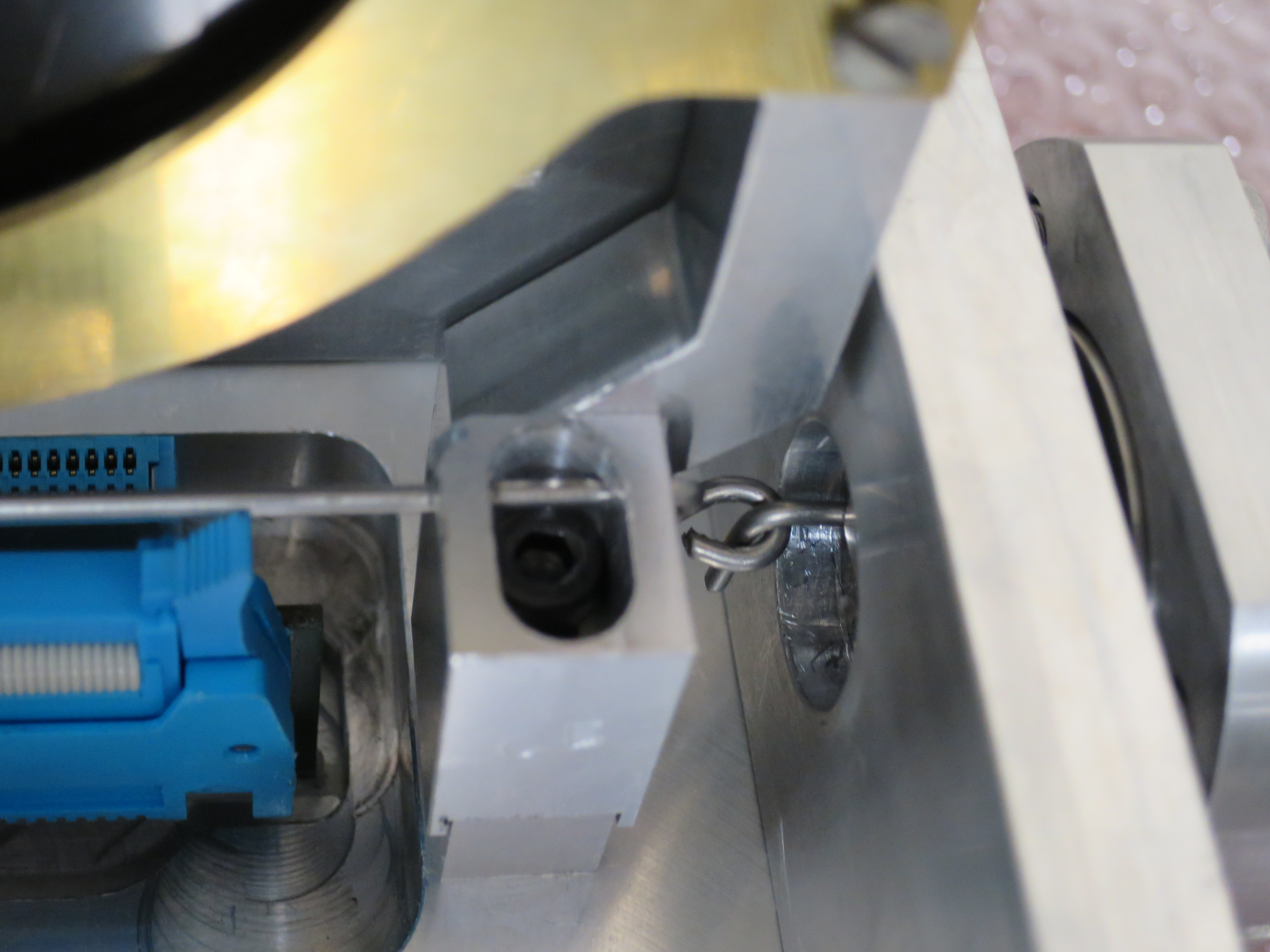
2. Mounting the iris hooks was non-trivial, resulting in the inability to open and close the irises whilst the lids were mounted on the chamber
Peter designed a guide rod allowing the hook to be connected to the iris arm before mounting the lid onto the chamber. Now the only difficult part is ensuring the actuator arms hook connects to this guide rod.
I checked the position settings needed for both actuators when mounting or removing the chamber lids, these are:
Central actuator setting = 85.5mm
Downstream actuator setting = 82.5mm
The actuator positions for a fully opened iris still need to be checked in CIRCE.
When mounting the lids the guide rods will be arranged such that the irises are in the mostly-closed position (~16mm diameter). This reduces chance of damage made to the S2's during installation and removal, and also means the iris is already setup ready for beam tuning.
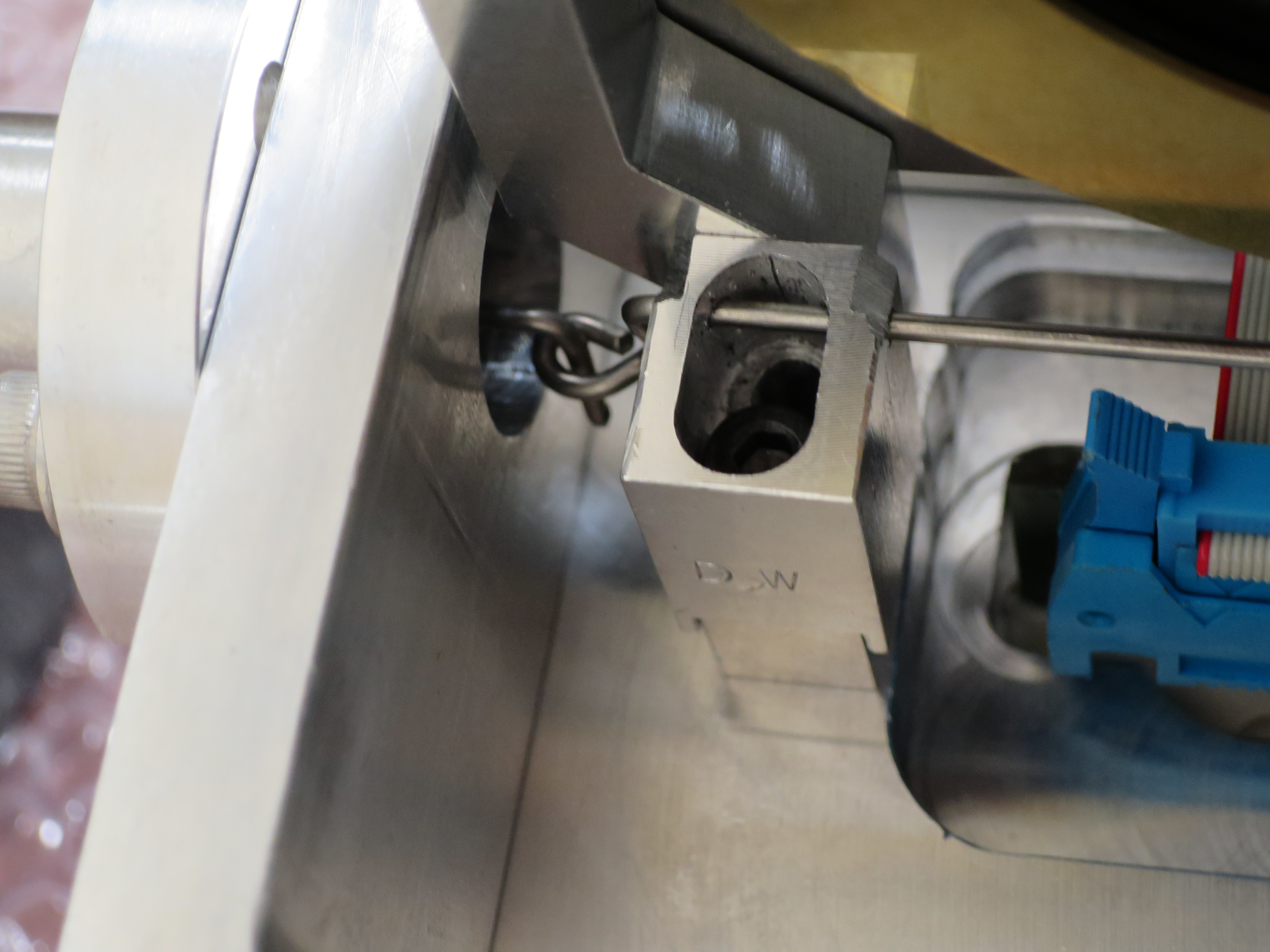
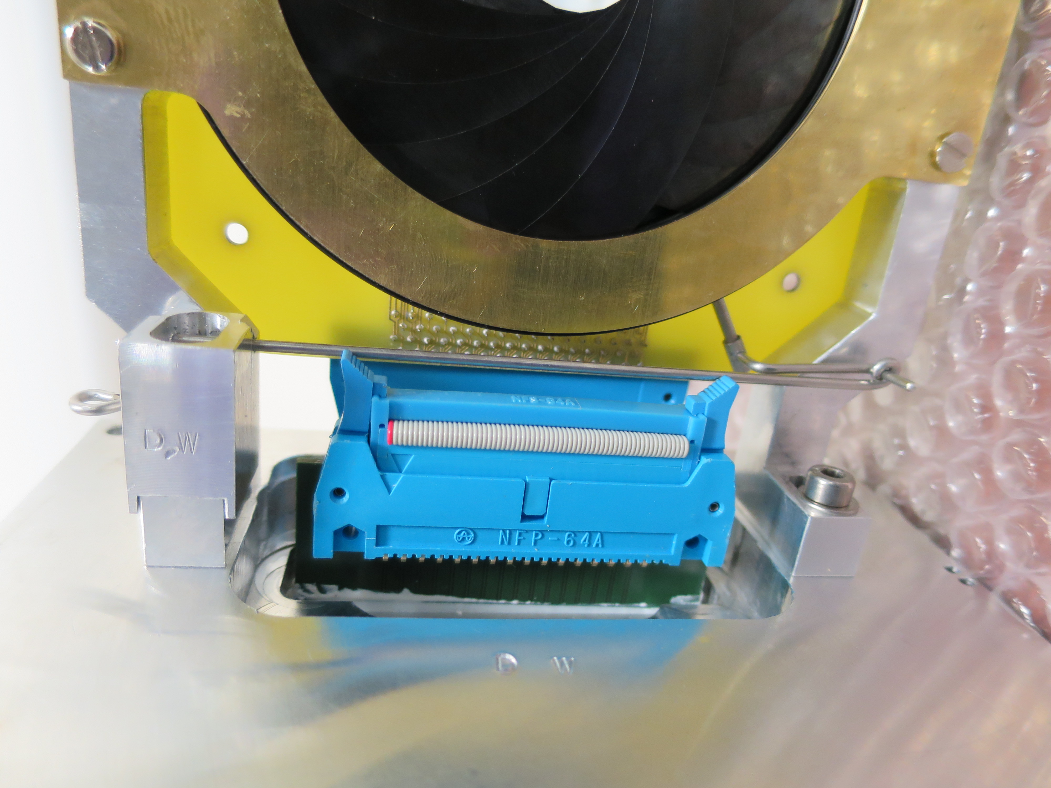
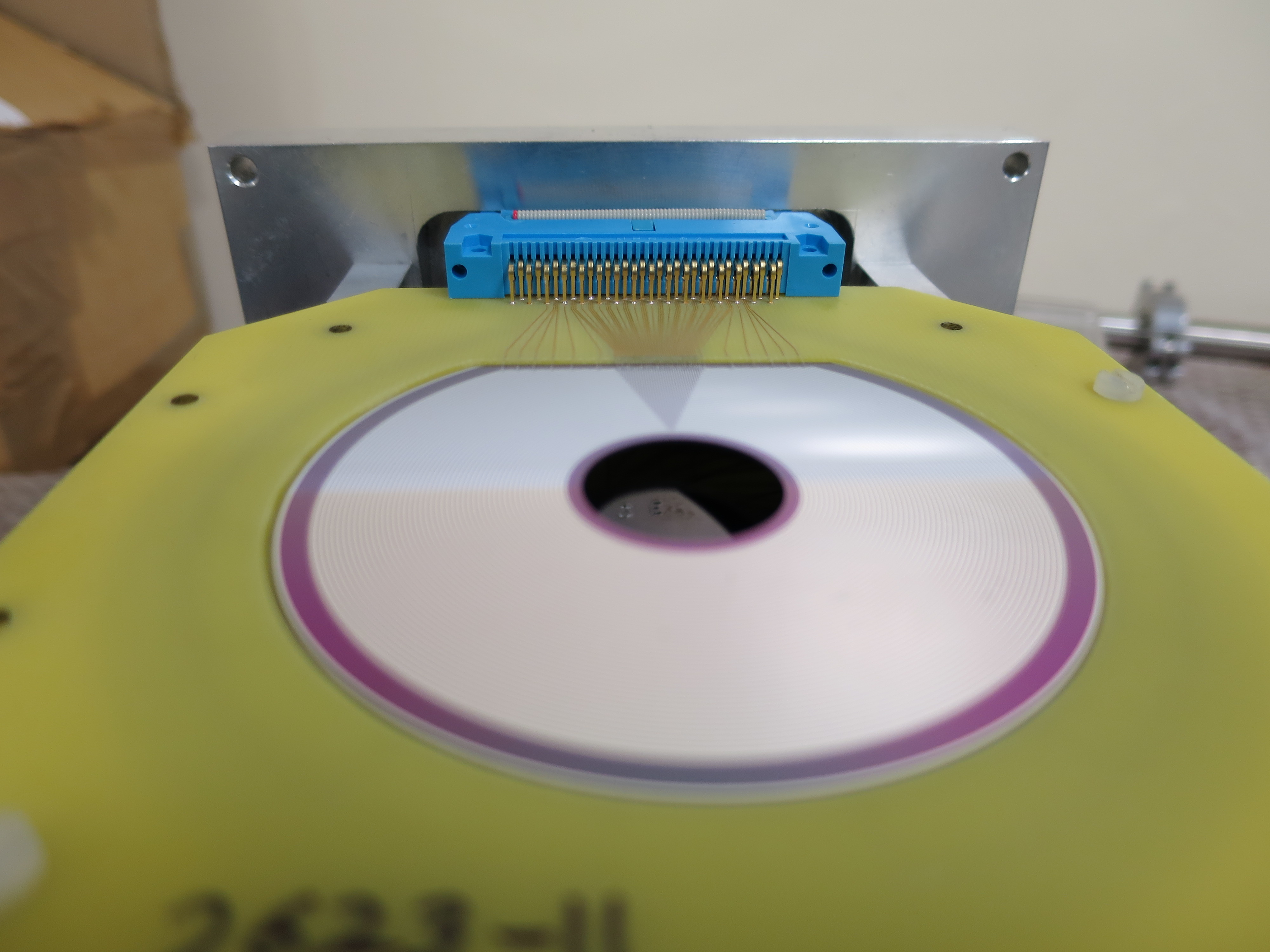
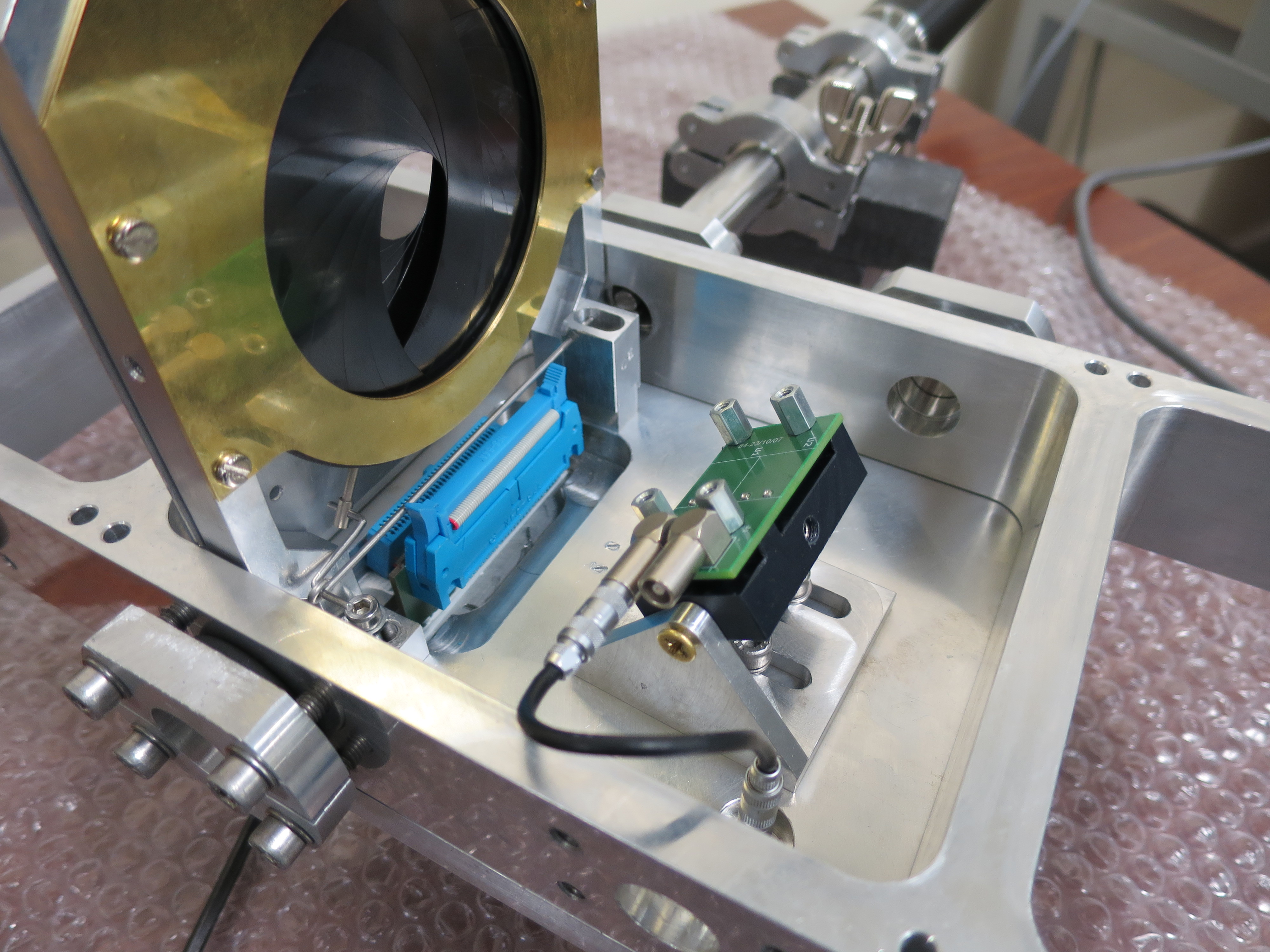
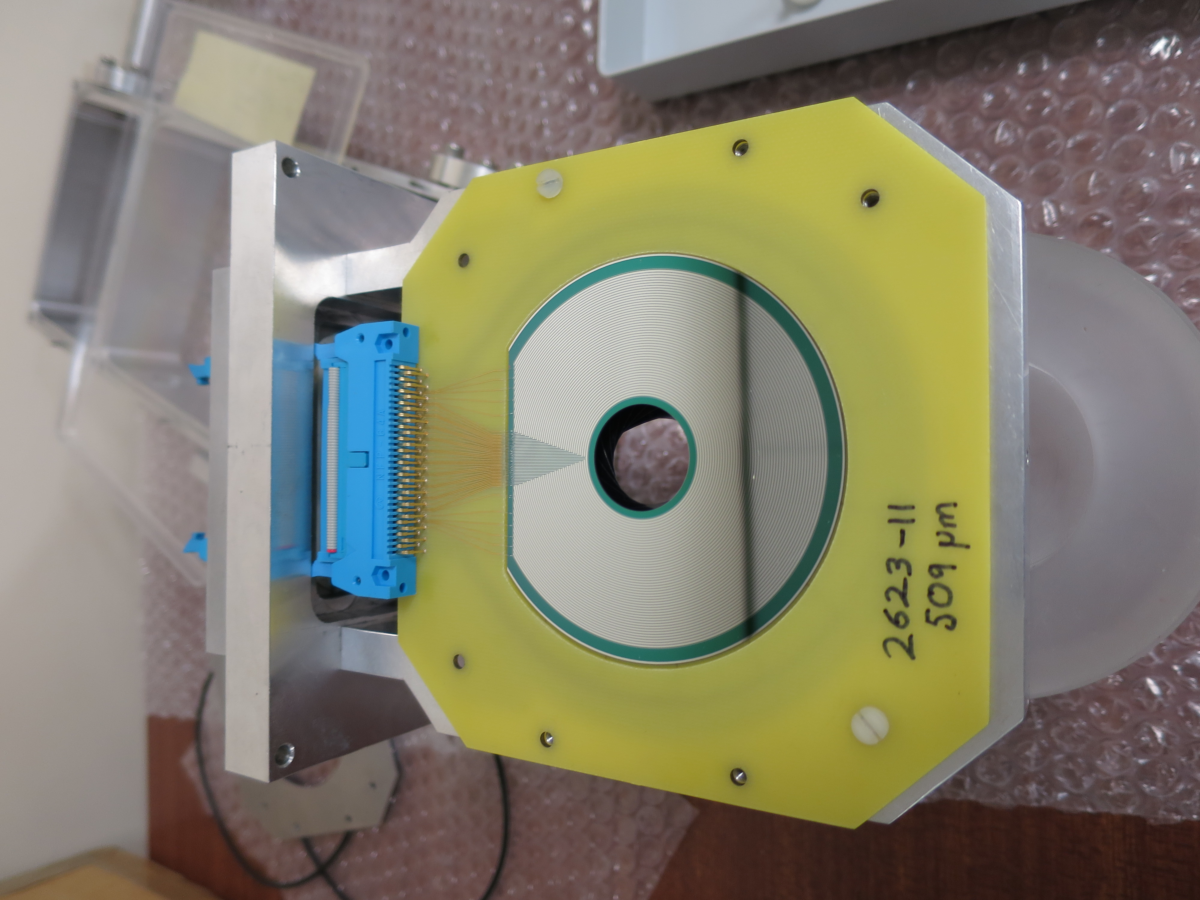
See attached pictures for the downstream and central lids.
A sample S2 in Edinburgh was used to check the connectors fit with the lid and other parts. When mounting the lids onto the chamber collar it was decided to leave the S2s off the iris mount. This was to avoid the risk of damaging the S2 from slippage of the parts - note in CIRCE the collar will be on top of the target section with threaded rods and so the conditions are more stable than on tabletop. During lid mounting, the metal mask was used in place of the S2 to simulate its size.
Marks "CE" and "DW" were made respectively on the central and downstream lids and guide rods.
3. The pin diode angle was not reproducible
A mounting block has been machined in Edinburgh, it has an angled slant of 39.0 +/- 0.5 degrees for setting the angle of the plastic block used to support the diode. We noticed in the CAD drawing that mounting the diode at the closest distance to the target would mean the target frame is likely to cause scatter from the backscattered beam, therefore we chose to mount the diode in its central position. The angled block has a width 22.0 +/- 0.1mm for setting the distance between the back of the diode mount and the upstream side of the central chamber lid.
An excel spreadsheet was used to calculate the diode angle, see attached "DIODE_ANGLE_CALCULATION.xlsx"
The chamber parts were shipped back to CIRCE and arrived on 26/03/18, the mounting block and PB-5 Pulse Generator were also sent in the same shipment.
|
| Attachment 1: DIODE_ANGLE_CALCULATION.xlsx
|
| Attachment 2: Downstream_1.JPG
|
|
| Attachment 3: Downstream_2.JPG
|
|
| Attachment 4: Downstream_3.JPG
|
|
| Attachment 5: Downstream_S2_1.JPG
|
|
| Attachment 6: Downstream_S2_2.JPG
|
|
| Attachment 7: Central_1.JPG
|
|
| Attachment 8: Central_2.JPG
|
|
| Attachment 9: Central_3.JPG
|
|
| Attachment 10: Central_4.JPG
|
|
| Attachment 11: Central_S2_1.JPG
|
|
|
43
|
Wed Nov 21 08:45:03 2018 |
Thomas Chillery, Marialuisa Aliotta, Raffaele Buompane, Carlo Bruno | Testing Chamber Vacuum |
On 19/11/2018:
We mounted the following in the chamber:
- Iris frames - no S2 detectors or mylar
- Si pin diode mount with 0.9um mylar - no diode
- Target ladder with blank frames - same configuration as elog entry #41
At 15:20 we started roughing pumps Ecodry 1 and 2. We opened the manual gate valve followed by the T1600 valve.
After reaching ~10^-2 mBar we started the following turbos:
- Up 1
- Up 2
- Down 1
- Down 2
- T1600
- Entrance 3
- CSSM
By 15:30 the CSSM turbo had reached 56 krpm operating speed and the Up and Down turbos had reached 833 Hz operating speed.
At 19:51 just before we left the lab the pressures read, in mBar:
- TPU1 = 3.7e-6
- TPU2 = 6.9e-7
- TPD1 = 1.0e-6
- TPD2 = 1.2e-6
- CHUP = 6.0e-6
- CHDW = 1.4e-5
|
|
42
|
Wed Nov 21 08:37:24 2018 |
Thomas Chillery, Marialuisa Aliotta, Raffaele Buompane | Upstream Collimator |
On 19/11/2018:
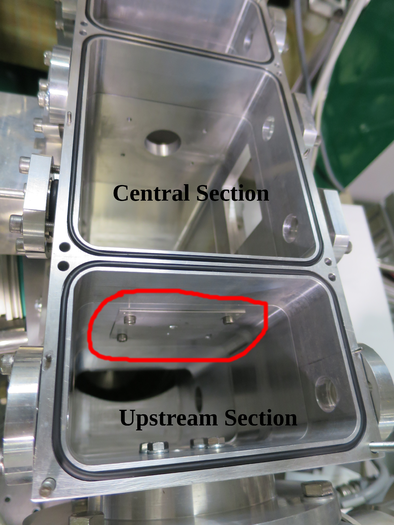
During the target ladder calibration (see elog entry #41) we also replaced the collimator (thickness ~24mm, diameter 3mm) located immediately upstream from the target ladder - that is between the upstream and central sections of the chamber. We mounted an aluminium collimator (thickness ~1mm, diameter 5mm). See attached picture 1.
Using the same telescopic sight as that used for the target ladder calibration, we aligned the 5mm collimator with the beam axis. |
| Attachment 1: IMG_3391_Modified.JPG
|
|
|
52
|
Sat Nov 24 16:29:10 2018 |
Thomas Chillery, Marialuisa Aliotta, Carlo Bruno, Tom Davinson, Raffaele Buompane | Preparing setup for 7Li beam |
On 23/11/2018:
10:15 started pumping down chamber with Ecodry 2
RAL thresholds:
- First 4 RALs = 10mV
- 5th RAL = 17mV
- 6th RAL = 20mV
- 7th and 8th RALs ECL disconnected
- 9th - 16th RALs not in use (no near S2)
10:30 pressures ~ 1mBar, opened T1600 backing valve, Turbos switched on
10:35 pressures (mBar):
- TPU1 = 5.2e-5
- TPU2 = 6.4e-6
- TPD1 = 6.0e-6
- TPD2 = 8.7e-6
- CHUP = 2.3e-5
- CHDW = 5.5e-5
Biased detectors: Far S2 bias = -130V, leak I = 1.54uA. Diode bias = -70V, leak I = 0.02uA.
Replaced diode TFA, now using channel 4 on new TFA. Diode connected to 3rd ADC channel 16 (counting from 0)
Started pulser only run
Closed far S2 iris (82.5mm actuator setting). Set target ladder to blank 10mm target frame.
Disconnected vacuum gauges located below chamber on same side as target ladder is mounted - noise improved
Started pulser only run
|
|
53
|
Sat Nov 24 16:39:22 2018 |
Thomas Chillery, Marialuisa Aliotta, Carlo Bruno, Tom Davinson, Raffaele Buompane | 7Li 4.0 MeV beam on CH2 target 15 |
On 23/11/2018:
Tuned beam for 4.0 MeV 7Li, charge state 2+
Measured transmission of beam through FCC using 3 mm and 10 mm size collimators: 66 pA with 10 mm -> 60 pA with 3 mm -> 91% transmission
FC4 = (330 - 263) pA = 127 pA
Set target ladder to position 3 - CH2 target 15 (880 +/- 40 ug/cm^2)
Start run
- Run # 181123130304
- Pulser: 70000 amplitude, x10 attenuation, 25Hz frequency (250Hz minimum fine setting), positive polarity
- Run time ~30 minutes
Start run
- Run # 181123134943
- Pulser: as above
- Run time 588 seconds
Moved to position #2 on target ladder, 10mm collimator. Increasing beam intensity -> have to refocus
Moved ladder to position #1 (3mm collimator). Closed iris. Refocusing.
Beam intensity after refocus: ~140pA with 10mm, ~90pA with 3mm. Trigger rate ~ 5500 counts/s
Moved ladder to position #3: CH2 target 15
Run # 181123142805
- Pulser: as above
- Run time: 1034
We found high rates on ADC 1 -> swapped input cables between ADC 1 and ADC 2 (modules #2 and #3)
Run # 181123144810
- Run time: 417
- Pulser: as above
Set RAL thresholds to 20mV for first 8 modules
Run # 181123150803
- Run time: 398
- Pulser: as above
Did not help with ADC 1 counting less than ADC 2. Swapping ADC 1 with ADC 4.
Run # 181123151711
- Run time: 324
- Pulser: as above
Swapping back ADC 4 -> ADC 1. Found ECL cable between the MALU module corresponding to ADC 1 and OR not plugged in. Trigger rate now 44000. Re-optimising noise.
RAL first 6 modules thresholds set to 30 mV. DT ~ 44%, high trigger rate.
First 3 RAL thresholds set to 35 mV, next 3 RAL thresholds set to 20 mV. Preamp box lid removed.
Run # 181123162236
Run # 181123163138
- Run time: 1561
- Pulser: ON, rate: 2.5 Hz, other settings unchanged
Run # 181123165817
- Run time: 3731
- Pulser as previous run
Run # 181123180118
- Run time: 1971
- Pulser ON, as before
Run # 181123183556
- Run time: 1638
- Pulser ON, as before
Checking beam intensity:
- Beam intensity = 197pA in FC4 at 18:34
- Beam intensity = 100 pA (91->105 pA) in FCC at 19:00
Run # 181123191153
- Run time: 7029
- Pulser ON, as before
Checking beam intensity:
- Beam current = 167 pA in FC4 at 21:00
- Beam current = 83 pA in FCC at 21:00
Lowering RAL thresholds:
- RAL #1 and 2 thresholds set to 25mV
- RAL #3 threshold set to 20mV
- RAL #4, 5, and 6 thresholds unchanged at 20mV
Now trigger rate ~ 5kHz, dead time ~ 8 - 10%
Run # 181123212726
- Run time: 807
- Pulser ON, as before
- Target: CH2 XV
- RAL #3 threshold increased to 25mV during this run
After previous run (# 181123212726) pulser frequency setting set to 25Hz, other settings unchanged |
|
54
|
Mon Nov 26 17:10:13 2018 |
Thomas Chillery, Marialuisa Aliotta, Carlo Bruno, Tom Davinson, Raffaele Buompane | 7Li 4.0 MeV beam on natC target 3 |
On 23/11/2018:
After the runs with 7Li on CH2 15, we moved the target ladder to position 5: carbon foil #3 (~590 ug/cm^2)
Run # 181123214406
- Run time: 1247
- Pulser ON, same settings as run # 181123130304
Beam intensity = 150pA on FCC with 3mm aperture
For the night we closed the quadrupole and line valves, and switched off the pumps and detectors. |
|
51
|
Sat Nov 24 15:07:00 2018 |
Thomas Chillery, Marialuisa Aliotta, Carlo Bruno, Lizeth Morales, Tom Davinson | Searching for causes of noise |
On 22/11/2018 in the afternoon:
We increased the ADC thresholds to 40 (previously 8).
For an alpha source with pulser connected, the event multiplicity dropped from ~63 to ~10. Dead time ~ 7%
Checking the timing signals for the near S2:
- RAL X channels 0 - 5 bad, 6 and 7 good -> disconnected timing
- RAL U, XII, XIII, R, and S good
- RAL W channels 0 - 5 good, 6 and 7 bad
- RAL Q all bad -> disconnected timing
Started alpha source run with pulser (same pulser settings as run before)
After run the Far S2 RAL thresholds set to 10mV, the close S2 thresholds set to 50mV
Started alpha source run, no pulser
Stopped run due to poor alpha rate -> ECL-Nim ribbon cable disconnected.
Checking bias:
- Far S2 bias = -130V, leak I = 1.91uA
- Close S2 bias = -129.9V, leak I = 13.11uA
- diode bias = -70V, leak I = 0uA
Vented chamber and checked 12um mylar foil in front of close S2 - no visual damage. LEft
Close detector changed: S2 2623-26 (505um) replaced with S2 2623-18 (508um). Mounted new S2 in close position with 12um mylar
Removed alpha source - needed by other experiment. Otherwise target ladder configuration is same as eLog entry #47
Checked grounding cables going from preamps to ICU boxes were tightly connected
Attempted to bias close S2 -> no leak current! Left lab for the day.
The next morning (23/11/2018):
We found the BNC - SMC bulkhead connector attached to the near S2 preamp box is missing a pin. We dismounted the near S2.
We observed ~50kHz noise on Far S2, this is removed when we lifted the preamp - ICU box ribbon cables away from the chamber vacuum gauges. |
|
45
|
Wed Nov 21 09:09:41 2018 |
Thomas Chillery, Marialuisa Aliotta, Carlo Bruno, Lizeth Morales, David Rapagni | Mounting Detectors / Continuing Electronic Chain Tests |
On 20/11/2018:
At 9:00 we walked into the lab, David R reported he found all the pumps OFF. A thunderstorm occurred overnight causing a power outage.
Last night we had switched off the electronics (Preamp power, RAL amp rack, and NIM bin).
This morning we determined everything was ok to switch on.
Using eLog entries #26 and #27 as reference we mounted the following detectors and foils:
- Far S2: 2323-18, 12um mylar
- Near S2: 2623-26, 12um mylar
- Silicon pin diode: 0.9um mylar
The pin diode used in previous tests had something deposited (fingerprint?) on the crystal, so we replaced this with a new clean diode.
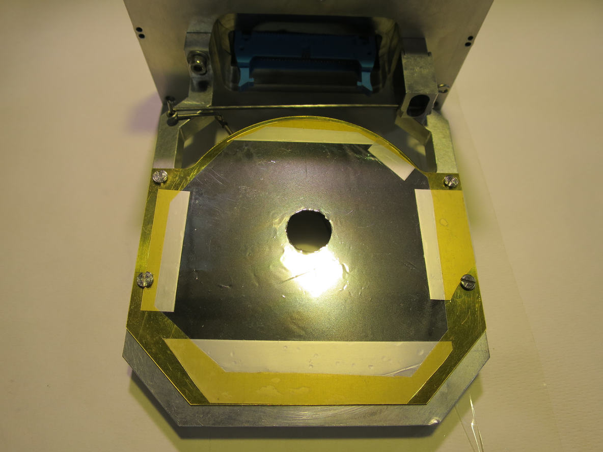
We mounted the detectors and foils inside the chamber, the target ladder was kept in its configuration with all blank frames (see eLog entry # 41). See attached picture 1 for the 12um mylar mounted in front of the far S2.
We mounted preamp I on the near position and preamp II on the far position, as will be used during the measurement.
We sealed the chamber to ensure it was light tight.
We applied pramp power, expected currents were drawn.
With no S2 bias we see high noise on the majority of the RAL amplifiers for both preamps I and II. We switched off the lab lighting and found the chamber was indeed light tight - there were no observable changes in noise.
We discovered CH2 of the Silena HV module does not supply bias.
We applied -10V bias to both S2's. The far S2 is biased using CH1 and the near S2 is biased using CH4 of the HV module. The leakage currents read: Far S2 = 0.35uA, Near S2 = 1.81uA.
With bias RAL X CH 0 baseline RMS noise ~ 55mV.
We biased the pin diode with its operating -70V using CH3 of the HV module, leak I = 0.01uA.
We decided to switch off all biases and prepare for tests under vacuum with an alpha source.
CH1 and 4 of the HV module were set to -130V ready for the S2's
|
| Attachment 1: IMG_3209.JPG
|
|
|
44
|
Wed Nov 21 08:53:06 2018 |
Thomas Chillery, Marialuisa Aliotta, Carlo Bruno, Lizeth Morales | Testing Electronic Chain - No Detectors |
On 19/11/2018:
During the vacuum test - see eLog entry #43 we performed noise tests on the preamplifiers with no S2 detector connected
First we performed a "tabletop" test - the preamplifiers were not connected to the chamber.
Preamp I for the near S2 is connected to RAL modules (reading left to right): X, XII, XIII, R, S, Q, U, and W, via long (~5m) preamp - ICU cables 13, 14, 15, and 16
Preamp II for the far S2 is connected to RAL modules (reading left to right): I, II, XI, IV, V, VI, VII, VIII, via long (~5m) preamp - ICU cables 0, 1, 2, and 3
We powered preamps I and II with + and - 15V. The power supply shows the correct currents drawn: ~1.5A for +ve and ~0.75A for -ve
We found our test 16 pin cables #45 had a dead channel 0, we switched to cable #46 which shows all 8 channels working.
We found the following dead channels on the RAL modules:
| RAL |
CH # |
| U |
0 |
| W |
0, 7 |
| I |
0, 5 (Both disabled in ICU) |
| II |
0, 2
|
We mounted preamps I and II to the top of the chamber. We mounted preamp I on the far S2 mount and preamp II on the near S2 mount, however we were not connecting to the S2's and so continued with the electronics tests.
Now we saw the following dead channels on the RAL modules:
| RAL |
CH # |
| W |
7 |
| I |
0, 5 (disabled in ICU) |
| II |
0, 2 |
We checked the signal to noise ratio for RAL X CH0:
The input pulser amplitude = 50mV, the RAL analogue amplitude = 950 mV, the RMS noise = 40mV. The S/N ~4.2%.
We stopped tests for the day. |
|
46
|
Wed Nov 21 09:28:06 2018 |
Thomas Chillery, Marialuisa Aliotta, Carlo Bruno, Lizeth Morales | Problem encountered with near iris arm |
On 20/11/2018:
After the electronics tests in air (see eLog entry #44) we started to setup the chamber for vacuum tests with an alpha source.
We started mounting the aperture used for controlling the near iris arm, however we encountered a problem. The iris arm got stuck and could not move in either direction (into or out of the chamber)
We dismounted both preamps. After bending the near iris arm's hook we managed to dismount the chambers central lid.
Before doing anything else, we dismounted the near S2 and 12um mylar foil.
A new iris arm for the near iris needs to be manufactured by the workshop in CIRCE. The workshop was closed for the end of the day, so we also stopped for the day. |
|
48
|
Thu Nov 22 11:34:07 2018 |
Thomas Chillery, Marialuisa Aliotta, Carlo Bruno, Lizeth Morales | Continuing Electronic Chain Tests |
This morning at 8:35am the pressures read (in mBar):
- TPU1 = 2.0e-6
- TPU2 = 4.5e-7
- TPD1 = 8.1e-7
- TPD2 = 7.9e-7
- CHUP = 4.7e-7
- CHDW = 1.1e-5
The detectors were biased. Far S2 leak I = 1.54uA, near S2 leak I = 12.53uA.
It was discovered the ECL-NIM-ECL converter located immediately to the left of the pulser has broken channels - the last 8 channels. Instead of connecting the 32 pin ribbon cable to the input and taking lemo outputs 5 and 13, we are now connecting two single channel pin cables to inputs 1 and 2, and taking the corresponding lemo outputs.
We found RAL X sometimes doesn't produce a trigger for the pulser.
We replaced RAL I with RAL XIV, RAL XIV is bad.
We replaced RAL XIV with RAL XV, RAL XV is good.
We finished setting the RAL thresholds. |
|
49
|
Thu Nov 22 11:53:08 2018 |
Thomas Chillery, Marialuisa Aliotta, Carlo Bruno, Lizeth Morales | DAQ tests with alpha source |
The target ladder is set for position 7 - the double alpha source.
Looking at the FAIR DAQ, for the Far S2 the first RAL amplifier (XV) shows:
- Alphas at channel 700
- Pulser centroid at channel ~2640, with 9 channel FWHM -> corresponds to 44 keV FWHM at 4.91 keV/channel
The close S2 shows:
- Alphas at channel 700
- Same pulser centroid as far S2, with 6 channel FWHM -> corrsponds to 24 keV FWHM at 4.91 keV/channel
We reenabled the top ICU box channels 0 and 5 (disabled during Feb 2018 shift)
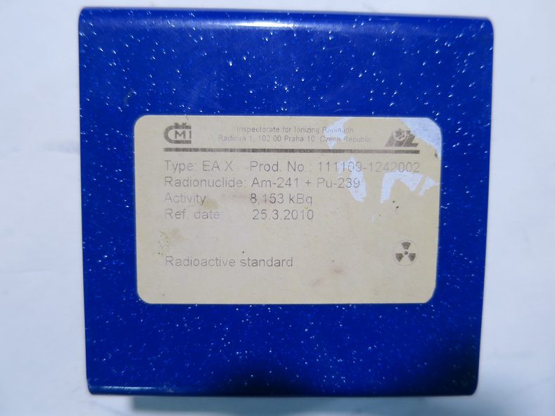
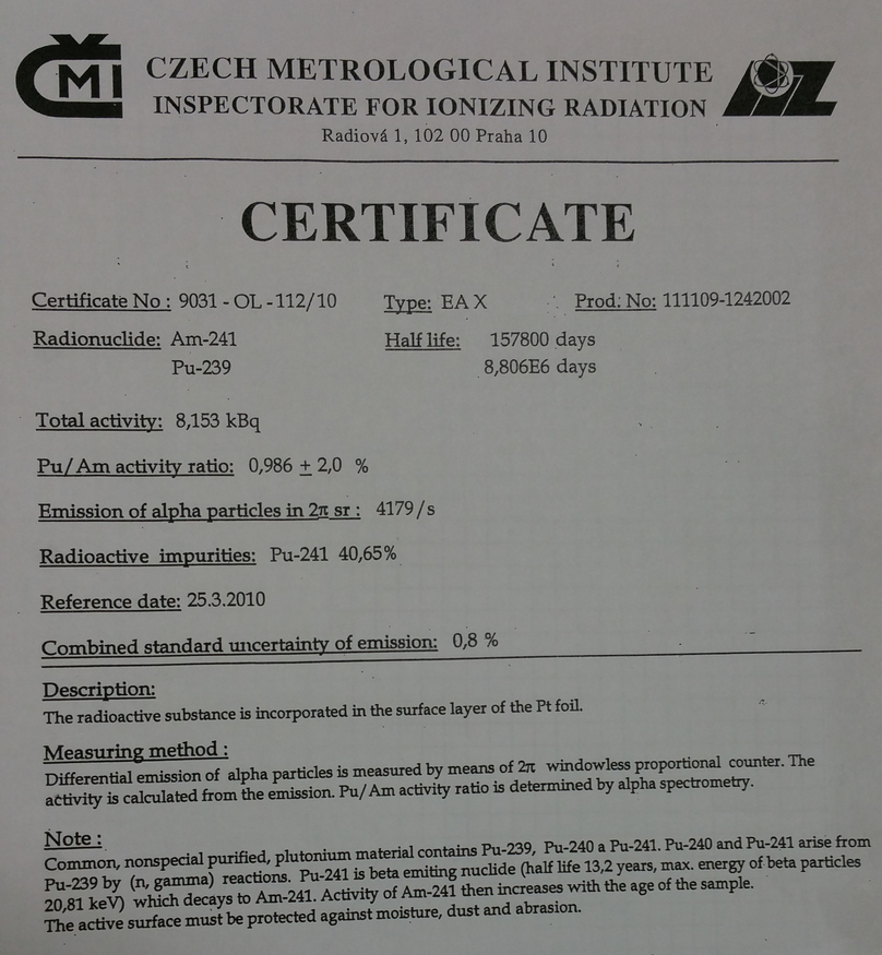
We started an alpha-source run using the 241Am and 239Pu source, type: EA X, product number: 111109-1242002. Photo of source storage case is attached.
Alpha activity at 25/03/2010: 8.153 kBq
We found the following strange behaviour
With DAQ list mode OFF:
- Trigger rate ~2300 - 2700/s
- Event mult ~ 140
- DT~18%
With DAQ list mode ON:
- Trigger rate ~300 - 900/s
- Event mult ~140
- DT ~ 70 - 90%
Currently ADC 2, 3, 4, and 5 are in use by the far and near S2's. ADC 6 and TDC 7 are not currently in use (we will need ADC 6 for the pin diode)
We set the lower threshold for ADC6 and TDC7 to 2046 out of 2047 channels - effectively disabling the two.
Now with list mode ON:
- Trigger rate ~ 1500 - 1700 /s
- Event mult ~ 65 - 70
- DT ~ 30 - 50 %
We restarted the DAQ machine
We started an alpha source run:
- Run number: 181122123034
- DT ~ 7 - 19%
- Trigger rate ~ 700 - 1000/s
- Event mult ~ 63
The PB-4 Pulser Settings are:
- Frequency: 250 Hz
- Delay: 1 us
- Rise Time: 0.1 us
- Fall Time: 100 us
- Reference: INT
- Polarity: +ve
- Amplitude on scope: 260mV
- Attenuation: X10 (X10 switch up, X2, X5, and the other X10 switch are down)
|
| Attachment 1: IMG_3329.JPG
|
|
| Attachment 2: AlphaSourceCertificate.jpg
|
|
|
50
|
Sat Nov 24 15:05:40 2018 |
Thomas Chillery, Marialuisa Aliotta, Carlo Bruno, Lizeth Morales | FAIR DAQ |
The FAIR DAQ IP address: 192.168.1.90
The data is saved in /Local_Parts/Part0DE/
After each run we should copy the data to the 7Be shift folder: /home/circe/7Be_pp/181122/
We convert the data to a .root file via the command: fair2root ./run#
To convert the data to root we need to use the fairdef.in config file |