| ID |
Date |
Author |
Subject |
|
44
|
Tue Nov 7 14:38:25 2017 |
Ruchi Garg | Target ladder configuration | |
| Attachment 1: TargetLadder.pdf
|

|
|
43
|
Mon Nov 6 16:12:47 2017 |
Peter Black | chamber drawings | work in progress. |
| Attachment 1: FullAssemb2.PDF
|

|
| Attachment 2: section.PDF
|

|
|
41
|
Mon Nov 6 10:52:58 2017 |
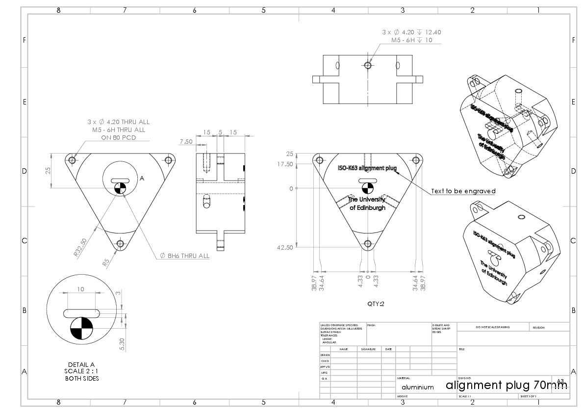
Peter Black | alignment hardware drawings | |
| Attachment 1: ladder_alignment_block.PDF
|

|
| Attachment 2: S2_alignment_bar.PDF
|

|
| Attachment 3: alignment_plug_70mm.PDF
|
|
| Attachment 4: alignment_plug.PDF
|

|
|
40
|
Mon Nov 6 10:50:33 2017 |
Peter Black | foil mount drawings | |
| Attachment 1: SiPD_foil_mount.PDF
|

|
| Attachment 2: fOIL_HOLDER.PDF
|

|
|
39
|
Mon Nov 6 10:46:53 2017 |
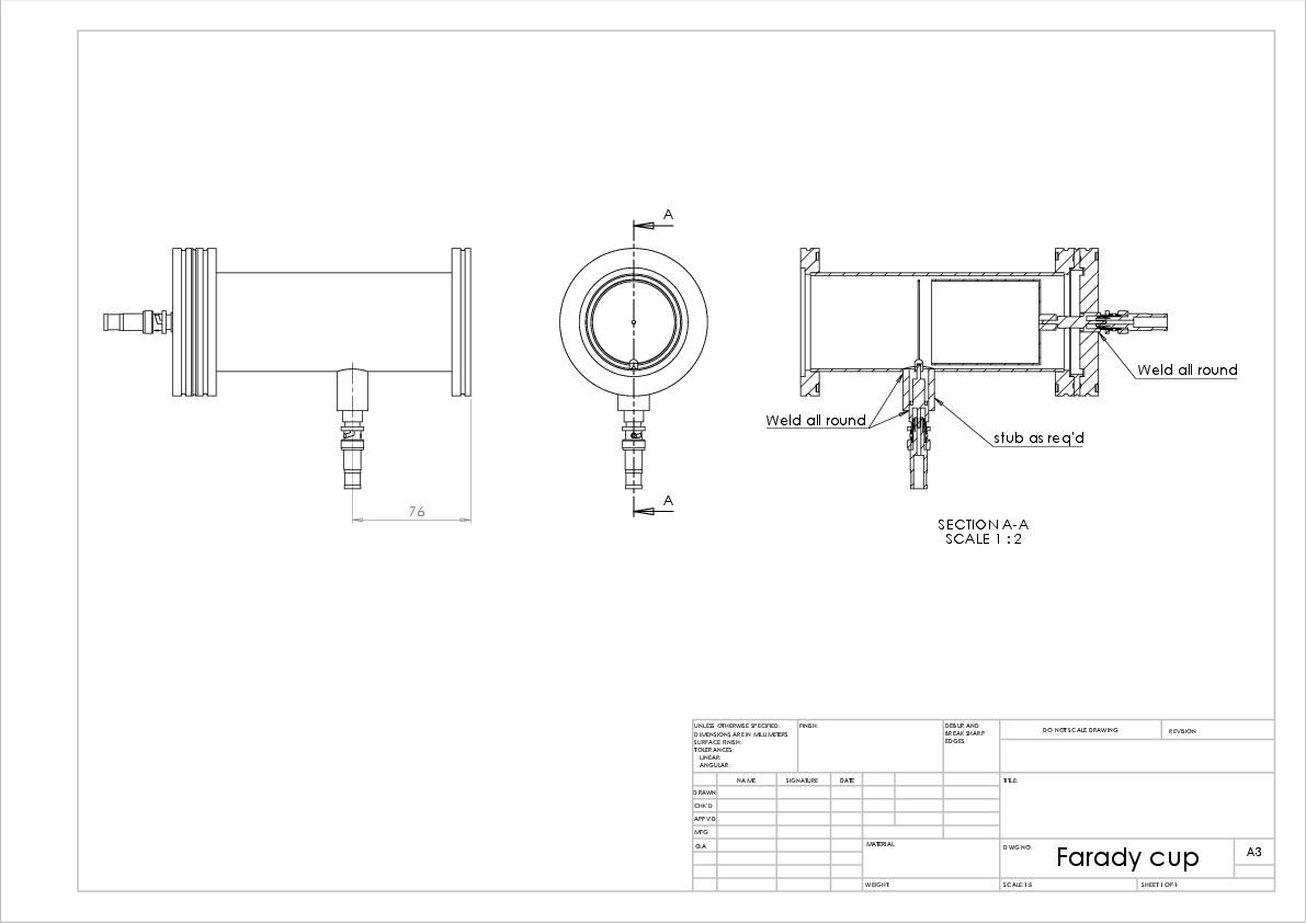
Peter Black | Faraday cup drawings | Note that the removal of the supressor reqires the special allen key. |
| Attachment 1: Farady_cup.PDF
|

|
| Attachment 2: cup.PDF
|

|
| Attachment 3: supressor.PDF
|

|
| Attachment 4: Farady_cup_main.PDF
|
|
|
38
|
Sun Nov 5 20:25:10 2017 |
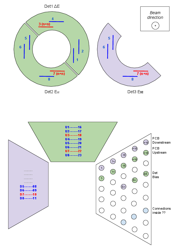
Ruchi | Circuit diagram and cable mapping | |
| Attachment 1: Cabling.pdf
|

|
| Attachment 2: PreampsPCBs.pdf
|
|
| Attachment 3: Circuit.pdf
|

|
|
37
|
Sat Nov 4 14:10:20 2017 |
daid | Julabo chiller operation | This log entry contains a basic instruction on how to operate the Julabo liquid flow chiller.
There are 5 buttons (left to right): Up/Down, Enter, 1/0.
To toggle power to the device, use 1/0 (on/off). NB: This only turns the electronics on, and does not initiate circulation / cooling.
When switched on, it will display sequentially some basic information sequentially. One may generally ignore these, and wait until it displays the current temperature.
To adjust or check the set point, tap either of Up/Down. To change the set point, press and hold either up or down. Release the button when the desired set point is reached,
and tap up/down to do the fine tuning.
Once the desired set point is entered, the display will return to the current temperature reading.
To turn on circulation / chilling, press and hold Enter (the down/left facing arrow). One needs to hold this button several seconds. It is obvious when it begins to operate, as
it will make more sounds, and additionally the Snowflake LED indicator should turn on (unless the current temperature is lower than the set point, it may simply flash briefly).
The set point can be adjusted while the circulation / chilling is on, as above.
To turn the circulation / chilling off, hold down Enter again for several seconds.
Best to raise the set point to ~20 degrees and wait for it to reach the value, before turning off circulation, and finally the device (0 button). |
|
36
|
Sat Nov 4 06:29:03 2017 |
TD | MIDASsort online sort programs, spectrum titles, calibration s/w & READMEs | |
| Attachment 1: IS607.tar.gz
|
| Attachment 2: Calibration.tar.gz
|
| Attachment 3: READMEs.tar.gz
|
|
35
|
Mon Oct 30 09:46:04 2017 |
Peter Black | Notes on iris install/operation | The iris mounts have 2 superimposed constellations of 3mm mounting holes on them that correspond to those of the S2 detector, however the 85x85 square is missing one hole and the 110x40 rectangle is rotated by 45°. Either constellation may be used. Fixing is intended with M3x16 bolts into 10mm standoffs used to attach the detector to its mount.
Electrical connection is by a 5 pin DuPont connector. A feedthrough with flying tail ribbon cable inside and M12 5 pin A-coded industrial sensor connector outside for each iris is supplied that should fin in the same flange as the cooling pipes. The connection between the ribbon and the actuator is to be made with the red coded wire on the ribbon to the yellow wire on the actuator such that the visible metallic portion on the pins is visible on the same side of both the male and female connectors when matted.
The control box needs to be mounted outside the chamber and the cables connected to the feedthroughs.
Power is supplied from the 12v PSU provided.
Twiddle knob to make iris open and close...
Notes:
- When handling the irises it is advisable to leave them in the open position.
- Don’t get grease on the irises or they will jam up and the actuator is strong enough to destroy them.
- The actuators contain a small quantity of grease, if this turns out to be an issue with the vacuum I will strip them down and degrease them.
- The controllers are “tuned” to the actuators so try not to muddle them up. (U and D)
- When not in use I would suggest removing power from them as they will potentially radiate some RF noise and just made your signals noisier.
- Datasheet for controller https://s3.amazonaws.com/actuonix/Actuonix+LAC+Datasheet.pdf
- They have been roughly set so that closed is a 20mmm orifice. If you need to adjust them open the control box and twiddle the pot next to the one next to the USB port (P2 right if you look at the data sheet). Cycle the power and to open and close it again, repeat until the desired orifice is achieved.
- Pins 1, 4 and 5 of X2 are the feedback potentiometer for the actuators so if you want to know where the actuators are (you think they may have jammed etc.) you can simply measure the voltage between 1 and 4 with the power on or the resistance with the power off
|
|
34
|
Tue Oct 24 09:27:24 2017 |
Peter Black, DK | Safety words | 
Plate 1. Contents of chamber

Plate 2. not ideal, but shows some of the scattering chamber and support stand
Better picture would have:
1) Wheels with feet
2) Chamber closed up
3) Not a bunch of junk from unpacking
Chamber system needs some kind of name for the documentation.
Overview
The Edinburgh Scattering Chamber is designed for charged-particle induced reaction cross section measurements of astrophysical interest.
One of its main features is radial symmetry, compatible with the TRIUMF UK Detector Array (TUDA) which mainly uses the Micron S2-type silicon strip detectors (SSDs) placed downstream of the target.
The geometric similarity between the two setups allows the employment of similar hardware such as preamplifier PCBs, cooling plates, etc.
The arrangement allows for a large solid-angle coverage for light-ion detection (> 50% of 4-pi in the centre-of-mass frame), light ion particle identification by the deltaE-E method.
At present, our interests are aimed at neutron-deficient, medium-mass beams.
In this case and with the use of a thin target, beam-like recoils can also be detected further downstream by an additional S2 detector in coincidence with light ions with a typical efficiency >25% (depending on the precise geometry).
An adjustable target slider can hold up to ten targets (generally thin-film samples like CH_2, collimators, beam diagnostic devices ...), and we have plans to accommodate a windowed gas cell in the future to serve as a helium target. A CMOS pinhole camera is also provided to allow viewing of targets which will mainly be used in conjunction with a ZnS screen for beam tuning.
The end of the chamber is equipped with a detachable Faraday cup to assist with beam tuning and monitoring the beam intensity during experimental runs (depending on the radioactive beam intensity).
Chamber Design
The chamber is welded aluminium construction in the form of 2 barrels connected coaxially with flanges on each end. The barrels and flanges are secured with M14 bolts and sealed with ISO 400 centring O-rings.
The chamber is designed to be connected to the downstream port of the existing Scattering Chamber Experiments (SEC) installed at HIE-ISOLDE beam line XT03 by a KF50 port on the upstream end of the chamber. This connection has a turbo pump mounted on it to ensure that the vacuum exposed to the downstream systems is as low as possible. Further additions to the connection are a constrained bellow to take up any misalignment, an electrical break to prevent ground loops and a gate vale to allow the chamber to be opened without exposing the beam line to atmosphere.
All of this enables us to shoot through the SEC and have a minimal impact on other existing experimental setups.
The chamber is cylindrical and can be opened on the downstream side by sliding the end flange in the beam direction.
The end flange is mounted perpendicular to a sliding support structure, so that the chamber can be opened and serviced without the use of an overhead crane nor any requirements of heavy lifting.
Internally, the majority of the equipment is mounted on four rods installed on the inside of the end flange, which extend the full length of the chamber when sealed are supported by complimentary receiving sockets on the inner side of the upstream chamber end flange.
The chamber and its associated equipment (chiller, electronics racks) are fitted with wheels for easy positioning, enabling the chamber to be connected and disconnected from the XT03 beamline with relative ease.
The support structure is more than twice as long as the chamber itself, so that the chamber can be fully opened and easily serviced. This results in the chamber being stable in in the fore/aft direction but due to the height of the beam line and a preference for a small footprint the top heavy nature of the chamber and support it is potentially unstable in the side to side direction. To alleviate this outriggers are installed on the bottom of the upstream and downstream structure with retractable wheels. The wheels can be fully lowered when the chamber needs to be relocated, and otherwise the wheels are kept installed with minimal floor clearance to provide mechanical support in the beam left or right directions should the need arise (e.g. to prevent accidental tipping).
Targets:
Targets are mounted on NSF CP Type 3 frames and theses are in turn mounted on a ladder with 10 positions (this ladder will also accommodate NBI Type 2 frames). The ladder also has holes to accept 2 Hamamatsu photo diodes for beam tuning.
Targets used are polyethylene foils as a proton target (CH2) and carbon foils for background subtraction. The polyethylene foils are two sandwiched foils of ~150 ug/cm^2 (300 ug/cm^2 total) are custom-manufactured by Paul Morrall of the STFC Daresbury Laboratory, while the carbon foils were bought commercially from Arizona Carbon Foil Co.
A silver/copper doped ZnS target is also provided for beam-spot viewing.
Collimators with various opening apertures (phi 1 mm to 10 mm) are also placed on the target slider to assist during beam tuning.
Detector Mounts
The SSDs and preamplifiers are mounted on opposite sides of one (or more) metallic disk(s), which can then in turn be mounted on the four support rods provided inside the chamber.
Only the detector is located on the front side of the disk, so that it is impossible for the beam to directly strike any of the electronics.
Thus, the printed circuit board, preamplifiers, and cooling plates are located on the beam downstream side of the support disk.
The preamplifiers are housed inside the vacuum chamber during normal operation, as this enables us to reduce the cable path length between the detectors and preamplifiers while allowing the chamber itself to serve as a Faraday cage, which both reduce the electronic noise.
However, electronics in a vacuum have only limited means to cool, thus we use a forced-flow external refrigeration system to cool the preamplifiers. This takes the form of a chiller using a 50/50 mixture of ethanol and water as the heat transfer medium, operated between -5 and -10 degrees when the preamplifiers are under vacuum.
To protect the detectors during beam tuning remote controlled irises are fitted to each detector.
Detectors and photodiode also have provision for degrader foils to be mounted in front of them.
We prepared several Al degrader foils purchased commercially from Goodfellow Inc. All foils were tested to be light-tight prior to and after mounting. All foils are mounted on 1 mm thick Al stock with vacuum-rated epoxy, left to dry for 24 hours for proper curing. Foils prepared for the photodiode have an opening of 1 cm diameter and include 10, 15 and 20 um nominal thicknesses. Foils prepared for the heavy ion detection with Micron S2 DSSDs have an opening of ~72 mm in diameter are 6, 10, 15, and 20 um nominal thicknesses; these foils have a 20 mm diameter gap punched in the center, to avoid being struck directly by (and thus scattering) the beam.
Associated hardware
The chamber is complimented with a vacuum system comprising mainly of a 500l/s turbo pump and dry scroll pump in addition as previously mentioned a small turbo is provided on the beam line connection and shares the scroll pump. Various gauges provide monitoring of the pressure in the chamber from atmosphere down to 10^-6mbar.
2 off 42U 19” racks provide space for amplifiers and diagnostic equipment. The amplification chain consists of:
1) RAL 109 8 channel amplifier and discriminators (24 units) with custom power supplies;
2) Analog signals are sent to Silena ADCs in a VME
3) Discriminator signals are split, one line sent to one of five Logic Shaped Outputs, which feed to logical signal processing in a NIM crate generating the trigger signal for the DAQ
4) The second of the split discriminator signals are sent to a CAEN V767 TDC in the VME crate.
The data are then collected and processed on a Sun Microsystems Tower via an ethernet hub which relays the data via a Silena 9419 ACQ Controller in the VME crate.
Remote control of the irises is performed with a custom control unit powered by a 12V PSU
To provide power to all the systems 3 power strips, 10 way each, are used. Nominally one provides power to pumps and vacuum systems, one preamps and 19" rack equipment, and the last one computers and test equipment. The total load of the system is approximate 15A @ 230V. All power is distributed through BS1363 plugs and distribution boards that are fitted with SEV 1011 plugs for local power compatibility. All equipment categorised as IEC 61140 Class 1 is therefore earthed through their power connections. The chamber is electrically isolated from the beam line by an electrical break and from its frame by nonconductive spacers. The chamber forms part of the electromagnetic noise protection for the detectors so is electrically connected to the electronics.
All equipment has been tested for electrical safety at Edinburgh before sending to CERN.
|
|
33
|
Thu Oct 19 14:41:19 2017 |
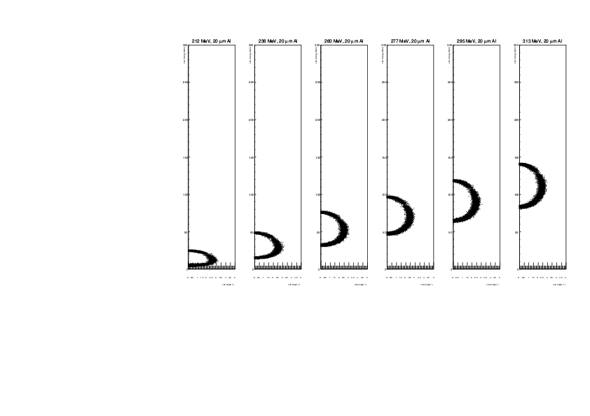
daid | heavy ion degrader foil - full / new | See entry https://elog.ph.ed.ac.uk/ISOLDE/28 for a full description, but editing the same elog is altering attachment numbers etc.
Here I've added 20 um foil as well as 5.3 MeV/u (~313 MeV) 59Cu beam.
The first set is 59Cu(p,alpha)56Ni showing 56Ni in the heavy ion detector, with different beam energies and Al degrader foil thicknesses.
The second set is for 59Cu(12C,12C)59Cu scattering. |
| Attachment 1: degrader06_full.pdf
|

|
| Attachment 2: degrader10_full.pdf
|

|
| Attachment 3: degrader15_full.pdf
|

|
| Attachment 4: degrader20_full.pdf
|
|
| Attachment 5: degrader06_12C_full.pdf
|

|
| Attachment 6: degrader10_12C_full.pdf
|

|
| Attachment 7: degrader15_12C_full.pdf
|

|
| Attachment 8: degrader20_12C_full.pdf
|

|
|
32
|
Thu Oct 19 10:55:54 2017 |
Claudia | Meeting 19.10. | CERN-Edinburgh Liaison
- FC at end of SEC: manual
- Network access: port free.
- N2 gas ?
- -date for connection of SEC to our chamber: week 30. October, 2nd November alignment.
- collimator in front of chamber ?? contact Jorge Alberto about beam tuning in general (maybe add contingency high energy point) ? cc Karl
look for 4 deliveries: 2 bags gain resistors, 1 box luvac, 1 box farnell
2) Parts to be prepared in Edinburgh
- Iris: no news should be done today
- spare feedthrough for cooling, to be done.
- Al degrader: we have 2x10, 2x15 um (hole in center and light checked). 6 um still to prepare, 20 um maybe. mounts to be delivered.
- Photo diodes x2 along with degrader foil: PCB & photodiodes here. extra holes for ladder. drawings there. making degrader foil holder. target ladder remade. Preamps, amps? ask Tom. Cocknell preamp tested. 20 mv/MeV (250 MeV max). maybe borrow some more amps from miniball.
- Faraday cup SHV to SMA converter: needs to be glued together
- Window port for front of chamber? Peter to manufacture
- Extra ribbon cables are needed? need to check with calibration. Also need long ribbon cables. will be done today/tomorrow
- Photographs and diagrams of experimental setup -- organized clearly for beam operators during tuning: add technical drawing on elog Peter will make it coherent. Safety Folder/Risk Assessment. Safety Datasheets (Ethanol).
- Alignment -- 2 end caps and one target ladder mount for optics reflector (8 mm diameter?) For survey people. Peter: two ends are done, drawings for S2 and target ladder mount points are at workshop
- Adjustable feet to be produced for radial alignment: Toby, almost done
- degrading of 12C - on elog.
3)Decisions / Analysis
- Alpha analysis: dE and HI detectors seem ok, We need spare cables for Detector to preamplifier.
- Sort Routine — Ruchi +Alex+Tom
- Target ladder config finalization: 2 photodiodes, collimator (what size, we have 3 mm and 10mm), Beam viewer, 3 CH2 and 2 Carbon.
- Calibration of Target ladder positions. Peter / Daid
- CH2 and C sample choice. So far CH2 Target 1: 30+25 (480ug/cm2); CH2 Target 2: 16 (400 ug/cm2). Check combination 33+1+10. New Ch2 from Paul - all will be sent here
4) CERN Presence:
- Ruchi: 22 Oct - ~20 Nov
- Mirco: 22-27 Oct, 5- ~20 Nov ?
- Claudia: 22-27 Oct, 5- ~20 Nov
- Daid: from 30 Oct
- Peter: from ~1 Nov
- Toby: from 30 Oct
- Alex 6-11 Nov
- Tom 8- ?? Nov
Sarah: 8 - ?? Nov
|
|
31
|
Thu Oct 12 12:45:54 2017 |
Claudia | Meeting 12.10.17 | Email sent to Karl and Olof about
- FC at end of SEC
- Gain resistor package
- Network access
- N2 gas
- date for connection of SEC to our chamber
- collimator in front of chamber ?
Next week call Karl. Daid will look at old Olof emails
2) Parts to be prepared in Edinburgh
- - Iris under construction, add. stop so it does not close all the way. coming along nicely. might have to increase detector distance a bit for safety. no news
- spare feedthrough for cooling, to be done
- Al degrader: We have 15 um and 6&10 um in Edinburgh, Daid will check if light-tight. We will prepare one 15, one 10 and on 6, possibly backups. Make hole, we have frames. more frames
- Photo diodes x2 along with degrader foil: PCB & photodiodes here. extra holes for ladder. coming along. 2 diodes need a bit less than 2 space, 10 spaces in total, maybe 11. drawings there. Preamps, amps? ask Tom
- Faraday cup SHV to SMA converter: Peter on order
- Window port for front of chamber? Peter to manufacture
- Extra ribbon cables are needed? need to check with calibration. Also need long ribbon cables. Peter will make 2 new ones. Peter has bits
- Photographs and diagrams of experimental setup -- organized clearly for beam operators during tuning: add technical drawing on elog Peter will make it coherent. Safety Folder/Risk Assessment. Safety Datasheets (Ethanol). send to Karl
- Alignment -- 2 end caps and one target ladder mount for optics reflector (8 mm diameter?) For survey people. Peter: two ends are done, drawings for S2 and target ladder mountain points not made yet.
- Adjustable feet to be produced for radial alignment: Peter / Toby
3)Decisions / Analysis
- Alpha analysis: dE and HI detectors seem ok, We need spare cables for Detector to preamplifier.
- Sort Routine — ask Tom
- Target ladder config finalization: 2 photodiodes, collimator (what size, we have 3 mm and 10mm), Beam viewer, We need to verify how many positions we have. 3 CH2 and 2 Carbon.
- Calibration of Target ladder positions. Peter / Daid
- CH2 and C sample choice. So far CH2 Target 1: 30+25 (480ug/cm2); CH2 Target 2: 16 (400 ug/cm2). Check combination 33+1+10. New Ch2 from Paul —> Check thickness asap!
|
|
30
|
Thu Oct 5 11:34:34 2017 |
Claudia | Meeting 5.10.17 | POINTS FOR DISCUSSION
- Email sent to Karl and Olof about
- FC at end of SEC
- Gain resistor package
- Network access
- N2 gas
To ask still:
- date for connection of SEC to our chamber
- collimator in front of chamber ?
No reply, remind next week, best by phone
2) Parts to be prepared in Edinburgh
- -Iris under construction, add. stop so it does not close all the way. coming along nicely. might have to increase detector distance a bit for safety.
- spare feedthrough for cooling, to be done
- Al degrader: We have 15 um and 8 um in Edinburgh, Daid will check if light-tight. We dont have 8, but we have 10 and 6 um which should both be possible. We will prepare one 15, one 8 and on 6, possibly backups. Check what it would do for straggling if there is no hole in the middle of the foil. use 20 mm cookie cutter for circle. earth foils? Tom: Make hole, we have frames.
- Photo diodes x2 along with degrader foil: PCB for photodiodes. extra holes for ladder. coming along. 2 diodes need a bit less than 2 space, 10 spaces in total, maybe 11.
- Faraday cup SHV to SMA converter: Peter to order
- Window port for front of chamber? Peter to draw
- Extra ribbon cables are needed? Need short cables detector to preamp. Also need long ribbon cables. Peter will make 2 new ones
- Photographs and diagrams of experimental setup -- organized clearly for beam operators during tuning: add technical drawing on elog Peter will make it coherent. Safety Folder/Risk Assessment. Safety Datasheets (Ethanol).
- Alignment -- 2 end caps and one target ladder mount for optics reflector (8 mm diameter?) For survey people. Peter: two ends are done, drawings for S2 and target ladder mountain points not made yet.
- Adjustable feet to be produced for radial alignment: Peter / Toby
3)Decisions / Analysis
- Alpha analysis: dE and HI detectors seem ok, We need spare cables for Detector to preamplifier.
- Sort Routine: Tom will provide sort routine and test file to look at real data.
- Target ladder config finalization: 2 photodiodes, collimator (what size, we have 3 mm and 10mm), Beam viewer, 3 CH2 and 2 Carbon.
- Calibration of Target ladder positions. Peter / Daid
- CH2 and C sample choice. So far CH2 Target 1: 30+25 (480ug/cm2); CH2 Target 2: 16 (400 ug/cm2)
|
|
29
|
Wed Oct 4 18:57:16 2017 |
dk | Digitized run notes from tests at CERN | Transcription of paper logbook for runs. Please check as I cannot read all the writing.
Wednesday 13/9/2017
Detectors installed:
2083-9, 74 um, dE layer
3080-23, 1012 um, E layer
2410-23, 65 um, HI layer
Det. Bias Leak
dE -24 0.46
E -350 2.61
HI -14 1.05
Runs 0 - 5 : junk
Run 10
Header: Alpha calibration
Date: 13/9/2017
Start: 18:03 (CERN)
Stop: 18:12
Note: Some cables disconnected to test CANNOT READ
Run 11
Header: Alpha calibration
Date: 13/9/2017
Start: 18:16
Stop:
Notes:
ADC Ch Notes
1 0-15 ok
1 16-31
2 0-15 7+8 only pulser
2 16-31 ok
3 0-15 only pulser
3 16-31 19 low gain (other notes but crossed out)
4 0-15 6 low (noise?), rest fine
4 16-31 only pulser
5 0-15 "probably okay"
5 16-31 "probably okay"
6 0-31 "probably okay"
-------
Thursday 14/9/2017
Det. Bias Leak
dE -24 0.44
E -351 2.4
HI -14 0.95
Run 12
Header:
Date: 14/9/2017
Start: 11:50
Stop: 12:08
Note: Bad. Pulser switched on through run
Run 13
Header: Pulser ON
Date: 14/9/2017
Start: 12:07
Stop:
Notes: good
ADC Notes
1 ch 0 ... bad resolution in pulser
2 ch 7,8 no alphas
3 ch 0 low gain, ch 0-15 almost only pulser but maybe shieled from alpha source & low noise
3 ch 24 low resolution
4 ch 6 no alphas, ch 7 low gain for alphas but not for pulser
4 ch 16-31 no alpha (maybe shielded & low noise)
5 okay
6 okay
TDC missing #1-32, #1-80,120,123
14:00 before turning off biases:
Det. Bias Leak
dE -24 0.4
E -351 2.15
HI -14.5 0.89
15:15 - Vent to remove dE layer
Extra SSD cable arrives
TDC mapping
Det. Side TDC ch
dE p+n 16-63
E n+n 64-79
HI p+n 80-127
Bias detectors
Det. Bias Leak
E -350 1.83
HI -14 0.8
Run 15
Header:
Date: 14/9/2017
Start: 18:22
Stop: 18:25
Notes: Bad. Pulser to 2 Hz
Run 16
Header: Alpha source in front of E detector
Date: 14/9/2017
Start: 18:31
Stop:
Notes: Bad. CANNOT READ
Run 17
Header:
Date: 14/9/2017
Start: 18:32
Stop:
Notes: Bad. ADC #4 ch 6, 7 bad.
Switch U7e8 (??) (n+n side p+n) from E detector
Problem moved -> CANNOT READ
-------
Friday 15/9/2017
10:00 bias detectors
Det. Bias Leak
E -351 2.13
HI -14.5 0.88
T: -4.9 C
P: 4.9 x 10^-6 mbar
Run 19
Header: alpha-calib of E layer 3080-23
Date: 15/9/2017
Start:
Stop:
Notes:
No TDC data ...?
ADC Ch Comments
1 0-31 Pulser (only) in all channels except ch2 which has a few counts across whole spectrum (hair)
Resolutions range from 2.0 -> 7.0
Pulser centroid ~ channel 2800 in all spectra (except ch 2 of course)
2 0-15 Pulser in all channels, ~channel 2000 (i.e. similar gains)
Resolution ~ 2.0 ch, except ch 8 sigma = 4.5 ch
2 16-31 Pulser in all channels at ~channel 3000
Resolution ~ 2.0 ch, excehpt ch 24 which is 6.7 ch & ch 16: 4.35 ch.
3 0-31 Pulser & alphas in all channels
(Not 19...see below)
Resolution is *poor* in ch0
All gains look similar
Alpha spectra in similar channel numbers as for other ADCs, but pulser at only 1/2 the channel number
(A drawing is given to compare ch0 to ch1-15.)
3 19 Gain seems very low
Pulser @ channel 430, alphas @ channel 200
So about 1/5 of gain of others in ADC 3 channels
4 0-15 All but ch 6 very similar (good)
ch 6: Pulser in similar channel to other spectra, but narrower (~4 ch, c.f. ~8-10 channels for other spectra.)
And alphas are much lower gain, appearing ~ ch 70, c.f. 1100 for others
4 16-31 All okay. Triple alpha @ ~ channel 1150, pulser @ 2800
5 0-31 All okay (though low gain - deliberately)
6 0-31 Ok, see above for ADC 5 notes.
Det. Bias Leak
E -351 2.08
HI -14.5 0.88
Restart MIDAS; VME crate
=> TDC signals return
12:02 Removed E layer #3080-23 (HI layer #2410-23 remains unchanged)
New 1035 um Si installed #2951-22. It uses a different bias voltage than the previous E layer (-160 vs. -351 V)
12:50 Stop DAQ (run 22 larger than necessary)
Run 23 (?? no note)
Header:
Date:
Start:
Stop:
Notes:
ADC ch Comments
1 0-15 Pulser only, similar gains
ch 2 no pulser (hair)
No alphas (unsurprising!)
1 16-31 Pulser only, similar gains
All okay.
(No alphas, unsurprising!)
2 0-31 Pulser only, no alphas, similar gains
All okay
3 0-15 Pulser + alphas
alphas in all strips
alpha similar gains and resolutions
pulser in ch 0 at ~1/2 amplitude
3 16-31 Pulser + alphas.
ch 19 pulser and alphas at much reduced channel number ~1/5 gain
4 0-15 Pulser + alphas
ch 6 no alphas - Pulser narrow (no detector capacitence?)
ch 7 alphas at reduced gain (~1/5), pulser narrow
4 16-31 All good
5 0-31 All good (low gains - by design)
6 0-31 All good (low gains - by design)
v767 #1 TDC
ch Comments
0 1 peak
1-15 No data
16-31 1 peak
32 No peaoks
33 1 peak + 1 small peak
34-44 2 peaks
45-47 1 peak
48 1 peak + hair
49-52 1 peak
53 1 peak + hair
54-56 2 peaks
57-63 1 peak
64-79 broad region of data (alphas?)
80-86 1 peak
87 1 peak + 1 smaller peak
88 Mainly 1 or 2 peaks + lots of hair
89 1 peak
90,91 2 peaks
92-95 1 peak
96 1 peak
97-127 Mainly 1 peak
Cable for 1 mm E detector must be faulty
Before opening the chamber:
Det. Bias Leak
E -160 1.12
HI -14.5 0.92
(When trying to switch the cable to the SSD, apparently it was not fully connected. Some time is lost to pump, vent, check, etc)
After new cabling is confirmed and evacuation is complete:
Det. Bias Leak
E -160 1.17
HI 14.5 0.96
Run 24
Header: Check new cable
Date: 15/9/2017
Start: 16:18 (UK)
Stop: 16:35 (UK)
Notes:
ADC ch Comments
3 0-15 okay
3 16-31 ch 19 low gain
4 0-15 ch 5, ch 7 low gain
4 16-31 okay |
|
28
|
Thu Sep 28 03:38:18 2017 |
dk | heavy ion degrader foil - updated | --original email text--
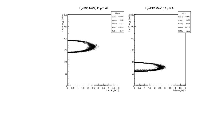
Using Claudia's code, I added a layer of Al foil before the heavy ion
silicon detector. The attached plots correspond to the heavy ion
portion of fig 3(a) in the proposal. Thus it only uses ground-state
transitions and doesn't account for geometry or efficiency etc. I opt
to show only the highest and lowest beam energies for each simulation.
As I said before, something between 10 and 20 um of Al was likely to
be the correct choice, which is confirmed. 10 um is almost to thin to
guarantee the signals are below 200 MeV, while for 20 um we start
having issues of detecting the lowest energy recoils for the low
energy run.
We can discuss the selection in more detail at the next meeting, but
most probably we can just use some kitchen foil, adopting whatever its
thickness of 13 to 15 um depending what we find.
The attached file starts with no degrader, then adds 10 um Al, and 1
um Al steps up to 20 um.
--Updated 2 Oct to include 5 um ~ 10 um--
As ~185 MeV is the maximum energy, but the gain resistors may vary by up to ~10%, then the 'maximium safe energy' is about 160 MeV. This we can get for the highest energy run
with 15 um Al (we have it in stock); however, then the lowest energy case becomes about 30 MeV, or less than 1 MeV/u, which may be an issue for straggling etc. So we will
prepare two foils, as it is seen even for the low energy beam, it comes almost to 190 MeV without a degrader foil. In fact, any foil thickness between 5 ~ 10 um may be okay
(we have 8 um in stock).
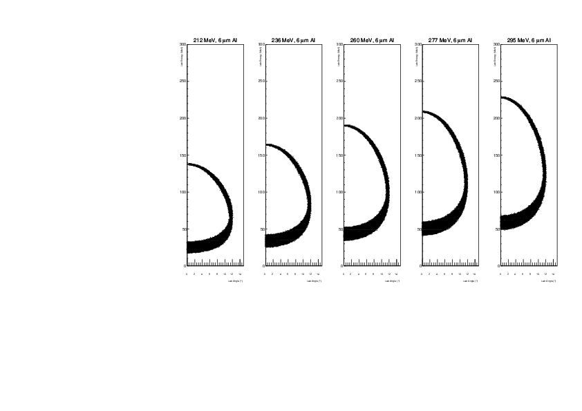
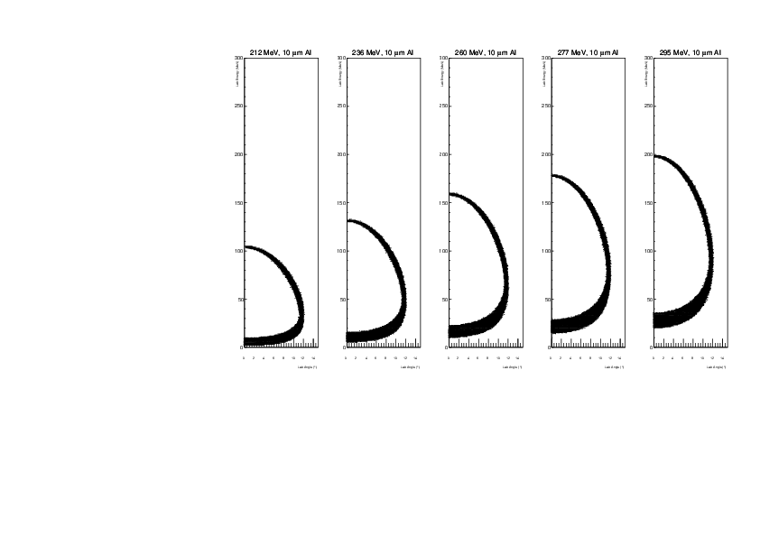
Using also all 5 energies (212, 236, 260, 277, 295) then we see that the two lowest energies are okay for 8 um foil, and the three highest energies are suitable for 15 um foil.
NB: 19 Oct I deleted 15 um (previously attachment 2) and now it is attachment 8.
Note that the beam energy order (right to left, left to right) differs between the first PDF and the second two.
--4 Oct--
Existing 8um Al foils are not the right size. Check 6 um and 10 um in detail, as we have more stock of these two. Attached.
--12 Oct--
Attachments 5-7 show the 59Cu energy after the degrader foils for elastic (12C,12C) scattering. Foil thicknesses are 6, 10, 15 um of Al, respectively. Note that the angular
range shows up to 15 degrees (larger than the case of the (p,a)). |
| Attachment 1: degrader.pdf
|


|
| Attachment 2: degrader08_full.pdf
|

|
| Attachment 3: degrader06_full.pdf
|

|
| Attachment 4: degrader10_full.pdf
|

|
| Attachment 5: degrader06_12C_full.pdf
|
|
| Attachment 6: degrader10_12C_full.pdf
|
|
| Attachment 7: degrader15_12C_full.pdf
|

|
| Attachment 8: degrader15_full.pdf
|

|
|
Draft
|
Thu Sep 28 03:34:20 2017 |
dk | heavy ion degrader foil |
--text from email--
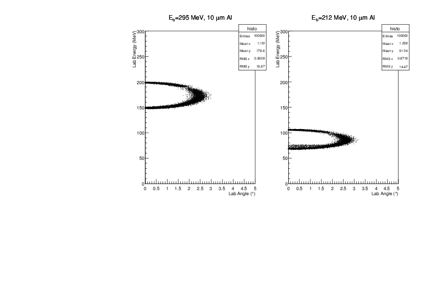
Using Claudia's code, I added a layer of Al foil before the heavy ion
silicon detector.  The attached plots correspond to the heavy ion
portion of fig 3(a) in the proposal.  Thus it only uses ground-state
transitions and doesn't account for geometry or efficiency etc.  I opt
to show only the highest and lowest beam energies for each simulation.

As I said before, something between 10 and 20 um of Al was likely to
be the correct choice, which is confirmed.  10 um is almost to thin to
guarantee the signals are below 200 MeV, while for 20 um we start
having issues of detecting the lowest energy recoils for the low
energy run.

We can discuss the selection in more detail at the next meeting, but
most probably we can just use some kitchen foil, adopting whatever its
thickness of 13 to 15 um depending what we find.

The attached file starts with no degrader, then adds 10 um Al, and 1
um Al steps up to 20 um. |
| Attachment 1: degrader.pdf
|



|
|
26
|
Mon Sep 25 14:50:46 2017 |
dk | To do list before main exp. - update from meeting 28th September | NB: This list may be incomplete!
CERN side:
Beam operators hope for a FC which can be automated at the end of SEC: Olof ?
Gain resistors (and other items) sent to CERN. Where are they? KJ has them? Check with Karl
w26 PC needs to get online. Contact Olof when we return to ISOLDE to confirm the network port is still free.
Daid. Need to register the device to CERN
Dry N2 bottle: ask Karl
Edinburgh side:
Iris automated controls and mounts: in construction. Add additional stop so doesnt close all the way. Peter
Cooling line chamber feed through: get spare. Peter
Get Al degrader foil for heavy ions (~13 um), mount on dummy frame etc. probably fine from store. Should get 15
um for highest beam energy. With lowest beam energy we might need to change the foil: Daid
Alpha spectral analysis: to be sorted. Daid, Claudia, Tom, Ruchi
Sort routines for dE-E plots, etc, for online analysis: Tom
Photo diodes x2 along with degrader foil: PCB for photodeiodes, PCB for photodiodes. extra holes for ladder. Peter
Target ladder config finalization: 2 photodiodes, collimator (what size, we have 3 mm and 10mm), Beam viewer,
We need to verify how many positions we have. Need at least 2 CH2 and 1 Carbon. Daid, Claudia
Extra ribbon cables are needed? need to check with calibration. Also need long ribbon cables
Beam viewer: see target ladder
Faraday cup SHV to SMA converter: Peter
Window port for front of chamber? Peter
Photographs and diagrams of experimental setup -- organized clearly for beam operators during tuning: add
technical drawing on elog.
Alignment -- 2 end caps and one target ladder mount for optics reflector (8 mm diameter?) For survey people. Peter
Adjustable feet to be produced for radial alignment: Peter / Toby
Contact CERN about date for beam connection: As soon as possible after 20th October. Talk to Karl/Olof.
Collimator at exit of SEC ? needs to be aligned. Ask what the other beamlines do - does olof have collimator
ahead of his chamber
Calibration of Target ladder positions. Peter / Daid
Email to Karl & Olof about:
- FC after SEC
- Parcel of gain resistors
- date for connection of SEC to our chamber
- collimator in front of chamber ?
- N2 bottle |
|
25
|
Thu Sep 21 14:54:00 2017 |
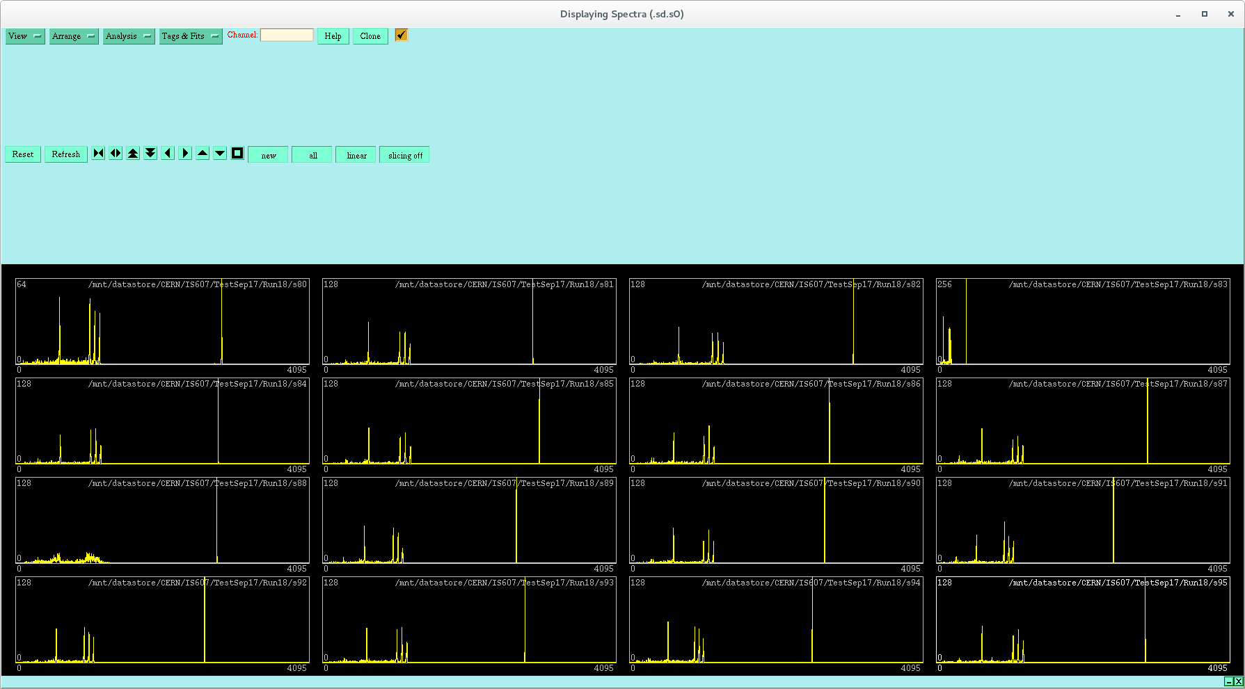
Claudia | Alpha Calibration Spectra | Alpha Calibration Runs (need to check settings in logbook)
0-63: dE detector and 32-47 is n+n; 64-127 E detector and 96-111 is n+n; 128-191 HI detector
Run 13: alpha source in fromt of dE detector (0-63). All detectors connected.
- 0-15 OK
- 16-31 OK
- 32-47 pulser appears at higher amplitude, alphas in a similar spot
- 48-63 OK
- 64-79 ch64 low gain but only for pulser (alphas look fine)
- 80-95 ch83 low gain, ch88 bad resolution. some strips show alphas
- 96-111 ch102 no alphas, ch103 low gain
- 112-127 pulser OK
- 128-191 (HI detector) looks ok
-
-
dE Layer is Removed
Run 15: alpha source in front of E detector, no dE
- 0-15 OFF
- 16-31 OFF
- 32-47 OFF
- 48-63 OFF
- 64-79 ch64 low gain but only for pulser (alphas look fine)
- 80-95 ch83 low gain, ch88 bad resolution.
- 96-111 ch102 no alphas, ch103 low gain
- 112-127 OK
Run 16: alpha source in front of E detector, no dE
- 0-15 OFF
- 16-31 OFF
- 32-47 OFF
- 48-63 OFF
- 64-79 ch64 low resolution, low gain but only for pulser
- 80-95 ch83 low gain, ch88 bad resolution.
- 96-111 ch102 /ch103 problem
- 112-127 OK
Run 18 does not seem to be in Run book
Run 18: alpha source in front of E detector,
- 0-15 OFF
- 16-31 OFF
- 32-47 OFF
- 48-63 OFF
- 64-79 ch64 as Run 16
- 80-95 ch83 as Run 16
- 96-111 alphas there but there are two pulser peaks in all segments, and a lot of alpha peaks...
- 112-127 OK
Run 19: same settings as Run 16
- 0-15 OFF
- 16-31 OFF
- 32-47 OFF
- 48-63 OFF
- 64-79 ch64 as Run 16
- 80-95 ch83 as Run 16
- 96-111 102/103 empty/low gain
- 128-143 OK
- 144-159 152-154 low resolution
- 160-175 OK
- 176-191 OK
For later runs the information is taken from logbook as no runs have been saved:
Run 23: E detector switched to #2951-22
- 0-15 OFF
- 16-31 OFF
- 32-47 OFF
- 48-63 OFF
- 64-79 ch64 as Run16
- 80-95 ch83 as Run 16
- 96-111 102/103 empty/low gain
- 112-127 OK
Run 24 Cable for 1 mm E detector must be faulty; Check new cable
- 64-79 OK
- 80-95 ch 83 low gain
- 96-111 ch 101, ch 103 low gain
- 112-127 OK
|
| Attachment 1: Screenshot_from_2017-09-21_14-43-48.png
|
|
| Attachment 2: Screenshot_from_2017-09-21_14-43-17.png
|

|
|
24
|
Tue Sep 19 14:54:47 2017 |
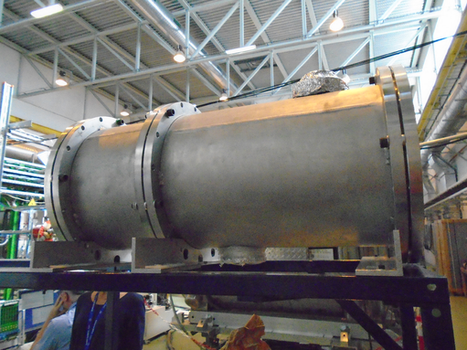
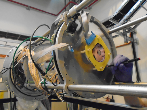
Claudia, Toby | Setup Photos | |
| Attachment 1: DSC01138.JPG
|
|
| Attachment 2: DSC01141.JPG
|

|
| Attachment 3: DSC01146.JPG
|

|
| Attachment 4: DSC01148.JPG
|

|
| Attachment 5: DSC01169.JPG
|

|
| Attachment 6: DSC01170.JPG
|

|
| Attachment 7: DSC01171.JPG
|
|
| Attachment 8: DSC01172.JPG
|

|
| Attachment 9: DSC01176.JPG
|

|
| Attachment 10: DSC01182.JPG
|

|
| Attachment 11: image1.JPG
|

|
| Attachment 12: image2.JPG
|

|
| Attachment 13: image3.JPG
|

|
| Attachment 14: image4.JPG
|

|
|